1
PowerPac™ Basic
Power Supply
Instruction
Manual
Catalog Number
164-5050
For Technical Service Call Your Local Bio-Rad Office or in the U.S. Call 1-800-4BIORAD (1-800-424-6723)
Table of Contents
Page
Safety...........................................................................................................
Section 1
Introduction ..............................................................................................1
1.1
1.2
Overview................................................................................................................1
Unpacking..............................................................................................................2
Section 2
Control Features.......................................................................................3
Section 3
Setup and Operation ................................................................................4
Section 4
Maintenance and Troubleshooting ..........................................................7
4.1
4.2
4.3
4.4
Maintenance...........................................................................................................7
Troubleshooting .....................................................................................................7
Replacing a Fuse ....................................................................................................9
Firmware Version Number.....................................................................................9
Appendix A Specifications ..........................................................................................10
Appendix B Warranty and Ordering Information....................................................11
List of Figures
1. Front View.
2. Rear View.
3. Front View with Legs in Lowered Position.
4. Front Panel.
5. Power Leads Connected Correctly.
6. Power Leads Connected Incorrectly.
7. Rear View Showing Fuse Drawer with Notches.
Copyright © (2002) Bio-Rad Laboratories, Inc. All rights reserved.
Safety
Caution/Warning
!
!
PowerPac power supplies use high output voltages that are electrically isolated from earth
ground to minimize the risk of electrical shock to the user. The following guidelines should
be observed and followed when using a PowerPac power supply.
!
PowerPac power supplies have passed test for operation at temperatures between 0º and 40º C,
with relative humidity between 0 and 95% non-condensing. Operating the power supply
outside these conditions is not recommended by Bio-Rad and will void the warranty.
1. To ensure adequate cooling of the power supply, be sure that there is at least 6 cm
clearance around the power supply. Do not block the fan vents at the rear of the unit.
2. Always connect the power supply to a 3-prong, grounded AC outlet, using the 3-prong
AC power cord provided with the power supply.
3. Bio-Rad electrophoresis cells have molded two-prong plugs that are inserted into the
power supply's high voltage output jacks. These plugs have been EN 61010* certified
for safety compliance for use with PowerPac power supplies. Use of other plugs or
banana jacks is done at the user's own risk and is not recommended by Bio-Rad. When
inserting and removing the molded two-prong plug, always grasp the plug by the molded
support at the rear of the plug. Do not grasp the individual prong ends.
4. Do not operate the power supply in extreme humidity (>95%) or where condensation
can short the internal electrical circuits of the power supply.
5. When taking the power supply into a cold room, the unit can be operated immediately.
However, when removing the power supply from the cold room, let the unit equilibrate
to room temperature for a minimum of 2 hours before using it.
6. Never connect a high voltage output lead to earth ground. This defeats the floating
electrical isolation of the power supply and exposes the user to potentially lethal high
voltages.
Important
This instrument is intended for laboratory use only.
This product conforms to the class A standards for Electromagnetic Emissions, intended
for laboratory equipment applications. It is possible that emissions from this product may
interfere with some sensitive appliances when placed nearby or on the same circuit as those
appliances. The user should be aware of this potential and take appropriate measures to
avoid interference.
Bio-Rad's PowerPac power supplies are designed and certified to meet EN 61010* safety
standards. Certified products are safe to use when operated in accordance with the instruction
manual. This safety certification does not extend to electrophoresis cells or accessories that
are not EN 61010 certified, even when connected to this power supply.
This instrument should not be modified or altered in any way. Alteration of this instrument
will void the manufacturer's warranty, void the EN 61010 certification, and create a potential
safety hazard for the user.
Bio-Rad is not responsible for any injury or damage caused by the use of this instrument
for purposes other than those for which it is intended, or by modifications of the instrument
not performed by Bio-Rad or an authorized agent.
*EN 61010 is an internationally accepted electrical safety standard for laboratory instruments.
B
Section 1
Introduction
1.1 Overview
The PowerPac Basic provides constant voltage or constant current to instruments used
in electrophoresis. The power supply operates at the values specified for the constant
parameter. However, to prevent damage to the electrophoresis cell, the PowerPac Basic
provides automatic crossover to constant current or constant voltage, depending on which
set value is first reached. When the set limit of the non-constant parameter is reached, and
the power capability of the unit is not exceeded, the power supply will switch, making the
non-constant parameter the new constant parameter.
Output specifications:
Voltage:
Adjustable from 10 to 300 Volts, in 1 volt increments.
Current:
Adjustable from 4 to 400 milliamperes (mA) in 1 mA increments.
Power:
75 watts (maximum).
Four output jacks:
Up to four identical electrophoresis cells can be connected in parallel
to the power supply.
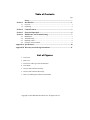
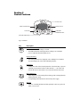
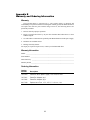
{
FRONT PANEL
OUTPUT JACKS
Fig. 1. Front View.
AC INLET
POWER SWITCH
FUSE
Fig. 2. Rear View.
1
The PowerPac Basic has the following features:
•
•
•
•
•
•
•
Programmable constant voltage or constant current with automatic crossover
Timer control from 0 to 999 minutes
3-digit LED display
Pause mode for editing running parameters
Automatic detection of no load conditions and rapid changes in resistance
Power Failure Detection in timed modes allowing completion of run
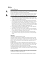
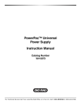
Stackable case with adjustable viewing angle via flip down legs (see Figure 3)
LEGS
(LOWERED POSITION)
Fig. 3. Front View with Legs in Lowered Position.
1.2 Unpacking
When you receive the power supply, carefully inspect the container for any damage which
may have occurred in shipping. Severe damage to the container may indicate damage to the
power supply itself. If you suspect damage to the unit, immediately file a claim with the carrier in accordance with their instructions before contacting Bio-Rad Laboratories.
After unpacking the PowerPac Basic, remove the plastic film from the translucent green
top case. The plastic film may leave a residue. If so, clean with a soft, damp cloth.
Contents include:
• PowerPac Basic power supply
• Power cord
• Instruction manual
• Warranty card
• Declaration of conformity
If any part is missing or damaged, contact Bio-Rad Laboratories immediately.
2
Section 2
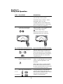
Control Features
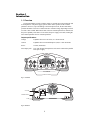
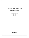
3 DIGIT LED
DISPLAY MODE KEY
SCROLL KEYS
STOP KEY
CONSTANT
PARAMETER KEY
RUN AND PAUSE KEY
Fig. 3. Front Panel.
Key
Description
Constant Parameter Key:
• Selects either constant voltage or current.
• The LED indicates the selected parameter. During a run, maximum
power is indicated when both LED’s are lit.
Display Mode Key:
• Selects the parameter to be displayed (volts, milliamperes or minutes).
The LED displays the value of the indicated parameter.
Scroll Keys:
• Changes the value of the selected parameter. If the Scroll Key is pressed
constantly for more than 5 units in either direction, +/-, the values will
increase/decrease in increments of 10 to reach the desired value faster.
Run & Pause Key:
• Starts and pauses a run. Pausing allows editing of the constant parameter
and the parameter values.
• Corresponding LED indicates the status of the power supply.
Stop key:
• Stops run. Constant parameter and limit parameter values are preserved.
Timer is reset to zero.
3
Section 3
Setup and Operation
STEP
PROCEDURE
DESCRIPTION
1.
Turn power on.
Press the power switch located on the right
side of the unit to the on position.
The default setting is constant V, and the
LED display shows zero value.
To display firmware version number, hold
down constant parameter key while turning
the power switch to the on position.
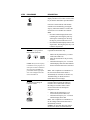
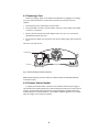
2.
Connect the electrophoresis
cell(s) to the power supply.
The power leads are color coordinated to the
output terminals in red and black.
indicates high voltages.
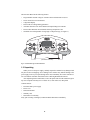
Note: Power leads must be inserted
perpendicular to the curve of the case.
Fig. 5. Power leads connected correctly.
Fig. 6. Power leads connected incorrectly.
3.
Press the Constant key to select the constant
parameter, either voltage or current. The
LED on the parameter key corresponding to
the selected constant parameter will light up.
The display shows the zero value for the
constant parameter.
Select the constant parameter
or
4.
Enter a value for the constant
parameter using the scroll key.
Use the scroll key to enter the desired value.
Voltage: 10–300V adjustable in 1V increments.
Current: 4–400 mA adjustable in 1 mA
increments.
Note: If the scroll key is pressed constantly
for more than 5 units in either direction, +/-,
the values will increase/decrease in increments
of 10 to reach the desired value faster.
5.
Enter value for limit parameter.
For volts
For milliamperes
4
Use the parameter key to select the limit
parameter. The maximum default value,
300V or 400mA, is displayed. Select a suitable
limit value to avoid excessive power
conditions for the application.
STEP
PROCEDURE
DESCRIPTION
6.
Programming a timed run
Use the parameter key to select time. The
display will show a zero value. Use the scroll
key to enter the desired time up to 999 minutes.
If no time is entered the run will continue
until the run is terminated by pressing the
stop key. When 999 minutes is reached, the
clock resets to zero and the run continues.
Note:
• In a timed run the displayed time is the
remaining time. Pressing the pause key
will keep the remaining time. Pressing
the stop key will reset the time to zero.
•
7.
Optional; available only when
a timed run is programmed.
Power Failure detection.
In an untimed run the displayed time is the
elapsed time. Pressing the pause key will
retain the elapsed time.
Activating the Power failure detection mode
is possible for timed runs only.
•
•
•
Caution: Always use the stop key
to terminate a run in progress. Use
of the power switch to terminate a
run in progress is treated as a
power failure and the appropriate
error code is displayed when the
unit is turned back on
8.
Optional
De-activation of change in
resistance feature.
Make sure the parameter key is in time
mode (time LED is lit)
Enter the desired time if not previously
entered
Hold down the stop key for ~2 seconds
until the display shows Pfd. This indicates
the Power Failure Detection is activated.
Note: After completion or termination of a
run, the Power Failure Detect mode is
automatically de-activated. See Section 4.2,
Troubleshooting, for details on Power
Failure Detect error messages.
Certain applications exhibit fluctuations in
resistance that can trigger the change in
resistance error codes. If this is the case,
the change in resistance feature can be
de-activated to allow un-interrupted
completion of a run.
•
Make sure the parameter key is in
current mode (current LED is lit)
• Hold down the stop key for ~2 seconds
until the display shows dE9
Note: After completion or termination of a
run the Change in Resistance Detection is
automatically activated.
Caution: De-activating this safety feature
increases the chance of electrical hazard.
STEP
PROCEDURE
DESCRIPTION
9.
Start the run
Press the run/pause key to start the run.
The run LED is lit.
10.
Viewing and editing options
during a run.
•
•
Viewing: Press the parameter key to
view the corresponding value on the
display
Editing: Edit the constant parameter
value and the time value for timed runs
Note:
Editing the limit value is possible in the
pause mode. To change from an un-timed to
a timed run, stop the run and re-program.
11.
Pause mode
Press run/pause key during a run to enter
the pause mode.
When the pause LED is lit it is possible to:
• Safely make adjustments to the
instrument connected to the power
supply
• Edit the values for all parameters
•
Change the constant parameter
Note:
To change from an un-timed to a timed run,
stop the run and re-program.
12.
End of run.
When a run is completed, i.e., a timed run
has ended or an untimed run is stopped, the
constant parameter value and limit parameter
value are preserved. The timer is reset to zero.
Neither the run nor the pause LED is lit,
indicating that no power is supplied to the
output jacks.
13.
Terminating a timed run in
progress
Press the stop key to terminate a timed run.
The constant parameter value and limit
parameter value are preserved. The timer is
reset to zero. Neither the run nor the pause
LED is lit indicating that no power is
supplied to the output jacks.
14.
Powering down
Press the stop key before turning the power
switch to the off position. If this is not done,
a power failure will be detected causing an
automatic restart if the Power Failure
Detection is enabled.
6
Section 4
Maintenance and Troubleshooting
4.1 Maintenance
The PowerPac Basic requires little maintenance to assure reliable operation. To clean
the case, first unplug the power supply. Use a damp cloth to wipe down the outer case.
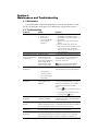
4.2 Troubleshooting
Problem
Cause
Solution
No display/lights/fan
1. No AC power.
2. Blown fuse.
3. Power switch
exercised rapidly to
the on and off
positions.
Repeated blown fuses
Leads from cell are
not long enough to fit
output jacks
Hardware failure
Output terminals for the
PowerPac Basic are
recessed 16 mm to
meet safety regulations.
Some leads are not
long enough to make
electrical connection.
No load detected
1. Check if PowerPac Basic is
unplugged, or problem with AC
power source, or power switch is in
off position.
2. Replace fuse. See section 4.3 for
details.
3. The unit needs to be reset. Turn
power switch to the off position, wait
5–10 seconds, then turn power
switch to the on position to resume
normal operation.
Contact Bio-Rad Technical Resources.
Use the PowerPac Adaptor, which
accommodates most standard 4 mm
banana plugs, to make a secure
electrical connection.
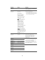
E1 error code
displayed
•
Note: Use of the PowerPac Adaptor
voids EN61010 safety provisions.
Verify all electrical connections.
Verify buffer levels where appropriate.
Instrument not
connected to PS
•
E2 error code
displayed
The current load is
below 4mA
Over current (load
current greater then
400 mA)
Check for and correct any short circuit
or excessive load problem. Excessive
load due to high buffer concentration
will require the buffer be remade.
Then,
• Press
key to resume the run or,
• To clear the error code, press any
key (other then
key).
E3 error code
displayed
E5 error code
played
E6 error code
displayed
E7 error code
displayed
Over voltage (load
voltage over 300 V)
Turn power supply off, then on to reset.
If problems persists, contact Bio-Rad
Technical Resources.
A power failure occurred during a timed run with Power Fail Detection
(PFd) activated, and run is completed. Power Fail detection (Pfd) is
de-activated after completion or termination of each run.
A power failure occurred during a timed run without Power Fail
Detection (PFd) activated, and run is not completed.
Power Failure occurred during an untimed run or the power switch
was turned off before pressing stop,. and run is not completed.
Power Fail detect (Pfd) cannot be activated for untimed runs.
Problem
Cause
Solution
E8 error code
displayed
Regulation error
Turn power supply off, then on to reset.
If problem persists, contact Bio-Rad
Technical Resources
E9 error code
displayed
Change in Load
Resistance.
Check and correct any potential
resistance problem then,
• press run/pause key to resume run or,
• press any key, other than the run/pause
key, to clear the error code.
The PowerPac
Basic detects drastic
changes in resistance
which may indicate
failure of the cell’s power
leads or a loose output
connection.
Note: Certain applications
exhibit fluctuations in
resistance that can
trigger the change in
resistance error code.
If this is the case, the
change in resistance
feature can be deactivated
to allow uninterrupted
completion of a run.
(see Section 3, Step 8)
E10 error code
displayed
E12 error code
displayed
E13 error code
displayed
E14 error code
displayed
E15 error code
displayed
E16 error code
displayed
E17 error code
displayed
E98 error code
displayed
E99 error code
displayed
Caution: Deactivating this
safety feature increases the
possibility that a failure of the
power leads or loose output
connection will not be
detected.
Unacceptable value(s)
Clear the code by pressing any key
entered
other than the run/pause key.
Then, enter values within range of
PowerPac Basic and press the
run/pause key
Internal Over Current
Possible power supply malfunction.
Internal Short Circuit
Internal Short Circuit
Check for and correct problems such
as dirty contacts, frayed wires,
excessive buffer concentration. Then
press any key other than the run/pause
key to clear the code.
Hardware failure
Contact Bio-Rad Technical Resources
Internal Over Voltage
Hardware failure
Internal system error
Internal system error
8
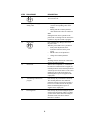
4.3 Replacing a Fuse
If there is no display, lights, or fan, and the PowerPac Basic is plugged into a working
AC power outlet with the power switch in the on position, the fuse may need to be
replaced.
1. Disconnect the power cord from the electrical outlet.
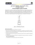
2. Insert a flat blade screwdriver into the notches of the power entry module's fuse holder
to release it. See Figure 5.
3. Remove the fuse from the fuse holder. Replace with 2.5A, 250V, 5 X 20 mm fuses
(Bio-Rad part number 900-7283).
4. Re-insert the fuse holder into its position. Press the fuse holder gently until it snaps into
place.
The unit is now ready for use.
FUSE DRAWER
NOTCHES
Fig. 5. Rear View Showing Fuse Drawer with Notches.
Note: Repeated blowing of the fuse indicates a hardware failure and Bio-Rad should be
contacted for repair.
4.4 Firmware Version Number
To display the PowerPac Basic’s firmware version number while the power supply is
off, hold down the constant parameter key and concurrently turn the power switch to the on
position. All of the LEDs and segments in the 3 digit LED display will light. Release the
constant parameter key and the firmware version number will then appear for a few seconds.
The power supply is now ready for operation.
9
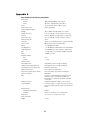
Appendix A
Specifications and Ordering Information
Input Power
nominal
actual
Fuses
Input Power Cord
Output (Programmable)
Voltage
Voltage Accuracy
Current
Current Accuracy
Power (maximum)
Terminals
Timer Control
Ripple
Line Regulation
Load Regulation
Drift
Noise
Readout Stability
Volts
Current
Safety Features
No load detection
Sudden load change detection
Overload/short circuit protection
Input line protection
Auto power up after power failure
Safety Compliance
EMI
Display Functions
Function Modes
Environmental
Operating Temperature
Humidity
Dimensions
Unit is stackable
Weight
100–120/220–240 VAC, 50 or 60 Hz
90–132 or 198–264 VAC, 50 or 60 Hz
2.5 A, 250 VAC, 5mm x 20mm, Type T
3-wire; grounded
10 V to 300 V, fully adjustable in 1 V steps
± 2% of reading or 3 volts, whichever is more
4 mA to 400 mA, fully adjustable in 1 mA steps
± 2% of reading or 3 mA, whichever is more
75 W
4-pair recessed banana jacks, floating in parallel
001 to 999 minutes, fully adjustable
< 1% @ 300 V and 70 W
< 1% @ 300 V and 70 W, 90–132 or 198–264VAC
<1% @ 300 V for a 50% change in output load
< 1% @ after 15 min warmup at 300 V and 70 W
55 dBA at 1 meter
±1 V
± 1 mA
Indicated by error message on display
Indicated by error message on display
Automatic power limit
Fuse on both hot and neutral
User-selectable, setup values maintained
EN-61010
Conforms to CE standards for Emissions and
Immunity class A, tested only at 230V. See
Declaration of Conformity for details. TUV EMC
certification
3-digit LED displays voltage, current, or time
Constant voltage, constant current, timer, pause
User-selectable automatic power-up after power
failure
0–40°C
0–95%, in the absence of condensation
25 cm (L) x 21 cm (W) x 8.5 cm (H)
1.1 kg
10
Appendix B
Warranty and Ordering Information
Warranty
The PowerPac Basic is warranted for 3 years against defects in materials and
workmanship. If any defects should occur during this warranty period, Bio-Rad Laboratories
will replace the defective parts without charge. However, the following defects are
specifically excluded:
1. Defects caused by improper operation.
2. Repair or modification done by anyone other than Bio-Rad Laboratories or their
authorized agent.
3. Use with cables or connectors not specified by Bio-Rad Laboratories for this power supply.
4. Deliberate or accidental misuse.
5. Damage caused by disaster.
For inquiry or request for repair service, contact your local Bio-Rad office.
Warranty Information
Model: _________________________________________________________________
Serial Number: ___________________________________________________________
Date of Delivery: _________________________________________________________
Warranty Period:__________________________________________________________
Ordering Information
Catalog
Number
Description
164-5050
PowerPac Basic power supply, 100–120/220–240V
165-5061
PowerPac Adaptor, qty 1
165-5066
PowerPac Adaptor, qty 2
900-7283
Replacement Fuse, 2.5 A, 250 V, 5 x 20 mm, 1 ea
11
Bio-Rad
Laboratories, Inc.
Web site www.bio-rad.com USA (800) 4BIORAD Australia 02 9914 2800 Austria (01)-877 89 01 Belgium 09-385 55 11 Brazil 55 21 2527 3454
Canada (905) 712-2771 China (86 21) 6426 0808 Czech Republic + 420 2 41 43 05 32 Denmark 44 52 10 00 Finland 09 804 22 00
France 01 47 95 69 65 Germany 089 318 84-0 Greece 30 210 777 4396 Hong Kong (852) 2789 3300 Hungary 36 1 455 8800
India (91-124)-2398112/3/4, 5018111, 6450092/93 Israel 03 951 4127 Italy 39 02 216091 Japan 03-5811-6270 Korea 82-2-3473-4460
Latin America 305-894-5950 Mexico 55-52-00-05-20 The Netherlands 0318-540666 New Zealand 64 9 415 2280 Norway 23 38 41 30
Poland + 48 22 331 99 99 Portugal 351-21-472-7700 Russia 7 095 721 1404 Singapore 65-64153188 South Africa 00 27 11 4428508
Spain 34 91 590 52 00 Sweden 08 555 12700 Switzerland 061 717 95 55 Taiwan (886 2) 2578 7189/2578 7241 United Kingdom 020 8328 2000
Life Science
Group
Bulletin 0000
US/EG
Rev A
00-000
0000
Sig 1204
4006213 Rev E