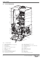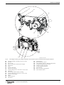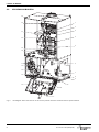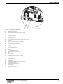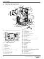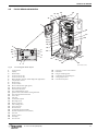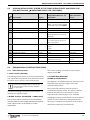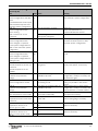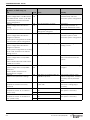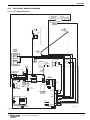
1
ENGINEER‘S SERVICE BOOKLET
FLOOR MOUNTED & WALL HUNG RSF GAS FIRED CONDENSING BOILERS
GREENSTAR CDi RANGE
FOR CENTRAL HEATING SYSTEMS AND INDIRECT FED DOMESTIC HOT WATER
This Service booklet covers the following
boiler ranges:
CDi Combi N.G.
8716115748-00.1Wo
CDi Combi L.P.G.
CDi System N.G.
CDi System L.P.G.
CDi Regular N.G.
CDi Regular L.P.G.
Highflow CDi N.G.
Highflow CDi L.P.G.
FS CDi Regular N.G.
FS CDi Regular L.P.G.
8 716 115 748 (2009/09)
UK/IE
TABLE OF CONTENTS
TABLE OF CONTENTS
1
Explanation of symbols and safety precautions 3
1.1
Explanation of symbols . . . . . . . . . . . . . . . 3
1.2
Safety precautions . . . . . . . . . . . . . . . . . . 3
8
Troubleshooting - FW 100 . . . . . . . . . . . . . . . . . 58
8.1
Troubleshooting using the display . . . . . . 58
8.2
Troubleshooting without the display . . . . 62
2
layout of boiler . . . . . . . . . . . . . . . . . . . . . . . . . . 4
2.1
CDi Combi boilers . . . . . . . . . . . . . . . . . . . 4
2.2
CDi System boilers . . . . . . . . . . . . . . . . . . 6
2.3
CDi regular boilers . . . . . . . . . . . . . . . . . . 8
2.4
Highflow CDi Combi boiler . . . . . . . . . . . 10
2.5
FS CDi Regular boilers . . . . . . . . . . . . . . 11
9
Troubleshooting - FR110 . . . . . . . . . . . . . . . . . . 63
9.1
Troubleshooting using the display . . . . . . 63
9.2
Troubleshooting without the display . . . . 67
OPERATION - CDi . . . . . . . . . . . . . . . . . . . . . . . 12
3.1
Initialisation . . . . . . . . . . . . . . . . . . . . . . . 12
3.2
Display messages . . . . . . . . . . . . . . . . . . 12
3.3
Operating elements CDi (Wall hung) . . . 13
3.4
First service level . . . . . . . . . . . . . . . . . . 13
3.5
Second service level . . . . . . . . . . . . . . . . 13
3.6
Resetting service functions to factory
settings . . . . . . . . . . . . . . . . . . . . . . . . . . 14
3.7
Select max. or min. heat output . . . . . . . 14
3.8
Reset the appliance . . . . . . . . . . . . . . . . . 14
11 Troubleshooting - TD 200 . . . . . . . . . . . . . . . . . 69
3
4
OPERATION - HIGHFLOW CDi and FS CDi
REGULAR . . . . . . . . . . . . . . . . . . . . . . . . . . . . . . 15
4.1
Initialisation . . . . . . . . . . . . . . . . . . . . . . . 15
4.2
Display messages . . . . . . . . . . . . . . . . . . 15
4.3
Operating elements . . . . . . . . . . . . . . . . . 16
4.4
First service level . . . . . . . . . . . . . . . . . . 16
4.5
Second service level . . . . . . . . . . . . . . . . 16
4.6
Resetting service functions to factory
settings . . . . . . . . . . . . . . . . . . . . . . . . . . 17
4.7
Select max. or min. heat output . . . . . . . 17
4.8
Reset the appliance . . . . . . . . . . . . . . . . . 17
5
Boiler service functions - CDi Combi & System
boiler . . . . . . . . . . . . . . . . . . . . . . . . . . . . . . . . . 18
5.1
First service level . . . . . . . . . . . . . . . . . . . 18
5.2
Second service level. . . . . . . . . . . . . . . . . 19
5.3
Explanation of service functions . . . . . . . 19
6
Boiler service functions CDi, Highflow CDi
& FS CDi Regular . . . . . . . . . . . . . . . . . . . . . . . . 23
6.1
First service level . . . . . . . . . . . . . . . . . . . 23
6.2
Second service level. . . . . . . . . . . . . . . . . 24
6.3
Explanation of service functions . . . . . . . 25
7
Rectifying faults . . . . . . . . . . . . . . . . . . . . . . . .
7.1
Indication of faults . . . . . . . . . . . . . . . . .
7.2
Summary . . . . . . . . . . . . . . . . . . . . . . . . .
7.3
Notes on using the fault code tables . . . .
7.4
Error codes on the display . . . . . . . . . . .
7.5
Faults that are not displayed . . . . . . . . .
2
10 Troubleshooting - RT10 . . . . . . . . . . . . . . . . . . . 68
12 Appendix . . . . . . . . . . . . . . . . . . . . . . . . . . . . . . 71
12.1 NTC sensor values, CDi appliances . . . . . 71
12.2 CDi fan speeds . . . . . . . . . . . . . . . . . . . . 71
12.3 Highflow CDi &
FS CDi Regular fan speeds . . . . . . . . . . . .71
12.4 NTC sensor characteristics Highflow CDi & FS
CDi Regular appliances . . . . . . . . . . . . . . .72
12.5 Electrical wiring diagrams . . . . . . . . . . . . 73
12.6 Code plugs used with CDi appliances . . . 78
12.7 Code plugs used with Highflow CDi & FS CDi
Regular appliances . . . . . . . . . . . . . . . . . .78
12.8 Approved corrosion inhibitors and anti-freeze
for central heating water . . . . . . . . . . . . .79
12.9 Possible sources of corrosive CFCs . . . . . 79
27
27
27
28
29
52
8 716 115 748 (2009/09)
EXPLANATION OF SYMBOLS AND SAFETY PRECAUTIONS
1
EXPLANATION OF SYMBOLS AND SAFETY PRECAUTIONS
1.1
EXPLANATION OF SYMBOLS
WARNING SYMBOLS
1.2
SAFETY PRECAUTIONS
IF YOU SMELL GAS
Safety instructions in this document are
framed and identified by a warning triangle
which is printed on a grey background.
B Do not smoke or strike matches
B Do not turn electrical switches on or off
B Put out naked flames
B Open doors and windows
Electrical hazards are identified by a
lightning symbol surrounded by a warning
triangle.
Signal words indicate the seriousness of the hazard in
terms of the consequences of not following the safety
instructions.
• NOTICE indicates possible damage to property or
equipment, but where there is no risk of personal
injury.
• CAUTION indicates possible personal injury.
• WARNING indicates possible severe personal injury.
B Keep people away from the affected area
B Turn off the control valve at the meter
B Call your gas company
or
B Call 0800 111 999
BOILER OPERATION:
This appliance must only be operated by a responsible
adult who has been instructed in, understands and is
aware of the appliance‘s operating conditions and
effects.
• DANGER indicates possible risk to life.
HEALTH AND SAFETY
IMPORTANT INFORMATION
The appliance contains no substances that contravene
the COSHH Regulations (Control of Substances
Hazardous to Health regulations 1988).
Notes contain important information in
cases where there is no risk of personal
injury or material losses and are identified
by the symbol shown on the left. They are
bordered by horizontal lines above and
below the text.
ADDITIONAL SYMBOLS
COMBUSTIBLE AND CORROSIVE MATERIALS
Do not store or use any combustible materials (paper,
thinners, paint etc.) inside or close to the appliance.
Chemically aggressive substances, such as halogenated
hydrocarbons.
The presence of halogenated hydrocarbons in the
combustion air causes surface corrosion on affected
metals.
Symbol
Meaning
B
a step in an action sequence
Æ
a reference to a related part in the document or to other related documents
•
a list entry
In order to limit the damage, the source of the air
contamination must be located and sealed off. If this is
not possible, the combustion air must be drawn from an
alternative clean source.
a list entry (second level)
FITTING AND MODIFICATION
–
Fitting the appliance and any controls to the appliance
must only be carried out by a competent engineer in
accordance with the current Gas Safety (installation and
use) Regulations.
Tab. 1
SERVICING
Advise the user to have the system serviced annually by
a competent, qualified engineer, such as British gas or
Gas safe registered personnel, using approved spares.
This will help to maintain the economy, safety and
reliability of the appliance.
8 716 115 748 (2009/09)
3
LAYOUT OF BOILER
2
LAYOUT OF BOILER
2.1
CDi COMBI BOILERS
20
67
9
611
O
09.1
27-
29
1
28
2
3
27
4
26
5
25
24
6
23
7
22
21
8
20
9
19
10
18
11
17
12
16
13
14
15
Fig. 1
1
2
3
4
5
6
7
8
9
10
11
12
13
14
15
4
CDi combi layout
Flame viewing window
Ignition electrode and flame sense electrode
Heat exchanger
Overheat thermostat
Access point for cleaning heat exchanger
Plate to plate DHW heat exchanger
Pump
System pressure gauge
Drain point
Mains cold water in
CH return
Charging link assembly
Gas inlet connection 22 mm compression
Cover for external wiring connections
Control panel in service position
16
17
18
19
20
21
22
23
24
25
26
27
28
29
Access cover for transformer & PCB
DHW out
CH flow
Trap / syphon outlet connection (22 mm plastic pipe)
Inlet pressure test point
Trap / syphon
Gas valve
DHW temperature sensor
Air / gas adjustment screw
Testing point for fan pressure
Fan
Primary sensor
Expansion vessel
Removable top case panel for servicing
8 716 115 748 (2009/09)
LAYOUT OF BOILER
48
40
6
39
37
38
36
32
48
41
47
46
43
42
44
55
54
53
52
61
9
45
60
59
58
57
56
8 716 115 748 - 01.1Wo
49
Fig. 2
6
9
32
36
37
38
39
40
41
42
43
44
45
46
47
50
51
This diagram shows the compact hydraulics and controls with the mantel and fascia panel removed
Plate to plate DHW heat exchanger
Drain point
Pump, modulating
Flow turbine
Unused port
Return connection to boiler heat exchanger
Auto air vent
Flow connection from boiler heat exchanger
DHW sensor
CH flow connection to isolation valve
DHW out connection
Cold water in connection
CH return connection to isolation valve
Diverter valve housing
Pressure relief valve
8 716 115 748 (2009/09)
48
49
50
51
52
53
54
55
56
57
58
59
60
61
Compact hydraulic mounting screw (2) to boiler
CH temperature control
Mains on/off indicator/diagnostic light (blue)
DHW temperature control
Central heating boost button
Service button
Burner on indicator light (green)
Master switch on/off
Holiday button
ECO button
Fault reset button
Display
System pressure gauge
Position for optional programmer
5
LAYOUT OF BOILER
2.2
CDi SYSTEM BOILERS
O
02.1
58-
4
12
06
2
67
24
1
23
2
3
22
4
21
5
20
19
6
18
17
7
16
8
15
14
9
13
10
11
12
Fig. 3
1
2
3
4
5
6
7
8
9
10
11
12
6
CDi System layout
Flame viewing window
Ignition electrode and flame sensing electrode
Heat exchanger
Overheat thermostat
Access point for cleaning heat exchanger
Pump
System pressure gauge
Drain point
Central Heating return
Gas inlet connection (22mm compression)
Cover for external wiring connections
Control panel in service position
13
14
15
16
17
18
19
20
21
22
23
24
Access cover for transformer and PCB
Central Heating flow
Trap /Syphon outlet connector (22mm plastic pipe)
Inlet pressure test point
Trap / Syphon
Gas valve
Air / Gas adjustment screw
Test point for fan pressure
Fan
Primary sensor
Expansion vessel
Removable top panel for servicing
8 716 115 748 (2009/09)
LAYOUT OF BOILER
25
26
27
29
28
30
25
31
32
35
36
49
48
47
46
45
37
38
39
40
41
44
Fig. 4
25
26
27
28
29
30
31
32
33
34
35
36
37
38
39
40
33
34
43
42
8716115 748-04.1Wo
This diagram shows the compact hydraulics and controls with the mantel and fascia panel removed
Compact hydraulic mounting screw (2) to boiler
Flow unit
Auto air vent
Return connection to boiler heat exchanger
Unused port
Pump
Pressure relief valve
Diverter valve housing
Central Heating return connection to service valve
Drain point
Internal bypass within plastic moulding
Central Heating flow connection to service valve
System pressure gauge
Display
Fault reset button
ECO button
8 716 115 748 (2009/09)
41
42
43
44
45
46
47
48
49
Holiday button
DHW temperature control
Power ON/OFF indicator / diagnostic light (blue)
Central Heating temperature control
Position for option controller
Central heating boost button
Service button
Burner on indicator light (green)
Power ON/OFF switch
7
LAYOUT OF BOILER
2.3
CDi REGULAR BOILERS
23
1
22
2
3
21
4
20
5
19
18
17
6
16
15
7
14
8
9
13
10
11
12
8716115748-05.1Wo
Fig. 5
8
The diagram shows the controls in the service position with the mantle and fascia panel removed
8 716 115 748 (2009/09)
LAYOUT OF BOILER
33
32
31
30
;
?
24
25
26
27
29
Fig. 6
1
2
3
4
5
6
7
8
9
10
11
12
13
14
15
16
17
18
19
20
21
22
23
24
25
26
27
28
29
30
31
32
33
28
8716115748-02.1Wo
Front of the control panel
Flame viewing window
Ignition electrode and flame sense electrode
Heat exchanger
Overheat thermostat
Access point for cleaning heat exchanger
Condensate hose
Drain point
Trap / syphon outlet connection (22 mm plastic pipe)
CH return
Gas inlet connection 22 mm compression
Cover for external wiring connections
Control panel in service position
Access cover for transformer & PCB
CH flow
Inlet pressure test point
Trap / syphon
Gas valve
Air / gas adjustment screw
Testing point for fan pressure
Fan
Primary sensor
Auto air vent
Removable top case panel for servicing
Display
Fault reset button
Non functional on CDi Regular
Holiday button
Mains On/off indicator/diagnostic light (blue)
CH temperature control
Central heating boost button
Service button
Burner on indicator light (green)
Master switch on/off
8 716 115 748 (2009/09)
9
LAYOUT OF BOILER
2.4
HIGHFLOW CDi COMBI BOILER
1
2
3 4
6
5
7
8
9
31
30
10
29
11
12
28
13
27
14
26
15
25
16
24
23 22
8 7 1 6 11 5 7 4 8 - 0 3 . 1 Wo
21 20
19 18
17
Fig. 7
Highflow CDi boiler, controls in service position
32
44
33
43
34
42
35
41
36
40
37
39
Fig. 8
1
2
3
4
5
6
7
8
9
10
11
12
13
10
38
8716115748-06.1Wo
Highflow CDi control panel
Cover - installer module
Heat store
Pressure relief valve
Auto air vent
Flue gas sampling point
Primary sensor
Flue blanking plate
Fan
Ignition electrodes & flame sensing electrode
Heat exchanger
Heat exchanger access panel
Air/Gas adjustment screw
Expansion vessel
14
15
16
17
18
19
20
21
22
23
24
25
26
27
28
29
30
31
32
33
34
35
36
37
38
39
40
41
42
43
44
Gas valve
Condensate pump assembly
Circulating pump
Optional filling link
Runner wheels on mounting frame
CH return isolating valve
Mains water inlet isolating valve
Gas isolating valve
DHW outlet
CH flow isolating valve
DHW sensor
Boiler/tank drain & connection point for filling link
Flow turbine
Filling link isolating valve
DHW heat exchanger
Tank overheat thermostat
Tank temperature sensor
Control panel
Display
System pressure gauge
Reset button
ECO button
Not used
DHW temperature control
Position of optional controller
Mains ON/OFF indicator & fault diagnostic light (blue)
CH temperature control
CH boost button
Service button
Burner ON indicator light (green)
Master ON/OFF switch
8 716 115 748 (2009/09)
LAYOUT OF BOILER
2.5
FS CDi REGULAR BOILERS
33 34
31
35
12
13
32
1
14
15
30
29
16
28
27
26
1
25
11
2
10
3
9
4
8
5
7
Fig. 9
1
2
3
4
5
6
7
8
9
10
11
12
13
14
15
16
17
18
19
20
21
22
23
24
25
26
27
28
29
24
23
6
22
18
21
20
17
19
8716115748-07.1Wo
FS CDi Regular boiler layout
Control panel
Display
Reset button
Service function only
Service function only
Mains ON/OFF indicator & fault diagnostic light (blue)
Temperature control
Boost button
Service button
Burner ON indicator light (green)
Master ON/OFF switch
Flue knock-out panel
Flue outlet blanking covers
Ignition electrodes & flame sensing electrode
Heat cell high limit thermostat
Inner case
Gas valve
Condensate syphon
Mounting frame
Return connector
Gas isolating valve
Flow connector
Runner wheel
Condensate pump assembly
Air/Gas adjustment screw (sealed)
Heat cell
Primary sensor
Flow pipe
Auto air vent
8 716 115 748 (2009/09)
30
31
32
33
34
35
Heatronic III series control board
Data label
Flue gas sampling point
Combustion air modulating fan
Casing support strut
Left hand side panel
11
OPERATION - CDI
3
OPERATION - CDi
3.1
INITIALISATION
When it is switched on, the appliance performs a selftest which takes about 10 seconds.
Special
messages
Key acknowledgement after pressing
one button (except reset button)
While the test is in progress, the display shows for the
first two seconds
. Additionally buttons
and
light up orange and the reset button lights up red.
Afterwards the display shows the CH flow temperature.
Key acknowledgement after pressing
two buttons simultaneously
On completion of the test sequence the appliance is
ready for operation.
3.2
Key acknowledgement after
pressing button
longer than 3
seconds (storage function)
Display messages
The display shows alternatively the
CH flow temperature and
. The
appliance works continuously at the
minimum power (see service
function 2.F).
The 7-Segment-Display has following display messages
(table 2 and 3):
Displayed value Description
Range
digit, dot
followed by
letter
Service function
letter followed
by digit or letter
Error code
two digits
decimal value e.g. flow
temperature
00..99
U followed by
0..9
decimal value;
100..109 will be displayed
as U0..U9
0..109
one digit (long
displayed)
followed by two
digits twice
(short displayed)
decimal value (triple-digit);
first digit will be displayed
alternating with two last
digits (e.g.: 1...69..69 for
169)
0..999
two dashes
followed by two
digits twice
code plug number;
the value is displayed in
3 steps:
1. two dashes
2. two first digits
3. two last digits
(e.g.: -- 10 04)
1000..
two letters
followed by two
digits twice
Tab. 2
12
version number;
the value is displayed in
3 steps:
1. two first letters
2. two first digits
3. two last digits
(e.g.: CF 10 20)
Description
The display shows alternatively the
CH flow temperature and
. The
appliance works continuously at the
maximum power (see service
function 2.F).
Appliance is in Air purge mode, see
service function 2.C.
The display shows alternatively the
CH flow temperature and
. The
Syphon-fill programme is active. See
service function 4.F
The display shows alternatively the
CH flow temperature and
reminding that the next service is
due. The burner service interval of
2324 hours has run out. See service
function 5.F.
9999
The display shows alternatively the
CH flow temperature and
. The
pump is blocked. See error E9.
The display shows alternatively the
CH flow temperature and
. The
gradient limitation is active. The
primary temperature is rising too
fast and the burner has switched off
for 2 minutes. See error E9.
Tab. 3
Special display messages
Display messages
8 716 115 748 (2009/09)
OPERATION - CDI
M
K
L
3.4.2
Set and store values in the service function
B Display the value of the service function.
A
B
J
C
I
D
H
5
G
E
min
F
3.3
6 720 614 059-19.1 Wo
Operating elements CDi (Wall hung)
Fig. 10 CDi control panel
A
B
C
D
E
F
G
H
I
J
K
L
M
On/off button
Burner indicator (GREEN)
Service button (ORANGE)
Central heating boost button (ORANGE) (in service mode
for displaying and storing values, for selection of max. or
min. heat output)
Central heating temperature control
On/off and fault indicator (BLUE)
DHW temperature control
(Not used on Regular boilers)
(Not used on System boilers unless the option integral
diverter valve is fitted)
Holiday button (GREEN) (in service mode for selecting
downwards)
ECO button (GREEN) (in service mode for selecting
upwards)
Reset button (RED)
System pressure gauge
Display
Cover or optional programmer
Modifications of appliance parameters
only become active after saving.
B Press the eco button for going upwards or the
button for going downwards to select the value.
B Press the button for longer than 3 seconds until
appears on the display. After releasing, the button
goes out and the value is stored. The first service level
is active.
3.4.3
Exit service function/service level without
storing
B Press the
button to exit the service function
without storing. After releasing the button goes out.
B Press the
button to exit service level. After
releasing the button goes out. The display shows the
flow temperature.
3.5
Second service level
3.5.1
Display the value of the service function
B Press the
button for approx.10 seconds (the
display shows
). When the button will light up
orange, release it.
B Press eco button and
simultaneously for
approximately 3 seconds (the display shows
)
until in the display appears Digit.Letter e. g. 8.A.
B Press the eco button for going upwards or the
button for going downwards to select the service
function.
B Press the
button and release it. After releasing the
button will light up orange. The display shows the
value of the service function.
3.5.2
Set and store values in the service function
B Display the value of the service function.
B Press the eco button for going upwards or the
button for going downwards to select the value.
3.4
First service level
3.4.1
Display the value of the service function
B Press the
button for approximately 10 seconds
(the display shows
). When the button lights up
orange, release it. In the display appears Digit.Letter
e. g. 1.A.
B Press the eco button for going upwards or the button
for going downwards to select the service
function.
B Press the
button and release it. After releasing the
button will light up orange. The display shows the
value of the service function.
B Press the
button longer than 3 seconds until
appears on the display. After releasing the button
goes out and the value is stored. The second service
level is active.
3.5.3
Exit service function/service level without
storing
B Press the
button to exit the service function
without storing. After releasing the button goes out.
First service level is active.
B Press eco button and
simultaneously for
approximately 3 seconds (the display shows
) in
order to go to the first service level. Afterwards the
display shows the last selected service function.
-orB Press the
button to exit all service levels. After
releasing, the button goes out.
8 716 115 748 (2009/09)
13
OPERATION - CDI
3.6
Resetting service functions to factory
settings
To reset all settings on Service levels 1 and 2 to the
factory settings:
B Display the value of the service function 8.E (second
service level, value = 0) and store it. The appliance restarts with factory settings (see also section 3.1).
3.7
SELECT MAX. OR MIN. HEAT OUTPUT
B Press the button for approximately 10 seconds (the
display shows
). When the button will light up
orange, release it.
B Turn the CH control knob on the right and adjust
maximum heat output (the display shows alternatively
the CH flow temperature and
).
-orB Turn the CH control knob on the left and adjust
minimum heat output (the display shows alternatively
the CH flow temperature and
).
B Press the
button to exit the function. After
releasing the button goes out.
Maximum or minimum heat output is only
active for 15 minutes. After this time the
appliance changes to normal mode.
To ensure that the maximum 15 minutes
is achieved, remove the diverter valve
motor and run a hot water tap.
3.8
RESET THE APPLIANCE
B Press the reset button for 3 seconds and release.
After releasing button the appliance re-starts without
parameter reset. (For a parameter reset see
section 3.6).
14
8 716 115 748 (2009/09)
OPERATION - HIGHFLOW CDI AND FS CDI REGULAR
4
OPERATION - HIGHFLOW CDi and FS CDi REGULAR
4.1
INITIALISATION
When it is switched on, the appliance performs a selftest which takes about 10 seconds.
Special
messages
Key acknowledgement after pressing
one button (except reset button)
While the test is in progress, the display shows for the
first two seconds
. Additionally buttons
and
light up orange and the reset button lights up red.
Afterwards the display shows the CH flow temperature.
Key acknowledgement after pressing
two buttons simultaneously
On completion of the test sequence the appliance is
ready for operation.
4.2
Key acknowledgement after
pressing button
longer than 3 seconds (storage function)
Display messages
The display shows alternatively the
CH flow temperature and
. The
appliance works continuously at the
minimum power (see service
function 2.F).
The 7-Segment-Display has following display messages
(table 2 and 3):
Displayed value Description
digit, dot
followed by
letter
Range
Service function
The display shows alternatively the
CH flow temperature and
. The
appliance works continuously at the
maximum power (see service function 2.F).
letter followed
Error code
by digit or letter
two digits
decimal value e.g. flow
temperature
U followed by
0..9
decimal value;
0..109
100..109 will be displayed
as U0..U9
one digit (long
displayed)
followed by two
digits twice
(short
displayed)
decimal value (triple0..999
digit);
first digit will be displayed
alternating with two last
digits (e.g.: 1...69..69 for
169)
two dashes
code plug number;
followed by two the value is displayed in
digits twice
3 steps:
1. two dashes
2. two first digits
3. two last digits
(e.g.: -- 10 04)
Description
00..99
Appliance is in Air purge mode, (see
service function 2.C)
The display shows alternatively the
CH flow temperature and
. The
Syphon-fill programme is active. See
service function 4.F.
When the control is in internal heat
bank demand and syphon fill is not
active, then the seven segment display will alternate between the primary temperature and the tank
demand symbol
1000..
9999
Tab. 5
Special display messages
two letters
version number;
followed by two the value is displayed in
digits twice
3 steps:
1. two first letters
2. two first digits
3. two last digits
(e.g.: CF 10 20)
Tab. 4
Display messages
8 716 115 748 (2009/09)
15
OPERATION - HIGHFLOW CDI AND FS CDI REGULAR
M
K
L
4.4.2
Set and store values in service function
B Display the value of the service function.
A
B
J
C
I
D
H
5
G
E
min
F
4.3
6 720 614 059-19.1 Wo
Operating elements
Fig. 11 Highflow CDi control panel
A
B
C
D
E
F
G
H
I
J
K
L
M
On/off button
Burner indicator (GREEN)
Service mode button (ORANGE)
Central heating boost button (ORANGE) (in service mode
for displaying and storing values, for selection of max. or
min. heat output)
Central heating temperature control
On/off and fault indicator (BLUE)
DHW temperature control (Highflow only)
Holiday button (Service mode back button)
ECO button (GREEN) (Service mode, next button)
Reset button (RED)
System pressure gauge
Display
Cover or optional programmer
Modifications of appliance parameters
only become active after saving.
B Press the eco button for going upwards or the
button for going downwards to select the value.
B Press the
button longer than 4 seconds until
appears on the display. After releasing the button
goes out and the value is stored. The first service level
is active.
4.4.3
Exit service function/service level without
storing
B Press the
button to exit the service function
without storing. After releasing the button goes out.
B Press the
button to exit service level. After
releasing the button goes out. The display shows the
flow temperature.
4.5
4.5.1
Second service level
Display the value of the service function
B Press the
button for more than 10 seconds or (the
display shows
). When the button will light up
orange, release it.
B Press eco button and
simultaneously for
approximately 3 seconds (the display shows
)
until in the display appears Digit.Letter e. g. 8.A.
B Press the eco button for going upwards or the
button for going downwards to select the service
function.
B Press the
button and release it. After releasing the
button will light up orange. The display shows the
value of the service function.
4.4
First service level
4.5.2
4.4.1
Display the value of the service function
B Display the value of the service function.
B Press the
button for more than 10 seconds (the
display shows
). When the button lights up orange,
release it. In the display appears Digit.Letter e. g. 1.A.
B Press the eco button for going up (service next) or
button for going down (service previous) to
select the service function.
Set and store values in service function
B Press the eco button for going upwards or the
button for going downwards to select the value.
B Press the
button for longer than 4 seconds until
appears on the display. After releasing, the button
goes out and the value is stored. The second service
level is active.
B Press the
button and release it. After releasing the
button will light up orange. The display shows the
value of the service function.
16
8 716 115 748 (2009/09)
OPERATION - HIGHFLOW CDI AND FS CDI REGULAR
4.5.3
Exit service function/service level without
storing
B Press the
button to exit the service function
without storing. After releasing the button goes out.
First service level is active.
B Press eco button and
simultaneously for
3 seconds (the display shows
) in order to go to
the first service level. Afterwards the display shows
the last selected service function.
-orB Press the
button to exit all service levels. After
releasing the button goes out.
4.6
Resetting service functions to factory
settings
To reset all settings on Service levels 1 and 2 to the
factory settings:
B Display the value of the service function 8.E (second
service level, value = 0) and store it. The appliance restarts with factory settings (see also section 3.1).
4.7
SELECT MAX. OR MIN. HEAT OUTPUT
B Press the button for approximately 10 seconds (the
display shows
). When the button will light up
orange, release it.
B Turn the CH control knob on the right and adjust
maximum heat output (the display shows alternatively
the CH flow temperature and
).
-orB Turn the CH control knob on the left and adjust
minimum heat output (the display shows alternatively
the CH flow temperature and
).
B Press the
button to exit the function. After
releasing the button goes out.
Maximum or minimum heat output is only
active for 15 minutes. After this time the
appliance changes to normal mode.
4.8
RESET THE APPLIANCE
B Press the reset button for 3 seconds and release.
After releasing button the appliance
re-starts without parameter reset.
(For a parameter reset see section 3.6).
8 716 115 748 (2009/09)
17
BOILER SERVICE FUNCTIONS - CDI COMBI & SYSTEM BOILER
5
BOILER SERVICE FUNCTIONS - CDi COMBI & SYSTEM BOILER
5.1
FIRST SERVICE LEVEL (PRESSING THE BUTTON
FOR APPROX. 10 SECONDS)
Range adjustable from - to/
Description
Reset value (after
parameter reset)
*-U0
min adjustable output - 100%
(not on 37 and 42 Combis)
depends on appliance type
Max. output (hotwater - combi only)
*-U0
min adjustable output - 100%
U0
1.C
Pump map (heating)
(wall hung combi & system only)
(see section 5.3.1, 1.C/1.d)
00-05
0 Pump step adjustable
1 Constant pressure high
2 Constant. pressure middle
3 Constant pressure low
4 Proportional pressure high
5 Proportional pressure low
04
1.d
Map pump step (heat.)
(wall hung combi & system only)
02-07
2-7
07
1.E
Pump switch mode
01-03
1-3
02
2.b
Max. flow temperature
35-88
35 - 88 °C
88 °C
2.C
Air purge mode
(burner keeps off while air purge
mode is on)
00-02
0 off
1 on, automatic deactivation
(on for 8 minutes, then off)
2 permanent on
01
2.F
Operating mode
00-02
0 Normal
1 Minimal (for 15 min)
2 Maximal (for 15 min)
00
3.b
Anti-cycle time
00-15
0 - 15 min
03 min
3.C
Anti-cycle flow temperature differential
00-30
0-30 K
(Note: 1K ^= 1 °C)
10 K
3.E
Pre heat cycle time (hot water)
(combi only)
20-60
20 - 60 min
20 min
3.F
Burner off after DHW demand (hot
water) (combi only)
00-30
0 - 30 min
(0 = 10sec)
01 min
4.F
Syphon-fill programme
00-01
0 off,
1 on, boiler min. output
01
5.A
Reset service reminder
00
0 must be stored in order to
reset service reminder
00
5.b
Fan over-run time
01-18
1-18 (= 10 sec - 180 sec)
03 (30 sec)
6.A
Last fault
00 - FF
last fault code can be displayed
00
6.d
Actual flow rate turbine (combi only)
00-99
0-99 l/min
read only
6.E
Programmer input
00-11
00, 01, 10, 11
(left digit: heating,
right digit: hotwater)
read only
7.A
Fault indicator LED on/off
00-01
0 off
1 on
Flashes in case of error even
when its setting is off (0).
01
Description
Display
1.A
Max. output (heating)
1.b
Tab. 6
18
CDi Service - first level
8 716 115 748 (2009/09)
BOILER SERVICE FUNCTIONS - CDI COMBI & SYSTEM BOILER
5.2
SECOND SERVICE LEVEL (ENTER AT THE FIRST SERVICE LEVEL AND PRESS THE
ECO BUTTON AND
SIMULTANEOUSLY FOR 3 SECONDS)
Reset Value
Description
Display
Range adjustable from - to/
Description
(after parameter
reset)
8.A
Software version
CF ** **
-
read only
8.b
Code plug number
-- ** **
1000-4000; corresponds to
digits 7 to 10 of order number
for example: 8 714 411 062 0
read only
8.C
GFA status (not applicable)
-
-
read only
8.d
GFA error (not applicable)
-
-
read only
8.E
Reset all parameters
00
0 (must be stored in order to
set all parameters to factory
settings)
00
8.F
Permanent ignition
00-01
0 = off
1 = on (Do not run for more
than 2 minutes!)
00
9.A
Operation mode permanent
00-02
0 normal
1 min
2 max
00
9.b
Actual fan speed
*..** (Hz)
-
read only
9.C
Actual heat output
** (%)
0-U0
read only
9.d
Start fan speed
45-55
45-55 Hz
50 Hz
9.E
Turbine signal delay (combi only)
02-08
2-8 [quarter seconds] (corresponds to 0.5-2 sec)
04 (corresponds to
1 sec)
9.F
Pump over-run time (CH mode)
00-03
0-3 min
03
Tab. 7
CDi Service - second level
5.3
EXPLANATION OF SERVICE FUNCTIONS
5.3.1
FIRST SERVICE LEVEL
1.A MAX. OUTPUT (HEATING)
The heating output can be set to any level between
min. rated heat output and max rated heat output
to limit it to the specific heat requirements.
Even if the heating output is limited, the
full rated heat output remains available
for hot water.
The factory setting is maximum rated output – it
depends on appliance type.
1.B MAX. OUTPUT (HOTWATER - COMBI ONLY)
The factory setting is maximum rated output –
display shows U0.
1.C PUMP MAP (HEATING)
(COMBI & SYSTEM ONLY)
The appliance is supplied with this function set to
4 (Proportional pressure high). See pump
characteristics below.
The pump map indicates how the pump is
controlled in heating mode. The pump switches
between the various pump speeds so as to
reproduce the characteristic curve selected.
Changing the pump characteristic can be helpful if
The hot water output can be set to any level between
a lower pressure difference will guarantee the
minimum rated hot water output and maximum rated hot
necessary circulation on the basis of the system
water output to limit it to the specific hot water
dimensions and pump characteristic.
requirements.
8 716 115 748 (2009/09)
19
BOILER SERVICE FUNCTIONS - CDI COMBI & SYSTEM BOILER
In order to save as much energy as
possible and to minimise the possibility of
water circulation noise, a low
characteristic should be chosen.
H
0,6
(bar)
0,5
4
5
0,4
The pump map can be selected within:
0,3
• 0 (Pump step adjustable), see service function
0,2
1.d (Map pump step (heating))
0,1
• 1 (Constant pressure high)
• 2 (Constant pressure middle)
0
200
0
400
600
800
1000
1200
• 3 (Constant pressure low)
1400
1600
Q (l/h)
• 4 (Proportional pressure high)
Fig. 13 Proportional pressure
• 5 (Proportional pressure low)
1-5 Characteristics
The factory setting is:
1.C Pump map (heating) 4 (Proportional pressure
high)
H
Pressure
Q
Water circulation rate
If this parameter is set to 0 then the pump speed
set under function 1.d (Map pump step (heating))
H
0,6
is active.
(bar)
0,5
1
1.D MAP PUMP STEP (HEATING)
(combi & system only)
2
0,4
This service function corresponds to the pump speed
switch used on conventional heating pumps.
0,3
3
However, the setting is only active if function 1.C (Pump
map (heating)), is set to 0.
0,2
0,1
The factory setting is:
0
0
200
400
600
800
1000
1200
1400
1600
1.d Map pump step (heating) 7
Q (l/h)
Fig. 12 Constant pressure
H
0,6
(bar)
0,5
0,4
0,3
7
0,2
3
4
5
6
2
0,1
0
0
200
400
600
800
1000
1200
1400
1600
Q (l/h)
6 720 612 126-45.1O
Fig. 14
2-7
H
Q
20
Characteristics
Characteristics
Pressure
Water circulation rate
8 716 115 748 (2009/09)
BOILER SERVICE FUNCTIONS - CDI COMBI & SYSTEM BOILER
1.E PUMP SWITCH MODE
The choice of settings is as follows:
• Control Mode 1
For heating equipment without a control unit.
The pump is controlled by the central heating flow
temperature control.
• Control Mode 2 (factory setting)
For heating systems with room thermostat.
The central heating flow temperature control controls
only the gas, the pump is not affected. The room
thermostat controls both the gas and the pump.
The pump and fan have an over-run time of between
15 s and 3 min.
• Control Mode 3
Not applicable
2.B MAX. FLOW TEMPERATURE
The maximum CH flow temperature can be set to
between 35 °C and 88 °C (factory setting). Even if the
CH flow temperature control is set higher, the setting
entered for 2.b (Max. flow temperature) is not
exceeded.
2.C AIR PURGE MODE
The first time the appliance is switched on, a once-only
venting function is activated. The heating pump then
switches on and off at intervals. This sequence lasts
about 8 minutes.
The 2-digit display shows
in alternation with the CH
flow temperature.
The automatic vent will open during venting and then
close once the venting sequence is complete.
The venting function can be activated
manually after servicing.
• If the venting function is set to “On” (with automatic
deactivation), the function is set to “Off” once the
sequence has been completed
2.F OPERATING MODE
There are 3 operating modes to choose from.
• Normal mode: the appliance operates according to
the commands received from the programmer. The
display shows 0.
• Maximum mode: the appliance runs constantly at
maximum output.
The display shows 2. The 2-digit display alternates
between the CH flow temperature and
. After
15 min the maximal mode changes to normal mode.
3.B ANTI-CYCLE TIME
The anti-cycle time is factory set to 3 minutes.
The shortest possible anti-cycle time is 1 minute
(recommended for single-pipe and hot-air heating
systems).
If the setting 0 is entered, the anti-cycle time is inactive.
B Enter the anti-cycle time on the commissioning record
enclosed with the appliance.
3.C ANTI-CYCLE FLOW TEMPERATURE DIFFERENTIAL
The switching difference is the permissible differential
from the specified CH flow temperature. It can be set in
increments of 1 K. The adjustment range is 0 to 30 K (is
factory set to 10 K). The minimum CH flow temperature
is 35 °C.
Note: 1K ^= 1 °C.
B The switching difference setting should be entered on
the commissioning record supplied with the
appliance.
3.E CYCLE TIME (HOT WATER) (COMBI ONLY)
The appliance is supplied with the pre-heat cycle time
set to 20 minutes.
After pre-heating or DHW demand, this function will
stipulate the period of time before the next permissible
pre-heat. This will prevent excessive pre-heat cycling.
3.F BURNER OFF AFTER DHW DEMAND (HOT WATER)
(COMBI ONLY)
The appliance is supplied with the hot water duration
set to 1 minute.
The “hot water duration” time specifies how long, after
hot water has been drawn, that the heating mode
remains disabled.
• Minimum mode: the appliance runs constantly at
minimum output.
The display shows 1. The 2-digit display alternates
between the CH flow temperature and
. After
15 min the minimal mode changes to normal mode.
8 716 115 748 (2009/09)
21
BOILER SERVICE FUNCTIONS - CDI COMBI & SYSTEM BOILER
4.F SYPHON-FILL PROGRAMME
The syphon filling function ensures that the syphon trap
is filled when the appliance is first installed or shut down
for a long period. Flue gas is prevented from escaping
into the room that the appliance is installed.
The syphon filling function is activated when:
• the appliance is switched on at the main switch
• the burner has not been in operation for at least
48 hours
• the appliance is switched from summer to winter
mode
The next time the heating or hot water system calls for
heat, the appliance is held at minimum output for
15 minutes.
The syphon filling programme remains active until the
appliance has completed 15 minutes of operation at
minimum output.
The 2-digit display alternates between
and the CH
flow temperature.
If the syphon is not filled, flue gas can
escape!
B Only deactivate the syphon filling
programme in order to carry out
servicing work.
B Always re-activate trap filling
programme once servicing is complete.
5.3.2
SECOND SERVICE LEVEL
8.A SOFTWARE VERSION
The version number of the software is displayed.
8.B CODE PLUG
The 4-digit part number of the code plug (digits no. 7 up
to 10 of order no.) is indicated.
The code plug determines the appliance functions. If the
appliance is converted from natural gas to LPG or vice
versa (using conversion kit) the code plug also has to be
changed.
8.C GFA STATUS
(not applicable)
8.D GFA ERROR
(not applicable)
8.E RESET ALL PARAMETERS
Set all parameters to factory setting. See also
section 3.6.
8.F PERMANENT IGNITION
This function allows permanent ignition without gas
supply to be activated for the purposes of checking the
ignition mechanism.
Do not run for more than 2 minutes!
5.A RESET SERVICE REMINDER
The burner service interval of 2324 hours has run out.
After the service inspection store 0 for resetting the
service interval.
9.A OPERATION MODE PERMANENT
5.B FAN OVER-RUN TIME
9.B ACTUAL FAN SPEED
Set the time of fan over-run after a boiler demand.
The current fan speed is displayed in Hertz (Hz).
6.A LAST FAULT
9.C ACTUAL HEAT OUTPUT
The last fault can also be recalled for servicing purposes
when the appliance is functioning correctly.
The actual heat output of the appliance at the time
viewed is displayed.
6.D ACTUAL FLOW RATE TURBINE (COMBI ONLY)
9.D START FAN SPEED
The actual flow rate of the turbine is displayed.
The actual start fan speed between 45 and 55 Hz is
displayed in Hertz (Hz).
6.E PROGRAMMER INPUT
Set a fixed operation mode even when boiler has been
switched off.
Shows the status of channel 1 of the timer DT10/20.
Left digit is “Heat demand”, heating mode will be
activated according to the programmer commands.
9.E TURBINE SIGNAL DELAY (COMBI ONLY)
Shows the status of channel 2 of the timer DT20.
Right digit is “DHW demand”, hot water mode will be
activated according to the programmer commands.
9.F PUMP OVER-RUN TIME (CH MODE)
Set a delay time relates to the beginning of DHW demand
to avoid an undesired demand by water surge hammer.
Set the time of pump over-run after the end of a heating
demand.
7.A FAULT INDICATOR LED ON/OFF
The fault indicator LED flashes in case of error even
when its setting is off (0).
22
8 716 115 748 (2009/09)
BOILER SERVICE FUNCTIONS CDI, HIGHFLOW CDI & FS CDI REGULAR
6
BOILER SERVICE FUNCTIONS CDi, HIGHFLOW CDi
& FS CDi REGULAR
6.1
FIRST SERVICE LEVEL (PRESSING THE
BUTTON FOR APPROX. 10 SECONDS)
Reset Value
Description
Display
Range adjustable from - to/
Description
(after parameter
reset)
1.A
Max. output (heating)
*-U0
min adjustable output - 100%
depends on
appliance type
2.b
Max. flow temperature
35-88
35 - 88 °C
88 °C
2.C
Air purge mode
(burner keeps off while air purge mode
is on)
00-02
0 off
1 on, automatic deactivation (on
for 8 minutes, then off)
2 permanent on
01
2.F
Operating mode
00-02
0 Normal
1 Minimal (for 15 min)
2 Maximal (for 15 min)
00
3.b
Anti-cycle time
00-15
0 - 15 min
03 min
3.C
Anti-cycle flow temperature differential
00-30
0-30 K
(Note: 1K ^= 1 °C)
10 K
3.F
Burner off after DHW demand (hot
water) (combi only)
00-30
0 - 30 min
(0 = 10sec)
01 min
4.F
Syphon-fill programme
00-01
0 off,
1 on, boiler min. output
01
5.b
Fan over-run time
01-18
1-18 (= 10 sec - 180 sec)
03 (30 sec)
6.A
Last fault
00 - FF
last fault code can be displayed
00
6.d
Actual flow rate turbine (combi only)
00-99
0-99 l/min
read only
6.E
Programmer input
00-11
00, 01, 10, 11
(left digit: heating,
right digit: hotwater)
read only
Tab. 8
Highflow CDi & FS CDi Regular service - first level
8 716 115 748 (2009/09)
23
BOILER SERVICE FUNCTIONS CDI, HIGHFLOW CDI & FS CDI REGULAR
6.2
SECOND SERVICE LEVEL (ENTER AT THE FIRST SERVICE LEVEL AND PRESS THE
ECO BUTTON AND
SIMULTANEOUSLY FOR 3 SECONDS)
Reset Value
Description
Display
Range adjustable from - to/
Description
(after parameter
reset)
8.A
Software version
CF ** **
-
read only
8.b
Code plug number.
-- ** **
1000-4000; corresponds to digits
7 to 10 of order number:
for example: 8 714 411 062 0
read only
8.E
Reset all parameters
00
0 (must be stored in order to set
all parameters to factory settings)
00
8.F
Permanent ignition
00-01
0 = off
1 = on (Do not run for more than 2
minutes!)
00
9.A
Operation mode permanent
00-02
0 normal
1 min
2 max
00
9.b
Actual fan speed
*..** (Hz)
-
read only
9.C
Actual heat output
** (%)
0-U0
read only
AA
Primary hot water temperature
AB
Domestic hot water temperature
Tab. 9
24
Highflow CDi & FS CDi Regular service - second level
8 716 115 748 (2009/09)
BOILER SERVICE FUNCTIONS CDI, HIGHFLOW CDI & FS CDI REGULAR
6.3
EXPLANATION OF SERVICE FUNCTIONS
6.3.1
FIRST SERVICE LEVEL
1.A MAX. OUTPUT (HEATING)
The heating output can be set to any level between
minimum rated heat output and maximum rated heat
output to limit it to the specific heat requirements.
Even if the heating output is limited, the
full rated heat output remains available
for hot water.
The factory setting is maximum rated output, depending
on appliance type.
2.B MAX. FLOW TEMPERATURE
The maximum CH flow temperature can be set to
between 35 °C and 88 °C (factory setting). Even if the
CH flow temperature control is set higher, the setting
entered for 2.b (Max. flow temperature) is not
exceeded.
2.C AIR PURGE MODE
The first time the appliance is switched on, a once-only
venting function is activated. The heating pump then
switches on and off at intervals. This sequence lasts
about 8 minutes.
The 2-digit display alternates between
and the CH
flow temperature.
The automatic vent must be opened and then closed
again once the venting sequence is complete.
The venting function can be activated
manually after servicing.
• If the venting function is set to “On” (with automatic
deactivation), the function is set to “Off” once the
sequence has been completed
2.F OPERATING MODE
There are 3 operating modes to choose from.
• Normal mode: the appliance operates according to
the commands received from the programmer. The
display shows 0.
3.B ANTI-CYCLE TIME
The anti-cycle time is factory set to 3 minutes.
The shortest possible anti-cycle time is 1 minute
(recommended for single-pipe and hot-air heating
systems).
If the setting 0 is entered, the anti-cycle time is inactive.
B Enter the anti-cycle time on the commissioning record
enclosed with the appliance.
3.C ANTI-CYCLE FLOW TEMPERATURE DIFFERENTIAL
The switching difference is the permissible differential
from the specified CH flow temperature. It can be set in
increments of 1 K. The adjustment range is 0 to 30 K (is
factory set to 10 K). The minimum CH flow temperature
is 35 °C.
Note: 1K ^= 1 °C.
B The switching difference setting should be entered on
the commissioning record supplied with the
appliance.
3.F BURNER OFF AFTER DHW DEMAND (HOT WATER)
(CDi COMBI & HIGHFLOW CDi ONLY)
The appliance is supplied with the hot water duration
set to one minute.
The hot water duration time specifies how long, after hot
water has been drawn, that the heating mode remains
disabled.
4.F SYPHON-FILL PROGRAMME
If the syphon is not filled, flue gases can
escape!
B Only deactivate the syphon filling
program in order to carry out service
work.
B Always re-activate syphon filling
program once servicing is complete.
• Minimal mode: the appliance runs constantly at
minimum output.
The display shows 1. The 2-digit display alternates
between the CH flow temperature and
. After
15 min the minimal mode changes to normal mode.
The syphon filling function ensures that the syphon trap
is filled when the appliance is first installed or shut down
for a long period. Flue gas is prevented from escaping
into the room that the appliance is installed.
• Maximum mode: the appliance runs constantly at
maximum output.
The display shows 2. The 2-digit display alternates
between the CH flow temperature and
. After
15 min the maximal mode changes to normal mode
• the appliance is switched on at the main switch
8 716 115 748 (2009/09)
The syphon filling function is activated when:
• the burner has not been in operation for at least
48 hours
• the appliance is switched from summer to winter
mode
25
BOILER SERVICE FUNCTIONS CDI, HIGHFLOW CDI & FS CDI REGULAR
The next time the heating or hot water system calls for
heat, the appliance is held at minimum output for
15 minutes. The syphon filling programme remains
active until the appliance has completed 15 minutes of
operation at minimum output.
The 2-digit display alternates between
and the CH
flow temperature.
8.F PERMANENT IGNITION
This function allows permanent ignition without gas
supply to be activated for the purposes of checking the
ignition mechanism.
Do not run for more than 2 minutes!
5.B FAN OVER-RUN TIME
Set the time of fan over-run after a boiler demand.
9.A OPERATION MODE PERMANENT
6.A LAST FAULT
Set a fixed operation mode even when boiler has been
switched off.
The last fault can also be recalled for servicing purposes
when the appliance is functioning correctly.
6.D ACTUAL FLOW RATE TURBINE (COMBI ONLY)
9.B ACTUAL FAN SPEED
The current fan speed is displayed in Hertz (Hz).
The actual flow rate of the turbine is displayed.
9.C ACTUAL HEAT OUTPUT
6.E PROGRAMMER INPUT
The actual heat output of the appliance at the time
viewed is displayed.
Shows the status of channel 1 of the timer DT10/20.
Left digit is “Heat demand”, heating mode will be
activated according to the programmer commands.
Shows the status of channel 2 of the timer DT20.
Right digit is “DHW demand”, hot water mode will be
activated according to the programmer commands.
6.3.2
SECOND SERVICE LEVEL
8.A SOFTWARE VERSION
The version number of the software is displayed.
8.B CODE PLUG
The 4-digit part number of the code plug (digits 7 to 10
of order number) is indicated.
The code plug determines the appliance functions. If the
appliance is converted from natural gas to LPG or vice
versa (using conversion kit) the code plug also has to be
changed.
8.C GFA STATUS
(not applicable)
8.D GFA ERROR
(not applicable)
8.E RESET ALL PARAMETERS
Set all parameters to factory setting. See also
section 3.6.
26
8 716 115 748 (2009/09)
RECTIFYING FAULTS
RECTIFYING FAULTS
7.1
INDICATION OF FAULTS
7.2.2
Faults are indicated simultaneously by a letter code in
the display and by flashing of the fault indicator LED.
This helps to identify and eliminate the cause of the fault
quickly and reliably.
Appliance faults
The fault codes displayed are grouped into four
categories:
• Category 1:
The appliance is disabled until it has been switched
off and then on again.
• Category 2:
The appliance is disabled until the cause of the fault
has been eliminated.
• Category 3:
The appliance continues to operate with limited
function.
• Category 4:
The appliance is disabled and locked (button reset
and fault indicator LED are flashing) until the cause of
the fault has been eliminated and the appliance
unlocked
Unlocking the appliance:
Summary
7.2.1
APPLIANCE FAULTS
Appliance faults
A1
A5
A6
A7
A8
b1
C6
CC
d5 CDi HF & FS
d6 CDi HF only
E2
E9
EA
F0
F7
FA
Fd
1
3
2
3
2
2
2
2
2
2
2
4
4
2/4
4
4
4
Page
7.2
Category
B Press the reset button for 3 seconds and
release it. After releasing the appliance
re-starts. (See also section 3.1).
29
30
31
Faults that are not displayed
Excessive burner noise, rumbling
noises
50
Flow noises
50
Heating up of last radiators in
system too slow
51
Flue gas levels incorrect, CO level
too high
51
Ignition too harsh, ignition poor
52
Condensation in the flue pipe
53
Inadequate hot water outlet
temperature (combi boiler)
54
Tab. 10 Undisplayed faults
CONDENSATE PUMP (Floor standing appliances)
- OPERATING LIGHTS AND FAULT CONDITIONS
Ready for operation = Steady green light
Fault = Steady red light
Pump running = Flashing green light
Operating lights
Cause
Solution
Green
Red
Off
Off
Flashing
Flashing
On
Flashing
On
On
Off
Flashing
32
33
35
36
37
38
39
40
41
44
Page
7
Mains power
missing
Insert plug
Check mains
and fuse
Dry - run
Pump starts
(possible air automatically
in system)
after 1 minute
Pump blocked Inspect tank
pump inlet
remove dirt
Level exceeds Pressure hose /
alarm level
non return valve
blocked (clean
or unkink)
Pump blocked Inspect tank
and alarm
pump inlet
level
remove dirt
exceeded
Tab. 11 Condensate pump
Programmer faults
Page
Set room temperature not reached
54
Set room temperature exceeded by a large
amount (230V on/off room stat)
55
Excessive fluctuations in room temperature
55
Tab. 12 Programmer faults
48
49
50
51
8 716 115 748 (2009/09)
27
RECTIFYING FAULTS
7.3
NOTES ON USING THE FAULT CODE TABLES
The procedure is best described with the aid of an
example:
• Work through the table from top to bottom and from
left to right.
• First make a note of the present settings and restore
them before leaving the appliance.
• Read question 1. (Check column) and depending on
the answer (yes or no) read the action required from
the relevant box and carry out the instruction given;
ignore the other answer. For example: if the burner
flame is visible, follow the instructions for yes, i.e. go
to 5.!
• “go to 5” means go to number 5., ignoring the steps
in between.
EA
and
In this example: check the flue is clear by testing the
CO2 level.
• If the appliance is locked (reset button and the fault
indicator LED are flashing), press the reset button.
• If the fault has been rectified, the appliance will then
start up without indicating a fault and the fault
isolation procedure is complete.
• If the fault is still present after performing the reset
action and, if necessary, restarting the appliance,
move on to the next step in the fault isolation
procedure.
• If another fault code is displayed, work through the
fault code table for that code
flashing.
Flame not detected
Check
1.
2.
Is a burner flame visible?
Is the gas cock turned on?
Action
yes:
↓ 5.
no:
↓ 2.
yes:
Ø 5.
no:
B Open the gas cock.
B Press button
.
EA? ↓3.
3.
Has the thermal cut-out on the gas
cock tripped?
4. ...
...
5. ...
Problem with flue?
B Check CO 2 level in combustion
air.
Is CO 2 level above 0,2 % ?
yes:
...
no:
↓ ...
yes:
Check flue.
no:
↓ ...
6 720 612 126-01.1O
Fig. 15 Example of fault code table
28
8 716 115 748 (2009/09)
RECTIFYING FAULTS
7.4
ERROR CODES ON THE DISPLAY
A1
and fault indicator LED are flashing
Controlled characteristic pump has run dry
Check
1.
Action
System pressure below 1.2 bar
yes:
B Power OFF the appliance
B Check appliance and system for water leaks and
repair as necessary.
B Fill system, bleed and re-pressurise
(see Installation Instructions).
B Turn ON appliance
A1? go to 2
2.
3.
Pump seized or sticking?
Audible bearing damage on pump
no:
go to 2
yes:
Free/release pump
no:
go to 3
yes:
B Power OFF the appliance
B Disconnect the boiler electrical connection.
B Drain appliance.
B Change the pump (see Installation Instructions).
B Fill system, bleed and repressurise
(see Installation Instructions).
B Reconnect the boiler electrical connection.
B Turn ON the appliance.
4.
Activate venting sequence
no:
go to 4
yes.
B Select in the first service level, service function 2.C
(Air Purge mode - see page 25).
B Select the value 1 and store.
B Exit the service function.
B The boiler vents for eight minutes.
B Vent radiators manually.
Tab. 13 A1 Error codes
8 716 115 748 (2009/09)
29
RECTIFYING FAULTS
A5
and fault indicator LED are flashing. Appliance still available for heating demands.
Tank (Heat Bank) NTC sensor defective.
Check
1.
2.
Is the tank NTC sensor connection
corroded, damaged or dirty?
B Power OFF the appliance.
yes:
Change relevant parts
A5? go to 2
no:
go to 2
yes:
B Reconnect the appliance electrical connections.
B Disconnect the appliance electrical
connection.
B Turn ON the appliance
B Unplug the 20 pin connector from
the PCB.
B Power OFF the appliance.
B Check the resistance across
connections 5 and 6 on the cable
side.
B Change the PCB control board.
Does the value match the one in
table 43?
3.
Action
B Unplug the NTC sensor from the
cable.
B Make a note of the altered service function settings.
B Disconnect the appliance electrical connections.
B Reconnect the appliance.
B Turn the appliance ON.
B Restore the service setting noted previously.
no:
go to 3
yes:
B Change the 20 pin connector lead assembly.
B Reconnect the appliance.
B Check the resistance of the NTC
sensor.
B Turn the appliance ON.
Does the value match the one in
table 43?
no:
B Change the NTC sensor.
B Reconnect the appliance.
B Turn the appliance ON.
Tab. 14 A5 Error codes
30
8 716 115 748 (2009/09)
RECTIFYING FAULTS
A6
and fault indicator LED are flashing. Appliance NOT available for demands.
External under floor heating thermostat defective.
Check
1.
Action
B Power OFF the appliance.
yes:
go to 2
B Disconnect the appliance electrical
connection.
no:
B Ensure that the link is securely connected to ST8/8-9
B Reconnect the appliance electrical connection.
Check if the external under floor
heating thermostat is connected on
ST8/8-9?
2.
B Disconnect lead to thermostat.
B Power ON the appliance.
A6? go to 4
yes:
B Reconnect lead to thermostat.
go to 3
Check the thermostat for continuity?
no:
B Change thermostat.
B Reconnect the lead to thermostat.
B Reconnect the appliance electrical connection.
B Turn the appliance ON.
A6? go to 4
3
B Unplug the harness connector that
connects the thermostat to the
control board.
yes
A6? go to 4
no
B Change or repair wiring to the thermostat.
Check the harness for continuity?
B Reconnect the appliance electrical connection.
B Power ON the appliance.
A6? go to 4
4
The control board is damaged.
B Reconnect the appliance electrical connection.
B Power ON the appliance.
B Make a note of the altered service function settings.
B Power OFF the appliance.
B Disconnect the appliance electrical connections.
B Change the control board.
B Reconnect the appliance electrical connection.
B Turn the appliance ON.
B Restore the service settings previously noted.
Tab. 15 A6 Error codes
8 716 115 748 (2009/09)
31
RECTIFYING FAULTS
A7
and fault indicator LED are flashing.
(Boiler still produces hot water but at a lesser degree of accuracy over the temperature.)
Water NTC sensor defective.
Check
1.
2.
B Check if the water NTC connector
corroded, damaged or dirty.
B Switch OFF the appliance.
Action
yes:
B Change relative parts.
A7? go to 2
no:
go to 2
yes:
B Connect the boiler electrical connection.
B Disconnect the boiler power
connection.
B Switch ON the appliance.
B Make a note of the altered service function
settings (see table 6 on page 18) in order to keep
the altered values.
B Un-plug 20-pin connector from
PCB.
B Check resistance from
connections 3 to 4 on the cable
side. Does the value match the
ones described in table 38,
page 71?
B Switch OFF the appliance.
B Disconnect the boiler power connection.
B Change PCB control board.
B Reconnect the appliance power connection.
B Switch ON the appliance.
B Restore service settings previously noted.
3.
B Un-plug NTC sensor from cable.
B Check resistance of NTC sensor.
Does the value match the ones
described in table 38, page 71?
no:
go to 3
yes:
B Change the 20-pin connector lead assembly.
B Reconnect the boiler electrical connection.
B Switch ON the appliance.
no:
B Change NTC sensor.
B Reconnect the boiler electrical connection.
B Switch ON the appliance.
Tab. 16 A7 Error codes
32
8 716 115 748 (2009/09)
RECTIFYING FAULTS
A8
and fault indicator LED are flashing.
Bus communication to the programmer interrupted (set value not received)
Check
1.
Action
B Switch off the appliance.
yes:
A8? go to 2
B Disconnect the appliance power.
no:
B Wire up or correct bus cable.
B Remove the upper section of the
programmer mount and slide the
programmer out of the wall
mount.
B Reconnect appliance power.
B Switch on appliance.
A8? go to 2
B Check the wiring between the
programmer and the appliance.
Are terminals B being used, the centre terminal must not be used for
bus connections.
Check that terminals B are connected on the appliance and programmer.
B Is there continuity
2.
Where multiple bus modules are
installed:
B Check the wiring between bus
modules and the branch box.
yes:
A8? go to 3
no:
B Cable between bus module and branch box is
defective.
B Repair or replace cable.
B Ensure that the B terminals are
employed.
B Reconnect appliance power.
B Switch on appliance.
B Switch off the appliance.
A8? go to 3
B Disconnect the appliance power.
B Is there continuity
3.
Where multiple bus modules are
installed:
B Check the wiring between branch
box and the programmer.
yes:
A8? go to 4
no:
B Cable between the branch box and programme is
defective.
B Repair or replace cable.
B Ensure that the B terminals are
employed.
B Reconnect appliance power.
B Switch on appliance.
B Switch off the appliance.
A8? go to 4
B Disconnect the appliance power.
B Is there continuity
4
Has the programmer been replaced?
yes:
A8? go to 5
no:
B Switch off appliance
B Disconnect electrical power
B Replace programmer
B Reconnect appliance power
B Switch on appliance
A8? go to 5
Tab. 17 A8 Error codes
8 716 115 748 (2009/09)
33
RECTIFYING FAULTS
A8
and fault indicator LED are flashing.
Bus communication to the programmer interrupted (set value not received)
Check
5
Has the bus module been replaced
Action
yes:
A8? go to 6
no:
B Switch off appliance
B Disconnect electrical power
B Replace bus module
B Reconnect appliance power
B Switch on appliance
A8? go to 5
6
The PCB control board is faulty
B Reconnect electrical power
B Switch on appliance
B Make a note of the service function settings
B Switch off appliance
B Disconnect electrical power
B Change PCB control board
B Reconnect electrical power
B Switch on appliance
B Restore service settings noted previously
Tab. 17 A8 Error codes
34
8 716 115 748 (2009/09)
RECTIFYING FAULTS
b1
and fault indicator LED are flashing
Code plug not detected.
Check
1.
Action
B Select in the second service level
the service function 8.b (Code
plug).
yes:
go to 2
no:
go to 3
B Compare number displayed with
that shown in Appendix (only
digits no. 7 up to 10 of order no.).
No number or incorrect number
displayed.
B Exit the service function.
2.
Code plug loose, incorrect or
defective.
B Switch OFF the appliance.
B Fit code plug (correctly), making sure code number
is correct (see Appendix).
B Switch ON the appliance.
b1? go to 3
3.
The PCB is damaged.
B Make a note of the altered service function settings
(see table 6 on page 18) in order to keep the
altered values.
B Switch OFF the appliance.
B Disconnect the boiler power connection.
B Change PCB control board.
B Reconnect the appliance power connection.
B Switch ON the appliance.
B Restore service settings previously noted down.
Tab. 18 b1 Error codes
8 716 115 748 (2009/09)
35
RECTIFYING FAULTS
C6
and fault indicator LED are flashing.
Fan speed too low
Check
1.
Fan cable connector correctly
connected on fan?
Action
yes:
go to 2
no:
B Switch OFF the appliance.
B Reconnect connector.
B Switch ON the appliance.
C6? go to 2
2.
3.
Check power supply to appliance,
check supply with all electrical
appliances on. Is the supply voltage
within tolerance (230 V AC ± 10)?
yes:
go to 3
no:
B Switch off some electrical appliances.
Is fan cable defective?
yes:
go to 4
B Switch OFF the appliance.
no:
B Replace fan cable.
B Disconnect the boiler power
connection.
go to 3
B Reconnect the appliance power connection.
B Switch ON the appliance.
B Measure the fan lead for
continuity.
Is there continuity for each one of
the cores?
4.
Fan defective.
C6? go to 4
yes:
B Switch OFF the appliance.
B Disconnect the boiler power connection.
B Un-plug the connection wire.
B Replace fan.
B Push on the connection wire.
B Reconnect the appliance power connection.
B Switch ON the appliance.
C6? go to 5
5.
The PCB is damaged.
B Make a note of the altered service function settings
(see table 6 on page 18) in order to keep the
altered values.
B Switch OFF the appliance.
B Disconnect the boiler power connection.
B Change PCB control board.
B Reconnect the appliance power connection.
B Switch ON the appliance.
B Restore service settings previously noted down.
Tab. 19 C6 Error codes
36
8 716 115 748 (2009/09)
RECTIFYING FAULTS
CC
and fault indicator LED are flashing.
Outside temperature sensor fault (open or short circuit)
Check
1.
Action
B Power OFF the appliance.
yes
B Disconnect the boiler mains
connection.
no
Are the outside temperature sensors connected to A and F on the
printed circuit board.
2.
3.
B Connect the outside temperature sensors correctly
to A and F on the PCB.
B Reconnect the boiler electrical mains
B Power ON the appliance
CC? go to 2
B Power off the appliance.
yes
go to 3
At the outside temperature sensor
cable connection, measure the
resistance of the outside
temperature sensor.
Does the value match that in table
44?
no
B Replace the outside temperature sensors.
B Power OFF the appliance.
yes
CC? go to 4
B Disconnect the boiler mains
connection.
no
B Replace the cable.
B Power ON the appliance
CC? go to 3
B Disconnect the outside
temperature sensors at connectors A and F on the PCB.
Check for continuity, is there
continuity.
4.
go to 2
The PCB control board is damaged.
B Reconnect the boiler electrical mains
connection.
B Power ON the appliance.
CC? go to 4
B Reconnect the boiler electrical mains connection.
B Power ON the appliance.
B Make a note of the altered service function settings.
B Power OFF the appliance.
B Disconnect the boiler electrical connection.
B Change the control board PCB.
B Reconnect the boiler electrical connection.
B Turn ON the appliance.
B Restore service settings previously noted.
Tab. 20 CC Error codes
8 716 115 748 (2009/09)
37
RECTIFYING FAULTS
d5
and fault indicator LED are flashing. (Boiler not available for demands)
Condensate float switch in condensate pump defective
Check
1.
Action
B Power OFF the appliance.
yes
B Disconnect the boiler mains
connection.
no
Check if condensate float switch is
connected on PCB via ST19 4-5
go to 2
B Ensure that ST19 is plugged onto the PCB and the
wires properly tightened on the terminal block.
B Reconnect the boiler electrical mains
B Power ON the appliance
d5? go to 4
2.
B Disconnect plug on condensate
pump.
Measure the float switch for
continuity.
Is there continuity?
yes
B Reconnect plug on condensate pump.
go to 3
no
B Change condensate pump.
B Reconnect condensate pump.
B Reconnect the boiler electrical mains
connection.
B Power ON the appliance
d5? go to 4
3.
B unplug connector ST19.
Test harness for continuity.
Is there continuity?
yes
d5? go to 4
no
B Change or fix wiring to condensate pump.
B Reconnect the boiler electrical mains
connection.
B Power ON the appliance.
d5? go to 4
4.
The PCB control board is damaged.
B Reconnect the boiler electrical mains connection.
B Power ON the appliance.
B Make a note of the altered service function settings.
B Power OFF the appliance.
B Disconnect the boiler electrical connection.
B Change the control board PCB.
B Reconnect the boiler electrical connection.
B Turn ON the appliance.
B Restore service settings previously noted.
Tab. 21 d5 Error codes
38
8 716 115 748 (2009/09)
RECTIFYING FAULTS
d6
and fault indicator LED are flashing. (Boiler not available for demands)
Tank overheat thermostat defective
Check
1.
Action
B Power OFF the appliance.
yes
go to 2
B Disconnect the boiler mains
connection.
no
B Ensure that ST9 is plugged onto the PCB.
B Reconnect the boiler electrical mains.
Check if thermostat is connected
on PCB via ST9
2.
B Disconnect lead on thermostat.
Measure the thermostat for
continuity.
Is there continuity?
B Power ON the appliance
d6? go to 4
yes
B Reconnect lead on thermostat.
go to 3
no
B Change thermostat.
B Reconnect lead on thermostat.
B Reconnect the boiler electrical mains
connection.
B Power ON the appliance
d6? go to 4
3.
B unplug connector ST9.
Test harness for continuity.
Is there continuity?
yes
d6? go to 4
no
B Change or fix wiring to thermostat.
B Reconnect the boiler electrical mains
connection.
B Power ON the appliance.
d6? go to 4
4.
The PCB control board is damaged.
B Reconnect the boiler electrical mains
connection.
B Power ON the appliance.
B Make a note of the altered service function
settings.
B Power OFF the appliance.
B Disconnect the boiler electrical connection.
B Change the control board PCB.
B Reconnect the boiler electrical connection.
B Turn ON the appliance.
B Restore service settings previously noted.
Tab. 22 d6 Error codes
8 716 115 748 (2009/09)
39
RECTIFYING FAULTS
E2
and fault indicator LED are flashing.
Flow temperature NTC sensor defective.
Check
1.
2.
B Check if the flow temperature
NTC sensor connector is
corroded, damaged or dirty.
B Switch OFF the appliance.
Action
yes:
B Change relative parts.
E2? go to 2
no:
go to 2
yes:
B Reconnect the boiler electrical connection.
B Disconnect the boiler power
connection.
B Switch ON the appliance.
B Make a note of the altered service function settings
(see table 6 on page 18) in order to keep the altered
values.
B Unplug 20-pin connector from
PCB.
B Check resistance from
connections 8 to 9 on the cable
side. Does the value match the
ones described in table 38,
page 71?
B Switch OFF the appliance.
B Disconnect the boiler power connection.
B Change PCB control board.
B Reconnect the appliance power connection.
B Switch ON the appliance.
B Restore service settings previously noted down.
3.
B Un-plug NTC sensor from cable.
no:
go to 3
yes:
B Switch OFF the appliance.
B Check resistance of NTC sensor.
Does the value match the ones
described in table 38, page 71?
B Disconnect the boiler power connection.
B Reconnect the appliance power
connection.
B Switch ON the appliance.
B Change the 20-pin connector lead assembly.
B Reconnect the boiler electrical connection.
no:
B Change NTC sensor.
Tab. 23 E2 Error codes
40
8 716 115 748 (2009/09)
RECTIFYING FAULTS
E9
and button reset and fault indicator LED are flashing.
Safety temperature circuit has tripped.
Check
1.
2.
Action
Type of CH system:
Is the appliance installed in a fully
pumped sealed system?
yes:
go to 3
no:
go to 2
Open vented CH system:
Is there enough water in the feed
and expansion tank?
yes:
go to 4
no:
B Top up system.
B Vent appliance.
B Press the reset button for 3 seconds and release it.
After releasing the appliance re-starts.
E9? go to 4
3.
Fully pumped sealed system:
yes:
go to 4
Is the heating pressure between 1
and 2 bar (sealed systems)?
no:
B Top up system.
B Vent appliance.
B Press the reset button for 3 seconds and release it.
After releasing the appliance re-starts.
E9? go to 4
4.
Is the pump seized?
yes:
B Free/release the pump.
If pump won’t start:
B Switch OFF the appliance.
B Disconnect the boiler power connection.
B Drain appliance.
B Change the pump (see Installation Instructions).
B Fill system, vent and re-pressurise (see installation
instructions).
B Reconnect the appliance power connection.
B Switch ON the appliance.
B Press the reset button for 3 seconds and release it.
After releasing the appliance re-starts.
E9? go to 5
5.
Lead disconnected from flue safety
temperature limiter and/or CH flow
safety temperature limiter?
no:
go to 5
yes:
B Switch OFF the appliance.
B Reconnect lead.
B Switch ON the appliance.
B Press the reset button for 3 seconds and release it.
After releasing the appliance re-starts.
E9? go to 4
no:
go to 4
Tab. 24 E9 Error codes
8 716 115 748 (2009/09)
41
RECTIFYING FAULTS
E9
and button reset and fault indicator LED are flashing.
Safety temperature circuit has tripped.
Check
6.
Action
B Switch OFF the appliance.
yes:
B Un-plug the connector from the
flue safety temperature limiter.
Connect flue gas safety temperature limiter lead.
go to 5
no:
B Change the flue safety temperature limiter.
B Measure the flue safety temperature limiter for continuity.
Resistance small?
B Connect flue gas safety temperature limiter lead.
B Switch ON the appliance.
B Press the reset button for 3 seconds and release it.
After releasing the appliance re-starts.
E9? go to 5
7.
B Disconnect lead to CH flow safety
temperature limiter.
B Measure the CH flow safety
temperature limiter for continuity.
Resistance small?
yes:
Connect CH flow safety temperature limiter.
go to 6
no:
B Change CH flow safety temperature limiter.
B Connect CH flow safety temperature limiter.
B Switch ON the appliance.
B Press the reset button for 3 seconds and release it.
After releasing the appliance re-starts.
E9? go to 6
8.
B Disconnect the boiler power
connection.
B Unplug connector of harness that
connects the limiters to PCB from
control board. Test harness
(including the two limiters) for
continuity.
Resistance small?
yes:
Reconnect connector.
go to 7
no:
Harness defective.
B Repair or replace the harness.
B Reconnect the appliance power connection.
B Switch ON the appliance.
B Press the reset button for 3 seconds and release it.
After releasing the appliance re-starts.
E9? go to 7
9.
B Disconnect the boiler power
connection.
B Remove fuse SI 3 from appliance
PCB control board and test for
continuity.
Is there continuity?
yes:
B Remount the fuse.
B Reconnect the appliance power connection.
B Switch ON the appliance.
go to 8
no:
B Change the fuse.
B Reconnect the appliance power connection.
B Switch ON the appliance.
B Press the reset button for 3 seconds and release it.
After releasing the appliance re-starts.
E9? go to 8
Tab. 24 E9 Error codes
42
8 716 115 748 (2009/09)
RECTIFYING FAULTS
E9
and button reset and fault indicator LED are flashing.
Safety temperature circuit has tripped.
10.
Check
Action
The PCB is damaged.
B Make a note of the altered service settings.
B Switch OFF the appliance.
B Disconnect the boiler power connection.
B Change PCB control board.
B Reconnect the appliance power connection.
B Switch ON the appliance.
B Restore service settings previously noted down.
Tab. 24 E9 Error codes
8 716 115 748 (2009/09)
43
RECTIFYING FAULTS
EA
and RESET button and fault indicator LED are flashing.
During operation: flame not detected.
Check
1.
2.
Is a burner flame visible?
Is the gas cock turned on?
Action
yes:
go to 5
no:
go to 2
yes:
go to 3
no:
B Open the gas valve.
B Press the reset button for 3 seconds and release it.
After releasing the appliance re-starts.
EA? go to 3
3.
Is there air in the supply pipe?
yes:
B Vent supply pipe.
B Press the reset button for 3 seconds and release it.
After releasing the appliance re-starts.
EA? go to 4
4.
Natural gas models:
measure gas supply at gas valve. Is the
pressure OK according to
technical data?
no:
go to 4
yes:
B Is correct code plug fitted? If not, fit correct code
plug (see Appendix).
B Press the reset button for 3 seconds and release it.
After releasing the appliance re-starts.
EA? go to 5
no:
B Check working pressure at appliance to eliminate
pipe work problems.
B Check pressure at the building supply pressure
regulator, inform gas company if outside correct
range.
B Press the reset button for 3 seconds and release it.
After releasing the appliance re-starts.
EA? go to 5
LPG models:
is the flow rate of the gas supply to the
appliance correct?
yes:
go to 5
no:
B Is there enough gas in the supply cylinder?
B Is there air in the supply pipe?
B Is the supply pressure OK? (if supply pressure outside correct range, inform gas supplier)
B Press the reset button for 3 seconds and release it.
After releasing the appliance re-starts.
EA? go to 5
Tab. 25 EA Error codes
44
8 716 115 748 (2009/09)
RECTIFYING FAULTS
EA
and RESET button and fault indicator LED are flashing.
During operation: flame not detected.
Check
5.
Action
B Switch OFF the appliance.
B Disconnect the boiler power
connection.
Is the earth connection correct?
yes:
B Reconnect the appliance power connection.
B Switch ON the appliance.
EA? go to 6
no:
B
B
B
B
Correct the electrical connection.
Reconnect the appliance power connection.
Switch ON the appliance.
Press the reset button for 3 seconds and release it.
After releasing the appliance re-starts.
EA? go to 6
6.
Is the condensate trap blocked?
yes:
B Clean out condensation trap discharge pipe.
B Press the reset button for 3 seconds and release it.
After releasing the appliance re-starts.
EA? go to 7
7.
Is diaphragm in air/gas manifold fitted
correctly (see installation
instructions)?
B Open air/gas manifold.
B Check diaphragm for correct
orientation, soiling and splitting.
Is diaphragm OK?
no:
go to 7
yes:
B Close air/gas manifold (see installation
instructions).
go to 8
no:
B Insert diaphragm in the fan intake tube as per
installation instructions so that the flaps open
upwards.
B Close air/gas manifold (see installation
instructions).
EA? go to 8
8.
Check the gas valve.
B Switch OFF the appliance.
B Un-plug the connectors from the
gas valve.
B Measure the gas valve coils I and
II electrical resistance.
R = 164± 40 Ω?
B Remove gas valve and check inlet filter
for blockage.
yes:
B Reconnect the connectors.
B Switch ON the appliance.
B Press the reset button for 3 seconds and release it.
After releasing the appliance re-starts.
EA? go to 9
no:
B
B
B
B
B
B
B
B
B
Turn off gas valve.
Disconnect the boiler power connection.
Change the gas valve.
Open the gas valve.
Reconnect the connectors.
Reconnect the appliance power connection.
Switch ON the appliance.
Check appliance for leaks.
Press the reset button for 3 seconds and release it.
After releasing the appliance re-starts.
EA? go to 9
Tab. 25 EA Error codes
8 716 115 748 (2009/09)
45
RECTIFYING FAULTS
EA
and RESET button and fault indicator LED are flashing.
During operation: flame not detected.
Check
9.
Problem with flue?
B Check CO2 level in combustion air
in the flue (with outer casing
fitted).
Is the CO2 level above 0.2%?
B Perform a fan pressure test
(as described in the installation
manual).
Action
yes:
B Check flue installation for agreement with the
instruction manual.
Then:
B Press the reset button for 3 seconds and release it.
After releasing the appliance re-starts.
EA? go to 10
no:
go to 10
yes:
B Adjust to correct level.
B Press the reset button for 3 seconds and release it.
After releasing the appliance re-starts.
B Open up heat exchanger - is it
dirty?
10.
Is flue gas CO2 level incorrect?
EA? go to 11
11.
12.
no:
go to 11
B Select in the second service level the
service function 8.F
(Permanent ignition).
B Select the value 1 and store.
Check the permanent ignition at the
electrodes (without gas). Is it OK?
yes:
B Select the value 0 and store.
Exit the service function.
go to 12
no:
B Select the value 0 and store.
Exit the service function.
go to 15
Ignition cable connected to ignition
electrodes?
yes:
go to 13
no:
B Reconnect lead.
B Press the reset button for 3 seconds and release it.
After releasing the appliance re-starts.
EA? go to 13
13.
Ignition cable connector engaged in
control panel?
yes:
go to 14
no:
B
B
B
B
Switch OFF the appliance.
Engage ignition cable connector in control panel.
Switch ON the appliance.
Press the reset button for 3 seconds and release it.
After releasing the appliance re-starts.
EA? go to 14
14.
Is the ignition cable damaged?
yes:
B
B
B
B
Switch OFF the appliance.
Change the ignition cable.
Switch ON the appliance.
Press the reset button for 3 seconds and release it.
After releasing the appliance re-starts.
EA? go to 15
no:
go to 15
Tab. 25 EA Error codes
46
8 716 115 748 (2009/09)
RECTIFYING FAULTS
EA
and RESET button and fault indicator LED are flashing.
During operation: flame not detected.
Check
15.
Action
Electrode assembly defective?
B Switch OFF the appliance.
B Remove electrode assembly.
Electrode assembly burnt out or
cracked?
yes:
B Replace electrode assembly.
B Switch ON the appliance.
B Press the reset button for 3 seconds and release it.
After releasing the appliance re-starts.
EA? go to 16
no:
B Refit electrode assembly.
B Switch ON the appliance.
B Press the reset button for 3 seconds and release it.
After releasing the appliance re-starts.
EA? go to 16
16.
B Switch OFF the appliance.
B Disconnect the boiler power
connection.
B Check if the 20-pin connector
lead assembly is damaged.
B
B
B
B
Change the connector lead assembly.
Reconnect the appliance power connection.
Switch ON the appliance.
Press the reset button for 3 seconds and release it.
After releasing the appliance re-starts.
EA? go to 17
17.
The PCB is damaged.
B
B
B
B
B
B
B
Make a note of the altered service settings.
Switch OFF the appliance.
Disconnect the boiler power connection.
Change PCB control board.
Reconnect the appliance power connection.
Switch ON the appliance.
Restore service settings previously noted down.
Tab. 25 EA Error codes
8 716 115 748 (2009/09)
47
RECTIFYING FAULTS
F0
and fault indicator LED (and possibly RESET button) are flashing.
Internal failure
Check
1.
Button reset flashing?
Action
yes:
B Press the reset button for 3 seconds and release it.
After releasing the appliance re-starts.
B Initiate demand for heat by pressing
button for 10
seconds and then press again after 30 seconds to
cancel.
B Initiate two more demands for heat as above.
F0? go to 2
no:
2.
The PCB is damaged.
go to 2
B Make a note of the altered service settings.
B Switch OFF the appliance.
B Disconnect the boiler power connection.
B Change PCB control board.
B Reconnect the appliance power connection.
B Switch ON the appliance.
B Restore service settings previously noted down.
Tab. 26 F0 Error codes
48
8 716 115 748 (2009/09)
RECTIFYING FAULTS
F7
and RESET button and fault indicator LED are flashing.
Although appliance switches off, flame still detected
Check
1.
Action
Electrode(s) dirty or defective?
yes:
B Replace electrode assembly.
B Switch OFF the appliance.
B Switch ON the appliance.
B Remove electrode assembly and
bracket and check for wear,
deposits and mechanical damage.
F7? go to 2
B Press the reset button for 3 seconds and release it.
After releasing the appliance re-starts.
no:
B Refit electrode assembly.
B Switch ON the appliance.
B Press the reset button for 3 seconds and release it.
After releasing the appliance re-starts.
F7 go to 2
2.
Problem with flue?
B Check CO2 level in combustion air
in the flue
(with outer casing fitted).
Is CO2 level above 0.2%?
3.
yes:
There are flue gases in the combustion air.
B Check flue and repair or replace if necessary.
F7? go to 3
no:
The PCB is damaged.
go to 3
B Make a note of the altered service settings.
B Switch OFF the appliance.
B Disconnect the boiler power connection.
B Change PCB control board.
B Reconnect the appliance power connection.
B Switch ON the appliance.
B Restore service settings previously noted down.
Tab. 27 F7 Error codes
8 716 115 748 (2009/09)
49
RECTIFYING FAULTS
FA
and RESET button and fault indicator LED are flashing.
After appliance switches off flame is detected
Check
1.
Is the condensate trap blocked?
Action
yes:
B Switch OFF the appliance.
B Clean out condensate trap discharge pipe.
B Switch ON the appliance.
B Press the reset button for 3 seconds and release it.
After releasing the appliance re-starts.
FA? go to 2
2.
Electrode assembly defective?
no:
go to 2
yes:
B Replace electrode assembly.
B Switch OFF the appliance.
B Switch ON the appliance.
B Remove electrode assembly.
Electrode assembly burnt out?
B Press the reset button for 3 seconds and release it.
After releasing the appliance re-starts.
FA? go to 3
3.
Problem with flue?
no:
go to 3
yes:
There are flue gases in the combustion air.
B Check CO2 level in combustion air
in the flue (with outer casing fitted).
Is CO2 level above 0.2%?
4.
Is the gas valve damaged?
B Check flue, clean if necessary.
B Press the reset button for 3 seconds and release it.
After releasing the appliance re-starts.
FA? go to 4
no:
go to 4
yes:
B Switch OFF the appliance.
B Disconnect the boiler power connection.
B Turn off gas valve.
B Change the gas valve.
B Open the gas valve.
B Reconnect the appliance power connection.
B Switch ON the appliance.
B Check appliance for leaks.
B Press the reset button for 3 seconds and release it.
After releasing the appliance re-starts.
FA? go to 5
no:
5.
go to 5
B Switch OFF the appliance.
B Change the connector lead assembly.
B Disconnect the boiler power connection.
B Reconnect the appliance power connection.
B Check if the 20-pin connector
lead assembly is damaged.
B Press the reset button for 3 seconds and release it.
After releasing the appliance re-starts.
B Switch ON the appliance.
FA? go to 6
Tab. 28 FA Error codes
50
8 716 115 748 (2009/09)
RECTIFYING FAULTS
FA
and RESET button and fault indicator LED are flashing.
After appliance switches off flame is detected
6.
Check
Action
The PCB is damaged.
B Make a note of the altered service settings.
B Switch OFF the appliance.
B Disconnect the boiler power connection.
B Change PCB control board.
B Reconnect the appliance power connection.
B Switch ON the appliance.
B Restore service settings previously noted down.
Tab. 28 FA Error codes
Fd
and RESET button and fault indicator LED are flashing.
Reset button pressed inadvertently
1.
Check
Action
reset button flashing?
B Press the reset button for 3 seconds and release it.
After releasing the appliance re-starts.
Fd? go to 2
2.
The PCB is damaged.
B Make a note of the altered service settings (see
table 6 on page 18).
B Switch OFF the appliance.
B Disconnect the boiler power connection.
B Change PCB control board.
B Reconnect the appliance power connection.
B Switch ON the appliance.
B Restore service settings previously noted down.
Tab. 29 Fd Error codes
8 716 115 748 (2009/09)
51
RECTIFYING FAULTS
7.5
FAULTS THAT ARE NOT DISPLAYED
7.5.1
APPLIANCE FAULTS
Excessive burner noise, rumbling noises
Check
1.
Does the gas supply type match the
specifications on the appliance type
plate?
Action
yes:
go to 2
no:
B Convert appliance to correct gas type.
Rumbling noises? go to 2
2.
B Test gas supply pressure - OK?
Does pressure match figure
specified in installation
instructions?
yes:
go to 3
no:
B De-commission appliance.
Natural gas models:
B Notify gas utility.
3.
Problem with flue?
B Check CO2 level in combustion
air in the flue (with outer casing
fitted).
Is CO2 level above 0.2%?
4.
Is appliance’s internal air/flue
channel leaking or blocked?
yes:
B Check flue and repair or replace if necessary.
Rumbling noises? go to 4
no:
go to 4
yes:
B Repair or replace components.
B Grease seal before fitting. Ensure it is fitted in
correct position.
B Check control pressure at test
point as stated in installation
instructions. If fan fails the test.
B Open up heat exchanger and
inspect.
There is flue gas in the combustion air.
Rumbling noises? go to 5
no:
go to 5
yes:
B Adjust CO2 level as per installation instructions.
no:
B Switch OFF the appliance.
B Remove silencer, flue duct and air
flow limit.
B Open trap and inspect.
Air channels dirty/clogged, seals
defective or not correctly fitted?
5.
B Measure CO2 levels.
CO2 levels in flue gas at min.
and max. output do not match
figures specified in installation
instructions.
B Turn off gas valve.
B Change the gas valve.
B Open the gas valve.
B Switch ON the appliance.
B Check appliance for leaks.
Flow noises
1.
Check
Action
Pump map/pump step incorrect?
Wall hung combi and system appliances:
B Set appropriate pump map/pump step (service
function 1.C/1.d).
Conventional appliances:
B Set appropriate pump velocity on pump.
52
8 716 115 748 (2009/09)
RECTIFYING FAULTS
Heating up of last radiators in system too slow
Check
1.
Action
Pump map/pump step incorrect?
Wall hung combi and system appliances:
B Set appropriate pump map/pump step (service
function 1.C/1.d).
Conventional appliances:
B Set appropriate pump velocity on pump.
Flue gas levels incorrect, CO level too high
Check
1.
Action
Does the gas supply type match the
specifications on the appliance type
plate?
yes:
go to 2
no:
B Convert appliance to correct gas type.
Flue gas levels incorrect? go to 2
2.
3.
B Test gas supply pressure - OK?
Does pressure match figure
specified in installation
instructions?
yes:
↓3.
no:
B De-commission appliance.
Natural gas models:
Problem with flue?
yes:
B Check CO2 level in combustion air
in the flue (with outer casing
fitted).
Is CO2 level above 0.2%?
4.
5.
B Notify gas utility.
There is flue gas in the combustion air.
B Check flue and repair or replace if necessary.
Flue gas levels incorrect? go to 4
no:
go to 4
Flue gas CO2 levels measured at
min. and max. load do not match
specified levels?
yes:
B Adjust CO2 level as per installation instructions.
B Measure the CO2 or O2 level.
no:
go to 5
Gas rate too high when CO2 level
correctly set.
yes:
B Reduce gas rate by means of adjusting screw on gas
valve and/or gas flow restrictor.
Flue gas levels incorrect? go to 5
B Check CO2 adjustment.
Flue gas levels incorrect? go to 6
no:
6.
go to 6
B Switch OFF the appliance.
B Turn off gas valve.
B Change the gas valve.
B Open the gas valve.
B Switch ON the appliance.
B Check appliance for leaks.
8 716 115 748 (2009/09)
53
RECTIFYING FAULTS
Ignition too harsh, ignition poor
Check
1.
2.
Action
B Select in the second service level the
service function 8.F (Permanent ignition).
B Select the value 1 and store.
Check the permanent ignition at
the electrodes (without gas). Is it
OK?
yes:
B Select the value 0 and store.
Ignition cable connected to ignition
electrodes?
yes:
go to 3
no:
B Connect cable to ignition electrodes.
B Exit the service function.
go to 6
no:
B Select the value 0 and store.
B Exit the service function.
go to 2
B Press the reset button for 3 seconds and release it.
After releasing the appliance re-starts.
Ignition poor? go to 3
3.
Ignition cable connector engaged in
control panel?
yes:
go to 4
no:
B Switch OFF the appliance.
B Engage ignition cable connector in control panel.
B Switch ON the appliance.
B Press the reset button for 3 seconds and release it.
After releasing the appliance re-starts.
Ignition poor? go to 4
4.
Is the ignition cable damaged?
yes:
B Switch OFF the appliance.
B Change the ignition cable.
B Switch ON the appliance.
B Press the reset button for 3 seconds and release it.
After releasing the appliance re-starts.
Ignition poor? go to 5
5.
Electrode assembly defective?
no:
go to 5
yes:
B Replace electrode assembly.
B Switch OFF the appliance.
B Switch ON the appliance.
B Remove electrode assembly.
Electrode assembly burnt out?
B Press the reset button for 3 seconds and release it.
After releasing the appliance re-starts.
Ignition poor? go to 6
no:
B Refit electrode assembly.
B Switch ON the appliance.
B Press the reset button for 3 seconds and release it.
After releasing the appliance re-starts.
Ignition poor? go to 6
6.
Does the gas supply type match the
specifications on the appliance type
plate?
yes:
go to 7
no:
B Convert appliance to correct gas type.
ignition poor? go to 7
54
8 716 115 748 (2009/09)
RECTIFYING FAULTS
Ignition too harsh, ignition poor
Check
7.
8.
Action
B Test gas supply pressure - OK?
Does pressure match figure
specified in installation
instructions?
yes:
go to 8
no:
B De-commission appliance.
In case of natural gas:
Problem with flue?
yes:
B Check CO2 level in combustion air
in the flue (with outer casing
fitted).
Is CO2 level above 0.2%?
9.
10.
B Notify gas utility.
There is flue gas in the combustion air.
B Check flue and repair or replace if necessary.
Ignition poor? go to 9
no:
go to 9
Flue gas CO2 levels measured at
min. and max. load do not match
specified levels?
yes:
B Adjust CO2 level as per installation instructions.
B Measure the CO2 or O2 level.
no:
Ignition poor? go to 10
go to 10
Burner incorrectly fitted or
defective?
B Replace burner and seal if necessary.
B Switch OFF the appliance.
B Open the gas valve.
B Turn off gas valve.
B Switch ON the appliance.
B Remove burner.
Cover fittings loose
or
seal defective or incorrectly fitted
or
burner defective?
B Check appliance for leaks.
B Ensure seal is fitted in correct position.
Condensation in the air box
1.
Check
Action
Is diaphragm in air/gas manifold
fitted correctly (see installation
instructions)?
B Fit diaphragm as per installation instructions or
replace.
B Open air/gas manifold.
B Close air/gas manifold (see installation
instructions).
B Check diaphragm for correct
orientation, soiling and splitting.
8 716 115 748 (2009/09)
55
RECTIFYING FAULTS
Inadequate hot water outlet temperature (combi boiler)
Check
1.
Does pump run?
B Ensure the pump is not in ECO
mode (default after power ON
and after reset).
Action
yes:
B Try to start pump.
B If not successful, change pump.
no:
go to 2
yes:
go to 3
no:
B Change turbine.
yes:
B Switch OFF the appliance.
B Un-plug connector from pump; is
voltage between terminal 1 and
terminal 3 on connector
230 V AC?
2.
Compare flow rate from boiler
with showed flow rate in service
function 6.d.
Are they equal?
3.
B Switch OFF the appliance.
B Disconnect the boiler power connection.
B Disconnect the boiler power connection.
B Un-plug connector from
Heatronic;
B Reconnect the appliance power connection.
B Reconnect the appliance power
connection.
B Change the lead assembly.
B Switch ON the appliance.
no:
B Switch ON the appliance.
B Make a note of the altered service settings (see
table 6 on page 18).
B Switch OFF the appliance.
B Is voltage between terminal 1 and
terminal 3 on Heatronic
230 V AC?
B Disconnect the boiler power connection.
B Change PCB control board.
B Reconnect the appliance power connection.
B Switch ON the appliance.
B Restore service settings previously noted down.
7.5.2
PROGRAMMER FAULTS
Set room temperature not reached (DT10/DT20)
Check
1.
Thermostatic valve(s) set too low?
Action
yes:
B Turn up thermostatic valve(s).
go to 2
2.
3.
4.
no:
go to 2
Set time periods for channel 1 at the
timer DT10/20 correct?
yes:
go to 3
no:
B Correct the time periods for channel 1.
Check the channel 1 at DT10/20
with the service function 6.E. Is the
left digit set to 1?
yes:
go to 4
no:
B Change DT10/20.
CH flow temperature control on
boiler set too low?
yes:
B Turn up CH flow temperature control.
go to 5
no:
56
go to 5
8 716 115 748 (2009/09)
RECTIFYING FAULTS
Set room temperature not reached (DT10/DT20)
5.
Check
Action
Air in the heating system.
B Switch OFF the appliance.
B Check appliance and system for water leaks and
repair as necessary.
B Top up system.
B Switch ON the appliance.
B Select in the first service level the service function
2.C (Air purge mode).
B Select the value 1 and store.
B Exit the service function.
B The appliance vents itself for 8 minutes.
B Vent radiators manually.
Set room temperature exceeded by large amount
Check
1.
Action
Do radiators get too hot?
yes:
B Decrease setting of “Heating” control.
go to 2
2.
Bad choice of location for programmer, e.g. outside wall, near window,
in draught, etc.
no:
go to 2
yes:
B Select better installation location.
or
B Fit external room thermostat.
go to 3
no:
3.
go to 3
B Turn down thermostatic valve(s).
Excessive fluctuations in room temperature
1.
Check
Action
Poor choice of location for roomstat
e.g. outside wall, near window, in
draught, on hollow wall, etc.
B Select better installation location.
8 716 115 748 (2009/09)
57
TROUBLESHOOTING - FW 100
8
TROUBLESHOOTING - FW 100
BUS device faults are indicated.
If the controller shows Fault 12, the cylinder
temperature is so high that the cylinder High Limit
Thermal Cut-out has tripped.
B Reset the High Limit Thermal Cut-out.
8.1
TROUBLESHOOTING USING THE DISPLAY
9
The current fault is displayed on the controller:
15
12 h
2
B Identify the BUS device affected by the current fault.
The fault can only be rectified on the BUS device from
which the fault originates.
1
3
4
3
Fig. 16
1
2
3
4
24 h
21
6 720 613 462-17.1O
Fault display
Fault number
BUS device which detected the fault and reported it to the
controller
Description of fault
Code or additional information about fault
Information displayed (Æ Pos. 1, 3
and 4 in fig.16)
Text
Fault 01
Code Cause
200 Boiler no longer reporting.
Remedy
Check BUS device, BUS connection and
201
Incorrect BUS subscriber con-
repair circuit break if necessary.
Identify and replace incorrect BUS
42
nected.
Code switch on IPM in intermedi-
device.
Switch system off and correct coding.
43
ate position.
Coding switch position has been
100
changed since initialisation phase.
ISM not responding.
Check BUS connection and repair cir-
Some parameters reset to default.
cuit break if necessary.
Check parameter settings and readjust
BUS communication fault
Fault 02
Internal fault
Fault 02
205
Internal fault
them as necessary. Replace faulty con-
Some parameters reset to fac-
troller.
tory settings due to EEPROM
problem
Fault 02
255
FW 100 can no longer control the
Replace faulty controller.
heating system.
Internal fault
FW 100 can no longer control
the heating system!
Fault 03
20
Room temp sensor faulty
There is a circuit break on the room Replace faulty controller.
temperature sensor built into the
21
FW 100.
There is a short circuit on the room
temperature sensor built into the
FW 100.
Tab. 30
58
8 716 115 748 (2009/09)
TROUBLESHOOTING - FW 100
Information displayed (Æ Pos. 1, 3
and 4 in fig.16)
Text
Fault 11
Code Cause
131 New ISM detected.
Remedy
Power up all ISMs simultaneously and
System configuration: new BUS
132
start automatic system configuration.
device
New ISM detected. Power up all
ISMs simultaneously and start
automatic system configuration.
170
Fault 12
System configuration: BUS
HLC has tripped or is faulty.
171
Check solar parameter T2.
device missing
ISM1 not detected. Check
ISM1 no longer detected despite
connection.
Fault 13
having been configured.
157
Check HLC.
BUS device changed or replaced.
Is thermal disinfection active?
Check connection.
Check system configuration for
System configuration: BUS
domestic hot water system or start
device changed or replaced
automatic system configuration.
Check system configuration for
DHW or start automatic system
configuration.
Fault 13
158
Check system configuration for heating
System configuration: BUS
159
circuit
device changed or replaced
Check system configuration for
heating circuit!
Fault 15
30
Outside temperature sensor not
Outside temperature sensor not
Check outside temperature sensor and
recognised.
remedy interruption, if necessary.
BUS device is configured but not
Check system layout, check system
available at present.
configuration, modify if necessary and
connected
Outside temperature is not
available.
Fault 19
202
Unable to save parameter
settings
Fault 20
193
System configuration: invalid
202
Fault 29
Unable to save parameter
settings
Fault 30
7
set parameter again.
Invalid coding in remote control for In combination with FW 100 only
the heating circuit.
coding 1 is possible in the remote
BUS device is configured but not
control.
Check system layout, check system
available at present.
configuration, modify if necessary and
Mixer temperature sensor (MF)
reset parameters on remote control.
Check mixer temperature sensor (MF)
Mixer temperature sensor faulty
Fault 33
22
connected to IPM faulty.
and replace if necessary.
A temperature sensor is connected Remove the temperature sensor and
Temperature sensors incorrectly
to the IUM.
insert a coding plug if necessary.
101
Short circuit on the sensor lead
Check temperature sensor (T1) and
replace if necessary.
102
(T1).
Break in the sensor lead (T1).
103
Short circuit on the sensor lead
Check temperature sensor (T2) and
(T2).
Break in the sensor lead (T2).
replace if necessary.
104
connected
Fault 40
Temperature sensor T1 on
collector group 1 faulty
Fault 41
Temperature sensor T2 at
bottom of solar cylinder faulty
Tab. 30
8 716 115 748 (2009/09)
59
TROUBLESHOOTING - FW 100
Information displayed (Æ Pos. 1, 3
and 4 in fig.16)
Text
Fault 50
Code Cause
121 Solar pump (SP) sticking due to
Remedy
Unscrew and remove the slotted screw
Solar pump jammed or air in
126
on the pump head and use a
system
140
physical blockage.
screwdriver to release the pump shaft.
Do NOT strike the pump shaft with the
screwdriver.
Bleed solar system and top up with
Air in solar thermal system.
Fault 51
122
Incorrect temperature sensor
type connected
123
heat transfer fluid if necessary.
Collector temperature sensor type Use correct type of temperature
used as cylinder temperature
sensor. Æ Technical data in ISM
sensor (T2).
Cylinder temperature sensor type
installation instructions.
used as collector temperature
127
sensor (T1)
Cylinder temperature sensor type
used as collector temperature
132
sensor (TA).
Temperature sensor type PTC 1000
used as cylinder temperature
133
sensor (T2).
Temperature sensor type PTC 1000
used as collector temperature
Fault 52
124
sensor (T1).
Temperature sensors (T1 and T2)
Check the temperature sensors and
Temperature sensors reversed
Fault 53
125
reversed.
Collector temperature sensor (T1)
swap the connections if necessary.
Fit collector temperature sensor (T1)
Temperature sensor fitted in
128
fitted on collector array inlet.
close to collector array outlet.
wrong location
Fault 54
145
Maximum temperature for solar
Set maximum temperature for the solar
cylinder too low.
cylinder higher Æ limit cylinder
Delivery rate of disinfection pump
temperature, page 49.
Set higher pump speed on disinfection
(PE) too low.
pump (PE) or, if possible, open flow
Thermal disinfection cancelled
restrictor more.
This is not a fault. Message is shown
manually before the required
only for 5 minutes.
Temperature for thermal
disinfection not reached in solar
cylinder
temperature was reached in the
Fault 55
146
Solar system not yet
solar cylinder.
Solar system is not yet in
Fill, bleed and prepare the solar
operation.
thermal system for commissioning
according to its documentation. Then
commissioned
Fault 56
At least one pump/valve in
147
154
Pump (SP) in manual mode.
Pump (PE) operated manually.
start up the solar system.
Reset parameters for pump or valve to
“Auto”.
manual mode
Tab. 30
60
8 716 115 748 (2009/09)
TROUBLESHOOTING - FW 100
Information displayed (Æ Pos. 1, 3
and 4 in fig.16)
Text
Fault 59
Code Cause
201 Mass flow rate in solar system for
Mass flow rate in solar system
too high/low.
202
Remedy
Set mass flow in solar system correctly
collector group 1 is too high.
Mass flow rate in solar system for
(e.g. increase/decrease pump speed)
collector group 1 is too low.
restrictor more on solar station.
and if necessary open or close flow
Guide figure: 20 - 40 kg/m2 of collector
area per hour.
Check setting for collector area, type
and climate zone on Solar optimisation
menu.
Tab. 30
8 716 115 748 (2009/09)
61
TROUBLESHOOTING - FW 100
8.2
TROUBLESHOOTING WITHOUT THE DISPLAY
Fault
Required room
temperature not
achieved.
Cause
Thermostatic valve(s) set too low.
Minimum outside temperature setting too
low.
Heating curve set too low.
Flow temperature controller on the boiler
set too low.
Air in the heating system.
Room temperature offset set incorrectly
The boilers holiday function is active.
Heating up takes too “Heating up speed” set too low.
long.
Flow temperature
Minimum outside temperature setting too
from boiler too low,
radiators too cool.
Required room
temperature greatly
exceeded.
“Heating levels” for “Comfort” - Correct heating
curve.
Set the flow temperature controller higher.
Reduce influence of solar optimisation if
necessary.
Bleed radiators and vent the heating system.
Perform adjustment to room temperature sensor
and correct Room temperature offset.
Deactivate the boilers holiday function.
Set “Heating up speed” e. g. to “Fast”.
Adjust minimum outside temperature setting.
low.
Radiators become too hot.
FW 100 installed in an unfavourable
location, e.g. external wall, near windows,
in a draught,
Room temperature offset set incorrectly
Excessive room
temperature
fluctuations.
Temperature rises
instead of falling.
Room temperature
Remedy
Set thermostatic valve(s) higher.
Adjust minimum outside temperature setting.
Set thermostatic valve(s) lower.
“Heating levels” for “Comfort” or ask your
installer to correct heating curve.
Select a better location for FW 100 and ask your
heating engineer to reposition it.
Perform adjustment to room temperature sensor
and correct Room temperature offset.
Temporary influence of external heat on the Increase “Room influence”.
room, e.g. through solar radiation, lighting, Select a better location for FW 100.
TV, fireplace etc.
Clock time incorrectly set.
Check time setting.
The building retains a lot of heat.
Set an earlier switching time for “Economy” and/
or “Frost”.
too high during
“Economy” and/or
“Frost” mode.
Incorrect or no
control.
Controller can only
be set to automatic
mode.
Domestic hot water
cylinder does not
heat up.
BUS connection or BUS subscriber faulty.
Mode selector faulty.
Check the BUS connection against the wiring
diagram and correct it if required.
Have FW 100 replaced by your installer.
Domestic hot water temperature control on Set domestic hot water temperature control
boiler set too low.
higher.
Reduce influence of solar optimisation if
necessary.
Flow temperature controller on the boiler Turn the flow temperature control on the boiler
set too low.
clockwise as far as it will go.
Domestic hot water programme fault.
Check/correct programme.
Correct the configuration to match the domestic
Incorrect System configuration for
hot water system connected.
domestic hot water system.
Tab. 31
62
8 716 115 748 (2009/09)
TROUBLESHOOTING - FR110
9
TROUBLESHOOTING - FR110
BUS device faults are indicated.
If the controller shows Fault 12, the cylinder
temperature is so high that the cylinder High Limit
Thermal Cut-out has tripped.
B Reset the High Limit Thermal Cut-out.
9.1
TROUBLESHOOTING USING THE DISPLAY
The current fault is indicated on the controller:
9
12 h
15
1
18
6
3
4
3
24 h
B Identify the BUS device affected by the current fault.
The fault can only be rectified on the BUS device from
which the fault originates.
2
21
8716115748-10.1Wo
Fig. 17 Fault display
1
2
3
4
Fault number
BUS device which detected the fault and reported it to the
controller
Description of fault
Code or additional information about fault
Information displayed
(Æ items 1, 3 and 4 in Fig. 17)
Text
Fault 01
Code Cause
200
Boiler no longer reporting.
BUS communication fault
Remedy
Check BUS device, BUS
connection and repair circuit
201
Incorrect BUS subscriber
break if necessary.
Identify and replace incorrect
Internal fault
40
100
connected.
Incorrect module type detected.
ISM not responding.
BUS device.
Replace IPM.
Check BUS connection and
Fault 02
205
repair circuit break if necessary.
Some parameters reset to default. Check parameter settings and
Fault 02
Internal fault
readjust them as necessary.
Some parameters reset to factory
Identify faulty controller and
settings due to EEPROM problem
Fault 02
replace.
FR 110 can no longer control the Identify faulty controller and
255
Internal fault
heating system.
replace.
There is a circuit break on the
Identify faulty controller and
room temperature sensor built
replace.
FR110 can no longer control the CH
system
Fault 03
20
Room temp sensor faulty
21
into the FR 110.
There is a short circuit on the
room temperature sensor built
into the FR 110.
Tab. 32
8 716 115 748 (2009/09)
63
TROUBLESHOOTING - FR110
Information displayed
(Æ items 1, 3 and 4 in Fig. 17)
Text
Fault 11
Code Cause
131
New ISM detected.
Remedy
Power up all ISMs
System configuration: new BUS device 132
simultaneously and start
New ISM detected. Power up all ISMs
automatic system configuration.
simultaneously and start automatic
system configuration.
Fault 12
170
System configuration: BUS device
171
HLC has tripped or is faulty.
Check solar parameter T2
ISM1 no longer detected despite
Is thermal disinfection active?
Check connection.
having been configured.
BUS device changed or replaced.
Check system configuration for
missing
ISM1 not detected. Check connection.
Fault 13
157
Check HLC.
System configuration: BUS device
hot water system or start
changed or replaced
automatic system configuration.
Check system configuration for DHW or
start automatic system configuration.
Fault 13
159
BUS device changed or replaced.
Check system configuration for
heating circuit x.
System configuration: BUS device
changed or replaced
Check system configuration for heating
circuit x and connections on IPM for
heating circuit x.
Fault 14
117
Incompatible BUS device:
Identify incompatible BUS
System configuration: incompatible
device and remove from the
BUS device
system.
DHW controlled by boiler. IPM control
of DHW has no effect.
Fault 14
118
System configuration: incompatible
119
Incompatible BUS device:
Set IPM for cylinder to coding 3
or higher.
BUS device
IPM for cylinder must be set to
identification 3 or higher.
Fault 19
202
Unable to save parameter settings
BUS device is configured but not
Check system layout, check
available at present.
system configuration, modify if
necessary and set parameter
Fault 33
22
to the IUM.
and insert a coding plug if
101
Short circuit on the sensor lead
necessary.
Check temperature sensor (T1)
102
(T1).
Break in the sensor lead (T1).
Temperature sensors incorrectly
connected
Fault 40
Temperature sensor T1 on collector
group 1 faulty
Fault 41
and replace if necessary.
103
Short circuit on the sensor lead
Check temperature sensor (T2)
and replace if necessary.
104
(T2).
Break in the sensor lead (T2).
Temperature sensor T2 at bottom of
solar cylinder faulty
again.
A temperature sensor is connected Remove the temperature sensor
Tab. 32
64
8 716 115 748 (2009/09)
TROUBLESHOOTING - FR110
Information displayed
(Æ items 1, 3 and 4 in Fig. 17)
Text
Fault 50
Code Cause
121
Solar pump (SP) sticking due to
Solar pump jammed or air in system
physical blockage.
Remedy
Unscrew and remove the slotted
screw on the pump head and
use a screwdriver to release the
pump shaft. Do NOT strike the
pump shaft with the
Air in solar thermal system.
screwdriver.
Bleed solar system and top up
with heat transfer fluid if
Fault 51
122
Incorrect temperature sensor type
connected
123
necessary.
Collector temperature sensor type Use correct type of temperature
used as cylinder temperature
sensor. Æ Technical data in ISM
sensor (T2).
Cylinder temperature sensor type
installation instructions.
used as collector temperature
132
sensor (T1)
Temperature sensor type PTC
1000 used as cylinder temperature
133
sensor (T2).
Temperature sensor type PTC
1000 used as collector
Fault 52
124
Temperature sensors reversed
125
Fault 53
Temperature sensor fitted in wrong
location
Fault 54
145
Temperature for thermal disinfection
temperature sensor (T1).
Temperature sensors (T1 and T2)
Check the temperature sensors
reversed.
and swap the connections if
necessary.
Collector temperature sensor (T1) Fit collector temperature sensor
fitted on collector array inlet.
(T1) close to collector array
Maximum temperature for solar
outlet.
Set higher maximum
cylinder too low.
temperature for solar cylinder.
not reached in solar cylinder
Æ Limiting cylinder
temperature.
Delivery rate of disinfection pump Set higher pump speed on
(PE) too low.
disinfection pump (PE) or, if
possible, open flow restrictor
Thermal disinfection cancelled
more.
This is not a fault. Message is
manually before the required
shown only for 5 minutes.
temperature was reached in the
Fault 55
146
Solar system not yet commissioned
solar cylinder.
Solar system is not yet in
Fill, bleed and prepare the solar
operation.
thermal system for
commissioning according to its
documentation. Then start up
Fault 56
147
At least one pump/valve in manual
Pump (SP) in manual mode.
the solar system.
Reset parameters for pump or
valve to “Auto”.
mode
Tab. 32
8 716 115 748 (2009/09)
65
TROUBLESHOOTING - FR110
Information displayed
(Æ items 1, 3 and 4 in Fig. 17)
Text
Fault 59
Code Cause
Remedy
201
Mass flow rate in solar system for Set mass flow in solar system
Mass flow rate in solar system too high/
low.
202
collector group 1 is too high.
correctly (e.g. increase/
Mass flow rate in solar system for decrease pump speed) and if
collector group 1 is too low.
necessary open or close flow
restrictor more on solar station.
Guide figure: 20 - 40 kg/m2 of
collector area per hour.
Check setting for collector area,
type and climate zone on Solar
optimisation menu.
Tab. 32
66
8 716 115 748 (2009/09)
TROUBLESHOOTING - FR110
9.2
TROUBLESHOOTING WITHOUT THE DISPLAY
Fault
Cause
Required room
Thermostatic valve(s) set too low.
Set thermostatic valve(s) higher.
Flow temperature controller on the boiler set Set the flow temperature controller higher.
Reduce influence of solar optimisation if
too low.
temperature not
achieved.
Air in the heating system.
Holiday key on the boiler enabled.
Required room
temperature greatly
exceeded.
Remedy
necessary.
Bleed radiators and vent the heating system.
Disable the holiday key on the boiler.
Radiators become too hot.
Set thermostatic valve(s) lower.
Set Heating levels for “Comfort” lower.
FR 110 installed in an unfavourable location, Select a better location for FR 110 and
e.g. external wall, near windows, in a
reposition it.
Excessive room
draught,
Temporary influence of external heat on the
Select a better location for FR 110 and
temperature
room, e.g. through radiant energy from the
reposition it.
fluctuations.
Temperature rises
sun, lighting, TV, fireplace etc.
Clock time incorrectly set.
Check time setting.
instead of falling.
Room temperature
The building retains a lot of heat.
Set an earlier switching time for “Economy”
and/or “Frost”.
too high during
“Economy” and/or
“Frost” mode.
Incorrect or no
BUS connection or BUS subscriber faulty.
Check the BUS connection against the wiring
control.
Controller can only
Mode selector faulty.
diagram and correct it if required.
Have FR 110 replaced by your heating engineer.
be set to automatic
mode.
Hot water cylinder
Hot water temperature control on boiler set
does not heat up.
too low.
Set hot water temperature control higher.
Reduce influence of solar optimisation if
necessary.
Flow temperature controller on the boiler set Turn the flow temperature control on the boiler
too low.
clockwise as far as it will go.
Hot water programme fault.
Check/correct programme.
Incorrect System configuration for hot water Correct the configuration to match the hot
Heating on during
system.
water system connected.
Heat-up optimisation starts the heating early Set a later time for the desired room
the night.
so that the home reaches the desired room
temperature by the set time.
temperature.
Switch off heat-up optimisation.
Tab. 33
8 716 115 748 (2009/09)
67
TROUBLESHOOTING - RT10
10
TROUBLESHOOTING - RT10
In the event of a fault in the heating appliance, the
display will show e.g.
A7 E.
In the event of a fault in the FW 100, the display will
show e.g. 1A4 E.
Here the figure 1 stands for a fault in the FW 100 and the
letter E for Error (= fault):
Display Cause
1A4 E
1A8 E
Check bus connection
and, if necessary, rectify
interruption.
Tab. 34
Error display for
the heating
appliance.
Rectify the fault in
accordance with the
heating appliance
documentation.
Remedy
Open the thermostatic
valve(s).
Flow
Set flow temperature
temperature
controller higher.
controller on the
heating
appliance set
too low
Temperature
Replace FW 100.
sensor in the
FW 100 defective.
TD 200 using the
bus no longer
responds.
Cause
Required
Thermostatic
temperature valve(s) in the
not reached room set to low
Remedy
Heating appliance Check bus connection
using the bus no and, if necessary, rectify
longer responds. interruption.
e.g.:
A7 E
...
Complaint
Air lock in the
heating system
Vent radiator and
heating system.
Required
room
temperature
is greatly
exceeded
Installation
location of the
FW 100 not
suitable, e.g.
outer wall,
proximity to
window,
draught, ...
Choose a better
installation location
move the FW 100.
Excessive
room
temperature
fluctuations
Temporary effect Choose a better
of heat from
installation location
other sources on and move the FW 100.
the room, e.g.
from sunshine,
room lighting,
TV, fireplace etc.
Temperature Time of day set
rise instead incorrectly on
of fall
the TD 200
Check setting.
Room
Building has high Select low mode
temperature degree of heat
earlier.
too high in
storage
low mode
Incorrect or
no control
Bus connection
defective for the
devices using
the bus
Check the bus
connection and, if
necessary, rectify
according to the
connection diagram.
Tab. 35
68
8 716 115 748 (2009/09)
TROUBLESHOOTING - TD 200
11
TROUBLESHOOTING - TD 200
Faults in the devices using the bus are displayed.
A fault in the heating appliance is shown in the display
with corresponding help texts.
Display
TD 200 defect
Cause
Temperature sensor in the TD 200
defective
Remedy
Emergency mode:
The heating automatically goes into On / Off
mode.
If Room temperature continues to be displayed
during the standard display:
No Bus communication
On/Off
instead of
Room temperature
Only Service modes are
displayed, e.g.:
Service 1.A:
and maximum central
heating heatout.
The following appears
each time the button is
pressed:
press ok to go back
Key lock function is
active...
No display
The TD 200 using the bus no longer
responds.
Heating appliance using the bus no
longer responds.
TD 200 not detected during
commissioning. Set
Set RT10 equipped? to No.
Check the bus connection and if necessary rectify
the interruption.
Have TD 200 replaced by a professional.
Check the bus connection and if necessary rectify
the interruption.
Check the bus connection and if necessary rectify
the interruption.
Set RT10 equipped? to Yes.
No error:
Service mode at heating appliance
active.
Press the Service button on the heating
appliance.
Key lock is active.
Deactivate key lock.
Heating appliance is switched off.
A “YS Plan” is connected
Switch on heating appliance.
No function for TD 200 possible.
Tab. 36
8 716 115 748 (2009/09)
69
TROUBLESHOOTING - TD 200
Complaint
Cause
Required temperature Thermostat valve(s) in the control room set
not reached
to low
Flow temperature controller on the heating
appliance set too low
Air lock in the heating system
Installation location of the TD 200 not
Required room
temperature is greatly suitable, e.g. outer wall, proximity to
window, draught, ...
exceeded
Temporary effect of heat from other
Excessive room
sources on the room, e.g. from sunshine,
temperature
room lighting, TV, fireplace etc.
fluctuations
Temperature rise
Time of day incorrectly set
instead of fall
Building has high degree of heat storage
Room temperature
too high in Economy
mode
Incorrect or no
Bus connection defective for the devices
control
using the bus
Only Automatic mode Operating switch defective
can be set
Remedy
Fully open the thermostat valve(s)
or replace them with manual valve(s).
Set flow temperature controller higher.
Vent radiator and heating system.
Choose a better installation location for TD 200
(see Installation Instructions of the TD 200).
Choose a better installation location for TD 200
(see Installation Instructions of the TD 200).
Check setting.
Select Economy mode earlier.
Check the bus connection, if necessary, rectify
according to the connection diagram.
Replace the TD200
Tab. 37
70
8 716 115 748 (2009/09)
APPENDIX
12
APPENDIX
12.1 NTC SENSOR VALUES, CDi APPLIANCES
12.2 CDi fan speeds
12.1.1 CH flow NTC sensor and
hot water NTC sensor
Appliance
Fan speed ranges (Hz)
Resistance ( Ω)
27CDi N.G.
29 - 78
20
14 772
30CDi N.G.
29 - 91
25
11 981
30
9 786
37CDi N.G.
32 - 84
35
8 047
42CDi N.G.
31 - 82
40
6 653
27CDi L.P.G.
36 - 74
45
5 523
30CDi L.P.G.
36 - 84
50
4 608
37CDi L.P.G.
41 - 78
55
3 856
42CDi L.P.G.
41 - 78
60
3 243
30CDi Conventional N.G.
29 - 91
65
2 744
40CDi Conventional N.G.
29 - 91
70
2 332
75
1 990
30CDi Conventional L.P.G.
36 - 84
80
1 704
40CDi Conventional L.P.G.
36- 84
85
1 464
90
1 262
95
1 093
100
950
Temperature ( °C)
Measurement tolerance ± 10%
Tab. 38 Central heating flow & hot water sensors
Tab. 39 CDi fan speed range
12.3 HIGHFLOW CDi &
FS CDi Regular fan speeds
APPLIANCE
SPEED RANGE
MIN - MAX (Hz)
HIGHFLOW 440CDi N.G.
36 - 96
HIGHFLOW 440CDi L.P.G.
40 - 93
HIGHFLOW 550CDi N.G.
36 - 111
HIGHFLOW 550CDi L.P.G.
36 - 108
FS 30CDi Regular N.G.
38 - 101
FS 30CDi Regular N.G.
40 - 98
FS 42CDi Regular N.G.
36 - 109
FS 42CDi Regular N.G.
39 - 106
Tab. 40 Fan speed range
8 716 115 748 (2009/09)
71
APPENDIX
12.4 NTC SENSOR CHARACTERISTICS HIGHFLOW CDi & FS CDi REGULAR APPLIANCES
Description
Characteristic
Primary NTC
Siemens NTC
Domestic hot water NTC
Elmwood NTC
Internal heat bank NTC
Elmwood NTC
Outdoor NTC
Outdoor NTC
12.4.3 OUTDOOR NTC SENSOR CHARACTERISTIC
TABLE
RESISTANCE ( Ω)
TEMPERATURE ( °C)
>= 4111
-40
3669
-35
3218
-30
2775
-25
2360
-20
1983
-15
1650
-10
1363
-5
1122
0
922
5
759
10
624
15
515
20
427
25
354
30
296
35
247
40
Tab. 42 Siemens thermisters
207
45
12.4.2 ELMWOOD NTC CHARACTERISTIC TABLE
<= 174
50
Tab. 41 Thermisters
12.4.1 SIEMENS NTC SENSOR CHARACTERISTIC
TABLE
RESISTANCE ( Ω)
TEMPERATURE ( °C)
>= 35975
0
22763
10
14772
20
9786
30
6652
40
4607
50
3243
60
2332
70
1703
80
1261
90
<= 949
100
RESISTANCE ( Ω)
TEMPERATURE ( °C)
33242
0
19947
10
12394
20
7947
30
5242
40
3548
50
2459
60
1740
70
1256
80
923
90
Tab. 44 Outdoor thermisters
12.4.4 FLOW TURBINE HORIZONTAL
FREQUENCY (Hz)
FLOW RATE (L/m)
0
0
7.7
1.5
69.2
10
104.1
15
140.5
20
176.4
25
Tab. 45 Flow turbine
Tab. 43 Elmwood thermisters
72
8 716 115 748 (2009/09)
APPENDIX
12.5 ELECTRICAL WIRING DIAGRAMS
12.5.1 CDi COMBI APPLIANCES
FLAME SENSE
ELECTRODE
SPARK
ELECTRODES
Orange or Green
Orange
FLOW NTC
HEAT
EXCHANGER
OVERHEAT
STAT
Colour sequence
FAN
d
Re
FLUE
OVERHEAT
STAT
Red
SAFETY
SOLENOID
Black
Black
Orange
DIVERTER
VALVE
SAFETY
SOLENOID
FLOW
TURBINE
Black
DHW
SENSOR
PUMP
PUMP
CONTROL
White
Black
Purple
MAINS
SUPPLY
Earth
Colour sequence
Neutral
Live
PUMP
SUPPLY
230 V ROOM STAT/
PROGRAMMER
CH TEMPERATURE
CONTROL
ST5
LR Ls Ns N
Red
Orange
Blue
Yellow
Green
Black
ST4
L
ST10
SPARK
TRANSFORMER
DHW
TEMPERATURE
CONTROL
B
B
4
2
1
F
A
ST6
ST8
ST19
Fuse, slow
2.5 A, AC 230 V
ST17
230 V EXTERNAL
FROST STAT
(OPTIONAL)
ST9
9V/25 V
Red
Orange
Blue
Yellow
Green
Black
Black
Black
Black
Black
Red
Red
Orange or Green
Black
Black
Black
230 V
Fuse, slow T 0.5 A
Orange
Orange
Orange
Orange
230V/AC
Fuse, slow T1.6 A
ST1
DIAGNOSTIC
INTERFACE
ST18
CODE
PLUG
White
Black
Purple
6 720 612 485-01.1O
Fig. 18 CDi combi electrical diagram
8 716 115 748 (2009/09)
73
APPENDIX
12.5.2 CDi SYSTEM APPLIANCES
FLAME SENSE
ELECTRODE
SPARK
ELECTRODES
Orange
Orange
FLOW NTC
HEAT
EXCHANGER
OVERHEAT
STAT
Colour sequence
FAN
d
Re
FLUE
OVERHEAT
STAT
Red
SAFETY
SOLENOID
Black
Black
DIVERTER
VALVE
(Optional)
SAFETY
SOLENOID
PUMP
White
Black
Purple
MAINS
SUPPLY
Earth
Neutral
Live
PUMP
SUPPLY
WIRING
CENTRE
Colour sequence
DHW
TEMPERATURE
CONTROL
CH TEMPERATURE
CONTROL
ST5
LR Ls Ns N
Red
Orange
Blue
Yellow
Green
Black
PUMP
CONTROL
ST10
ST6
230 V EXTERNAL
FROST STAT
(OPTIONAL)
L
SPARK
TRANSFORMER
ST4
B
B
4
2
1
F
A
Fuse, slow
2.5 A, AC 230 V
SENSOR FOR
DIVERTER
VALVE KIT
ST19
ST8
ST17
ST9
Red
Orange
Blue
Yellow
Green
Black
Black
Black
Black
Black
Red
Red
Orange
9V/25 V
230 V
Fuse, slow T 0.5 A
Orange
Orange
230V/AC
Fuse, slow T1.6 A
ST1
DIAGNOSTIC
INTERFACE
ST18
White
Black
Purple
CODE
PLUG
Fig. 19 CDi System electrical diagram
74
8 716 115 748 (2009/09)
6 720 612 458-06.1O
APPENDIX
12.5.3 CDi REGULAR APPLIANCES
FLAME SENSE
ELECTRODE
SPARK
ELECTRODES
Orange
Orange
FLOW NTC
HEAT
EXCHANGER
OVERHEAT
STAT
Colour sequence
FAN
d
Re
FLUE
OVERHEAT
STAT
Red
SAFETY
SOLENOID
Black
Black
SAFETY
SOLENOID
MAINS
SUPPLY
Earth
WIRING
CENTRE
Colour sequence
Live
Neutral
PUMP SUPPLY
ST2
CH TEMPERATURE
CONTROL
ST5
LR Ls Ns N
L
ST10
SPARK
TRANSFORMER
ST4
ST6
ST8
Fuse, slow
2.5 A, AC 230 V
ST17
ST9
Black
Black
Black
Black
Red
Red
Orange
9V/25 V
230 V
Fuse, slow T 0.5 A
EXTERNAL
PUMP
Orange
Orange
230V/AC
Fuse, slow T1.6 A
ST1
DIAGNOSTIC
INTERFACE
ST18
CODE
PLUG
6 720 612 032-35.1O
Fig. 20 CDi Regular electrical diagram
8 716 115 748 (2009/09)
75
APPENDIX
12.5.4 HIGHFLOW CDi APPLIANCES
FLAME SENSE
ELECTRODE
SPARK
ELECTRODES
Orange or Green
Red
PRIMARY
FLOW NTC
PRIMARY
OVERHEAT
Colour sequence
FAN
e
ng
ra
O
DHW
SENSOR
FLUE
OVERHEAT
Orange
SAFETY
SOLENOID
Violet
Blue
TANK
OVERHEAT
230 V
HW
INTERFACE
SAFETY
SOLENOID
230V TWIN
PROGRAMMER
FLOW
TURBINE
PUMP
DIVERTER
VALVE
MAINS
SUPPLY
HIGH LEVEL
SENSOR
CH
PUMP
SUPPLY
Earth
DHW
CONDENSATE
PUMP
EMS
BUS
Colour sequence
ST19
*
ST5
LR Ls Ns N
L
ST10
IGNITION
TRANSFORMER
B
B
4
2
1
F
A
ST25
ST4
ST6
Fuse, slow
2.5 A, AC 230 V
ST8
*
OUTDOOR
TEMP NTC
ST15
ST17
* Pre-linked
ST9
9V/25 V
230 V
Blue
Blue
Violet
Violet
Orange
Orange
Green or Orange
Pink
Fuse, slow T 0.5 A
Red
Red
230V/AC
Fuse, slow T1.6 A
ST1
DIAGNOSTIC
INTERFACE
CODE
PLUG
ST18
8716115748-08.1Wo
Fig. 21 Highflow CDi electrical diagram
76
8 716 115 748 (2009/09)
APPENDIX
12.5.5 FS CDi APPLIANCES
FLAME SENSE
ELECTRODE
SPARK
ELECTRODES
Orange or Green
Red
PRIMARY
FLOW NTC
PRIMARY
OVERHEAT
Colour sequence
FAN
e
ng
ra
O
FLUE
OVERHEAT
Orange
SAFETY
SOLENOID
Violet
Blue
SAFETY
SOLENOID
EXTERNAL
PUMP
CONTROL
PUMP
MAINS
SUPPLY
HIGH LEVEL
SENSOR
Earth
EXTERNAL
WIRING CENTRE
Y or S PLAN
PUMP
SUPPLY
CONDENSATE
PUMP
Colour sequence
ST19
*
ST25
ST5
LR Ls Ns N
L
ST10
IGNITION
TRANSFORMER
B
B
4
2
1
F
A
ST6
Fuse, slow
2.5 A, AC 230 V
ST8
EXTERNAL
STAT
*
* Pre-linked
ST9
9V/25 V
Blue
Blue
Violet
Violet
Orange
Orange
Green or Orange
Pink
230 V
Fuse, slow T 0.5 A
Red
Red
230V/AC
Fuse, slow T1.6 A
ST1
DIAGNOSTIC
INTERFACE
CODE
PLUG
ST18
8716115748-09.1Wo
Fig. 22 FS CDi electrical diagram
8 716 115 748 (2009/09)
77
APPENDIX
12.6 CODE PLUGS USED WITH CDi
APPLIANCES
Component
Order no.
Remarks
Code plug
12.7 CODE PLUGS USED WITH HIGHFLOW
CDi & FS CDi REGULAR APPLIANCES
Component
Order no.
Code plug
27CDi N.G.
8 714 431 020 0 -
30CDi N.G.
8 714 431 012 0
37CDi N.G.
8 714 431 014 0 -
42CDi N.G.
8 714 431 016 0
27CDi L.P.G.
8 714 431 021 0 -
30CDi L.P.G.
8 714 431 013 0
37CDi L.P.G.
8 714 431 015 0 -
42CDi L.P.G.
8 714 431 017 0
30CDi system
N.G. without
diverter valve
8 714 431 018 0
30CDi system
L.P.G. without
diverter valve
8 714 431 019 0
30CDi system
N.G. with
diverter valve
8 714 431 002 0
30CDi system
L.P.G. with
diverter valve
8 714 431 003 0
30CDi
Regular N.G.
8 714 431 008 0
40CDi
Regular N.G.
8 714 431 010 0
30CDi
Regular L.P.G.
8 714 431 009 0
40CDi
Regular L.P.G.
8 714 431 011 0
Highflow 440CDi 8 714 431 700 0 N.G.
Highflow 440CDi 8 714 431 701 0
L.P.G..
Highflow 550CDi 8 714 431 702 0 N.G.
Highflow 550CDi 8 714 431 703 0
N.G.
FS 30CDi
Regular N.G.
8 714 431 704 0 -
FS 30CDi
Regular L.P.G.
8 714 431 705 0
FS 42CDi
Regular N.G.
8 714 431 706 0 -
FS 42CDi
Regular L.P.G.
8 714 431 707 0
Tab. 47 Highflow CDi & FS CDi Regular code plug part
numbers
Mid position
diverter valve
systems
and
Zone valves
systems
Tab. 46 CDi code plug part numbers
78
Remarks
8 716 115 748 (2009/09)
APPENDIX
12.8 APPROVED CORROSION INHIBITORS
AND ANTI-FREEZE FOR CENTRAL
HEATING WATER
CORROSION INHIBITOR
B Add a suitable* inhibitor (or combined inhibitor/antifreeze if the system is exposed to freezing conditions)
to the heating system in accordance with the DWTA
Code of Practice and the manufacturers instructions.
*The inhibitor or combined inhibitor/anti-freeze must not
cause damage to the materials within the appliance and
any other materials/components within the system.
Manufacturer
Fernox
01799 550811
fernox.com
Sentinal
1800 882 373
sentinel-solutions.net
12.9 POSSIBLE SOURCES OF CORROSIVE
CFCS
The presence of halogenated hydrocarbons in the
combustion air causes surface corrosion on affected
metals. Particularly susceptible is the combustion
chamber and the heat exchanger surfaces (including
stainless steel) as well as the metal components in the
flue socket, flue pipe connections and in the chimney.
The halogen compounds present in the combustion air
produce highly corrosive hydrochloric acid in the flame
and in some cases - depending on the precise
composition of the combustion air - hydrofluoric acid,
both of which accumulate in the boiler and remain active
over long periods.
In order to limit the damage, the source of the air
contamination must be located and sealed off. If this is not
possible, the combustion air must be drawn from an
alternative clean source.
Halogens can occur in the following locations:
Commercial and industrial sources
Dry cleaners
Trichloroethylene,
tetrachloroethylene, fluorinated
hydrocarbons
Degreasing baths
Perchloroethylene,
trichloroethylene, methyl
chloroform
Printers
Trichloroethylene
Hairdressers
Aerosol spray propellants,
hydrocarbons containing fluorine
and chlorine (freons)
Sources in the home
Cleaning and
degreasing agents
Perchloroethylene, methyl
chloroform, trichloroethylene,
methylene chloride, carbon
tetrachloride, hydrochloric acid
Home workshops
8 716 115 748 (2009/09)
Solvents and
thinners
Various chlorinated
hydrocarbons
Spray cans
Chlorofluorohydrocarbons
(freons)
79
CONTACT INFORMATION
WORCESTER, BOSCH GROUP:
TECHNICAL:
08705 266241
SERVICE:
08457 256206
SERVICE (Eire):
01494 0099
SPARES:
01905 752571
LITERATURE:
01905 752556
TRAINING:
01905 752526
SALES:
01905 752640
WEBSITE: www.worcester-bosch.co.uk
Dedicated to heating comfort
Worcester, Bosch Group
Cotswold Way, Warndon, Worcester WR4 9SW
Tel. 01905 754624 Fax. 01905 754619
Worcester, Bosch Group is a brand name of Bosch Thermotechnology Ltd.
www.worcester-bosch.co.uk
8 716 115 748