
1
™ CPE & Digital Access Gateways SIP MediaPack™ MP-40x User’s Manual Version 2.2 Document #: LTRT-83702 July 2007 User's Manual Contents Table of Contents 1 Overview ............................................................................................................15 1.1 Introduction ............................................................................................................ 15 1.2 Gateway Description .............................................................................................. 16 1.3 SIP Overview ......................................................................................................... 17 1.4 MediaPack Features .............................................................................................. 18 1.4.1 1.4.2 1.4.3 1.4.4 2 MediaPack Physical Description......................................................................23 2.1 Physical Description............................................................................................... 23 2.1.1 2.1.2 3 Front Panel ..............................................................................................................23 2.1.1.1 Reset Button............................................................................................ 23 2.1.1.2 Front Panel LEDs .................................................................................... 24 Rear Panel...............................................................................................................24 Installing the MediaPack...................................................................................27 3.1 Unpacking .............................................................................................................. 27 3.2 Package Contents.................................................................................................. 27 3.3 Mounting the MediaPack........................................................................................ 28 3.3.1 3.3.2 3.3.3 3.4 Mounting the MediaPack on a Desktop...................................................................28 Installing the MediaPack in a 19-inch Rack.............................................................28 Mounting the MediaPack on a Wall .........................................................................30 Cabling the MediaPack .......................................................................................... 30 3.4.1 3.4.2 3.4.3 3.4.4 3.4.5 3.4.6 3.4.7 4 General Features.....................................................................................................18 SIP Features............................................................................................................18 Telephony Capabilities ............................................................................................20 1.4.3.1 Supplementary Services ......................................................................... 20 1.4.3.1.1 Call Hold and Retrieve ...........................................................20 1.4.3.1.2 Call Transfer...........................................................................20 1.4.3.1.3 Call Forward ...........................................................................21 1.4.3.1.4 Call Waiting ............................................................................21 1.4.3.2 Fax and Modem Settings ........................................................................ 21 Networking Capabilities ...........................................................................................21 1.4.4.1 Ethernet Interface Configuration ............................................................. 21 1.4.4.2 Network Address Translation (NAT) Support.......................................... 22 1.4.4.3 Multiple Routers Support......................................................................... 22 Connecting the LAN Interface .................................................................................31 Connecting the WAN Interface ................................................................................31 Connecting the ISDN BRI S/T Interface ..................................................................32 Connecting the RS-232 Serial Interface ..................................................................34 Connecting the Lifeline Port ....................................................................................34 Connecting the PSTN Fallback Port........................................................................36 Connecting the Power Source.................................................................................37 Initial Configuration ..........................................................................................39 4.1.1 4.1.2 4.1.3 4.1.4 4.1.5 4.1.6 Version 2.2 Connecting MediaPack's LAN Interface to your PC ................................................40 Configuring the MediaPack's LAN and WAN IP Addresses....................................41 4.1.2.1 Assigning an IP Address Using HTTP .................................................... 42 4.1.2.2 Assigning an IP Address using CLI......................................................... 45 Connecting the MediaPack to the Network .............................................................50 Configuring the ISDN Ports .....................................................................................51 Configuring the ISDN Interfaces..............................................................................53 Configuring the SIP Parameters..............................................................................54 3 July 2007 MediaPack BRI Series 4.1.7 4.1.8 4.1.9 4.1.10 4.1.11 4.1.12 5 MediaPack Configuration Tools.......................................................................63 5.1 Configuration Concepts.......................................................................................... 63 5.1.1 5.1.2 5.2 5.3 Computer Requirements..........................................................................................65 Areas of the Web Interface ......................................................................................65 Main Menu Bar ........................................................................................................66 Convention for Entering Phone Numbers in Tables ................................................66 Dialing Notations......................................................................................................67 Embedded Command Line Interface ..................................................................... 68 5.3.1 5.3.2 5.3.3 5.3.4 5.3.5 5.3.6 5.4 Running Configuration .............................................................................................63 Persistent Configuration ..........................................................................................63 Embedded Web Server.......................................................................................... 64 5.2.1 5.2.2 5.2.3 5.2.4 5.2.5 Logging into the CLI.................................................................................................68 5.3.1.1 Embedded Telnet Server ........................................................................ 68 5.3.1.2 RS-232 Interface ..................................................................................... 68 CLI Modes ...............................................................................................................69 Navigating in the CLI ...............................................................................................70 Getting Acquainted with the CLI ..............................................................................70 Configuring the System ...........................................................................................71 Shutdown / No Shutdown ........................................................................................72 MediaPack Configuration File ................................................................................ 73 5.4.1 5.4.2 5.4.3 6 Configuring Coder Groups.......................................................................................58 Configuring IP to Tel Routing Table ........................................................................59 Configuring Tel to IP Routing Table ........................................................................60 Saving the Configuration Settings ...........................................................................61 Configuring the ISDN Telephone Units ...................................................................61 Establishing a Call between Units A and B .............................................................62 Configuration File Structure .....................................................................................73 Modifying a Configuration File .................................................................................73 Configuration File Examples....................................................................................74 Configuring the MediaPack ..............................................................................79 6.1 Quick Setup............................................................................................................ 79 6.2 Protocol Management ............................................................................................ 79 6.2.1 6.2.2 6.2.3 User's Manual SIP Gateway............................................................................................................80 6.2.1.1 SIP General Settings............................................................................... 80 6.2.1.2 SIP Proxy & Registration Settings........................................................... 82 6.2.1.3 SIP Users ................................................................................................ 87 ISDN ........................................................................................................................88 6.2.2.1 ISDN General Settings ............................................................................ 88 6.2.2.1.1 Configuring Call Progress Tones using CLI ...........................91 6.2.2.2 ISDN Port Settings .................................................................................. 94 6.2.2.3 ISDN Interface Settings........................................................................... 96 6.2.2.4 Hunt Logic ............................................................................................... 98 6.2.2.5 Manipulation Tables ................................................................................ 98 6.2.2.6 IP-to-Tel Destination Numbers................................................................ 99 6.2.2.7 Tel-to-IP Destination Numbers.............................................................. 101 6.2.2.8 IP-to-Tel Source Numbers .................................................................... 102 6.2.2.9 Tel-to-IP Source Numbers .................................................................... 104 6.2.2.10 Clearmode Translation .......................................................................... 105 Routing Tables...................................................................................................... 106 6.2.3.1 Tel to IP Routing Table.......................................................................... 106 6.2.3.2 IP to Tel Routing Table.......................................................................... 108 4 Document #: LTRT-83702 User's Manual 6.2.4 6.3 6.3.2 Network Settings................................................................................................... 118 6.3.1.1 IP Interfaces .......................................................................................... 118 6.3.1.2 PPPoE ................................................................................................... 122 6.3.1.3 Static Routes ......................................................................................... 123 6.3.1.4 Dynamic Routes .................................................................................... 125 6.3.1.5 QoS ....................................................................................................... 126 6.3.1.6 QoS Source Classes and Packet Tagging............................................ 129 6.3.1.7 Access Control List................................................................................ 131 6.3.1.8 NAT ....................................................................................................... 134 6.3.1.9 RIP......................................................................................................... 136 6.3.1.10 Services................................................................................................. 137 User Management ................................................................................................ 140 Status & Diagnostics ............................................................................................ 142 6.4.1 6.4.2 System Information............................................................................................... 142 ISDN Ports Status................................................................................................. 143 6.5 Software Upgrade ................................................................................................ 144 6.6 Load & Save Configuration .................................................................................. 146 6.6.1 6.6.2 6.6.3 6.6.4 6.7 A Profile Definitions.................................................................................................. 110 6.2.4.1 IP Profiles .............................................................................................. 110 6.2.4.2 ISDN Profiles......................................................................................... 113 6.2.4.3 Coder Group Profiles............................................................................. 115 Advanced Configuration....................................................................................... 118 6.3.1 6.4 Contents Saving Configuration Settings on the MediaPack ................................................ 146 Saving a Configuration File to a PC ..................................................................... 148 Loading a Configuration File................................................................................. 150 Restoring Factory Default Configuration .............................................................. 152 Resetting the MediaPack ..................................................................................... 154 MediaPack Applications .................................................................................155 A.1 Connecting the MediaPack to a PBX ................................................................... 155 A.1.1 A.1.2 A.1.3 A.1.4 Using Point-to-Point Connection, PBX Subscriber Interface................................ 156 Using Point-to-Point Connections, PBX Trunk Interface ...................................... 158 Using Point-to-Multipoint Connections, PBX Subscriber Interface....................... 160 Using Point-to-Multipoint Connections, PBX Trunk Interface............................... 162 A.2 Lifeline and Fallback Setup .................................................................................. 163 A.3 Configuring Fax and Modem................................................................................ 164 A.3.1 A.3.2 A.4 Configuring Fax Transfer over IP ......................................................................... 164 A.3.1.1 Fax without SIP RE-INVITE .................................................................. 166 Configuring Modem Transfer over IP ................................................................... 167 Configuring Supplementary Services................................................................... 168 A.4.1 A.4.2 A.4.3 A.4.4 A.4.5 A.4.6 Version 2.2 Call Hold and Retrieve.......................................................................................... 168 A.4.1.1 Call Hold from the ISDN Side................................................................ 168 A.4.1.2 Call Hold from the SIP Side .................................................................. 169 Call Transfer ......................................................................................................... 169 A.4.2.1 Call Transfer Initiated by the SIP Peer.................................................. 169 A.4.2.2 Call Transfer Initiated by the ISDN User ............................................... 170 Call Forward ......................................................................................................... 170 Call Waiting / Call Queued ................................................................................... 171 A.4.4.1 ISDN-to-SIP Call Queued by the SIP User ........................................... 171 A.4.4.2 Call Waiting SIP-to-ISDN Calls ............................................................. 171 Overlap Receiving ................................................................................................ 172 MSN ...................................................................................................................... 172 5 July 2007 MediaPack BRI Series B MediaPack Startup Process ...........................................................................173 C Technical Specifications ................................................................................175 D SIP / ISDN Release Reason Mapping.............................................................177 D.1 Mapping of ISDN Release Reason to SIP Response .......................................... 177 D.2 Mapping of SIP Response to ISDN Release Reason .......................................... 179 User's Manual 6 Document #: LTRT-83702 User's Manual Contents List of Figures Figure 1-1: Typical MediaPack BRI VoIP Application ............................................................................17 Figure 1-2: NAT Functioning ..................................................................................................................22 Figure 2-1: MediaPack Front Panel........................................................................................................23 Figure 2-2: MediaPack Rear Panel Connectors.....................................................................................24 Figure 3-1: Desktop or Shelf Mounting...................................................................................................28 Figure 3-2: MediaPack with Brackets for Rack Installation ....................................................................29 Figure 3-3: MediaPack Wall Mounting ...................................................................................................30 Figure 3-4: RJ-45 Ethernet Connector Pinouts ......................................................................................31 Figure 3-5: RJ-45 Ethernet Connector Pinouts ......................................................................................31 Figure 3-6: MediaPack LAN and WAN Cabling......................................................................................32 Figure 3-7: RJ-45 Connector Pinouts for ISDN S/T Interface ................................................................33 Figure 3-8: ISDN BRI S/T Cabling..........................................................................................................33 Figure 3-9: MediaPack RS-232 Connector Pinouts ...............................................................................34 Figure 3-10: Trunk Lifeline Cabling ........................................................................................................35 Figure 3-11: Single ISDN Subscriber Lifeline Cabling ...........................................................................35 Figure 3-12: Fallback Cabling (MP-404 /BRI /ST /AC /FB and MP-408 /BRI /ST /AC /FB)...................36 Figure 3-13: MediaPack Power Cabling.................................................................................................37 Figure 4-1: Network Architecture Example for Initial Configuration .......................................................40 Figure 4-2: Connecting MediaPack to PC for Initial Configuration.........................................................41 Figure 4-3: Login Screen ........................................................................................................................42 Figure 4-4: Web Interface 'Quick Setup' Screen after Login ..................................................................43 Figure 4-5: Static Routing Table Screen ................................................................................................44 Figure 4-6: Connecting the MediaPack (Unit A and B) to the Network..................................................50 Figure 4-7: ISDN Port to ISDN Interface Binding ...................................................................................51 Figure 4-8: ISDN Ports Screen...............................................................................................................52 Figure 4-9: ISDN Interfaces Screen .......................................................................................................53 Figure 4-10: SIP General Settings Screen .............................................................................................55 Figure 4-11: SIP Proxy & Registration Screen .......................................................................................56 Figure 4-12: SIP Users Screen ..............................................................................................................57 Figure 4-13: Coder Groups Screen ........................................................................................................58 Figure 4-14: IP to Tel Routing Table Screen..........................................................................................59 Figure 4-15: Tel to IP Routing Table Screen..........................................................................................60 Figure 4-16: Load & Save Configuration Screen ...................................................................................61 Figure 5-1: Loading Persistent Configuration.........................................................................................64 Figure 5-2: Areas of the MediaPack Web Interface ...............................................................................65 Figure 5-3: Overview of Configuration Modes........................................................................................69 Figure 5-4: Configuration File Example 1...............................................................................................74 Figure 5-5: Configuration File Example 2...............................................................................................75 Figure 5-6: Configuration File Example 3...............................................................................................76 Figure 5-7: Configuration File Example 4...............................................................................................77 Figure 6-1: SIP General Settings Screen ...............................................................................................80 Figure 6-2: SIP Proxy & Registration Screen .........................................................................................82 Figure 6-3: SIP Users Screen ................................................................................................................87 Figure 6-4: MediaPack Clock Synchronized by PBX .............................................................................89 Figure 6-5: MediaPack Clock Synchronized by PSTN...........................................................................89 Figure 6-6: ISDN General Settings Screen ............................................................................................90 Figure 6-7: ISDN Ports Screen...............................................................................................................94 Figure 6-8: ISDN Interfaces Screen .......................................................................................................96 Figure 6-9: ISDN Hunting Logic .............................................................................................................98 Figure 6-10: IP to Tel Destination Number Manipulation Table .............................................................99 Figure 6-11: Tel to IP Destination Number Manipulation Table .......................................................... 101 Figure 6-12: IP to Tel Source Number Manipulation Table................................................................. 103 Figure 6-13: Tel to IP Source Number Manipulation Table................................................................. 104 Figure 6-14: Tel to IP Routing Table Screen....................................................................................... 107 Figure 6-15: IP to Tel Routing Table Screen....................................................................................... 108 Figure 6-16: IP Profiles Screen ........................................................................................................... 110 Figure 6-17: ISDN Profiles Screen ...................................................................................................... 113 Version 2.2 7 July 2007 MediaPack BRI Series Figure 6-18: Coder Groups Screen ..................................................................................................... 116 Figure 6-19: IP Interfaces Screen ....................................................................................................... 119 Figure 6-20: PPPoE Screen ................................................................................................................ 122 Figure 6-21: Static Routing Table Screen ........................................................................................... 124 Figure 6-22: Dynamic Routing Table Screen ...................................................................................... 125 Figure 6-23: QoS Source Classes Screen .......................................................................................... 127 Figure 6-24: TOS/Preference and DSCP Bits ..................................................................................... 130 Figure 6-25: Access Control List (ACL) Screen .................................................................................. 131 Figure 6-26: Access Control List (ACL) Screen Displaying ACL Rules .............................................. 132 Figure 6-27: Network Address Translation Table Screen ................................................................... 134 Figure 6-28: RIP Settings Screen........................................................................................................ 136 Figure 6-29: Network Services Screen................................................................................................ 137 Figure 6-30: DNS Static Entries Screen.............................................................................................. 139 Figure 6-31: User Management Screen .............................................................................................. 140 Figure 6-32: System Information Screen............................................................................................. 142 Figure 6-33: Software Upgrade Screen............................................................................................... 144 Figure 6-34: Load & Save Configuration Screen ................................................................................ 147 Figure 6-35: Load & Save Configuration Screen ................................................................................ 148 Figure 6-36: Load & Save Configuration Screen ................................................................................ 150 Figure 6-37: Load & Save Configuration Screen ................................................................................ 152 Figure 6-38: Reset the Device Screen ................................................................................................ 154 Figure A-1: Connecting to PBX using Point-to-Point Connection, PBX Subscriber Interface............. 156 Figure A-2: Connecting to a PBX using Point-to-Point Connection, PBX Trunk Interface.................. 158 Figure A-3: Connecting to a PBX using Point-to- Multipoint Connection, PBX Subscriber Interface . 160 Figure A-4: Connecting to PBX using Point-to- Multipoint Connection, PBX Trunk Interface ............ 162 Figure A-5: ISDN Ports Screen ........................................................................................................... 163 Figure A-6: Fax Transfer over IP Example Setup ............................................................................... 164 Figure A-7: Fax Transfer Enabled (e.g., T.38 Relay) .......................................................................... 165 Figure A-8: Fax Transfer Enabled for IP-to-ISDN (e.g., T.38 Relay) .................................................. 166 Figure A-9: Modem Transfer over IP................................................................................................... 167 Figure A-10: Call Hold ........................................................................................................................ 168 Figure A-11: Call Transfer Initiated by the SIP Peer .......................................................................... 170 Figure A-12: Call Forward .................................................................................................................. 170 Figure A-13: ISDN-to-SIP Call is Queued by the SIP User................................................................ 171 Figure A-14: Call Waiting SIP-to-ISDN Calls...................................................................................... 171 Figure A-15: MSN Example Setup ..................................................................................................... 172 Figure B-1: RS-232 Status and Error Messages................................................................................. 173 User's Manual 8 Document #: LTRT-83702 User's Manual Contents List of Tables Table 1-1: MP-40x Models Descriptions ................................................................................................15 Table 2-1: MediaPack Front Panel LEDs Description............................................................................24 Table 2-2: MediaPack Rear Panel Component Descriptions.................................................................24 Table 2-3: Ethernet LED Description within RJ-45 Ports on the Rear Panel .........................................25 Table 3-1: RJ-45 Pinouts for ISDN S/T Interface ...................................................................................32 Table 4-1: MediaPack Default Networking Parameters .........................................................................41 Table 5-1: Dialing Plan Notations...........................................................................................................67 Table 5-2: Useful CLI Command for Facilitating Configuration..............................................................70 Table 5-3: Description of Configuration Modes ......................................................................................71 Table 6-1: SIP General Parameters (continues on pages 82 to 82) ......................................................81 Table 6-2: SIP Proxy and Registration Parameters (continues on pages 84 to 87) ..............................83 Table 6-3: SIP Users Parameters ..........................................................................................................87 Table 6-4: ISDN General Parameters ....................................................................................................90 Table 6-5: ISDN Ports Parameters.........................................................................................................94 Table 6-6: ISDN Interface Parameters ...................................................................................................97 Table 6-7: IP to Tel Destination Number Manipulation Table ............................................................. 100 Table 6-8: Tel to IP Destination Number Manipulation Table ............................................................. 102 Table 6-9: IP-to-Tel Source Number Manipulation Table.................................................................... 103 Table 6-10: Tel-to-IP Source Number Manipulation Table.................................................................. 104 Table 6-11: Clearmode Translation..................................................................................................... 105 Table 6-12: Tel to IP Routing Table Parameters................................................................................. 107 Table 6-13: IP to Tel Routing Table Parameters................................................................................. 109 Table 6-14: IP Profile Parameters ....................................................................................................... 111 Table 6-15: ISDN Profile Parameters.................................................................................................. 114 Table 6-16: Coder Group Parameters................................................................................................. 117 Table 6-17: WAN and LAN IP Settings Parameters............................................................................ 119 Table 6-18: PPPoE Settings Parameters ............................................................................................ 122 Table 6-19: Static Routing Table Parameter Description.................................................................... 124 Table 6-20: Dynamic Routing Table Parameter Description............................................................... 126 Table 6-21: QoS Parameters Description ........................................................................................... 127 Table 6-22: Access Control List Parameters Description.................................................................... 132 Table 6-23: NAT Profile Static Entry CLI Parameters ......................................................................... 134 Table 6-24: DHCP Server, DNS, and SNTP Clients Parameters ....................................................... 138 Table 6-25: User Management CLI Parameters ................................................................................. 141 Table 6-26: Software Upgrade CLI Parameters .................................................................................. 145 Table 6-27: Save CLI Parameters....................................................................................................... 148 Table 6-28: Load CLI Parameters ....................................................................................................... 150 Table 6-29: Resetting the Gateway using CLI..................................................................................... 154 Table A-1: MediaPack-to-PBX Operating Modes............................................................................... 155 Table C-1: MediaPack Technical Specifications (continues on pages 178 to 179) ............................ 175 Table D-1: Mapping of ISDN Release Reason to SIP Response (continues on pages 180 to 181) . 177 Table D-2: Mapping of SIP Response to ISDN Release Reason ....................................................... 179 Version 2.2 9 July 2007 MediaPack BRI Series Reader's Notes User's Manual 10 Document #: LTRT-83702 User's Manual Notices Notice This document describes the AudioCodes MediaPack MP-40x series BRI Voice-over-IP (VoIP) gateways. Information contained in this document is believed to be accurate and reliable at the time of printing. However, due to ongoing product improvements and revisions, AudioCodes cannot guarantee accuracy of printed material after the Date Published nor can it accept responsibility for errors or omissions. Updates to this document and other documents can be viewed by registered Technical Support customers at www.audiocodes.com under Support / Product Documentation. © Copyright 2007 AudioCodes Ltd. All rights reserved. This document is subject to change without notice. Date Published: Jul-19-2007 Tip: Date Printed: Jul-22-2007 When viewing this manual on CD, Web site or on any other electronic copy, all cross-references are hyperlinked. Click on the page or section numbers (shown in blue) to reach the individual cross-referenced item directly. To return back to the point from where you accessed the crossreference, press the ALT and ◄ keys. Trademarks AudioCodes, AC, Ardito, AudioCoded, NetCoder, TrunkPack, VoicePacketizer, MediaPack, Stretto, Mediant, VoIPerfect and IPmedia, OSN, Open Solutions Network, What's Inside Matters, Your Gateway To VoIP, 3GX and Nuera, Netrake, InTouch, CTI², and CTI Squared are trademarks or registered trademarks of AudioCodes Limited. All other products or trademarks are property of their respective owners. WEEE EU Directive Pursuant to the WEEE EU Directive, electronic and electrical waste must not be disposed of with unsorted waste. Please contact your local recycling authority for disposal of this product. Customer Support Customer technical support and service are provided by AudioCodes’ Distributors, Partners, and Resellers from whom the product was purchased. For Customer support for products purchased directly from AudioCodes, contact [email protected]. Abbreviations and Terminology Each abbreviation, unless widely used, is spelled out in full when first used, and only Industry standard terms are used throughout this manual. The symbol 0x indicates hexadecimal notation. Version 2.2 11 July 2007 MediaPack BRI Series Typographical Conventions This guide uses the following typographical conventions: Element Convention Used Example Screen names Enclosed in single quotation marks. Open the 'Coders' screen. Accessing menus, submenus and their commands Bolded with the path given as: Access the 'Coders' screen (Protocol Menu name (from menu bar Management menu > Protocol menu) > submenu name (from Definition > Coders). submenu bar) > command (under submenu bar, if any) Command buttons Bolded. Click the OK button. Field names Enclosed in single quotation marks. In the 'Gateway Name' field, enter "10.0.0.10". Entered values Enclosed in double quotation marks. In the 'Gateway Name' field, enter "10.0.0.10". Parameter values in dropdown lists Enclosed in single quotation marks. From the 'Coder' name drop-down list, select 'G.711U-law'. Keyboard keys First letter capitalized. Press the Enter key. CLI commands Bolded and Courier font. At the prompt, type exit. CLI values Enclosed in angled brackets localPort <num> CLI option values Enclosed in angled brackets and Transport <TCP | UDP > options separated by vertical separator Related Documentation Document # Manual Name LTRT-83802 MP-40x SIP Release Notes LTRT-84102 MP-40x Case Reporting Templates LTRT-83602 MP-40x SIP Quick Guide User's Manual 12 Document #: LTRT-83702 User's Manual Notices Warning: The MediaPack is supplied as a sealed unit and must only be serviced by qualified service personnel. Warning: Disconnect the MediaPack from the mains and from the Telephone Network Voltage (TNV) before servicing. Note: MediaPack and MP-40x refer to the MP-408, MP-404, and MP-402 BRI VoIP gateways. Note: Where ‘network’ appears in this manual, it means Local Area Network (LAN), Wide Area Network (WAN), etc. accessed via the gateway’s Ethernet interface. Version 2.2 13 July 2007 MediaPack BRI Series Reader's Notes User's Manual 14 Document #: LTRT-83702 User's Manual 1. Overview 1 Overview 1.1 Introduction This document provides you with information on installing, configuring, and operating the MediaPack MP-40x BRI VoIP media gateway series. The various models of the MediaPack 40x Series are listed in the table below. Table 1-1: MP-40x Models Descriptions Model Description MP-402 /BRI /ST /AC /LL MediaPack 402 ISDN VoIP gateway with single BRI interface (2 voice channels), LAN and WAN 10/100BaseT, AC power supply MP-404 /BRI /ST /AC /FB MediaPack 404 ISDN VoIP gateway with dual BRI interface (4 voice channels), with fallback configuration option, LAN and WAN 10/100BaseT, AC power supply MP-404 /BRI /ST /AC /LL MediaPack 404 ISDN VoIP gateway with dual BRI interface (4 voice channels), with lifeline support, LAN and WAN 10/100BaseT, AC power supply MP-408 /BRI /ST /AC /FB MediaPack 408 ISDN VoIP gateway with quad BRI interface (8 voice channels), with fallback configuration option, LAN and WAN 10/100BaseT, AC power supply MP-408 /BRI /ST /AC /LL MediaPack 408 ISDN VoIP gateway with quad BRI interface (8 voice channels), with lifeline support, LAN and WAN 10/100BaseT, AC power supply As these units have similar functionality (except for number of channels and some minor features), they are collectively referred to throughout this manual as the MediaPack. Version 2.2 15 July 2007 MediaPack BRI Series 1.2 Gateway Description The MP-40x (MediaPack) is an Integrated Services Digital Network (ISDN), Basic-Rate Interface (BRI) VoIP media gateway. The MediaPack is best suited for small to medium size enterprises, branch offices, or residential media gateway solutions implementing ISDN. The MediaPack seamlessly migrates these environments to VoIP by connecting legacy ISDN telephones, fax machines, and PBX systems (as well as for integration with new IP-based PBX architecture) with BRI lines to the IP network. The MediaPack gateways enable users to make free local or international telephone or fax calls between distributed company offices, using their existing telephones or faxes. These calls are routed over the existing network ensuring that voice traffic uses minimum bandwidth. This stand-alone MediaPack BRI VoIP gateway offers superior voice technology as well as state-of-the-art end-users features such as T.38 fax relay and G.168-2002 compliant Echo Cancellation. In addition, low bit-rate (LBR) voice coders are supported, saving valuable bandwidth. The MediaPack complies with leading VoIP standards and is designed and tested to be fully interoperable with leading softswitches and SIP servers. The MediaPack supports Session Initiation Protocol (SIP) and H.323 protocols, enabling the deployment of VoIP solutions in environments where each enterprise or residential location is provided with a simple media gateway. The MediaPack gateway spans a range of up to four BRI S/T interface ports (RJ-45) for connection to an enterprise PBX (FXO), ISDN phones, fax machines, and computers. The ports can be configured for network (NT) or terminal equipment (TE) side for interfacing with ISDN (CO) or PBX. Each BRI S/T port supports up to two voice/data channels (i.e., two B-channels) and one signaling channel (i.e. D-channel). Thus, the MediaPack supports up to eight simultaneous VoIP channels. In addition, the gateway can support up to 32 TE devices (e.g., ISDN telephones) when implementing an S/T bus (8 devices per BRI S/T port). In addition to the four BRI channels, the MediaPack provides a fifth BRI interface for supporting lifeline telephony services in the event of a power outage. This lifeline BRI interface supports an ISDN connection to the ISDN/PSTN network (instead of the IP network), and can connect at least one ISDN phone to the ISDN network. The MediaPack supports ISDN fallback in case of power failure or network deterioration. In such a scenario, the ISDN port is switched to the redundant port, which is connected to the ISDN network (i.e., PSTN). The MediaPack provides two 10/100 Base-TX Ethernet ports for interfacing with the Local Area Network (LAN) and Wide Area Network (WAN). In addition, the MediaPack provides integrated router capabilities such as NAT, DHCP Server and Client and a PPPoE client for the Ethernet interfaces. The MediaPack gateway is a compact device that can be mounted on desktop, wall, or in a standard 19-inch rack using shelf racks. The MediaPack gateway offers remote management and configuration by providing an Embedded Web Server. This user-friendly Web interface can be accessed by using standard Web browsers (Microsoft™ Internet Explorer or Firefox). User's Manual 16 Document #: LTRT-83702 User's Manual 1. Overview The figure below illustrates a typical MediaPack VoIP application. Figure 1-1: Typical MediaPack BRI VoIP Application 1.3 SIP Overview SIP (Session Initialization Protocol) is an application-layer control (signaling) protocol used on the MediaPack for creating, modifying, and terminating sessions with one or more participants. These sessions can include Internet telephone calls, media announcements and conferences. SIP invitations are used to create sessions and carry Session Description Protocol (SDP) messages that enable participants to agree on a set of compatible media types. SIP uses elements called Proxy servers to help route requests to the user's current location, authenticate and authorize users for services, implement provider call-routing policies and provide features to users. SIP also provides a registration function that enables users to upload their current locations for use by Proxy servers. SIP, on the MediaPack, complies with the IETF (Internet Engineering Task Force) RFC 3261 (refer to http://www.ietf.org). Version 2.2 17 July 2007 MediaPack BRI Series 1.4 MediaPack Features This section provides a high-level overview of some of the many MediaPack supported features. 1.4.1 1.4.2 General Features Superior, high quality Voice, Data, and Fax over IP networks Toll quality voice compression Proven integration with leading PBXs, IP-PBXs, Softswitches and SIP servers Spans a range of 1 to 4 ISDN ports Lifeline or Fallback assembly options Configurable NT or TE support Point-to-Point or Point-to-Multipoint support Selectable G.711 or multiple Low Bit Rate (LBR) coders per channel T.38 fax with superior performance (handling a round-trip delay of up to nine seconds) Echo Canceller, Jitter Buffer, Voice Activity Detection (VAD) and Comfort Noise Generation (CNG) support Comprehensive support for supplementary services Web management for quick-and-easy configuration and maintenance SIP Features The MediaPack SIP gateway complies with the IETF RFC 3261 standard. Reliable User Datagram Protocol (UDP) transport, with retransmissions. T.38 real time fax (using SIP). Works with Proxy or without Proxy, using an internal routing table. Fallback to internal routing table if Proxy is not responding. Supports up to four Proxy servers. If the primary Proxy fails, the MediaPack automatically switches to a redundant Proxy. Supports domain name resolving using DNS records for Proxy, Registrar and domain names that appear in the Contact and Record-Route headers. Proxy and Registrar Authentication (handling 401 and 407 responses) using Basic or Digest methods. Single gateway Registration or multiple Registration of all gateway users. Configuration of authentication username and password per gateway user, or single username and password per gateway. Supported methods: INVITE, CANCEL, BYE, ACK, REGISTER, REFER, and NOTIFY. Modifying connection parameters for an already established call (re-INVITE). User's Manual 18 Document #: LTRT-83702 User's Manual 1. Overview Working with Redirect server and handling 3xx responses. Early media (supporting 183 Session Progress). PRACK reliable provisional responses (RFC 3262). Call Hold and Transfer Supplementary services using REFER. Supports RFC 3581, Symmetric Response Routing. Supports network asserted identity (RFC 3325 and RFC 3323). RFC 2833 relay for Dual Tone Multi Frequency (DTMF) digits, including payload type negotiation. SIP URL: sip:”phone number”@IP address (such as [email protected], where “122” is the phone number of the source or destination phone number) or sip:”phone_number”@”domain name”, such as [email protected]. Note that the SIP URI host name can be configured differently per called number. Can negotiate coder from a list of given coders. Supported coders: • G.711 A-law 64 kbps (10, 20, 30, 40, 50, 60, 80, 100, 120 msec) • G.711 µ-law 64 kbps (10, 20, 30, 40, 50, 60, 80, 100, 120 msec) • G.723.1 5.3, 6.3 kbps (30, 60, 90, 120, 150 msec) • G.726 32 kbps (10, 20, 30, 40, 50, 60, 80, 100, 120 msec) • G.729A 8 kbps (10, 20, 30, 40, 50, 60, 80, 100, 120 msec) • CLEARMODE 64 kbps (10, 20, 30, 40, 50, 60, 80, 100, 120 msec) For more updated information on the gateway’s supported features, refer to the latest MediaPack SIP Release Notes. Version 2.2 19 July 2007 MediaPack BRI Series 1.4.3 Telephony Capabilities 1.4.3.1 Supplementary Services The MediaPack SIP gateway supports the following supplementary services: Hold / Retrieve; refer to 'Call Hold and Retrieve' below. Transfer (Refer and Replaces); refer to 'Call Transfer' on page 20. Call Forward (3xx Redirect Responses); refer to 'Call Forward' on page 21. Call Waiting (182 Queued Response); refer to 'Call Waiting' on page 21. The above services are permanently active and cannot be disabled. For example setups of Supplementary Services, refer to Section 'Configuring Supplementary Services' on page 168'. 1.4.3.1.1 Call Hold and Retrieve Call Hold and Retrieve can be initiated by using the corresponding features of the ISDN Phone. Hold is performed by sending a REINVITE with the IP address 0.0.0.0 and ‘a=inactive’ in the SDP. The ISDN user can retrieve the call using the appropriate features of the ISDN phone. 1.4.3.1.2 Call Transfer The system supports call transfer by the SIP side. The system supports the following two types of call transfers: Consultation Transfer (Refer and Replaces) The common way to perform a consultation transfer is as follows: In the transfer scenario, there are three parties: Party A = transferring, Party B = transferred and Party C = transferred to. • A Calls B. • B answers. • A holds the call and dials a call to C. • A connects B to C, and then A disconnects. • After the transfer is complete, the B and C parties engage in a call. Blind Transfer (Refer) Blind transfer is performed after we have a call between A and B, and party A decides to transfer the call to C immediately without speaking with C. It can do so by sending a REFER message. The result of the transfer is a call between B and C (similar to consultation transfer, but skipping the consultation stage). User's Manual 20 Document #: LTRT-83702 User's Manual 1. Overview 1.4.3.1.3 Call Forward The gateway supports call forward using 3xx responses. If the gateway receives a 3xx response to an invite, the call is forwarded to the new destination. 1.4.3.1.4 Call Waiting The gateway supports Call Waiting using the SIP Queued message. If a Queued message is received, the gateway plays the Queued tone to the ISDN phone. 1.4.3.2 Fax and Modem Settings Fax and modem settings are described in 'Configuring Fax and Modem' on page 164. 1.4.4 Networking Capabilities 1.4.4.1 Ethernet Interface Configuration In the current version, Ethernet configuration is supported only by CLI and configuration file. Both interfaces (LAN and WAN), support the following modes: Auto: enables auto negotiation 10T: interface configured for 10 Mbps Half duplex 10TX: interface configured for 10 Mbps Full duplex 100T: interface configured for 100 Mbps Half duplex 100Tx: interface configured for 100 Mbps Full duplex To configure the Media settings using CLI, refer to Section 'IP ' on page 118. Version 2.2 21 July 2007 MediaPack BRI Series 1.4.4.2 Network Address Translation (NAT) Support The below illustrates the supported NAT architecture. Figure 1-2: NAT Functioning The gateway uses NAT on the WAN interface. To allow successful calls to the WAN, the SIP must use the WAN IP address for signaling. To do this, set the SIP Local interface to the WAN interface (refer to 'SIP Proxy & Registration ' on page 82). Because NAT is always enabled on the WAN interface, packets from LAN to WAN are masqueraded and assume the WAN IP address. 1.4.4.3 Multiple Routers Support Multiple routers support is designed to assist the media gateway when it operates in a multiple routers network. To support multiple routers, you can configure multiple static routes. For a description on adding or removing static routes, refer to Section 'Static Routes' on page 123. User's Manual 22 Document #: LTRT-83702 User's Manual 2 2. MediaPack Physical Description MediaPack Physical Description This section provides detailed information on the hardware, the location and functionality of the LEDs, buttons and connectors on the front and rear panels of the MediaPack gateway. For detailed information on installing the MediaPack, refer to Chapter 3 on page 27. 2.1 Physical Description 2.1.1 Front Panel The figure below displays the front panel of the MediaPack. For a description of the Reset button, refer to 'Reset Button' on page 23; for a description of the front panel LEDs, refer to 'Front Panel LEDs' on page 24. Figure 2-1: MediaPack Front Panel 2.1.1.1 Reset Button The front panel of the MediaPack provides a reset button for resetting the gateway and restoring the gateway's parameters to factory defaults (Refer to 'Resetting the MediaPack' on page 154). To reset the gateway, press the reset button with a paper clip or any other similar pointed object. To reset the gateway to factory default settings, press the button continuously for approximately 15 seconds. Version 2.2 23 July 2007 MediaPack BRI Series 2.1.1.2 Front Panel LEDs The table below lists and describes the front panel LEDs on the MediaPack. Table 2-1: MediaPack Front Panel LEDs Description Label Color State Function Green On Device Powered, self-test OK Orange Blinking Software Loading/Initialization Red On Malfunction Control Green Blinking Transmitting RTP packets S/T Green On B-Channel active Blank -- B-Channel inactive Green On Active Ethernet link Blank -- No Ethernet link Green On Active Ethernet link Blank -- No Ethernet link Ready LAN WAN 2.1.2 Rear Panel The figure below illustrates the rear panel layout of the MediaPack. Figure 2-2: MediaPack Rear Panel Connectors Table 2-2: MediaPack Rear Panel Component Descriptions Item # Label 1 POWER 2 S/T 0 … S/T 3 3 Lifeline ISDN Lifeline port 4 RS232 9-pin D-type male for RS-232 interface 5 LAN LAN (Ethernet 10/100 Mbps) 6 WAN WAN (Ethernet 10/100 Mbps) User's Manual Component Description 12 VDC power supply socket. BRI S/T ISDN interfaces (S/T 0 … 3) 24 Document #: LTRT-83702 User's Manual 2. MediaPack Physical Description The MediaPack rear panel provides two Ethernet LEDs per RJ-45 port. These LEDs are located within the RJ-45 socket. The table below describes the LED indication. Table 2-3: Ethernet LED Description within RJ-45 Ports on the Rear Panel LED Location within RJ-45 Port Color State Left Green On 100 Mbps -- Off 10 Mbps Orange Blinking -- Off Right Version 2.2 Meaning Ethernet activity No Ethernet activity 25 July 2007 MediaPack BRI Series Reader's Notes User's Manual 26 Document #: LTRT-83702 User's Manual 3 3. Installing the MediaPack Installing the MediaPack This section provides information on the installation procedure for the MediaPack. Caution Electrical Shock The equipment must only be installed or serviced by qualified service personnel. ¾ To install the MediaPack: Unpack the MediaPack (refer to 'Unpacking' below). Check the package contents (refer to 'Package Contents' below). Mount the MediaPack (refer to 'Mounting the MediaPack' on page 28). Cable the MediaPack (refer to 'Cabling the MediaPack' on page 30). After connecting the MediaPack to the power source, the Ready LED on the front panel turns to green (after a self-testing period of about one minute). Any malfunction changes the Ready LED to red. When you have completed the above relevant sections you are then ready to start configuring the gateway (Chapter 5 on page 63). 3.1 Unpacking ¾ To unpack the MediaPack: 3.2 1. Open the carton and remove packing materials. 2. Remove the MediaPack gateway from the carton. 3. Check that there is no equipment damage. 4. Check, retain and process any documents. 5. Notify AudioCodes or your local supplier of any damage or discrepancies. 6. Retain any diskettes or CDs. Package Contents Ensure that in addition to the MediaPack, the package contains: External power supply with AC power cable Three brackets (two short, one long) and bracket-to-device screws for 19-inch rack installation CD with software and documentation Printed copy of MediaPack Fast Track Installation Guide Version 2.2 27 July 2007 MediaPack BRI Series 3.3 Mounting the MediaPack The MediaPack provides the following mounting options: 3.3.1 Desktop mounted Wall mounted Installed in a standard 19-inch rack Mounting the MediaPack on a Desktop The MediaPack provides four rubber feet for desktop mounting. The feet are located near each corner on the underside of the device, preventing the device from moving around on your desk. Figure 3-1: Desktop or Shelf Mounting 3.3.2 Installing the MediaPack in a 19-inch Rack The MediaPack can be installed into a standard 19-inch rack by the addition of two supplied brackets (1 short, 1 long), as shown in Figure 3-2. Rack Mount Safety Instructions (UL) When installing the chassis in a rack, be sure to implement the following Safety instructions recommended by Underwriters Laboratories: • Elevated Operating Ambient - If installed in a closed or multi-unit rack assembly, the operating ambient temperature of the rack environment may be greater than room ambient. Therefore, consideration should be given to installing the equipment in an environment compatible with the maximum ambient temperature (Tma) specified by the manufacturer. • Reduced Air Flow - Installation of the equipment in a rack should be such that the amount of air flow required for safe operation on the equipment is not compromised. • Mechanical Loading - Mounting of the equipment in the rack should be such that a hazardous condition is not achieved due to uneven mechanical loading. • Circuit Overloading - Consideration should be given to the connection of the equipment to the supply circuit and the effect that overloading of the circuits might have on overcurrent protection and supply wiring. Appropriate consideration of equipment nameplate ratings should be used when addressing this concern. • Reliable Earthing - Reliable earthing of rack-mounted equipment should be maintained. Particular attention should be given to supply connections other than direct connections to the branch circuit (e.g., use of power strips.) User's Manual 28 Document #: LTRT-83702 User's Manual 3. Installing the MediaPack ¾ To install the MediaPack in a 19-inch rack: 1. Remove the two screws on one side of the device nearest the front panel. 2. Insert the peg on the short bracket into the third air vent down on the column of air vents nearest the front panel. 3. Swivel the bracket until the holes in the bracket line up with the two empty screw holes on the device. 4. Use the screws found in the devices’ package to attach the short bracket to the side of the device. 5. Remove the two screws on the other side of the device nearest the front panel. 6. Position the long bracket so that the holes in the bracket line up with the two empty screw holes on the device. 7. Use the screws found in the device’s package to attach the long bracket to the side of the device. 8. Position the device in the rack and line up the bracket holes with the rack frame holes. 9. Use four standard rack screws to attach the device to the rack. These screws are not provided with the device. Figure 3-2: MediaPack with Brackets for Rack Installation Version 2.2 29 July 2007 MediaPack BRI Series 3.3.3 Mounting the MediaPack on a Wall The MediaPack is mounted on a wall by the addition of two short (equal-length) supplied brackets. The MediaPack with brackets for wall mount is shown in Figure 3-3. ¾ To mount the MediaPack on a wall: 1. Remove the screw on the side of the device that is nearest the bottom and the front panel. 2. Insert the peg on the bracket into the third air vent down on the column of air vents nearest the front panel. 3. Swivel the bracket so that the side of the bracket is aligned with the base of the device and the hole in the bracket line up with the empty screw hole. 4. Attach the bracket using one of the screws provided in the device package. 5. Repeat steps 1 to 4 to attach the second bracket to the other side of the device. 6. Position the device on the wall with the base of the device next to the wall. 7. Use four screws (not supplied) to attach the device to the wall. Figure 3-3: MediaPack Wall Mounting 3.4 Cabling the MediaPack This section describes the following MediaPack cabling procedures: Connecting the LAN interface (refer to Section 'Connecting the LAN Interface' on page 31) Connecting the WAN interface (refer to Section 'Connecting the WAN Interface' on page 31) Connecting the BRI S/T interface (refer to Section 'Connecting the ISDN BRI S/T Interface' on page 32) User's Manual 30 Document #: LTRT-83702 User's Manual 3.4.1 3. Installing the MediaPack Connecting the RS-232 serial interface (refer to Section 'Connecting the RS-232 Serial Interface' on page 34) Connecting the Lifeline port (refer to Section 'Connecting the Lifeline Port' on page 34) Connecting the PSTN Fallback port (refer to Section 'Connecting the PSTN Fallback Port' on page 36) Connecting to Power (refer to Section 'Connecting the Power Source' on page 37) Connecting the LAN Interface The MediaPack provides a LAN interface port for connection to a local area network (LAN). The cable and connector requirements for LAN cabling are as follows: Cable: straight-through Cat 5 cable. Connector: 8-pin RJ-45. Connector Pinouts: refer to the figure below: Figure 3-4: RJ-45 Ethernet Connector Pinouts RJ-45 Connector and Pinout 12345678 1 - Tx+ 2 - Tx3 - Rx+ 6 - Rx- 4, 5, 7, 8 not connected ¾ To connect the MediaPack to the LAN: 3.4.2 1. Connect the RJ-45 connector, at the one end of the Ethernet Cat 5 cable (supplied), to the MediaPack's LAN port (labeled LAN). 2. Connect the other end of the cable directly to your network (e.g., switch or PC). Connecting the WAN Interface The MediaPack provides a WAN interface port for connection to the wide area network (WAN). The cable and connector requirements for WAN cabling are as follows: Cable: straight-through Cat 5 cable. Connector: 8-pin RJ-45. Connector Pinouts: refer to the figure below. Figure 3-5: RJ-45 Ethernet Connector Pinouts RJ-45 Connector and Pinout 12345678 Version 2.2 1 - Tx+ 2 - Tx3 - Rx+ 6 - Rx- 31 4, 5, 7, 8 not connected July 2007 MediaPack BRI Series ¾ To connect the MediaPack to the WAN: 1. Connect the RJ-45 connector, at the one end of the Ethernet Cat 5 cable (supplied) to the MediaPack's WAN port (labeled WAN). 2. Connect the other end of the cable to the WAN network. Figure 3-6: MediaPack LAN and WAN Cabling 3.4.3 Connecting the ISDN BRI S/T Interface The MediaPack provides up to four BRI S/T interface ports (depending on MediaPack model -- refer to Table 1-1 on page 15) for connecting ISDN terminal equipment such as ISDN telephones. Up to eight terminal equipment (TE) devices can be connected per BRI S/T port by using an ISDN S-bus that provides eight ISDN ports. The ISDN cabling requirements are as follows: Connector: 8-pin RJ-45. Connector Pinouts: refer to Table 3-1 and Figure 3-7 below. Table 3-1: RJ-45 Pinouts for ISDN S/T Interface Pin Color Description User Side Network Side 3 White / Green Tx+ Rx+ 4 Blue Rx+ Tx+ 5 White / Blue Rx- Tx- 6 Green Tx- Rx+ Note: Pins 1, 2, 7, and 8 are not connected. User's Manual 32 Document #: LTRT-83702 User's Manual 3. Installing the MediaPack Figure 3-7: RJ-45 Connector Pinouts for ISDN S/T Interface ¾ To connect the BRI S/T interface: 1. Connect the ISDN splitter cable's RJ-45 connector to one of the BRI S/T ports (labeled S/T) on the MediaPack's rear panel. 2. Connect the ISDN terminal equipment to one of the RJ-45 ports on the ISDN splitter using an RJ-45 connector. Figure 3-8: ISDN BRI S/T Cabling Version 2.2 33 July 2007 MediaPack BRI Series 3.4.4 Connecting the RS-232 Serial Interface The RS-232 interface can be used for local configuration using Command Line Interface (CLI). For a description on accessing the CLI using the RS-232 interface, refer to Section 'RS-232 Interface' on page 68. ¾ To connect the MediaPack's RS-232 interface, take the following step: Using a standard RS-232 straight cable (not a cross-over cable) with DB-9 connectors, connect the MediaPack's RS-232 port (labeled RS232) to either the COM1 or COM2 RS-232 communication port on your PC. The required connector pinouts and gender are shown below in Figure 3-9. Figure 3-9: MediaPack RS-232 Connector Pinouts 3.4.5 Connecting the Lifeline Port To implement the Lifeline feature, port S/T 0 must be configured as network port. When a power outage occurs, the lifeline phone (connected to port S/T 0) can continue making calls (although this time, through the PSTN network, not the WAN). ¾ To connect the Lifeline port: 1. On the MediaPack's rear panel, connect the ISDN telephone to S/T port (labeled S/T O). 2. On the MediaPack's rear panel, connect the PSTN network to the lifeline port (labeled Lifeline). User's Manual 34 Document #: LTRT-83702 User's Manual 3. Installing the MediaPack Figure 3-10: Trunk Lifeline Cabling Figure 3-11: Single ISDN Subscriber Lifeline Cabling Notes: Version 2.2 • In the cable setup described above, the PSTN network is only available upon a power outage. However, the Trunk interface that is connected to the Lifeline port, can also be connected to an ISDN S/T interface port (except S/T 0), by using an S-bus splitter. In such a setup, the PSTN network is always available. • The ISDN phone must be configured with an MSN number(s) received from the Service Provider. • The Lifeline cable setup can be reversed (i.e., the ISDN phone can be connected to the Lifeline port, and the PSTN network can be connected to the S/T 0 port). However, in such a configuration, the ISDN phone can only be used upon a power outage. • The Lifeline feature is only supported by certain MediaPack models (i.e., MP-404 /BRI /ST /AC /LL and MP-408 /BRI /ST /AC /LL) and therefore, only these models provide a Lifeline port. 35 July 2007 MediaPack BRI Series 3.4.6 Connecting the PSTN Fallback Port The Fallback feature uses identical cabling as the normal ports. The PSTN fallback port allocation depends on the MediaPack model: MP-404 /BRI /ST /AC /FB: ports 0 and 1 are interconnected if the gateway is not powered MP-408 /BRI /ST /AC /FB: ports 0 and 1, and ports 2 and 3 are interconnected if the gateway is not powered Figure 3-12: Fallback Cabling (MP-404 /BRI /ST /AC /FB and MP-408 /BRI /ST /AC /FB) Warning: If Fallback is activated on two ports that are configured as user side, damage can be caused to external equipment. Ports 2 and 0 must be configured as Point to Point, User side interfaces. For additional information on configuring the ISDN ports, refer to Chapter 6. Notes: User's Manual • If ports 0 and 1, and ports 2 and 3 are configured identically (both user and both net side), Fallback does not function. • If ports 0 and 1, or ports 2 and 3 are configured as user side (i.e., connected to systems that provide power), Fallback does not function and the external equipment can be damaged. • The MediaPack is protected against such invalid configurations as described above. 36 Document #: LTRT-83702 User's Manual 3.4.7 3. Installing the MediaPack Connecting the Power Source The MediaPack is powered from an external power supply adapter (supplied), which connects to a standard electrical outlet. Figure 3-13: MediaPack Power Cabling Version 2.2 37 July 2007 MediaPack BRI Series Reader's Notes User's Manual 38 Document #: LTRT-83702 User's Manual 4 4. Initial Configuration Initial Configuration This section leads you through the initial and basic configuration procedures for setting up the MediaPack. Initial configuration includes establishing IP connectivity with the device. The initial and basic configuration comprises the following steps: Connecting the MediaPack to your PC (refer to Section 'Connecting MediaPack's LAN Interface to your PC' on page 40) Configuring the MediaPack's IP address (refer to Section 'Configuring the MediaPack's LAN and WAN IP Address' on page 41) Connecting the MediaPack to your network (refer to Section 'Connecting the MediaPack to the Network' on page 50) Configuring the ISDN ports (refer to Section 'Configuring the ISDN Ports' on page 51) Configuring the ISDN interfaces (refer to Section 'Configuring the ISDN Interface' on page 53) Configuring the SIP parameters (refer to Section 'Configuring the SIP Parameters' on page 54) Configuring Coder Groups (refer to Section 'Configuring Coder Groups' on page 58) Configuring the IP to Tel Routing table (refer to Section 'Configuring IP to Tel Routing Table' on page 59) Configuring the Tel to IP Routing table (refer to Section 'Configuring Tel to IP Routing Table' on page 60) Saving the configuration (refer to Section 'Saving the Configuration' on page 58) Configuring the ISDN telephone units (refer to Section 'Configuring the ISDN Telephone Units' on page 61) Establishing a call between units A and B (refer to Section 'Establishing a Call between Units A and B' on page 62) At the end of each step, a reference to the relevant section is provided where advanced configuration options are described in detail. The initial configuration described in this section is based on the network architecture example shown in Figure 4-1. The configuration of MediaPack units A and B are almost identical, and therefore, the initial configuration only relates to the configuration of unit A. Version 2.2 39 July 2007 MediaPack BRI Series Figure 4-1: Network Architecture Example for Initial Configuration The initial configuration guides you through the basic, essential settings required to create a basic call between Unit A (Port 0; Ext # 1000) and Unit B (Port 0; Ext # 2000), by using either a Proxy Server or the Internal Routing tables. For each unit, Port 0 is configured as Network Side and connected to an ISDN phone. For each unit, Port 1 is configured as User Side and connected to the PSTN network. If, after these initial settings, you want to later connect the MediaPack to a PBX, you can refer to the PBX configuration procedures described in Section 'Connecting the MediaPack to a PBX' on page 155. 4.1.1 Connecting MediaPack's LAN Interface to your PC The procedure below describes how to connect the MediaPack's LAN interface to your PC. ¾ To cable and setup your PC for initial MediaPack access: 1. Disconnect the MediaPack from the network (if connected), and reconnect the LAN interface (port labeled LAN) to your PC's LAN port, using a standard Ethernet straightthrough cable. 2. Change your PC’s IP address and subnet mask to correspond with the MediaPack's factory default IP address (192.168.2.1) and subnet mask (255.255.255.0), shown in Table 4-1. The recommended IP address is 192.168.2.2, subnet 255.255.255.0, and default gateway 192.168.2.1 For details on changing the IP address and subnet mask of your PC, refer to Windows™ Online Help. 3. Power up the MediaPack (refer to Section 'Connecting the Power Source' on page 37). Ensure that the Ready LED is lit. After the boot sequence (approximately 60 sec), verify network connectivity by using the ping command from your PC toward the MediaPack: ping 192.168.2.1 User's Manual 40 Document #: LTRT-83702 User's Manual 4. Initial Configuration In case of a ping request failure, verify the PC's IP configuration is correct and that the network cables are connected properly. If a failure continues, use the MediaPack's ‘Reset’ button at any time to restore the MediaPack networking parameters to their factory default values (refer to 'Restoring Factory Default Configuration' on page 152). Figure 4-2: Connecting MediaPack to PC for Initial Configuration 4.1.2 Configuring the MediaPack's LAN and WAN IP Addresses The MediaPack is supplied with default networking parameters (show in the table below) and with an application software residing on its flash memory (with factory default parameters). The MediaPack's default LAN IP address is used to initially access the device. To assign an IP address to the MediaPack you can use one of the following methods: HTTP using a Web browser (refer to 'Assigning an IP Address Using HTTP' below). Embedded command line interface (CLI) accessible via Telnet or serial connection (refer to Section 'Assigning an IP Address using CLI' on page 45). DHCP (refer to Section 'Services' on page 137). Table 4-1: MediaPack Default Networking Parameters Network Interface IP Address Subnet Mask Address LAN 192.168.2.1 255.255.255.0 WAN Assigned by DHCP Assigned by DHCP If these default addresses correspond with those of your network, skip to Section 'Connecting the MediaPack to the Network' on page 50. Otherwise, refer to the following procedure to change the addresses and network masks. Version 2.2 41 July 2007 MediaPack BRI Series 4.1.2.1 Assigning an IP Address Using HTTP The procedure below describes how to configure the MediaPack's networking parameters using the embedded Web server. ¾ To assign an IP address using HTTP: 1. Open a standard Web-browsing application such as Microsoft™ Internet Explorer™ or Firefox. 2. In the browser's Uniform Resource Locator (URL) field, specify the IP address of the MediaPack's LAN interface (i.e., http://192.168.2.1); the embedded Web server’s Login screen appears, shown in the figure below: Figure 4-3: Login Screen 3. In the ‘User name’ and ‘Password’ fields, enter the case-sensitive username (default: ‘Admin’) and password (default: ‘Admin’) respectively. (For changing the username and password, refer to Section 'User Management' on page 140.) 4. Click the OK button; the Embedded Web Server is accessed, displaying the ‘Quick Setup’ screen (shown in Figure 4-4). User's Manual 42 Document #: LTRT-83702 User's Manual 4. Initial Configuration Figure 4-4: Web Interface 'Quick Setup' Screen after Login 5. Version 2.2 Under the LAN IP Configuration group, define the LAN ‘IP Address’ and ‘Subnet Mask’ fields to correspond with your network IP settings. To define the LAN default gateway, refer to Step 8. 43 July 2007 MediaPack BRI Series 6. Under the WAN IP Configuration group, set the WAN ‘Interface Mode’ to one of the following: • Static: define the WAN static ‘IP Address’ and ‘Subnet Mask’ fields to correspond with your IP network settings. To define the WAN Default Gateway, refer to Step 8. • DHCP: ensure that you have a DHCP server in your WAN network. The assigned IP address and subnet mask are displayed in the ‘Current IP Address’ and ‘Current Subnet Mask’ fields. (In our example setup for Unit A, the DHCP IP address is defined as 10.33.2.35.) • PPPoE: ensure that you have a PPPoE server in your WAN network. Define the ‘PPPoE Username’ and ‘PPPoE Password’ fields to correspond with your PPPoE server authorization. The assigned IP address and subnet mask are displayed in the ‘Current IP Address’ and ‘Current Subnet Mask’ fields. To define the WAN PPPoE Default Gateway, refer to Step 8. 7. Click the Submit button; the MediaPack applies the changes. 8. To configure the default gateway (relevant for static and PPPoE WAN interface modes), perform the following: a. Access the 'Static Routing Table' screen (Advanced Configuration menu > Network Settings submenu > Static Routes option). Figure 4-5: Static Routing Table Screen b. c. 9. User's Manual Add a static route entry with the following values based on our example setup: ♦ Dest IP: 0.0.0.0 ♦ Dest Mask: 0.0.0.0 ♦ GW IP (i.e., default gateway): 10.33.0.1 Click the Insert button; the static routing entry is added to the table, as shown in Figure 4-5 above. Save the configuration (refer to Section 'Saving the Configuration Settings' on page 61). 44 Document #: LTRT-83702 User's Manual 4. Initial Configuration Note: Internet Explorer’s security settings may block access to the gateway’s embedded Web server if they’re configured incorrectly. In such a scenario, the following message is displayed: "Unauthorized: Correct authorization is required for this area. Either your browser does not perform authorization or your authorization has failed. RomPager server." To troubleshoot blocked access, perform the following: Tip: 4.1.2.2 1. Delete all cookies from the Temporary Internet files. If this does not solve the problem, the security settings may need to be altered (refer to Step 2). 2. In Internet Explorer, from the Tools menu, choose Internet Options, select the Security tab, and then select Custom Level. Scroll down until the Logon options are displayed and change the setting to Prompt for username and password and then restart the browser. This fixes any issues related to domain use logon policy. Record and retain the IP address and subnet mask you assign the MediaPack. Do the same when defining new username or password. Assigning an IP Address using CLI The procedure below describes how to configure the MediaPack's networking parameters using CLI. The CLI can be accessed through Telnet or an RS-232 connection. In our example setup, the CLI is accessed through Telnet (for detailed information on accessing the CLI through an RS-232 connection, refer to Section 'RS-232 Interface' on page 68). ¾ To assign an IP address using CLI: 1. Access the MediaPack by using your PC to establish a Telnet connection to the MediaPack's LAN IP address 192.168.2.1. 2. Log on to the system using the following login passwords: Login: Admin Password: Admin 3. Enter the configuration mode by typing the following commands: enable <CR> <IP address># configure <CR> Version 2.2 45 July 2007 MediaPack BRI Series 4. Configure the LAN interface IP address, by performing the following: a. From the main configuration mode, enter the “ip_interface” mode using the following command: 192.168.2.1<cfg># ip_interface LAN <CR> b. Configure the LAN interface static IP, using the following command: 192.168.2.1<if-ip>[LAN]#ipaddress <ip-address> <ip-mask> <CR> c. To enable the new configuration, perform one of the following depending on how you accessed the CLI: ♦ RS-232: type the following commands: 192.168.2.1(if-ip)[LAN]# shutdown <CR> <Newly assigned IP>(if-ip)[LAN]# no shutdown <CR> Exit the LAN mode using the following command: <Newly assigned IP>(IF-IP)[LAN]# exit <CR> ♦ Telnet: the connection to the MediaPack is lost if the LAN interface is shutdown. Therefore, you must first save the configuration to flash by typing the following command: 192.168.2.1 # store-running-config Then reset the MediaPack by pressing on the reset button for more than two seconds. After the MediaPack restarts, re-access the MediaPack by repeating steps 1 to 3 using the newly assigned IP address. User's Manual 46 Document #: LTRT-83702 User's Manual 4. Initial Configuration d. Verify the new LAN IP settings by using the following command: <Newly assigned IP>(IF-IP)[LAN]# show ip interface LAN <CR> 5. Configure the WAN interface IP address, by performing the following: a. From the main configuration mode, enter the “ip_interface” mode using the following command: 192.168.2.1<cfg># ip_interface WAN <CR> b. Configure the WAN interface mode (Static, DHCP, or PPPoE): ♦ Static IP (similar to the LAN static IP configuration): a. Change the interface mode to Static using the following command: 192.168.2.1<if-ip>[WAN]#ipmode static <CR> b. Configure the static IP address using the following command: 192.168.2.1<if-ip>[WAN]#ipaddress <ip-address> <ipmask> <CR> c. Enable the new configuration by typing the following command: 192.168.2.1(IF-IP)[WAN]# shutdown <CR> 192.168.2.1(IF-IP)[WAN]# no shutdown <CR> d. Verify the new WAN IP settings by typing the following command: 192.168.2.1(if-ip)[WAN]# show ip interface WAN <CR> Version 2.2 47 July 2007 MediaPack BRI Series e. Exit the WAN mode using the following command: 192.168.2.1(if-ip)[WAN]# exit <CR> f. ♦ Continue to Step 6 to configure the default gateway IP address DHCP: a. Ensure that you have a DHCP server in your WAN network. b. Enable the new configuration by typing the following command: 192.168.2.1(IF-IP)[WAN]# shutdown <CR> 192.168.2.1(IF-IP)[WAN]# no shutdown <CR> c. Verify the new WAN IP settings by typing the following command: 192.168.2.1(IF-IP)[WAN]# show ip interface WAN <CR> d. Continue to Step 7 to save the configuration. e. Exit the WAN mode using the following command: 192.168.2.1(if-ip)[WAN]# exit <CR> ♦ PPPoE: a. Ensure that you have a PPPoE server in your WAN network. b. Change the interface mode to PPPoE using the following command: 192.168.2.1<if-ip>[WAN]#ipmode PPPoE <CR> c. Configure the PPPoE settings by typing the following command: 192.168.2.1(if-ip)[WAN]#pppoe user <username> secret <password> authmode <chap|pap> <CR> User's Manual 48 Document #: LTRT-83702 User's Manual 4. Initial Configuration d. Enable the new configuration by typing the following command: 192.168.2.1(IF-IP)[WAN]# shutdown <CR> 192.168.2.1(IF-IP)[WAN]# no shutdown <CR> e. Verify the new WAN IP settings by typing the following command: 192.168.2.1(if-ip)[WAN]# show ip interface WAN <CR> f. Exit the WAN mode using the following command: 192.168.2.1(if-ip)[WAN]# exit <CR> g. 6. Continue to Step 6 to configure the default gateway IP address. Configure the default gateway (relevant to Static and PPPoE WAN interface modes), by typing the following command: 192.168.2.1(cfg)# 192.168.2.1(cfg)#context ip router <CR> 192.168.2.1(ctx-ip)[router]#route 0.0.0.0 0.0.0.0 <Default Gateway IP> <CR> In our example setup, the default gateway is defined as 10.33.0.1. 7. Save the configuration by typing the following command: 192.168.2.1 # store-running-config For additional information on configuring the network settings, refer to Section 'Network Settings' on page 118. Version 2.2 49 July 2007 MediaPack BRI Series 4.1.3 Connecting the MediaPack to the Network After you have configured the MediaPack's IP address so that it's in the same subnet as your network, you can connect the MediaPack to your network and then start working with your device (e.g., perform advanced configuration). ¾ To connect the MediaPack to the network: 1. Disconnect your PC from the MediaPack. 2. Reconnect the MediaPack and your PC (if necessary) to the LAN. 3. Connect the WAN interface (port labeled WAN) to your WAN network, using a standard Ethernet straight-through cable. 4. Restore your PC’s IP address and subnet mask to their original settings. If necessary, restart your PC and re-access the MediaPack via the Embedded Web Server with its newly assigned IP address. Figure 4-6: Connecting the MediaPack (Unit A and B) to the Network User's Manual 50 Document #: LTRT-83702 User's Manual 4.1.4 4. Initial Configuration Configuring the ISDN Ports This subsection provides a brief description on how to configure the MediaPack's ISDN ports. This description includes the more important ISDN port configuration parameters such as Uni-side and ISDN interface-to-ISDN port mapping (refer to Figure 4-7). Figure 4-7: ISDN Port to ISDN Interface Binding ¾ To configure the MediaPack's ISDN ports: 1. Login to the MediaPack's embedded Web server (refer to Section 'Assigning an IP Address Using HTTP' on page 42); the 'Quick Setup' screen appears. 2. From the 'Quick Setup' screen, click the ISDN Ports button or navigate to the 'ISDN Ports' screen (Protocol Management menu -> ISDN submenu -> ISDN Port Settings option). Version 2.2 51 July 2007 MediaPack BRI Series Figure 4-8: ISDN Ports Screen 3. From the 'ISDN Ports' drop-down list, select the ISDN port that you want to configure. 4. From the 'Uni-side' drop-down list, select the type of ISDN port: • User: User side is used when the MediaPack’s port is connected to a network side entity such as an ISDN line or a PBX network interface. • Net: Network side is used when the MediaPack provides the network side interface and the port is connected to a terminal equipment such as an ISDN phone or PBX. (In our example setup for Unit A, ISDN Port 1 is configured as User and ISDN Port 0 is configured as Net.) 5. From the 'ISDN Interface' drop-down list, select the ISDN interface number to which the port belongs. Each ISDN port must bind/map to an ISDN interface. The mapping is important because the IP to Tel Routing table routes the IP call to a designated ISDN interface. The call is then established on the ISDN port that corresponds to the specific ISDN Interface configured in this step. (In our example setup for Unit A, ISDN Port 0 is bind to Interface 0 and ISDN Port 1 is bind to Interface 1.) 6. Click the Submit button, and then perform steps 3 through 5 for each ISDN port. For additional information on configuring ISDN ports, refer to Section 'ISDN Port' on page 94. User's Manual 52 Document #: LTRT-83702 User's Manual 4.1.5 4. Initial Configuration Configuring the ISDN Interfaces The procedure below describes how to configure the ISDN interfaces. ¾ To configure the MediaPack ISDN interfaces, take the following 5 steps: 1. Login to the MediaPack's embedded Web server (refer to Section 'Assigning an IP Address Using HTTP' on page 42); the 'Quick Setup' screen appears. 2. From the 'Quick Setup' screen, click the ISDN Interface arrow button or navigate to the 'ISDN Interfaces' screen (Protocol Management menu -> ISDN submenu -> ISDN Interface Settings option). Figure 4-9: ISDN Interfaces Screen 3. Version 2.2 From the 'ISDN Interfaces' drop-down list, select the ISDN interface that you want to configure. 53 July 2007 MediaPack BRI Series 4. If the ISDN ports that bind to the ISDN interface are configured as USER side, then the following parameters should be configured: • MSN Suffix: determines the USER side MSN. If no MSN’s are configured, the MediaPack accepts all incoming calls. • Hunt logic: configured if more then one ISDN port is bound to the interface. (In our example setup for Unit A, for ISDN Interface 1 the MSN suffix is configured to 3000; for ISDN Interface 0, no additional configuration is required.) 5. To use the Port based routing feature, configure the “Add Port as Prefix” parameter to ‘Enable’. In this mode the port number is used as prefix for the source number. 6. Click the Submit button, and then repeat steps 3 through 5 for all the required ISDN interfaces. For additional information on configuring ISDN interfaces, refer to Section 'ISDN Interface Settings' on page 96. 4.1.6 Configuring the SIP Parameters The SIP parameters are configured using the options of the SIP Gateway submenu (Protocol Management menu > SIP Gateway submenu). SIP configuration includes the following main sections: General SIP parameters Proxy and Registration parameters SIP users When no Proxy is implemented, the internal Tel to IP Routing table is used to route the calls (refer to Section 'Tel to IP Routing Table' on page 106). In our example setup, Unit A and Unit B can either connect using the Proxy Server or Internal Routing tables. The procedure below describes both methods. User's Manual 54 Document #: LTRT-83702 User's Manual 4. Initial Configuration ¾ To configure the SIP parameters: 1. Access the 'SIP General Settings' screen (Protocol Management menu > SIP Gateway submenu > SIP General Settings option). Figure 4-10: SIP General Settings Screen 2. In the 'SIP General Settings' screen, configure the relevant parameters. (In our example setup for Unit A, no configurations were required in this screen.) 3. Access the 'SIP Proxy & Registration' screen (Protocol Management menu > SIP Gateway submenu > SIP Proxy & Registration Settings option). Version 2.2 55 July 2007 MediaPack BRI Series Figure 4-11: SIP Proxy & Registration Screen 4. In the 'SIP Proxy & Registration' screen, perform the following: a. When working with a Proxy server, set the ‘Enable Proxy’ field to ‘Enable', and then in the ‘Primary Proxy' field, enter the IP address of the primary Proxy server. When no Proxy is used, the Internal Routing table is used to route the calls (refer to sections 'Tel to IP Routing Table' on page 106 and 'IP to Tel Routing Table' on page 108). (In our example setup for Unit A, 'Enable Proxy' is set to ‘Enable’ and 'Primary Proxy' is defined as 10.33.2.20.) b. In the ‘SIP Domain Name’ field, enter the SIP domain name. (In our example setup for unit A, the SIP domain name is defined as 10.33.2.35). c. From the ‘Enable Registration’ drop-down list, select one of the following for proxy registration: ♦ ♦ User's Manual 'Disable': the MediaPack doesn't register to a Proxy server/Registrar (default). ‘Enable’: the MediaPack registers to a Proxy server/Registrar at power up and every ‘Registration Expiry Time’ seconds; The MediaPack sends a REGISTER request according to the ‘Authentication Mode’ parameter. (In our example setup for Unit A, 'Enable Registration' is set to ‘Enable’.) 56 Document #: LTRT-83702 User's Manual 4. Initial Configuration d. From the 'Authentication Mode' drop-down list, select one of the following: ♦ ’Per User’ (default): requires the configuration of the SIP users as described in Step 4. ♦ e. 5. ‘Per Gateway’: requires that you provide ‘Default user name’, ‘Default user password’ and ‘Default user cnonce’ (In our example setup for Unit A, the Authentication mode is set to ’Per User’.) Click the Submit button. If in the 'SIP Proxy & Registration' screen the Authentication mode was set to ‘per user’, perform the following: a. Access the 'SIP Users' screen (Protocol Management menu > SIP Gateway submenu > SIP Users option). Figure 4-12: SIP Users Screen b. Add the SIP users ‘Name’ (phone number) and ‘Password'. (In our example setup for Unit A, SIP user ID 1 was defined with the name "1000" and without a password; SIP user ID 2 was defined with the name "3000" and without a password). 6. Click the Submit button. 7. In our example setup, verify that Users [email protected] and [email protected] are registered at the Proxy Server 10.33.2.20. For additional SIP-related parameters, refer to Section 'SIP Gateway' on page 80. For detailed information on the parameters ‘Registration Time’ and ‘Authentication Mode’, refer to refer to Table 6-2 on page 83. Version 2.2 57 July 2007 MediaPack BRI Series 4.1.7 Configuring Coder Groups The procedure below describes how to define coder groups in the 'Coder Groups' screen. In our example setup for Unit A, no configuration changes were made in this screen. ¾ To configure the coder groups: 1. In the 'Quick Setup' screen, click the Coder Groups arrow button or navigate to the 'Coder Groups' screen (Protocol Management menu > Profile Definitions submenu > Coder Group Profiles option). Figure 4-13: Coder Groups Screen 2. From the list of coder groups, select the coder group, and then define up to five coders. Note: The preferred coder is the coder that the MediaPack uses as a first choice for all connections. If the far-end gateway does not use this coder, the MediaPack negotiates with the far-end gateway to select a coder that both sides can use. User's Manual 58 Document #: LTRT-83702 User's Manual 4.1.8 4. Initial Configuration Configuring IP to Tel Routing Table The IP to Tel Routing table is used to route incoming IP calls to the relevant ISDN interface. The procedure below describes how to configure IP-to-Tel call routing according to our example setup: Incoming IP calls with destination number 1000 are to be routed to ISDN interface number 0; while incoming IP calls with destination number 3000 are to be routed to ISDN interface number 1. ¾ To route incoming IP calls to the relevant ISDN interface: 1. Open the ‘IP to Tel Routing Table’ screen (Protocol Management menu > Routing Tables submenu > IP to Tel Routing option). Figure 4-14: IP to Tel Routing Table Screen 2. Add the entries displayed in the figure above by performing the following: a. From the ‘Position' drop-down list, select the entry that you want to add. b. In the ‘Destination Number’ field, enter a called telephone number prefix. c. From the ‘Destination Interface’ drop-down list, select the ISDN interface number to which calls that match the destination number are routed. d. Click the Insert button to add the entry. For detailed information on the IP to Tel Routing table, refer to section 'IP to Tel Routing Table' on page 108. Version 2.2 59 July 2007 MediaPack BRI Series 4.1.9 Configuring Tel to IP Routing Table The Tel to IP Routing Table is used (as an alternative to a Proxy server) to route outgoing Tel-to-IP calls to a remote IP destination, or to the MediaPack itself (depending on the extension number). The Tel to IP Routing Table is used as an alternative to a Proxy server. The procedure below describes how to configure Tel-to-IP call routing according to our example setup: Outgoing Tel calls with numbers 2000 and 4000 are to be routed to IP address 10.33.2.36; while outgoing Tel calls with numbers 1000 and 3000 are to be routed back to the MediaPack itself. ¾ To configure the Tel to IP Routing table: 1. Open the ‘Tel to IP Routing Table’ screen (Protocol Management menu > Routing Tables submenu > Tel to IP Routing option). Figure 4-15: Tel to IP Routing Table Screen 2. Add the four entries displayed in the figure above by performing the following: a. From the ‘Position' drop-down list, select the entry that you want to add. b. In the ‘Destination Number’ field, enter the extension number you need to reach. c. In the ‘Destination IP’ field, enter the destination IP address. d. Click the Insert button to add the entry. For detailed information on the Tel to IP Routing table, refer to Section 'Tel to IP Routing Table' on page 106. User's Manual 60 Document #: LTRT-83702 User's Manual 4. Initial Configuration 4.1.10 Saving the Configuration Settings To ensure that the currently modified configuration is permanently applied, you must save it to the MediaPack's non-volatile memory. ¾ To save the configuration changes to the non-volatile memory: 1. On the main menu bar, click the Load & Save Configuration button; the ‘Load & Save Configuration’ screen is displayed. Figure 4-16: Load & Save Configuration Screen 2. Click the Save Configuration button; a confirmation message appears when the save is complete. 4.1.11 Configuring the ISDN Telephone Units At this stage, the MediaPack is configured for establishing calls between Unit A and Unit B, from Unit A to the external PSTN network, and from Unit B to the external PSTN network. Therefore, before generating a call, verify the following configurations: The ISDN phone that is connected to Unit A is configured with the MSN - 1000 The ISDN phone that is connected to Unit B is configured with the MSN - 2000 Version 2.2 61 July 2007 MediaPack BRI Series 4.1.12 Establishing a Call between Units A and B At this stage, you can now establish calls between Unit A and Unit B. For additional information on configuring PBX, FAX, or modem, refer to Appendix B. For a detailed description of the MediaPack configuration tools, refer to Chapter 5 on page 63. For a detailed description of all the configuration options for the MediaPack, refer to Chapter 6 on page 79. User's Manual 62 Document #: LTRT-83702 User's Manual 5 5. MediaPack Configuration Tools MediaPack Configuration Tools The MediaPack provides a rich set of configuration tools for configuring the MediaPack parameters: Embedded Web Server based on HTTP for local and remote configuration, accessed using a standard Web browser (refer to Section 'Embedded Web Server' on page 64) Embedded Command Line Interface - CLI (refer to Section 'Embedded Command Line Interface' on page 68). Configuration file (refer to Section 'MediaPack Configuration File' on page 73) Throughout this chapter, where the embedded Web server's parameters are described, the corresponding CLI commands are given (depicted in square brackets). 5.1 Configuration Concepts The MediaPack provides two types of configurations: Running configuration Persistent configuration Note: This section is only relevant to the CLI and to the Configuration file. In other words, it isn’t relevant when the embedded Web server is used to configure the MediaPack. 5.1.1 Running Configuration The running configuration is the MediaPack's currently active configuration (it reflects the actual system’s state). On startup, the persistent configuration is loaded to the running configuration. The running configuration can only be modified by the CLI or over the Web. The running configuration can be copied to the startup configuration (refer to Section 'Saving Configuration Settings on the MediaPack' on page 146). 5.1.2 Persistent Configuration The persistent configuration is used at boot up to configure the system (refer to the figure below). There are three types of persistent configurations: Built-in configuration: configuration compiled into the code itself. It contains minimal configuration settings. This configuration is applied to the MediaPack if no other configuration is present. Factory configuration: configuration stored in the internal file system. It contains the default configuration and cannot be erased from flash. Startup configuration: configuration that is modified and created by the user. The startup-configuration is a configuration stored in the internal file system. It's the main configuration file. On boot, this file is loaded to the MediaPack. You can upload this configuration to a host (refer to Section 'Saving a Configuration File to a PC' on page 148) or download an existing configuration file to the MediaPack (refer to Section 'Loading a Configuration File' on page 150). Version 2.2 63 July 2007 MediaPack BRI Series Only one configuration is loaded to the running configuration when the MediaPack starts up (according to the figure below). Figure 5-1: Loading Persistent Configuration 5.2 Embedded Web Server The MediaPack gateway contains an embedded HTTP server that provides a user-friendly client Web interface. This section provides an overview of the Embedded Web Server and includes the following subsections: 'Computer Requirements' on page 65 'Areas of the Web Interface' on page 65 'Main Menu Bar ' on page 66 'Convention for Entering Phone Numbers in Tables' on page 66 'Dialing Notations' on page 67 User's Manual 64 Document #: LTRT-83702 User's Manual 5.2.1 5. MediaPack Configuration Tools Computer Requirements To use the Embedded Web Server, the following is required: A PC running one of the following Web browsers: • Microsoft™ Internet Explorer™ (version 6.0 and higher) • Firefox (version 1.0.7 and higher) An IP network connection to the MediaPack gateway Note: Web The browser must be Java-script enabled. If Java-script is disabled, some pages may not work. 5.2.2 Areas of the Web Interface Figure 5-2 shows the general layout of the MediaPack's Web interface. Figure 5-2: Areas of the MediaPack Web Interface Version 2.2 65 July 2007 MediaPack BRI Series The Web interface consists of the following areas: Main menu bar: appears on the left of every screen, providing quick-and-easy access to parameters, submenus, submenu options, functions, and operations. Submenu bar: appears on the top of screens and contains submenu options. Title bar: displays the name of the BRI gateway model Workspace: the main area of the screen in which information is viewed and configured. When positioning your curser over a parameter name (or a table) for more than a second, a tooltip is displayed, providing a short description of the parameter. 5.2.3 Main Menu Bar The main menu bar of the Web interface consists of the following menus: 5.2.4 Quick Setup: use this menu to configure the gateway’s basic settings (refer to Section 'Quick Setup' on page 79). Protocol Management: use this menu to configure the gateway’s control protocol parameters and tables (refer to Section 'Protocol Management' on page 79) Advanced Configuration: use this menu to perform advanced configuration settings (refer to Section 'Advanced Configuration' on page 118). Status & Diagnostics: use this menu to view hardware and software version information (refer to Section 'Status & Diagnostics' on page 139). Software Upgrade: use this menu to load new software or configuration files to the gateway (refer to Section 'Software Upgrade' on page 144). Load & Save Configuration: use this menu to load and save configuration changes (refer to Section 'Load & Save Configuration' on page 146). Reset: use this menu to reset the gateway (refer to Section 'Restoring Factory Default Configuration' on page 152) Convention for Entering Phone Numbers in Tables Phone numbers entered into various tables on the gateway, such as the Tel to IP routing table, must be entered without any formatting characters. For example, if you wish to enter the phone number 555-1212, it must be entered as 5551212 without the hyphen (-). If the hyphen is entered, the entry does not work. The hyphen character is used in number entry only, as part of a range definition. User's Manual 66 Document #: LTRT-83702 User's Manual 5.2.5 5. MediaPack Configuration Tools Dialing Notations Table 5-1 describes the dialing notations for configuring destination and source telephone number matching. Table 5-1: Dialing Plan Notations Notation Description [n-m] Character range, e.g., [2-7] [n, m] Character selection, e.g., [2,6,b] * Any string % Single character The list below includes a few examples for dialing plan notations: 000[1-9]*: match all numbers with three leading zeros *5: match all strings ending with 5 00%%%: matches) match all numbers with length 5 starting with 00 (note that 00001 Version 2.2 67 July 2007 MediaPack BRI Series 5.3 Embedded Command Line Interface The MediaPack provides an embedded Command Line Interface (CLI) that can be used for configuration and diagnostics. The CLI (or CommandShell) can be accessed using Telnet or RS-232. 5.3.1 Logging into the CLI You can access the MediaPack's CLI using a Telnet session or RS-232. 5.3.1.1 Embedded Telnet Server ¾ To access the CLI using the embedded Telnet server: 1. Use a standard Telnet application to connect to the MediaPack's Embedded Telnet Server. 2. At the login prompt, type Admin, and then press Enter. 3. At the Password prompt, type Admin, and then press Enter. Once successfully logged in (indicated by command prompt ‘>’), you are in Operator Execution mode (for information on the CLI modes, refer to Section 'CLI Modes' on page 68). The command prompt is preceded by the MediaPack's current LAN IP address, as shown below: '192.168.2.1>' 5.3.1.2 RS-232 Interface ¾ To access the CLI using the MediaPack's RS-232 interface: 1. Connect the RS-232 port to your PC (refer to 'Connecting the RS-232 Serial Interface' on page 34). 2. Use a serial communication software (e.g., HyperTerminalTM) with the following communications port settings: • Baud Rate: 115,200 bps (user-defined) • Data bits: 8 • Parity: None • Stop bits: 1 • Flow control: None 3. Login using username and password (the default is ‘Admin’ and ‘Admin’ respectively). 4. The baud rate may be changed using the CLI command “console baudrate <baudrate>”. The valid rates to set are 9600, 19200, 38400, 57600 or 115200. The default setting is 115200. The new baud rate will be effective after reset. User's Manual 68 Document #: LTRT-83702 User's Manual 5.3.2 5. MediaPack Configuration Tools CLI Modes As described above, the gateway can be managed using the CLI. The CLI allows you to manage the configuration file, reconfigure the running system, query the system state, display debug messages, and execute supplementary commands such as ping. The CLI supports three main modes: Operator Execution Mode: allows you to execute operator-related commands such as ping and various show commands to view the system state Execution Mode with administrative privileges: allows you to execute advanced commands available only to users with administrative privileges Configuration Mode: allows you to configure the system. The Configuration mode is divided into several logical sub-modes. Figure 5-3 below is an overview of the main configuration modes: Figure 5-3: Overview of Configuration Modes The current mode is reflected at the prompt as follows: Execution Mode: nodename> Execution Mode (administrative level): nodename# Administrator execution mode and various configuration modes: nodename(mode)# , where nodename is the current LAN IP address. Version 2.2 69 July 2007 MediaPack BRI Series 5.3.3 Navigating in the CLI After you log onto the gateway, you are in the Operator Execution mode. This mode allows you to control the system with the help of a subset of the available commands. To configure the device, you first need to change the Operator Execution mode to Administrator Execution mode. To perform this, type the command enable. The Administrator Execution mode offers you all the possible settings, and then you have to enter the Configuration mode using the configure command. To access various configuration modes, use the commands described in Table 5-3 on page 71. To return to a previous configuration mode (i.e., from Configuration to Administrator Execution mode), use the command exit. 5.3.4 Getting Acquainted with the CLI The table below describes general CLI commands that you can use to facilitate the MediaPack configuration while using CLI. Note: The CLI commands are case-sensitive Table 5-2: Useful CLI Command for Facilitating Configuration Feature Perform this … To display a list of all applicable commands of an active mode Type a question mark ('?') or press the Tab key. The applicable commands are displayed at the end of the list, separated by a line. To display all possible options relevant to a specific command Type a question mark ('?') or press the Tab key after the command name. To automatically complete a command that's partially typed Press the Tab key. To view a list of previously executed commands Use the up and down arrow buttons to navigate through this list. To repeat a command Press Enter when at the respective position in the list. To delete a line from a table Type ‘no’ at the beginning of the command. To disable a currently enabled command Type ‘no’ at the beginning of the command. User's Manual Note: If the system is unable to complete the command, it displays all the commands that begin with the characters you have typed so far. 70 Document #: LTRT-83702 User's Manual 5.3.5 5. MediaPack Configuration Tools Configuring the System This section provides an overview of the system configuration using CLI. For a detailed description of the CLI parameters, refer to Chapter 6. ¾ To access the Main Configuration mode: 1. Log on to the system. 2. Type the enable command to acquire administrative privileges. 3. Type the configure command to enter the main configuration mode. Table 5-3 on page 71 describes the CLI configuration modes. Table 5-3: Description of Configuration Modes Configuration Mode Description “main configuration mode” The main configuration mode contains system wide configurations such as DNS, SNMP, and SNTP parameters. “context ip” Entered from “main configuration mode”. This mode contains IP-related configurations such as: Static routes (refer to Section 'Static Routes' on page 123) Definition of the IP interfaces (LAN and WAN). They must be defined in this mode and are referenced in other configuration modes “context cs” Entered from the "main configuration" mode. This mode contains the definitions of the logical interfaces required for call handling by providing access to the “sip interface” and “pstn interface” modes. “Interface sip” To enter the “interface sip” mode, change to the “context cs” mode, and then use the command “interface sip sip”. This mode contains the Proxy and Registrar definitions. For a detailed description of parameters, refer to 'SIP Proxy & Registration ' on page 82. “interface isdn” To enter the “interface pstn” mode, change to the “context cs” mode, and then use the command “interface pstn <0..3>”. This mode is used to configure the ISDN interface, which is a logical abstraction used for call routing. For a detailed list of parameters, refer to 'ISDN Interface' on page 96. “gateway sip” From the main configuration mode, use the command “gateway sip”. This mode is used to configure general SIP-related parameters. For a detailed description of the parameters, refer 'SIP General ' on page 80. “port ethernet” From the main configuration mode, use the command “port Ethernet 0 <0..1>”. Use 0 for the Ethernet port that corresponds to the LAN interface and 1 for the Ethernet port that corresponds to the WAN interface. This mode is used to configure the LAN and WAN ports (e.g., to configure the physical connection mode). In this mode, the media characteristics of the Ethernet port are defined. For more information, refer to 'IP ' on page 118. Version 2.2 71 July 2007 MediaPack BRI Series Table 5-3: Description of Configuration Modes Configuration Mode Description “port isdn” From the main configuration mode, enter the command “port pstn 0 <0..3>, where 0 indicates the port number written on the case. This mode is used to configure specific ISDN ports (e.g., to define the User or Network side). For more information, refer to Section 'ISDN Port Settings' on page 94. “profile napt” From the main configuration mode, enter the command “profile napt WAN”. This mode contains configuration specific to NAPT on the WAN interface. Refer to Section Services on page 137. “profile voice ip” From the main configuration mode, enter the command “profile voice isdn <0..4>". For more information, see 'ISDN Profiles' on page 113. “profile voice isdn” From the main configuration mode enter the command “profile voice ip <0..30> For more information, refer to 'IP Profiles' on page 110. “profile coder-group” From the main configuration mode, enter the command “profile codergroup <1…5>". For more information, refer to Coder Group on page 115. “profile call-progress-tone” From the main configuration mode, enter the command “profile callprogress-tone <name>". The “profile call-progress-tone” configures one call progress tone. Use the command “play” and “no play” to define a call progress tone. Use the command “flush” to remove the current “play”, “no play” sequence. Refer to Section 'Configuring Call Progress Tones using CLI' on page 91 for information on configuring the call progress tones. “profile tone-set” From the main configuration mode, enter the command “profile tone set <name>". The “profile tone-set” aggregates a set of call progress tones in a tone set. A tone set is assigned to an ISDN interface. Refer to Section 'Configuring Call Progress Tones using CLI' on page 91 for information on configuring the call progress tones. 5.3.6 Shutdown / No Shutdown Certain configuration modes (such as ISDN Interface) must be deactivated and reactivated (using the ‘shutdown’ and ‘no shutdown’ commands) for their parameters to take affect on the running configuration (on-the-fly). This rule applies to the following configuration modes: ip_interface port pstn mode (use up/down instead of shutdown / no shutdown) port ethernet interface sip interface pstn gateway sip User's Manual 72 Document #: LTRT-83702 User's Manual 5.4 5. MediaPack Configuration Tools MediaPack Configuration File As an alternative to configuring the VoIP gateway using the Web interface (described in Section 'Embedded Web Server' on page 64) or the CLI (refer to Section 'Embedded Command Line Interface' on page 68), you can configure the MediaPack by loading the configuration file containing customer-configured parameters. The configuration file is loaded to the MediaPack using the Web interface or the CLI using a standard TFTP server (refer to Section 'Loading a Configuration File' on page 150). The configuration file is stored in the MediaPack's non-volatile memory after the file is loaded. When a parameter is missing from the configuration file, a default value is assigned to that parameter. Therefore, to restore the default configuration parameters, load an empty configuration file to the MediaPack. Notes: 5.4.1 • Some of the MediaPack parameters are only configurable through the configuration file or the CLI (and not through the Web interface). • The configuration file can only be used to change the startup configuration. Therefore, after loading this file to the MediaPack (via CLI or Web), the MediaPack must be reset for the changes to take affect. Configuration File Structure The structure of the configuration file is similar to the structure of the CLI. For example, specific parameters must be entered in context of their operation mode, and the Configuration Modes that aren’t updated on-the-fly must be terminated with a ‘no shutdown’ command (refer to Section 'Shutdown / No Shutdown' on page 72). The following general rules apply to the structure of the configuration file: 5.4.2 Lines beginning with a number ‘#’ sign (as the first character) are ignored. A carriage return must be the final character of each line. The configuration file must end with one or more carriage returns. Modifying a Configuration File ¾ To modify the configuration file: 1. Save the configuration file on the gateway to a folder on your PC using the CLI or embedded Web server (refer to Section 'Saving a Configuration File to a PC' on page 148), or alternatively use the default Configuration file supplied with the SW package. 2. Open the file (the file is opened in Notepad or a Customer-defined text file editor) and modify the configuration file parameters according to your requirements; save and close the file. 3. Load the modified configuration file to the gateway using CLI or the Embedded Web Server (refer to Section 'Loading a Configuration File' on page 150). Version 2.2 73 July 2007 MediaPack BRI Series 5.4.3 Configuration File Examples Figure 5-4 through Figure 5-7 show examples of a configuration file for the VoIP gateway. Figure 5-4: Configuration File Example 1 User's Manual 74 Document #: LTRT-83702 User's Manual 5. MediaPack Configuration Tools Figure 5-5: Configuration File Example 2 Version 2.2 75 July 2007 MediaPack BRI Series Figure 5-6: Configuration File Example 3 User's Manual 76 Document #: LTRT-83702 User's Manual 5. MediaPack Configuration Tools Figure 5-7: Configuration File Example 4 Version 2.2 77 July 2007 MediaPack BRI Series Reader's Notes User's Manual 78 Document #: LTRT-83702 User's Manual 6 6. Configuring the MediaPack Configuring the MediaPack This chapter provides step-by-step instructions for configuring the MediaPack. The procedures described in this chapter are mainly targeted for those using the MediaPack's embedded Web server. However, for those intending to use CLI, the CLI commands corresponding to the Web interface's commands and parameters are also provided. The MediaPack's embedded Web server consists of the following menus (on the menu bar): Quick Setup (refer to Section 'Quick Setup' on page 79) Protocol Management (refer to Section 'Protocol Management' on page 79) Advanced Configuration (refer to Section 'Advanced Configuration' on page 118) Status & Diagnostics (refer to Section 'Status & Diagnostics' on page 142) Software Update (refer to Section 'Software ' on page 144) Load & Save Configuration (refer to Section 'Load & Save Configuration' on page 146) Reset (refer to Section 'Resetting the MediaPack' on page 154) Note: Parameters enclosed in square brackets represent the corresponding Web interface parameters and commands for configuring the MediaPack using Command Line Interface (CLI). 6.1 Quick Setup The Quick Setup menu provides a fast-and-easy method for configuring the basic MediaPack parameters. This basic configuration includes, for example, LAN and WAN IP addresses, SIP proxy, voice coders, ISDN, and various routing tables. For a detailed description of the 'Quick Setup' screen and initial configuration procedures, refer to Chapter 4 on page 39. 6.2 Protocol Management The Protocol Management menu is used to configure the gateway’s SIP parameters, ISDN parameters, number manipulation tables, call routing tables, and profiles. The Protocol Management menu includes the following submenus: SIP Gateway (refer to Section 'SIP Gateway' on page 80) ISDN (refer to Section 'ISDN' on page 88) Manipulation Tables (refer to Section 'Manipulation Tables' on page 98) Routing Tables (refer to Section 'Routing Tables' on page 106) Profile Definitions (refer to Section 'Profile Definitions' on page 110) Call Progress Tone (refer to Section 'Configuring Call Progress Tones using CLI' on page 91) Version 2.2 79 July 2007 MediaPack BRI Series 6.2.1 SIP Gateway The SIP Gateway submenu is used to configure the gateway’s specific SIP protocol parameters. This menu contains the following options: 6.2.1.1 SIP General Settings (refer to Section 'SIP General ' on page 80) SIP Proxy & Registration Settings (refer to Section 'SIP Proxy & Registration ' on page 82) SIP Users (refer to Section 'SIP Users' on page 87) SIP General Settings The SIP General Settings option opens the 'SIP General Settings' screen. This screen is used to configure the MediaPack's general SIP parameters. ¾ To configure the SIP general parameters: 1. Open the ‘SIP General Settings' screen (Protocol Management menu > SIP Gateway submenu > SIP General Settings option). Figure 6-1: SIP General Settings Screen 2. Configure the SIP general parameters according to Table 6-1. 3. Click the Submit button to save your changes. 4. To save the changes to the flash memory, refer to Section 'Saving Configuration Settings on the MediaPack' on page 146. User's Manual 80 Document #: LTRT-83702 User's Manual 6. Configuring the MediaPack Table 6-1: SIP General Parameters (continues on pages 81 to 81) Parameter Description Prack [prack-mode [disable | require | support]] Defines the PRACK behavior. Early Media [[no]earlyMedia] Enable or disable early media. Session Expires [sessionExpires <val>] Each time the timer expires, the session is refreshed using a RE-INVITE. 0 = disabled (default) Valid range is 10 to 3600 sec. Min Session Expires [minSessionExpires <val>] The value used in the Min-SE header filed. 0 = disabled Valid range is 10 to 3600 sec. The default value is 90. Asserted Identity Mode [asserted-identity-mode <none | pAssertedIdentity> Defines the Asserted Identity Mode. Use rPort [[no]useRPort] Defines whether or not to add the rPort value to the via headers. This defines the behavior for symmetric response routing. Valid options include: Disable = 100rel is not supported and not required. Supported = 100rel is added to the supported header (default). Required = 100rel is added to the supported and required header. Enabled = use 183 response Disabled = use 180 alerting response (default). None = system does not use the P-Asserted Identity header PAssertedIdentity Enable Disable SIP Transport Type [transport <TCP | UDP>] Defines if UDP or TCP is used as SIP transport. Valid options include: UDP (default) TCP SIP local port [localPort <num>] Defines the UDP local port. Valid range is 1 to 8,000. The default is 5060. SIP proxy port [proxyPort <num>] The SIP stack sends requests to this port. Valid range is 1 to 32767. The default is 5060. Note: There is no restriction on the proxy port. Use Source Number as Display Name [manipulation sip-displayname [no] copy-from-src] If enabled, the SIP source name is copied to the display name. Using CLI To change the SIP general parameters using CLI: 1. Login to the system. 2. Change to the configuration mode. 3. From the main configuration mode, change to the “gateway sip” mode. 4. Use the commands in square brackets ([]) to change the parameter values. Version 2.2 81 July 2007 MediaPack BRI Series 6.2.1.2 SIP Proxy & Registration Settings The SIP Proxy & Registration Settings option opens the 'SIP Proxy & Registration’ screen. This screen is used to configure parameters that are associated with SIP Proxy and Registration. ¾ To configure the SIP Proxy and Registration parameters: 1. Open the ‘SIP Proxy & Registration’ screen (Protocol Management menu > SIP Gateway submenu > SIP Proxy & Registration Settings option). Figure 6-2: SIP Proxy & Registration Screen User's Manual 82 Document #: LTRT-83702 User's Manual 6. Configuring the MediaPack 2. Configure the Proxy and Registration parameters according to Table 6-2. 3. Click the Submit button to save your changes and to register to a Proxy / Registrar. 4. To save the changes to the flash memory, refer to Section 'Saving Configuration Settings on the MediaPack' on page 146. Table 6-2: SIP Proxy and Registration Parameters (continues on pages 83 to 86) Parameter Description SIP Domain Name [[no]domain] Defines the host part of the to and from headers used in SIP requests. Valid options include: IP FQDN Local Interface [[no]bind <LAN|WAN>] The SIP Stack uses this IP address in its control messages such as via and contact. This parameter does not specify the interface used to send the packet. The outgoing interface is determined by routing. Valid options include: LAN WAN Proxy-Related Parameters Enable Proxy [[no]useProxy] Enables or disables proxy. Valid options include: Enable = Proxy is enabled. Disable (default) = Proxy is not enabled. If proxy is disabled, all proxy-related parameters are ignored. Primary Proxy [[no]proxy 0 <IP|FQDN>] The address of the primary and the three fallback proxies. If defined, messages are sent to one of these addresses. If fallback proxies are used, keep alive must be enabled. Valid options include: IP FQDN First Fallback Proxy [[no]proxy 1 <IP|FQDN>] The address of the primary and the 3 fallback proxies. If defined, messages are sent to one of these addresses. If fallback proxies are used, keep alive must be enabled. IP FQDN Second Fallback Proxy [[no]proxy 2 <IP|FQDN>] The address of the primary and the 3 fallback proxies. If defined, messages are sent to one of these addresses. If fallback proxies are used, keep alive must be enabled. Valid options include: IP FQDN Third Fallback Proxy [[no]proxy 3 <IP|FQDN>] The address of the primary and the 3 fallback proxies. If defined, messages are sent to one of these addresses. If fallback proxies are used, keep alive must be enabled. Valid options include: IP FQDN Redundancy Mode [proxy-redundancy-mode <parking|homing>] Version 2.2 Valid options include: None (default) = no proxy redundancy Parking = continue working with the currently active proxy Homing = always try to use the primary proxy 83 July 2007 MediaPack BRI Series Table 6-2: SIP Proxy and Registration Parameters (continues on pages 83 to 86) Parameter Description Proxy Swap Timeout [proxy-hot-swap <5002000ms>] The time (in msec) after which a proxy is considered not working and the next proxy is used. If fallback proxies are used, keep-alive must be enabled and the redundancy mode must be set to parking or homing. Valid range is 500 to 20,000 msec. The default is 2,000 msec. Note: For fallback to routing table, please see parameter Fallback-to-routing table. Enable-keep-alive [[no]keepAlive] Specifies if keep-alive using options is enabled. Valid options include: Enabled Disabled (default) Registrar-Related Parameters Enable Registration [[no]useRegistrar] Enables or disables registration. Valid options include: Enable = the system tries to register with a registrar. In this case, a registrar or proxy must be specified. For additional information, refer to Section 'SIP Proxy & Registration Settings' on page 82. Disable (default) = the system does not register with a registrar. Registrar Address Address to where REGISTER requests are sent. [[no]registrar <IP|FQDN>] Valid options include: IP FQDN Registration Domain Name [reg-domain-name] Defines the host part of the to and from header of the register message. Valid options include: Registration Expiry Time [reg-expiry-timeout] Defines the value of the expire header. Valid range is 10 to 10,000 seconds. The default is 3,600. Retry time [reg-retry-timeout] Defines the time after which a failed registration is repeated. Valid range is 5 to 3,600 sec. The default is 30 sec. IP FQDN Routing-Related Parameters Routing & Manipulation Determines if the routing manipulation is performed before or after number [no]route-before-incoming] manipulation. Valid options include: route-first route-last (default) Enable Fallback to Routing Table [[no]fallback-to-routingtable] This parameter is applicable only if the proxy is enabled and routing tables are used. Valid options include: Prefer Routing Table [[no]prefer-route-table] This parameter is applicable only if the proxy is enabled and routing tables are used. Valid options include: Yes = If the proxy is not reachable, requests are sent to the address determined by the routing table. No (default) = if the proxy is not reachable, requests are discarded. No (default) = requests are sent to the proxy. Yes = requests are sent to the destination specified in the routing table. If the entry is not found, the requests are sent to the proxy (if a proxy is enabled) User's Manual 84 Document #: LTRT-83702 User's Manual 6. Configuring the MediaPack Table 6-2: SIP Proxy and Registration Parameters (continues on pages 83 to 86) Parameter Description Use Routing Table for This parameter is applicable only if the proxy server is used. Host Names and Profiles Valid options include: [[no]always-use-route Enabled = the domain field of the to header is set to the value determined by the table] routing table. Disabled (default) = the domain field of the to header is set to the proxy. Note: This parameter does not influence the destination to which the packet is sent. Always use Proxy [[no]forceProxy] If this parameter is enabled, the system always uses the proxy server. If the proxy is not on-line, the call fails. Valid options include: Enabled Disabled (default) Registration & Authentication Parameters Authentication Mode [[no] authPerGateway] This parameter describes the authentication mode used to register / authenticate with a proxy or gateway. Valid options include: Per User = gateway registers only a single user and uses this user name and password for call authentication. Per Gateway = registers a list of users defined in the SIP Users screen (refer to Section 'SIP Users' on page 87). The gateway uses the list of users for call authentication if a proxy or gateway requires authentication. The gateway attempts to match the “from number” to select a user. If a match is found, this user is used for authentication. If no user is found, the call fails. Default User Name User name used to register and authenticate with a registrar or to authenticate with a proxy. This user name is only used if the Authentication Mode parameter is set to Per Gateway. Default User Password Password used to authenticate with a registrar or a proxy. This password is only used if the Authentication Mode parameter is set to Per Gateway. Authentication User User name used for authentication. If not defined, the user name is used. Version 2.2 85 July 2007 MediaPack BRI Series Table 6-2: SIP Proxy and Registration Parameters (continues on pages 83 to 86) Parameter Description Using CLI To define the SIP Proxy & Registration parameters using CLI: 1. Log on to the system. 2. Change to the configuration mode. 3. From the main configuration mode, change to the “context cs” mode. 4. From the “context cs” mode, change to the “interface sip” mode. 5. To enter the interface sip mode, use the command interface sip sip. 6. Use the command [[no[authPerGateway] as described above. For more information on CLI, refer to Chapter 5.3 on page 68. To define the default user name, perform the following: 1. Log on to the system. 2. Change to the configuration mode. 3. From the main configuration mode, change to the “gateway sip SIP” mode. 4. Enter the command: user default name <name> secret <password> authuser <authname> Where <name> is the user name, <password> is the password, and <authname> is the name used for authentication. User's Manual 86 Document #: LTRT-83702 User's Manual 6.2.1.3 6. Configuring the MediaPack SIP Users The SIP Users option opens the 'SIP Users' screen. This screen is used to define up to 32 SIP users, by name and password. ¾ To configure SIP users: 1. Open the ‘SIP Users' screen (Protocol Management menu > SIP Gateway submenu > SIP Users option). Figure 6-3: SIP Users Screen 2. Configure the SIP users according to Table 6-3. 3. Click the Submit button to apply your changes. 4. To save the changes to the flash memory, refer to Section 'Saving Configuration Settings on the MediaPack' on page 146. Table 6-3: SIP Users Parameters Parameter Description Name User name used to register and authenticate with a registrar or to authenticate with a proxy. This user name is only used if the Authentication Mode parameter is set to Per User. Version 2.2 87 July 2007 MediaPack BRI Series Table 6-3: SIP Users Parameters Parameter Description Password Password used to authenticate with a registrar or a proxy. This password is only used if the Authentication Mode parameter is set to Per User. Authentication User User name used for authentication. If not defined, the user name is used. Using CLI To define the SIP Users parameters using CLI: 1. Log on to the system. 2. Change to the configuration mode. 3. From the main configuration mode, change to the “gateway sip SIP” mode. 4. Enter the command: user <x> name <name> secret <password> Where <x> is the SIP User ID, <name> is the user name, and <password> is the password. For more information on CLI, refer to Chapter 5.3 on page 68. 6.2.2 ISDN The ISDN submenu is used to configure the gateway’s ISDN parameters. This menu provides the following options: 6.2.2.1 ISDN General Settings (refer to Section 'ISDN General Settings' on page 88) ISDN Port Settings (refer to Section 'ISDN Port' on page 94) ISDN Interface Settings (refer to Section 'ISDN Interface' on page 96) Hunt Logic settings (refer to Section 'Hunt Logic' on page 98) ISDN General Settings The ISDN General Settings option opens the 'ISDN General Parameters' screen. This screen allows you to configure the ISDN synchronization clock source and the tone set. In order to operate correctly, all the ISDN devices in the network must be synchronized. For ISDN, the network provides the clock while the user-side equipment must synchronize with the clock provided by the network. The MediaPack has five optional clock sources: One internal clock Four ISDN interfaces configured as user side Below are several examples of the clock synchronization network architecture: The PBX derives the clock from the PSTN and distributes clock synchronization to the MediaPack (refer to Figure 6-4). The MediaPack derives the clock from the PSTN and distributes clock synchronization to the PBX (refer to Figure 6-5). User's Manual 88 Document #: LTRT-83702 User's Manual 6. Configuring the MediaPack Figure 6-4: MediaPack Clock Synchronized by PBX Figure 6-5: MediaPack Clock Synchronized by PSTN Faulty synchronization scenario: The PBX derives the clock from the PSTN. However, the PBX can't distribute the clock to the MediaPack as the MediaPack's network side port configuration is unable to receive clock synchronization from the PBX. In such a scenario, bit slips / bit errors occur on the connection between the PBX and the MediaPack. Speech transmission may still be possible, but not fax transmission. To resolve this clock synchronization problem, add a connection between the MediaPack and the PSTN network. In such a setup, both the PBX and MediaPack derive their clock synchronization from the PSTN network. Version 2.2 89 July 2007 MediaPack BRI Series ¾ To configure ISDN general settings: 1. Open the ‘ISDN General Settings' screen (Protocol Management menu > ISDN submenu > ISDN General Settings option). Figure 6-6: ISDN General Settings Screen 2. Configure the ISDN general parameters according Table 6-4. 3. Click the Submit button to apply your changes. 4. To save the changes to the flash memory, refer to Section 'Saving Configuration Settings on the MediaPack' on page 146. Table 6-4: ISDN General Parameters Parameter Description Clock Source [clock-mode master] Defines which port to use as clock source. Valid options include: None = the system will use an internal clock 0…3 = ISDN port 0 to 3, depending on model Note: The selected clock must be configured as Uni-Side USER; otherwise the system uses an internal clock. Tone Set [tone-set <name>] Defines which tone set is used to generate call progress tones such as busy tone. Valid options include the following: User's Manual Default = built-in Tone Profile A = Austria D = Germany F = France I = Italy N = Norway P = Poland S = Sweden UK = England 90 Document #: LTRT-83702 User's Manual 6. Configuring the MediaPack Table 6-4: ISDN General Parameters Parameter Description Using CLI To define the clock source parameters using CLI: 1. Log on to the system. 2. Change to the configuration mode. 3. From the main configuration mode, change to the “port pstn” mode. 4. To enter the "port pstn" mode, use the command port pstn 0 <0..3> Where the last number indicates the port as labeled on the case. 5. Use the commands in square brackets ([]) to change the parameter values To define the tone set parameters using CLI: 1. Log on to the system. 2. Change to the configuration mode. 3. From the main configuration mode, change to the “context cs” mode. 4. From the “context cs” mode, change to the “interface pstn” mode. 5. To enter the “interface pstn” mode, use the command: interface pstn <0..3> Where the last number indicates the interface number 6. Use the command tone-set <name> to change the tone set. Use tab completion to obtain a list of available tone sets. For more information on CLI, refer to Section 5.3 on page 68. 6.2.2.1.1 Configuring Call Progress Tones using CLI The Call Progress tones can only be defined using the CLI or by editing the configuration file offline. Call Progress tones are configured by performing the following three steps: 1. Configure an individual call progress tone using a play / no play sequence. 2. Define a tone-set to assign individual call progress tones to a dialing state (e.g., busy). 3. Select the tone-set using the Web interface or the CLI (see Section 'ISDN General Settings' on page 88). ¾ To define a call progress tone: 1. Log on to the system. 2. From the main configuration mode, change to the “call-progress-tone” mode, using the following command: profile call-progress-tone <name> Each call progress tone must have a unique name. 3. To restart defining a call progress tone, use the following command: flush-play-list Version 2.2 91 July 2007 MediaPack BRI Series 4. To define a sequence of tones and pauses, use the following command: play <duration> <1st frequency> <level of 1st frequency> [<2nd frequency> <level of 2nd frequency> or the command: no play The following limitations apply: • Frequency: 0 to 4,000 Hz • Level: -31 to 3 dB ¾ To define a tone-set: 1. Log on to the system. 2. From the main configuration mode, change to the “tone-set” mode using the following command: profile tone-set <name> Each call tone-set must have a unique name. 3. Use the command map call_progress_tone <call state> <call progress tone> for each of the following states: • dialtone • alertingtone • busytone • queuedtone Below is an example of the German Call Progress tone definition: profile call-progress-tone Dialtone_D play 1000 425 -14 profile call-progress-tone Alertingtone_D play 250 425 -21 no play 4000 play 1000 425 -21 no play 4000 play 1000 425 -21 no play 4000 profile call-progress-tone Queuedtone_D play 250 425 -21 no play 4000 play 1000 425 -21 no play 4000 play 1000 425 -21 no play 4000 User's Manual 92 Document #: LTRT-83702 User's Manual 6. Configuring the MediaPack profile call-progress-tone Busytone_D play 480 425 -21 no play 480 profile tone-set D map call_progress_tone map call_progress_tone map call_progress_tone map call_progress_tone dialtone Dialtone_D alertingtone Alertingtone_D busytone Busytone_D queuedtone Queuedtone_D Note: The gateway supports a maximum of 16 different call progress tones. If two or more “call-progress-tone” statements define the same tone, they are internally summarized. In other words, the gateway can have more than 16 call progress tones as long as some of them are identical. Thus, if you change one call progress tone, you might exceed this limit even if you did not add a new tone. Please consult the event log after defining tones to ensure there are no errors in configuration loading of the newly configured Call Progress Tone. Version 2.2 93 July 2007 MediaPack BRI Series 6.2.2.2 ISDN Port Settings The ISDN Port Settings option opens the 'ISDN Ports' screen. This screen allows you to configure an individual BRI port. ¾ To configure the ISDN ports: 1. Open the ‘ISDN Ports’ screen (Protocol Management menu > ISDN submenu > ISDN Port Settings option). Figure 6-7: ISDN Ports Screen 2. From the 'ISDN Ports' list, select an ISDN port. 3. Configure the ISDN Ports parameters according to Table 6-5. 4. Click the Submit button to save your changes. 5. To save the changes to the flash memory, refer to Section 'Saving Configuration Settings on the MediaPack' on page 146. Table 6-5: ISDN Ports Parameters Parameter Description Uni-side [uni-side <net|usr>] Determines if the interface is user or network side. Permanent-layer2 [[no]permanent-layer2] Enables the system to attempt to keep the ISDN Layer 2 connection open. Valid options include: Net User (default) Enable = permanent layer 2 Disable (default) Layer 2 mode [l2proto <pp|pmp>] Configures the layer 2 mode. Valid options include: PP = point to point PMP (default) = point to multipoint ISDN Interface [[no]bind <if_num>] Defines the ISDN interface (number) to which this port is assigned. Valid range is 0 to 3. The default is <port num>. For more information about ISDN interfaces, see Section 6.2.2.3 on page 96. User's Manual 94 Document #: LTRT-83702 User's Manual 6. Configuring the MediaPack Table 6-5: ISDN Ports Parameters Parameter Description Admin State [up|down] The administrative status (up or down) of the interface. Valid options include: Enable (default) Disable Using CLI To change the ISDN port parameters using CLI: 1. Log on to the system. 2. Change to the configuration mode. 3. From the main configuration mode, change to the “port pstn” mode. 4. To enter the "port pstn" mode, use the command: port pstn 0 <0..3> The last number indicates the port as labeled on the case. 5. Use the commands in square brackets ([]) to change the parameter values. For more information on CLI, refer to Chapter 5.3 on page 68. Version 2.2 95 July 2007 MediaPack BRI Series 6.2.2.3 ISDN Interface Settings The ISDN Interface Settings option opens the ‘ISDN Interfaces' screen. The ISDN interface is a logical entity used for call routing. It uses the same logic as ‘Hunt Groups’, but with enhanced capabilities. The ISDN interface configuration includes the setting of an individual BRI port. Note: For a description of the convention for entering telephone numbers, refer to Section 'Convention for Entering Phone Numbers in Tables' on page 66. ¾ To configure the ISDN interfaces: 1. Open the ‘ISDN Interfaces' screen (Protocol Management menu > ISDN submenu > ISDN Interface Settings option). Figure 6-8: ISDN Interfaces Screen 2. From the 'ISDN Interfaces' list, select an ISDN interface. 3. Configure the ISDN interface parameters according to Table 6-6. 4. Click the Submit button to save your changes. 5. To save the changes to the flash memory, refer to Section 'Saving Configuration Settings on the MediaPack' on page 146. User's Manual 96 Document #: LTRT-83702 User's Manual 6. Configuring the MediaPack Table 6-6: ISDN Interface Parameters Parameter Description Digit Collection Timeout [digit-collection timeout <num>] Specifies the digit collection timeout in seconds. Valid range is 1 to 15 sec. Default value is 5 sec. Digit collection Specifies a character that terminates digit collection. termination char Valid options include: [[no]digit-collection terminating-char <* | # | *#>] * = indicates that the number is complete by pressing * # = indicates that the number is complete by pressing # *# = indicates that the number is complete by pressing * or # <empty> (default) = the user cannot indicate completion of the number Digit collection Max No. Len [digit-collection nr-length <num> Specifies the maximum number length after which the number is assumed to be complete. Valid range is 1 to 30. The default value is 30. Default Number [[no]default-calling-party] The phone number that is used in case the ISDN peer doesn't provide a CLIP. If no phone number is defined, “anonymous” is used (default). MSN [[no]msn <number>] Defines a phone number suffix for which all calls with the same suffix are accepted when configured as a PMP user interface. Up to 8 phone number suffixes can be defined. The maximum length of each number is 30. Hunt Logic [hunt-logic < cyclic-down | cyclic-up | down | up>] Determines the ISDN port allocation scheme by the ISDN interface for IP-to-ISDN calls. Add Port as Prefix [no] add-port-as-prefix Up = the highest available free port is used Down = the lowest available free port is used Cyclic-up (default) = the next higher free port is used Cyclic-down = The next lower free port is used If enabled, the ISDN port number of the incoming call is added to the source number as the prefix. Configuring ISDN Interface using CLI To change the ISDN Interface parameters using CLI: 1. Log on to the system. 2. From the main configuration mode, change to the “context cs” mode. 3. Form the “context cs” mode, change to the “interface pstn” mode. 4. To enter the “interface pstn” mode, use the command: interface pstn <0..3> The last number indicates the interface number. 5. Use the commands in square brackets to change the parameters. Version 2.2 97 July 2007 MediaPack BRI Series 6.2.2.4 Hunt Logic ISDN Line hunting is achieved by aggregating several ISDN ports into one ISDN interface. As described above, each ISDN port binds to an ISDN interface. If several ports bind to the same ISDN interface, the ISDN interface selects a port with a free channel based on the hunt logic defined in the ISDN interface. Note that hunt logic operates on ports and not on B-channels. A port is considered non-free if there is no free channel on that port. And it is considered free if there is at least one free channel. The illustration below shows an example of an IP-to-ISDN call. The IP-to-Tel Call Routing table (refer to Section 'IP to Tel Routing Table' on page 108) determines the ISDN interface. The ISDN interface selects a B-channel on an available ISDN port. Figure 6-9: ISDN Hunting Logic 6.2.2.5 Manipulation Tables The VoIP gateway provides four Number Manipulation tables for incoming and outgoing calls. These tables are used to modify the destination and source telephone numbers so that the calls can be routed correctly. In additional to numbers, the manipulation tables support manipulation roles based on signs and/or letters A possible use for number manipulation can be to strip and add dialing plan digits from and to the number. For example, a user could dial "9" in front of each number in order to indicate an external line. This number ("9") can be removed before the call is setup. The Manipulation Tables include the following tables: IP to Tel Destination Number Manipulation Table for IP-to-Telephone (Tel) calls (refer to Section 'IP-to-Tel Destination Numbers' on page 99) Tel to IP Destination Number Manipulation Table for Tel-to-IP calls (refer to Section 'Tel-to-IP Destination Numbers' on page 101) User's Manual 98 Document #: LTRT-83702 User's Manual 6. Configuring the MediaPack IP to Tel Source Number Manipulation Table for IP-to-Tel calls (refer to Section 'IP-toTel Source Numbers' on page 102) Tel to IP Source Number Manipulation Table for Tel-to-IP calls (refer to Section 'Telto-IP Source Numbers' on page 104) Note: Number manipulation can occur either before or after a routing decision is made. For example, you can route a call to a specific ISDN interface according to its original number, and then you can remove or add a prefix to that number before it is routed. To configure whether number manipulation is performed before or after call routing, use the 'Routing & Manipulation' parameter in the SIP Proxy & Registration screen (described in Section 'SIP Proxy & Registration Settings' on page 82. Note: the actions strip leave add are executed in the following order: strip (prefix/suffix); leave; add (prefix/suffix) 6.2.2.6 IP-to-Tel Destination Numbers The IP to Tel Destination Number Manipulation table is used to change the destination number received in IP-to-telephone incoming calls. The table is processed from top to bottom, where the first matching rule is used to manipulate the number. Processing stops after the first manipulation. Note: For a description on the convention for entering telephone numbers in the Manipulation tables, refer to Section 'Convention for Entering Phone Numbers in Tables' on page 66. ¾ To configure IP-to-Tel destination numbers: 1. Open the IP to Tel Destination Number Manipulation Table (Protocol Management menu > Manipulation Tables submenu > IPÆTel Destination Numbers option). Figure 6-10: IP to Tel Destination Number Manipulation Table 2. From the ‘Position' drop-down list, select the entry that you want to add. 3. Configure the number manipulation table according to Table 6-7. 4. Click the Insert button to insert an entry at the specified position. 5. To save the changes to the flash memory, refer to Section 'Saving Configuration Settings on the MediaPack' on page 146. You can modify an entry by clicking the Modify button and delete an entry by clicking the Remove button. Version 2.2 99 July 2007 MediaPack BRI Series Table 6-7: IP to Tel Destination Number Manipulation Table Parameter Description Position Determines the priority of the configured manipulation rule, where "0" has the highest priority. Destination Number [dest-num-match <num>] Match the destination number [prefix, suffix, number] Source Number [src-num-match <num>] Match the source number [prefix, suffix, number] Source IP Address [src-ip-match <IP>] Match the source IP of the invite. Number of Stripped Digits Strip the number of digits at the beginning of the number. If the number is included [strip [prefix | suffix] <num>] in parenthesis "()", this function strips the suffix. A combination of prefix and suffix e.g. 3(2) is valid. Prefix (Suffix) to Add [add [prefix | suffix] <num>] Adds this prefix or (suffix). A combination of prefix and suffix e.g. 3(2) is valid. Number of Digits to Leave Number of remaining digits from the right. [leave <num>] Type of Number [type [unknown | international | national | network-specific | subscriber-number | abbreviated-number]] NPI [npi [unknown | isdn | data | telex | national | private]] Bearer Capability [bearer-cap[Speech | UnrestrictedDigitalInformatio n| RestrictedDigitalInformation | Audio_3_1kHz]] User's Manual Defines the Type of Number. Valid options include: Unknown (default) International National Network specific Subscriber number Abbreviated number Defines the numbering plan identifier. Valid options include: Unknown (default) ISDN Data Telex National Private Defines the ISDN Bearer Capability. Valid options include: Speech Unrestricted Digital Information (UDI) Restricted Digital Information 3.1 kHz Audio 100 Document #: LTRT-83702 User's Manual 6. Configuring the MediaPack Table 6-7: IP to Tel Destination Number Manipulation Table Parameter Description Using CLI To change the IP -> Tel destination number manipulations parameters: 1. Log on to the system. 2. From the main configuration mode, change to the “manipulation ip2tel dest-table” mode. 3. Enter a routing entry using the command: pos <num> <values> 4. To remove a routing entry, use the command: no pos <num> For a detailed explanation of the supplied matching and manipulation criteria, use the online help 6.2.2.7 Tel-to-IP Destination Numbers The Tel to IP Destination Number Manipulation table is used to define rules for changing the destination number received in telephone-to-IP calls. The table is processed from top to bottom, where the first matching rule is used to manipulate the number. Processing stops after the first successful manipulation. Note: For a description on the convention for entering telephone numbers in the Manipulation tables, refer to Section 'Convention for Entering Phone Numbers in Tables' on page 66. ¾ To configure Tel-to-IP destination numbers: 1. Open the Tel to IP Destination Number Manipulation Table (Protocol Management menu > Manipulation Tables submenu > TelÆIP Destination Numbers option). Figure 6-11: Tel to IP Destination Number Manipulation Table 2. From the ‘Position' drop-down list, select the entry that you want to add. 3. Configure the Number Manipulation table according to Table 6-8. 4. Click the Insert button to insert an entry at the specified position. 5. To save the changes to the flash memory, refer to Section 'Saving Configuration Settings on the MediaPack' on page 146. You can modify an entry by clicking the Modify button and delete an entry by clicking the Remove button. Version 2.2 101 July 2007 MediaPack BRI Series Table 6-8: Tel to IP Destination Number Manipulation Table Parameter Description Position Determines the priority of the configured manipulation rule, where "0" has the highest priority. Destination Number [dest-num-match <num>] Match the destination number [prefix, suffix, number] Source Number [src-num-match <num>] Match the source number [prefix, suffix, number] Number of Stripped Digits Strip the number of digits at the beginning of the number. If the number is included [strip [prefix | suffix] <num>] in parenthesis "()", this function strips the suffix. A combination of prefix and suffix e.g. 3(2) is valid. Prefix (Suffix) to Add [add [prefix | suffix] <num>] Adds this prefix or (suffix). A combination of prefix and suffix e.g. 3(2) is valid. Number of Digits to Leave Number of remaining digits from the right. [leave <num>] Using CLI To change the Tel -> IP Destination Number Manipulations parameters: 1. Log on to the system. 2. From the main configuration mode, change to the “Manipulation tel2ip dest-table” mode. 3. Enter a routing entry using the command: pos <num> <values> 4. To remove a routing entry, use the command: no pos <num> For a detailed explanation of the supplied matching and manipulation criteria, use the online help 6.2.2.8 IP-to-Tel Source Numbers The IP to Tel Source Number Manipulation table is used to define rules for changing the destination number received in telephone-to-IP calls. The table is processed from top to bottom, where the first matching rule is used to manipulate the number. Processing stops after the first successful manipulation. Note: For a description on the convention for entering telephone numbers in the Manipulation tables, refer to Section 'Convention for Entering Phone Numbers in Tables' on page 66. ¾ To configure IP-to-Tel source numbers: 1. User's Manual Open the IP to Tel Source Number Manipulation Table (Protocol Management menu > Manipulation Tables submenu > IPÆTel Source Numbers option). 102 Document #: LTRT-83702 User's Manual 6. Configuring the MediaPack Figure 6-12: IP to Tel Source Number Manipulation Table 2. From the ‘Position' drop-down list, select the entry that you want to add. 3. Configure the number manipulation table according to Table 6-8. 4. Click the Insert button to insert an entry at the specified position. 5. To save the changes to the flash memory, refer to Section 'Saving Configuration Settings on the MediaPack' on page 146. You can modify an entry by clicking the Modify button and delete an entry by clicking the Remove button. Table 6-9: IP-to-Tel Source Number Manipulation Table Parameter Description Position Determines the priority of the configured manipulation rule, where "0" has the highest priority. Destination Number [dest-num-match <num>] Match the destination number [prefix, suffix, number] Source Number [src-num-match <num>] Match the source number [prefix, suffix, number] Number of Stripped Digits Strip the number of digits at the beginning of the number. If the number is included [strip [prefix | suffix] <num>] in parenthesis "()", this function strips the suffix. A combination of prefix and suffix e.g. 3(2) is valid. Prefix (Suffix) to Add [add [prefix | suffix] <num>] Adds this prefix or (suffix). A combination of prefix and suffix e.g. 3(2) is valid. Number of Digits to Leave Number of remaining digits from the right. [leave <num>] Using CLI To change the IP -> Tel source number manipulations parameters: 1. Log on to the system. 2. From the main configuration mode, change to the “manipulation ip2tel src-table” mode. 3. Enter a routing entry using the command: pos <num> <values> 4. To remove a routing entry, use the command: no pos <num> For a detailed explanation of the supplied matching and manipulation criteria, use the online help Note: The table is processed downwards. The processing stops after the first match. This means that the order is relevant. Version 2.2 103 July 2007 MediaPack BRI Series 6.2.2.9 Tel-to-IP Source Numbers The Tel to IP Source Number Manipulation table is used to define rules for changing the destination number received in telephone-to-IP calls. The table is processed from top to bottom, where the first matching rule is used to manipulate the number. Processing stops after the first successful manipulation. Note: For a description on the convention for entering telephone numbers in the Manipulation tables, refer to Section 'Convention for Entering Phone Numbers in Tables' on page 66. ¾ To configure Tel-to-IP source numbers: 1. Open the Tel to IP Source Number Manipulation Table (Protocol Management menu > Manipulation Tables submenu > TelÆIP Source Numbers option). Figure 6-13: Tel to IP Source Number Manipulation Table 2. From the ‘Position' drop-down list, select the entry that you want to add. 3. Configure the number manipulation table according to Table 6-10. 4. Click the Insert button to insert an entry at the specified position. 5. To save the changes to the flash memory, refer to Section 'Saving Configuration Settings on the MediaPack' on page 146. You can modify an entry by clicking the Modify button and delete an entry by clicking the Remove button. Table 6-10: Tel-to-IP Source Number Manipulation Table Parameter Description Position Determines the priority of the configured manipulation rule, where "0" has the highest priority. Destination Number [dest-num-match <num>] Match the destination number [prefix, suffix, number] Source Number [src-num-match <num>] Match the source number [prefix, suffix, number] Number of Stripped Digits Strip the number of digits at the beginning of the number. If the number is included [strip [prefix | suffix] <num>] in parenthesis "()", this function strips the suffix. A combination of prefix and suffix e.g. 3(2) is valid. Prefix (Suffix) to Add [add [prefix | suffix] <num>] Adds this prefix or (suffix). A combination of prefix and suffix e.g. 3(2) is valid. Number of Digits to Leave Number of remaining digits from the right. [leave <num>] User's Manual 104 Document #: LTRT-83702 User's Manual 6. Configuring the MediaPack Table 6-10: Tel-to-IP Source Number Manipulation Table Parameter Description Using CLI To change the Tel -> IP source number manipulations parameters: 1. Log on to the system. 2. From the main configuration mode, change to the “manipulation tel2ip src-table” mode. 3. Enter a routing entry using the command: pos <num> <values> 4. To remove a routing entry, use the command: no pos <num> For a detailed explanation of the supplied matching and manipulation criteria, use the online help 6.2.2.10 Clearmode Translation The Clearmode translation table is used to translate ISDN bearer capability UDI to SIP clearmode codec and vice versa. If enabled the following translation will be used: If the incoming SIP connection has CLEARMODE as the most preferred codec the ISDN setup will use Unrestricted Digital Information. If the incoming ISDN setup indicates Unrestricted Digital Information, The CLEARMODE codec will be used as the most preferred codec on the SIP side. Table 6-11: Clearmode Translation Parameter Description Clearmode Translation [[no] translate] Enable or disable the clearmode translation. Clearmode Encoding Name [encoding-name [CLEARMODE | X-CCD]] The encoding name to use for CLEARMODE. (Default is CLEARMODE) CLEARMODE: Use “CLEARMODE” as encoding name as described in RFC4040. X-CCD: Use “X-CCD” as encoding name. Using CLI To change the Clearmode Translation: 1. Log on to the system. 2. From the main configuration mode, change to the “manipulation clearmode” mode. 3. Use the commands in square brackets to change the parameters. Version 2.2 105 July 2007 MediaPack BRI Series 6.2.3 Routing Tables The gateway provides two different routing tables: Tel to IP Routing Table: configured for routing incoming Tel calls to IP addresses (refer to Section 'Tel to IP Routing Table' on page 106) IP to Tel Routing Table: configured for routing incoming IP calls to groups of channels called ISDN interfaces (refer to Section 'IP to Tel Routing Table' on page 108) Note: Settings in the Tel to IP Routing Table may be overridden by proxy settings. For more information on proxy configuration, refer to 'SIP Proxy & Registration ' on page 82. 6.2.3.1 Tel to IP Routing Table The Tel to IP Routing Table is used to route incoming Tel calls to IP addresses. This routing table associates a called / calling telephone number’s prefixes with a destination IP address. When a call is routed through the VoIP gateway (Proxy isn’t used), the called and calling numbers are compared to the list of prefixes on the IP Routing Table (up to 50 prefixes can be configured). Calls that match these prefixes are sent to the corresponding IP address. If the number dialed does not match these prefixes, the call is not made. When using a Proxy server, you do not need to configure the Tel to IP Routing Table. However, if you want to use fallback routing when communication with Proxy servers is lost, or to obtain different SIP URI host names (per called number) or to assign IP profiles, you need to configure the IP Routing Table. Note that for the Tel to IP Routing table to take precedence over a Proxy for routing calls, set the parameter 'Prefer Routing Table' to Yes (refer to Section 'SIP Proxy & Registration Settings' on page 82). The gateway checks the 'Destination IP Address' field in the 'Tel to IP Routing' table for a match with the outgoing call. Only if a match is not found, a Proxy is used. Possible uses for Tel to IP Routing can be as follows: Enables fallback to internal routing table if there is no communication with the Proxy servers. Always Use Routing Table: When this feature is enabled, even if a Proxy server is used, the SIP URI host name in the sent INVITE message is obtained from this table. Using this feature, users are able to assign a different SIP URI host name for different called and/or calling numbers. Assign Profiles to destination address (also when a Proxy is used). Note: The Tel to IP Routing Table must contain at least one routing entry. The gateway provides a default routing entry (Position 0). However, if you delete this entry, ensure that the table still contains at least one routing entry. User's Manual 106 Document #: LTRT-83702 User's Manual 6. Configuring the MediaPack ¾ To configure the Tel to IP Routing table: 1. Open the ‘Tel to IP Routing Table’ screen (Protocol Management menu > Routing Tables submenu > Tel to IP Routing option). Figure 6-14: Tel to IP Routing Table Screen 2. From the ‘Position' drop-down list, select the entry that you want to edit. 3. Configure the Tel to IP Routing table according to Table 6-12. 4. Click the Insert button to insert an entry at the specified position. 5. To save the changes to the flash memory, refer to Section 'Saving Configuration Settings on the MediaPack' on page 146. You can modify an entry by clicking the Modify button and delete an entry by clicking the Remove button. Table 6-12: Tel to IP Routing Table Parameters Parameter Description Position Determines the priority of the configured routing rule, where "0" has the highest priority. Destination Number [dest-num-match <num>] Match the destination number [prefix, suffix, number]. Source Number [src-num-match <num>] Match the source number [prefix, suffix, number]. Destination IP Address [dest-ip <IP>] Defines the destination IP. Profile ID [profile-id <id>] Determines the profile to be used. Using CLI To change the Tel -> IP destination number manipulations parameters: 1. Log on to the system. 2. From the main configuration mode, change to the “routing tel2ip table” mode. 3. Enter a routing entry using the command: pos <num> <values> 4. To remove a routing entry, use the command: no pos <num> For a detailed explanation of the supplied matching and manipulation criteria, use the online help. Note 1: The key “dest-if sip” is required if Call Routing is configured using the CLI. If call routing is configured using the Web interface, this key is implicitly added. Note 2: <num> denotes the dialing plan notation (refer to Section 'Dialing Notations' on page 67). Version 2.2 107 July 2007 MediaPack BRI Series 6.2.3.2 IP to Tel Routing Table The IP to Tel Routing Table is used to route incoming IP calls to groups of channels called ISDN interfaces. Calls are assigned to ISDN interfaces according to any combination of the following three options (or using each independently): Destination phone prefix Source phone prefix Source IP address The call is sent to the specified ISDN interface which then selects an available ISDN port. ¾ To configure the IP to Tel Routing table: 1. Open the ‘IP to Tel Routing Table’ screen (Protocol Management menu > Routing Tables submenu > IP to Tel Routing option). Figure 6-15: IP to Tel Routing Table Screen 2. From the ‘Position' drop-down list, select the entry that you want to add. 3. Configure the Tel to IP Routing table according to Table 6-13. 4. Click the Insert button to insert an entry at the specified position. 5. To save the changes to the flash memory, refer to Section 'Saving Configuration Settings on the MediaPack' on page 146. You can modify an entry by clicking the Modify button and delete an entry by clicking the Remove button. User's Manual 108 Document #: LTRT-83702 User's Manual 6. Configuring the MediaPack Table 6-13: IP to Tel Routing Table Parameters Parameter Description Position Determines the priority of the configured routing rule, where "0" has the highest priority. Destination Number [dest-num-match <num>] Match the destination number [prefix, suffix, number]. Source Number [src-num-match <num>] Match the source number [prefix, suffix, number]. Source IP Address [src-ip-match <IP>] Match the source IP of the invite. Destination interface [dest-if <isdn if number>] Destination ISDN interface. Profile ID [[profile-id <id>]] Determines the profile to be used. Using CLI To define the IP -> Tel routing parameters: 1. Log on to the system. 2. From the main configuration mode, change to the “routing ip2tel table” mode. 3. Enter a routing entry using the command: pos <num> <values> 4. To remove a routing entry, use the command: no pos <num> For a detailed explanation of the supplied matching and manipulation criteria, use the online help. Note: <num> denotes the dialing plan notation (refer to Section 'Dialing Notations' on page 67). Version 2.2 109 July 2007 MediaPack BRI Series 6.2.4 Profile Definitions As described in 'Routing Tables' on page 106, the call routing assigns a profile to each call. The profile defines specific properties used for this call. The system uses the following two profiles: 6.2.4.1 IP profiles for ISDN-to-SIP calls (refer to Section 'IP Profiles' on page 110) Tel profiles for SIP-to-ISDN calls (refer to Section 'ISDN Profiles' on page 113) Coder Groups (refer to Section 'Coder Group ' on page 115) IP Profiles IP Profiles describe the properties of an ISDN-to-IP call. The IP Profiles option opens the ‘IP Profiles' screen. This screen defines Fax handling, DTM handling, and codec groups. ¾ To configure the IP Profiles: 1. Open the ‘IP Profiles' screen (Protocol Management menu > Profile Definitions submenu > IP Profiles option). Figure 6-16: IP Profiles Screen User's Manual 110 Document #: LTRT-83702 User's Manual 6. Configuring the MediaPack 2. From the 'IP Profiles' drop-down list, select the entry that you want to edit. 3. Configure the IP profile according to Table 6-14. 4. Click the Add button to apply the settings. 5. To save the changes to the flash memory, refer to Section 'Saving Configuration Settings on the MediaPack' on page 146. You can modify an entry by clicking the Modify button and delete an entry by clicking the Remove button. Table 6-14: IP Profile Parameters Parameter Description ID Profile ID. Valid range is 1 to 30. Profile Name The profile name is listed as comment. It is not relevant for configuration. The name is a string of no more than 20 characters. Fax signaling method [[no]fax <g711|t38>] Defines how fax is handled. Valid options include: No Fax = fax detection is disabled. T.38Relay = fax is transmitted using T.38. If T.38 Negotiations fail, the system performs a fallback to the last active coded. G.711Transport = fax is transmitted using g.711 a-law. Allow modem bypass [[no]modem-bypass] Defines how modem calls are handled. Valid options include: Enable = modem calls are transmitted using G.711 a-law Disable = modem calls are transmitted with the currently active codec Jitter mode [[no]adaptive-jitter] Determines the type of jitter buffer. Valid options include: Adaptive Static Jitter max delay [jitter-max-delay <value>] Defines the maximum jitter delay. The Adaptive jitter buffer does not exceed this value. Valid range is 10 to 300 msec. The default value is 70. DSP output gain [dsp-output-gain] Defines the DSP output gain. The range is -31 to +31 dB. DSP Fax/Modem gain [dsp-fax-gain ] Defines the DSP Fax/Modem gain. The range is -31 to +31 dB. DSP DTMF gain [dtmf-gain <-31..31>] Defines the DTMF gain. The range is -31 to +31 dB. Echo canceling [[no]echo-canceling] Enables or disables echo cancellation. Valid options include: Enable Disable Silence suppression / comfort noise [[no]silence-suppression] Version 2.2 Enables or disables silence suppression and comfort noise generation. Valid options include: Enable Disable 111 July 2007 MediaPack BRI Series Table 6-14: IP Profile Parameters Parameter Description DTMF Transport [dtmf-transport<inband|nte>] Defines the method for transporting DTMF. Valid options include: nte In-band = DTMF events are transported using the current voice codec. Note: DTMF events are transported using named tone events according to RFC 2833. RFC 2833 Payload Type [dtmf-nte-payload-type <payload-type>] Defines the payload type to use for NTE. Possible values range from 96 – 127. Default is 103. CLEARMODE Payload Type [clearmode-payload-type <payload-type>] Defines the payload type to use for CLEARMODE. Possible values range from 96 – 127. Default is 97. coder group [coder-group <id>] Defines the coder group to be used for this profile. Using CLI To define the IP Profile parameters: 1. Log on to the system. 2. From the main configuration mode, change to the “profile voice ip” mode. 3. To enter the “profile voice ip” mode, use the command: profile voice ip <1..30> The last number indicates the profile number. 4. Use the commands in square brackets ([]) to change the parameters. User's Manual 112 Document #: LTRT-83702 User's Manual 6.2.4.2 6. Configuring the MediaPack ISDN Profiles ISDN Profiles describe the properties of an IP-to-ISDN call. The ISDN Profiles option opens the ‘ISDN Profile' screen. This screen is used to define Fax handling, DTM handling, and codec groups. ¾ To configure the ISDN Profiles: 1. Open the ‘ISDN Profiles' screen (Protocol Management menu > Profile Definitions submenu > ISDN Profiles option). Figure 6-17: ISDN Profiles Screen 2. Configure the ISDN profile according to Table 6-15. 3. Click the Add button to apply the settings. 4. To save the changes to the flash memory, refer to Section 'Saving Configuration Settings on the MediaPack' on page 146. You can modify an entry by clicking the Modify button and delete an entry by clicking the Remove button. Version 2.2 113 July 2007 MediaPack BRI Series Table 6-15: ISDN Profile Parameters Parameter Description ID Profile ID. Valid range is 1 to 4. Profile Name The profile name is listed as comment. It is not relevant for configuration. The name is a string of no more than 20 characters. Fax signaling method [[no]fax <g711|t38>] Defines how fax is handled. Valid options include: NoFax = fax detection is disabled. T.38Relay = fax is transmitted using T.38. If T.38 Negotiations fail, the system performs a fallback to the last active coded. G.711Transport = fax is transmitted using g.711 a-law. Allow modem bypass [[no]modem-bypass] Defines how modem calls are handled. Valid options include: Enable = modem calls are transmitted using G.711 a-law Disable = modem calls are transmitted with the currently active codec Jitter mode [[no]adaptive-jitter] Determines the type of jitter buffer. Valid options include: Adaptive Static Jitter max delay [jitter-max-delay <value>] Defines the maximum jitter delay. The Adaptive jitter buffer does not exceed this value. Valid range is 10 to 300 msec. The default value is 70. DSP output gain [dsp-output-gain] Defines the DSP output gain. The range is -31 to +31 dB. DSP Fax/Modem gain [dsp-fax-gain ] Defines the DSP Fax/Modem gain. The range is -31 to +31 dB. DSP DTMF gain [dtmf-gain <-31..31>] Defines the DTMF gain. The range is -31 to +31 dB. Echo canceling [[no]echo-canceling] Enables or disables echo cancellation. Valid options include: Enable Disable Silence suppression / comfort noise [[no]silence-suppression] Enables or disables silence suppression and comfort noise generation. Valid options include: DTMF Transport [dtmf-transport<inband|nte>] Defines the method for transporting DTMF. Valid options include: Enable Disable NTE (RFC2833) Inband = DTMF events are transported using the current voice codec. Note: DTMF events are transported using named tone events according to RFC 2833. coder group [coder-group <id>] User's Manual Defines the coder group to be used for this profile. 114 Document #: LTRT-83702 User's Manual 6. Configuring the MediaPack Table 6-15: ISDN Profile Parameters Parameter Description Using CLI To define the ISDN Profile parameters: 1. Log on to the system. 2. From the main configuration mode, change to the “profile voice isdn” mode. 3. To enter the “profile voice isdn” mode, use the command: profile voice ip <1..4> The last number indicates the profile number. 4. Use the commands in square brackets ([]) to change the parameters. 6.2.4.3 Coder Group Profiles The Coder Group Profiles option opens the 'Coder Groups' screen. This screen allows you to configure the first to fifth preferred coders (and their corresponding ptimes) for the gateway. The first coder is the highest priority coder and is used by the gateway whenever possible. If the far end gateway cannot use the coder assigned as the first coder, the gateway attempts to use the next coder and so forth. The gateway supports the following coders: G.711 A-law 64 kbps supporting packetization period of 10, 20, 30, 40, 50, 60, 80, 100, and 120 msec G.711 U-law 64 kbps supporting packetization period of 10, 20, 30, 40, 50, 60, 80, 100, and 120 msec G.723.1 5.3, 6.3 kbps supporting packetization period of 30, 60, 90, 120, and 150 msec G.726 16, 24, 32, 40 kbps supporting packetization period of 10, 20, 30, 40, 50, 60, 80, 100, and 120 msec G.729A 8 kbps supporting packetization period of 10, 20, 30, 40, 50, 60, 80, 100, and 120 msec Clearmode 64 kbps supporting packetization of 10, 20, 30, 40. 50, 60, 80, 100, 120 msec. T.38 The fax (T.38) codec does not required a packetization The default coder is G.711 A-Law 60ms. Version 2.2 115 July 2007 MediaPack BRI Series ¾ To configure the gateway’s coders: 1. Open the ‘Coder Groups' screen (Protocol Management menu > Protocol Definitions submenu > Coder Group Profiles option). Figure 6-18: Coder Groups Screen 2. From the Coder Groups drop-down list, select the coder group number (1 through 5). 3. For the '1st Codec', perform the following: a. From the drop-down list, select the coder you want to use. For the full list of available coders and their corresponding ptimes, refer to the list above. b. From the drop-down list to the right of the coder list, select the size of the Voice Packet (ptime) used with this coder in milliseconds. Selecting the size of the packet determines how many coder payloads are combined into one RTP (voice) packet. 4. Repeat steps 2 through 3 for the second to fifth coders (optional). 5. Click the Submit button to save your changes. 6. To save the changes to the flash memory, refer to Section 'Saving Configuration Settings on the MediaPack' on page 146. Notes: User's Manual • The ptime packetization period depends on the selected coder name. • If the ptime is not specified, the ptime gets a default value. • The ptime specifies the maximum packetization time the gateway can receive. • Each coder can appear only once. 116 Document #: LTRT-83702 User's Manual 6. Configuring the MediaPack Table 6-16: Coder Group Parameters Parameter Description ID Defines the coder group ID. Valid range is 1 to 5. Coder Defines the coder. For a list of valid options see the list above. Packetization Defines the packetization time. For a list of valid options see the list above. Using CLI To define the Coder Group parameters: 1. Log on to the system. 2. From the main configuration mode, change to the “profile coder-group” mode. 3. To enter the “profile voice isdn” mode, use the command: profile coder-group <1..5> The last number indicates the coder group. 4. Define the coders in this coder group. To define a coder, use the command: coder <num> <coder> [<bit rate>] <packetization time> Where the valid range for <num> is: 1 to 5. The <bit rate> must be specified or G.726 and G.727. For a list of valid combinations of coder and packetization time see the list at the beginning of this section. Version 2.2 117 July 2007 MediaPack BRI Series 6.3 Advanced Configuration The Advanced Configuration menu is used to configure the gateway’s advanced configuration parameters, and includes the following submenus: 6.3.1 Network Settings (refer to Section 'Network Settings' on page 118) User Management (refer to Section 'User Management' on page 140) Network Settings From the Network Settings you can define the following networking parameters: 6.3.1.1 IP and Ethernet settings (refer to Section 'IP Interfaces' on page 118) PPPoE parameters (refer to Section 'PPPoE' on page 122) IP static routes (refer to Section 'Static Routes' on page 123) IP dynamic routes (refer to Section 'Dynamic Routes' on page 125) QoS (refer to Section 'QoS' on page 126) QoS Source Classes and Packet Tagging (refer to Section 'QoS Source Classes and Packet Tagging' on page 129) Access control list (refer to Section 'Access Control List' on page 131) Network address translation (refer to Section 'NAT' on page 134) Routing Information Protocol -- RIP (refer to Section 'RIP' on page 136) DHCP server, DNS, and SNTP clients settings (refer to Section 'Services' on page 137) IP Interfaces The IP Interfaces option allows you to configure the LAN and WAN interfaces. Dynamic Host Configuration Protocol (DHCP) can be enabled on the WAN interface using the 'IP Interfaces' screen or 'Quick Setup' screen (refer to 'Quick Setup' on page 79). The MediaPack can use DHCP on its WAN interface to automatically obtain the following networking parameters after it is reset: IP address and subnet mask: mandatory parameters that are sent to the MediaPack every time a DHCP process occurs. Default gateway IP address: optional parameter that is sent to the MediaPack only if configured in the DHCP server. DNS server IP address (primary and secondary): optional parameters that contain the address of valid DNS servers. When the gateway is configured to use DHCP, it attempts to contact the enterprise’s DHCP server to obtain the networking parameters. These network parameters have a ‘time limit’ after which the gateway ‘renews’ its lease from the DHCP server. It the gateway is configured to use a static IP address, the default gateway must be configured manually. For a detailed description on configuring the default gateway, refer to Section 'Static Routes' on page 123. User's Manual 118 Document #: LTRT-83702 User's Manual 6. Configuring the MediaPack Note: If the DHCP server denies the use of the gateway's current IP address and specifies a different IP address (according to RFC 1541), the gateway must change its networking parameters. If this happens while calls are in progress, they are not automatically rerouted to the new network address (since this function is beyond the scope of a VoIP gateway). Therefore, you are recommended to configure DHCP servers to allow renewal of IP addresses. ¾ To configure the IP interfaces parameters: 1. Open the ‘IP Interfaces' screen (Advanced Configuration menu > Network Settings > IP Interfaces option). Figure 6-19: IP Interfaces Screen 2. Configure the IP interfaces according to Table 6-17. 3. Click the Submit button to save your changes. 4. To save the changes to the flash memory, refer to Section 'Saving Configuration Settings on the MediaPack' on page 146. Table 6-17: WAN and LAN IP Settings Parameters Parameter Description LAN Interface Parameters Interface Mode [ipmode static] Defines how the IP address of the interface is configured. For the LAN interface, you must assign a static IP address. IP Address [ipaddress <addr> <mask>] Defines the interfaced IP address and subnet mask. This is only valid if the interface mode is set to static. Default LAN IP address: 192.168.1.1 (subnet mask: 255.255.255.0) Subnet Mask Defines the network mask of the IP address specified above. MTU [mtu <value>] Defines the Maximum Transfer unit (MTU) of this IP interface. This value specifies the size of the largest packet that can be sent over this interface in one piece. The default is 1,500. Version 2.2 119 July 2007 MediaPack BRI Series Table 6-17: WAN and LAN IP Settings Parameters Parameter Description [medium [10 full |10 half | 100 full | 100 half | auto] Note: In the current version, Media settings can only be configured using CLI. Defines the interface mode. Valid options include: Auto = enables auto negotiation 10T = interface configured for 10 Mbps Half duplex 10TX = interface configured for 10 Mbps Full duplex 100T = interface configured for 100 Mbps Half duplex 100Tx = interface configured for 100 Mbps Full duplex WAN Interface Parameters Interface Mode [ipmode] Valid options include: IP Address [ipaddress <addr> <mask>] Defines the interfaced IP address and subnet mask. This is only valid if the interface mode is set to static. Default WAN IP address: 192.168.2.1 (subnet mask: 255.255.255.0) Subnet Mask Define the network mask of the IP address specified above. Note: This parameter is only valid if the interface mode is set to Static. ACL IN Enables or disables the Access Control List for inbound traffic. Valid options include: [[no]acl-in] DHCP (default) PPPoE Static Enable Disable (default) Note: In the current version, ACL can only be configured using CLI. ACL OUT [[no]acl-out] Enables or disables the Access Control List for outbound traffic. Valid options include: Enable Disable (default) Note: In the current version, ACL can only be configured using CLI. MTU [mtu <value>] Defines the Maximum Transfer Unit (MTU) of this IP interface. This value specifies the size of the largest packet that can be sent over this interface in one piece. The default is 1,500. If PPPoE is used, the actual MTU is reduced to the MTU determined during link negotiation. In most cases, this is 1,492. [medium [10 full |10 half | 100 full | 100 half | auto] Note: In the current version, Media settings can only be configured using CLI. Defines the interface working mode. Valid options include: User's Manual Auto = enables auto negotiation 10T = interface configured for 10 Mbps Half duplex 10TX = interface configured for 10 Mbps Full duplex 100T = interface configured for 100 Mbps Half duplex 100Tx = interface configured for 100 Mbps Full duplex 120 Document #: LTRT-83702 User's Manual 6. Configuring the MediaPack Table 6-17: WAN and LAN IP Settings Parameters Parameter Description Using CLI To change the Tel -> IP interfaces parameters: 1. Log on to the system. 2. From the main configuration mode, change to the “ip_interface” mode. 3. To enter the “ip_interface” mode use the command: ip_interface <LAN | WAN> 4. Use the commands in square brackets ([]) to change the parameters. Note: The media configuration is configured in the “port ethernet” mode. To enter the “port ethernet” mode, use the command “port ethernet 0 <port num>”. Use port number “0” for the LAN interface and port number "1" for the WAN interface. Version 2.2 121 July 2007 MediaPack BRI Series 6.3.1.2 PPPoE The PPPoE option enables you to configure the Point-to-Point Protocol over Ethernet (PPPoE) settings. ¾ To configure the PPPoE parameters: 1. Open the ‘PPPoE' screen (Advanced Configuration menu > Network Settings > PPPoE option). Figure 6-20: PPPoE Screen 2. Configure the PPPoE settings according to Table 6-18. 3. Click the Submit button to save your changes. 4. To save the changes to the flash memory, refer to Section 'Saving Configuration Settings on the MediaPack' on page 146. Table 6-18: PPPoE Settings Parameters Parameter Description PPPoE Service Defines the PPPoE service name. For most providers, no value is defined. Username Defines the username that the PPP uses. Password Defines the password that the PPP uses. Authentication Mode Specifies the allowed authentication options. Valid options include: Pap = PPP uses Password Authentication Protocol (PAP) to authenticate Chap = PPP uses Challenge Handshake Authentication Protocol (CHAP) to authenticate Chap pap = PPP can use PAP or CHAP to authenticate PPPoE Service User's Manual Defines the requested PPPoE service. By default, no service is defined. A PPPoE Client can request a specific PPPoE service. This is used in case mulibpe PPPoE Server are present and offer different services. In most configurations the service filed is empty. 122 Document #: LTRT-83702 User's Manual 6. Configuring the MediaPack Table 6-18: PPPoE Settings Parameters Parameter Description MRU [mru min <num> max <num>] Defines the lowest accepted Maximum Receive unit (MRU). During PPPoE link negotiation, the two peers can announce an MRU defining the largest packet they can accept in one piece. If the peer announces an MRU lower than this value, the gateway doesn't establish the link. . The valid range is 68 to 1,500 bytes. The default is 68. LCP Echo Request Interval [lcp-echo-request interval <num> max <num>]] Defines the interval (in msec) for sending Link Control Protocol (LCP) Echo requests. The valid range is 500 to 10,000. The default is 1,500 msec. Note: LCP echo requests are sent only if no packets are received. Maximum LCP Echo Requests Defines the maximum number of unanswered LCP echo requests. This counter [lcp-echo-request interval is reset every time an echo request is answered. If the maximum of <num> max <num>] unanswered LCP echo requests is reached, the PPP and PPPoE is terminated and re-established. The valid range is 1 to 100. The default is 5. Changing PPPoE parameters using CLI To change the PPPoE parameters using the CLI: Log on to the system. To set user, password and authentication mode: 1. From the main configuration mode, change to the “ip_interface” mode. To enter the “ip_interface” mode, use the command “ip_interface WAN”. 2. Use the command “pppoe user <name> secret <secret> authmode <pap | chap | chap pap>” To set user and service: 1. From the main configuration mode, change to the “port ethernet” mode. To enter the “port ethernet” mode, use the command “port ethernet 0 1”. 2. From the “port ethernet” mode, change to the pppoe mode. To enter pppoe mode use the command “pppoe”. 3. From the “pppoe” mode, change to the “pppoe session” mode. To enter the “pppoe session” mode, use the command “session ppp <name>”. The name must be set to “ppp_WAN”. 4. Define the service using the command “service <name>” To change PPP parameters: 1. From the main configuration mode Change to the “profile ppp” mode. 2. To enter the “profile ppp” mode use the command “profile ppp default”. 3. Use the commands in [] to change the parameters. 6.3.1.3 Static Routes The Static Routes option allows you to add static IP routing rules. Before sending an IP packet, the gateway searches this table for an entry that matches the requested destination host / network. If such an entry is located, the gateway sends the packet to the indicated router. Up to 50 routing entries are available. The first default route will also be shown on the Quick Setup page. To enter a default route, use the following values: Dest. IP: 0.0.0.0 Dest Mask: 0.0.0.0 GW IP: IP address of the default gateway Metric: 14 Version 2.2 123 July 2007 MediaPack BRI Series ¾ To add static routes: 1. Open the ‘Static Routing Table' screen (Advanced Configuration menu > Network Settings > Static Routes option). Figure 6-21: Static Routing Table Screen 2. Configure the static routes (refer to Table 6-19). 3. Click the Insert button to add the static rules. 4. To save the changes to the flash memory, refer to Section 'Saving Configuration Settings on the MediaPack' on page 146. To remove a static route entry, select the radio button corresponding to the static route entry, and then click Remove. To view dynamic IP routes (i.e., Dynamic Routing Table), click View Dynamic Routes. Table 6-19: Static Routing Table Parameter Description Column Name Description Destination IP Address Specifies the IP address of the destination host / network. Destination Mask Specifies the subnet mask of the destination host / network. The address of the host / network you want to reach is determined by an AND operation that is applied on the fields ‘Destination IP Address’ and ‘Destination Mask’. For example: To reach the network 10.8.x.x, enter 10.8.0.0 in the field ‘Destination IP Address’ and 255.255.0.0 in the field ‘Destination Mask’. As a result of the AND operation, the value of the last two octets in the field ‘Destination IP Address’ is ignored. To reach a specific host, enter its IP address in the field ‘Destination IP Address’ and 255.255.255.255 in the field ‘Destination Mask’. Gateway IP Address Specifies the IP address of the router to which the packets are sent if their destination matches the rules in the adjacent columns. Interface If PPPoE is used, the gateway's address is not known prior to link establishment. You can select the WAN interface as the routing destination instead of defining a gateway IP address. Note: The Gateway IP Address and Interface are mutually exclusive. Please define either a gateway IP address or an outgoing interface, not both. Metric The Metric of the route. If two equivalent routes are entered (see above), the route with the lower metric is chosen. User's Manual 124 Document #: LTRT-83702 User's Manual 6. Configuring the MediaPack Table 6-19: Static Routing Table Parameter Description Column Name Description CLI Example Static Routes are stored as a list of route entries. Each entry has the following format: “route <destination-ip> <destination-mask> <gateway-ip> <metric>”. If PPPoE is used on the WAN interface, the parameter <gateway-ip> must be replaced by “WAN”. For online configuration, the mode-specific prompt is “(ctx-ip)[router]”. To change the routing parameters using CLI: 1. Log on to the system. 2. From the main configuration mode, change to the “context ip” mode. 3. To enter the “context ip” mode, use the command: context ip To remove a route use the command: no route <destination-ip> <destination-mask> <gateway-ip> 6.3.1.4 Dynamic Routes The Dynamic Routes option allows you to view dynamic IP routes. The Dynamic Routing Table displays a list of all routes. These routes are created by the following source: Interface definition: each IP interface adds a route according to its IP address / mask DHCP: DHCP may supply a default route RIP: Router Information Protocol (RIP), described below, can add routes based on network topology information exchanged with its peers ¾ To view dynamic routes, take the following step: Open the ‘Dynamic Routing Table' screen (Advanced Configuration menu > Network Settings > Dynamic Routes option). Figure 6-22: Dynamic Routing Table Screen Version 2.2 125 July 2007 MediaPack BRI Series From the ‘Dynamic Routing Table' screen you can view the static routes (i.e., access the 'Static Routing Table' screen), by clicking the Edit Static Routes button. Table 6-20: Dynamic Routing Table Parameter Description Column Name Description Dest IP IP address of the destination host / network. Dest Mask Subnet mask of the destination host / network. GW IP IP address of the gateway router to which the packets are sent. Interface The interface for routing to the destination. Metric The Metric of the route. State Indicates whether or not the route is active. 6.3.1.5 QoS The Media Pack supports Quality of Service (QoS) features. The QoS feature allows you to define the following: Mark packets with QoS tags that can be used in the network to provide the requested service quality for voice packets. Limit the bandwidth of the WAN interface. This can be used if you have limited upstream bandwidth. For example, if you have a 600 Kbit/s upstream ADSL link, you can limit the MediaPack to not transmit more than 600 Kbit/s and thereby, prevent packet loss on the ADSL link. A scheduler built into the MediaPack can be used to prioritize voice packets. The gateway supports a Weighted Fair Queuing (WFQ) traffic scheduler and rate limiter to schedule outgoing packets. Packets are processed according to their priority. The behavior of the scheduler is defined in a QoS profile. For the scheduler to operate correctly, you must define the upstream bandwidth of the WAN link. The bandwidth is specified in Kilobits per second (Kbit/s). For example, for a 2 Megabit link, you need to enter the value "2000" (i.e., 2000 Kbit/s). In addition to scheduling, the scheduler can mark packets with QoS attributes. The network routing can use the marking to prioritize packets. User's Manual 126 Document #: LTRT-83702 User's Manual 6. Configuring the MediaPack ¾ To configure QoS: 1. Open the ‘QoS Profiles' screen (Advanced Configuration menu > Network Settings > QoS Source Classes option). Figure 6-23: QoS Source Classes Screen 2. In the Rate Limit Setting of the WAN Interface group, define the rate limit of the WAN link in the 'Rate Limit' field. 3. Select a traffic class (e.g., local-default) that you want to configure, by selecting the radio button corresponding to the class. 4. Configure the QoS profile according to Table 6-21. 5. Click the Modify button. 6. To save the changes to the flash memory, refer to Section 'Saving Configuration Settings on the MediaPack' on page 146. Table 6-21: QoS Parameters Description Parameter Description Rate Limit [rate-limit <num>] Specifies the available upstream bandwidth. This parameter is required for the scheduler to operate correctly. For each of the four available traffic Classes, specify the following parameters: Name Version 2.2 Specifies the name of the service class to be configured. There are 3 built in service classes Local-voice: Locally generated RTP packets Local-default: All other locally generated traffic Default: Routed packets A fourth class “user-defined” is provided. The Access control list can be used to override local provided defaults (listed above or to assign the “user-defined” source class 127 July 2007 MediaPack BRI Series Table 6-21: QoS Parameters Description Parameter Description For more information see: access control list In the CLI the name is used to enter the configuration mode for the specified profdile. Priority [[no] priority] If set to yes, packets bypass the WFQ scheduler and are sent with absolute priority over all other classes handled by the scheduler. Valid options include: True = enable absolute priority False = disable absolute priority Share [share <num>] Defines the relative priority for this class of service. The service classes handled by the WFQ scheduler are handled with a priority relative to their share value. Diff Serve Code Point (DSCP) [set ip dscp [0..63]] Defines the DiffServ Code Point for this class of service. Note: Due to limited IP Header fields, the DSCp and TOC/Precedence are mutually exclusive. For additional Information, refer to Section 'QoS Source Classes and Packet Tagging' on page 129. TOS Precedence [set ip tos [0..15]] Defines the IP Type Of Service (TOS) for this source class. For additional information, refer to Section 'QoS Source Classes and Packet Tagging' on page 129. Precedence [set ip precedence [0..7]] Defines the IP Precedence field for this source class. For additional information, refer to Section 'QoS Source Classes and Packet Tagging' on page 129. Using CLI To define the QoS parameters using the CLI: 1. Log on to the system. 2. Change to the configuration mode. 3. From the main configuration mode, change to the “profile service-policy” mode. 4. To enter the “profile service-policy mode” use the command: profile service-policy WAN 5. Set the rate limit using the command: rate-limit <num> 6. For each source class, Enter the source class using the command: source-class <name> Possible names are: default, local-default, local-voice, user-define. 7. For each source class, enter the source class attributes (defined in [] above) CLI Sample: profile service-policy WAN rate-limit 2000 source class local-default share 90 priority set ip precedence 6 source class local-voice priority set ip dscp 46 source class default share 10 set ip precedence 4 set ip tos 4 source class user-defined User's Manual 128 Document #: LTRT-83702 User's Manual 6.3.1.6 6. Configuring the MediaPack QoS Source Classes and Packet Tagging Every packet has a source class or Class of Service (CoS). The available source classes are listed below: local-voice: locally generated RTP packets local-default: other locally generated traffic default: default for all routed packets (packets are assigned a class of service based on their origin) user-define: a user defined source class (Note that the term Source Class is synonymously used with Class of Service.) By default, the packet has one of the first three source classes. The tree source class assigned to the packet is defined by the packet origin. The ACL can be used to override the CoS of a packet and assigns a new CoS. If the ACL does not assign a CoS, the packet keeps its default CoS. In addition to the internal prioritization, the CoS contains tagging attributes. Each CoS defines the following parameters: Each CoS is defined by the following parameters: Priority: the priority can be set to True or False. If the priority is set to True, the packet bypasses the WFQ scheduler and uses a priority queue. Packets in this queue have absolute priority over packets in the WFQ queues. If priority is set to False, you must configure a share for the WQF scheduler. Share: if the Priority is set to false, the packet is scheduled by the WFQ scheduler. The scheduler prioritizes packets according to their share value, for example: • Local-voice: priority • Local-default: 90% • Default: 10% L3 Tagging: packets scheduled by the QoS scheduler can be tagged. These tags can be used by subsequent routers to treat the packets according to their priority tag value. Tagging can be defined according to the following standards. • Diff Serve according to RFC 2474 • TOS and Precedence according to RFC 1349 Diff serve and TOS/Precedence use the same field in the IP header. Setting DSCP takes preference. If a DSCP values is defined, the TOS and Preference values are ignored. Version 2.2 129 July 2007 MediaPack BRI Series The bits used for TOS/Preference and DSCP are shown in Figure 6-24 Figure 6-24: TOS/Preference and DSCP Bits User's Manual 130 Document #: LTRT-83702 User's Manual 6.3.1.7 6. Configuring the MediaPack Access Control List The Access Control List option allows you to add an Access Control List that can be used for the following: Block (Deny) inbound and outbound WAN traffic based on several match criteria Assign a Class of Service (CoS) to allowed (Permit) packets ¾ To configure the Access Control List parameters: 1. Open the ‘Access Control List (ACL)' screen (Advanced Configuration menu > Network Settings > Access Control List option). Figure 6-25: Access Control List (ACL) Screen 2. Configure the ACL parameters according Table 6-22. 3. Click the Add button to add the rule. To activate the current list restart the WAN interface by clicking the Apply button. 4. To save the changes to the flash memory, refer to Section 'Saving Configuration Settings on the MediaPack' on page 146. Version 2.2 131 July 2007 MediaPack BRI Series When ACL rules have been added, the top part of the screen displays these rules, as shown below: Figure 6-26: Access Control List (ACL) Screen Displaying ACL Rules To remove a rule, select the radio button corresponding to the rule, and then click Remove. Table 6-22: Access Control List Parameters Description Parameter Description General Settings Profile Name Specifies to which ACL the entry should belong. The system supports the following options: WAN In: The entry is applied to packets received on the WAN interface WAN Out: The entry is applied to packets sent on the WAN interface Command Instructs the system how to treat the packet. The following options are possible: Permit: Packets matching the following criteria are permitted and processing of the access control list continues. If the last matching entry is permitted, the packet is allowed. Deny: The packet is discarded and processing or the access control list stops. Protocol Specifies the protocol that will be filtered. Possible options are: IP: the rule applies to all IP packets TCP: The rule applies only to TCP packets UDP: The rule applies only to UDP packets Source Settings Type Select the how the source address should be matched. Possible options are: Any: All packets match. The source address is not analyzed. Host: The user can specify a specific source address in the IP address field. Only packet that match this IP address match Range: The user can specify a range of IP address which match this rule. The base IP address is entered in the IP address field. The IP Wildcards field is used to define the range. For more information see the field IP wildcard IP Address If Host or Range is selected, this field contains the host IP address or the base address for range matching. IP Wildcards If Range is selected, this field contains the wildcard bits. The wildcard bits must be all ones after the first one. Samples for wildcard matches: 0.0.0.255 is a valid wildcard 0.0.3.255 is a valid wildcard 255.0.0.0 is NOT a valid wildcard. Wildcard specification is only allowed of range is selected. User's Manual 132 Document #: LTRT-83702 User's Manual 6. Configuring the MediaPack Table 6-22: Access Control List Parameters Description Parameter Description Port Match Criteria It the rule applies to TCP or UDP packets, the user can specify a TCP or UDP port match criteria. The following criteria can be defined: None: no port matching is performed Equal: The rule matches if the port specified in Port Number is used. Less than: The rule matches if the port of the packet is smaller than the port specified in the ‘Port Number’ field Greater Than: The rule matches if the port of the packet is greater than the port specified in the ‘Port Number’ field. Range: The rule matches if the port of the packet is in the range specified by the ‘Port Number’ and the ‘Port End Range’ Port Number Specify the port number to match. For more information see above Port End Range This field is only valid if range is selected. For more information see ‘Port Match Criteria’ Destination Settings The Destination settings are identical to the source settings. Class Of Service CoS Name As described above, the ACL can be used to assign a QoS Class of service to a packet. This filed specifies the class of service to be applied to the packet. Specifying a class of service is only possible on permit rules. Using CLI To change Access Control list using the CLI: 1. Log on to the system. 2. Change to the configuration mode. 3. From the main configuration mode, change to the “profile acl” mode. 4. To enter the "profile acl" mode, use the command: profile acl <wanIn | wanOut>. Where <wanIn> specifies an inbound rule and <wanOut> specifies an outbound rule. 5. Start the command with permit or deny. 6. Select the type of the rule ‘IP’, ‘TCP’, ‘UDP’ 7. Enter an IP address to start a range match Enter ‘any’ to skip destination matching or enter ‘host’ to specify a host matching rule. 8. If range matching is used, continue with the wildcard specification. 9. If 'any' is selected, continue with source matching. 10. If host is selected, enter a host IP address. 11. If TCP or UDP was selected begin with the port matching. If IP was selected continue with the source matching. If TCP or UDP was selected and port matching is not used continue with the source matching. 12. Source matching is identical to destination matching. 13. At the end, specify the QoS class of service (CoS) for this packet (this is only allowed for permit rules). Following are a few samples: permit tcp any any cos local-voice # assign local voice to all packets permit ip 10.0.0.1 0.0.0.255 any cos local-voice # permit ip addresses in the range from 10.0.0.0-10.0.0.255 Version 2.2 133 July 2007 MediaPack BRI Series Table 6-22: Access Control List Parameters Description Parameter Description permit ip host 10.0.0.1 any cos local-default # permit packets to 10.0.0.1 permit tcp any eq 80 any # permit all TCP packets to port 80 For more information on CLI, refer to Chapter 5.3 on page 68. 6.3.1.8 NAT Network Address Translation (NAT) is always enabled on the WAN interface. The user can configure static Network Address Port Translation (NAPT) entries to allow external users to access local network resources. There are two types of NAPT routes. An ICMP default routed. ICMP ping packets sent to the WAN address are forwarded to the specified internal host Static entries for IP and UDP The NAT option is used to add static NAT entries. Up to 20 entries can be added. ¾ To configure NAT parameters: 1. Open the ‘Network Address Translation' screen (Advanced Configuration menu > Network Settings > NAT option). Figure 6-27: Network Address Translation Table Screen 2. Configure the NAT parameters according to Table 6-23. 3. Click the Add button. 4. To save the changes to the flash memory, refer to Section 'Saving Configuration Settings on the MediaPack' on page 146. Table 6-23: NAT Profile Static Entry CLI Parameters Parameter Description NAT Profile Static Entries Type Defines the type of the static NAT entry. Valid options include: Host = globally translates an external address to an internal address TCP = creates a static entry for a TCP packet UDP = creates a static entry for a UDP packet User's Manual 134 Document #: LTRT-83702 User's Manual 6. Configuring the MediaPack Table 6-23: NAT Profile Static Entry CLI Parameters Parameter Description Local IP Defines the IP address of the internal host to where external traffic is routed. Local Port Defines the port to where external traffic is routed. The valid range is 0 to 65,535. Note: This parameter is applicable only for TCP and UDP entries. Global IP Defines the external IP address. Packets sent from an external host to this IP address and port (defined below), can make use of the static NAT entry and are forwarded to the internal host specified above. Global Port Defines the external port from which traffic is routed to the internal host. The valid range is 0 to 65,535. The default is the local port. Note: This parameter is applicable only for TCP and UDP entries. Using CLI Static NAPT entries are configured in the “profile napt WAN”. To enter static NAPT entries, navigate to the main configuration mode, and then enter profile napt WAN. To enter an ICMP default host, type the following: Icmp default <ip>. Static NAPT entries are configured in a list. Each entry consists of a single line. To enter a translation for an IP host, type the following: Static <internal ip> <external ip>. To enter a translation for a UDP or TCP port, type the following: Static [tcp | udp] <internal ip> <inernal port> <global port>. Version 2.2 135 July 2007 MediaPack BRI Series 6.3.1.9 RIP The RIP option is used to configure Routing Information Protocol (RIP) settings for LAN and WAN interfaces. ¾ To configure the RIP parameters: 1. Open the ‘RIP Settings' screen (Advanced Configuration menu > Network Settings > RIP option). Figure 6-28: RIP Settings Screen 2. Configure the RIP settings. 3. Click the Submit button to save your changes. 4. To save the changes to the flash memory, refer to Section 'Saving Configuration Settings on the MediaPack' on page 146. User's Manual 136 Document #: LTRT-83702 User's Manual 6. Configuring the MediaPack 6.3.1.10 Services The Services option enables you to configure Dynamic Host Configuration Protocol (DHCP) server, domain name system (DNS), and SNTP client settings. ¾ To configure the DHCP server, DNS, and SNTP parameters: 1. Open the ‘Network Settings' screen (Advanced Configuration menu > Network Settings > Services option). Figure 6-29: Network Services Screen 2. Configure the DHCP, DNS, and SNTP settings according to Table 6-24. 3. Click the Submit button to save your changes. 4. To save the changes to the flash memory, refer to Section 'Saving Configuration Settings on the MediaPack' on page 146. Version 2.2 137 July 2007 MediaPack BRI Series Table 6-24: DHCP Server, DNS, and SNTP Clients Parameters Parameter Description DHCP Server Parameters State [context ip Interface LAN [no] use profile dhcp-server <name>] Define if the DHCP server is enabled or disabled. Start IP [include<start ip> <end ip>] Define the start of the IP address pool that the DHCP server can use to assign IP addresses to clients requesting an IP address. End IP [include<start ip> <end ip>] Defines the end of the IP address pool used by the DHCP server to assign clients requesting an IP address. Default router [default-router <IP>] The DHCP server can provide a default gateway. The client requesting an IP address can use this IP address as a default gateway. Lease time time (s) [lease <10..65535>] The DHCP server must include a lease time for which the client that requested the IP address is allowed to use this address. After expiry of the lease time, the client must renew the address or stop using it. Domain name [domain-name <fqdn>] The DHCP server can assign a domain name to the client requesting an IP address. The client may then use this name as its domain name. Domain name server [domain-name-server <IP>] The DHCP server can assign a DNS server to the client requesting an IP address. The client can then use this IP address as DNS servers. Boot file [bootfile <name>] The DHCP server can offer a boot file. Clients supporting this option may use the boot file. This option should be used in conjunction with the Next Server option. Next server [next-server] Specify the next server. The client may use this information to acquire additional information. DNS Parameters Resolver State [[no] dns resolver] The DNS resolver is used for DNS resolution. If you used DNS names in the configuration (e.g., proxy), the DNS resolver must be enabled and a valid Primary server IP address must be specified. For redundancy reasons, you may specify a secondary DNS server IP address. Relay State [[no] dns relay] The gateway supports a DNS relay. In other words, clients on the LAN can use the gateway as a DNS server. The gateway uses the configured DSN resolver to reply to the DNS requests from clients on the LAN. To enable this feature, the DNS relay option must be enabled. Primary Server IP [dns nameserver <ip>] Defines the IP address of the primary DNS server. Secondary Server IP Defines the IP address of the secondary DSN server. [dns nameserver <ip>] Cache size [dns cache <size>] Defines the size of the DNS cache. The valid range is 0 to 20. SNTP Client Parameters SNTP Client State [[no] key_sntp-client] The Simple Network Time Protocol (SNTP) client is used to acquire time information from the network. The SNTP client can be enabled or disabled. Operation mode [sntp-client operating-mode <anycast | multicast | unicast>] Defines the mode used to acquire time. Valid options include: User's Manual any-cast multicast uni-cast 138 Document #: LTRT-83702 User's Manual 6. Configuring the MediaPack Table 6-24: DHCP Server, DNS, and SNTP Clients Parameters Parameter Description Primary server [sntp-client server primary] Defines the IP address of the primary SNTP server. Secondary server [sntp-client server secondary] Defines the IP address of the secondary SNTP server. Note: This option is not available trough the WEB interface Any-cast address [sntp-client anycast-address] Defines the IP address used for anycasts. Poll interface [sntp-client poll-interval] Defines the poll interval (in seconds) for receiving a new time. Universal time offset [sntp-client gmt-offset <+ | -> <hh:mm:ss> Defines the offset to the universal time in hh:mm:ss format. The default is 0. If no DNS server is available, you can locally define static DNS entries. If the DNS resolver tries to locate an IP address for a DNS name, it searches this table before sending a request to the configured DNS servers. The user can configure up to 20 local DNS entries. ¾ To add DNS static entries: 1. In the Network Services screen, under DNS Settings, click the Static Entries arrow button. Figure 6-30: DNS Static Entries Screen 2. In the 'Domain Name' field, enter the domain name. 3. In the 'IP address' field, enter the resolved IP address for this domain name. Version 2.2 139 July 2007 MediaPack BRI Series 6.3.2 User Management Access to the Embedded Web Server is controlled by dual access-level username and password. To prevent unauthorized access to the Embedded Web Server, two levels of security are available: Administrator (also used for Telnet access) and Monitoring. Each employs a different username and password. Users can access the Embedded Web Server as either: Administrator: all Web screens are read-write (i.e., they can be modified). Default username ‘Admin’; default password ‘Admin’. Monitoring: all Web screens are read-only (i.e., cannot be modified). The first time a browser request is made, the user is requested to provide Administrator or Monitoring username and password to obtain access. Subsequent requests are negotiated by the browser on behalf of the user so that the user doesn’t have to re-enter the username and password for each request as long as the user is not idle for more than five minutes (300 seconds). Note that the request is still authenticated (the Embedded Web Server uses the MD5 authentication method supported by the HTTP 1.1 protocol). Note that the password and username can be a maximum of 19 case-sensitive characters. ¾ To change login username and password, and define access rights: 1. Open the 'User Management' screen (Advanced Configuration menu > User Management). Figure 6-31: User Management Screen 2. In the 'Username' field, enter a username. 3. In the 'New Password' field, enter the new password for the username. 4. In the 'Confirm New Password' field, enter the same password that you entered in the 'New Password' field in Step 3. User's Manual 140 Document #: LTRT-83702 User's Manual 5. 6. 6. Configuring the MediaPack In the Access group, define the access rights for the user by selecting one of the following options: • Read: the user can only view configuration settings, but cannot modify or delete them. • Read/Write: the user has full rights, i.e., can view, modify, and delete configuration settings. Click Submit to apply your settings. Table 6-25: User Management CLI Parameters Parameter Description User Name User name used to log in to the management system. Password Password required to log in to the management system Access Read-only or Read/Write access rights. Using CLI To define User Management parameters via CLI: 1. Log on to the system. 2. Change to the configuration mode. 3. To configure a read-only user, use the command: operator <name> password <password> 4. To add a read / write user, use the command: administrator <name> password <password> Version 2.2 141 July 2007 MediaPack BRI Series 6.4 Status & Diagnostics You can view the MediaPack's general system information using the Status & Diagnostic menu on the main menu bar. 6.4.1 System Information ¾ To view the MediaPack's system information, take the following step: Open the 'System Information' screen (Status & Diagnostics menu > System Information submenu > System Information option). Figure 6-32: System Information Screen To view the MediaPack's system information using the CLI, use the following command: show version. The following Information is displayed: Mac Address WAN: Ethernet MAC address of the WAN interface MAC Address LAN: Ethernet MAC address of the LAN interface Serial Number: Serial Number fo the System. This number should be visable on the case Board Type: System type Flash Size [Bytes]: Flash Size in Bytes Ram Size [Bytes]: Ram Size in Bytes CPU Speed [MHz]: CPU Speed inMHz UpTime [HHH:MM:SS]: UpTime System Time: Time received by NTP and used in the logs Version ID: SW Version CPLD Version: CPLD Version User's Manual 142 Document #: LTRT-83702 User's Manual 6.4.2 6. Configuring the MediaPack Boot Loader Version: Boot Loader Version Board Descriptor Version: Board Descriptor Version DSP Kernel Version: SW Version of the DSP Kernel DSP Program Version: SW Version of the DSP PCB Version: Version of the PCB ISDN Ports Status ¾ To view the MediaPack's ISDN Port State: Open the 'System Information' screen (Status & Diagnostics menu > System Information submenu > System Information option The Screen shows the following information: Port: Port Number State: ISDN Port state: UP: Layer 1 is up or ISDN Layer 1 is down. Note this does not indicate if a cable is plugged in or not Layer 2 Protocol: The ISDN Layer 2 protocol used on this port. Is Clock Source: Indicates if the port is configured as clock source Number of Slips: Number of slips on this link. The counter will be reset if the ISDN link goes down. Is Syncronous: Indicates if the ISDN port is Synchronous to the Network. This is only true if the port is configured as clock source. To view the ISPN port status using the CLI, use the command: show isdn status Version 2.2 143 July 2007 MediaPack BRI Series 6.5 Software Upgrade The Software Upgrade menu enables you to upgrade the MediaPack software by loading a new image file to the gateway using TFTP. ¾ To upgrade the MediaPack software: 1. Terminate all traffic on the MediaPack. 2. Open the ‘Software Upgrade' screen (Software Upgrade menu > Software Upgrade). Figure 6-33: Software Upgrade Screen 3. In the 'TFTP server IP Address' field, enter the IP address of the TFTP server on which the image file is located. 4. In the 'Image File Name' field, enter the file name and the path to the folder in which the upgrade script file (mp40x_sip_2_0_xx_yyyyy) is located on the server. 5. Click the Start Software Upgrade button, and then wait until the upgrade process has complete. 6. The MediaPack will restart itself automatically when the upgrade process is complete. User's Manual 144 Document #: LTRT-83702 User's Manual 6. Configuring the MediaPack Table 6-26: Software Upgrade CLI Parameters Parameter Description copy tftp Loads the new software using TFTP to the MediaPack. The format is: copy tftp://<IP address of your TFTP server>/<name of the directory in which the new SW files are located> / <name of the download script> Using CLI To upgrade the MediaPack software via CLI: 1. Open a CLI session using Telnet or a serial connection. 2. Log on to the system. Default username and password: user=”Admin”; password=”Admin”. 3. Type the enable command to acquire administrative privileges. 4. Change the "execution" mode to “configuration”. 5. Use the following command: copy tftp For example: copy tftp://10.33.2.2/mp40x_sip_2_0_17_9328/mp40x_sip_2_0_17_9328 flash. To activate the new version (after the SW version download process completes), reset the MediaPack. To view the downloaded SW version (after the gateway is reset), use the command show version. Note: An upgrade procedure can only be performed in execution mode with administrative privileges. Version 2.2 145 July 2007 MediaPack BRI Series 6.6 Load & Save Configuration The Load & Save Configuration menu on the main menu bar enables you to perform the following: 6.6.1 Save configuration settings to the MediaPack's flash memory (refer to Section 'Saving Configuration Settings on the MediaPack' on page 146) Save the Configuration file to a folder on your PC (refer to Section 'Saving a Configuration File to a PC' on page 148) Load a Configuration file from your PC to the MediaPack (refer to Section 'Loading a Configuration File' on page 150) Restore default settings (refer to 'Restoring Factory Default Configuration' on page 152) Saving Configuration Settings on the MediaPack To temporarily save configuration changes to the "running" configuration (i.e., to the RAM volatile memory), click the Submit button that appears in the screens throughout the Web interface. All parameter modifications are applied to the MediaPack on-the-fly. However, parameters that are saved to the volatile memory revert to their previous settings after a gateway reset (or power failure). Therefore, to ensure that the currently modified configuration is permanently saved (i.e., saved to the MediaPack's non-volatile memory -flash memory), you need to use the Load & Save Configuration menu on the menu bar. Warning: Saving changes to the MediaPack's non-volatile memory may disrupt traffic on the gateway. To avoid this, disable all traffic before saving. Tip: User's Manual Instead of using the Load & Save Configuration menu to permanently save configuration settings, you can use the Reset button used for software reset (refer to Section to 'Restoring Factory Default Configuration' on page 152). 146 Document #: LTRT-83702 User's Manual 6. Configuring the MediaPack ¾ To save the configuration changes to the flash memory: 1. On the main menu bar, click the Load & Save Configuration button; the ‘Load & Save Configuration' screen is displayed. Figure 6-34: Load & Save Configuration Screen 2. Version 2.2 Click the Save Configuration button; a confirmation message appears when the save is complete. 147 July 2007 MediaPack BRI Series 6.6.2 Saving a Configuration File to a PC You can save the configuration settings to a file on your PC using TFTP. ¾ To save a configuration file to a PC: 1. On the main menu bar, click the Load & Save Configuration menu; the ‘Load & Save Configuration' screen is displayed. Figure 6-35: Load & Save Configuration Screen 2. In the 'TFTP Server IP Address' field, enter the IP address of the TFTP server. 3. In the 'Configuration File Name' field, enter the file name and the path to the folder on the TFTP server in which you want to save the configuration file. 4. Click the Save Configuration to TFTP button. The table below describes the save and restores parameters for the CLI. Table 6-27: Save CLI Parameters Parameter Description <source> Valid options include: “running-config”: currently active configuration without network parameters “startup-config”: currently saved configuration without network parameters User's Manual 148 Document #: LTRT-83702 User's Manual 6. Configuring the MediaPack Table 6-27: Save CLI Parameters Parameter Description <target> Valid options include: “tftp://<ip>/<path>/<name>”: copy the configuration to a TFTP server “startup-config”: copy the configuration to the startup configuration Using CLI To save the configuration via CLI: 1. Open a CLI session using Telnet or a serial connection. 2. Log on to the system. Default username and password: user=”Admin”; password=”Admin”. 3. Type the enable command to acquire administrative privileges. 4. Change the mode to “configuration”. 5. Use the command copy <source> <target>. For example: copy startup-config tftp://10.33.2.2/MediaPack.cfg Version 2.2 149 July 2007 MediaPack BRI Series 6.6.3 Loading a Configuration File You can load a configuration file, saved on your PC, to the MediaPack using TFTP. ¾ To load a configuration file to the MediaPack: 1. On the main menu bar, click the Load & Save Configuration menu; the ‘Load & Save Configuration' screen is displayed. Figure 6-36: Load & Save Configuration Screen 2. In the 'TFTP Server IP Address' field, enter the IP address of the TFTP server. 3. In the 'Configuration File Name' field, enter the file name and the path to the folder on the TFTP server in which the configuration file is located. 4. Click the Load Configuration from TFTP button; the configuration file is loaded to the MediaPack and stored in the MediaPack's non-volatile memory. 5. Reset the MediaPack (refer to Section to 'Resetting the MediaPack' on page 154). Table 6-28: Load CLI Parameters Parameter Description <source> Valid option includes: “tftp://<ip>/<path>/<name>”: copy the configuration to a TFTP server <target> Valid option includes: “startup-config”: currently saved configuration without network parameters User's Manual 150 Document #: LTRT-83702 User's Manual 6. Configuring the MediaPack Table 6-28: Load CLI Parameters Parameter Description Using CLI To load the configuration via CLI: 1. Open a CLI session using Telnet or a serial connection. 2. Log on to the system. Default username and password: user=”Admin”; password=”Admin”. 3. Type the enable command to acquire administrative privileges. 4. Change the mode to “configuration”. 5. Use the command copy <source> <target>. For example: copy tftp://10.33.2.2/MediaPack.cfg startup-config Version 2.2 151 July 2007 MediaPack BRI Series 6.6.4 Restoring Factory Default Configuration You can restore the MP-40x to factory default settings using the Web interface, CLI, or Reset button. ¾ To restore factory default settings using the Web interface: 1. On the main menu bar, click the Load & Save Configuration menu; the ‘Load & Save Configuration' screen is displayed. Figure 6-37: Load & Save Configuration Screen 2. Press the “Restore Factory Configuration” button. ¾ To restore factory default settings using the CLI: To resore to factorz using the CLI use the following command: erase startup-config ¾ To restore factory default settings using the Reset button: 1. On the front MediaPack's front panel (refer to Table 4-1), press the reset button uninterruptedly for more than 15 seconds; the gateway is restored to its factory settings. 2. If required, assign an IP address to the MediaPack. User's Manual 152 Document #: LTRT-83702 User's Manual 6. Configuring the MediaPack 3. Load your previously backed-up configuration file (refer to the Section 'Loading a Configuration File' on page 150). 4. Press again on the Reset button (this time for a short period). Version 2.2 153 July 2007 MediaPack BRI Series 6.7 Resetting the MediaPack The Reset menu enables you to remotely reset the gateway. Before resetting the gateway, you can choose to save the gateway configuration to flash memory. ¾ To reset the MediaPack: 1. On the main menu bar, click the Reset menu; the 'Reset the Device' screen is displayed. Figure 6-38: Reset the Device Screen 2. 3. Select one of the following options: • Save: current configuration is burned to flash memory prior to reset (default). • Don’t Save: resets the MediaPack without burning the current configuration to flash (discards all modifications to the configuration). Click the Reset button. If the Save option is selected, all configuration changes are saved to flash memory. If the Don’t Save option is selected, all configuration changes are discarded. The MediaPack is shut down and re-activated. Table 6-29: Resetting the Gateway using CLI Parameter Description reload Resets the gateway. Using CLI To reset the gateway using CLI: 1. Open a CLI session using Telnet or a serial connection. 2. Log on to the system. Default username and password: user=”Admin”; password=”Admin”. 3. Type the enable command to acquire administrative privileges. 4. Change the mode to “execution”. 5. Type the following command: Reload 6. If you want to save your changes (i.e., copy the running-configuration to the startup-configuration), type yes at the prompt; otherwise, type no. 7. At the prompt, type yes again to restart the MediaPack; the following message is displayed: “The system is going down". Note: A reboot can only be performed in execution mode with administrative privileges. User's Manual 154 Document #: LTRT-83702 User's Manual A A. MediaPack Applications MediaPack Applications This appendix provides step-by-step instructions for configuring the MediaPack for the following typical applications in which the MediaPack can be implemented: Connecting the MediaPack to a PBX (refer to Section 'Connecting the MediaPack to a PBX' below) Lifeline and Fallback Setup (refer to Section 'Lifeline and Fallback Setup' on page 163) Configuring FAX and Modem (refer to Section 'Configuring Fax and Modem' on page 164) Configuring Supplementary Services (refer to Section 'Configuring Supplementary Services' on page 168) Note that this appendix is not intended to describe complete configuration settings. For detailed information on the individual configuration options, refer to the relevant sections in Chapter 6. A.1 Connecting the MediaPack to a PBX This section provides a detailed description on how to connect the MediaPack to a PBX. The line connecting between the PBX and the MediaPack can be configured either as a Point-to-Point connection or a Point-to-Multipoint. In addition, the MediaPack can connect to the PBX either as a Subscriber or a Trunk. As a result, the MediaPack has four different operating modes to interconnect with a PBX. The PBX-MediaPack connection options are summarized in the following table. Table A-1: MediaPack-to-PBX Operating Modes Connection Type ISDN Layer 2 Mode PBX Interface Type PBX Port Uni-Side MediaPack Port Uni-Side Point-to-Point Subscriber Network User Point-to-Point Trunk User Network Point-to-Multipoint Subscriber Network User Point-to-Multipoint Trunk User Network Note: Version 2.2 When an ISDN port is configured as Network side, it means that this port provides an ISDN network to which users connect. Conversely, when an ISDN port is configured as User side, it means that this port serves as a Phone/Terminal device and therefore, must be connected to an ISDN network. 155 July 2007 MediaPack BRI Series The subsections below provide a detailed description of the four MediaPack-PBX connection options: A.1.1 'Using Point-to-Point Connection, PBX Subscriber Interface' on page 156. This configuration connects remote SIP clients to a PBX. 'Using Point-to-Point Connections, PBX Trunk Interface' on page 158. This configuration attaches an ISDN PBX to a VoIP network. 'Using Point-to-Multipoint Connections, PBX Subscriber Interface' on page 160. This configuration connects SIP clients to a PBX. 'Using Point-to-Multipoint Connections, PBX Trunk Interface' on page 162. This configuration connects an ISDN PBX to the VoIP network. Using Point-to-Point Connection, PBX Subscriber Interface A Point-to-Point connection between the PBX and the MediaPack is illustrated in the network architecture diagram below (Figure A-1). The MediaPack is connected to the PBX’s Subscriber interface. In other words, the PBX provides an ISDN Network and the MediaPack is a User/Terminal device. Figure A-1: Connecting to PBX using Point-to-Point Connection, PBX Subscriber Interface ¾ To configure the MediaPack connection to the PBX: 1. Perform the initial configuration of the MediaPack’s IP interfaces and network settings (refer to Section 'Connecting MediaPack's LAN Interface to your PC' on page 40). 2. Access the ‘ISDN Ports’ screen (Protocol Management menu > ISDN submenu > ISDN Port Settings option). User's Manual 156 Document #: LTRT-83702 User's Manual A. MediaPack Applications Figure B 2: ISDN Ports Screen 3. From the 'ISDN Ports' list, select an ISDN port. 4. From the 'Uni-Side' drop-down list, select 'User'. 5. From the 'Layer 2 Mode' drop-down list, select 'Point to Point'. 6. From the 'ISDN Interface' drop-down list, select the ISDN interface to which the configured port binds. 7. Click Submit to apply your changes. 8. To save the changes to the flash memory, refer to Section 'Saving Configuration Settings on the MediaPack' on page 146. 9. Return to the initial settings and continue from the ISDN Interfaces configuration, (refer to Section 'Configuring the ISDN Interfaces' on page 53). Note: Version 2.2 Regarding the ISDN Interface configuration, in the example configuration of the PBX connection (Point to Point, User Interface), the MSN configuration is not applicable (for additional information on MSN, refer to Section 'MSN' on page 172. 157 July 2007 MediaPack BRI Series A.1.2 Using Point-to-Point Connections, PBX Trunk Interface A Point-to-Point connection between the PBX and the MediaPack is illustrated in the network architecture diagram below (Figure A-2). The MediaPack is connected to the PBX’s Trunk interface. In other words, the MediaPack provides an ISDN Network and the PBX is a User/Terminal device. Figure A-2: Connecting to a PBX using Point-to-Point Connection, PBX Trunk Interface ¾ To configure the MediaPack connection to the PBX: 1. Perform the initial configuration of the MediaPack’s IP interfaces and network settings (refer to Section 'Connecting MediaPack's LAN Interface to your PC' on page 40). 2. Access the ‘ISDN Ports’ screen (Protocol Management menu > ISDN submenu > ISDN Port Settings option). User's Manual 158 Document #: LTRT-83702 User's Manual A. MediaPack Applications Figure B 2: ISDN Ports Screen 3. From the 'ISDN Ports' list, select an ISDN port. 4. From the 'Uni-Side' drop-down list, select 'Net'. 5. From the 'Layer 2 Mode' drop-down list, select 'Point to Point'. 6. From the 'ISDN Interface' drop-down list, select the ISDN interface to which the configured port binds. 7. Click Submit to apply your changes. 8. To save the changes to the flash memory, refer to Section 'Saving Configuration Settings on the MediaPack' on page 146. 9. Return to the initial settings and continue from the ISDN Interfaces configuration (refer to Section 'Configuring the ISDN Interfaces' on page 53). Note: Version 2.2 Regarding the ISDN interface configuration, in the example configuration of the PBX connection (Point to Point, Net interface), the MSN configuration is not applicable (for additional information on the MSN, refer to Section 'MSN' on page 172. 159 July 2007 MediaPack BRI Series A.1.3 Using Point-to-Multipoint Connections, PBX Subscriber Interface A Point-to-Multipoint connection between the PBX and the MediaPack is illustrated in the network architecture diagram below (Figure A-3). The MediaPack is connected to the PBX’s Subscriber interface. In other words, the PBX provides an ISDN Network and the MediaPack is a User/Terminal device. Figure A-3: Connecting to a PBX using Point-to- Multipoint Connection, PBX Subscriber Interface ¾ To configure the MediaPack connection to the PBX: 1. Perform the initial configuration of the MediaPack’s IP interfaces and network settings (refer to Section 'Connecting MediaPack's LAN Interface to your PC' on page 40). 2. Access the ‘ISDN Ports’ screen (Protocol Management menu > ISDN submenu > ISDN Port Settings option). User's Manual 160 Document #: LTRT-83702 User's Manual A. MediaPack Applications Figure B 2: ISDN Ports Screen 3. From the 'ISDN Ports' list, select an ISDN port. 4. From the 'Uni-Side' drop-down list, select 'User'. 5. From the 'Layer 2 Mode' drop-down list, select 'Point to Multipoint'. 6. From the 'ISDN Interface' drop-down list, select the ISDN interface to which the configured port binds. 7. Access the ‘ISDN Interfaces' screen (Protocol Management menu > ISDN submenu > ISDN Interface Settings option). Figure B 6: ISDN Interfaces Screen Version 2.2 161 July 2007 MediaPack BRI Series 8. From the 'ISDN Interfaces' list, select the ISDN interface that is bind to the ISDN port configured above. 9. Configure the MSN Suffix (Identical to an ISDN Phone MSN configuration). For additional information regarding MSN, refer to Section 'MSN' on page 172. 10. Click Submit to apply your changes. 11. To save the changes to the flash memory, refer to Section 'Saving Configuration Settings on the MediaPack' on page 146. 12. Return to the initial settings and continue the configuration of the MediaPack SIP Parameters and routing tables (refer to Section 'Configuring the SIP Parameters' on page 54). Note: A.1.4 In this current network architecture, the MediaPack is configured identically to an ISDN Phone device (User Interface, Point to Multipoint connection). Therefore, the MSN configuration is required. During a call setup, the complete destination number is verified against the MSN. As a result, in this setup, digit-by-digit dialing towards the MediaPack is not supported (in ISDN standard Overlap Receiving on ISDN User Side). Using Point-to-Multipoint Connections, PBX Trunk Interface A Point-to-Multipoint connection between the PBX and the MediaPack is illustrated in the network architecture diagram below (Figure A-4). The MediaPack is connected to the PBX’s Trunk interface. In other words, the MediaPack provides an ISDN Network and the PBX is a User/Terminal device. Figure A-4: Connecting to PBX using Point-to- Multipoint Connection, PBX Trunk Interface User's Manual 162 Document #: LTRT-83702 User's Manual A. MediaPack Applications ¾ To configure the MediaPack connection to the PBX: 1. Perform the initial configuration of the MediaPack’s IP interfaces and network settings (refer to Section 'Connecting MediaPack's LAN Interface to your PC' on page 40). 2. Access the ‘ISDN Ports’ screen (Protocol Management menu > ISDN submenu > ISDN Port Settings option). Figure A-5: ISDN Ports Screen 3. From the 'ISDN Ports' list, select an ISDN port. 4. From the 'Uni-Side' drop-down list, select 'Net'. 5. From the 'Layer 2 Mode' drop-down list, select 'Point to Multipoint'. 6. From the 'ISDN Interface' drop-down list, select the ISDN interface to which the configured port binds. 7. Click Submit to apply your changes. 8. To save the changes to the flash memory, refer to Section 'Saving Configuration Settings on the MediaPack' on page 146. 9. Return to the initial settings and continue from the ISDN Interfaces configuration (refer to Section 'Configuring the ISDN Interfaces' on page 53). Note: Regarding the ISDN interface configuration, in the example configuration of the PBX connection (Point to Multipoint, Net interface), the MSN configuration is not applicable (for additional information on MSN refer to Section 'MSN' on page 172. A.2 Lifeline and Fallback Setup For Lifeline and Fallback setup, refer to Section 'Connecting the Lifeline Port' on page 34 and Section 'Connecting the PSTN Fallback Port' on page 36 respectively. Version 2.2 163 July 2007 MediaPack BRI Series A.3 Configuring Fax and Modem This section describes the configuration setup for Fax (refer to Section 'Configuring Fax Transfer over IP' on page 164) and modem (refer to Section 'Configuring Modem Transfer over IP' on page 167) over IP. A.3.1 Configuring Fax Transfer over IP The following example demonstrates a FAX setup between two MediaPack gateways. This scenario is similar to the initial settings, except that in this example the MediaPack is connected to a PBX and the FAX machine is connected to the PBX. Refer to the initial settings in Section 'Initial Configuration' on page 39 for the basic parameters configuration. For connecting the PBX to the MediaPack, refer to Section 'Connecting the MediaPack to a PBX' on page 155. Figure A-6: Fax Transfer over IP Example Setup User's Manual 164 Document #: LTRT-83702 User's Manual A. MediaPack Applications The procedure below describes the Fax configuration. This configuration applies to both Unit A and Unit B. ¾ To configure the FAX parameters: 1. Complete the initial settings configuration (refer to Section 'Initial Configuration' on page 39). 2. Configure the MediaPack ISDN-to-IP FAX settings: • Open the 'ISDN Profiles' screen (Protocol Management menu > Profile Definitions submenu > ISDN Profiles option). • From the 'Fax Signaling Method' drop-down list, enable Fax data transfer protocol by selecting either 'T.38 Relay' or 'G.711 Transport' (e.g. 'T.38 Relay'). Figure A-7: Fax Transfer Enabled (e.g., T.38 Relay) 3. Version 2.2 Configure the MediaPack IP-to-ISDN Fax settings: • Open the 'IP Profiles' screen (Protocol Management menu > Profile Definitions submenu > IP Profiles option). • From the 'Fax Signaling Method' drop-down list, select 'T.38 Relay'. 165 July 2007 MediaPack BRI Series Figure A-8: Fax Transfer Enabled for IP-to-ISDN (e.g., T.38 Relay) A.3.1.1 Fax without SIP RE-INVITE The use fax without a SIP RE-INVITE transaction (fax autotransition), the user can add T.38 as coder. If T.38 is added a coder it is negotiated in the SDP exchange. If Fax is successfully negotiated, the system will switch to fax (T.38) without an additional SIP REINVITE transaction. Note: For fax autotransition Fax Signaling Mode must be set to T.38 Relay. User's Manual 166 Document #: LTRT-83702 User's Manual A.3.2 A. MediaPack Applications Configuring Modem Transfer over IP The general system configuration for call routing is the same as that described in Section 'Configuring Fax Transfer over IP' on page 164. For using the Modem Bypass, in the 'IP Profiles' and 'ISDN Profiles' screens, the parameter ‘Allow Modem Bypass’ must be enabled, as shown in the figure below: Figure A-9: Modem Transfer over IP Version 2.2 167 July 2007 MediaPack BRI Series A.4 Configuring Supplementary Services The MediaPack SIP gateway supports the following supplementary services: Call Hold / Retrieve; refer to Section 'Call Hold and Retrieve' on page 168. Transfer (Refer and Replaces); refer to Section 'Call Transfer' on page 169. Call Forward (3xx Redirect Responses); refer to Section 'Call Forward' on page 170. Call Waiting (182 Queued Response); refer to Section 'Call Waiting / Call Queued' on page 171. The above services are permanently active and cannot be disabled. A.4.1 Call Hold and Retrieve The MediaPack supports call hold and retrieve. You can place a call on hold, and then create a new call without dropping the currently active call. After terminating the second call, you can retrieve the first call and then continue the discussion. Figure A-10: Call Hold A.4.1.1 Call Hold from the ISDN Side If the ISDN side initiates a call hold using the ISDN hold service, the SIP call is put on hold. The MediaPack sends a SIP RE-INVITE to the peer to put the call on hold. If the ISDN user retrieves the call after terminating the second call, the MediaPack uses a SIP RE-INVITE to reactivate the call. The MediaPack uses the following attributes to place the call on hold: IP = 0.0.0.0 a = inactive User's Manual 168 Document #: LTRT-83702 User's Manual A. MediaPack Applications A.4.1.2 Call Hold from the SIP Side Call hold from the SIP side is similar to call hold on the ISDN side. The SIP user can use a SIP RE-INVITE to put the call on hold. The following SDP attributes indicate a hold: a=sendonly, a=inactive or IP = 0.0.0.0, or any combination of these parameters. If the SIP peer puts a call on hold, the data-path is disabled. No signaling action occurs towards the ISDN phone and no tone is beingplayed. A.4.2 Call Transfer The MediaPack supports call transfer using the SIP REFER mechanism. A user which has two calls (one on hold and one active), can initiate a transfer to connect the two remote parties. A.4.2.1 Call Transfer Initiated by the SIP Peer There are two types of call transfers: Consultation Transfer (Refer and Replaces): The common way to perform a consultation transfer is as follows: In the transfer scenario there are three parties: Party A (transferring), Party B (transferred), and Party C (transferred to). a. A Calls B. b. B answers. c. A holds the call, and then dials a call to C. d. A connects B to C, and then A disconnects. e. After the transfer is complete, the B and C parties engage in a call. Blind Transfer (Refer): Blind transfer is performed after a call is established between A and B, and then party A decides to immediately transfer the call to C, without speaking with C. Party A can perform this by sending a REFER message. The result of the transfer is a call between B and C (similar to consultation transfer, but skipping the consultation stage). Call Transfer requires no configuration. Version 2.2 169 July 2007 MediaPack BRI Series Figure A-11: Call Transfer Initiated by the SIP Peer A.4.2.2 Call Transfer Initiated by the ISDN User Call Transfer initiated by the ISDN user is not supported. A.4.3 Call Forward The MediaPack supports call forward using 3xx responses. If the MediaPack receives a 3xx response to an invite, the call is forwarded to the new destination. Figure A-12: Call Forward Call forward using 30x responses requires no configuration. The ISDN equivalent to call forward would be call deflection. Call deflection is not supported in the current version. User's Manual 170 Document #: LTRT-83702 User's Manual A.4.4 A. MediaPack Applications Call Waiting / Call Queued A.4.4.1 ISDN-to-SIP Call Queued by the SIP User In this scenario, the MediaPack receives a 182 Call Queued instead of an alerting message. If the MediaPack receives a call queued, the MediaPack plays the Queued tone to the ISDN user instead of the alerting tone. For this scenario no configuration is required. Figure A-13: ISDN-to-SIP Call is Queued by the SIP User ISDN Phone MP-40x Sip Phone ISDN Setup SIP INVITE 182 Queued ALERTING + Queued Tone 200 OK CONNECT A.4.4.2 Call Waiting SIP-to-ISDN Calls If Hunting is disabled (refer to Section 'Hunt Logic' on page 98), the MediaPack sends a third setup to the ISDN port. Simultaneously, the MediaPack responds with a 182 Queued instead of a 180 Alerting. The ISDN user may choose to put the current call on hold and accept the additional call. If Hunting is enabled, the MediaPack searches for an available ISDN port. If no available ISDN port is located, the call fails. The configuration for Call Waiting is implicit (given by Hunt Logic). No additional configuration is required or possible. Figure A-14: Call Waiting SIP-to-ISDN Calls ISDN Phone ISDN Phone MP-40x Sip Phone Active Call 1 Active Call 2 SIP INVITE SETUP 182 Queued HOLD Call 1 CONNECT new Call Version 2.2 171 200 OK July 2007 MediaPack BRI Series A.4.5 Overlap Receiving Overlap receiving means that the call initiator does not have to send the complete number in the initial setup. The user can send an empty ISDN setup message and then dial digit by digit. Overlap receiving is supported if the MediaPack is configured as Network side (pointto-point and point-to-multipoint), or if the MediaPack is configured as point-to-point user side. If the MediaPack is configured as point-to-multipoint user side, overlap receiving is not supported. The MediaPack expects the entire number from the network and verifies the number against the list of MSN’s. If a match is found, the call is accepted; if not, the call is rejected. A.4.6 MSN In ISDN, more than one phone can be connected to a single S-Bus. If the network sends an ISDN setup to the S-Bus, the ISDN phones can analyze the called part number and decide whether or not to enter the alerting stage. This decision is based on the MSN. Consider the following setup: Figure A-15: MSN Example Setup In the above setup, the network initiates a call to number "1002". The FAX machine is configured to MSN 04. This means that the FAX machine does not answer the call. The ISDN phone and the MediaPack both use MSN 02 and therefore, they enter alerting state and start ringing. The MediaPack can be configured to behave exactly like a phone. In this configuration, the user is required to configure a list of MSN’s. To configure the MediaPack to behave like a phone, configure the ISDN port to User side and point to multipoint. User's Manual 172 Document #: LTRT-83702 User's Manual B B. MediaPack Startup Process MediaPack Startup Process The startup process (illustrated in the figure below) begins when the gateway is reset (physically or from the Web / CLI), and ends when the operational software is running. In the startup process, the network parameters, and software and configuration files are obtained. After the gateway powers up or after it is physically reset, the gateway runs all components. Without configuration, the components are inactive. After running all components, the gateway attempts to locate a configuration file. If it finds a user-stored configuration file, the file is executed: if not, a built-in configuration file is used. The last two lines in the figure, indicate whether or not a startup configuration file is found. After the startup, the gateway attempts to determine the reboot reason. If the content of the memory indicates a system crash, the information about it is stored in the supervisor log file. The system then reads the Ring Back tone definitions and internally prepares the Ring Back tones. This process completes after approximately 50 seconds. Notes: • All log files are rotated internally and need not be cleaned. • If the generation of the Ring Back tones is incomplete, the system may be functional, but unable to play back tone messages . Figure B-1: RS-232 Status and Error Messages Installing Drivers... Ethernet 0/0, MAC Addr 00:11:2B:00:05:7E, RxQ 32, TxQ 64 Ethernet 0/1, MAC Addr 00:11:2B:00:05:7F, RxQ 32, TxQ 64 4, ISDN Interfaces detected Loading Bluebox Application... 2015-01-02T04:00:10 : LOGWARNING : No CLI supervision 2015-01-02T04:00:10 : Pwr off/Man reset (0xc0000000) Loading RTC ... -> OK Loading ECMM ... -> OK Loading E2DB ... -> OK Loading Terminal ... -> OK 2015-01-02T04:00:11 : LOGWARNING : CLI: Cannot load XML specification '/flash/cli/spec.xml' 2015-01-02T04:00:15 : LOGINFO : CLI: Registered XML specification 'Default' Loading CLI ... -> OK Loading AccountManager ... -> OK Loading Monitor ... -> OK Loading Pluginframe ... -> OK Loading ARP ... -> OK Loading Ethernet ... -> OK Loading RouteTableManager ... -> OK Loading IpCore ... -> OK Loading TCP ... -> OK Loading UDP ... -> OK Version 2.2 173 July 2007 MediaPack BRI Series Loading Loading Loading Loading Loading Loading Loading Loading Loading Loading Loading Loading Loading Loading Loading Loading Loading Loading Loading Loading Loading Loading Loading Loading Loading Loading Loading Loading Loading Loading Loading Loading Loading Loading Loading Loading Loading Loading Loading Loading Loading Loading Loading Loading Loading Reading Execute User's Manual Ipinterface ... -> OK NAPT ... -> OK RIP ... -> OK TelnetDaemon ... -> OK ConfigurationAccess ... -> OK TFTP Client ... -> OK FileTransfer ... -> OK Download ... -> OK SynchronTimer ... -> OK MSOS_CallControl ... -> OK MCC_ISDN ... -> OK MSOS_Isdn Interface ... -> OK MSOS_LocalCC ... -> OK MCC_SIP ... -> OK MSOS Session Router ... -> OK Bluebox specific MSR ... -> OK DSP ... -> OK SNMP ... -> OK MIB Agent ... -> OK Product ... -> OK SNTP ... -> OK Accesslist ... -> OK LinkScheduler ... -> OK DhcpServer ... -> OK DhcpClient ... -> OK DNSResolver ... -> OK PPP ... -> OK AAA ... -> OK PPPoE ... -> OK IpPool ... -> OK TCP-Adjust ... -> OK EDP ... -> OK EDP-Mux ... -> OK EDP-PPP ... -> OK EDP-RTP ... -> OK EDP-T.38 ... -> OK RTP ... -> OK Tones ... -> OK VoiceProfiles ... -> OK ToneGenerator ... -> OK EDP-TDM ... -> OK AutoConfig ... -> OK Webserver ... -> OK KeyPadConfig ... -> OK Bluebox specific Ip Config ... -> OK Configuration startup-config ... -> OK Configuration startup-config ... -> OK 174 Document #: LTRT-83702 User's Manual C C. Technical Specifications Technical Specifications Table C-1: MediaPack Technical Specifications (continues on pages 175 to 176) Interfaces ISDN BRI Interface Up to 4, ISDN BRI S/T, RJ45 connectors Up to 8 voice sessions NT or TE mode configurable per port Point-point and Point-multipoint “Lifeline” option, automatic cut-through of a single S/T interface in case of power failure Fallback option, automatic cut-through, on a port to port basis, in case of power failure Network Interface WAN and LAN connection, dual 10/100 Base-T, RJ45 Serial RS-232 port DB-9 connector IP Connectivity Routing Function Embedded Router RIP V1/V2 and Static routing Access Control List DHCP client/server NAT Traffic Scheduling and Rate Limiting Packet Fragmentation PPPoE client DNS resolution IP Transport RTP/RTCP per IETF RFC 3550 and 3551 QoS TOS/DiffServ Tagging Voice, Fax, Modem Voice over Packet Capabilities G.168-2002 compliant Echo Cancellation, VAD, CNG, Dynamic programmable Jitter Buffer, modem detection and auto switch to PCM Voice Compression G.711, G.723.1, G.726, G.729A Fax over IP T.38 compliant Group 3 fax relay up to 14.4 kbps with automatic fallback to PCM or ADPCM Signaling Interface Signaling ISDN (Euro ISDN EDSS-1), ETS 300 012-1, ETS 200 102-1, ETS 300 402-1, ETS 300 403-1 National Variants German ISDN, French, Netherlands, Sweden, Norway, Finland, Switzerland, Italy, Spain, Belgium ISDN Tunneling ISDN over IP per H.323 M.3 In-band Signaling DTMF Transport, Call Progress Tones Control H.323 (V4), SIP (RFC 3261) Provisioning TFTP for software and configuration download Remote management using Web browser RS-232 and TELNET for configuration and monitoring Version 2.2 175 July 2007 MediaPack BRI Series Table C-1: MediaPack Technical Specifications (continues on pages 175 to 176) Physical Power 100-240 VAC/47-63 Hz Environmental Operational: 5 to 40°C (41 to 104°F) Storage: -25 to 70°C (-77 to 158°F) Humidity: 10 to 90% non-condensing Dimensions (H x W x D) 44 x 218 x 240 mm (1.7 x 8.6 x 9.4 in.) Mounting Rack Mount, Desktop Additional Features Voice Routing ISDN interfaces, Number Manipulation, MSN and DDI, Call Routing Logic Supplementary services Caller ID, Call Transfer, Call Hold, Call Forward, Call Waiting Models MP-402 /BRI /ST /AC /LL MediaPack 402 ISDN VoIP gateway with single BRI interface (2 voice channels), LAN and WAN 10/100BaseT, AC power supply MP-404 /BRI /ST /AC /FB MediaPack 404 ISDN VoIP gateway with dual BRI interface (4 voice channels), with fallback configuration option, LAN and WAN 10/100BaseT, AC power supply MP-404 /BRI /ST /AC /LL MediaPack 404 ISDN VoIP gateway with dual BRI interface (4 voice channels), with lifeline support, LAN and WAN 10/100BaseT, AC power supply MP-408 /BRI /ST /AC /FB MediaPack 408 ISDN VoIP gateway with quad BRI interface (8 voice channels), with fallback configuration option, LAN and WAN 10/100BaseT, AC power supply MP-408 /BRI /ST /AC /LL MediaPack 408 ISDN VoIP gateway with quad BRI interface (8 voice channels), with lifeline support, LAN and WAN 10/100BaseT, AC power supply All specifications in this document are subject to change without prior notice. User's Manual 176 Document #: LTRT-83702 User's Manual D. SIP / ISDN Release Reason Mapping D SIP / ISDN Release Reason Mapping D.1 Mapping of ISDN Release Reason to SIP Response Table D-1: Mapping of ISDN Release Reason to SIP Response (continues on pages 177 to 178) ISDN Release Reason * SIP Response Description Description 1 Unallocated number 404 Not found 2 No route to network 404 Not found 3 No route to destination 404 Not found * 6 Channel unacceptable 406 Not acceptable 7 Call awarded and being delivered in an established channel 500 Server internal error 16 Normal call clearing 17 -* BYE User busy 486 Busy here 18 No user responding 408 Request timeout 19 No answer from the user 480 Temporarily unavailable 20 Subscriber absent 480 Temporarily unavailable 21 Call rejected 403 Forbidden 22 Number changed w/o diagnostic 410 Gone 22 Number changed with diagnostic 410 Gone 23 Redirection to new destination 480 Temporarily unavailable 26 Non-selected user clearing 404 Not found 27 Destination out of order 502 Bad gateway 28 Address incomplete 484 Address incomplete 29 Facility rejected 501 Not implemented 30 Response to status enquiry 501* Not implemented 31 Normal unspecified 480 Temporarily unavailable 34 No circuit available 503 Service unavailable 38 Network out of order 503 Service unavailable 41 Temporary failure 503 Service unavailable 42 Switching equipment congestion 503 Service unavailable 43 Access information discarded 502* Bad gateway 44 Requested channel not available 503* Service unavailable 47 Resource unavailable 503 Service unavailable 49 QoS unavailable 503* Service unavailable 50 Facility not subscribed 503* Service unavailable 55 Incoming calls barred within CUG 403 Forbidden 57 Bearer capability not authorized 403 Forbidden Messages and responses were created since the ‘ISUP to SIP Mapping’ draft doesn’t specify their cause code mapping. Version 2.2 177 July 2007 MediaPack BRI Series Table D-1: Mapping of ISDN Release Reason to SIP Response (continues on pages 177 to 178) ISDN Release Reason SIP Response Description Description 58 Bearer capability not presently available 503 Service unavailable 63 Service/option not available 503* Service unavailable 65 Bearer capability not implemented 501 Not implemented 66 Channel type not implemented 480* Temporarily unavailable 69 Requested facility not implemented 503* Service unavailable 70 Only restricted digital information bearer capability is available 503* Service unavailable 79 Service or option not implemented 501 Not implemented 81 Invalid call reference value 502* Bad gateway 82 Identified channel does not exist 502* Bad gateway 83 Suspended call exists, but this call identity does not 503* Service unavailable 84 Call identity in use 503* Service unavailable 85 No call suspended 503* Service unavailable 86 Call having the requested call identity has been cleared 408* Request timeout 87 User not member of CUG 503 Service unavailable 88 Incompatible destination 503 Service unavailable 91 Invalid transit network selection 502* Bad gateway 95 Invalid message 503 Service unavailable 96 Mandatory information element is missing 409* Conflict 97 Message type non-existent or not implemented 480* Temporarily not available 98 Message not compatible with call state or message type non-existent or not implemented 409* Conflict 99 Information element non-existent or not implemented 480* Not found 100 Invalid information elements contents 501* Not implemented 101 Message not compatible with call state 503* Service unavailable 102 Recovery of timer expiry 408 Request timeout 111 Protocol error 500 Server internal error 127 Interworking unspecified 500 Server internal error User's Manual 178 Document #: LTRT-83702 User's Manual D.2 D. SIP / ISDN Release Reason Mapping Mapping of SIP Response to ISDN Release Reason Table D-2: Mapping of SIP Response to ISDN Release Reason SIP Response * * Description ISDN Release Reason Description 400 Bad request 31 Normal, unspecified 401 Unauthorized 21 Call rejected 402 Payment required 21 Call rejected 403 Forbidden 21 Call rejected 404 Not found 1 Unallocated number 405 Method not allowed 63 Service/option unavailable 406 Not acceptable 79 Service/option not implemented 407 Proxy authentication required 21 Call rejected 408 Request timeout 102 Recovery on timer expiry 409 Conflict 41 Temporary failure 410 Gone 22 Number changed w/o diagnostic 411 Length required 127 Interworking 413 Request entity too long 127 Interworking 414 Request URI too long 127 Interworking 415 Unsupported media type 79 Service/option not implemented 420 Bad extension 127 Interworking 480 Temporarily unavailable 18 No user responding 481* Call leg/transaction doesn’t exist 127 Interworking 482* Loop detected 127 Interworking 483 Too many hops 25 Exchange – routing error 484 Address incomplete 28 Invalid number format 485 Ambiguous 1 Unallocated number 486 Busy here 17 User busy 488 Not acceptable here 31 Normal, unspecified 500 Server internal error 41 Temporary failure 501 Not implemented 38 Network out of order 502 Bad gateway 38 Network out of order 503 Service unavailable 41 Temporary failure 504 Server timeout 102 Recovery on timer expiry 505* Version not supported 127 Interworking 600 Busy everywhere 17 User busy 603 Decline 21 Call rejected 604 Does not exist anywhere 1 Unallocated number 606* Not acceptable 38 Network out of order Messages and responses were created since the ‘ISUP to SIP Mapping’ draft doesn’t specify their cause code mapping. Version 2.2 179 July 2007 ™ CPE & Access Gateway SIP MediaPack™ MP-40x User’s Manual Version 2.2 www.audiocodes.com


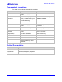

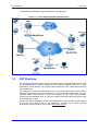


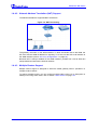

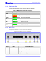


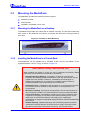

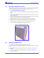
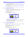
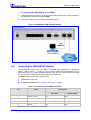
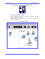
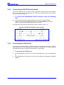

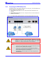
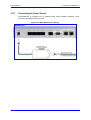


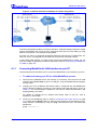
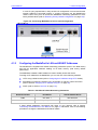
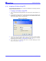


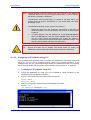
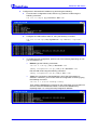
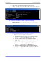
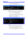
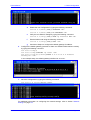
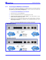
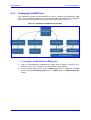
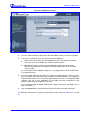


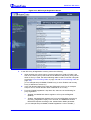

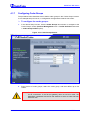
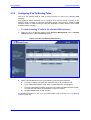
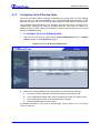
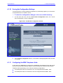


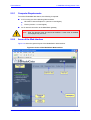
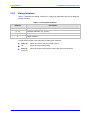


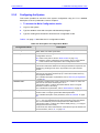
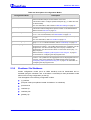
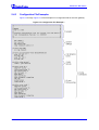
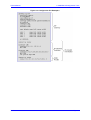
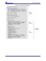


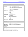
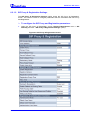
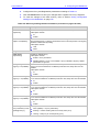
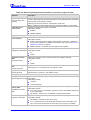
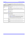

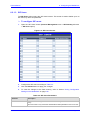

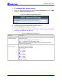

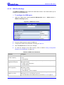
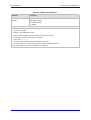
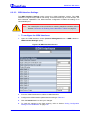
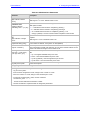
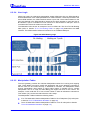

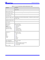
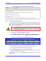

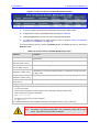

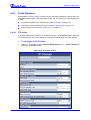
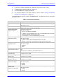

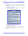

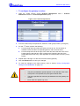

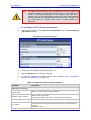


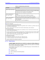
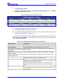

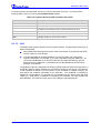
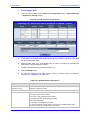


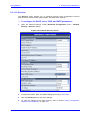

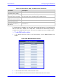
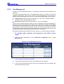

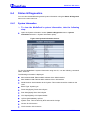
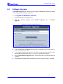

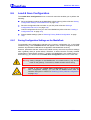

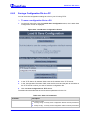

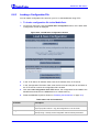


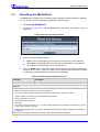
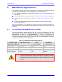

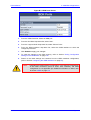


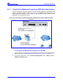

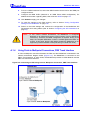
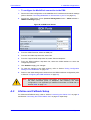
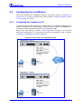
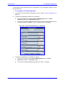


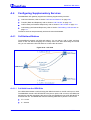

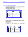


![LTRT-71403 MediaPack MGCP User Manual ver 4[1].](http://vs1.manualzilla.com/store/data/005760883_1-b98cf40cc1cd8cff0fa8bbf345d132db-150x150.png)