1
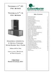
Tranquility®
High Efficiency
(TR) Series
Submittal Data
Models TRH/V 006 - 060
60Hz - HFC-410A
English Language/I-P Units
Submittal Data - I-P Units
Unit Designation:
Job Name:
Architect:
Engineer:
Contractor:
Performance Data
Cooling Capacity:
Btuh
EER:
Heating Capacity:
Btuh
COP:
Revised: 18 July, 2013
Ambient Air Temp:
°F
Entering Water Temp (Clg):
°F
Entering Air Temp (Clg):
°F
Entering Water Temp (Htg):
°F
Entering Air Temp (Htg):
°F
Airflow:
CFM
Fan Speed or Motor/RPM/Turns:
Operating Weight:
(lb)
Electrical Data
Power Supply:
ClimateMaster works continually to improve its products. As a result, the design and specifications of each
product at the time of order may be changed without notice and may not be as described herein. Please contact
ClimateMaster's Customer Service Department at 1-405-745-6000 for specific information on the current design and
specifications. Statements and other information contained herein are not express warranties and do not form the
basis of any bargain between the parties, but are merely ClimateMaster's opinion or commendation of its products.
The latest version of this document is available at climatemaster.com.
*LC516*
LC516
Revised: 18 July, 2013
Volts
PhaseHz
Minimum Circuit Ampacity:
Maximum Overcurrent Protection:
Tranquility®
High Efficiency
(TR) Series
Submittal Data
Models TRH/V 006 - 060
60Hz - HFC-410A
English Language/S-I Units
Submittal Data - S-I Units
Unit Designation:
Job Name:
Architect:
Engineer:
Contractor:
Performance Data
Cooling Capacity:
kW
EER:
Heating Capacity:
kW
COP:
Revised: 18 July, 2013
Ambient Air Temp:
°C
Entering Water Temp (Clg):
°C
Entering Air Temp (Clg):
°C
Entering Water Temp (Htg):
°C
Entering Air Temp (Htg):
°C
Airflow:
l/s
Fan Speed or Motor/RPM/Turns:
Operating Weight:
(kg)
Electrical Data
Power Supply:
ClimateMaster works continually to improve its products. As a result, the design and specifications of each
product at the time of order may be changed without notice and may not be as described herein. Please contact
ClimateMaster's Customer Service Department at 1-405-745-6000 for specific information on the current design and
specifications. Statements and other information contained herein are not express warranties and do not form the
basis of any bargain between the parties, but are merely ClimateMaster's opinion or commendation of its products.
The latest version of this document is available at climatemaster.com.
*LC516*
LC516
Revised: 18 July, 2013
Volts
PhaseHz
Minimum Circuit Ampacity:
Maximum Overcurrent Protection:
TR Series 60Hz - HFC-410A Submittal Data
Eng/I-P
Table of Contents
*Page Number
Unit Features . . . . . . . . . . . . . . . . . . . . . . . . . . . . . . . . . . . . . . . . . . . . . . . . . . . . . . . . . . . 4
Selection Procedure . . . . . . . . . . . . . . . . . . . . . . . . . . . . . . . . . . . . . . . . . . . . . . . . . . . . . . 5
TR Series Nomenclature. . . . . . . . . . . . . . . . . . . . . . . . . . . . . . . . . . . . . . . . . . . . . . . . . . . . 7
Performance Data – AHRI/ASHRAE/ISO 13256-1 . . . . . . . . . . . . . . . . . . . . . . . . . . . . . . . . . . 8
Performance Data – Selection Notes. . . . . . . . . . . . . . . . . . . . . . . . . . . . . . . . . . . . . . . . . . . 9
Performance Data – TR H/V 006 . . . . . . . . . . . . . . . . . . . . . . . . . . . . . . . . . . . . . . . . . . . . . 10
Performance Data – TR H/V 009 . . . . . . . . . . . . . . . . . . . . . . . . . . . . . . . . . . . . . . . . . . . . . 11
Performance Data – TR H/V 012 . . . . . . . . . . . . . . . . . . . . . . . . . . . . . . . . . . . . . . . . . . . . . 12
Performance Data – TR H/V 015 . . . . . . . . . . . . . . . . . . . . . . . . . . . . . . . . . . . . . . . . . . . . . 13
Performance Data – TR H/V 018 . . . . . . . . . . . . . . . . . . . . . . . . . . . . . . . . . . . . . . . . . . . . . 14
Performance Data – TR H/V 024 . . . . . . . . . . . . . . . . . . . . . . . . . . . . . . . . . . . . . . . . . . . . . 15
Performance Data – TR H/V 030 . . . . . . . . . . . . . . . . . . . . . . . . . . . . . . . . . . . . . . . . . . . . . 16
Performance Data – TR H/V 036 . . . . . . . . . . . . . . . . . . . . . . . . . . . . . . . . . . . . . . . . . . . . . 17
Performance Data – TR H/V 042 . . . . . . . . . . . . . . . . . . . . . . . . . . . . . . . . . . . . . . . . . . . . . 18
Performance Data – TR H/V 048 . . . . . . . . . . . . . . . . . . . . . . . . . . . . . . . . . . . . . . . . . . . . . 19
Performance Data – TR H/V 060 . . . . . . . . . . . . . . . . . . . . . . . . . . . . . . . . . . . . . . . . . . . . . 20
Correction Tables – Entering air temperature . . . . . . . . . . . . . . . . . . . . . . . . . . . . . . . . . . . 21
Correction Tables – Antifreeze and Water Pressure Drop Adder for Options . . . . . . . . . . . . 22
Blower Performance Data – Standard Unit. . . . . . . . . . . . . . . . . . . . . . . . . . . . . . . . . . . . . 23
Blower Performance Data with ClimaDry® . . . . . . . . . . . . . . . . . . . . . . . . . . . . . . . . . . . . . . 25
ClimaDry® II Option – Benefits and Application. . . . . . . . . . . . . . . . . . . . . . . . . . . . . . . . . . . 27
ClimaDry® II Option – Sequence of Operation. . . . . . . . . . . . . . . . . . . . . . . . . . . . . . . . . . . . 29
Physical Data . . . . . . . . . . . . . . . . . . . . . . . . . . . . . . . . . . . . . . . . . . . . . . . . . . . . . . . . . . 31
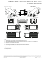
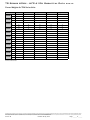
TR - Horizontal – Dimensional Data. . . . . . . . . . . . . . . . . . . . . . . . . . . . . . . . . . . . . . . . . . . 32
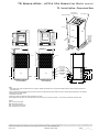
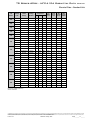
TR - Vertical Upflow – Dimensional Data . . . . . . . . . . . . . . . . . . . . . . . . . . . . . . . . . . . . . . . 34
Corner Weights for TRH Series Units. . . . . . . . . . . . . . . . . . . . . . . . . . . . . . . . . . . . . . . . . 36
Electrical Data – Standard Unit. . . . . . . . . . . . . . . . . . . . . . . . . . . . . . . . . . . . . . . . . . . . . 37
Electrical Data – High Static Blower . . . . . . . . . . . . . . . . . . . . . . . . . . . . . . . . . . . . . . . . . 38
Electrical Data – Internal Secondary Pump. . . . . . . . . . . . . . . . . . . . . . . . . . . . . . . . . . . . . 39
Electrical Data – High Static with Internal Secondary Pump . . . . . . . . . . . . . . . . . . . . . . . . 40
Electrical Data with ClimaDry®. . . . . . . . . . . . . . . . . . . . . . . . . . . . . . . . . . . . . . . . . . . . . . 41
Electrical Data – ClimaDry® & High Static Fan. . . . . . . . . . . . . . . . . . . . . . . . . . . . . . . . . . . 42
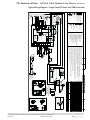
TR Series Wiring Diagram Matrix. . . . . . . . . . . . . . . . . . . . . . . . . . . . . . . . . . . . . . . . . . . . . 43
Typical Wiring Diagram – Single Phase TR with ClimaDry® . . . . . . . . . . . . . . . . . . . . . . . . . . . 44
Typical Wiring Diagram – Single Phase TR Units with CXM Controller . . . . . . . . . . . . . . . . . . 45
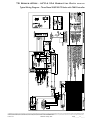
Typical Wiring Diagram – Single Phase TR Units with DXM Controller. . . . . . . . . . . . . . . . . . 46
Typical Wiring Diagram – Three Phase 208/230V TR Units with CXM Controller. . . . . . . . . . . 47
Typical Wiring Diagram – Three Phase 208/230V TR Units with DXM Controller . . . . . . . . . . 48
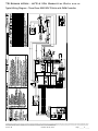
Typical Wiring Diagram – Three Phase 460/575V TR Units with CXM Controller. . . . . . . . . . . 49
Typical Wiring Diagram – Three Phase 460/575V TR Units with DXM Controller. . . . . . . . . . . 50
Typical Wiring Diagram – Three Phase 460/575V TR Units with CXM And LON Controller. . . . 51
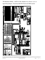
Typical Wiring Diagram – Three Phase 460/575V TR Units with DXM & LON Controller. . . . . . 52
Typical Wiring Diagram – Three Phase 460/575V TR Units with CXM & MPC Controller. . . . . . 53
Typical Wiring Diagram – Three Phase 460/575V TR Units with DXM & MPC Controller. . . . . . 54
Engineering Specifications . . . . . . . . . . . . . . . . . . . . . . . . . . . . . . . . . . . . . . . . . . . . . . . . . 55
Revision History . . . . . . . . . . . . . . . . . . . . . . . . . . . . . . . . . . . . . . . . . . . . . . . . . . . . . . . . 64
*Document page number is shown next to part number (e.g. LC516 - 3 = page 3). Since not all pages are typically
used in the submittals process, the page number in the lower right corner can still be used (page ____of_____).
ClimateMaster works continually to improve its products. As a result, the design and specifications of each product at the time of order may be changed without notice and may not be as described herein. Please contact ClimateMaster's Customer
Service Department at 1-405-745-6000 for specific information on the current design and specifications. Statements and other information contained herein are not express warranties and do not form the basis of any bargain between the parties,
but are merely ClimateMaster's opinion or commendation of its products. The latest version of this document is available at climatemaster.com.
LC516 - 3
Revised: 18 July, 2013
Page ______ of ______
TR Series 60Hz - HFC-410A Submittal Data
Eng/I-P
Unit Features
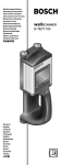
THE Tranquility® TR SERIES
UNIT FEATURES
The award winning Tranquility Series raises the bar
for water-source heat pump efficiencies, features and
application flexibility. Not only does the Tranquility®
TR exceed ASHRAE 90.1 efficiencies, but it also uses
EarthPure® HFC-410A zero ozone depletion refrigerant,
making it an extremely environmentally-friendly option.
Tranquility® TR is eligible for additional LEED (Leadership
in Energy and Environmental Design) points because of
the “green” technology design.
•Sizes 006 (1/2 ton, 1.76 kW) through 060 (5 tons, 17.6 kW)
•EarthPure® HFC-410A refrigerant
•Exceeds ASHRAE 90.1 efficiencies
•Galvanized steel construction with attractive matte black
epoxy powder coat paint front access panels.
•Epoxy powder painted galvanized steel drain pan
•Sound absorbing glass fiber insulation
•Unique double isolation compressor mounting for quiet
operation
•Insulated divider and separate compressor/air handler
compartments
•Scroll compressors (rotary for size 018 and below)
•TXV metering device
•Microprocessor controls standard (optional DXM and/or
DDC controls)
•Field convertible discharge air arrangement for
horizontal units
•PSC three-speed fan motor (2 speed for 575 volt)
•Internally trapped condensate drain line (vertical
units only)
•Unit Performance Sentinel performance monitoring
system
•Eight Safeties Standard
•Extended range (20 to 120°F, -6.7 to 48.9°C) capable
®
Available in sizes from 1/2 ton (1.76 kW) through 5 tons
(17.6 kW) with multiple cabinet options (vertical upflow
and horizontal) the Tranquility® TR offers a wide range of
units for most any installation. The Tranquility® TR has an
extended range refrigerant circuit, capable of geothermal
ground loop applications (with optional extended range
insulation) as well as boiler-tower water loop applications.
Standard features include: scroll compressors (rotary for
size 018 and below), microprocessor controls, galvanized
steel cabinet, epoxy powder painted front access panel,
galvanized steel with epoxy powder painted drain pan
and sound absorbing air handler insulation are just some
of the features of the Tranquility® TR Series.
ClimateMaster’s exclusive double isolation compressor
mounting system makes the Tranquility® TR one of the
quietest units on the market. Compressors are mounted
on specially engineered sound-tested EPDM grommets
or spring vibration isolators to a heavy gauge mounting
plate, which is further isolated from the cabinet base
with rubber grommets for maximized vibration and
sound attenuation. The easy access control box and
large access panels make installing and maintaining the
unit easier than other water-source heat pumps currently
in production.
Options such as coated air coil, DDC controls, high
efficiency pleated MERV 11 two-inch (51mm) air filter
or one-inch (25mm) pleated MERV 8 air filters allow
customized design solutions. Optional high static fan
motor expands the operating range and helps overcome
some of the challenges associated with ductwork for
retrofit installations. A Cupro-nickel water-coil and sound
absorbing UltraQuiet package are options that make a
great unit even better.
AVAILABLE OPTIONS
•High static blowers
•LonWorks, BACnet, Modbus and Johnson N2
compatibility options for DDC controls
•Cupro-nickel water-coil
•Sound absorbing UltraQuiet package
•Coated air coil
•Hot water generator
•Secondary circulating pump
•Water balancing valve
•ClimaDry® modulating reheat
The Tranquility® TR Series Water-Source Heat Pumps
are designed to meet the challenges of today’s HVAC
demands with one of the most innovative products
available on the market.
ClimateMaster works continually to improve its products. As a result, the design and specifications of each product at the time of order may be changed without notice and may not be as described herein. Please contact ClimateMaster's Customer
Service Department at 1-405-745-6000 for specific information on the current design and specifications. Statements and other information contained herein are not express warranties and do not form the basis of any bargain between the parties,
but are merely ClimateMaster's opinion or commendation of its products. The latest version of this document is available at climatemaster.com.
LC516 - 4
Revised: 18 July, 2013
Page ______ of ______
TR Series 60Hz - HFC-410A Submittal Data
Eng/I-P
Selection Procedure
Reference Calculations
Heating
Cooling
HE
LWT = EWT GPM x 500
HC
CFM x1.08
LAT = EAT +
LWT = EWT +
HR
GPM x 500
LAT (DB) = EAT (DB) -
LC = TC - SC
SC
CFM x1.08
S/T =
SC
TC
Legend and Glossary of Abbreviations
BTUH = BTU( British Thermal Unit) per hour
CFM = airflow, cubic feet/minute
COP = coefficient of performance = BTUH output/BTUH input
DB = dry bulb temperature (°F)
EAT = entering air temperature, Fahrenheit (dry bulb/wet bulb)
EER = energy efficiency ratio = BTUH output/Watt input
MPT = male pipe thread
ESP = external static pressure (inches w.g.)
EWT = entering water temperature
GPM = water flow in U.S. gallons/minute
HE = total heat of extraction, BTUH
HC = air heating capacity, BTUH
HR = total heat of rejection, BTUH
HWC
FPT
KW
LAT
LC
LWT
MBTUH
S/T
SC
TC
WB
WPD
= hot water generator (desuperheater) capacity, Mbtuh
= female pipe thread
= total power unit input, kilowatts
= leaving air temperature, °F
= latent cooling capacity, BTUH
= leaving water temperature, °F
= 1000 BTU per hour
= sensible to total cooling ratio
= sensible cooling capacity, BTUH
= total cooling capacity, BTUH
= wet bulb temperature (°F)
= waterside pressure drop (psi & ft. of hd.)
To convert Inch-Pound
(English)
to SIinch-pound
(Metric)
Conversion
Table - to
convert
(English) to S-I (Metric)
Air Flow
Water Flow
Ext Static Pressure
Water Pressure Drop
Airflow (L/s) = CFM x 0.472
Water Flow (L/s) = gpm x 0.0631
ESP (Pa) = ESP (in of wg) x 249
PD (kPa) = PD (ft of hd) x 2.99
Entering Air Correction Tables
Cooling Corrections
Ent Air
WB ϒF
Total Clg
Cap
70
75
80
80.6
60
0.852
0.828
0.980
1.097
65
0.974
0.595
0.808
1.004
66.2
1.000
0.539
0.767
67
1.004
0.501
0.740
70
1.034
0.636
75
Heating Corrections
Sens Clg Cap Multiplier - Entering DB ϒF
1.069
Heat of
Ext
0.996
0.878
*
0.998
0.979
*
*
1.000
1.000
1.233
1.276
1.002
1.010
1.220
1.005
1.029
75
0.980
1.037
0.960
1.058
80
0.967
1.063
0.934
1.129
*
*
1.017
1.194
*
0.967
1.000
1.152
0.939
0.955
1.124
0.810
0.844
1.016
1.136
0.826
Power
*
95
0.612
Htg Cap
Heat of
Rej
90
0.514
Ent Air
DB ϒF
Power
85
0.973
1.127
1.010
60
1.059
0.947
1.100
65
1.019
0.981
1.032
68
1.000
1.000
1.000
70
0.995
1.010
0.989
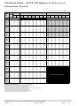
Entering air corrections should be multiplied directly to unit performance data to derive performance at entering air condition other
than ARI/ISO/ASHRAE 13256-1
ARI/ISO/ASHRAE 13256-1 uses entering air conditions of Clg- 80.6ϒF DB/66.2ϒF WB and Htg- 68ϒF DB/59ϒF WB shown in bold
Discontinued Standards ARI 320, 325, and 330 used entering air conditions of Clg- 80ϒF DB/67ϒF WB and Htg- 70ϒF DB
Air Flow Correction Table
Airflow
Cooling
Heating
CFM Per Ton
of Clg
% of
Nominal
Total Cap
Sens Cap
Power
Heat of Rej
Htg Cap
Power
Heat of Ext
300
75%
1.019
0.902
0.964
1.007
0.957
1.061
0.922
325
81%
1.013
0.928
0.976
1.003
0.968
1.040
0.946
350
88%
1.007
0.953
0.988
1.000
0.979
1.020
0.970
375
94%
1.004
0.977
0.994
1.000
0.989
1.010
0.985
ClimateMaster
to improve its
products. As a result,
and specifications1.000
of each product at1.000
the time of order
may be changed1.000
without notice and may not be as described herein. Please contact ClimateMaster's Customer
400 works continually
100%
1.000
1.000the design1.000
1.000
Service Department at 1-405-745-6000 for specific information on the current design and specifications. Statements and other information contained herein are not express warranties and do not form the basis of any bargain between the parties,
but are merely
opinion or commendation
of its1.023
products. The latest
version of this1.000
document is available
425 ClimateMaster's
106%
0.998
1.006
1.011at climatemaster.com.
0.997
1.015
LC516 - 5
450
113%
0.997
1.047
1.012
18 July,0.994
2013
1.000Revised:
1.021
1.030
Page ______ of ______
TR Series 60Hz - HFC-410A Submittal Data
Eng/I-P
Selection Procedure
Step 1 Determine the actual heating and cooling loads at the
desired dry bulb and wet bulb conditions.
Step 2 Obtain the following design parameters: Entering water
temperature, water flow rate in GPM, air flow in CFM,
water flow pressure drop and design wet and dry bulb
temperatures. Air flow CFM should be between 300 and
450 CFM per ton. Unit water pressure drop should be
kept as close as possible to each other to make water
balancing easier. Go to the appropriate tables and find
the proper indicated water flow and water temperature.
Step 3 Select a unit based on total and sensible cooling
conditions. Select a unit which is closest to, but no
larger than, the actual cooling load.
Step 4 Enter tables at the design water flow and water
temperature. Read the total and sensible cooling
capacities (Note: interpolation is permissible,
extrapolation is not).
Step 5 Read the heating capacity. If it exceeds the design
criteria it is acceptable. It is quite normal for watersource heat pumps to be selected on cooling capacity
only since the heating output is usually greater than the
cooling capacity.
Step 6 Determine the correction factors associated with the
variable factors of dry bulb and wet bulb.
Corrected Total Cooling = tabulated total cooling x wet
bulb correction.
Corrected Sensible Cooling = tabulated sensible
cooling x wet/dry bulb correction.
Step 7 Compare the corrected capacities to the load
requirements. Normally if the capacities are within 10%
of the loads, the equipment is acceptable. It is better
to undersize than oversize, as undersizing improves
humidity control, reduces sound levels and extends the
life of the equipment.
Step 8 When completed, calculate water temperature rise
and assess the selection. If the units selected are not
within 10% of the load calculations, then review what
effect changing the GPM, water temperature and/or air
flow and air temperature would have on the corrected
capacities. If the desired capacity cannot be achieved,
select the next larger or smaller unit and repeat the
procedure. Remember, when in doubt, undersize
slightly for best performance.
Example Equipment Selection For Cooling
Step 1 Load Determination:
Assume we have determined that the appropriate cooling load
at the desired dry bulb 80°F and wet bulb 65°F conditions is as
follows:
Total Cooling...........................................................24,500 BTUH
Sensible Cooling.....................................................21,800 BTUH
Entering Air Temp......................80°F Dry Bulb / 65°F Wet Bulb
Step 2 Design Conditions:
Similarly, we have also obtained the following design
parameters:
Entering Water Temp............................................................90°F
Water Flow (Based upon 10°F rise in temp.)................6.0 GPM
Air Flow...........................................................................750 CFM
Step 3, 4 & 5 HP Selection:
After making our preliminary selection (TR024), we enter the
tables at design water flow and water temperature and read
Total Cooling, Sens. Cooling and Heat of Rej. capacities:
Total Cooling...........................................................23,400 BTUH
Sensible Cooling.....................................................17,500 BTUH
Heat of Rejection....................................................30,200 BTUH
Step 6 & 7 Entering Air and Airflow Corrections:
Next, we determine our correction factors.
Table
Ent Air Air Flow
Corrected
Corrected Total Cooling = 23,400 x 0.9681 x 0.9947 = 22,533
Corrected Sens Cooling = 17,500 x 1.1213 x 1.0222 = 20,058
Corrected Heat of Reject = 30,200 x 0.9747 x 0.9668 = 28,459
Step 8 Water Temperature Rise Calculation & Assessment:
Actual Temperature Rise......................................................9.5°F
When we compare the Corrected Total Cooling and Corrected
Sensible Cooling figures with our load requirements stated
in Step 1, we discover that our selection is within +/- 10% of
our sensible load requirement. Furthermore, we see that our
Corrected Total Cooling figure is within 1,000 Btuh the actual
indicated load.
ClimateMaster works continually to improve its products. As a result, the design and specifications of each product at the time of order may be changed without notice and may not be as described herein. Please contact ClimateMaster's Customer
Service Department at 1-405-745-6000 for specific information on the current design and specifications. Statements and other information contained herein are not express warranties and do not form the basis of any bargain between the parties,
but are merely ClimateMaster's opinion or commendation of its products. The latest version of this document is available at climatemaster.com.
LC516 - 6
Revised: 18 July, 2013
Page ______ of ______
TR Series 60Hz - HFC-410A Submittal Data
Eng/I-P
TR Series Nomenclature
1
MODEL TYPE
2
TR
3
H
4 5 6
7
036
A
8
G
9
C
10
3
11
0
12
C
13
L
14
15
B
S
TR = TRANQUILITY HIGH EFFICIENCY 410A
®
SUPPLY AIR OPTIONS
CONFIGURATION
H = HORIZONTAL
V = VERTICAL
S = STANDARD
B = BACK DISCHARGE, HORIZONTAL ONLY
Y = BACK DISCHARGE, HIGH STATIC
HORIZONTAL 015-060 COMMERCIAL ONLY
T = TOP DISCHARGE, VERTICAL ONLY
V = TOP DISCHARGE, HIGH STATIC
VERTICAL 015-060 COMMERCIAL ONLY
S = STRAIGHT DISCHARGE, HORIZONTAL ONLY
Z = STRAIGHT DISCHARGE, HIGH STATIC
HORIZONTAL 015-060 COMMERCIAL ONLY
UNIT SIZE
006 - E,G
009 - E,G
012 - E,G
015 - E,G
018 - E,G
024 - E,G,H,F
030 - E,G,H,F
036 - E,G,H,F
042 - G,H,F,N
048 - G,H,F,N
060 - G,H,F,N
AVAILABLE
VOLTAGES
RETURN AIR OPTIONS
L = LEFT RETURN
R = RIGHT RETURN
V = LEFT RETURN, STAINLESS STEEL DRAIN PAN
W = RIGHT RETURN, STAINLESS STEEL DRAIN PAN
HEAT EXCHANGER OPTIONS
REVISION LEVEL
Non Coated Air Coil Tin-plated Air Coil
Copper Cupro-nickel Copper Cupro-nickel
Standard
C
N
A
J
Motorized Valve
T
S
U
W
®
E
ClimaDry
P
D
F
A = CURRENT REVISION
VOLTAGE
G = 208-230/60/1
E = 265/60/1
H = 208-230/60/3
F = 460/60/3
N = 575/60/3
WATER CIRCUIT OPTIONS
0 = None
2 = HWG (Coil Only)
5 = Internal Secondary Pump
6 = HWG (Coil Only) w/Auto Flow Regulator 2.5 GPM/Ton
7 = HWG (Coil Only) w/Auto Flow Regulator 3.0 GPM/Ton
8 = Auto Flow Regulator 2.5 GPM/Ton
9 = Auto Flow Regulator 3.0 GPM/Ton
CONTROLS
C = CXM
D = DXM
L = CXM w/LON
M = DXM w/LON
N = CXM w/MPC
P = DXM w/MPC
CABINET INSULATION
1 = EXTENDED RANGE
2 = EXTENDED RANGE w/ULTRA QUIET
3 = STANDARD RANGE
4 = STANDARD RANGE w/ULTRA QUIET
ClimaDry® II Option Notes:
1. Unit must have DXM control option. 460 volt unit units require a four wire power supply with neutral.
2. ClimaDry® II may not be combined with motorized water valve, internal secondary circulating pump, or automatic flow
regulator options.
3. Unit minimum entering air temperature while in the dehumidification, cooling, or continuous fan modes is 70ºF DB/61ºF WB. Operation below this minimum may result in nuisance faults.
4. A thermostat with dehumidification mode or thermostat and separate humidistat/dehumidistat is required for activation and
control of ClimaDry® II.
5. 575 volt units are not eligible for ClimaDry® II.
ClimateMaster works continually to improve its products. As a result, the design and specifications of each product at the time of order may be changed without notice and may not be as described herein. Please contact ClimateMaster's Customer
Service Department at 1-405-745-6000 for specific information on the current design and specifications. Statements and other information contained herein are not express warranties and do not form the basis of any bargain between the parties,
but are merely ClimateMaster's opinion or commendation of its products. The latest version of this document is available at climatemaster.com.
LC516 - 7
Revised: 18 July, 2013
Page ______ of ______
TR Series 60Hz - HFC-410A Submittal Data
Eng/I-P
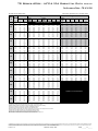
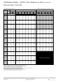
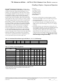
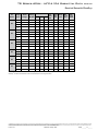
Performance Data – AHRI/ASHRAE/ISO 13256-1
ASHRAE/AHRI/ISO 13256-1. English (I-P) Units
Water Loop Heat Pump
Model
Cooling 86°F
Ground Water Heat Pump
Heating 68°F
Cooling 59°F
Capacity
EER
Capacity
Capacity
COP
Btuh
Btuh/W
Btuh
Btuh
Ground Loop Heat Pump
Heating 50°F
EER
Btuh/W
Capacity
Btuh
Cooling 77°F
COP
Capacity
Btuh
EER
Btuh/W
Heating 32°F
Capacity
COP
Btuh
TR-006
5,800
13.2
7,500
4.7
6,900
21.1
6,200
4.0
6,200
15.4
4,900
3.4
TR-009
8,800
13.4
11,600
4.2
10,100
21.0
9,800
3.9
9,300
15.7
7,900
3.4
TR-012
11,700
13.5
15,200
4.3
13,700
20.8
12,500
3.8
12,000
14.9
9,900
3.2
TR-015
14,500
15.4
17,300
5.0
16,800
24.5
14,400
4.4
15,000
17.2
11,100
3.6
TR-018
17,300
14.3
21,500
5.0
20,600
24.2
17,200
4.4
18,400
16.3
13,900
3.4
TR-024
23,700
13.4
28,500
4.7
26,700
20.9
24,000
4.1
24,900
15.4
18,500
3.3
TR-030
28,100
13.4
35,100
4.6
31,700
20.1
29,600
4.1
28,900
15.1
23,400
3.4
TR-036
34,500
13.5
45,200
4.4
38,700
20.7
37,500
4.0
35,300
14.9
29,600
3.3
TR-042
40,100
13.1
52,700
4.3
45,900
19.6
44,000
3.8
40,500
14.4
34,300
3.2
TR-048
47,700
13.3
55,900
4.7
54,300
20.5
46,500
4.1
49,000
14.7
36,400
3.4
TR-060
59,400
13.4
77,000
4.3
66,600
19.9
64,000
3.8
60,100
14.8
50,500
3.1
Cooling capacities based upon 80.6°F DB, 66.2°F WB entering air temperature.
Heating capacities based upon 68°F DB, 59°F WB entering air temperature.
All ratings based upon operation at lower voltage of dual voltage rated models.
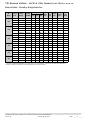
ASHRAE/AHRI/ISO 13256-1. Metric (S-I) Units
Water Loop Heat Pump
Model
Cooling 30°C
Ground Water Heat Pump
Heating 20°C
Capacity
kW
EER
W/W
TR-006
1.70
3.9
2.20
4.7
TR-009
2.58
3.9
3.40
TR-012
3.43
4.0
4.45
TR-015
4.25
4.5
TR-018
5.07
TR-024
6.94
TR-030
TR-036
TR-042
Cooling 15°C
Capacity
Capacity
COP
kW
kW
Ground Loop Heat Pump
Heating 10°C
EER
W/W
Capacity
kW
2.02
6.2
4.2
2.96
4.3
4.01
5.07
5.0
4.2
6.30
3.9
8.35
8.23
3.9
10.28
10.11
4.0
13.24
11.75
3.8
TR-048
13.98
TR-060
17.40
Cooling 25°C
Heating 0°C
COP
Capacity
kW
EER
W/W
Capacity
kW
COP
1.82
4.0
1.82
4.5
1.44
3.4
6.2
2.87
3.9
2.72
4.6
2.31
3.4
6.1
3.66
3.8
3.52
4.4
2.90
3.2
4.92
7.2
4.22
4.4
4.39
5.0
3.25
3.6
5.0
6.04
7.1
5.04
4.4
5.39
4.8
4.07
3.4
4.7
7.82
6.1
7.03
4.1
7.30
4.5
5.42
3.3
4.6
9.29
5.9
8.67
4.1
8.47
4.4
6.86
3.4
4.4
11.34
6.1
10.99
4.0
10.34
4.4
8.67
3.3
15.44
4.3
13.45
5.7
12.89
3.8
11.87
4.2
10.05
3.2
3.9
16.38
4.7
15.91
6.0
13.62
4.1
14.36
4.3
10.67
3.4
3.9
22.56
4.3
19.51
5.8
18.75
3.8
17.61
4.3
14.80
3.1
Cooling capacities based upon 27°C DB, 19°C WB entering air temperature.
Heating capacities based upon 20°C DB, 15°C WB entering air temperature.
All ratings based upon operation at lower voltage of dual voltage rated models.
ClimateMaster works continually to improve its products. As a result, the design and specifications of each product at the time of order may be changed without notice and may not be as described herein. Please contact ClimateMaster's Customer
Service Department at 1-405-745-6000 for specific information on the current design and specifications. Statements and other information contained herein are not express warranties and do not form the basis of any bargain between the parties,
but are merely ClimateMaster's opinion or commendation of its products. The latest version of this document is available at climatemaster.com.
LC516 - 8
Revised: 18 July, 2013
Page ______ of ______
TR Series 60Hz - HFC-410A Submittal Data
Eng/I-P
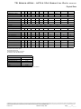
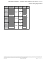
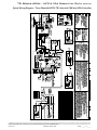
Performance Data – Selection Notes
For operation in the shaded area when water is used in lieu of
an antifreeze solution, the LWT (Leaving Water Temperature)
WPD
Cooling
EAT such
80/67°F
Heating - EAT 70°F
must be calculated.
Flow must be maintained
to a-level
EWT
that theGPM
LWT is maintained above
40°F
[4.4°C]
when
the
Sens/
Airflow
Airflow
°F
Tot
PSI clipped
FT (see
TC below).
SC Otherwise,
kW
HR
EER
HC
kW
HE
LAT COP
JW3 jumper is not
example
CFM
CFM
Ratio
appropriate levels of a proper antifreeze solution should be
20
7.0
4.5
10.30000000
710
11.6
1.05
8.2
85.1
3.25
20
Operation of
not40ºF
recommended
used
in systems
with leaving
water
temperatures
[4.4°C]
20
7.0
4.5
10.3
0000000
825
11.7
1.02
8.4
83.2
3.38
30
1.2
710 13.61.0910.187.83.66
or below3.5
and the
JW32.8
jumper620
should22.214.00.630.5824.138.3
be clipped. This is due
30
3.5 1.2
725
22.514.70.650.5924.438.3
825 13.81.0610.385.53.81
to the potential
of the2.8
refrigerant
temperature
being as low as
30 5.8 2.9 6.6 620 22.414.00.630.5724.339.2 710 14.21.0910.788.53.81
30 [0°C]
32°F
with 2.9
40°F [4.4°C]
which
may lead to a nuisance
30
5.8
6.6LWT,
725
22.714.70.650.5824.739.2
825 14.41.0610.986.13.97
30
7.0
4.1
9.4 of
620
22.514.00.620.5624.439.8
710 14.41.0910.988.83.86
cutout due
to the
activation
the Low
Temperature Protection.
30
7.0
4.1
9.4 725
22.814.70.650.5724.739.8
825 14.61.0611.186.34.02
JW3 should
never
be clipped
for standard
range equipment or
40 3.5 1.1 2.5 620 22.915.10.660.6525.135.3 710 16.11.1512.390.94.08
systems
without
antifreeze.
40 3.5 1.1 2.5 725 23.315.80.680.6625.535.3 825 16.21.1212.688.24.25
40 5.8 2.6 5.9 620 23.115.10.650.6125.237.9 710 16.71.1513.091.84.25
40
40
5.8 2.6 5.9 725 23.415.90.680.6225.537.9 825 16.91.1213.389.04.42
Example:
40 7.0 3.6 8.4 620 23.215.10.65 0.6 25.238.3 710 16.91.1613.292.14.30
40 7.0 3.6 8.4 725 23.515.90.680.6125.638.3 825 17.11.1213.589.24.47
At 50°F EWT
(Entering
Water 620
Temperature)
and 1.5 GPM/ton, a
50
3.5
1.0 2.3
22.715.40.680.7425.230.7
710 18.31.1814.593.94.56
50
3.5
725
23.016.20.700.7525.630.7
825 18.51.1414.890.84.75
3 ton unit
has a1.0
HE of 2.3
22,500 Btuh.
To
calculate LWT, rearrange
50
5.8
the
for2.4
HE as 5.6
follows:620 22.915.50.670.6925.333.4 710 19.11.1815.294.84.73
50 formula
50
5.8 2.4 5.6 725 23.316.30.700.7025.633.4 825 19.31.1515.591.64.93
50 7.0 3.4 7.9 620 23.015.50.670.6725.334.1 710 19.31.1815.495.14.78
HE = TD7.0
x GPM3.4
x 500,7.9
where 725
HE = Heat
of Extraction (Btuh);
50
23.316.30.700.6825.634.1
825 19.51.1515.791.94.98
60
3.5 1.0
2.2 620
710 20.41.2116.596.64.93
TD = temperature
difference
(EWT -21.915.30.700.8524.825.9
LWT) and GPM = U.S.
60 3.5 1.0 2.2 725 22.216.10.730.8625.125.9 825 20.61.1816.893.25.13
Gallons per Minute.
60 5.8 2.3 5.2 620 22.415.50.690.7825.128.6 710 21.21.2217.397.75.10
60
60
5.8 2.3 5.2 725 22.716.30.720.8025.428.6 825 21.51.1817.694.15.31
TD = HE7.0
/ (GPM
x 500)7.4 620 22.515.50.690.7725.129.4 710 21.51.2217.598.05.15
60
3.2
60 7.0 3.2 7.4 725 22.916.30.710.7825.529.4 825 21.71.1917.894.35.36
70 3.5 0.9 2.1 620 20.714.80.720.9724.021.4 710 22.41.2318.499.25.35
TD = 22,500 / (4.5 x 500)
70 3.5 0.9 2.1 725 21.015.60.740.9824.321.4 825 22.71.1918.895.45.57
70 5.8 2.1 4.9 620 21.415.10.710.9024.423.8 710 23.31.2419.3100.45.52
70= 10°F
TD
70
5.8 2.1 4.9 725 21.715.90.730.9124.823.8 825 23.51.2019.696.45.75
70 7.0 3.0 7.0 620 21.615.20.710.8824.624.5 710 23.51.2419.5100.75.57
70
7.0
3.0 7.0 725 21.916.00.730.8924.924.5 825 23.81.2019.996.75.80
LWT = EWT
- TD
80 3.5 0.8 1.9 620 19.314.20.731.1023.117.5 710 24.41.2520.3101.85.73
80 3.5 0.8 1.9 725 19.614.90.761.1223.417.5 825 24.61.2120.797.75.97
LWT = 50
- 10 =2.0
40°F 4.6 620 20.114.50.721.0323.619.5 710 25.31.2621.2103.05.90
80
5.8
80
80
5.8 2.0 4.6 725 20.415.30.751.0423.919.5 825 25.61.2221.698.76.15
80
7.0 2.8
6.5
710
5.95
In this example,
as long
as the620
EWT 20.314.60.721.0123.720.1
does not fall below 50°F, the system will operate
as25.61.2621.5
designed. For EWTs 103.4
below 50°F,
80 7.0 2.8 6.5 725 20.615.40.751.0224.020.1 825 25.91.2221.999.06.20
flow rates
will be
required
(open
loop
systems, for example, require at least 2 GPM/ton
when EWT is below 50°F).
85
3.5
0.8
1.9
620
18.713.90.751.1822.715.9
710 25.31.2621.2
103.05.91
85 3.5 0.8 1.9 725 18.914.60.771.1923.015.9 825 25.61.2221.798.76.15
85 5.8 1.9 4.5 620 19.314.20.731.1023.117.5 710 26.31.2722.2104.36.08
85
85
5.8 1.9 4.5 725 19.614.90.761.1223.417.5 825 26.61.2322.699.96.33
85 7.0 2.7 6.3 620 19.514.30.731.0823.218.0 710 26.61.2722.5104.76.13
85 7.0 2.7 6.3 725 19.815.00.761.1023.618.0 825 26.91.2422.9100.26.38
90 3.5 0.8 1.8 620 18.013.70.761.2522.314.4 710 26.31.2722.2104.36.08
90 3.5 0.8 1.8 725 18.314.40.781.2722.614.4 825 26.61.2322.699.86.33
90 5.8 1.9 4.4 620 18.613.80.741.1822.615.8 710 27.31.2823.1105.66.25
90
90
5.8 1.9 4.4 725 18.914.60.771.2022.915.8 825 27.61.2423.6101.06.51
90 7.0 2.7 6.2 620 18.813.90.741.1622.716.3 710 27.61.2823.4106.06.30
90 7.0 2.7 6.2 725 19.114.70.771.1723.116.3 825 27.91.2523.9101.36.56
100 3.5 0.8 1.8 620 16.613.00.781.4121.411.7 0 0 0 0 0 0
100 3.5 0.8 1.8 725 16.813.70.811.4321.711.7 0 0 0 0 0 0
100 5.8 1.8 4.2 620 17.113.20.771.3421.712.7 0 0 0 0 0 0
100
100 5.8 1.8 4.2 725 17.413.80.801.3622.012.7 0 0 0 0 0 0
100 7.0 2.6 6.0 620 17.313.30.771.3221.813.1 0 0 0 0 0 0
100 7.0 2.6 6.0 725 17.513.90.791.3422.113.1 0 0 0 0 0 0
110
3.5
0.7
1.7
620
15.5
12.7
0.82
1.59
20.9
9.7000000
110
3.5
0.7
1.7
725
15.7
13.4
0.85
1.61
21.2
9.7000000
110 5.8 1.7 4.0 620 15.812.70.801.5321.010.3 0 0 0 0 0 0
110
not recommended
110 5.8 1.7 4.0 725 16.013.30.831.5521.310.3 0 Operation
0 0
0 0 0
110 7.0 2.5 5.7 620 16.012.70.801.5021.110.6 0 0 0 0 0 0
110 7.0 2.5 5.7 725 16.213.40.831.5221.410.6 0 0 0 0 0 0
120
3.5
0.7
1.6
620
14.5
12.6
0.87
1.84
20.8
7.9000000
120
3.5
0.7
1.6
725
14.7
13.3
0.90
1.86
21.1
7.9000000
120
5.8
1.7
3.9
620
14.8
12.5
0.85
1.73
20.7
8.6000000
120
120
5.8
1.7
3.9
725
15.0
13.2
0.88
1.76
21.0
8.6000000
120
7.0
2.4
5.5
620
14.9
12.5
0.84
1.71
20.7
8.7000000
120
7.0
2.4
5.5
725
15.1
13.2
0.87
1.73
21.0
8.7000000
higher
ClimateMaster works continually to improve its products. As a result, the design and specifications of each product at the time of order may be changed without notice and may not be as described herein. Please contact ClimateMaster's Customer
Service Department at 1-405-745-6000 for specific information on the current design and specifications. Statements and other information contained herein are not express warranties and do not form the basis of any bargain between the parties,
but are merely ClimateMaster's opinion or commendation of its products. The latest version of this document is available at climatemaster.com.
LC516 - 9
Revised: 18 July, 2013
Page ______ of ______
TR Series 60Hz - HFC-410A Submittal Data
Eng/I-P
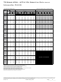
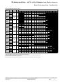
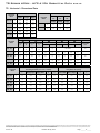
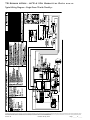
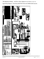
Performance Data – TR H/V 006
220 CFM Nominal (Rated) Airflow
EWT
GPM
°F
20
30
40
50
60
70
80
85
90
100
110
120
Performance capacities shown in thousands of Btuh
WPD
PSI
FT
Cooling - EAT 80/67°F
Airflow
CFM
TC
SC
Sens/Tot
Ratio
kW
Heating - EAT 70°F
HR
EER
Airflow
CFM
HC
kW
HE
LAT
COP
1.5
1.7
4.0
395170
4.3
0.49
2.7
93.3
2.6
Operation not recommended
1.5
1.7
4.0
525225
4.4
0.44
2.9
88.0
2.9
0.8 0.51.2 1707.4 4.20.57
0.288.426.4 1704.60.50 3.095.22.7
0.8 0.51.2 2257.7 4.80.62
0.298.726.4 2254.70.45 3.289.53.1
1.1 0.81.8 1707.4 4.10.55
0.268.328.5 1704.80.51 3.296.22.8
1.1 0.81.8 2257.7 4.60.60
0.278.628.5 2254.90.46 3.490.33.2
1.5 1.32.9 1707.3 4.00.54
0.258.229.2 1704.90.51 3.296.82.8
1.5 1.32.9 2257.6 4.50.59
0.268.529.2 2255.00.46 3.590.73.2
0.8 0.40.9 1707.3 4.30.59
0.318.323.2 1705.30.52 3.698.83.0
0.8 0.40.9 2257.6 4.80.64
0.338.723.2 2255.40.47 3.892.33.4
1.1 0.61.4 170 7.4 4.2 0.570.29 8.425.8 1705.50.53 3.8100.23.1
1.1 0.61.4 2257.7 4.80.62
0.308.725.8 2255.70.47 4.193.33.5
1.5 1.02.4 170 7.4 4.2 0.560.28 8.426.9 1705.70.53 3.9100.93.1
1.5 1.02.4 2257.7 4.70.61
0.298.726.9 2255.80.48 4.293.93.6
0.8 0.30.8 170 6.9 4.2 0.610.35 8.119.9 1706.00.54 4.2102.73.3
0.8 0.30.8 2257.2 4.80.66
0.368.519.9 2256.10.48 4.595.33.7
1.1 0.51.2 170 7.2 4.3 0.590.32 8.322.5 1706.30.55 4.5104.43.4
1.1 0.51.2 2257.5 4.80.64
0.338.622.5 2256.50.49 4.896.63.9
1.5 0.92.0 170 7.3 4.3 0.580.31 8.323.8 1706.50.55 4.6105.43.4
1.5 0.92.0 2257.6 4.80.63
0.328.723.8 2256.70.50 5.097.43.9
0.8 0.30.6 170 6.5 4.1 0.630.39 7.916.8 1706.70.56 4.9106.73.5
0.8 0.30.6 2256.8 4.70.69
0.408.216.8 2256.90.50 5.298.44.0
1.1 0.51.0 170 6.9 4.2 0.610.36 8.119.1 1707.10.57 5.2108.63.7
1.1 0.51.0 2257.1 4.80.67
0.378.419.1 2257.30.51 5.599.94.2
1.5 0.81.8 170 7.0 4.2 0.610.34 8.220.4 1707.30.57 5.3109.73.7
1.5 0.81.8 225 7.3 4.8 0.660.36 8.520.4 2257.50.51 5.7100.74.3
0.8 0.20.5 170 6.0 4.0 0.660.43 7.514.0 1707.40.58 5.5110.53.8
0.8 0.20.5 225 6.3 4.5 0.720.45 7.814.0 2257.60.52 5.9101.44.3
1.1 0.40.9 170 6.4 4.1 0.640.40 7.816.0 1707.80.58 5.8112.43.9
1.1 0.40.9 225 6.7 4.6 0.700.42 8.116.0 2258.00.53 6.2102.84.5
1.5 0.71.6 170 6.6 4.1 0.630.38 7.917.1 1708.00.59 5.9113.44.0
1.5 0.71.6 225 6.8 4.7 0.690.40 8.217.1 2258.20.53 6.4103.64.5
0.8 0.20.5 170 5.6 3.8 0.680.47 7.212.0 1707.90.59 5.9113.24.0
0.8 0.20.5 225 5.8 4.3 0.740.49 7.512.0 2258.10.53 6.3103.54.5
1.1 0.40.8 170 5.9 3.9 0.670.45 7.413.2 1708.30.60 6.3115.44.1
1.1 0.40.8 225 6.1 4.4 0.730.46 7.713.2 2258.50.54 6.7105.14.6
1.5 0.61.5 170 6.2 4.0 0.650.42 7.614.7 1708.40.60 6.3115.74.1
1.5 0.61.5 225 6.4 4.6 0.710.44 7.914.7 2258.60.54 6.7105.34.6
0.8 0.20.5 170 5.3 3.7 0.700.5 7.010.7 1708.20.60 6.2114.74.0
0.8 0.20.5 2255.5 4.20.76
0.527.310.7 2258.4 0.5 6.6104.64.6
1.1 0.30.8 1705.6 3.80.68
0.477.211.9 1708.5 0.6 6.4116.24.1
1.1 0.30.8 2255.8 4.30.74
0.497.511.9 2258.7 0.5 6.8105.84.7
1.5 0.61.4 1705.8 3.90.67
0.457.413.1 1708.5 0.6 6.4116.44.1
1.5 0.61.4 2256.1 4.40.73
0.477.713.1 2258.7 0.5 6.8105.94.7
0.8 0.20.4 1705.0 3.60.72
0.536.7 9.4 1708.50.61 6.4116.34.1
0.8 0.20.4 2255.2 4.10.79
0.557.0 9.4 2258.70.55 6.8105.84.7
1.1 0.30.7 170 5.3 3.7 0.700.49 7.010.7 1708.60.62 6.5117.04.1
1.1 0.30.7 225 5.5 4.2 0.760.52 7.310.7 2258.80.55 7.0106.44.7
1.5 0.61.3 1705.5 3.80.69
0.487.111.5 1708.70.62 6.5117.14.1
1.5 0.61.3 2255.7 4.30.75
0.507.411.5 2258.90.56 7.0106.54.7
0.8 0.20.4 1704.4 3.40.76
0.586.4 7.6 395
0.8 0.20.4 2254.6 3.80.83
0.606.6 7.6 525
1.1 0.30.7 1704.7 3.50.74
0.556.6 8.7 395
1.1 0.30.7 2254.9 4.00.80
0.576.9 8.7 525
1.5 0.51.2 1704.9 3.60.73
0.536.7 9.3 395
1.5 0.51.2 2255.1 4.00.79
0.557.0 9.3 525
0.8 0.20.3 1703.9 3.10.81
0.636.0 6.2 395
0.8 0.20.3 2254.1 3.60.87
0.666.3 6.2 525
1.1 0.30.6 1704.2 3.30.78
0.606.2 7.0 395
Operation not recommended
1.1 0.30.6 2254.4 3.70.85
0.626.5 7.0 525
1.5 0.51.2 1704.3 3.30.77
0.586.3 7.4 395
1.5 0.51.2 2254.5 3.80.83
0.616.6 7.4 525
0.8 0.10.3 1703.5 3.00.85
0.685.8 5.0 395
0.8 0.10.3 2253.6 3.30.93
0.716.0 5.0 525
1.1 0.30.6 1703.7 3.00.83
0.655.9 5.6 395
1.1 0.30.6 2253.8 3.40.90
0.686.2 5.6 525
1.5 0.51.1 1703.8 3.10.81
0.646.0 6.0 395
1.5 0.51.1 2254.0 3.50.88
0.676.2 6.0 525
Interpolation is permissible; extrapolation is not.
All entering air conditions are 80°F DB and 67°F WB in cooling, and 70°F DB in heating.
AHRI/ISO certified conditions are 80.6°F DB and 66.2°F WB in cooling and 68°F DB in heating.
Table does not reflect fan or pump power corrections for AHRI/ISO conditions.
All performance is based upon the lower voltage of dual voltage rated units.
Performance stated is at the rated power supply; performance may vary as the power supply varies from the rated.
Operation below 40°F EWT is based upon a 15% methanol antifreeze solution.
Operation below 60°F EWT requires optional insulated water/refrigerant circuit.
See performance correction tables for operating conditions other than those listed above.
See Performance Data Selection Notes for operation in the shaded areas.
ClimateMaster works continually to improve its products. As a result, the design and specifications of each product at the time of order may be changed without notice and may not be as described herein. Please contact ClimateMaster's Customer
Service Department at 1-405-745-6000 for specific information on the current design and specifications. Statements and other information contained herein are not express warranties and do not form the basis of any bargain between the parties,
but are merely ClimateMaster's opinion or commendation of its products. The latest version of this document is available at climatemaster.com.
LC516 - 10
Revised: 18 July, 2013
Page ______ of ______
TR Series 60Hz - HFC-410A Submittal Data
Eng/I-P
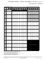
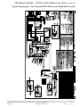
Performance Data – TR H/V 009
325 CFM Nominal (Rated) Airflow
EWT
GPM
°F
20
30
40
50
60
70
80
85
90
100
110
120
Performance capacities shown in thousands of Btuh
WPD
PSI
FT
Cooling - EAT 80/67°F
Airflow
CFM
TC
SC
Sens/Tot
Ratio
kW
Heating - EAT 70°F
HR
EER
Airflow
CFM
HC
kW
HE
LAT
COP
2.3
4.5
10.5
395250
6.5
0.73
4.2
94.2
2.6
Operation not recommended
2.3
4.5
10.5
525330
6.7
0.66
4.4
88.8
3.0
1.1 1.33.0 25010.2 6.00.59
0.3911.626.6 2507.10.74 4.796.32.8
1.1 1.33.0 33010.7 6.80.64
0.4012.026.6 3307.30.67 5.090.43.2
1.7 1.94.4 25010.5 6.00.57
0.3611.729.5 2507.40.75 4.997.42.9
1.7 1.94.4 33010.9 6.80.62
0.3712.229.5 3307.60.67 5.391.23.3
2.3 3.58.1 25010.6 6.00.56
0.3411.831.1 2507.50.75 5.197.92.9
2.3 3.58.1 33011.0 6.80.61
0.3612.331.1 3307.70.68 5.491.73.4
1.1 0.92.0 2509.9 6.00.61
0.4311.322.8 2508.00.76 5.599.83.1
1.1 0.92.0 33010.3 6.80.66
0.4511.822.8 3308.20.69 5.993.13.5
1.7 1.53.5 25010.16.00.59
0.4011.5
25.4 250
8.40.775.8101.13.2
1.7 1.53.5 33010.5 6.80.64
0.4112.025.4 3308.60.69 6.294.13.6
2.3 3.06.8 25010.36.00.59
0.3811.6
26.8 250
8.60.786.0101.83.2
2.3 3.06.8 33010.7 6.80.64
0.4012.026.9 3308.80.70 6.494.73.7
1.1
0.6
1.5
250
9.4
6.0
0.63
0.48
11.1
19.5
250
9.0
0.79
6.4
103.3
3.4
1.1 0.61.5 3309.8 6.70.69
0.5011.619.5 3309.20.71 6.895.83.8
1.7
1.3
2.9
250
9.7
6.0
0.62
0.45
11.3
21.7
250
9.4
0.80
6.7
104.8
3.5
1.7 1.32.9 33010.1 6.80.67
0.4711.721.7 3309.60.72 7.297.03.9
2.3
2.6
6.0
250
9.9
6.0
0.61
0.43
11.3
23.0
250
9.6
0.80
6.9
105.6
3.5
2.3 2.66.0 33010.3 6.80.66
0.4511.823.0 3309.80.72 7.497.64.0
1.1 0.51.2 250 9.0 5.9 0.650.5410.816.5 2509.9 0.81 7.2106.83.6
1.1 0.51.2 3309.4 6.70.71
0.5711.316.5 330
10.20.73 7.798.54.1
1.7
1.1
2.5
250
9.3
5.9
0.64
0.50
11.0
18.5
250
10.4
0.82
7.6
108.4
3.7
1.7 1.12.5 3309.7 6.70.69
0.5211.518.5 330
10.60.74 8.199.84.2
2.3
2.3
5.4
250
9.5
6.0
0.63
0.48
11.1
19.6
250
10.6
0.83
7.8
109.3
3.7
2.3
2.3
5.4
330
9.8
6.7
0.69
0.50
11.6
19.6
330
10.9
0.75
8.3
100.5
4.3
1.1 0.4 0.9 250 8.5 5.8 0.680.61 10.614.0 25010.80.84 8.0 110.1 3.8
1.1 0.4 0.9 330 8.8 6.5 0.740.63 11.014.0 33011.10.75 8.5 101.1 4.3
1.7
1.0
2.3
250
8.8
5.8
0.66
0.56
10.7
15.6
250
11.3
0.85
8.4
111.9
3.9
1.7 1.0 2.3 330 9.2 6.6 0.720.59 11.215.6 33011.60.77 9.0 102.5 4.4
2.3
2.1
4.9
250
9.1
5.9
0.65
0.53
10.9
17.1
250
11.4
0.85
8.5
112.1
3.9
2.3 2.1 4.9 330 9.5 6.7 0.710.55 11.317.1 33011.60.77 9.0 102.7 4.4
1.1 0.3 0.8 250 8.0 5.6 0.700.67 10.311.8 25011.70.87 8.7 113.3 4.0
1.1 0.30.8 330 8.3 6.3 0.770.7010.711.8 33012.00.78 9.3103.64.5
1.7 0.9 2.1 250 8.3 5.7 0.690.63 10.513.2 25012.20.88 9.1 115.1 4.0
1.7 0.9 2.1 330 8.6 6.5 0.750.66 10.913.2 33012.50.79 9.8 105.0 4.6
2.3 2.0 4.6 250 8.6 5.8 0.670.59 10.614.4 25012.20.88 9.2 115.4 4.1
2.3
2.0
4.6
330
8.9
6.5
0.73
0.62
11.1
14.4
330
12.5
0.79
9.8
105.2
4.6
1.1 0.30.7 2507.7 5.50.710.710.111.0 250
12.00.88 9.0114.54.0
1.1 0.30.7 330 8.0 6.2 0.780.7310.511.0 33012.3 0.8 9.6104.64.6
1.70.9
2.02508.05.60.70
0.67
10.3
12.1250
12.6
0.99.5
116.5
4.1
1.7
0.9
2.0
330
8.4
6.4
0.76
0.69
10.7
12.1
330
12.9
0.8
10.1
106.1
4.7
2.31.9
4.42508.35.70.69
0.63
10.5
13.3250
12.6
0.99.5
116.8
4.1
2.3
1.9
4.4
330
8.7
6.5
0.75
0.65
10.9
13.3
330
12.9
0.8
10.2
106.3
4.7
1.1 0.3 0.6 250 7.5 5.4 0.720.73 10.010.2 25012.30.89 9.3 115.7 4.1
1.1 0.3 0.6 330 7.8 6.2 0.790.76 10.410.2 33012.60.80 9.9 105.5 4.6
1.7
0.8
1.9
250
7.7
5.5
0.71
0.70
10.1
11.1
250
12.9
0.91
9.8
117.9
4.2
1.7
0.8
1.9
330
8.1
6.3
0.78
0.73
10.6
11.1
330
13.3
0.82
10.5
107.2
4.8
2.3 1.8 4.3 250 8.0 5.6 0.700.66 10.312.1 25013.00.91 9.9 118.2 4.2
2.3 1.8 4.3 330 8.4 6.4 0.760.69 10.712.1 33013.30.82 10.5107.4 4.8
1.1 0.20.6 2506.8 5.10.76
0.829.6 8.2 395
1.1
0.2
0.6
330
7.0
5.8
0.82
0.86
10.0
8.2
525
1.7 0.81.7 2507.1 5.30.74
0.789.8 9.2 395
1.7
0.8
1.7
330
7.4
6.0
0.81
0.81
10.2
9.2
525
2.3 1.74.0 2507.3 5.40.73
0.759.9 9.7 395
2.3
1.7
4.0
330
7.6
6.1
0.80
0.78
10.3
9.7
525
1.1 0.20.5 2506.1 4.80.79
0.909.2 6.8 395
1.1 0.20.5 3306.3 5.40.85
0.949.5 6.8 525
1.7 0.71.6 2506.5 5.00.77
0.869.4 7.6 395
Operation not recommended
1.7 0.71.6 3306.8 5.60.84
0.899.8 7.6 525
2.3 1.63.8 2506.7 5.10.76
0.839.5 8.0 395
2.3 1.63.8 3307.0 5.80.83
0.879.9 8.0 525
1.1 0.20.4 2505.4 4.40.82
0.988.7 5.5 395
1.1 0.20.4 3305.6 5.00.89
1.029.1 5.5 525
1.7 0.71.6 2505.8 4.60.80
0.949.0 6.2 395
1.7 0.71.6 3306.0 5.20.87
0.989.4 6.2 525
2.3 1.63.6 2506.0 4.70.79
0.919.1 6.5 395
2.3 1.63.6 3306.2 5.40.86
0.959.5 6.5 525
Interpolation is permissible; extrapolation is not.
All entering air conditions are 80°F DB and 67°F WB in cooling, and 70°F DB in heating.
AHRI/ISO certified conditions are 80.6°F DB and 66.2°F WB in cooling and 68°F DB in heating.
Table does not reflect fan or pump power corrections for AHRI/ISO conditions.
All performance is based upon the lower voltage of dual voltage rated units.
Performance stated is at the rated power supply; performance may vary as the power supply varies from the rated.
Operation below 40°F EWT is based upon a 15% methanol antifreeze solution.
Operation below 60°F EWT requires optional insulated water/refrigerant circuit.
See performance correction tables for operating conditions other than those listed above.
See Performance Data Selection Notes for operation in the shaded areas.
ClimateMaster works continually to improve its products. As a result, the design and specifications of each product at the time of order may be changed without notice and may not be as described herein. Please contact ClimateMaster's Customer
Service Department at 1-405-745-6000 for specific information on the current design and specifications. Statements and other information contained herein are not express warranties and do not form the basis of any bargain between the parties,
but are merely ClimateMaster's opinion or commendation of its products. The latest version of this document is available at climatemaster.com.
LC516 - 11
Revised: 18 July, 2013
Page ______ of ______
TR Series 60Hz - HFC-410A Submittal Data
Eng/I-P
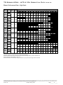
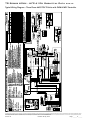
Performance Data – TR H/V 012
400 CFM Nominal (Rated) Airflow
EWT
GPM
°F
20
30
40
50
60
70
80
85
90
100
110
120
Performance capacities shown in thousands of Btuh
WPD
PSI
FT
Cooling - EAT 80/67°F
Airflow
CFM
TC
SC
Sens/Tot
Ratio
kW
Heating - EAT 70°F
HR
EER
Airflow
CFM
HC
kW
HE
LAT
COP
3.0
8.5
19.6
300300
8.5
0.98
5.3
96.2
2.5
Operation not recommended
3.0
8.5
19.6
400400
8.7
0.88
5.7
90.2
2.9
1.5 1.94.3 30014.2 8.20.58
0.5516.125.8 3009.31.00 6.098.62.7
1.5 1.94.3 40014.8 9.30.63
0.5716.825.8 4009.50.90 6.491.93.1
2.3 3.68.4 30014.3 8.20.58
0.5116.127.9 3009.61.01 6.399.72.8
2.3 3.68.4 40014.9 9.30.63
0.5316.727.9 4009.90.91 6.892.83.2
3.0 6.715.5 30014.3 8.2 0.580.5016.028.8 3009.8 1.02 6.5100.42.8
3.0 6.715.5 400 14.9 9.3 0.630.52 16.628.8 40010.10.92 7.0 93.3 3.2
1.5 1.4 3.2 300 14.0 8.1 0.580.61 16.022.9 30010.61.04 7.1 102.6 3.0
1.5 1.4 3.2 400 14.5 9.2 0.630.63 16.722.9 40010.80.93 7.6 95.0 3.4
2.3 3.06.9 30014.2 8.2 0.580.5716.125.1 30011.01.05 7.6104.13.1
2.3 3.06.9 40014.8 9.30.63
0.5916.825.1 400
11.30.94 8.196.23.5
3.0 5.713.1 30014.3 8.2 0.580.5416.126.2 30011.31.06 7.8104.93.1
3.0 5.713.140014.8 9.30.63
0.5716.826.2 400
11.60.95 8.396.83.6
1.5 1.12.5 30013.5 7.9 0.580.6715.820.1 30011.91.08 8.3106.83.2
1.5 1.1 2.5 400 14.1 8.9 0.630.70 16.520.1 40012.20.97 8.9 98.2 3.7
2.3 2.6 6.0 300 13.9 8.0 0.580.62 16.022.2 30012.51.09 8.9 108.6 3.4
2.3 2.6 6.0 400 14.4 9.1 0.630.65 16.722.2 40012.80.98 9.5 99.6 3.8
3.0 5.011.5 300 14.0 8.1 0.580.60 16.123.3 30012.81.10 9.1 109.6 3.4
3.0 5.011.5 400 14.6 9.2 0.630.63 16.723.3 40013.10.99 9.8 100.4 3.9
1.5
0.9
2.1
300
12.9
7.6
0.59
0.74
15.5
17.4
300
13.3
1.11
9.6
111.1
3.5
1.5 0.9 2.1 400 13.5 8.6 0.640.77 16.117.4 40013.61.00 10.2101.5 4.0
2.3 2.3 5.3 300 13.4 7.8 0.580.69 15.719.3 30014.01.13 10.2113.1 3.6
2.3 2.3 5.3 400 13.9 8.8 0.630.72 16.419.3 40014.31.02 10.8103.1 4.1
3.0 4.510.3 300 13.6 7.9 0.580.67 15.820.4 30014.31.14 10.5114.2 3.7
3.0 4.510.3 400 14.1 8.9 0.630.69 16.520.4 40014.71.03 11.2104.0 4.2
1.5 0.8 1.8 300 12.2 7.3 0.600.82 15.014.9 30014.71.15 10.8115.3 3.7
1.5 0.8 1.8 400 12.7 8.3 0.650.85 15.614.9 40015.01.04 11.5104.8 4.2
2.3 2.1 4.8 300 12.5 7.4 0.590.77 15.216.3 30015.41.18 11.4117.6 3.8
2.3 2.1 4.8 400 13.1 8.4 0.640.80 15.816.3 40015.81.06 12.2106.5 4.4
3.0 4.1 9.5 300 12.7 7.5 0.590.75 15.317.0 30015.81.19 11.7118.8 3.9
3.0 4.1 9.5 400 13.3 8.5 0.640.78 15.917.0 40016.21.07 12.5107.5 4.4
1.5 0.7 1.5 300 11.4 7.0 0.610.90 14.512.7 30016.01.20 11.9119.4 3.9
1.5 0.7 1.5 400 11.9 7.9 0.670.94 15.112.7 40016.41.08 12.7108.0 4.5
2.3 1.9 4.4 300 11.8 7.1 0.600.85 14.713.9 30016.81.22 12.6121.7 4.0
2.3 1.9 4.4 400 12.3 8.0 0.650.88 15.313.9 40017.21.10 13.4109.8 4.6
3.0 3.8 8.8 300 12.0 7.2 0.600.83 14.814.5 30017.21.24 12.9123.0 4.1
3.0
3.8
8.8
400
12.5
8.1
0.65
0.86
15.4
14.5
400
17.6
1.11
13.8
110.7
4.6
1.5 0.61.5 30010.9 6.80.620.914.211.7 300
16.61.2212.5
121.34.0
1.5
0.6
1.5
400
11.4
7.7
0.68
0.98
14.7
11.7
400
17.0
1.1
13.3
109.4
4.6
2.3
1.8
4.2
300
11.4
6.9
0.61
0.89
14.4
12.8
300
17.4
1.3
13.1
123.6
4.1
2.3
1.8
4.2
400
11.9
7.9
0.66
0.93
15.0
12.8
400
17.8
1.1
14.0
111.2
4.6
3.0
3.7
8.5
300
11.6
7.0
0.60
0.87
14.5
13.4
300
17.7
1.3
13.4
124.8
4.1
3.0 3.78.5 40012.17.90.66
0.9015.1
13.4 400
18.21.114.3
112.14.7
1.5 0.6 1.4 300 10.5 6.7 0.630.99 13.910.7 30017.31.24 13.0123.3 4.1
1.5 0.6 1.4 400 10.9 7.5 0.691.03 14.410.7 40017.71.12 13.9110.9 4.6
2.3
1.8
4.1
300
11.0
6.8
0.62
0.93
14.1
11.7
300
18.0
1.28
13.6
125.5
4.1
2.3
1.8
4.1
400
11.4
7.7
0.67
0.97
14.7
11.7
400
18.4
1.15
14.5
112.6
4.7
3.0 3.6 8.2 300 11.2 6.8 0.610.91 14.312.3 30018.31.29 13.9126.6 4.2
3.0 3.6 8.2 400 11.6 7.7 0.670.95 14.812.3 40018.81.16 14.8113.5 4.7
1.5
0.5
1.2
300
9.5
6.4
0.67
1.07
13.2
8.9
300
1.5
0.5
1.2
400
9.9
7.2
0.72
1.12
13.8
8.9
400
2.3
1.7
3.8
300
10.1
6.5
0.65
1.02
13.5
9.8
300
2.3
1.7
3.8
400
10.5
7.3
0.70
1.06
14.1
9.8
400
3.0
3.3
7.7
300
10.4
6.6
0.64
1.00
13.8
10.4
300
3.0
3.3
7.7
400
10.8
7.5
0.69
1.04
14.3
10.4
400
1.5
0.5
1.1
300
8.5
6.0
0.71
1.17
12.5
7.3
300
1.5
0.5
1.1
400
8.9
6.8
0.77
1.22
13.1
7.3
400
2.3
1.6
3.6
300
9.1
6.2
0.68
1.12
12.9
8.1
300
Operation not recommended
2.3
1.6
3.6
400
9.4
7.0
0.74
1.16
13.4
8.1
400
3.0
3.2
7.3
300
9.4
6.3
0.67
1.09
13.1
8.6
300
3.0
3.2
7.3
400
9.8
7.1
0.73
1.14
13.7
8.6
400
1.5
0.4
1.0
300
7.5
5.7
0.76
1.27
11.8
5.9
300
1.5
0.4
1.0
400
7.8
6.4
0.82
1.32
12.3
5.9
400
2.3
1.5
3.4
300
8.0
5.8
0.73
1.22
12.2
6.6
300
2.3
1.5
3.4
400
8.3
6.6
0.79
1.27
12.7
6.6
400
3.0
3.0
7.0
300
8.3
5.9
0.71
1.19
12.4
7.0
300
3.0
3.0
7.0
400
8.7
6.7
0.77
1.24
12.9
7.0
400
Interpolation is permissible; extrapolation is not.
All entering air conditions are 80°F DB and 67°F WB in cooling, and 70°F DB in heating.
AHRI/ISO certified conditions are 80.6°F DB and 66.2°F WB in cooling and 68°F DB in heating.
Table does not reflect fan or pump power corrections for AHRI/ISO conditions.
All performance is based upon the lower voltage of dual voltage rated units.
Performance stated is at the rated power supply; performance may vary as the power supply varies from the rated.
Operation below 40°F EWT is based upon a 15% methanol antifreeze solution.
Operation below 60°F EWT requires optional insulated water/refrigerant circuit.
See performance correction tables for operating conditions other than those listed above.
See Performance Data Selection Notes for operation in the shaded areas.
ClimateMaster works continually to improve its products. As a result, the design and specifications of each product at the time of order may be changed without notice and may not be as described herein. Please contact ClimateMaster's Customer
Service Department at 1-405-745-6000 for specific information on the current design and specifications. Statements and other information contained herein are not express warranties and do not form the basis of any bargain between the parties,
but are merely ClimateMaster's opinion or commendation of its products. The latest version of this document is available at climatemaster.com.
LC516 - 12
Revised: 18 July, 2013
Page ______ of ______
TR Series 60Hz - HFC-410A Submittal Data
Eng/I-P
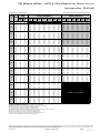
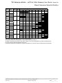
Performance Data – TR H/V 015
525 CFM Nominal (Rated) Airflow
EWT
GPM
°F
20
30
40
50
60
70
80
85
90
100
110
120
Performance capacities shown in thousands of Btuh
WPD
PSI
FT
Cooling - EAT 80/67°F
Airflow
CFM
TC
SC
Sens/Tot
Ratio
kW
Heating - EAT 70°F
HR
EER
Airflow
CFM
HC
kW
HE
LAT
COP
3.8
4.1
9.5
395
395
9.5
1.07
6.1
92
2.62
Operation not recommended
3.8
4.1
9.5
525
525
9.8
0.96
6.5
87
2.98
1.9 1.0 2.3 395 17.3 10.8 0.62 0.61 19.428.4 395 10.61.09 7.1 95 2.84
1.9 1.0 2.3 525 18.1 12.2 0.67 0.64 20.228.4 525 10.90.98 7.5 89 3.24
2.8 1.8 4.3 395 17.5 10.8 0.62 0.56 19.431.1 395 11.11.11 7.5 96 2.94
2.8 1.8 4.3 525 18.2 12.2 0.67 0.59 20.231.1 525 11.40.99 8.0 90 3.35
3.8 3.3 7.7 395 17.5 10.8 0.62 0.54 19.432.2 395 11.31.11 7.7 97 2.99
3.8 3.3 7.7 525 18.3 12.2 0.67 0.57 20.232.2 525 11.61.00 8.2 90 3.41
1.9 0.8 1.8 395 17.0 10.6 0.63 0.68 19.324.8 395 12.31.13 8.5 99 3.18
1.9 0.8 1.8 525 17.7 12.0 0.68 0.71 20.124.8 525 12.61.02 9.1 92 3.62
2.8 1.6 3.6 395 17.2 10.7 0.62 0.63 19.427.3 395 12.81.14 9.0 100 3.29
2.8 1.6 3.6 525 18.0 12.1 0.68 0.66 20.227.3 525 13.11.03 9.7 93 3.75
3.8 2.9 6.6 395 17.4 10.8 0.62 0.60 19.428.8 395 13.11.15 9.3 101 3.35
3.8 2.9 6.6 525 18.1 12.2 0.67 0.63 20.228.8 525 13.51.03 10.0 94 3.82
1.9 0.6 1.5 395 16.4 10.4 0.63 0.76 19.021.6 395 13.91.16 10.0 103 3.50
1.9 0.6 1.5 525 17.1 11.8 0.69 0.79 19.821.6 525 14.21.05 10.7 95 3.99
2.8 1.4 3.1 395 16.8 10.6 0.63 0.71 19.223.8 395 14.61.18 10.6 104 3.63
2.8 1.4 3.1 525 17.5 12.0 0.68 0.74 20.023.8 525 14.91.06 11.3 96 4.13
3.8 2.5 5.8 395 17.0 10.6 0.63 0.68 19.325.0 395 14.91.18 10.9 105 3.69
3.8 2.5 5.8 525 17.7 12.0 0.68 0.71 20.125.0 525 15.31.06 11.7 97 4.21
1.9 0.6 1.3 395 15.7 10.2 0.65 0.84 18.618.7 395 15.51.20 11.5 106 3.81
1.9 0.6 1.3 525 16.4 11.5 0.70 0.88 19.418.7 525 15.91.07 12.2 98 4.34
2.8 1.2 2.8 395 16.2 10.4 0.64 0.79 18.920.5 395 16.31.21 12.1 108 3.94
2.8 1.2 2.8 525 16.9 11.7 0.69 0.82 19.720.5 525 16.71.09 13.0 99 4.50
3.8 2.3 5.3 395 16.4 10.4 0.63 0.76 19.021.6 395 16.71.22 12.5 109 4.02
3.8 2.3 5.3 525 17.1 11.8 0.69 0.79 19.821.6 525 17.11.09 13.3 100 4.58
1.9 0.5 1.1 395 15.2 10.1 0.66 0.93 18.316.2 395 17.11.22 12.9 110 4.10
1.9 0.5 1.1 525 15.8 11.4 0.72 0.97 19.116.3 525 17.51.10 13.8 101 4.68
2.8 1.1 2.5 395 15.5 10.1 0.65 0.88 18.517.6 395 18.01.24 13.7 112 4.25
2.8 1.1 2.5 525 16.1 11.4 0.71 0.91 19.217.6 525 18.41.11 14.6 102 4.85
3.8 2.1 4.9 395 15.8 10.2 0.65 0.85 18.618.6 395 18.41.25 14.1 113 4.33
3.8 2.1 4.9 525 16.4 11.5 0.70 0.88 19.418.6 525 18.81.12 15.0 103 4.94
1.9 0.4 1.0 395 14.3 9.8 0.68 1.03 17.813.9 395 18.71.25 14.3 114 4.38
1.9 0.4 1.0 525 14.9 11.1 0.74 1.07 18.513.9 525 19.21.12 15.3 104 5.00
2.8 1.0 2.4 395 14.7 9.8 0.67 0.97 18.015.1 395 19.61.27 15.1 116 4.54
2.8 1.0 2.4 525 15.3 11.1 0.73 1.01 18.715.1 525 20.11.14 16.2 105 5.18
3.8 2.0 4.6 395 14.9 9.9 0.66 0.94 18.215.9 395 20.11.27 15.6 117 4.62
3.8 2.0 4.6 525 15.6 11.2 0.72 0.98 18.915.9 525 20.61.14 16.6 106 5.27
1.9 0.4 0.9 395 13.8 9.6 0.70 1.1 17.512.8 395 19.51.26 15.0 116 4.52
1.9 0.4 0.9 525 14.4 10.9 0.76 1.13 18.212.8 525 19.91.13 16.0 105 5.15
2.8 1.0 2.3 395 14.2 9.7 0.68 1.02 17.713.9 395 20.41.28 15.9 118 4.68
2.8 1.0 2.3 525 14.8 11.0 0.74 1.07 18.413.9 525 20.91.15 16.9 107 5.34
3.8 1.9 4.4 395 14.5 9.8 0.67 0.99 17.914.7 395 20.91.29 16.3 119 4.77
3.8 1.9 4.4 525 15.1 11.1 0.73 1.03 18.614.7 525 21.41.15 17.4 108 5.43
1.9 0.4 0.9 395 13.3 9.5 0.71 1.14 17.211.7 395 20.21.28 15.7 117 4.65
1.9 0.4 0.9 525 13.9 10.7 0.77 1.19 18.011.7 525 20.71.15 16.8 107 5.30
2.8 1.0 2.2 395 13.7 9.5 0.69 1.08 17.412.8 395 21.21.29 16.6 120 4.82
2.8 1.0 2.2 525 14.3 10.8 0.75 1.12 18.112.8 525 21.71.16 17.7 108 5.49
3.8 1.9 4.3 395 14.1 9.6 0.69 1.04 17.613.5 395 21.71.30 17.1 121 4.90
3.8 1.9 4.3 525 14.6 10.9 0.74 1.08 18.313.5 525 22.21.17 18.2 109 5.59
1.90.40.8395
12.49.20.741.25
16.69.9395
1.90.40.8525
12.910.40.801.31
17.39.9525
2.8
0.9
2.1
395
12.8
9.2
0.72
1.19
16.8
10.8
395
2.8
0.9
2.1
525
13.3
10.4
0.78
1.23
17.5
10.8
525
3.8
1.8
4.1
395
13.1
9.3
0.71
1.15
17.0
11.4
395
3.8
1.8
4.1
525
13.6
10.5
0.77
1.20
17.7
11.4
525
1.90.30.7395
11.38.80.781.37
16.08.3395
1.90.30.7525
11.810.00.841.43
16.78.3525
2.80.81.9395
11.88.90.751.30
16.29.0395
Operation not recommended
2.80.81.9525
12.210.00.821.36
16.99.0525
3.81.73.9395
12.19.00.741.27
16.49.5395
3.81.73.9525
12.610.20.811.32
17.19.5525
1.90.30.7395
10.38.50.821.50
15.56.9395
1.90.30.7525
10.89.60.891.56
16.16.9525
2.80.81.8395
10.78.50.791.43
15.67.5395
2.80.81.8525
11.29.60.861.48
16.27.5525
3.81.63.7395
11.08.60.781.39
15.87.9395
3.81.63.7525
11.59.80.851.45
16.47.9525
Interpolation is permissible; extrapolation is not.
All entering air conditions are 80°F DB and 67°F WB in cooling, and 70°F DB in heating.
AHRI/ISO certified conditions are 80.6°F DB and 66.2°F WB in cooling and 68°F DB in heating.
Table does not reflect fan or pump power corrections for AHRI/ISO conditions.
All performance is based upon the lower voltage of dual voltage rated units.
Performance stated is at the rated power supply; performance may vary as the power supply varies from the rated.
Operation below 40°F EWT is based upon a 15% methanol antifreeze solution.
Operation below 60°F EWT requires optional insulated water/refrigerant circuit.
See performance correction tables for operating conditions other than those listed above.
See Performance Data Selection Notes for operation in the shaded areas.
ClimateMaster works continually to improve its products. As a result, the design and specifications of each product at the time of order may be changed without notice and may not be as described herein. Please contact ClimateMaster's Customer
Service Department at 1-405-745-6000 for specific information on the current design and specifications. Statements and other information contained herein are not express warranties and do not form the basis of any bargain between the parties,
but are merely ClimateMaster's opinion or commendation of its products. The latest version of this document is available at climatemaster.com.
LC516 - 13
Revised: 18 July, 2013
Page ______ of ______
TR Series 60Hz - HFC-410A Submittal Data
Eng/I-P
Performance Data – TR H/V 018
600 CFM Nominal (Rated) Airflow
EWT
GPM
°F
20
30
40
50
60
70
80
85
90
100
110
120
4.5
4.5
2.3
2.3
3.4
3.4
4.5
4.5
2.3
2.3
3.4
3.4
4.5
4.5
2.3
2.3
3.4
3.4
4.5
4.5
2.3
2.3
3.4
3.4
4.5
4.5
2.3
2.3
3.4
3.4
4.5
4.5
2.3
2.3
3.4
3.4
4.5
4.5
2.3
2.3
3.4
3.4
4.5
4.5
2.3
2.3
3.4
3.4
4.5
4.5
2.3
2.3
3.4
3.4
4.5
4.5
2.3
2.3
3.4
3.4
4.5
4.5
2.3
2.3
3.4
3.4
4.5
4.5
Performance capacities shown in thousands of Btuh
WPD
PSI
FT
7.2
7.2
2.1
2.1
3.4
3.4
5.9
5.9
1.7
1.7
2.9
2.9
5.1
5.1
1.4
1.4
2.6
2.6
4.6
4.6
1.3
1.3
2.3
2.3
4.2
4.2
1.1
1.1
2.1
2.1
3.9
3.9
1.0
1.0
2.0
2.0
3.6
3.6
1.0
1.0
1.9
1.9
3.5
3.5
0.9
0.9
1.8
1.8
3.4
3.4
0.9
0.9
1.7
1.7
3.2
3.2
0.8
0.8
1.6
1.6
3.1
3.1
0.7
0.7
1.6
1.6
2.9
2.9
16.7
16.7
4.9
4.9
7.9
7.9
13.7
13.7
3.9
3.9
6.7
6.7
11.8
11.8
3.3
3.3
5.9
5.9
10.6
10.6
2.9
2.9
5.3
5.3
9.6
9.6
2.6
2.6
4.9
4.9
8.9
8.9
2.3
2.3
4.5
4.5
8.3
8.3
2.2
2.2
4.4
4.4
8.1
8.1
2.1
2.1
4.2
4.2
7.9
7.9
2.0
2.0
4.0
4.0
7.4
7.4
1.8
1.8
3.8
3.8
7.1
7.1
1.7
1.7
3.6
3.6
6.8
6.8
Cooling - EAT 80/67°F
Airflow
CFM
TC
SC
Sens/Tot
Ratio
kW
Heating - EAT 70°F
HR
EER
450
Operation not recommended
600
450
22.1
14.2
0.64
0.72
24.5
30.7
600
23.0
16.1
0.70
0.75
25.5
30.8
450
22.9
14.4
0.63
0.64
25.1
35.8
600
23.9
16.3
0.68
0.67
26.1
35.8
450
23.3
14.4
0.62
0.60
25.3
39.0
600
24.3
16.3
0.67
0.62
26.4
39.0
450
21.1
13.9
0.66
0.82
23.9
25.6
600
22.0
15.7
0.72
0.86
24.9
25.6
450
21.9
14.2
0.65
0.75
24.4
29.3
600
22.8
16.0
0.70
0.78
25.4
29.3
450
22.5
14.5
0.64
0.71
24.9
31.9
600
23.5
16.4
0.70
0.74
25.9
31.9
450
20.4
13.7
0.67
0.93
23.5
21.9
600
21.2
15.5
0.73
0.97
24.5
22.0
450
20.8
13.8
0.66
0.85
23.7
24.4
600
21.7
15.6
0.72
0.89
24.7
24.4
450
21.2
13.9
0.66
0.81
23.9
26.1
600
22.1
15.8
0.72
0.85
24.9
26.1
450
19.3
13.2
0.68
1.04
22.8
18.6
600
20.1
14.9
0.74
1.08
23.8
18.6
450
19.8
13.4
0.68
0.96
23.0
20.6
600
20.6
15.1
0.73
1.00
24.0
20.6
450
20.1
13.5
0.67
0.92
23.3
21.9
600
21.0
15.3
0.73
0.96
24.2
21.9
450
18.2
12.7
0.69
1.15
22.1
15.8
600
19.0
14.3
0.76
1.20
23.1
15.8
450
18.7
12.8
0.69
1.07
22.3
17.4
600
19.4
14.5
0.75
1.12
23.2
17.4
450
19.1
13.0
0.68
1.03
22.6
18.4
600
19.8
14.7
0.74
1.08
23.5
18.4
450
17.0
12.1
0.71
1.28
21.4
13.3
600
17.7
13.7
0.77
1.33
22.3
13.3
450
17.5
12.3
0.70
1.20
21.6
14.7
600
18.3
13.9
0.76
1.25
22.5
14.7
450
17.9
12.5
0.69
1.15
21.9
15.5
600
18.7
14.1
0.76
1.20
22.8
15.5
450
16.4
11.8
0.72
1.35
21.0
12.2
600
17.1
13.3
0.78
1.40
21.9
12.2
450
16.9
12.0
0.71
1.26
21.2
13.5
600
17.6
13.5
0.77
1.31
22.1
13.5
450
17.3
12.2
0.70
1.22
21.5
14.3
600
18.0
13.8
0.76
1.27
22.4
14.3
450
15.8
11.5
0.73
1.42
20.6
11.1
600
16.4
13.0
0.79
1.48
21.5
11.1
450
16.3
11.7
0.71
1.33
20.8
12.3
600
17.0
13.2
0.78
1.38
21.7
12.3
450
16.7
11.9
0.71
1.28
21.1
13.0
600
17.4
13.4
0.77
1.34
22.0
13.0
450
14.4
10.8
0.75
1.57
19.8
9.2
600
15.0
12.2
0.82
1.63
20.6
9.2
450
15.0
11.0
0.74
1.48
20.0
10.1
600
15.6
12.5
0.80
1.54
20.8
10.1
450
15.4
11.2
0.73
1.43
20.3
10.8
600
16.0
12.7
0.79
1.49
21.1
10.8
450
12.9
10.1
0.78
1.74
18.8
7.4
600
13.4
11.4
0.85
1.81
19.6
7.4
450
13.5
10.3
0.76
1.64
19.1
8.2
600
14.0
11.6
0.83
1.71
19.9
8.2
450
13.9
10.5
0.75
1.59
19.4
8.8
600
14.5
11.9
0.82
1.65
20.2
8.8
450
11.2
9.2
0.82
1.92
17.8
5.8
600
11.6
10.4
0.89
2.00
18.5
5.8
450
11.8
9.5
0.80
1.82
18.1
6.5
600
12.3
10.7
0.87
1.89
18.8
6.5
450
12.3
9.7
0.79
1.77
18.4
7.0
600
12.8
11.0
0.86
1.84
19.1
7.0
Airflow
CFM
HC
kW
HE
LAT
450
11.2
1.25
7.2
93
600
11.4
1.13
7.6
88
450
12.4
1.29
8.2
96
600
12.7
1.16
8.8
90
450
12.9
1.30
8.7
97
600
13.3
1.17
9.3
90
450
13.2
1.31
9.0
97
600
13.5
1.17
9.6
91
450
14.3
1.33
9.9
99
600
14.7
1.20
10.6
93
450
15.0
1.35
10.5
101
600
15.3
1.21
11.2
94
450
15.3
1.35
10.8
102
600
15.7
1.22
11.6
94
450
16.3
1.37
11.7
103
600
16.6
1.23
12.5
96
450
17.0
1.39
12.4
105
600
17.4
1.25
13.2
97
450
17.4
1.39
12.7
106
600
17.9
1.25
13.6
98
450
18.2
1.41
13.4
107
600
18.6
1.26
14.3
99
450
19.1
1.42
14.2
109
600
19.6
1.28
15.2
100
450
19.6
1.43
14.7
110
600
20.1
1.29
15.7
101
450
20.2
1.44
15.2
112
600
20.7
1.29
16.2
102
450
21.2
1.46
16.1
114
600
21.7
1.31
17.2
103
450
21.7
1.46
16.6
115
600
22.3
1.32
17.8
104
450
22.1
1.47
17.0
116
600
22.7
1.32
18.2
105
450
23.3
1.49
18.0
118
600
23.9
1.34
19.3
107
450
23.9
1.50
18.6
119
600
24.5
1.35
19.9
108
450
23.1
1.49
17.9
118
600
23.7
1.33
19.1
107
450
24.3
1.50
19.0
120
600
24.9
1.35
20.3
108
450
25.0
1.51
19.6
121
600
25.6
1.36
20.9
110
450
24.1
1.50
18.8
120
600
24.7
1.35
20.1
108
450
25.4
1.52
20.0
122
600
26.0
1.37
21.3
110
450
26.1
1.53
20.6
124
600
26.7
1.38
22.0
111
450
600
450
600
450
600
450
600
450
Operation not recommended
600
450
600
450
600
450
600
450
600
COP
2.61
2.98
2.83
3.22
2.92
3.33
2.97
3.38
3.15
3.59
3.26
3.72
3.32
3.78
3.47
3.96
3.60
4.10
3.67
4.18
3.79
4.32
3.93
4.49
4.01
4.58
4.11
4.68
4.27
4.86
4.35
4.96
4.41
5.03
4.59
5.23
4.68
5.34
4.56
5.20
4.74
5.41
4.84
5.51
4.71
5.37
4.89
5.58
4.99
5.69
Interpolation is permissible; extrapolation is not.
All entering air conditions are 80°F DB and 67°F WB in cooling, and 70°F DB in heating.
AHRI/ISO certified conditions are 80.6°F DB and 66.2°F WB in cooling and 68°F DB in heating.
Table does not reflect fan or pump power corrections for AHRI/ISO conditions.
All performance is based upon the lower voltage of dual voltage rated units.
Performance stated is at the rated power supply; performance may vary as the power supply varies from the rated.
Operation below 40°F EWT is based upon a 15% methanol antifreeze solution.
Operation below 60°F EWT requires optional insulated water/refrigerant circuit.
See performance correction tables for operating conditions other than those listed above.
See Performance Data Selection Notes for operation in the shaded areas.
ClimateMaster works continually to improve its products. As a result, the design and specifications of each product at the time of order may be changed without notice and may not be as described herein. Please contact ClimateMaster's Customer
Service Department at 1-405-745-6000 for specific information on the current design and specifications. Statements and other information contained herein are not express warranties and do not form the basis of any bargain between the parties,
but are merely ClimateMaster's opinion or commendation of its products. The latest version of this document is available at climatemaster.com.
LC516 - 14
Revised: 18 July, 2013
Page ______ of ______
TR Series 60Hz - HFC-410A Submittal Data
Eng/I-P
Performance Data – TR H/V 024
800 CFM Nominal (Rated) Airflow
EWT
GPM
°F
20
30
40
50
60
70
80
85
90
100
110
120
6.0
6.0
3.0
3.0
4.5
4.5
6.0
6.0
3.0
3.0
4.5
4.5
6.0
6.0
3.0
3.0
4.5
4.5
6.0
6.0
3.0
3.0
4.5
4.5
6.0
6.0
3.0
3.0
4.5
4.5
6.0
6.0
3.0
3.0
4.5
4.5
6.0
6.0
3.0
3.0
4.5
4.5
6.0
6.0
3.0
3.0
4.5
4.5
6.0
6.0
3.0
3.0
4.5
4.5
6.0
6.0
3.0
3.0
4.5
4.5
6.0
6.0
3.0
3.0
4.5
4.5
6.0
6.0
Performance capacities shown in thousands of Btuh
WPD
PSI
FT
8.5
8.5
2.2
2.2
4.0
4.0
7.2
7.2
1.9
1.9
3.6
3.6
6.4
6.4
1.7
1.7
3.2
3.2
5.9
5.9
1.5
1.5
3.0
3.0
5.5
5.5
1.4
1.4
2.8
2.8
5.2
5.2
1.3
1.3
2.6
2.6
4.9
4.9
1.3
1.3
2.6
2.6
4.8
4.8
1.2
1.2
2.5
2.5
4.7
4.7
1.2
1.2
2.4
2.4
4.5
4.5
1.1
1.1
2.3
2.3
4.3
4.3
1.0
1.0
2.2
2.2
4.2
4.2
19.6
19.6
5.2
5.2
9.3
9.3
16.7
16.7
4.4
4.4
8.2
8.2
14.9
14.9
3.9
3.9
7.4
7.4
13.6
13.6
3.5
3.5
6.9
6.9
12.6
12.6
3.2
3.2
6.4
6.4
11.9
11.9
3.0
3.0
6.1
6.1
11.3
11.3
2.9
2.9
5.9
5.9
11.0
11.0
2.8
2.8
5.8
5.8
10.7
10.7
2.7
2.7
5.5
5.5
10.3
10.3
2.5
2.5
5.3
5.3
9.9
9.9
2.4
2.4
5.1
5.1
9.6
9.6
Cooling - EAT 80/67°F
Airflow
CFM
TC
SC
Sens/Tot
Ratio
kW
Heating - EAT 70°F
HR
EER
640
Operation not recommended
850
640
27.7
17.4
0.63
1.12
31.5
24.8
850
28.9
19.7
0.68
1.16
32.8
24.8
640
28.2
17.5
0.62
1.05
31.8
26.9
850
29.4
19.8
0.67
1.09
33.1
26.9
640
28.5
17.5
0.62
1.02
31.9
28.0
850
29.6
19.8
0.67
1.06
33.2
28.0
640
26.9
17.1
0.64
1.23
31.1
21.9
850
28.0
19.4
0.69
1.28
32.4
21.9
640
27.5
17.3
0.63
1.15
31.4
24.0
850
28.7
19.6
0.68
1.19
32.7
24.0
640
27.8
17.4
0.63
1.11
31.5
25.1
850
28.9
19.7
0.68
1.16
32.8
25.1
640
26.2
16.9
0.65
1.36
30.8
19.3
850
27.3
19.1
0.70
1.42
32.1
19.3
640
26.7
17.0
0.64
1.26
31.0
21.1
850
27.8
19.3
0.69
1.32
32.2
21.1
640
27.0
17.1
0.64
1.22
31.1
22.1
850
28.1
19.4
0.69
1.27
32.4
22.1
640
25.3
16.6
0.66
1.52
30.4
16.7
850
26.3
18.8
0.71
1.58
31.7
16.7
640
25.7
16.7
0.65
1.40
30.5
18.3
850
26.8
18.9
0.70
1.46
31.7
18.3
640
26.1
16.8
0.64
1.35
30.6
19.3
850
27.1
19.0
0.70
1.41
31.9
19.3
640
24.1
16.2
0.67
1.70
29.9
14.2
850
25.1
18.3
0.73
1.77
31.1
14.2
640
24.6
16.3
0.66
1.57
30.0
15.7
850
25.6
18.4
0.72
1.63
31.2
15.7
640
25.0
16.4
0.66
1.51
30.1
16.6
850
26.0
18.6
0.71
1.57
31.4
16.6
640
22.9
15.7
0.69
1.91
29.4
12.0
850
23.8
17.8
0.75
1.99
30.6
12.0
640
23.4
15.8
0.67
1.76
29.4
13.3
850
24.4
17.9
0.73
1.84
30.7
13.3
640
23.8
16.0
0.67
1.70
29.6
14.1
850
24.8
18.1
0.73
1.77
30.8
14.1
640
22.2
15.5
0.70
2.03
29.2
11.0
850
23.1
17.5
0.76
2.12
30.4
11.0
640
22.8
15.6
0.68
1.88
29.2
12.2
850
23.7
17.6
0.74
1.95
30.4
12.2
640
23.2
15.7
0.68
1.80
29.3
12.9
850
24.1
17.8
0.74
1.88
30.5
12.9
640
21.6
15.3
0.71
2.16
28.9
10.0
850
22.4
17.3
0.77
2.25
30.1
10.0
640
22.2
15.4
0.69
1.99
29.0
11.1
850
23.1
17.4
0.75
2.07
30.1
11.1
640
22.5
15.4
0.69
1.91
29.0
11.8
850
23.4
17.5
0.75
1.99
30.2
11.8
640
20.2
14.8
0.74
2.44
28.5
8.3
850
21.0
16.8
0.80
2.54
29.7
8.3
640
20.8
14.9
0.72
2.25
28.5
9.2
850
21.6
16.9
0.78
2.34
29.7
9.2
640
21.1
15.0
0.71
2.16
28.5
9.8
850
22.0
17.0
0.77
2.25
29.7
9.8
640
18.8
14.4
0.77
2.77
28.3
6.8
850
19.5
16.3
0.84
2.88
29.4
6.8
640
19.3
14.4
0.75
2.55
28.1
7.6
850
20.1
16.3
0.81
2.66
29.2
7.6
640
19.7
14.5
0.74
2.45
28.1
8.0
850
20.5
16.4
0.80
2.55
29.3
8.0
640
17.1
13.9
0.81
3.13
27.9
5.5
850
17.8
15.7
0.88
3.26
29.0
5.5
640
17.8
14.0
0.78
2.89
27.8
6.2
850
18.6
15.8
0.85
3.01
28.9
6.2
640
18.3
14.1
0.77
2.78
27.9
6.6
850
19.1
16.0
0.84
2.89
29.0
6.6
Airflow
CFM
HC
kW
HE
LAT
640
15.5
1.91
9.5
92
850
15.9
1.71
10.1
87
640
17.2
1.93
11.0
95
850
17.6
1.74
11.8
89
640
18.0
1.95
11.7
96
850
18.4
1.75
12.5
90
640
18.4
1.95
12.1
97
850
18.8
1.76
12.9
91
640
19.9
1.98
13.4
99
850
20.4
1.78
14.4
92
640
20.8
2.00
14.3
100
850
21.3
1.79
15.3
93
640
21.3
2.01
14.7
101
850
21.9
1.80
15.7
94
640
22.6
2.03
15.9
103
850
23.2
1.82
17.0
95
640
23.7
2.05
16.9
104
850
24.3
1.84
18.0
96
640
24.3
2.06
17.4
105
850
24.9
1.85
18.6
97
640
25.3
2.08
18.3
107
850
25.9
1.87
19.6
98
640
26.6
2.10
19.4
108
850
27.2
1.89
20.7
100
640
27.2
2.12
20.0
109
850
27.9
1.90
21.4
100
640
27.9
2.13
20.7
110
850
28.6
1.91
22.1
101
640
29.2
2.16
21.8
112
850
29.9
1.94
23.3
103
640
29.9
2.17
22.5
113
850
30.6
1.95
24.0
103
640
30.4
2.18
22.9
114
850
31.1
1.96
24.4
104
640
31.7
2.21
24.0
116
850
32.5
1.99
25.7
105
640
32.4
2.23
24.6
117
850
33.1
2.00
26.3
106
640
31.5
2.21
23.8
116
850
32.3
1.98
25.5
105
640
32.7
2.24
25.0
117
850
33.5
2.01
26.7
107
640
33.4
2.25
25.5
118
850
34.2
2.02
27.2
107
640
32.6
2.23
24.8
117
850
33.4
2.01
26.5
106
640
33.8
2.26
25.9
119
850
34.6
2.03
27.6
108
640
34.4
2.28
26.4
120
850
35.2
2.05
28.2
108
640
850
640
850
640
850
640
850
640
Operation not recommended
850
640
850
640
850
640
850
640
850
COP
2.39
2.72
2.61
2.98
2.70
3.08
2.76
3.14
2.94
3.36
3.06
3.49
3.12
3.55
3.27
3.72
3.39
3.87
3.46
3.94
3.57
4.07
3.70
4.22
3.77
4.30
3.84
4.38
3.97
4.53
4.04
4.60
4.08
4.65
4.20
4.79
4.26
4.85
4.18
4.77
4.29
4.89
4.34
4.95
4.28
4.88
4.38
4.99
4.42
5.04
Interpolation is permissible; extrapolation is not.
All entering air conditions are 80°F DB and 67°F WB in cooling, and 70°F DB in heating.
AHRI/ISO certified conditions are 80.6°F DB and 66.2°F WB in cooling and 68°F DB in heating.
Table does not reflect fan or pump power corrections for AHRI/ISO conditions.
All performance is based upon the lower voltage of dual voltage rated units.
Performance stated is at the rated power supply; performance may vary as the power supply varies from the rated.
Operation below 40°F EWT is based upon a 15% methanol antifreeze solution.
Operation below 60°F EWT requires optional insulated water/refrigerant circuit.
See performance correction tables for operating conditions other than those listed above.
See Performance Data Selection Notes for operation in the shaded areas.
ClimateMaster works continually to improve its products. As a result, the design and specifications of each product at the time of order may be changed without notice and may not be as described herein. Please contact ClimateMaster's Customer
Service Department at 1-405-745-6000 for specific information on the current design and specifications. Statements and other information contained herein are not express warranties and do not form the basis of any bargain between the parties,
but are merely ClimateMaster's opinion or commendation of its products. The latest version of this document is available at climatemaster.com.
LC516 - 15
Revised: 18 July, 2013
Page ______ of ______
TR Series 60Hz - HFC-410A Submittal Data
Eng/I-P
Performance Data – TR H/V 030
1,000 CFM Nominal (Rated) Airflow
EWT
GPM
°F
20
30
40
50
60
70
80
85
90
100
110
120
7.5
7.5
3.8
3.8
5.6
5.6
7.5
7.5
3.8
3.8
5.6
5.6
7.5
7.5
3.8
3.8
5.6
5.6
7.5
7.5
3.8
3.8
5.6
5.6
7.5
7.5
3.8
3.8
5.6
5.6
7.5
7.5
3.8
3.8
5.6
5.6
7.5
7.5
3.8
3.8
5.6
5.6
7.5
7.5
3.8
3.8
5.6
5.6
7.5
7.5
3.8
3.8
5.6
5.6
7.5
7.5
3.8
3.8
5.6
5.6
7.5
7.5
3.8
3.8
5.6
5.6
7.5
7.5
Performance capacities shown in thousands of Btuh
WPD
PSI
FT
5.0
5.0
1.3
1.3
2.3
2.3
4.2
4.2
1.0
1.0
2.0
2.0
3.7
3.7
0.9
0.9
1.8
1.8
3.4
3.4
0.8
0.8
1.7
1.7
3.1
3.1
0.7
0.7
1.5
1.5
2.9
2.9
0.7
0.7
1.4
1.4
2.7
2.7
0.6
0.6
1.4
1.4
2.7
2.7
0.6
0.6
1.4
1.4
2.6
2.6
0.6
0.6
1.3
1.3
2.5
2.5
0.5
0.5
1.2
1.2
2.4
2.4
0.5
0.5
1.2
1.2
2.3
2.3
11.6
11.6
2.9
2.9
5.4
5.4
9.7
9.7
2.4
2.4
4.7
4.7
8.6
8.6
2.1
2.1
4.2
4.2
7.8
7.8
1.8
1.8
3.8
3.8
7.2
7.2
1.6
1.6
3.6
3.6
6.7
6.7
1.5
1.5
3.3
3.3
6.3
6.3
1.4
1.4
3.2
3.2
6.2
6.2
1.4
1.4
3.1
3.1
6.0
6.0
1.3
1.3
3.0
3.0
5.7
5.7
1.2
1.2
2.8
2.8
5.5
5.5
1.1
1.1
2.7
2.7
5.3
5.3
Cooling - EAT 80/67°F
Airflow
CFM
TC
SC
Sens/Tot
Ratio
kW
Heating - EAT 70°F
HR
EER
750
Operation not recommended
1000
750
33.3
20.3
0.61
1.38
38.0
24.0
1000
34.7
22.9
0.66
1.44
39.5
24.0
750
33.5
20.2
0.60
1.31
37.9
25.7
1000
34.9
22.8
0.65
1.36
39.5
25.7
750
33.6
20.0
0.60
1.27
37.9
26.5
1000
35.0
22.7
0.65
1.32
39.4
26.5
750
32.6
20.2
0.62
1.51
37.7
21.6
1000
34.0
22.8
0.67
1.57
39.3
21.6
750
33.1
20.3
0.61
1.42
37.9
23.3
1000
34.5
22.9
0.67
1.48
39.5
23.3
750
33.7
20.5
0.61
1.38
38.3
24.4
1000
35.1
23.2
0.66
1.44
39.9
24.4
750
31.6
19.9
0.63
1.65
37.2
19.2
1000
32.9
22.5
0.68
1.72
38.8
19.2
750
32.3
20.1
0.62
1.55
37.6
20.9
1000
33.7
22.8
0.68
1.61
39.1
20.9
750
32.6
20.2
0.62
1.50
37.7
21.7
1000
34.0
22.9
0.67
1.57
39.3
21.7
750
30.4
19.4
0.64
1.81
36.6
16.8
1000
31.7
21.9
0.69
1.89
38.1
16.8
750
31.1
19.6
0.63
1.70
36.9
18.3
1000
32.4
22.2
0.69
1.77
38.4
18.3
750
31.4
19.7
0.63
1.65
37.0
19.0
1000
32.7
22.3
0.68
1.71
38.5
19.1
750
29.0
18.8
0.65
2.00
35.8
14.5
1000
30.2
21.2
0.70
2.08
37.3
14.5
750
30.0
19.2
0.64
1.87
36.3
16.0
1000
31.2
21.7
0.70
1.95
37.8
16.0
750
30.4
19.4
0.64
1.81
36.6
16.8
1000
31.7
21.9
0.69
1.89
38.1
16.8
750
27.7
18.3
0.66
2.21
35.3
12.5
1000
28.8
20.7
0.72
2.30
36.7
12.5
750
28.5
18.5
0.65
2.07
35.5
13.7
1000
29.6
21.0
0.71
2.16
37.0
13.7
750
29.0
18.7
0.65
2.00
35.8
14.5
1000
30.2
21.2
0.70
2.08
37.3
14.5
750
26.7
17.8
0.67
2.34
34.7
11.5
1000
27.8
20.1
0.72
2.43
36.1
11.5
750
27.6
18.2
0.66
2.18
35.1
12.7
1000
28.8
20.6
0.71
2.27
36.5
12.7
750
28.2
18.4
0.65
2.11
35.4
13.4
1000
29.3
20.8
0.71
2.20
36.8
13.4
750
25.7
17.3
0.67
2.46
34.1
10.5
1000
26.8
19.6
0.73
2.56
35.5
10.5
750
26.8
17.8
0.66
2.30
34.7
11.7
1000
27.9
20.1
0.72
2.39
36.1
11.7
750
27.3
18.0
0.66
2.22
34.9
12.3
1000
28.5
20.4
0.72
2.31
36.4
12.3
750
24.0
16.6
0.69
2.74
33.3
8.7
1000
24.9
18.8
0.75
2.85
34.7
8.7
750
25.1
17.0
0.68
2.56
33.8
9.8
1000
26.1
19.3
0.74
2.67
35.2
9.8
750
25.6
17.3
0.67
2.48
34.1
10.3
1000
26.7
19.6
0.73
2.58
35.5
10.3
750
22.5
16.1
0.72
3.07
33.0
7.4
1000
23.5
18.2
0.78
3.19
34.4
7.4
750
23.2
16.3
0.70
2.86
33.1
8.1
1000
24.2
18.4
0.76
2.98
34.4
8.1
750
23.8
16.5
0.69
2.77
33.3
8.6
1000
24.8
18.7
0.75
2.88
34.6
8.6
750
20.4
15.2
0.74
3.44
32.2
5.9
1000
21.2
17.2
0.81
3.58
33.5
5.9
750
21.4
15.6
0.73
3.21
32.4
6.7
1000
22.3
17.6
0.79
3.34
33.8
6.7
750
22.0
15.8
0.72
3.10
32.6
7.1
1000
22.9
17.8
0.78
3.23
33.9
7.1
Airflow
CFM
HC
kW
HE
LAT
750
20.0
2.31
12.6
95
1000
20.4
2.08
13.4
89
750
21.6
2.37
14.0
97
1000
22.1
2.13
14.9
90
750
22.5
2.40
14.7
98
1000
23.0
2.15
15.7
91
750
22.9
2.41
15.1
98
1000
23.5
2.16
16.2
92
750
24.7
2.45
16.7
100
1000
25.3
2.20
17.8
93
750
25.7
2.48
17.6
102
1000
26.4
2.23
18.8
94
750
26.3
2.49
18.1
102
1000
26.9
2.24
19.4
95
750
27.8
2.52
19.5
104
1000
28.5
2.26
20.8
96
750
29.1
2.55
20.6
106
1000
29.8
2.29
22.0
98
750
29.8
2.56
21.3
107
1000
30.5
2.30
22.7
98
750
31.0
2.58
22.4
108
1000
31.8
2.32
23.9
99
750
32.5
2.61
23.7
110
1000
33.3
2.34
25.3
101
750
33.3
2.63
24.4
111
1000
34.1
2.36
26.0
102
750
34.2
2.64
25.2
112
1000
35.1
2.37
26.9
102
750
35.8
2.68
26.7
114
1000
36.7
2.40
28.5
104
750
36.7
2.70
27.4
115
1000
37.6
2.42
29.3
105
750
37.3
2.71
28.0
116
1000
38.2
2.43
29.9
105
750
39.0
2.75
29.5
118
1000
40.0
2.47
31.5
107
750
40.2
2.78
30.6
120
1000
41.2
2.50
32.6
108
750
38.8
2.75
29.3
118
1000
39.8
2.5
31.3
107
750
40.5
2.8
30.8
120
1000
41.5
2.5
32.9
108
750
41.6
2.8
31.7
121
1000
42.6
2.5
33.9
109
750
40.3
2.79
30.6
120
1000
41.3
2.51
32.7
108
750
42.0
2.85
32.1
122
1000
43.0
2.56
34.3
110
750
42.9
2.88
32.9
123
1000
44.0
2.59
35.1
111
750
1000
750
1000
750
1000
750
1000
750
Operation not recommended
1000
750
1000
750
1000
750
1000
750
1000
COP
2.53
2.89
2.67
3.04
2.75
3.13
2.79
3.18
2.95
3.36
3.04
3.47
3.10
3.53
3.24
3.69
3.35
3.82
3.41
3.89
3.52
4.02
3.65
4.16
3.71
4.24
3.79
4.33
3.92
4.47
3.99
4.55
4.04
4.60
4.15
4.74
4.24
4.84
4.14
4.72
4.24
4.84
4.30
4.91
4.23
4.83
4.33
4.93
4.36
4.98
Interpolation is permissible; extrapolation is not.
All entering air conditions are 80°F DB and 67°F WB in cooling, and 70°F DB in heating.
AHRI/ISO certified conditions are 80.6°F DB and 66.2°F WB in cooling and 68°F DB in heating.
Table does not reflect fan or pump power corrections for AHRI/ISO conditions.
All performance is based upon the lower voltage of dual voltage rated units.
Performance stated is at the rated power supply; performance may vary as the power supply varies from the rated.
Operation below 40°F EWT is based upon a 15% methanol antifreeze solution.
Operation below 60°F EWT requires optional insulated water/refrigerant circuit.
See performance correction tables for operating conditions other than those listed above.
See Performance Data Selection Notes for operation in the shaded areas.
ClimateMaster works continually to improve its products. As a result, the design and specifications of each product at the time of order may be changed without notice and may not be as described herein. Please contact ClimateMaster's Customer
Service Department at 1-405-745-6000 for specific information on the current design and specifications. Statements and other information contained herein are not express warranties and do not form the basis of any bargain between the parties,
but are merely ClimateMaster's opinion or commendation of its products. The latest version of this document is available at climatemaster.com.
LC516 - 16
Revised: 18 July, 2013
Page ______ of ______
TR Series 60Hz - HFC-410A Submittal Data
Eng/I-P
Performance Data – TR H/V 036
1,200 CFM Nominal (Rated) Airflow
EWT
ºF
20
30
40
50
60
70
80
85
90
100
110
120
Performance capacities shown in thousands of Btuh
WPD
GPM
9.0
9.0
4.5
4.5
6.8
6.8
9.0
9.0
4.5
4.5
6.8
6.8
9.0
9.0
4.5
4.5
6.8
6.8
9.0
9.0
4.5
4.5
6.8
6.8
9.0
9.0
4.5
4.5
6.8
6.8
9.0
9.0
4.5
4.5
6.8
6.8
9.0
9.0
4.5
4.5
6.8
6.8
9.0
9.0
4.5
4.5
6.8
6.8
9.0
9.0
4.5
4.5
6.8
6.8
9.0
9.0
4.5
4.5
6.8
6.8
9.0
9.0
4.5
4.5
6.8
6.8
9.0
9.0
PSI
FT
6.4
6.4
1.8
1.8
3.1
3.1
5.4
5.4
1.6
1.6
2.7
2.7
4.8
4.8
1.4
1.4
2.4
2.4
4.4
4.4
1.3
1.3
2.3
2.3
4.0
4.0
1.2
1.2
2.1
2.1
3.8
3.8
1.1
1.1
2.0
2.0
3.6
3.6
1.0
1.0
1.9
1.9
3.5
3.5
1.0
1.0
1.9
1.9
3.4
3.4
0.9
0.9
1.8
1.8
3.3
3.3
0.9
0.9
1.7
1.7
3.1
3.1
0.9
0.9
1.6
1.6
3.0
3.0
14.8
14.8
4.3
4.3
7.1
7.1
12.5
12.5
3.6
3.6
6.2
6.2
11.1
11.1
3.2
3.2
5.6
5.6
10.1
10.1
2.9
2.9
5.2
5.2
9.3
9.3
2.7
2.7
4.9
4.9
8.7
8.7
2.5
2.5
4.6
4.6
8.3
8.3
2.4
2.4
4.4
4.4
8.1
8.1
2.3
2.3
4.3
4.3
7.9
7.9
2.2
2.2
4.1
4.1
7.5
7.5
2.1
2.1
4.0
4.0
7.2
7.2
2.0
2.0
3.8
3.8
7.0
7.0
Cooling - EAT 80/67°F
Airflow
CFM
TC
SC
Sens/Tot
Ratio
kW
Heating - EAT 70°F
HR
EER
Operation not recommended
860
1150
860
1150
860
1150
860
1150
860
1150
860
1150
860
1150
860
1150
860
1150
860
1150
860
1150
860
1150
860
1150
860
1150
860
1150
860
1150
860
1150
860
1150
860
1150
860
1150
860
1150
860
1150
860
1150
860
1150
860
1150
860
1150
860
1150
860
1150
860
1150
860
1150
860
1150
860
1150
860
1150
39.9
41.5
40.1
41.7
40.0
41.7
39.2
40.8
39.7
41.4
39.9
41.6
38.0
39.5
38.8
40.4
39.2
40.8
36.1
37.6
37.5
39.1
38.0
39.6
34.6
36.0
35.8
37.3
36.4
37.9
32.5
33.8
33.9
35.3
34.5
35.9
31.5
32.8
32.8
34.1
33.4
34.7
30.5
31.8
31.7
33.0
32.2
33.5
28.3
29.5
29.5
30.7
30.1
31.3
26.2
27.3
27.2
28.4
27.6
28.8
24.1
25.1
25.1
26.1
25.4
26.5
24.2
27.4
24.3
27.5
24.3
27.5
24.0
27.2
24.2
27.4
24.3
27.4
23.6
26.7
23.9
27.0
24.0
27.2
22.9
25.9
23.5
26.5
23.6
26.7
22.5
25.5
22.9
25.9
23.1
26.1
21.8
24.7
22.3
25.2
22.5
25.5
21.5
24.4
21.9
24.8
22.1
25.0
21.2
24.0
21.6
24.4
21.7
24.5
20.5
23.1
20.8
23.5
21.0
23.7
19.8
22.4
20.0
22.6
20.0
22.7
19.0
21.4
19.2
21.8
19.2
21.8
0.61
0.66
0.61
0.66
0.61
0.66
0.61
0.67
0.61
0.66
0.61
0.66
0.62
0.68
0.62
0.67
0.61
0.67
0.63
0.69
0.63
0.68
0.62
0.68
0.65
0.71
0.64
0.70
0.63
0.69
0.67
0.73
0.66
0.72
0.65
0.71
0.68
0.74
0.67
0.73
0.66
0.72
0.70
0.76
0.68
0.74
0.67
0.73
0.72
0.79
0.71
0.77
0.70
0.76
0.75
0.82
0.73
0.80
0.72
0.79
0.79
0.86
0.77
0.83
0.76
0.82
1.67
1.74
1.62
1.69
1.60
1.67
1.80
1.87
1.71
1.78
1.67
1.74
1.98
2.06
1.85
1.92
1.79
1.87
2.20
2.29
2.04
2.13
1.97
2.05
2.46
2.56
2.28
2.38
2.20
2.29
2.76
2.88
2.56
2.67
2.47
2.57
2.90
3.05
2.72
2.84
2.62
2.73
3.10
3.23
2.88
3.00
2.78
2.89
3.47
3.62
3.24
3.37
3.13
3.25
3.88
4.04
3.63
3.78
3.51
3.65
4.31
4.49
4.05
4.21
3.92
4.08
45.6
47.4
45.5
47.4
45.5
47.3
45.3
47.1
45.5
47.4
45.6
47.4
44.7
46.5
45.1
47.0
45.3
47.2
43.6
45.4
44.4
46.3
44.7
46.5
42.9
44.7
43.6
45.4
43.9
45.7
41.9
43.7
42.6
44.4
42.9
44.7
41.5
43.3
42.1
43.8
42.3
44.1
41.1
42.8
41.6
43.3
41.7
43.4
40.2
41.9
40.6
42.2
40.8
42.5
39.5
41.1
39.7
41.3
39.6
41.3
38.9
40.4
39.0
40.6
38.9
40.5
23.8
23.8
24.7
24.7
25.0
25.0
21.8
21.8
23.3
23.3
23.9
23.9
19.2
19.2
21.0
21.0
21.9
21.9
16.4
16.4
18.4
18.4
19.3
19.3
14.0
14.0
15.7
15.7
16.6
16.6
11.8
11.8
13.2
13.2
14.0
14.0
10.8
10.8
12.1
12.1
12.8
12.8
9.8
9.8
11.0
11.0
11.6
11.6
8.1
8.2
9.1
9.1
9.6
9.6
6.8
6.8
7.5
7.5
7.9
7.9
5.6
5.6
6.2
6.2
6.5
6.5
Airflow
CFM
HC
kW
HE
LAT
COP
860
1150
860
1150
860
1150
860
1150
860
1150
860
1150
860
1150
860
1150
860
1150
860
1150
860
1150
860
1150
860
1150
860
1150
860
1150
860
1150
860
1150
860
1150
860
1150
860
1150
860
1150
860
1150
860
1150
860
1150
860
1150
22.6
23.2
25.6
26.2
26.8
27.5
27.5
28.2
30.1
30.8
31.6
32.4
32.4
33.2
34.5
35.4
36.3
37.2
37.3
38.2
38.9
39.8
40.9
41.9
42.0
43.0
43.1
44.1
45.2
46.3
46.4
47.5
47.0
48.2
49.2
50.4
50.3
51.5
48.8
50.0
50.9
52.2
52.0
53.2
50.6
51.9
52.7
54.0
53.7
55.0
2.67
2.39
2.80
2.51
2.85
2.56
2.88
2.59
2.98
2.68
3.05
2.74
3.08
2.77
3.16
2.84
3.23
2.90
3.27
2.93
3.32
2.99
3.40
3.05
3.44
3.09
3.47
3.12
3.55
3.19
3.59
3.22
3.61
3.24
3.68
3.30
3.71
3.34
3.67
3.29
3.73
3.35
3.76
3.38
3.72
3.34
3.79
3.40
3.82
3.43
14.1
15.1
16.6
17.7
17.6
18.8
18.2
19.4
20.3
21.7
21.6
23.1
22.3
23.8
24.1
25.7
25.6
27.3
26.4
28.2
27.8
29.7
29.5
31.5
30.4
32.5
31.4
33.5
33.2
35.4
34.2
36.5
34.8
37.1
36.6
39.1
37.6
40.1
36.3
38.8
38.1
40.7
39.0
41.7
37.9
40.4
39.6
42.3
40.5
43.2
94
89
98
91
99
92
100
93
102
95
104
96
105
97
107
98
109
100
110
101
112
102
114
104
115
105
116
106
119
107
120
108
121
109
123
111
124
111
123
110
125
112
126
113
125
112
127
113
128
114
2.49
2.84
2.68
3.06
2.76
3.15
2.80
3.19
2.95
3.37
3.04
3.47
3.09
3.52
3.20
3.65
3.30
3.76
3.35
3.82
3.43
3.91
3.53
4.02
3.58
4.08
3.64
4.15
3.74
4.26
3.79
4.32
3.82
4.36
3.92
4.47
3.97
4.53
3.90
4.45
4.00
4.56
4.05
4.62
3.99
4.54
4.08
4.65
4.12
4.70
Operation not recommended
Interpolation is permissible; extrapolation is not.
All entering air conditions are 80°F DB and 67°F WB in cooling, and 70°F DB in heating.
AHRI/ISO certified conditions are 80.6°F DB and 66.2°F WB in cooling and 68°F DB in heating.
Table does not reflect fan or pump power corrections for AHRI/ISO conditions.
All performance is based upon the lower voltage of dual voltage rated units.
Performance stated is at the rated power supply; performance may vary as the power supply varies from the rated.
Operation below 40°F EWT is based upon a 15% methanol antifreeze solution.
Operation below 60°F EWT requires optional insulated water/refrigerant circuit.
See performance correction tables for operating conditions other than those listed above.
See Performance Data Selection Notes for operation in the shaded areas.
ClimateMaster works continually to improve its products. As a result, the design and specifications of each product at the time of order may be changed without notice and may not be as described herein. Please contact ClimateMaster's Customer
Service Department at 1-405-745-6000 for specific information on the current design and specifications. Statements and other information contained herein are not express warranties and do not form the basis of any bargain between the parties,
but are merely ClimateMaster's opinion or commendation of its products. The latest version of this document is available at climatemaster.com.
LC516 - 17
Revised: 18 July, 2013
Page ______ of ______
TR Series 60Hz - HFC-410A Submittal Data
Eng/I-P
Performance Data – TR H/V 042
1,350 CFM Nominal (Rated) Airflow
EWT
GPM
°F
20
30
40
50
60
70
80
85
90
100
110
120
10.5
10.5
5.3
5.3
7.9
7.9
10.5
10.5
5.3
5.3
7.9
7.9
10.5
10.5
5.3
5.3
7.9
7.9
10.5
10.5
5.3
5.3
7.9
7.9
10.5
10.5
5.3
5.3
7.9
7.9
10.5
10.5
5.3
5.3
7.9
7.9
10.5
10.5
5.3
5.3
7.9
7.9
10.5
10.5
5.3
5.3
7.9
7.9
10.5
10.5
5.3
5.3
7.9
7.9
10.5
10.5
5.3
5.3
7.9
7.9
10.5
10.5
5.3
5.3
7.9
7.9
10.5
10.5
Performance capacities shown in thousands of Btuh
WPD
PSI
FT
9.2
9.2
2.3
2.3
4.3
4.3
7.9
7.9
2.0
2.0
3.9
3.9
7.1
7.1
1.8
1.8
3.5
3.5
6.5
6.5
1.6
1.6
3.3
3.3
6.1
6.1
1.5
1.5
3.1
3.1
5.7
5.7
1.4
1.4
2.9
2.9
5.4
5.4
1.3
1.3
2.8
2.8
5.3
5.3
1.3
1.3
2.8
2.8
5.2
5.2
1.2
1.2
2.7
2.7
5.0
5.0
1.2
1.2
2.6
2.6
4.8
4.8
1.1
1.1
2.5
2.5
4.7
4.7
21.3
21.3
5.3
5.3
10.0
10.0
18.2
18.2
4.6
4.6
8.9
8.9
16.4
16.4
4.1
4.1
8.1
8.1
15.0
15.0
3.7
3.7
7.5
7.5
14.0
14.0
3.4
3.4
7.1
7.1
13.2
13.2
3.2
3.2
6.7
6.7
12.6
12.6
3.1
3.1
6.5
6.5
12.3
12.3
3.0
3.0
6.4
6.4
12.0
12.0
2.8
2.8
6.1
6.1
11.6
11.6
2.7
2.7
5.9
5.9
11.2
11.2
2.6
2.6
5.7
5.7
10.8
10.8
Cooling - EAT 80/67°F
Airflow
CFM
TC
SC
Sens/Tot
Ratio
kW
Heating - EAT 70°F
HR
EER
1050
Operation not recommended
1400
1050
47.4
30.6
0.65
1.87
53.7
25.4
1400
49.3
34.7
0.70
1.95
55.9
25.4
1050
48.4
31.1
0.64
1.76
54.4
27.5
1400
50.4
35.2
0.70
1.83
56.6
27.5
1050
48.9
31.3
0.64
1.71
54.7
28.6
1400
50.9
35.5
0.70
1.78
57.0
28.6
1050
45.9
29.9
0.65
2.05
52.8
22.4
1400
47.8
33.9
0.71
2.13
55.0
22.4
1050
47.0
30.4
0.65
1.92
53.4
24.5
1400
48.9
34.4
0.70
2.00
55.6
24.5
1050
47.5
30.7
0.65
1.86
53.8
25.5
1400
49.4
34.7
0.70
1.94
56.0
25.5
1050
44.4
29.2
0.66
2.26
52.0
19.6
1400
46.2
33.1
0.72
2.35
54.2
19.6
1050
45.4
29.7
0.65
2.11
52.6
21.5
1400
47.3
33.6
0.71
2.20
54.8
21.5
1050
46.0
30.0
0.65
2.04
52.9
22.5
1400
47.9
33.9
0.71
2.12
55.1
22.5
1050
43.1
28.8
0.67
2.51
51.7
17.2
1400
44.9
32.6
0.73
2.61
53.8
17.2
1050
43.9
29.0
0.66
2.34
51.8
18.8
1400
45.7
32.8
0.72
2.43
53.9
18.8
1050
44.4
29.2
0.66
2.25
52.1
19.7
1400
46.2
33.1
0.72
2.35
54.2
19.7
1050
41.3
28.1
0.68
2.80
50.9
14.8
1400
43.0
31.8
0.74
2.91
52.9
14.8
1050
42.2
28.3
0.67
2.60
51.0
16.2
1400
43.9
32.0
0.73
2.71
53.1
16.2
1050
42.8
28.5
0.67
2.51
51.3
17.1
1400
44.5
32.3
0.73
2.61
53.4
17.1
1050
39.5
27.4
0.70
3.13
50.1
12.6
1400
41.1
31.0
0.76
3.26
52.2
12.6
1050
40.4
27.6
0.68
2.91
50.3
13.9
1400
42.1
31.3
0.74
3.03
52.4
13.9
1050
41.0
27.9
0.68
2.80
50.6
14.6
1400
42.7
31.5
0.74
2.92
52.6
14.6
1050
38.4
27.1
0.71
3.32
49.8
11.6
1400
40.0
30.7
0.77
3.46
51.8
11.6
1050
39.4
27.3
0.69
3.08
50.0
12.8
1400
41.1
30.9
0.75
3.21
52.0
12.9
1050
40.1
27.5
0.69
2.97
50.2
13.5
1400
41.7
31.2
0.75
3.09
52.3
13.6
1050
37.4
26.8
0.72
3.51
49.4
10.7
1400
39.0
30.3
0.78
3.65
51.5
10.7
1050
38.5
27.0
0.70
3.26
49.6
11.8
1400
40.1
30.6
0.76
3.39
51.6
11.8
1050
39.1
27.2
0.70
3.14
49.8
12.5
1400
40.7
30.8
0.76
3.27
51.9
12.5
1050
35.2
26.2
0.74
3.94
48.7
8.9
1400
36.7
29.6
0.81
4.10
50.7
8.9
1050
36.4
26.4
0.73
3.66
48.9
9.9
1400
37.9
29.9
0.79
3.81
50.9
9.9
1050
37.1
26.6
0.72
3.52
49.1
10.5
1400
38.6
30.1
0.78
3.67
51.1
10.5
1050
32.8
25.5
0.78
4.41
47.9
7.4
1400
34.2
28.9
0.85
4.60
49.9
7.4
1050
34.1
25.7
0.76
4.11
48.1
8.3
1400
35.5
29.1
0.82
4.28
50.1
8.3
1050
34.8
25.9
0.75
3.96
48.4
8.8
1400
36.2
29.4
0.81
4.12
50.4
8.8
1050
30.2
24.8
0.82
4.95
47.1
6.1
1400
31.4
28.0
0.89
5.15
49.1
6.1
1050
31.5
25.0
0.79
4.61
47.3
6.8
1400
32.8
28.3
0.86
4.80
49.3
6.8
1050
32.3
25.3
0.78
4.45
47.6
7.3
1400
33.7
28.6
0.85
4.63
49.5
7.3
Airflow
CFM
LAT
COP
1050
28.8
3.37
18.1
95
1400
29.5
3.03
19.3
90
1050
31.6
3.45
20.5
98
1400
32.4
3.10
21.9
91
1050
32.9
3.49
21.6
99
1400
33.7
3.14
23.1
92
1050
33.6
3.52
22.3
100
1400
34.5
3.16
23.8
93
1050
36.1
3.59
24.4
102
1400
37.0
3.23
26.1
94
1050
37.8
3.64
25.8
103
1400
38.7
3.27
27.6
96
1050
38.7
3.67
26.6
104
1400
39.6
3.30
28.4
96
1050
40.8
3.74
28.5
106
1400
41.8
3.36
30.4
98
1050
42.8
3.80
30.2
108
1400
43.8
3.41
32.2
99
1050
43.9
3.83
31.1
109
1400
44.9
3.44
33.2
100
1050
45.6
3.89
32.6
110
1400
46.7
3.49
34.8
101
1050
47.8
3.96
34.5
112
1400
49.0
3.56
36.9
102
1050
49.0
4.00
35.6
113
1400
50.2
3.59
38.0
103
1050
50.3
4.04
36.7
114
1400
51.5
3.63
39.2
104
1050
52.8
4.11
38.8
117
1400
54.1
3.70
41.5
106
1050
54.1
4.16
40.0
118
1400
55.4
3.73
42.7
107
1050
54.9
4.18
40.7
118
1400
56.3
3.76
43.4
107
1050
57.6
4.27
43.0
121
1400
59.0
3.83
45.9
109
1050
59.0
4.31
44.2
122
1400
60.4
3.87
47.2
110
1050
57.2
4.25
42.6
120
1400
58.6
3.82
45.5
109
1050
59.9
4.34
44.9
123
1400
61.3
3.89
48.0
111
1050
61.3
4.38
46.2
124
1400
62.7
3.93
49.3
111
1050
59.4
4.32
44.6
122
1400
60.8
3.88
47.6
110
1050
62.1
4.40
46.9
125
1400
63.6
3.96
50.1
112
1050
63.5
4.45
48.1
126
1400
65.1
3.99
51.4
113
1050
1400
1050
1400
1050
1400
1050
1400
1050
Operation not recommended
1400
1050
1400
1050
1400
1050
1400
1050
1400
HC
kW
HE
2.51
2.86
2.68
3.06
2.76
3.15
2.80
3.20
2.95
3.36
3.04
3.46
3.09
3.52
3.20
3.65
3.30
3.76
3.35
3.82
3.44
3.92
3.54
4.04
3.60
4.10
3.65
4.16
3.76
4.29
3.82
4.35
3.85
4.39
3.96
4.51
4.01
4.58
3.94
4.49
4.05
4.61
4.10
4.68
4.03
4.59
4.13
4.71
4.19
4.77
Interpolation is permissible; extrapolation is not.
All entering air conditions are 80°F DB and 67°F WB in cooling, and 70°F DB in heating.
AHRI/ISO certified conditions are 80.6°F DB and 66.2°F WB in cooling and 68°F DB in heating.
Table does not reflect fan or pump power corrections for AHRI/ISO conditions.
All performance is based upon the lower voltage of dual voltage rated units.
Performance stated is at the rated power supply; performance may vary as the power supply varies from the rated.
Operation below 40°F EWT is based upon a 15% methanol antifreeze solution.
Operation below 60°F EWT requires optional insulated water/refrigerant circuit.
See performance correction tables for operating conditions other than those listed above.
See Performance Data Selection Notes for operation in the shaded areas.
ClimateMaster works continually to improve its products. As a result, the design and specifications of each product at the time of order may be changed without notice and may not be as described herein. Please contact ClimateMaster's Customer
Service Department at 1-405-745-6000 for specific information on the current design and specifications. Statements and other information contained herein are not express warranties and do not form the basis of any bargain between the parties,
but are merely ClimateMaster's opinion or commendation of its products. The latest version of this document is available at climatemaster.com.
LC516 - 18
Revised: 18 July, 2013
Page ______ of ______
TR Series 60Hz - HFC-410A Submittal Data
Eng/I-P
Performance Data – TR H/V 048
1,600 CFM Nominal (Rated) Airflow
EWT
GPM
°F
20
30
40
50
60
70
80
85
90
100
110
120
12.0
12.0
6.0
6.0
9.0
9.0
12.0
12.0
6.0
6.0
9.0
9.0
12.0
12.0
6.0
6.0
9.0
9.0
12.0
12.0
6.0
6.0
9.0
9.0
12.0
12.0
6.0
6.0
9.0
9.0
12.0
12.0
6.0
6.0
9.0
9.0
12.0
12.0
6.0
6.0
9.0
9.0
12.0
12.0
6.0
6.0
9.0
9.0
12.0
12.0
6.0
6.0
9.0
9.0
12.0
12.0
6.0
6.0
9.0
9.0
12.0
12.0
6.0
6.0
9.0
9.0
12.0
12.0
Performance capacities shown in thousands of Btuh
WPD
PSI
FT
6.8
6.8
1.8
1.8
3.4
3.4
6.2
6.2
1.6
1.6
3.1
3.1
5.8
5.8
1.5
1.5
3.0
3.0
5.5
5.5
1.4
1.4
2.8
2.8
5.3
5.3
1.3
1.3
2.7
2.7
5.1
5.1
1.3
1.3
2.6
2.6
4.9
4.9
1.2
1.2
2.6
2.6
4.9
4.9
1.2
1.2
2.6
2.6
4.8
4.8
1.2
1.2
2.5
2.5
4.7
4.7
1.1
1.1
2.4
2.4
4.6
4.6
1.1
1.1
2.4
2.4
4.5
4.5
15.6
15.6
4.1
4.1
7.8
7.8
14.3
14.3
3.7
3.7
7.2
7.2
13.4
13.4
3.4
3.4
6.8
6.8
12.7
12.7
3.2
3.2
6.5
6.5
12.2
12.2
3.0
3.0
6.3
6.3
11.8
11.8
2.9
2.9
6.1
6.1
11.4
11.4
2.8
2.8
6.0
6.0
11.3
11.3
2.8
2.8
5.9
5.9
11.1
11.1
2.7
2.7
5.8
5.8
10.9
10.9
2.6
2.6
5.6
5.6
10.6
10.6
2.5
2.5
5.5
5.5
10.4
10.4
Cooling - EAT 80/67°F
Airflow
CFM
TC
SC
Sens/Tot
Ratio
kW
Heating - EAT 70°F
HR
EER
1200
Operation not recommended
1600
1200
56.4
34.4
0.61
2.25
64.0
25.1
1600
58.8
39.0
0.66
2.34
66.7
25.1
1200
57.5
34.6
0.60
2.11
64.6
27.2
1600
59.8
39.1
0.65
2.20
67.2
27.2
1200
57.9
34.5
0.60
2.05
64.8
28.2
1600
60.3
39.1
0.65
2.14
67.5
28.2
1200
54.8
34.0
0.62
2.47
63.2
22.2
1600
57.1
38.5
0.67
2.57
65.8
22.2
1200
56.0
34.3
0.61
2.31
63.8
24.3
1600
58.3
38.9
0.67
2.40
66.4
24.3
1200
56.6
34.5
0.61
2.23
64.1
25.4
1600
58.9
39.0
0.66
2.32
66.8
25.4
1200
52.9
33.3
0.63
2.72
62.1
19.4
1600
55.1
37.7
0.68
2.83
64.7
19.4
1200
54.3
33.8
0.62
2.53
62.9
21.4
1600
56.5
38.3
0.68
2.64
65.5
21.4
1200
55.0
34.0
0.62
2.45
63.2
22.5
1600
57.2
38.5
0.67
2.55
65.8
22.5
1200
50.7
32.5
0.64
3.02
61.0
16.8
1600
52.8
36.8
0.70
3.15
63.5
16.8
1200
52.3
33.1
0.63
2.81
61.8
18.6
1600
54.5
37.5
0.69
2.92
64.4
18.6
1200
53.0
33.4
0.63
2.70
62.2
19.6
1600
55.2
37.8
0.68
2.81
64.8
19.6
1200
48.3
31.5
0.65
3.38
59.9
14.3
1600
50.3
35.7
0.71
3.52
62.3
14.3
1200
50.0
32.2
0.64
3.13
60.7
16.0
1600
52.1
36.4
0.70
3.25
63.2
16.0
1200
50.9
32.5
0.64
3.01
61.1
16.9
1600
53.0
36.8
0.70
3.13
63.6
16.9
1200
45.7
30.5
0.67
3.79
58.6
12.1
1600
47.6
34.5
0.72
3.94
61.0
12.1
1200
47.5
31.2
0.66
3.50
59.5
13.6
1600
49.5
35.3
0.71
3.64
61.9
13.6
1200
48.4
31.6
0.65
3.37
59.9
14.4
1600
50.4
35.7
0.71
3.50
62.4
14.4
1200
44.3
29.9
0.68
4.02
58.0
11.1
1600
46.1
33.8
0.73
4.19
60.4
11.1
1200
46.2
30.6
0.66
3.72
58.8
12.5
1600
48.1
34.7
0.72
3.87
61.3
12.5
1200
47.1
31.0
0.66
3.57
59.3
13.2
1600
49.0
35.1
0.72
3.72
61.7
13.2
1200
42.9
29.3
0.68
4.26
57.4
10.1
1600
44.6
33.2
0.74
4.43
59.8
10.1
1200
44.8
30.1
0.67
3.93
58.2
11.4
1600
46.6
34.1
0.73
4.10
60.6
11.4
1200
45.7
30.5
0.67
3.78
58.6
12.1
1600
47.6
34.5
0.72
3.94
61.1
12.1
1200
39.8
28.2
0.71
4.79
56.2
8.3
1600
41.4
31.9
0.77
4.99
58.5
8.3
1200
41.8
28.9
0.69
4.43
57.0
9.4
1600
43.5
32.7
0.75
4.62
59.3
9.4
1200
42.8
29.3
0.69
4.26
57.4
10.0
1600
44.6
33.2
0.74
4.44
59.7
10.0
1200
36.5
26.9
0.74
5.40
55.0
6.8
1600
38.0
30.4
0.80
5.62
57.3
6.8
1200
38.6
27.7
0.72
5.00
55.8
7.7
1600
40.2
31.4
0.78
5.21
58.0
7.7
1200
39.7
28.1
0.71
4.81
56.1
8.2
1600
41.3
31.8
0.77
5.01
58.5
8.2
1200
33.0
25.5
0.77
6.09
53.9
5.4
1600
34.4
28.9
0.84
6.34
56.1
5.4
1200
35.2
26.4
0.75
5.65
54.6
6.2
1600
36.7
29.9
0.81
5.88
56.8
6.2
1200
36.3
26.8
0.74
5.44
55.0
6.7
1600
37.8
30.3
0.80
5.66
57.2
6.7
Airflow
CFM
HC
kW
HE
LAT
1200
30.9
3.54
19.6
94
1600
31.6
3.18
20.9
88
1200
33.9
3.60
22.3
96
1600
34.7
3.24
23.8
90
1200
34.4
3.63
22.7
97
1600
35.3
3.26
24.2
90
1200
35.1
3.65
23.3
97
1600
36.0
3.27
24.9
91
1200
37.9
3.70
25.8
99
1600
38.8
3.33
27.5
92
1200
39.5
3.74
27.2
100
1600
40.5
3.36
29.1
93
1200
40.7
3.76
28.3
101
1600
41.7
3.37
30.2
94
1200
43.6
3.81
31.0
104
1600
44.7
3.42
33.0
96
1200
44.9
3.85
32.1
105
1600
46.0
3.46
34.3
97
1200
46.0
3.87
33.1
106
1600
47.1
3.48
35.3
97
1200
48.2
3.91
35.0
107
1600
49.3
3.51
37.4
99
1200
50.5
3.96
37.1
109
1600
51.8
3.56
39.6
100
1200
51.8
3.99
38.3
110
1600
53.1
3.58
40.9
101
1200
53.5
4.02
39.8
111
1600
54.8
3.61
42.4
102
1200
56.2
4.08
42.2
113
1600
57.5
3.67
45.0
103
1200
57.6
4.12
43.4
114
1600
59.0
3.70
46.4
104
1200
58.8
4.14
44.5
115
1600
60.2
3.72
47.5
105
1200
61.7
4.21
47.1
118
1600
63.2
3.78
50.2
107
1200
63.3
4.25
48.4
119
1600
64.8
3.82
51.7
107
1200
61.3
4.20
46.7
117
1600
62.8
3.78
49.9
106
1200
64.3
4.28
49.4
120
1600
65.9
3.84
52.7
108
1200
65.9
4.32
50.7
121
1600
67.5
3.88
54.1
109
1200
63.9
4.27
49.0
119
1600
65.5
3.83
52.3
108
1200
66.9
4.35
51.7
122
1600
68.6
3.91
55.1
110
1200
68.5
4.39
53.0
123
1600
70.2
3.95
56.6
111
1200
1600
1200
1600
1200
1600
1200
1600
1200
Operation not recommended
1600
1200
1600
1200
1600
1200
1600
1200
1600
COP
2.56
2.92
2.76
3.14
2.78
3.17
2.82
3.22
3.00
3.42
3.10
3.53
3.18
3.62
3.36
3.83
3.42
3.90
3.49
3.98
3.61
4.11
3.74
4.26
3.81
4.34
3.90
4.44
4.03
4.60
4.10
4.68
4.16
4.74
4.29
4.90
4.36
4.97
4.28
4.88
4.40
5.02
4.47
5.09
4.39
5.01
4.51
5.14
4.57
5.21
Interpolation is permissible; extrapolation is not.
All entering air conditions are 80°F DB and 67°F WB in cooling, and 70°F DB in heating.
AHRI/ISO certified conditions are 80.6°F DB and 66.2°F WB in cooling and 68°F DB in heating.
Table does not reflect fan or pump power corrections for AHRI/ISO conditions.
All performance is based upon the lower voltage of dual voltage rated units.
Performance stated is at the rated power supply; performance may vary as the power supply varies from the rated.
Operation below 40°F EWT is based upon a 15% methanol antifreeze solution.
Operation below 60°F EWT requires optional insulated water/refrigerant circuit.
See performance correction tables for operating conditions other than those listed above.
See Performance Data Selection Notes for operation in the shaded areas.
ClimateMaster works continually to improve its products. As a result, the design and specifications of each product at the time of order may be changed without notice and may not be as described herein. Please contact ClimateMaster's Customer
Service Department at 1-405-745-6000 for specific information on the current design and specifications. Statements and other information contained herein are not express warranties and do not form the basis of any bargain between the parties,
but are merely ClimateMaster's opinion or commendation of its products. The latest version of this document is available at climatemaster.com.
LC516 - 19
Revised: 18 July, 2013
Page ______ of ______
TR Series 60Hz - HFC-410A Submittal Data
Eng/I-P
Performance Data – TR H/V 060
2,000 CFM Nominal (Rated) Airflow
EWT
GPM
°F
20
30
40
50
60
70
80
85
90
100
110
120
15.0
15.0
7.5
7.5
11.3
11.3
15.0
15.0
7.5
7.5
11.3
11.3
15.0
15.0
7.5
7.5
11.3
11.3
15.0
15.0
7.5
7.5
11.3
11.3
15.0
15.0
7.5
7.5
11.3
11.3
15.0
15.0
7.5
7.5
11.3
11.3
15.0
15.0
7.5
7.5
11.3
11.3
15.0
15.0
7.5
7.5
11.3
11.3
15.0
15.0
7.5
7.5
11.3
11.3
15.0
15.0
7.5
7.5
11.3
11.3
15.0
15.0
7.5
7.5
11.3
11.3
15.0
15.0
Performance capacities shown in thousands of Btuh
WPD
PSI
FT
14.0
14.0
3.4
3.4
6.8
6.8
12.6
12.6
3.1
3.1
6.3
6.3
11.8
11.8
2.8
2.8
5.9
5.9
11.1
11.1
2.6
2.6
5.6
5.6
10.7
10.7
2.4
2.4
5.4
5.4
10.3
10.3
2.3
2.3
5.2
5.2
9.9
9.9
2.3
2.3
5.1
5.1
9.8
9.8
2.2
2.2
5.0
5.0
9.6
9.6
2.1
2.1
4.9
4.9
9.4
9.4
2.0
2.0
4.8
4.8
9.2
9.2
2.0
2.0
4.7
4.7
9.0
9.0
32.2
32.2
7.9
7.9
15.8
15.8
29.2
29.2
7.0
7.0
14.6
14.6
27.2
27.2
6.4
6.4
13.7
13.7
25.7
25.7
6.0
6.0
13.0
13.0
24.6
24.6
5.6
5.6
12.5
12.5
23.7
23.7
5.4
5.4
12.0
12.0
22.9
22.9
5.2
5.2
11.8
11.8
22.6
22.6
5.1
5.1
11.6
11.6
22.2
22.2
4.9
4.9
11.3
11.3
21.7
21.7
4.7
4.7
11.0
11.0
21.2
21.2
4.6
4.6
10.7
10.7
20.7
20.7
Cooling - EAT 80/67°F
Airflow
CFM
TC
SC
Sens/Tot
Ratio
kW
Heating - EAT 70°F
HR
EER
1460
Operation not recommended
1950
1460
68.2
41.6
0.61
3.00
78.3
22.8
1950
71.0
47.0
0.66
3.12
81.6
22.8
1460
69.0
41.5
0.60
2.87
78.7
24.0
1950
71.8
47.0
0.65
2.99
82.0
24.0
1460
69.3
41.3
0.60
2.82
78.8
24.6
1950
72.1
46.8
0.65
2.94
82.1
24.6
1460
66.6
41.1
0.62
3.21
77.4
20.8
1950
69.3
46.5
0.67
3.34
80.6
20.8
1460
67.8
41.5
0.61
3.05
78.1
22.2
1950
70.6
47.0
0.67
3.18
81.3
22.2
1460
68.3
41.6
0.61
2.98
78.4
22.9
1950
71.1
47.0
0.66
3.10
81.6
22.9
1460
64.7
40.3
0.62
3.47
76.4
18.7
1950
67.3
45.6
0.68
3.61
79.6
18.7
1460
66.0
40.9
0.62
3.28
77.1
20.1
1950
68.7
46.3
0.67
3.41
80.3
20.1
1460
66.7
41.2
0.62
3.19
77.5
20.9
1950
69.4
46.6
0.67
3.32
80.7
20.9
1460
62.4
39.3
0.63
3.78
75.3
16.5
1950
65.0
44.5
0.69
3.93
78.4
16.5
1460
63.7
39.9
0.63
3.56
75.8
17.9
1950
66.3
45.1
0.68
3.70
78.9
17.9
1460
64.2
40.0
0.62
3.45
75.9
18.6
1950
66.8
45.3
0.68
3.59
79.0
18.6
1460
59.6
38.0
0.64
4.15
73.7
14.3
1950
62.0
43.0
0.69
4.32
76.7
14.3
1460
61.1
38.6
0.63
3.89
74.3
15.7
1950
63.6
43.7
0.69
4.05
77.4
15.7
1460
61.6
38.8
0.63
3.77
74.4
16.3
1950
64.2
43.9
0.68
3.92
77.5
16.3
1460
56.4
36.7
0.65
4.59
72.1
12.3
1950
58.8
41.5
0.71
4.78
75.1
12.3
1460
58.1
37.3
0.64
4.29
72.7
13.5
1950
60.4
42.2
0.70
4.47
75.7
13.5
1460
58.7
37.5
0.64
4.15
72.8
14.1
1950
61.1
42.4
0.69
4.32
75.8
14.1
1460
54.8
36.1
0.66
4.84
71.3
11.4
1950
57.0
40.8
0.72
5.04
74.2
11.4
1460
56.4
36.6
0.65
4.52
71.9
12.5
1950
58.7
41.4
0.70
4.71
74.8
12.5
1460
57.1
36.8
0.64
4.37
72.0
13.1
1950
59.5
41.6
0.70
4.55
75.0
13.1
1460
53.1
35.4
0.67
5.09
70.5
10.4
1950
55.3
40.1
0.73
5.30
73.4
10.4
1460
54.8
35.9
0.66
4.76
71.0
11.5
1950
57.1
40.7
0.71
4.95
74.0
11.5
1460
55.5
36.1
0.65
4.60
71.2
12.1
1950
57.8
40.9
0.71
4.78
74.1
12.1
1460
49.6
34.3
0.69
5.67
69.0
8.8
1950
51.7
38.9
0.75
5.90
71.9
8.8
1460
51.4
34.7
0.68
5.29
69.5
9.7
1950
53.5
39.3
0.73
5.51
72.3
9.7
1460
52.1
34.8
0.67
5.11
69.6
10.2
1950
54.2
39.4
0.73
5.32
72.4
10.2
1460
46.6
33.8
0.73
6.33
68.2
7.4
1950
48.5
38.2
0.79
6.59
71.0
7.4
1460
47.8
33.6
0.70
5.91
68.0
8.1
1950
49.8
38.1
0.76
6.15
70.8
8.1
1460
48.6
33.7
0.69
5.71
68.2
8.5
1950
50.6
38.2
0.75
5.94
71.0
8.5
1460
43.0
33.1
0.77
7.07
67.2
6.1
1950
44.7
37.5
0.84
7.36
70.0
6.1
1460
44.2
32.8
0.74
6.61
66.8
6.7
1950
46.0
37.1
0.81
6.88
69.6
6.7
1460
44.9
32.7
0.73
6.38
66.8
7.0
1950
46.8
37.0
0.79
6.64
69.5
7.0
Airflow
CFM
HC
kW
HE
LAT
1460
41.6
4.98
25.8
96
1950
42.6
4.48
27.5
90
1460
45.5
5.08
29.2
99
1950
46.6
4.56
31.1
92
1460
47.4
5.13
30.9
100
1950
48.6
4.61
33.0
93
1460
48.5
5.16
31.8
101
1950
49.7
4.64
34.0
94
1460
52.2
5.27
35.1
103
1950
53.5
4.73
37.5
95
1460
54.8
5.34
37.3
105
1950
56.1
4.80
39.8
97
1460
56.2
5.38
38.5
106
1950
57.5
4.83
41.1
97
1460
59.5
5.48
41.4
108
1950
60.9
4.92
44.2
99
1460
62.6
5.57
44.1
110
1950
64.1
5.01
47.1
100
1460
64.3
5.63
45.6
111
1950
65.9
5.05
48.7
101
1460
66.9
5.70
47.8
112
1950
68.5
5.12
51.0
103
1460
70.4
5.82
50.9
115
1950
72.1
5.22
54.4
104
1460
72.4
5.88
52.6
116
1950
74.1
5.28
56.2
105
1460
74.2
5.93
54.1
117
1950
75.9
5.33
57.8
106
1460
78.0
6.05
57.5
119
1950
79.9
5.44
61.4
108
1460
80.1
6.12
59.2
121
1950
82.0
5.50
63.2
109
1460
81.1
6.15
60.1
121
1950
83.0
5.52
64.2
109
1460
84.9
6.27
63.4
124
1950
87.0
5.63
67.7
111
1460
86.9
6.33
65.1
125
1950
89.0
5.69
69.5
112
1460
84.1
6.25
62.8
123
1950
86.2
5.6
67.0
111
1460
87.8
6.4
65.9
126
1950
89.9
5.7
70.4
113
1460
89.6
6.4
67.5
127
1950
91.8
5.8
72.0
114
1460
87.2
6.35
65.4
125
1950
89.3
5.70
69.9
112
1460
90.7
6.45
68.4
128
1950
92.9
5.80
73.1
114
1460
92.3
6.50
69.8
129
1950
94.5
5.84
74.5
115
1460
1950
1460
1950
1460
1950
1460
1950
1460
Operation not recommended
1950
1460
1950
1460
1950
1460
1950
1460
1950
COP
2.45
2.79
2.62
2.99
2.71
3.09
2.75
3.14
2.91
3.31
3.01
3.43
3.06
3.49
3.18
3.63
3.29
3.75
3.35
3.82
3.44
3.92
3.55
4.05
3.61
4.12
3.66
4.18
3.78
4.31
3.84
4.37
3.86
4.41
3.97
4.52
4.02
4.58
3.95
4.50
4.04
4.61
4.09
4.66
4.03
4.59
4.12
4.70
4.16
4.74
Interpolation is permissible; extrapolation is not.
All entering air conditions are 80°F DB and 67°F WB in cooling, and 70°F DB in heating.
AHRI/ISO certified conditions are 80.6°F DB and 66.2°F WB in cooling and 68°F DB in heating.
Table does not reflect fan or pump power corrections for AHRI/ISO conditions.
All performance is based upon the lower voltage of dual voltage rated units.
Performance stated is at the rated power supply; performance may vary as the power supply varies from the rated.
Operation below 40°F EWT is based upon a 15% methanol antifreeze solution.
Operation below 60°F EWT requires optional insulated water/refrigerant circuit.
See performance correction tables for operating conditions other than those listed above.
See Performance Data Selection Notes for operation in the shaded areas.
ClimateMaster works continually to improve its products. As a result, the design and specifications of each product at the time of order may be changed without notice and may not be as described herein. Please contact ClimateMaster's Customer
Service Department at 1-405-745-6000 for specific information on the current design and specifications. Statements and other information contained herein are not express warranties and do not form the basis of any bargain between the parties,
but are merely ClimateMaster's opinion or commendation of its products. The latest version of this document is available at climatemaster.com.
LC516 - 20
Revised: 18 July, 2013
Page ______ of ______
TR Series 60Hz - HFC-410A Submittal Data
Eng/I-P
Correction Tables – Entering Air Temperature
Cooling Corrections
Sens Clg Cap Multipliers - Entering DBº F
Ent Air
WBº F
Total Clg
Capacity
65
50
0.7800
55
0.8327
60
0.8954
Power
Heat of
Rejection
*
0.9972
0.8243
*
0.9980
0.8667
*
*
0.9988
0.9169
70
75
80
80.6
85
90
95
0.9778
*
*
*
*
*
*
0.8966
1.0556
*
*
*
*
*
0.7505
0.9184
1.1056
*
*
*
65
0.9681
0.6778
0.8992
1.1213
1.1480
1.3439
*
*
0.9996
0.9747
66.2
0.9871
0.6103
0.8420
1.0698
1.0969
1.2938
*
*
0.9999
0.9897
67
1.0000
0.5507
0.7782
1.0000
1.0262
1.2161
1.4266
*
1.0000
1.0000
70
1.0508
0.6408
0.8856
0.9135
1.1082
1.3087
1.4869
1.0005
1.0403
75
1.1435
0.6085
0.6403
0.8566
1.0663
1.2376
1.0014
1.1135
* Sensible capacity equals total capacity.
AHRI/ISO/ASHRAE 13256-1 uses entering air conditions of Cooling - 80.6°F DB/ 66.2°F WB, and Heating - 68°F DB/ 59°F WB entering air temperature.
For ClimaDry® equipped units the minimum entering air temperature when cooling is 70ºF DB / 61ºF WB. Operation below this minimum may result in nuisance faults.
Heating Corrections
Ent
Air
DBº F
Heating
Capacity
Power
Heat of
Extraction
45
1.0507
0.7802
1.1314
50
1.0327
0.8227
1.0953
55
1.0195
0.8683
1.0646
60
1.0102
0.9168
1.0380
65
1.0033
0.9680
1.0139
68
1.0000
1.0000
1.0000
70
0.9979
1.0218
0.9908
75
0.9928
1.0781
0.9673
80
0.9866
1.1367
0.9419
Air Flow Correction Table
Airflow
Heating
% of
Rated
Heating
Capacity
Cooling
Heating
Power
Heat of
Extraction
Total
Capacity
Sensible
Capacity
Sens/Tot
Ratio
Power
Heat of
Rejection
75
0.9764
1.1134
0.9368
0.9605
0.8837
0.9200
0.9606
0.9605
81.25
0.9829
1.0789
0.9551
0.9730
0.9130
0.9384
0.9691
0.9722
87.5
0.9889
1.0484
0.9717
0.9837
0.9393
0.9548
0.9784
0.9826
93.75
0.9947
1.0222
0.9867
0.9927
0.9668
0.9739
0.9887
0.9919
100
1.0000
1.0000
1.0000
1.0000
1.0000
1.0000
1.0000
1.0000
106.25
1.0050
0.9820
1.0116
1.0055
1.0434
1.0377
1.0122
1.0069
112.5
1.0096
0.9681
1.0216
1.0093
1.1016
1.0915
1.0253
1.0126
118.75
1.0138
0.9583
1.0299
1.0113
1.1790
1.1658
1.0394
1.0171
125
1.0177
0.9527
1.0365
1.0116
1.2798
1.2652
1.0544
1.0204
ClimateMaster works continually to improve its products. As a result, the design and specifications of each product at the time of order may be changed without notice and may not be as described herein. Please contact ClimateMaster's Customer
Service Department at 1-405-745-6000 for specific information on the current design and specifications. Statements and other information contained herein are not express warranties and do not form the basis of any bargain between the parties,
but are merely ClimateMaster's opinion or commendation of its products. The latest version of this document is available at climatemaster.com.
LC516 - 21
Revised: 18 July, 2013
Page ______ of ______
TR Series 60Hz - HFC-410A Submittal Data
Eng/I-P
Correction Tables – Antifreeze and Water Pressure Drop Adder for Options
Cooling
Heating
EWT 90°F
EWT 30°F
WPD
Corr. Fct.
EWT 30°F
Antifreeze Type
Antifreeze
%
Total Cap
Sens Cap
Power
Htg Cap
Power
Water
0
1.000
1.000
1.000
1.000
1.000
1.000
5
0.995
0.995
1.003
0.989
0.997
1.070
15
0.986
0.986
1.009
0.968
0.990
1.210
25
0.978
0.978
1.014
0.947
0.983
1.360
5
0.997
0.997
1.002
0.989
0.997
1.070
15
0.990
0.990
1.007
0.968
0.990
1.160
25
0.982
0.982
1.012
0.949
0.984
1.220
5
0.998
0.998
1.002
0.981
0.994
1.140
15
0.994
0.994
1.005
0.944
0.983
1.300
25
0.986
0.986
1.009
0.917
0.974
1.360
5
0.998
0.998
1.002
0.993
0.998
1.040
15
0.994
0.994
1.004
0.980
0.994
1.120
25
0.988
0.988
1.008
0.966
0.990
1.200
Propylene Glycol
Methanol
Ethanol
Ethylene Glycol
Motorized Water Valve
Option Corrections
Model
006
009
012
015
018
024
030
036
042
048
060
Cv
MOPD
4.9
4.9
4.9
4.9
4.9
4.9
4.9
4.9
4.9
4.9
4.9
4.9
4.9
4.9
4.9
4.9
4.9
4.9
10.3
10.3
10.3
10.3
10.3
10.3
10.3
10.3
10.3
10.3
10.3
10.3
10.3
10.3
10.3
150
150
150
150
150
150
150
150
150
150
150
150
150
150
150
150
150
150
150
150
150
150
150
150
150
150
150
150
150
150
150
150
150
WPD Adders
GPM PSI
FT
0.8
1.1
1.5
1.1
1.7
2.2
1.5
2.3
3
1.8
2.6
3.5
2.3
3.4
4.5
3
4.5
6
3.8
5.5
7.5
4.5
6.8
9
5.3
7.9
10.5
6
9
12
7.5
11.3
15
0.03
0.05
0.09
0.05
0.12
0.2
0.09
0.22
0.37
0.13
0.28
0.51
0.22
0.48
0.84
0.37
0.84
1.5
0.14
0.29
0.53
0.19
0.44
0.76
0.26
0.59
1.04
0.34
0.76
1.36
0.53
1.2
2.12
0.06
0.12
0.22
0.12
0.28
0.47
0.22
0.51
0.87
0.31
0.65
1.18
0.51
1.11
1.95
0.87
1.95
3.46
0.31
0.66
1.22
0.44
1.01
1.76
0.61
1.36
2.4
0.78
1.76
3.14
1.22
2.78
4.9
ClimaDry® II Option Corrections - (When
Operating in Non-ClimaDry® Mode)
Model
024
030
036
042
048
060
GPM
WPD Adders
PSI
FT
3.0
0.881
2.036
4.5
1.983
4.581
3.8
0.622
1.437
5.6
1.351
3.121
4.5
0.872
2.015
6.8
1.992
4.602
5.3
1.210
2.796
7.9
2.689
6.212
6.0
1.551
3.583
9.0
3.490
8.062
7.5
1.491
3.445
11.3
3.385
7.820
ClimateMaster works continually to improve its products. As a result, the design and specifications of each product at the time of order may be changed without notice and may not be as described herein. Please contact ClimateMaster's Customer
Service Department at 1-405-745-6000 for specific information on the current design and specifications. Statements and other information contained herein are not express warranties and do not form the basis of any bargain between the parties,
but are merely ClimateMaster's opinion or commendation of its products. The latest version of this document is available at climatemaster.com.
LC516 - 22
Revised: 18 July, 2013
Page ______ of ______
TR Series 60Hz - HFC-410A Submittal Data
Eng/I-P
Blower Performance Data – Standard Unit
Airflow in CFM with Wet Coil and Clean Air Filter
Model
Fan
Speed
MEDIUM
TR
009
MEDIUM
TR
012
MEDIUM
TR
018
TR
024
TR
030
TR
036
TR
042
TR
048
TR
060
Airflow (cfm) at External Static Pressure (in. wg)
0.00
0.05
HIGH
TR
006
TR
015
Rated Min
Airflow CFM
220
150
LOW
HIGH
325
225
LOW
HIGH
400
300
0.10
0.15
0.20
0.25
0.30 0.35 0.40 0.45 0.50 0.60 0.70 0.80
310
300
290
280
270
250
230
210
190
150
260
250
240
230
210
200
210
200
190
180
160
150
410
400
380
360
350
330
320
300
280
390
370
360
340
320
310
290
280
260
340
330
322
310
300
280
260
250
470
460
450
440
430
420
400
390
380
420
410
400
390
380
370
360
350
340
LOW
360
360
350
340
320
320
310
300
HIGH
745
725
706
696
686
666
637
588
539
666
657
647
637
617
608
588
549
510
MEDIUM
525
375
LOW
686
676
608
598
HIGH
MEDIUM
600
450
LOW
588
578
568
559
549
529
510
480
451
745
725
706
696
686
666
637
588
539
588
549
510
686
676
666
657
647
637
617
608
608
598
588
578
568
559
549
529
HIGH
MEDIUM
800
600
LOW
960
950
941
931
912
893
779
770
760
751
741
732
HIGH
MEDIUM
1000
750
1188
1169
1140
1121
1093
1064
874
855
451
451
510
480
451
950
922
884
827
732
836
817
789
732
665
722
713
694
684
665
618
1102
1074
1045
1017
979
903
1036
1017
988
960
922
846
LOW
1064
1045
1017
998
979
960
931
912
884
855
827
751
1474
1455
1436
1416
1387
1358
1329
1310
1280
1232
1174
1077
1174
1164
1106
1106
1096
1096
1086
1077
1067
1038
1009
912
1200
900
LOW
980
980
970
970
960
960
951
951
941
922
902
HIGH
1558
1530
1501
1473
1444
1416
1378
1340
1302
1264
1226
1131
1416
1397
1368
1349
1321
1302
1273
1245
1207
1169
1131
1064
1083
1083
1074
1074
MEDIUM
1350
1050
LOW
1064
1055
1881
1853
1815
1767
1710
1653
1596
1416
1786
1767
1729
1682
1653
1625
1577
1520
1340
HIGH
MEDIUM
1600
1200
1843
1824
1805
656
798
931
1216
1216
LOW
1682
1663
1644
1625
1606
1587
1568
1530
1492
1435
1378
1264
HIGH
2195
2195
2185
2176
2156
2117
2078
2048
2019
1999
1970
1921
1842
1754
2009
2009
1999
1980
1950
1931
1901
1882
1852
1823
1793
1744
1676
1588
1813
1813
1803
1793
1774
1764
1744
1725
1695
1666
1637
1568
MEDIUM
LOW
2000
1500
1.00
320
HIGH
MEDIUM
0.90
180
1627
Black areas denote ESP where operation is not recommended.
Units factory shipped on medium speed. Other speeds require field selection.
All airflow is rated and shown above at the lower voltage if unit is dual voltage rated, e.g. 208V for 208-230V units.
Only two speed fan (H & M) available on 575V units.
Performance stated is at the rated power supply, performance may vary as the power supply varies from the rated.
ClimateMaster works continually to improve its products. As a result, the design and specifications of each product at the time of order may be changed without notice and may not be as described herein. Please contact ClimateMaster's Customer
Service Department at 1-405-745-6000 for specific information on the current design and specifications. Statements and other information contained herein are not express warranties and do not form the basis of any bargain between the parties,
but are merely ClimateMaster's opinion or commendation of its products. The latest version of this document is available at climatemaster.com.
LC516 - 23
Revised: 18 July, 2013
Page ______ of ______
TR Series 60Hz - HFC-410A Submittal Data
Eng/I-P
Blower Performance Data – High Static
Model
Fan
Speed
Rated
Airflow
Min
CFM
Airflow (cfm) at External Static Pressure (in. wg)
0.00
0.05
0.10
HS HI
HS
MED
TR
015
0.15
0.20
0.25
0.30 0.35
0.40
0.45
0.50
0.60
0.70
774
764
755
745
735
715
696
676
637
519
480
0.80
735
725
706
696
686
676
657
657
647
637
617
588
HS
LOW
657
647
627
617
608
598
588
578
568
568
559
519
HS HI
0
0
0
774
764
755
745
735
715
696
676
637
519
735
725
706
696
686
676
657
657
647
637
617
588
480
657
647
627
617
608
598
588
578
568
568
559
519
979
903
798
665
922
846
713
589
HS
MED
TR
018
525
600
375
450
HS
LOW
HS HI
HS
MED
TR
024
800
600
HS
LOW
979
960
931
912
988
960
884
855
HS HI
HS
MED
TR
030
1000
1074
750
HS
LOW
998
988
979
960
941
931
912
893
HS HI
HS
MED
TR
036
1200
900
HS
LOW
1319
1310
1300
1290
999
989
980
980
HS HI
HS
MED
TR
042
1350
1050
1321
1311
1302
1292
1280
1271
1261
1242
1026
827
751
675
1102
988
874
760
979
884
779
713
865
836
798
713
1484
1455
1426
1358
1251
1135
1222
1213
1193
1116
1038
883
1026
0.90
1.00
713
931
970
970
960
951
931
922
902
1473
1463
1444
1425
1397
1387
1378
1311
1178
1283
1273
1254
1245
1235
1216
1188
1121
1026
1957
1938
1910
1862
1786
1701
1577
1435
1796
1767
1739
1691
1625
1539
1416
1254
HS
LOW
HS HI
HS
MED
TR
048
1600
1200
1948
1948
1938
1919
1891
1872
1843
1824
HS
LOW
1758
1758
1748
1739
1720
1710
1691
1672
1644
1615
1587
1520
1435
1311
1159
0
HS HI
2352
2352
2342
2332
2323
2313
2293
2274
2254
2225
2195
2156
2087
2019
1940
1852
2117
2117
2107
2107
2097
2068
2038
2019
1999
1989
1980
1940
1891
1842
1460
1715
1891
1891
1882
1882
1872
1862
1852
1852
1842
1833
1813
1793
1764
1715
1666
1588
TR
060
HS
MED
HS
LOW
2000
1500
Black areas denote ESP where operation is not recommended.
Units factory shipped on medium speed. Other speeds require field selection.
All airflow is rated and shown above at the lower voltage if unit is dual voltage rated, e.g. 208V for 208-230V units.
Only two speed fan (H & M) available on 575V units.
Performance stated is at the rated power supply, performance may vary as the power supply varies from the rated.
ClimateMaster works continually to improve its products. As a result, the design and specifications of each product at the time of order may be changed without notice and may not be as described herein. Please contact ClimateMaster's Customer
Service Department at 1-405-745-6000 for specific information on the current design and specifications. Statements and other information contained herein are not express warranties and do not form the basis of any bargain between the parties,
but are merely ClimateMaster's opinion or commendation of its products. The latest version of this document is available at climatemaster.com.
LC516 - 24
Revised: 18 July, 2013
Page ______ of ______
TR Series 60Hz - HFC-410A Submittal Data
Eng/I-P
Blower Performance Data with ClimaDry®
Fan
Speed
Model
MEDIUM
TR
030
MEDIUM
800
600
0.00
Airflow (cfm) Standard TR w/ ClimaDry® (in. wg)
0.10
0.20
0.30
0.40
0.50
0.60
0.70
0.80
1002
932
871
769
681
530
602
985
959
918
880
834
770
702
798
783
764
729
699
652
602
1161
1099
1029
945
841
1199
1145
1090
1035
968
888
748
LOW
1074
1030
977
929
869
789
709
HIGH
1478
1425
1374
1316
1213
1114
962
1142
1133
1123
1095
1036
940
LOW
HIGH
MEDIUM
1000
1200
750
900
LOW
997
988
979
968
926
HIGH
1582
1517
1453
1373
1289
1191
1443
1389
1336
1265
1191
1095
1127
1120
1098
1056
1981
1906
1796
1675
1485
1390
1901
1859
1771
1707
1600
1407
1220
TR
042
MEDIUM
TR
048
MEDIUM
TR
060
Min
CFM
HIGH
TR
024
TR
036
Rated
Airflow
1350
1050
LOW
HIGH
1600
1200
748
906
1095
1280
LOW
1728
1685
1647
1567
1449
1329
HIGH
2230
2200
2120
2060
2010
1960
1880
1790
2040
1990
1940
1890
1830
1780
1710
1620
1840
1810
1780
1730
1670
1600
1510
MEDIUM
LOW
2000
1500
1660
Black areas denote ESP where operation is not recommended.
Units factory shipped on medium speed. Other speeds require field selection.
All airflow is rated and shown above at the lower voltage if unit is dual voltage rated, e.g. 208V for 208-230V units.
Only two speed fan (H & M) available on 575V units.
Performance stated is at the rated power supply, performance may vary as the power supply varies from the rated.
ClimateMaster works continually to improve its products. As a result, the design and specifications of each product at the time of order may be changed without notice and may not be as described herein. Please contact ClimateMaster's Customer
Service Department at 1-405-745-6000 for specific information on the current design and specifications. Statements and other information contained herein are not express warranties and do not form the basis of any bargain between the parties,
but are merely ClimateMaster's opinion or commendation of its products. The latest version of this document is available at climatemaster.com.
LC516 - 25
Revised: 18 July, 2013
Page ______ of ______
TR Series 60Hz - HFC-410A Submittal Data
Eng/I-P
Blower Performance Data – High Static with ClimaDry®
Model
Fan
Speed
Rated
Airflow
Min
CFM
Airflow (cfm) at External Static Pressure w/ ClimaDry® (in. wg)
0.00
0.10
0.20
0.30
0.40
0.50
0.60
0.70
945
841
700
968
888
748
620
929
869
789
709
1248
1155
1039
919
800
1194
1128
1034
930
819
752
955
914
841
752
1470
1397
1294
1173
1153
1066
1173
1084
HIGH
TR
024
MEDIUM
800
600
LOW
977
HIGH
TR
030
MEDIUM
1000
750
LOW
1026
992
HIGH
TR
036
TR
042
MEDIUM
1.00
1.20
1335
1787
1657
1503
1531
955
1297
1263
1227
LOW
1011
996
988
964
929
HIGH
1587
1553
1523
1470
1452
1377
1244
1369
1349
1324
1296
1247
1179
1080
1960
1880
1790
1660
1510
1320
1050
1.10
751
1316
1350
900
0.90
1339
MEDIUM
1200
0.80
LOW
HIGH
TR
048
TR
060
MEDIUM
1600
1200
1990
1940
1890
1830
1780
1710
1620
1490
LOW
1840
1810
1780
1730
1670
1600
1510
1380
1220
HIGH
2388
2372
2336
2298
2244
2195
2126
2055
1976
MEDIUM
LOW
2000
1500
1893
2152
2137
2077
2040
2016
1978
1933
1878
1821
1747
1656
1923
1908
1893
1878
1852
1828
1796
1748
1698
1616
1533
Black areas denote ESP where operation is not recommended.
Units factory shipped on medium speed. Other speeds require field selection.
All airflow is rated and shown above at the lower voltage if unit is dual voltage rated, e.g. 208V for 208-230V units.
Only two speed fan (H & M) available on 575V units.
Performance stated is at the rated power supply, performance may vary as the power supply varies from the rated.
ClimateMaster works continually to improve its products. As a result, the design and specifications of each product at the time of order may be changed without notice and may not be as described herein. Please contact ClimateMaster's Customer
Service Department at 1-405-745-6000 for specific information on the current design and specifications. Statements and other information contained herein are not express warranties and do not form the basis of any bargain between the parties,
but are merely ClimateMaster's opinion or commendation of its products. The latest version of this document is available at climatemaster.com.
LC516 - 26
Revised: 18 July, 2013
Page ______ of ______
TR Series 60Hz - HFC-410A Submittal Data
Eng/I-P
ClimaDry® II Option – Benefits and Application
ClimaDry® II Modulating Reheat Option
ClimateMaster’s patented ClimaDry® II Dehumidification
option is an innovative means of providing modulating
reheat without the complication of refrigeration controls.
ClimaDry® II is hot gas generated reheat, which utilizes
one of the biggest advantages of a Water-Source Heat
Pump (WSHP), the transfer of energy through the water
piping system. ClimaDry® II simply diverts condenser
water through a water-to-air coil that is placed after the
evaporator coil. If condenser water is not warm enough,
the internal “run-around” loop increases the water
temperature with each pass through the condenser coil
(see figure 1, below).
ClimaDry® II Benefits
ClimaDry® II is like no other reheat option on the market.
Proportional reheat is controlled to the desired leaving
air temperature setpoint (factory setpoint of 72°F, 22°C),
no matter what the water loop temperature is. Since
dehumidification operation will occur under less than full
load cooling conditions a good percentage of the time,
it is important to have a reheat function that provides
100% reheat in the spring and fall when the water loop is
cool. Supply air temperature is field adjustable to +/- 3°F
[+/- 1.7°C] for even greater flexibility with the optional
potentiometer. It is recommended that the ClimaDry®
supply air temperature be set to match the space cooling
setpoint so that ClimaDry® does not impact room
temperature. Competitors without ClimaDry® II typically
use an on/off (non-modulating) refrigeration based reheat
circuit, typically referred to as “Hot gas reheat” (HGR).
HGR needs higher condensing temperatures to work well,
typically 85°F [29°C] entering water temperature (EWT).
With HGR, cooler water temperatures produce cooler
supply air temperatures, which could overcool the space,
requiring additional space heating from another source
or a special auto-change-over relay to allow the unit
to switch back and forth between reheat and heating.
Rarely does HGR provide 100% reheat, like ClimaDry®
II. ClimaDry® II has a simple and easy to troubleshoot
refrigerant circuit. No switching valves or hard to
diagnose leaky check valves are utilized. No unusual
refrigerant pressures occur during the reheat mode.
The ClimaDry® II refrigerant circuit is like every other
ClimateMaster unit (without reheat), so everything the
technician already knows applies to troubleshooting the
ClimaDry® II refrigeration circuit. Plus, the water loop
portion of the ClimaDry® II option is easy to understand
and diagnose.
ClimaDry® II Applications
ClimaDry® II can be applied to a number of common
applications, such as:
• Classrooms.
• Condominiums.
• Apartments.
• Computer rooms.
• Spaces with high latent loads like auditoriums,
theaters, convention centers, etc.
• Most applications where humidity is a problem.
(Note: ClimaDry® is not for use in high fraction
outdoor air applications or in applications with
corrosive atmospheres, such as pool rooms.)
Figure 1: ClimaDry® II Schematic
WATER OUT
(TO WATER LOOP)
MODULATING
MIXING
VALVE
REFRIGERANT IN
(COOLING)
WATER IN
(FROM WATER LOOP)
INTERNAL
PUMP
COAX
REFRIGERANT OUT
(COOLING)
Note:
All components shown
are internal to the heat
pump unit.
ENTERING
AIR
EVAPORATOR
COIL
LEAVING
AIR
REHEAT
COIL
ClimateMaster works continually to improve its products. As a result, the design and specifications of each product at the time of order may be changed without notice and may not be as described herein. Please contact ClimateMaster's Customer
Service Department at 1-405-745-6000 for specific information on the current design and specifications. Statements and other information contained herein are not express warranties and do not form the basis of any bargain between the parties,
but are merely ClimateMaster's opinion or commendation of its products. The latest version of this document is available at climatemaster.com.
LC516 - 27
Revised: 18 July, 2013
Page ______ of ______
TR Series 60Hz - HFC-410A Submittal Data
Eng/I-P
ClimaDry® II Option – Benefits and Application
With the ClimaDry® II option, return air from the space
is cooled by the air-to-refrigerant (evaporator) coil,
and then reheated by the water-to-air (reheat) coil
to dehumidify the air, but maintain the same space
temperature (thus operating as a dehumidifier).
Most ClimateMaster heat pumps have a sensible-to-total
(S/T) ratio of 0.72 to 0.82. Therefore, approximately, 25%
of the cooling capacity is dedicated to latent cooling
capacity (moisture removal). When selecting a unit with
ClimaDry® II, the space sensible and latent loads should
be calculated. If the unit will be used for space cooling, a
unit with at least enough capacity to satisfy the building
sensible load should be selected. If the latent cooling
load is not satisfied by the selection, a larger unit with
enough latent capacity will be required. If the unit will
be used for dehumidification purposes only, the latent
capacity is the only consideration necessary. In this case,
sensible load is immaterial.
The moisture removal capability of the heat pump is
determined by the unit’s latent capacity rating. Latent
capacity equals Total capacity minus Sensible capacity.
Using unit performance data from submittals (http://www.
climatemaster.com/) select the correct model, use your
maximum entering water temperature (EWT) and flow
rate to select TC and SC. For example, at 80°F [26.7°C]
EWT and 6.8 GPM, the moisture removal capability
(latent capacity) of a ClimateMaster TR036 is 10.1 Mbtuh
[3.0kW] as shown below.
Dividing the latent capacity by 1,069 BTU/LB of water
vapor at 80°F DB and 67°F WB [26.7°C DB and 19.4°C
WB] moist air enthalpy, converts the amount of moisture
removal to pounds per hour (multiply pounds per hour by
0.4536 to obtain kg/hr). Calculations are shown in figure 2.
Figure 2: Example TR036 Performance
LC = TC - SC = 35.3 - 25.2 = 10.1 Mbtuh
10,100 Btuh ÷ 1069 = 9.4 lbs/hr
EWT
ºF
70
80
85
90
WPD
GPM
4.5
4.5
6.8
6.8
4.5
4.5
6.8
6.8
4.5
4.5
6.8
6.8
4.5
4.5
6.8
6.8
Cooling - EAT 80/67°F
PSI
FT
Airflow
CFM
1.2
1.2
2.1
2.1
1.1
1.1
2.0
2.0
1.0
1.0
1.9
1.9
1.0
1.0
1.9
1.9
2.7
2.7
4.9
4.9
2.5
2.5
4.6
4.6
2.4
2.4
4.4
4.4
2.3
2.3
4.3
4.3
860
1150
860
1150
860
1150
860
1150
860
1150
860
1150
860
1150
860
1150
TC
34.6
36.0
35.8
37.3
32.5
33.8
33.9
35.3
31.5
32.8
32.8
34.1
30.5
31.8
31.7
33.0
Heating - EAT 70°F
SC
Sens/Tot
Ratio
kW
HR
22.5
25.5
22.9
25.9
21.8
24.7
22.3
25.2
21.5
24.4
21.9
24.8
21.2
24.0
21.6
24.4
0.65
0.71
0.64
0.70
0.67
0.73
0.66
0.72
0.68
0.74
0.67
0.73
0.70
0.76
0.68
0.74
2.46
2.56
2.28
2.38
2.76
2.88
2.56
2.67
2.90
3.05
2.72
2.84
3.10
3.23
2.88
3.00
42.9
44.7
43.6
45.4
41.9
43.7
42.6
44.4
41.5
43.3
42.1
43.8
41.1
42.8
41.6
43.3
EER
Airflow
CFM
HC
kW
HE
LAT
COP
14.0
14.0
15.7
15.7
11.8
11.8
13.2
13.2
10.8
10.8
12.1
12.1
9.8
9.8
11.0
11.0
860
1150
860
1150
860
1150
860
1150
860
1150
860
1150
860
1150
860
1150
43.1
44.1
45.2
46.3
47.0
48.2
49.2
50.4
48.8
50.0
50.9
52.2
50.6
51.9
52.7
54.0
3.47
3.12
3.55
3.19
3.61
3.24
3.68
3.30
3.67
3.29
3.73
3.35
3.72
3.34
3.79
3.40
31.4
33.5
33.2
35.4
34.8
37.1
36.6
39.1
36.3
38.8
38.1
40.7
37.9
40.4
39.6
42.3
116
106
119
107
121
109
123
111
123
110
125
112
125
112
127
113
3.64
4.15
3.74
4.26
3.82
4.36
3.92
4.47
3.90
4.45
4.00
4.56
3.99
4.54
4.08
4.65
Dividing the latent
capacity by 1,069 BTU/
LB of water vapor at
80°F DB and 67°F
WB [26.7°C DB and
19.4°C WB] moist air
enthalpy, converts the
amount of moisture
removal to pounds per
hour (multiply pounds
per hour by 0.4536 to
obtain kg/hr).
ClimateMaster works continually to improve its products. As a result, the design and specifications of each product at the time of order may be changed without notice and may not be as described herein. Please contact ClimateMaster's Customer
Service Department at 1-405-745-6000 for specific information on the current design and specifications. Statements and other information contained herein are not express warranties and do not form the basis of any bargain between the parties,
but are merely ClimateMaster's opinion or commendation of its products. The latest version of this document is available at climatemaster.com.
LC516 - 28
Revised: 18 July, 2013
Page ______ of ______
TR Series 60Hz - HFC-410A Submittal Data
Eng/I-P
ClimaDry® II Option – Sequence of Operation
ClimaDry® II Sequence of Operation - A heat pump
equipped with ClimaDry® II can operate in three modes;
cooling, cooling with reheat (dehumidification), and
heating. The cooling/heating modes are like any other
ClimateMaster WSHP. The reversing valve (“O” signal)
is energized in cooling, along with the compressor
contactor(s) and blower relay. In the heating mode the
reversing valve is de-energized. Almost any thermostat
will activate the heat pump in heating or cooling modes.
The DXM microprocessor board, which is required with
the ClimaDry® II option, will accept either heat pump
(Y,O) thermostats or non-heat pump (Y,W) thermostats.
The reheat mode requires either a separate humidistat/
dehumidistat or a thermostat that has an integrated
dehumidification function for activation. The DXM
board is configured to work with either a humidistat
or dehumidistat input to terminal “H”. Upon receiving
an “H” input, the DXM board will activate the cooling
mode and engage reheat. Table 4 shows the relationship
between thermostat input signals and unit operation.
There are four operational inputs for single stage units
and six operational inputs for dual stage units:
-Fan Only
-1st Stage Cooling
-2nd Stage Cooling
-1st Stage Heating
-2nd Stage Heating
-Reheat Mode
• Fan Only: A (G) call from the thermostat to the (G) terminal of the DXM control board will bring the unit
on in fan only mode.
• 1st Stage Cooling: A simultaneous call from (G),
(Y1), and (O) to the (G), (Y1), (O/W2) terminals of the
DXM control board will bring the unit on in 1st Stage
Cooling.
• 2nd Stage Cooling: A simultaneous call from (G), (Y1),
(Y2), and (O) to the (G), (Y1), (Y2), and (O/W2) terminals
of the DXM control board will bring the unit on in
2nd Stage Cooling. When the call is satisfied at the
thermostat the unit will continue to run in 1st Stage
Cooling until the 1st Stage Cooling call is removed or
satisfied, shutting down the unit. NOTE: Not all units have two-stage cooling functionality.
Table 2: Humidistat/Dehumidistat Logic and DXM (2.1, 2.2., 2.3) DIP Settings
Sensor
2.1
2.2
2.3
Logic
Reheat (ON) - H
Reheat (OFF) - H
Humidistat
OFF
OFF
OFF
Reverse
0 VAC
24 VAC
Dehumidistat
OFF
ON
OFF
Standard
24 VAC
0 VAC
Table 3: ClimaDry® II Operating Modes
Input
Mode
Output
O
G
Y1
Y23
H
O
G
Y1
Y23
Reheat
No Demand
ON/OFF
OFF
OFF
OFF
OFF
ON/OFF
OFF
OFF
OFF
OFF
Fan Only
ON/OFF
ON
OFF
OFF
OFF
ON/OFF
ON
OFF
OFF
OFF
Cooling 1st Stage
ON
ON
ON
OFF
OFF
ON
ON
ON
OFF
OFF
Cooling 2nd Stage
ON
ON
ON
ON
OFF
ON
ON
ON
ON
OFF
Cooling & Dehumidistat1
ON
ON
ON
ON/OFF
ON
ON
ON
ON
ON/OFF
OFF
Dehumidistat Only
ON/OFF
OFF
OFF
OFF
ON
ON
ON
ON
ON
ON
Heating 1st Stage
OFF
ON
ON
OFF
OFF
OFF
ON
ON
OFF
OFF
Heating 2nd Stage
OFF
ON
ON
ON
OFF
OFF
ON
ON
ON
OFF
OFF
ON
ON
ON/OFF
ON
OFF
ON
ON
ON/OFF
OFF
Heating & Dehumidistat
2
Cooling input takes priority over dehumidify input.
DXM is programmed to ignore the H demand when the unit is in heating mode.
3
N/A for single stage units; Full load operation for dual capacity units.
4
ON/OFF = Either ON or OFF.
1
2
ClimateMaster works continually to improve its products. As a result, the design and specifications of each product at the time of order may be changed without notice and may not be as described herein. Please contact ClimateMaster's Customer
Service Department at 1-405-745-6000 for specific information on the current design and specifications. Statements and other information contained herein are not express warranties and do not form the basis of any bargain between the parties,
but are merely ClimateMaster's opinion or commendation of its products. The latest version of this document is available at climatemaster.com.
LC516 - 29
Revised: 18 July, 2013
Page ______ of ______
TR Series 60Hz - HFC-410A Submittal Data
Eng/I-P
ClimaDry® II Option – Sequence of Operation
• 1st Stage Heating: A simultaneous call from (G) and
(Y1) to the (G) and (Y1) terminals of the DXM control
board will bring the unit on in 1st Stage Heating.
of operation. The proportional controller signals the
motorized valve based on the supply air temperature of
the supply air sensor.
• 2nd Stage Heating: A simultaneous call from (G), (Y1),
and (Y2) to the (G), (Y1), and (Y2) terminals of the
DXM control board will bring the unit on in 2nd Stage
Heating. When the call is satisfied at the thermostat
the unit will continue to run in 1st Stage Heating until
the call is removed or satisfied, shutting down the
unit. NOTE: Not all units have two-stage heating
functionality (e.g. TLV084-150 units).
The Loop Pump circulates condenser water through
the hydronic reheat coil during the reheat mode of
operation. In this application, the loop pump is only
energized during the reheat mode of operation. The
Hydronic Coil is utilized during the reheat mode of
operation to reheat the air to the setpoint of the
proportional controller. Condenser water is diverted by
the motorized valve and pumped through the hydronic
coil by the loop pump in proportion to the control
setpoint. The amount of reheating is dependent on
the setpoint and how far from setpoint the supply air
temperature is. The factory setpoint is 72°F [22°C],
generally considered “neutral” air.
• Reheat Mode: A call from the Humidistat/
Dehumidistat to the (H) terminal of the DXM control
board will bring the unit on in Reheat Mode if there
is no call for cooling at the thermostat. When the
Humidistat/Dehumidification call is removed or
satisfied the unit will shut down. NOTE: Cooling
always overrides Reheat Mode. In the Cooling
mode, the unit cools and dehumidifies. If the
cooling thermostat is satisfied but there is still a
call for dehumidification, the unit will continue to
operate in Reheat Mode.
• Note: Care must be taken when using a humidistat
to operate ClimaDry®. When the DIP switch on the
DXM controller is set for ‘humidistat’ it reverses
the control logic so that an “open” control circuit
initiates a ClimaDry® run cycle. If a humidistat
is not connected, or if a manual switch on the
humidistat is set to “off”, ClimaDry® will see the
open circuit and call for dehumidification.
ClimaDry® II Component Functions
The ClimaDry® II option consists of the following
components:
• Motorized Valve/Proportional Controller
• Supply Air Sensor
• Loop Pump
• Hydronic Coil
• Low Air Temperature Switch
ClimaDry® II Application Considerations
The reheat coil adds a small amount of resistance to the
air stream. In some cases the high static option may be
required for applications with higher static ductwork.
Consult the submittal data or the Installation/Operation/
Maintenance (I.O.M.) manual for the specific heat pump
to review blower tables.
Unlike most hot gas reheat options, the ClimaDry® II
option will operate over a wide range of EWTs. Special
flow regulation (water regulating valve) is not required for
low EWT conditions.
Unit minimum entering air temperature while in the
dehumidification, cooling, or continuous fan modes is 65ºF DB/55ºF WB. Operation below this minimum may
result in nuisance faults.
Water-source heat pumps with ClimaDry® II should
not be used as make-up air units. These applications
should use equipment specifically designed for
make-up air.
The Proportional Controller operates on 24 VAC
power supply and automatically adjusts the water
valve based upon the Supply Air Sensor. The Supply
Air Sensor senses supply air temperature at the blower
inlet providing the input signal necessary for the
proportional control to drive the motorized valve during
the reheat mode of operation. The Motorized Valve is
a proportional actuator/three-way valve combination
used to divert the condenser water from the coax
to the hydronic reheat coil during the reheat mode
ClimateMaster works continually to improve its products. As a result, the design and specifications of each product at the time of order may be changed without notice and may not be as described herein. Please contact ClimateMaster's Customer
Service Department at 1-405-745-6000 for specific information on the current design and specifications. Statements and other information contained herein are not express warranties and do not form the basis of any bargain between the parties,
but are merely ClimateMaster's opinion or commendation of its products. The latest version of this document is available at climatemaster.com.
LC516 - 30
Revised: 18 July, 2013
Page ______ of ______
TR Series 60Hz - HFC-410A Submittal Data
Eng/I-P
Physical Data
TR Series
006
009
17
18.5
012
Compressor (1 each)
Factory Charge HFC-410A - (oz.)
015
018
024
030
036
23
35
43
43
48
50
Rotary
042
048
060
70
74
82
PSC/3
Scroll
PSC Fan Motor & Blower
Fan Motor Type/Speeds
PSC/3
PSC/3
PSC/3
PSC/3
PSC/3
PSC/3
PSC/3
PSC/3
PSC/3
PSC/3
Fan Motor (hp)
1/25
1/10
1/10
1/6
1/6
1/4
3/4
1/2
3/4
3/4
1
Blower Wheel Size (Dia x W)
5x5
5x5
6x5
8x7
8x7
9x7
9x7
9x8
9x8
10x10
11x10
1/2”
1/2”
1/2”
1/2”
1/2”
3/4”
3/4”
3/4”
3/4”
1”
1”
Water Connection Size
Source FPT
Optional HWG FPT
Coax Volume (gallons)
1/2”
0.123
0.143
0.167
0.286
0.45
0.286
0.323
0.323
0.89
0.738
0.939
Air Coil Dimensions (H x W)
10x15
10x15
10x15
20x17.25
20x17.25
20x17.25
20x17.25
24x21.75
24x21.76
28x25
28x25
Filter Standard - 1” Throwaway
10x18
10x18
10x18
20x20
20x20
20x20
20x20
24x24
24x24
28x28
28x28
Weight - Operating (lbs.)
110
112
121
163
168
184
192
213
228
283
298
Weight - Packaged (lbs.)
115
117
126
168
173
189
197
219
234
290
305
Air Coil Dimensions (H x W)
10x15
10x15
10x15
16x22
16x22
16x22
16x22
20x25
20x25
20x35
20x35
Filter Standard - 1” Throwaway
10x18
10x18
10x18
16x25
16x25
18x25
18x25
20x28 or 2-20x14
20x28 or 2-20x14
1-20x24, 1-20x14
1-20x24, 1-20x14
Weight - Operating (lbs.)
110
112
121
163
168
184
192
213
228
283
298
Weight - Packaged (lbs.)
115
117
126
168
173
189
197
219
234
290
305
Vertical
Horizontal
Notes: All units have TXV expansion device and 1/2” & 3/4” electrical knockouts.
575 volt fan motors are two speed.
FPT=Female Pipe Thread
Condensate Drain Connection is 3/4” FPT.
For ClimaDry® option add 66lbs (30kg).
Unit Maximum Water Working Pressure
Options
Max Pressure PSIG [kPa]
Base Unit
300 [2,068]
Internal Secondary Pump (ISP)
145 [999]
Internal Motorized Water Valve (MWV)
300 [2,068]
Internal Auto Flow Valve
300 [2,068]
ClimaDry®
145 [999]
Use the lowest maximum pressure rating when multiple options are combined.
ClimateMaster works continually to improve its products. As a result, the design and specifications of each product at the time of order may be changed without notice and may not be as described herein. Please contact ClimateMaster's Customer
Service Department at 1-405-745-6000 for specific information on the current design and specifications. Statements and other information contained herein are not express warranties and do not form the basis of any bargain between the parties,
but are merely ClimateMaster's opinion or commendation of its products. The latest version of this document is available at climatemaster.com.
LC516 - 31
Revised: 18 July, 2013
Page ______ of ______
TR Series 60Hz - HFC-410A Submittal Data
Eng/I-P
TR - Horizontal – Dimensional Data
Electrical Knockouts
Overall Cabinet
Horizontal
Model
A
Width
B
Length
C
Height
Horizontal
Model
H
1/2”
J
1/2”
K
3/4”
Low
Voltage
Low
Voltage
Power
Supply
006 - 012
in
cm
22.5
57.2
40.3
102.4
11.5
29.2
015 - 018
in
cm
22.4
56.9
48.3
122.7
17.5
44.5
006 - 012
in
cm
2.9
7.4
5.9
15.0
8.9
22.6
024 - 030
in
cm
22.4
56.9
48.3
122.7
18.3
46.5
015 - 060
in
cm
4.0
10.2
7.0
18.8
10.0
25.4
036 - 042
in
cm
22.4
56.9
53.1
134.9
21.3
54.1
048 - 060
in
cm
25.4
64.5
68.0
172.7
21.3
54.1
Water Connections
1
Horizontal
Model
2
Loop In
D
Loop In
E
Loop Out
F
Loop Out
E
3
4
5
Cond. 3/4” FPT
HWG In 1/2” FPT
HWG Out 1/2” FPT
AA
BB
DD
EE
FF
EE
Loop In/Out
FPT
006 - 012
in
cm
3.8
9.7
1.5
3.8
8.6
21.8
1.5
3.8
3.3
8.4
0.7
1.8
015 - 018
in
cm
3.7
9.4
1.9
4.8
9.7
24.6
1.9
4.8
3.3
8.4
0.7
1.8
11.7
29.7
1.6
4.1
14.9
37.8
1.6
4.1
1/2”
024 - 030
in
cm
3.7
9.4
1.9
4.8
9.7
24.6
1.9
4.8
3.3
8.4
0.7
1.8
12.4
31.5
1.6
4.1
15.7
39.9
1.6
4.1
3/4”
036 - 042
in
cm
3.7
9.4
1.8
4.6
12.7
32.3
1.8
4.6
3.3
8.4
0.7
1.8
15.2
38.6
1.6
4.1
18.4
46.7
1.6
4.1
3/4”
048 - 060
in
cm
3.7
9.4
1.8
4.6
12.7
32.3
1.8
4.6
3.3
8.4
0.7
1.8
15.2
38.6
1.6
4.1
18.4
46.7
1.6
4.1
1”
Horizontal
Model
Not Available
Discharge Connection
Duct Flange Installed (+/- 0.10 in, +/- 2.5mm)
1/2”
Return Connection
Using Return Air Opening
L
M
Supply Height
N
Supply Width
O
P
Q
Return Width
R
Return Height
S
T
006 - 012
in
cm
1.3
3.3
8.9
22.6
6.7
17.0
7.4
18.8
1.3
3.3
16.1
40.9
9.5
24.1
1.1
2.8
1.0
2.5
015 - 018
in
cm
1.2
3.0
13.1
33.3
9.7
24.6
3.9
9.9
3.2
8.1
22.9
58.2
15.5
39.4
0.8
2.0
1.0
2.5
024 - 030
in
cm
1.2
3.0
13.1
33.3
9.7
24.6
3.9
9.9
4.0
10.2
22.9
58.2
16.3
41.4
0.8
2.0
1.0
2.5
036 - 042
in
cm
2.4
6.1
16.1
40.9
11.0
27.9
2.9
7.4
2.7
6.9
26.1
66.3
19.3
49.0
0.8
2.0
1.0
2.5
048 - 060
in
cm
1.2
3.0
16.1
40.9
13.6
34.5
4.0
10.2
4.0
10.2
35.0
88.9
19.3
49.0
1.3
3.4
1.0
2.5
ClimateMaster works continually to improve its products. As a result, the design and specifications of each product at the time of order may be changed without notice and may not be as described herein. Please contact ClimateMaster's Customer
Service Department at 1-405-745-6000 for specific information on the current design and specifications. Statements and other information contained herein are not express warranties and do not form the basis of any bargain between the parties,
but are merely ClimateMaster's opinion or commendation of its products. The latest version of this document is available at climatemaster.com.
LC516 - 32
Revised: 18 July, 2013
Page ______ of ______
TR Series 60Hz - HFC-410A Submittal Data
TR
TR
TR - Horizontal – Dimensional Data
LEFT RETURN
2' [61cm] Service
Access
RIGHT RETURN
CSP
Front
Front
EE
Left Return
Right Return
5
AA
3.3"
[83.8mm]
4
Straight
Discharge
3
Blower
Outlet
1.1”
A
Front-View
D
0.7"
[17.8mm]
E
Condensate
3 / 4" FPT
C
V
Model
006-012
015-030
036-042
048-060
U
40.3 [102.4]
48.4 [122.9]
53.3 [135.4]
68.0 [172.7]
V
24.6 [62.5]
24.6 [62.5]
24.6 [62.5]
27.6 [70.1]
W
20.3 [51.6]
20.3 [51.6]
20.3 [51.6]
23.3 [59.2]
C
W
Note: Choose either
back or straight discharge
N
P
Blower
Outlet
M
BSP
O
Right Return Back Discharge
O
L
Blower
Outlet
N
A
U
Left Return Back Discharge
M
BSP
P
N
BSP
Blower
Outlet
CSP
M
Front
Front
O
Left Return Straight Discharge
C
Back
Discharge
Unit Hanger Detail
A
T
Straight
Discharge
BB
Air Coil Side
M
0.7" [17.8mm]
BB
Front
BSP
N
F
1
H
Note: Blower service panel requires 2’ service access
Air Coil Side
O
J
2' [61cm] Service
Access
Optional 2'
[61cm]
Service
Access
CSP
AA
FF
3.3"
[83.8mm]
DD
Condensate
Back
3 / 4" FPT
Discharge
Note: Choose either
back or straight discharge
P
2
CAP
K
Optional 2'
[61cm]
Service
Access
Eng/I-P
S
Q
Air Coil
Air Coil
1.75 [44.5mm]
Q
CSP
R
Right Return Straight Discharge
R
C
Front
T
S
Front
B
Left Return Left View Air Coil Opening
B
Right Return Right View Air Coil Opening
Notes:
1. While clear access to all removable panels is not required, installer should take care to comply
with all building codes and allow adequate clearance for future field service.
2. Units shipped with filter rails. These rails should be removed for return duct connection. See Aff---- for accessory air filter frame with duct collar.
3. Discharge flange and hanger brackets are factory installed.
4. Condensate is 3/4” FPT.
5. Blower service panel requires 2’ service access.
6. Blower service access is through back panel on straight discharge units or through panel opposite air coil
on back discharge units.
7. Water connections for optional hot water generator are 1/2” FPT.
Legend:
CAP = Control Access Panel
BSP = Blower Service Panel
CSP = Compressor Access Panel
ClimateMaster works continually to improve its products. As a result, the design and specifications of each product at the time of order may be changed without notice and may not be as described herein. Please contact ClimateMaster's Customer
Service Department at 1-405-745-6000 for specific information on the current design and specifications. Statements and other information contained herein are not express warranties and do not form the basis of any bargain between the parties,
but are merely ClimateMaster's opinion or commendation of its products. The latest version of this document is available at climatemaster.com.
LC516 - 33
Revised: 18 July, 2013
Page ______ of ______
TR Series 60Hz - HFC-410A Submittal Data
Eng/I-P
TR - Vertical Upflow – Dimensional Data
Overall Cabinet
Vertical
Upflow
Model
A
Width
B
Depth
C
Height
006 - 012
in
cm
22.5
57.2
21.3
54.1
22.5
57.2
015 - 030
in
cm
22.4
56.9
22.4
56.9
40.5
102.9
036 - 042
in
cm
22.4
56.9
25.4
64.5
46.5
118.1
048 - 060
in
cm
25.4
64.5
29.1
73.9
50.5
128.3
Electrical Knockouts
Vertical
Model
J
1/2”
K
1/2”
L
3/4”
Low
Voltage
Low
Voltage
Power
Supply
006 - 012
in
cm
2.9
7.4
5.9
15.0
8.1
20.6
015 - 060
in
cm
4.0
10.2
7.0
17.8
10.0
25.4
Water Connections - Standard Units
1
Vertical
Upflow
Model
2
Loop
In
D
Loop
In
E
Loop
Out
F
Loop
Out
E
3
4
5
Cond. 3/4” FPT
HWG In 1/2” FPT
HWG In 1/2” FPT
H
I
DD
EE
FF
EE
Loop In/
Out
FPT
006 - 012
in
cm
3.8
9.7
1.5
3.8
8.7
22.1
1.5
3.8
6.1
15.5
1.5
3.8
015 - 018
in
cm
3.7
9.4
1.9
4.8
9.7
24.6
1.9
4.8
7.0
17.8
1.9
4.8
11.7
29.7
1.6
4.1
14.9
37.8
1.6
4.1
1/2”
024 - 030
in
cm
3.7
9.4
1.9
4.8
9.7
24.6
1.9
4.8
7.0
17.8
1.9
4.8
12.4
31.5
1.6
4.1
15.7
39.9
1.6
4.1
3/4”
036 - 042
in
cm
3.7
9.4
1.8
4.6
12.7
32.3
1.8
4.6
8.0
20.3
1.8
4.6
15.2
38.6
1.6
4.1
18.4
46.7
1.6
4.1
3/4”
048 - 060
in
cm
3.7
9.4
1.8
4.6
12.7
32.3
1.8
4.6
8.0
20.3
1.8
4.6
15.2
38.6
1.6
4.1
18.4
46.7
1.6
4.1
1”
Not Available
Discharge Connection
Duct Flange Installed (+/- 0.10 in, +/- 2.5mm)
Vertical
Model
1/2”
Return Connection
Using Return Air Opening
M
N
O
Supply
Width
P
Supply
Depth
Q
R
S
Return
Depth
T
Return
Height
U
006 - 012
in
cm
6.2
15.7
6.2
15.7
9.0
22.9
9.0
22.9
5.3
13.5
2.4
6.1
16.0
40.6
10.2
25.9
1.0
2.5
015 - 030
in
cm
7.2
18.3
4.2
10.7
14.0
35.6
14.0
35.6
6.7
17.0
2.2
5.6
18.4
46.7
20.3
51.6
1.1
2.8
036 - 042
in
cm
7.2
18.3
6.0
15.2
14.0
35.6
14.0
35.6
6.5
16.5
2.1
5.3
22.9
58.2
24.3
61.7
1.1
2.8
048 - 060
in
cm
8.2
20.8
5.7
14.5
16.0
40.6
18.0
45.7
7.3
18.5
2.1
5.3
26.2
66.5
28.3
71.9
1.1
2.8
‡
Recommended Minimum Installation Clearances for Vertical Units*
1”
Back of unit
Side opposite return air
Front if hard piped
1”
Return Air Side
Ducted return
1”
Air Coil Side
6”
1”
†
1”
- ‡ Add for duct width
- † Add 2” for 1” filter frame/rail or 3” for 2” filter frame/rail
Free (open) return - calculate required dimension for a maximum
velocity of 600 fpm
Front
6”
*Field installed accessories (hoses, air cleaners, etc.) may require additional space.
ClimateMaster works continually to improve its products. As a result, the design and specifications of each product at the time of order may be changed without notice and may not be as described herein. Please contact ClimateMaster's Customer
Service Department at 1-405-745-6000 for specific information on the current design and specifications. Statements and other information contained herein are not express warranties and do not form the basis of any bargain between the parties,
but are merely ClimateMaster's opinion or commendation of its products. The latest version of this document is available at climatemaster.com.
LC516 - 34
Revised: 18 July, 2013
Page ______ of ______
TR Series 60Hz - HFC-410A Submittal Data
Eng/I-P
TR - Vertical Upflow – Dimensional Data
Field Installed
Discharge Flange
Access Panels
Standard Filter Bracket
N
P
Front
O
N
BSP
ASP
Front
P
Air Coil
B
Q
Air Coil Side
Air Coil Side
Top View-Right Return
Top View-Left Return
S
R
S
U
A
CSP
CAP
(Right Rtn
Opposite
Side)
M
R
Isometric
View
2' [61cm]
Service
U
Air Coil
Opptional
2' [61cm]
Service
Access
Left Rtn
O
Air Coil
T
T
C
C
CSP
Front
CSP
Back
Right Return Right View
- Air Coil Opening
Power Supply
3/4" [19.1 mm] HV
Knockout
Low Voltage
1/2" [12.7 mm] LV
Knockout
Low Voltage
1/2" [12.7 mm] LV
Knockout
Back
Front
Left Return Left View
- Air Coil Opening
CSP
5
4
2
L
EE
3
K
1
J
U
A
D
H
F
FF
DD
E
TR
Notes:
1. While clear access to all removable panels is not required, installer should take care to comply with all building codes and allow adequate clearance for
future field service.
2. Front & Side access is preferred for service access. However, all components may be serviced from the front access panel if side access is not available.
3. Discharge flange is field installed.
4. Condensate is 3/4” FPT.
5. Water connections for optional hot water generator are 1/2” FPT.
6.Units shipped with filter rails. These rails should be removed for return duct connection. See Aff---- for accessory air filter frame with duct collar.
Legend:
CAP = Control Access Panel
BSP = Blower Service Panel
CSP = Compressor Access Panel
ASP = Alternative Service Panel
ClimateMaster works continually to improve its products. As a result, the design and specifications of each product at the time of order may be changed without notice and may not be as described herein. Please contact ClimateMaster's Customer
Service Department at 1-405-745-6000 for specific information on the current design and specifications. Statements and other information contained herein are not express warranties and do not form the basis of any bargain between the parties,
but are merely ClimateMaster's opinion or commendation of its products. The latest version of this document is available at climatemaster.com.
LC516 - 35
Revised: 18 July, 2013
Page ______ of ______
TR Series 60Hz - HFC-410A Submittal Data
Eng/I-P
Corner Weights for TRH Series Units
Total
Left-Front*
Right-Front*
Left-Back*
Right-Back*
110
40
20
25
25
kg
50
18
9
11
11
Lbs
112
41
21
25
25
Model
TRH006
TRH009
TRH012
TRH015
TRH018
TRH024
TRH030
TRH036
TRH042
TRH048
TRH060
Lbs
kg
51
19
10
11
11
Lbs
121
45
22
27
27
kg
55
20
10
12
12
33
Lbs
163
54
44
33
kg
74
24
20
15
15
Lbs
168
55
45
34
34
kg
76
25
20
15
15
Lbs
184
61
50
37
37
kg
83
28
23
17
17
38
Lbs
192
63
52
38
kg
87
29
24
17
17
Lbs
213
70
58
43
43
kg
97
32
26
20
20
Lbs
228
75
62
46
46
kg
103
34
28
21
21
Lbs.
283
93
76
57
57
kg
128
42
34
26
26
Lbs.
298
98
80
60
60
kg
135
44
36
27
27
*Front is control box end.
ClimateMaster works continually to improve its products. As a result, the design and specifications of each product at the time of order may be changed without notice and may not be as described herein. Please contact ClimateMaster's Customer
Service Department at 1-405-745-6000 for specific information on the current design and specifications. Statements and other information contained herein are not express warranties and do not form the basis of any bargain between the parties,
but are merely ClimateMaster's opinion or commendation of its products. The latest version of this document is available at climatemaster.com.
LC516 - 36
Revised: 18 July, 2013
Page ______ of ______
TR Series 60Hz - HFC-410A Submittal Data
Eng/I-P
Electrical Data – Standard Unit
TR
Model
006
009
012
015
018
024
030
036
042
048
060
Voltage
Code
Rated
Voltage
Voltage
Min/Max
G
208-230/60/1
197/254
QTY
RLA
LRA
Fan
Motor
FLA
1
3.3
17.7
0.40
Compressor
Total
Unit
FLA
Min
Circuit
Amp
Max
Fuse/
HACR
3.7
4.5
15
E
265/60/1
239/292
1
2.9
13.5
0.40
3.3
4.0
15
G
208-230/60/1
197/254
1
4.5
22.2
0.92
5.4
6.5
15
E
265/60/1
239/292
1
3.8
18.8
0.70
4.5
5.5
15
G
208-230/60/1
197/254
1
5.1
32.5
0.92
6.0
7.3
15
E
265/60/1
239/292
1
4.0
31.5
0.70
4.7
5.7
15
G
208-230/60/1
197/254
1
6.0
29.0
1.20
7.2
8.7
15
E
265/60/1
239/292
1
5.4
28.0
0.86
6.8
8.2
15
G
208-230/60/1
197/254
1
7.2
33.0
1.20
8.4
10.2
15
E
265/60/1
239/292
1
5.9
28.0
0.86
6.8
8.2
15
G
208-230/60/1
197/254
1
12.8
58.3
1.50
14.3
17.5
30
E
265/60/1
239/292
1
9.6
54.0
1.30
10.9
13.3
20
H
208-230/60/3
197/254
1
7.7
55.4
1.50
9.2
11.1
15
F
460/60/3
414/506
1
3.6
28.0
0.76
4.4
5.3
15
G
208-230/60/1
197/254
1
14.1
73.0
3.00
17.1
20.6
30
E
265/60/1
239/292
1
11.2
60.0
2.70
13.9
16.7
25
H
208-230/60/3
197/254
1
8.9
58.0
3.00
11.9
14.1
20
F
460/60/3
414/506
1
4.2
28.0
1.70
5.9
7.0
15
G
208-230/60/1
197/254
1
16.7
79.0
1.80
18.5
22.7
35
E
265/60/1
239/292
1
13.5
72.0
2.00
15.5
18.9
30
H
208-230/60/3
197/254
1
10.4
73.0
1.80
12.2
14.8
25
F
460/60/3
414/506
1
5.8
38.0
1.24
7.0
8.5
15
G
208-230/60/1
197/254
1
17.9
112.0
3.00
20.9
25.4
40
H
208-230/60/3
197/254
1
13.5
88.0
3.00
16.5
19.9
30
F
460/60/3
414/506
1
6.0
44.0
1.70
7.7
9.2
15
N
575/60/3
518/633
1
4.9
34.0
1.40
6.3
7.5
15
G
208-230/60/1
197/254
1
21.8
117.0
3.40
25.2
30.7
50
H
208-230/60/3
197/254
1
13.7
83.1
3.40
17.1
20.5
30
15
F
460/60/3
414/506
1
6.2
41.0
1.80
8.0
9.6
N
575/60/3
518/633
1
4.8
33.0
1.40
6.2
7.4
15
G
208-230/60/1
197/254
1
26.3
134.0
4.90
31.2
37.8
60
H
208-230/60/3
197/254
1
15.6
110.0
4.90
20.5
24.4
40
F
460/60/3
414/506
1
7.8
52.0
2.50
10.3
12.3
20
N
575/60/3
518/633
1
5.8
38.9
1.90
7.7
9.2
15
HACR circuit breaker in USA only
All fuses Class RK-5
ClimateMaster works continually to improve its products. As a result, the design and specifications of each product at the time of order may be changed without notice and may not be as described herein. Please contact ClimateMaster's Customer
Service Department at 1-405-745-6000 for specific information on the current design and specifications. Statements and other information contained herein are not express warranties and do not form the basis of any bargain between the parties,
but are merely ClimateMaster's opinion or commendation of its products. The latest version of this document is available at climatemaster.com.
LC516 - 37
Revised: 18 July, 2013
Page ______ of ______
TR Series 60Hz - HFC-410A Submittal Data
Eng/I-P
Electrical Data – High Static Blower
TR
Model
015
018
024
030
036
042
048
060
QTY
RLA
LRA
Fan
Motor
FLA
197/254
1
6.0
29.0
1.20
7.2
8.7
15
265/60/1
239/292
1
5.4
28.0
0.86
6.3
7.6
15
G
208-230/60/1
197/254
1
7.2
33.0
1.50
8.7
10.5
15
E
265/60/1
239/292
1
5.9
28.0
1.30
7.2
8.7
15
G
208-230/60/1
197/254
1
12.8
58.3
1.50
14.3
17.5
30
E
265/60/1
239/292
1
9.6
54.0
1.30
10.9
13.3
20
H
208-230/60/3
197/254
1
7.7
55.4
1.50
9.2
11.1
15
F
460/60/3
414/506
1
3.6
28.0
0.76
4.4
5.3
15
G
208-230/60/1
197/254
1
14.1
73.0
3.00
17.1
20.6
30
E
265/60/1
239/292
1
11.2
60.0
2.70
13.9
16.7
25
H
208-230/60/3
197/254
1
8.9
58.0
3.00
11.9
14.1
20
F
460/60/3
414/506
1
4.2
28.0
1.70
5.9
7.0
15
G
208-230/60/1
197/254
1
16.7
79.0
3.00
19.7
23.9
40
E
265/60/1
239/292
1
13.5
72.0
2.70
16.2
19.6
30
H
208-230/60/3
197/254
1
10.4
73.0
3.00
13.4
16.0
25
F
460/60/3
414/506
1
5.8
38.0
1.70
7.5
9.0
15
G
208-230/60/1
197/254
1
17.9
112.0
3.00
20.9
25.4
40
H
208-230/60/3
197/254
1
13.5
88.0
3.00
16.5
19.9
30
F
460/60/3
414/506
1
6.0
44.0
1.70
7.7
9.2
15
N
575/60/3
518/633
1
4.9
34.0
1.40
6.3
7.5
15
G
208-230/60/1
197/254
1
21.8
117.0
4.90
26.7
32.2
50
H
208-230/60/3
197/254
1
13.7
83.1
4.90
18.6
22.0
35
F
460/60/3
414/506
1
6.2
41.0
2.50
8.7
10.3
15
Voltage
Code
Rated
Voltage
Voltage
Min/Max
G
208-230/60/1
E
Compressor
Total
Unit
FLA
Min
Circuit
Amp
Max
Fuse/
HACR
N
575/60/3
518/633
1
4.8
33.0
1.90
6.7
7.9
15
G
208-230/60/1
197/254
1
26.3
134.0
5.80
32.1
38.7
60
H
208-230/60/3
197/254
1
15.6
110.0
5.80
21.4
25.3
40
F
460/60/3
414/506
1
7.8
52.0
2.60
10.4
12.4
20
N
575/60/3
518/633
1
5.8
38.9
2.30
8.1
9.6
15
HACR circuit breaker in USA only
All fuses Class RK-5
ClimateMaster works continually to improve its products. As a result, the design and specifications of each product at the time of order may be changed without notice and may not be as described herein. Please contact ClimateMaster's Customer
Service Department at 1-405-745-6000 for specific information on the current design and specifications. Statements and other information contained herein are not express warranties and do not form the basis of any bargain between the parties,
but are merely ClimateMaster's opinion or commendation of its products. The latest version of this document is available at climatemaster.com.
LC516 - 38
Revised: 18 July, 2013
Page ______ of ______
TR Series 60Hz - HFC-410A Submittal Data
Eng/I-P
Electrical Data – Internal Secondary Pump
TR
Model
006
009
012
015
018
024
030
036
042
048
060
Voltage
Min/Max
Compressor
Fan
Motor
FLA
Total
Unit
FLA
Max
Fuse/
HACR
Rated
Voltage
G
208-230/60/1
197/254
1
3.3
17.7
0.40
4.1
0.4
4.9
15
E
265/60/1
239/292
1
2.9
13.5
0.40
4.0
0.7
4.7
15
G
208-230/60/1
197/254
1
4.5
22.2
0.92
5.8
0.4
7.0
15
E
265/60/1
239/292
1
3.8
18.8
0.70
5.2
0.7
6.2
15
G
208-230/60/1
197/254
1
5.1
32.5
0.92
6.8
0.8
8.1
15
E
265/60/1
239/292
1
4.0
31.5
0.70
5.4
0.7
6.4
15
G
208-230/60/1
197/254
1
6.0
29.0
1.20
7.6
0.4
9.1
15
E
265/60/1
239/292
1
5.4
28.0
0.86
7.0
0.7
8.3
15
G
208-230/60/1
197/254
1
7.2
33.0
1.20
9.2
0.8
11.0
15
239/292
1
5.9
28.0
0.86
7.5
0.7
8.9
15
QTY
RLA
LRA
Pump
FLA
Min
Circuit
Amp
Voltage
Code
E
265/60/1
G
208-230/60/1
197/254
1
12.8
58.3
1.50
15.1
0.8
18.3
30
E
265/60/1
239/292
1
9.6
54.0
1.30
11.6
0.7
14.0
20
H
208-230/60/3
197/254
1
7.7
55.4
1.50
10.0
0.8
11.9
15
*F
*460/60/3
414/506
1
3.6
28.0
0.76
5.1
0.7
6.0
15
G
208-230/60/1
197/254
1
14.1
73.0
3.00
17.9
0.8
21.4
35
E
265/60/1
239/292
1
11.2
60.0
2.70
14.6
0.7
17.4
25
H
208-230/60/3
197/254
1
8.9
58.0
3.00
12.7
0.8
14.9
20
*F
*460/60/3
414/506
1
4.2
28.0
1.70
6.6
0.7
7.7
15
G
208-230/60/1
197/254
1
16.7
79.0
1.80
19.3
0.8
23.5
40
E
265/60/1
239/292
1
13.5
72.0
2.00
16.2
0.7
19.6
30
H
208-230/60/3
197/254
1
10.4
73.0
1.80
13.0
0.8
15.6
25
*F
*460/60/3
414/506
1
5.8
38.0
1.24
7.7
0.7
9.2
15
G
208-230/60/1
197/254
1
17.9
112.0
3.00
21.7
0.8
26.2
40
H
208-230/60/3
197/254
1
13.5
88.0
3.00
17.3
0.8
20.7
30
*F
*460/60/3
414/506
1
6.0
44.0
1.70
8.4
0.7
9.9
15
G
208-230/60/1
197/254
1
21.8
117.0
3.40
26.3
1.1
31.7
50
H
208-230/60/3
197/254
1
13.7
83.1
3.40
18.2
1.1
21.6
35
*F
*460/60/3
414/506
1
6.2
41.0
1.80
9.1
1.1
10.6
15
G
208-230/60/1
197/254
1
26.3
134.0
4.90
32.3
1.1
38.8
60
H
208-230/60/3
197/254
1
15.6
110.0
4.90
21.6
1.1
25.5
40
*F
*460/60/3
414/506
1
7.8
52.0
2.50
11.4
1.1
13.3
20
* NEUTRAL CONNECTION REQUIRED! All F Voltage (460 vac) units with internal secondary circulators require a four wire power
supply with neutral. Internal secondary circulators are rated 265 vac and are wired between one hot leg and neutral.
ClimateMaster works continually to improve its products. As a result, the design and specifications of each product at the time of order may be changed without notice and may not be as described herein. Please contact ClimateMaster's Customer
Service Department at 1-405-745-6000 for specific information on the current design and specifications. Statements and other information contained herein are not express warranties and do not form the basis of any bargain between the parties,
but are merely ClimateMaster's opinion or commendation of its products. The latest version of this document is available at climatemaster.com.
LC516 - 39
Revised: 18 July, 2013
Page ______ of ______
TR Series 60Hz - HFC-410A Submittal Data
Eng/I-P
Electrical Data – High Static with Internal Secondary Pump
TR
Model
015
018
024
030
036
042
048
060
Fan
Motor
FLA
Total
Unit
FLA
Pump
FLA
Min
Circuit
Amp
Max
Fuse/
HACR
29.0
1.20
7.6
0.4
8.9
15
Compressor
Voltage
Min/Max QTY RLA LRA
Voltage
Code
Rated
Voltage
G
208-230/60/1
197/254
1
6.0
E
265/60/1
239/292
1
5.4
28.0
0.86
7.0
0.7
8.3
15
G
208-230/60/1
197/254
1
7.2
33.0
1.50
9.5
0.8
11.3
15
E
265/60/1
239/292
1
5.9
28.0
1.30
7.9
0.7
9.4
15
G
208-230/60/1
197/254
1
12.8
58.3
1.50
15.1
0.8
18.3
30
E
265/60/1
239/292
1
9.6
54.0
1.30
11.6
0.7
14.0
20
H
208-230/60/3
197/254
1
7.7
55.4
1.50
10.0
0.8
11.9
15
*F
*460/60/3
414/506
1
3.6
28.0
0.76
5.1
0.7
6.0
15
G
208-230/60/1
197/254
1
14.1
73.0
3.00
17.9
0.8
21.4
35
E
265/60/1
239/292
1
11.2
60.0
2.70
14.6
0.7
17.4
25
197/254
1
8.9
58.0
3.00
12.7
0.8
14.9
20
H
208-230/60/3
*F
*460/60/3
414/506
1
4.2
28.0
1.70
6.6
0.7
7.7
15
G
208-230/60/1
197/254
1
16.7
79.0
3.00
20.5
0.8
24.7
40
E
265/60/1
239/292
1
13.5
72.0
2.70
16.9
0.7
20.3
30
H
208-230/60/3
197/254
1
10.4
73.0
3.00
14.2
0.8
16.8
25
*F
*460/60/3
414/506
1
5.8
38.0
1.70
8.2
0.7
9.7
15
G
208-230/60/1
197/254
1
17.9
112.0
3.00
21.7
0.8
26.2
40
197/254
1
13.5
88.0
3.00
17.3
0.8
20.7
30
H
208-230/60/3
*F
*460/60/3
414/506
1
6.0
44.0
1.70
8.4
0.7
9.9
15
G
208-230/60/1
197/254
1
21.8
117.0
4.90
27.8
1.1
33.2
50
H
208-230/60/3
197/254
1
13.7
83.1
4.90
19.7
1.1
23.1
35
*F
*460/60/3
414/506
1
6.2
41.0
2.50
9.8
1.1
11.3
15
G
208-230/60/1
197/254
1
26.3
134.0
5.80
33.2
1.1
39.7
60
H
208-230/60/3
197/254
1
15.6
110.0
5.80
22.5
1.1
26.4
40
*F
* 460/60/3
414/506
1
7.8
52.0
2.60
11.5
1.1
13.4
20
* NEUTRAL CONNECTION REQUIRED! All F Voltage (460 vac) units with internal secondary circulators require a four wire power
supply with neutral. Internal secondary circulators are rated 265 vac and are wired between one hot leg and neutral.
ClimateMaster works continually to improve its products. As a result, the design and specifications of each product at the time of order may be changed without notice and may not be as described herein. Please contact ClimateMaster's Customer
Service Department at 1-405-745-6000 for specific information on the current design and specifications. Statements and other information contained herein are not express warranties and do not form the basis of any bargain between the parties,
but are merely ClimateMaster's opinion or commendation of its products. The latest version of this document is available at climatemaster.com.
LC516 - 40
Revised: 18 July, 2013
Page ______ of ______
TR Series 60Hz - HFC-410A Submittal Data
Eng/I-P
Electrical Data with ClimaDry®
TR
Model
024
030
036
042
048
060
Compressor
Voltage
Min/Max QTY RLA LRA
Fan
Motor
FLA
Total
Unit
FLA
58.3
1.50
15.1
0.8
18.3
30
9.6
54.0
1.30
11.6
0.7
14.0
20
Voltage
Code
Rated
Voltage
G
208-230/60/1
197/254
1
12.8
E
265/60/1
239/292
1
Min
Pump
Circuit
FLA
Amp
Max
Fuse/
HACR
H
208-230/60/3
197/254
1
7.7
55.4
1.50
10.0
0.8
11.9
15
*F
*460/60/3
414/506
1
3.6
28.0
0.76
5.1
0.7
6.0
15
G
208-230/60/1
197/254
1
14.1
73.0
3.00
17.9
0.8
21.4
35
E
265/60/1
239/292
1
11.2
60.0
2.70
14.6
0.7
17.4
25
H
208-230/60/3
197/254
1
8.9
58.0
3.00
12.7
0.8
14.9
20
*F
*460/60/3
414/506
1
4.2
28.0
1.70
6.6
0.7
7.7
15
G
208-230/60/1
197/254
1
16.7
79.0
1.80
19.3
0.8
23.5
40
E
265/60/1
239/292
1
13.5
72.0
2.00
16.2
0.7
19.6
30
H
208-230/60/3
197/254
1
10.4
73.0
1.80
13.0
0.8
15.6
25
*F
*460/60/3
414/506
1
5.8
38.0
1.24
7.7
0.7
9.2
15
G
208-230/60/1
197/254
1
17.9
112.0
3.00
21.7
0.8
26.2
40
H
208-230/60/3
197/254
1
13.5
88.0
3.00
17.3
0.8
20.7
30
*F
*460/60/3
414/506
1
6.0
44.0
1.70
8.4
0.7
9.9
15
G
208-230/60/1
197/254
1
21.8
117.0
3.40
26.3
1.1
31.7
50
H
208-230/60/3
197/254
1
13.7
83.1
3.40
18.2
1.1
21.6
35
*F
*460/60/3
414/506
1
6.2
41.0
1.80
9.1
1.1
10.6
15
G
208-230/60/1
197/254
1
26.3
134.0
4.90
32.3
1.1
38.8
60
H
208-230/60/3
197/254
1
15.6
110.0
4.90
21.6
1.1
25.5
40
*F
*460/60/3
414/506
1
7.8
52.0
2.50
11.4
1.1
13.3
20
* NEUTRAL CONNECTION REQUIRED! All F Voltage (460 vac) units with ClimaDry® require a four wire power supply with neutral.
ClimaDry® circulators are rated 265 vac and are wired between one hot leg and neutral.
ClimateMaster works continually to improve its products. As a result, the design and specifications of each product at the time of order may be changed without notice and may not be as described herein. Please contact ClimateMaster's Customer
Service Department at 1-405-745-6000 for specific information on the current design and specifications. Statements and other information contained herein are not express warranties and do not form the basis of any bargain between the parties,
but are merely ClimateMaster's opinion or commendation of its products. The latest version of this document is available at climatemaster.com.
LC516 - 41
Revised: 18 July, 2013
Page ______ of ______
TR Series 60Hz - HFC-410A Submittal Data
Eng/I-P
Electrical Data – ClimaDry® & High Static Fan
TR
Model
024
030
036
042
048
060
Voltage
Code
Rated
Voltage
G
208-230/60/1
Voltage
Min/Max
Compressor
LRA
Fan
Motor
FLA
Total
Unit
FLA
Pump
FLA
Min
Circuit
Amp
Max
Fuse/
HACR
QTY
RLA
197/254
1
12.8
58.3
1.50
15.1
0.8
18.3
30
239/292
1
9.6
54.0
1.30
11.6
0.7
14.0
20
E
265/60/1
H
208-230/60/3
197/254
1
7.7
55.4
1.50
10.0
0.8
11.9
15
*F
*460/60/3
414/506
1
3.6
28.0
0.76
5.1
0.7
6.0
15
G
208-230/60/1
197/254
1
14.1
73.0
3.00
17.9
0.8
21.4
35
E
265/60/1
239/292
1
11.2
60.0
2.70
14.6
0.7
17.4
25
H
208-230/60/3
197/254
1
8.9
58.0
3.00
12.7
0.8
14.9
20
*F
*460/60/3
414/506
1
4.2
28.0
1.70
6.6
0.7
7.7
15
G
208-230/60/1
197/254
1
16.7
79.0
3.00
20.5
0.8
24.7
40
E
265/60/1
239/292
1
13.5
72.0
2.70
16.9
0.7
20.3
30
H
208-230/60/3
197/254
1
10.4
73.0
3.00
14.2
0.8
16.8
25
*F
*460/60/3
414/506
1
5.8
38.0
1.70
8.2
0.7
9.7
15
G
208-230/60/1
197/254
1
17.9
112.0
3.00
21.7
0.8
26.2
40
H
208-230/60/3
197/254
1
13.5
88.0
3.00
17.3
0.8
20.7
30
*F
*460/60/3
414/506
1
6.0
44.0
1.70
8.4
0.7
9.9
15
G
208-230/60/1
197/254
1
21.8
117.0
4.90
27.8
1.1
33.2
50
H
208-230/60/3
197/254
1
13.7
83.1
4.90
19.7
1.1
23.1
35
*F
*460/60/3
414/506
1
6.2
41.0
2.50
9.8
1.1
11.3
15
G
208-230/60/1
197/254
1
26.3
134.0
5.80
33.2
1.1
39.7
60
H
208-230/60/3
197/254
1
15.6
110.0
5.80
22.5
1.1
26.4
40
*F
*460/60/3
414/506
1
7.8
52.0
2.60
11.5
1.1
13.4
20
* NEUTRAL CONNECTION REQUIRED! All F Voltage (460 vac) units with ClimaDry® require a four wire power supply with neutral.
ClimaDry® circulators are rated 265 vac and are wired between one hot leg and neutral.
ClimateMaster works continually to improve its products. As a result, the design and specifications of each product at the time of order may be changed without notice and may not be as described herein. Please contact ClimateMaster's Customer
Service Department at 1-405-745-6000 for specific information on the current design and specifications. Statements and other information contained herein are not express warranties and do not form the basis of any bargain between the parties,
but are merely ClimateMaster's opinion or commendation of its products. The latest version of this document is available at climatemaster.com.
LC516 - 42
Revised: 18 July, 2013
Page ______ of ______
TR Series 60Hz - HFC-410A Submittal Data
Eng/I-P
TR Series Wiring Diagram Matrix
Model
Wiring Diagram
Part Number
Electrical
Control
96B0006N01
CXM
96B0006N09
96B0006N02
96B0006N04
208-230/60/1,
265/60/1
DXM
96B0104N05
CXM
DXM
-
96B0008N03
96B0008N04
96B0008N09
LON
MPC
96B0008N01
96B0008N02
ETL
-
96B0007N07
96B0008N08
LON
MPC
208-230/60/3
96B0007N04
TR Series
Three Phase
(460V Style)
®
-
96B0007N01
96B0007N02
LON
MPC
ClimaDry
96B0007N03
96B0007N06
LON
MPC
96B0006N10
TR Series
Three Phase
(230V Style)
Agency
-
96B0006N03
TR Series
Single Phase
DDC
CXM
LON
MPC
460/60/3,
575/60/3
DXM
LON
MPC
Representative diagrams are included in this submittal, all others are available at climatemaster.com.
ClimateMaster works continually to improve its products. As a result, the design and specifications of each product at the time of order may be changed without notice and may not be as described herein. Please contact ClimateMaster's Customer
Service Department at 1-405-745-6000 for specific information on the current design and specifications. Statements and other information contained herein are not express warranties and do not form the basis of any bargain between the parties,
but are merely ClimateMaster's opinion or commendation of its products. The latest version of this document is available at climatemaster.com.
LC516 - 43
Revised: 18 July, 2013
Page ______ of ______
TR Series 60Hz - HFC-410A Submittal Data
Eng/I-P
Typical Wiring Diagram – Single Phase TR with ClimaDry®
ClimateMaster works continually to improve its products. As a result, the design and specifications of each product at the time of order may be changed without notice and may not be as described herein. Please contact ClimateMaster's Customer
Service Department at 1-405-745-6000 for specific information on the current design and specifications. Statements and other information contained herein are not express warranties and do not form the basis of any bargain between the parties,
but are merely ClimateMaster's opinion or commendation of its products. The latest version of this document is available at climatemaster.com.
LC516 - 44
Revised: 18 July, 2013
Page ______ of ______
6+6.'
.
%KTEWKV$TGCMGT
4GNC[EQPVCEVUÄ0%
4GNC[EQPVCEVUÄ01
01
4GNC[EQPVCEVUÄ01
5QNGPQKF%QKN
5YKVEJÄ
.1551(%*#4)'
5YKVEJÄ
*KIJRTGUUWTG
$.7
1RVKQP,WORGTÄ
HKGNFENKRRGF
126+10#.
6GUV2KPU
$.7
;'.
);
$4
5''
016' )4;
%
4
;
%1/
$4
$4)
$40
1HH1P
$40
%%)
;'.
%%
5VCVWU
.'&
;'.
$.-
%QORTGUUQT
4GNC[
%%
)
725&+5#$.'&'0#$.'&
56#)'
01675'&
&&%176276&&%/14/#.
HCWNV
&KR5YKVEJ
,9
(2.QY6GOR
,9
(2.QY6GOR
5''
016'
6GUV2KPU
,9
5''016'
%:/
/KETQRTQEGUUQT
%QPVTQN.QIKE
%1
*2
.1%
(2
(2
48
4'&
$.7
4'&
JRYU
YVTKP
5''016'
%#267$'
70+6
$40
14)
0QV7UGF
;'.
8+1
8+1
)4;
)4;
$40
%1 2
8
&%
'*
'*
2
TGF
8+1
8+1
*2 TGF
.1%
Ä
2%0
4'&
JRYU
YVTQWV
5''016'
5''016'
6:8
70+6
(2
5''
(2 016'
48
%1
5''016'
':6'40#.
*9)
27/2
*9)
2WOR
&65
Ä
'
4'&
;'.
.112
2WOR
1RVKQPCN
+PVGTPCN2WOR
$.7
;'.
0'764#.1085;56'/
$.-
)
2%0
.
5VCTV#UUKUV
9JGP4GSWKTGF
4'&
4
$4
&'%+/#.5
±
#0).'5
±°
.
$.-
$0
&4#9+0)01
;'.
$40
$/%
$409*6
QT$40
.1
);
*+
/'&
$.7
$/
#NVGTPCVG9KTKPI
5K\G8/QVQTU
%%
R
6 6
.
.
6TCPU
)TQWPF
CNVECRU
NQECVKQP
$4
:
4'8
59VJ
1-%+6;1-
2*10' (#:
:
6+6.'
&+#)4#/9+4+0)
)'0'5+5*8Ä%1//'4%+#.
#%#& &4#9+0)01
$0
5+<'
&4#90 60
' 5%#.'
4'8
'
'0)
99
5*''6 QH
%.+/#6'/#56'4
70.'5552'%+(+'&16*'49+5'
&'/+05+105#4'+0+0%*'5
61.'4#0%'510
/#6'4+#.
0#
)<
$#0#
%QORQPGPV.QECVKQPÄ
)4170&
7PKV2QYGT5WRRN[
4'('461#2.#6'
75'%122'4
%10&7%614510.;
5''016'
%%
)TQWPF
. .
6 6
6
4'&
$.7
%QORTGUUQT
%CR
$.7
5
%
6
%%
.
Ä
Ä
Ä
Ä
,'
%#2
6TCPU
#22418'&
5+<'5
'
Ä
Ä
Ä
Ä
*169#6'4
)'0'4#614
219'45722.;
75'%122'4
%10&7%614510.;
5''016'#0&
)4170&
$.-
;'.
4'&
8$40
8
14)8
016'
%$ 6TCPU $.-%1/
8
#56#6
$.7
$.-
$;
Ä
Ä
Ä
Ä
Ä
Ä
Ä
Ä
/$ Ä
4'&
016'5
%:/%10641..'4(#7.6%1&'5
#.
#.#4/
%QORTGUUQTCPF$NQYGT/QVQTVJGTOCNN[RTQVGEVGFKPVGTPCNN[
$.19'4/1614
$/
&'5%4+26+101(12'4#6+10
#.#4/4'.#;
.'&
#NNYKTKPIVQVJGWPKVOWUVEQORN[YKVJ0'%CPFNQECNEQFGU
$.19'4/1614%#2#%+614
$/%
$4
$NQYGT4GNC[
Ä*\WPKVUCTGYKTGFHQT8QRGTCVKQP(QT8*\QRGTCVKQPUYKVEJ4GFYKTGVQQTIYKTG
014/#./1&'
10
12'0
%#2
%1/24'5514%#2#%+614
Ä8*\WKVUCTGYKTGFHQT8QRGTCVKQP(QT8*\QRGTCVKQPUYKVEJ1TIYKTGVQ4GF
%$
%KTEWKV$TGCMGT
10
%;%.'
%.15'&5'%12'05'%
(26JGTOKUVQTRTQXKFGUNQYVGORGTCVWTGRTQVGEVKQPHQT9#6'49JGPWUKPI#06+Ä(4''<'UQNWVKQPUEWV,9LWORGT 014/#./1&'97259#40+0)
%%
%QORTGUUQT%QPVCEVQT
5GPUQT%QPFGPUCVG1XGTHNQY
%1
%:/+5010Ä(70%6+10#.
1((
12'0
6[RKECN*GCV2WOR6JGTOQUVCVYKTKPIUJQYP4GHGTVQ6JGTOQUVCVKPUVCNNCVKQPKPUVTWEVKQPUHQT
'PF5YKVEJ
'5
YKTKPIVQVJGWPKV9KTG;HTQOVÄUVCVVQ;%:/YJGPCOQVQTK\GFXCNXGKUPQVWUGF
(#7.64'64;
5.19(.#5*
12'0
(2
5GPUQTNQYVGORRTQVGEVKQPYCVGTEQKN
1VGTOKPCNPQVWUGFKPEQQNKPIQPN[CRRNKECVKQPU
(2
5GPUQTNQYVGORRTQVGEVKQPCKTEQKN
.1%-176
(#56(.#5*
%.15'&
6ÄUVCVYKTKPIOWUVDG%.#55CPF8QNVCIGTCVKPIGSWCNVQQTITGCVGTVJCPWPKVUWRRN[XQNVCIG
*KIJ2TGUUWTG5YKVEJ
*2
18'470&'481.6#)'5*76&190
5.19(.#5*
12'0
%.15'&#(6'4/+0
*295 *KIJ2TGUUWTG9CVGT5YKVEJ
8#NCTO5KIPCNUJQYP(QT&T[#NCTO%QPVCEVEWV,9,WORGTCPF#06+Ä(4''<'UQNWVKQPUEWV,9LWORGT
*965 JKIJNGCXKPIYCVGTVGORUYKVEJ
6'56/1&'Ä01(#7.6+0/'/14;
(.#5*+0)%1&'
%;%.+0)%1&'
6TCPUHQTOGTUGEQPFCT[ITQWPFXKCITGGPYKTGYKVJ[GNNQYUVTKRGHTQO%VGTOKPCNVQEQPVTQNDQZ
,9
,7/2'4#.#4/
.1%
.QUUQH%JCTIG2TGUUWTG5YKVEJ
6'56/1&'Ä*2(#7.6+0/'/14;
(.#5*+0)%1&'
%;%.+0)%1&'
*9)RWORQPN[KPOQFGNUYKVJJQVYCVGTIGPGTCVKQPCPFKPVGTPCN27/2126+10
/1614+<'&8#.8'
/8
(QTCWZKNKCT[UVCIKPIQRVKQPUEQPUWNV#)5GTKGUGNGEVTKEJGCVKPUVCNNCVKQPOCPWCN
6'56/1&'Ä.2(#7.6+0/'/14;
(.#5*+0)%1&'
%;%.+0)%1&'
/8'5 /QVQTK\GF8CNXG'PF5YKVEJ
(+'.&9+4+0)6'4/+0#.$.1%(CPOQVQTUHCEVQT[YKTGFHQT/GFKWO5RGGF(QT*KIJQT.QYURGGFTGOQXG$.7YKTGHTQOHCPOQVQT
2
6'56/1&'Ä(2(#7.6+0/'/14;
(.#5*+0)%1&'
%;%.+0)%1&'
4GXGTUKPI8CNXGEQKN
URGGFVCR/CPFEQPPGEVVQ*HQT*KIJQT.HQT.QY
48
6'56/1&'(2Ä(#7.6+0/'/14; (.#5*+0)%1&'
%;%.+0)%1&'
&KRUYKVEJRQUKVKQP
59
#37#56#6+55722.+'&9+6*70+6#0&/756$'9+4'&+05'4+'59+6*6*'*16.')616*'27/2
6TCPU 6TCPUHQTOGT
6'56/1&'Ä%1(#7.6+0/'/14;
(.#5*+0)%1&'
%;%.+0)%1&'
#37#56#6+54#6'&(1481.6#)'572618
126+10#.9+4+0)
6'56/1&'Ä18'470&'4
0QVWUGFKP%QQNKPI1PN[CRRNKECVKQPU
(.#5*+0)%1&'
%;%.+0)%1&'
5*76&190+0/'/14;
6'56/1&'Ä725+0/'/14;
(.#5*+0)%1&'
%;%.+0)%1&'
59#22'&(2(2.1%-176
(.#5*+0)%1&'
%;%.+0)%1&'
*8ÄÄÄ%1//'4%+#.
(CEVQT[NQYXQNVCIGYKTKPI
(CEVQT[NKPGXQNVCIGYKTKPI
(KGNFNQYXQNVCIGYKTKPI
(KGNFNKPGXQNVCIGYKTKPI
1RVKQPCN9KTKPI
&%8QNVCIG2%$VTCEGU
4GNC[%QPVCEVQT%QKN
6JGTOKUVQT
9KTGPWV
(GKNFYKTGNWI
%QPFGPUCVG2CP
)TQWPF
/
.
;'.QT9*6
%CRCEKVQT
$40
25%
(CP/VT
*
$.7
);
#KT(NQY5GVVKPIU
(EVT[5GVVKPIÄ/'&
#.515''#.69+4+0)$1:
$.-
4'& /8'5
5''016'
4'&
;
9
1
)
4
%
#.
#.
#NCTO
4GNC[
Ä
Ä
Ä
Ä
72'&':6'40#.*9)27/29+4+0)5%*'/#6+%
#
2
&'5%4+26+10
Revised: 18 July, 2013
.GIGPF
;'.
/8
$.-
5''016'
6[RKECN
6ÄUVCV
;
1
)
4
%
:
ÄÄ
Ä
Ä
Ä
:
5''016'(14
&4;#.#4/%106#%6
4'8
Page ______ of ______
ClimateMaster works continually to improve its products. As a result, the design and specifications of each product at the time of order may be changed without notice and may not be as described herein. Please contact ClimateMaster's Customer
Service Department at 1-405-745-6000 for specific information on the current design and specifications. Statements and other information contained herein are not express warranties and do not form the basis of any bargain between the parties,
but are merely ClimateMaster's opinion or commendation of its products. The latest version of this document is available at climatemaster.com.
LC516 - 45
Eng/I-P
TR Series 60Hz - HFC-410A Submittal Data
Typical Wiring Diagram – Single Phase TR Units with CXM Controller
TR Series 60Hz - HFC-410A Submittal Data
Eng/I-P
Typical Wiring Diagram – Single Phase TR Units with DXM Controller
ClimateMaster works continually to improve its products. As a result, the design and specifications of each product at the time of order may be changed without notice and may not be as described herein. Please contact ClimateMaster's Customer
Service Department at 1-405-745-6000 for specific information on the current design and specifications. Statements and other information contained herein are not express warranties and do not form the basis of any bargain between the parties,
but are merely ClimateMaster's opinion or commendation of its products. The latest version of this document is available at climatemaster.com.
LC516 - 46
Revised: 18 July, 2013
Page ______ of ______
TR Series 60Hz - HFC-410A Submittal Data
Eng/I-P
Typical Wiring Diagram – Three Phase 208/230V TR Units with CXM Controller
ClimateMaster works continually to improve its products. As a result, the design and specifications of each product at the time of order may be changed without notice and may not be as described herein. Please contact ClimateMaster's Customer
Service Department at 1-405-745-6000 for specific information on the current design and specifications. Statements and other information contained herein are not express warranties and do not form the basis of any bargain between the parties,
but are merely ClimateMaster's opinion or commendation of its products. The latest version of this document is available at climatemaster.com.
LC516 - 47
Revised: 18 July, 2013
Page ______ of ______
TR Series 60Hz - HFC-410A Submittal Data
Eng/I-P
Typical Wiring Diagram – Three Phase 208/230V TR Units with DXM Controller
ClimateMaster works continually to improve its products. As a result, the design and specifications of each product at the time of order may be changed without notice and may not be as described herein. Please contact ClimateMaster's Customer
Service Department at 1-405-745-6000 for specific information on the current design and specifications. Statements and other information contained herein are not express warranties and do not form the basis of any bargain between the parties,
but are merely ClimateMaster's opinion or commendation of its products. The latest version of this document is available at climatemaster.com.
LC516 - 48
Revised: 18 July, 2013
Page ______ of ______
TR Series 60Hz - HFC-410A Submittal Data
Eng/I-P
Typical Wiring Diagram – Three Phase 460/575V TR Units with CXM Controller
ClimateMaster works continually to improve its products. As a result, the design and specifications of each product at the time of order may be changed without notice and may not be as described herein. Please contact ClimateMaster's Customer
Service Department at 1-405-745-6000 for specific information on the current design and specifications. Statements and other information contained herein are not express warranties and do not form the basis of any bargain between the parties,
but are merely ClimateMaster's opinion or commendation of its products. The latest version of this document is available at climatemaster.com.
LC516 - 49
Revised: 18 July, 2013
Page ______ of ______
TR Series 60Hz - HFC-410A Submittal Data
Eng/I-P
Typical Wiring Diagram – Three Phase 460/575V TR Units with DXM Controller
ClimateMaster works continually to improve its products. As a result, the design and specifications of each product at the time of order may be changed without notice and may not be as described herein. Please contact ClimateMaster's Customer
Service Department at 1-405-745-6000 for specific information on the current design and specifications. Statements and other information contained herein are not express warranties and do not form the basis of any bargain between the parties,
but are merely ClimateMaster's opinion or commendation of its products. The latest version of this document is available at climatemaster.com.
LC516 - 50
Revised: 18 July, 2013
Page ______ of ______
TR Series 60Hz - HFC-410A Submittal Data
Eng/I-P
Typical Wiring Diagram – Three Phase 460/575V TR Units with CXM And LON Controller
ClimateMaster works continually to improve its products. As a result, the design and specifications of each product at the time of order may be changed without notice and may not be as described herein. Please contact ClimateMaster's Customer
Service Department at 1-405-745-6000 for specific information on the current design and specifications. Statements and other information contained herein are not express warranties and do not form the basis of any bargain between the parties,
but are merely ClimateMaster's opinion or commendation of its products. The latest version of this document is available at climatemaster.com.
LC516 - 51
Revised: 18 July, 2013
Page ______ of ______
TR Series 60Hz - HFC-410A Submittal Data
Eng/I-P
Typical Wiring Diagram – Three Phase 460/575V TR Units with DXM & LON Controller
ClimateMaster works continually to improve its products. As a result, the design and specifications of each product at the time of order may be changed without notice and may not be as described herein. Please contact ClimateMaster's Customer
Service Department at 1-405-745-6000 for specific information on the current design and specifications. Statements and other information contained herein are not express warranties and do not form the basis of any bargain between the parties,
but are merely ClimateMaster's opinion or commendation of its products. The latest version of this document is available at climatemaster.com.
LC516 - 52
Revised: 18 July, 2013
Page ______ of ______
TR Series 60Hz - HFC-410A Submittal Data
Eng/I-P
Typical Wiring Diagram – Three Phase 460/575V TR Units with CXM & MPC Controller
ClimateMaster works continually to improve its products. As a result, the design and specifications of each product at the time of order may be changed without notice and may not be as described herein. Please contact ClimateMaster's Customer
Service Department at 1-405-745-6000 for specific information on the current design and specifications. Statements and other information contained herein are not express warranties and do not form the basis of any bargain between the parties,
but are merely ClimateMaster's opinion or commendation of its products. The latest version of this document is available at climatemaster.com.
LC516 - 53
Revised: 18 July, 2013
Page ______ of ______
TR Series 60Hz - HFC-410A Submittal Data
Eng/I-P
Typical Wiring Diagram – Three Phase 460/575V TR Units with DXM & MPC Controller
ClimateMaster works continually to improve its products. As a result, the design and specifications of each product at the time of order may be changed without notice and may not be as described herein. Please contact ClimateMaster's Customer
Service Department at 1-405-745-6000 for specific information on the current design and specifications. Statements and other information contained herein are not express warranties and do not form the basis of any bargain between the parties,
but are merely ClimateMaster's opinion or commendation of its products. The latest version of this document is available at climatemaster.com.
LC516 - 54
Revised: 18 July, 2013
Page ______ of ______
TR Series 60Hz - HFC-410A Submittal Data
Eng/I-P
Tranquility® (TR) Series 60Hz
Engineering Specifications – Page 1
General:
Furnish and install ClimateMaster Tranquility® “TR” Water-Source Heat Pumps, as indicated on the plans. Equipment shall be
completely assembled, piped and internally wired. Capacities and characteristics as listed in the schedule and the specifications
that follow.
Units shall be supplied completely factory built capable of operating over an entering water temperature range from 20° to 120°F
(-6.7° to 43.3°C) as standard. Equivalent units from other manufacturers may be proposed provided approval to bid is given 10
days prior to bid closing. All equipment listed in this section must be rated and certified in accordance with Air-Conditioning,
Heating and Refrigeration Institute / International Standards Organization (AHRI / ISO 13256-1). All equipment must be tested,
investigated, and determined to comply with the requirements of the standards for Heating and Cooling Equipment UL-1995 for
the United States and CAN/CSA-C22.2 NO.236 for Canada, by Intertek Testing Laboratories (ETL). The units shall have AHRI / ISO
and ETL-US-C labels.
All units shall be fully quality tested by factory run testing under normal operating conditions as described herein. Quality control
system shall automatically perform via computer: triple leak check, pressure tests, evacuation and accurately charge system,
perform detailed heating and cooling mode tests, and quality cross check all operational and test conditions to pass/fail criteria.
Detailed report card will ship with each unit displaying status for critical tests and components. Note: If unit fails on any cross
check, it shall not be allowed to ship. Serial numbers will be recorded by factory and furnished to contractor on report card
for ease of unit warranty status. Units tested without water flow are not acceptable
Basic Construction:
Horizontal units shall have one of the following air flow arrangements: Left Inlet/Straight (Right) Discharge; Right Inlet/Straight
(Left) Discharge; Left Inlet/Back Discharge; or Right Inlet/Back Discharge as shown on the plans. Units must have the ability to
be field convertible from straight to back or back to straight discharge with no additional parts or unit structure modification.
Horizontal units will have factory installed hanger brackets with rubber isolation grommets packaged separately.
Vertical Units shall have one of the following air flow arrangements: Left Return/Top Discharge, Right Return/Top Discharge, as
shown on the plans.
If units with these arrangements are not used, the contractor is responsible for any extra costs incurred by other trades. All
units (horizontal and vertical) must have a minimum of three access panels for serviceability of compressor compartment. Units
having only one or two access panels to compressor/heat exchangers/expansion device/refrigerant piping shall not be
acceptable.
All interior surfaces shall be lined with 1/2 inch (12.7mm) thick, 1-1/2 lb/ft3 (24 kg/m3) acoustic type glass fiber insulation.
Insulation placement shall be designed in a manner that will eliminate any exposed edges to prevent the introduction of glass
fibers into the air stream.
The heat pumps shall be fabricated from heavy gauge galvanized steel with powder coat paint finish on the front access panels.
Standard cabinet panel insulation must meet NFPA 90A requirements, air erosion and mold growth limits of UL-181, stringent
fungal resistance test per ASTM-C1071 and ASTM G21, and shall meet zero level bacteria growth per ASTM G22. Unit insulation
must meet these stringent requirements or unit(s) will not be accepted.
All horizontal units to have factory installed 1” (25.4mm) discharge air duct collars, 1” (25.4mm) filter rails with 1” (25.4mm)
filters factory installed, and factory installed unit-mounting brackets. Vertical units to have field installed discharge air duct
collar, shipped loose and 1” (25.4mm) filter rails with 1” (25.4mm) filters factory installed. If units with these factory-installed
provisions are not used, the contractor is responsible for any extra costs to field install these provisions, and/or the extra
costs for his sub-contractor to install these provisions.
All units must have an insulated panel separating the fan compartment from the compressor compartment. Units with the
compressor in the air stream are not acceptable. Units shall have factory installed 1 inch (25.4mm) wide filter rails for filter removal
from either side. Units shall have a 1 inch (25.4mm) thick throwaway type glass fiber filter. The contractor shall purchase one
spare set of filters and replace factory shipped filters on completion of start-up. Filters shall be standard sizes. If units utilize nonstandard filter sizes then the contractor shall provide 12 spare filters for each unit.
ClimateMaster works continually to improve its products. As a result, the design and specifications of each product at the time of order may be changed without notice and may not be as described herein. Please contact ClimateMaster's Customer
Service Department at 1-405-745-6000 for specific information on the current design and specifications. Statements and other information contained herein are not express warranties and do not form the basis of any bargain between the parties,
but are merely ClimateMaster's opinion or commendation of its products. The latest version of this document is available at climatemaster.com.
LC516 - 55
Revised: 18 July, 2013
Page ______ of ______
TR Series 60Hz - HFC-410A Submittal Data
Eng/I-P
Tranquility® (TR) Series 60Hz
Engineering Specifications – Page 2
Cabinets shall have separate holes and knockouts for entrance of line voltage and low voltage control wiring. All factory-installed
wiring passing through factory knockouts and openings shall be protected from sheet metal edges at openings by plastic ferrules.
Supply and return water connections shall be copper FPT fittings. All water connections and electrical knockouts must be in the
compressor compartment corner post as to not interfere with the serviceability of unit. Contractor shall be responsible for any
extra costs involved in the installation of units that do not have this feature. Contractor must ensure that units can be easily
removed for servicing and coordinate locations of electrical conduit and lights with the electrical contractor.
Option: Contractor shall install 2-inch (50.8mm) filter frame with removable access door and 2 inch (50.8mm) Glass Fiber
throwaway filters on all units.
Option: UltraQuiet package shall consist of discharge muffler (size 015 - 060); and sound attenuating material applied to the fan
housing. Compressor is mounted on specially engineered sound-tested spring isolators.
Option: The unit shall be supplied with extended range insulation option, which adds closed cell insulation to internal water lines,
and provides insulation on suction side refrigeration tubing including refrigerant to water heat exchanger.
Fan and Motor Assembly:
Blower shall have inlet rings to allow removal of wheel and motor from one side without removing housing. Units shall have a
direct-drive centrifugal fan. The fan motor shall be 3-speed (2-speed for 575V), permanently lubricated, PSC type, with internal
thermal overload protection. Units supplied without permanently lubricated motors must provide external oilers for easy service.
The fan motor on small and medium size units (006-042) shall be isolated from the fan housing by a torsionally flexible motor
mounting system with rubber type grommets to inhibit vibration induced high noise levels associated with “hard wire belly band”
motor mounting. The fan motor on larger units (048 & 060) shall be isolated with flexible rubber type isolation grommets only. The
fan and motor assembly must be capable of overcoming the external static pressures as shown on the schedule. Airflow/Static
pressure rating of the unit shall be based on a wet coil and a clean filter in place.
Option: High static motors (sizes 015 - 060)
Refrigerant Circuit:
All units shall contain an EarthPure® (HFC-410A) sealed refrigerant circuit including a high efficiency scroll or rotary compressor
designed for heat pump operation, a thermostatic expansion valve for refrigerant metering, an enhanced corrugated aluminum
lanced fin and rifled copper tube refrigerant to air heat exchanger, reversing valve, coaxial (tube in tube) refrigerant to water heat
exchanger, and safety controls including a high pressure switch, low pressure (loss of charge) switch, water coil low temperature
sensor, and air coil low temperature sensor. Access fittings shall be factory installed on high and low pressure refrigerant lines to
facilitate field service. Activation of any safety device shall prevent compressor operation via a microprocessor lockout circuit. The
lockout circuit shall be reset at the thermostat or at the contractor supplied disconnect switch. Units that cannot be reset at the
thermostat shall not be acceptable.
Hermetic compressors shall be internally sprung. The compressor shall have a dual level vibration isolation system. The
compressor will be mounted on specially engineered sound-tested EPDM vibration isolation grommets or springs to a heavy
gauge compressor mounting plate, which is then isolated from the cabinet base with rubber grommets for maximized vibration
attenuation. Compressor shall have thermal overload protection. Compressor shall be located in an insulated compartment away
from air stream to minimize sound transmission.
Refrigerant to air heat exchangers shall utilize enhanced corrugated lanced aluminum fins and rifled copper tube construction
rated to withstand 625 PSIG (4309 kPa) refrigerant working pressure. Refrigerant to water heat exchangers shall be of copper
inner water tube and steel refrigerant outer tube design, rated to withstand 625 PSIG (4309 kPa) working refrigerant pressure and
500 PSIG (3445kPa) working water pressure. The refrigerant to water heat exchanger shall be “electro-coated” with a low cure
cathodic epoxy material a minimum of 0.4 mils thick (0.4 – 1.5 mils range) on all surfaces. The black colored coating shall provide
a minimum of 1000 hours salt spray protection per ASTM B117-97 on all external steel and copper tubing. The material shall be
formulated without the inclusion of any heavy metals and shall exhibit a pencil hardness of 2H (ASTM D3363-92A), crosshatch
adhesion of 4B-5B (ASTM D3359-95), and impact resistance of 160 in-lbs (184 kg-cm) direct (ASTM D2794-93).
Option: The unit will be supplied with internally factory mounted two-way water valve for variable speed pumping requirements.
A factory-mounted or field-installed high pressure switch shall be installed in the water piping to disable compressor
operation in the event water pressures build due to water freezing in the piping system.
Option: The unit will be supplied with internally factory mounted automatic water flow regulators.
ClimateMaster works continually to improve its products. As a result, the design and specifications of each product at the time of order may be changed without notice and may not be as described herein. Please contact ClimateMaster's Customer
Service Department at 1-405-745-6000 for specific information on the current design and specifications. Statements and other information contained herein are not express warranties and do not form the basis of any bargain between the parties,
but are merely ClimateMaster's opinion or commendation of its products. The latest version of this document is available at climatemaster.com.
LC516 - 56
Revised: 18 July, 2013
Page ______ of ______
TR Series 60Hz - HFC-410A Submittal Data
Eng/I-P
Tranquility® (TR) Series 60Hz
Engineering Specifications – Page 3
Option: The unit will be supplied with internally mounted secondary pump for primary/secondary applications, including one-pipe systems.
Option: The unit will be supplied with cupro-nickel coaxial water to refrigerant heat exchanger.
Option: The refrigerant to air heat exchanger shall be coated.
Option: Unit shall include ClimaDry® II reheat option. Only modulating reheat that will adjust capacity based upon supply
air temperature to provide ”neutral” (72°F, 22.2°C) constant air temperature will be accepted. “Neutral” supply air
temperature shall be provided regardless of entering loop water temperature (above 55°F, 12.8°C) or refrigerant
condensing pressures. Control of reheat must be accomplished via a humidistat or dehumidistat contact closure.
Refrigerant circuit must be AHRI certified. Approved equal manufacturers may provide pre-engineered integrated
modulating hot gas reheat within the unit cabinet, or the installing contractor in conjunction with the “approved equal”
unit manufacturer can provide for approval (during the submittal phase) an engineered system consisting of: a duct
mounted hot water coil, small circulating pump, modulating control valve, and associated piping using the discharge
condensor water off of the unit as the heating medium. All design costs and costs of field installed items including
additional power wiring to the pump, and control wiring to and from pump and control valve to unit shall be borne by
mechanical contractor. Refrigerant circuits that are not AHRI certified when the reheat option is applied will not be
accepted. (See ClimaDry® submittal for application details and unit availablity.
Option: The unit shall be supplied with a hot water generator (desuperheater).
Refrigerant metering shall be accomplished by thermostatic expansion valve only. Expansion valves shall be dual port balanced
type with external equalizer for optimum refrigerant metering. Units shall be designed and tested for operating ranges of entering
water temperatures from 20° to 120°F (-6.7° to 48.9°C). Reversing valve shall be four-way solenoid activated refrigerant valve,
which shall default to heating mode should the solenoid fail to function. If the reversing valve solenoid defaults to cooling mode,
an additional low temperature thermostat must be provided to prevent over-cooling an already cold room.
Drain Pan:
The drain pan shall be constructed of galvanized steel and have a powder coat paint application to further inhibit corrosion. This
corrosion protection system shall meet the stringent 1000 hour salt spray test per ASTM B117. If plastic type material is used,
it must be HDPE (High Density Polyethylene) to avoid thermal cycling shock stress failure over the lifetime of the unit. Stainless
Steel materials are also acceptable. Drain pan shall be fully insulated. Drain outlet shall be located at pan as to allow complete
and unobstructed drainage of condensate. Drain outlet for horizontal units shall be connected from pan directly to FPT fitting.
No hidden internal tubing extensions from pan outlet extending to unit casing (that can create drainage problems) will
be accepted. The unit as standard will be supplied with solid-state electronic condensate overflow protection. Mechanical float
switches will NOT be accepted.
Vertical units shall be furnished with a PVC FPT condensate drain connection and an internal factory installed condensate trap.
If units without an internal trap are used, the contractor is responsible for any extra costs to field install these provisions,
and/or the extra costs for his sub-contractor to install these provisions.
Electrical:
A control box shall be located within the unit compressor compartment and shall contain a 50VA transformer, 24 volt activated,
2 or 3 pole compressor contactor, terminal block for thermostat wiring and solid-state controller for complete unit operation.
Reversing valve and fan motor wiring shall be routed through this electronic controller. Units shall be name-plated for use with
time delay fuses or HACR circuit breakers. Unit controls shall be 24 Volt and provide heating or cooling as required by the remote
thermostat or sensor.
Solid State Control System (CXM):
Units shall have a solid-state control system. Units utilizing electro-mechanical control shall not be acceptable. The control
system microprocessor board shall be specifically designed to protect against building electrical system noise contamination,
EMI, and RFI interference. The control system shall interface with a heat pump type thermostat. The control system shall have the
following features:
a.
b.
c.
d.
e.
f.
Anti-short cycle time delay on compressor operation.
Random start on power up mode.
Low voltage protection.
High voltage protection.
Unit shutdown on high or low refrigerant pressures.
Unit shutdown on low water temperature.
ClimateMaster works continually to improve its products. As a result, the design and specifications of each product at the time of order may be changed without notice and may not be as described herein. Please contact ClimateMaster's Customer
Service Department at 1-405-745-6000 for specific information on the current design and specifications. Statements and other information contained herein are not express warranties and do not form the basis of any bargain between the parties,
but are merely ClimateMaster's opinion or commendation of its products. The latest version of this document is available at climatemaster.com.
LC516 - 57
Revised: 18 July, 2013
Page ______ of ______
TR Series 60Hz - HFC-410A Submittal Data
Eng/I-P
Tranquility® (TR) Series 60Hz
Engineering Specifications – Page 4
g. Condensate overflow electronic protection.
h. Option to reset unit at thermostat or disconnect.
i. Automatic intelligent reset. Unit shall automatically reset the unit 5 minutes after trip if the fault has cleared. If a fault occurs 3
times sequentially without thermostat meeting temperature, then lockout requiring manual reset will occur.
j. Ability to defeat time delays for servicing.
k. Light emitting diode (LED) on circuit board to indicate high pressure, low pressure, low voltage, high voltage, low water/air
temperature cut-out, condensate overflow, and control voltage status.
l. The low-pressure switch shall not be monitored for the first 120 seconds after a compressor start command to prevent
nuisance safety trips.
m. 24V output to cycle a motorized water valve or other device with compressor contactor.
n. Unit Performance Sentinel (UPS). The UPS warns when the heat pump is running inefficiently.
o. Water coil low temperature sensing (selectable for water or anti-freeze).
p. Air coil low temperature sensing.
NOTE: Units not providing the 8 safety protections of anti-short cycle, low voltage, high voltage, high refrigerant pressure,
low pressure (loss of charge), air coil low temperature cut-out, water coil low temperature cut-out, and condensate
overflow protections will not be accepted.
Option: Enhanced solid state control system (DXM)
This control system features two stage control of cooling and two stage control of heating modes for exacting temperature and
dehumidification purposes.
This control system coupled with a multi-stage thermostat will better dehumidify room air by automatically running the heat
pump’s fan at lower speed on the first stage of cooling thereby implementing low sensible heat ratio cooling. On the need for
higher cooling performance the system will activate the second stage of cooling and automatically switch the fan to the higher
fan speed setting. This system may be further enhanced with a humidistat. Units not having automatic low sensible heat ratio
cooling will not be accepted; as an alternate a hot gas reheat coil may be provided with control system for automatic
activation.
Control shall have all of the above mentioned features of the CXM control system along with the following expanded features:
a.
b.
c.
d.
Removable thermostat connector.
Night setback control.
Random start on return from night setback.
Minimized reversing valve operation (Unit control logic shall only switch the reversing valve when cooling is demanded for
the first time. The reversing valve shall be held in this position until the first call for heating, ensuring quiet operation and
increased valve life.).
e. Override temperature control with 2-hour timer for room occupant to override setback temperature at the thermostat.
f. Dry contact night setback output for digital night setback thermostats.
g. Ability to work with heat pump or heat/cool (Y,W) type thermostats.
h. Ability to work with heat pump thermostats using O or B reversing valve control.
i. Emergency shutdown contacts.
j. Boilerless system heat control at low loop water temperature.
k. Ability to allow up to 3 units to be controlled by one thermostat.
l. Relay to operate an external damper.
m. Ability to automatically change fan speed from multistage thermostat.
n. Relay to start system pump.
o. 75 VA control transformer. Control transformer shall have load side short circuit and overload protection via a built in circuit
breaker.
Digital Night Setback with Pump Restart (DXM w/ ATP32U03/04)
The unit will be provided with a Digital Night Setback feature using an accessory relay on the DXM controller with an ATP32U03/04
thermostat and an external, field-provided time clock. The external time clock will initiate and terminate the night setback period. The
thermostat will have a night setback override feature with a programmable override time period.
An additional accessory relay on the unit DXM controller will energize the building loop pump control for the duration of the override
period. (Note: this feature requires additional low voltage wiring. Consult Application Drawings for details.)
ClimateMaster works continually to improve its products. As a result, the design and specifications of each product at the time of order may be changed without notice and may not be as described herein. Please contact ClimateMaster's Customer
Service Department at 1-405-745-6000 for specific information on the current design and specifications. Statements and other information contained herein are not express warranties and do not form the basis of any bargain between the parties,
but are merely ClimateMaster's opinion or commendation of its products. The latest version of this document is available at climatemaster.com.
LC516 - 58
Revised: 18 July, 2013
Page ______ of ______
TR Series 60Hz - HFC-410A Submittal Data
Eng/I-P
Tranquility® (TR) Series 60Hz
Engineering Specifications – Page 5
Remote Service Sentinel (CXM/DXM):
Solid state control system shall communicate with thermostat to display (at the thermostat) the unit status, fault status, and
specific fault condition, as well as retrieve previously stored fault that caused unit shutdown. The Remote Service Sentinel allows
building maintenance personnel or service personnel to diagnose unit from the wall thermostat. The control board shall provide a
signal to the thermostat fault light, indicating a lockout. Upon cycling the G (fan) input 3 times within a 60 second time period, the
fault light shall display the specific code as indicated by a sequence of flashes. A detailed flashing code shall be provided at the
thermostat LED to display unit status and specific fault status such as over/under voltage fault, high pressure fault, low pressure
fault, low water temperature fault, condensate overflow fault, etc. Units that do not provide this remote service sentinel shall
not be acceptable.
Option: Lonworks interface system
Units shall have all the features listed above (either CXM or DXM) and the control board will be supplied with a LONWORKS
interface board, which is LONMark certified. This will permit all units to be daisy chained via a 2-wire twisted pair shielded cable.
The following points must be available at a central or remote computer location:
a. Space temperature.
b. Leaving water temperature.
c. Discharge air temperature.
d. Command of space temperature setpoint.
e. Cooling status.
f. Heating status.
g. Low temperature sensor alarm.
h. Low pressure sensor alarm.
i. High pressure switch alarm.
j. Condensate sensor alarm.
k. Hi/low voltage alarm.
l. Fan “ON/AUTO” position of space thermostat as specified above.
m. Unoccupied/occupied command.
n. Cooling command.
o. Heating command.
p. Fan “ON/AUTO” command.
q. Fault reset command.
r. Itemized fault code revealing reason for specific shutdown fault (any one of 7).
This option also provides the upgraded 75VA control transformer with load side short circuit and overload protection via a built in
circuit breaker.
Option: MPC (Multiple Protocol Control) interface system
Units shall have all the features listed above (either CXM or DXM) and the control board will be supplied with a Multiple Protocol
interface board. Available protocols are BACnet MS/TP, Modbus, or Johnson Controls N2. The choice of protocol shall be field
selectable/changeable via the use of a simple selector switch. Protocol selection shall not require any additional programming or
special external hardware or software tools. This will permit all units to be daisy chain connected by a 2-wire twisted pair shielded
cable. The following points must be available at a central or remote computer location:
a. Space temperature.
b. Leaving water temperature.
c. Discharge air temperature.
d. Command of space temperature setpoint.
e. Cooling status.
f. Heating status.
g. Low temperature sensor alarm.
h. Low pressure sensor alarm.
i. High pressure switch alarm.
j. Condensate overflow alarm.
k. Hi/low voltage alarm.
l. Fan “ON/AUTO” position of space thermostat as specified above.
m. Unoccupied / occupied command.
n. Cooling command.
ClimateMaster works continually to improve its products. As a result, the design and specifications of each product at the time of order may be changed without notice and may not be as described herein. Please contact ClimateMaster's Customer
Service Department at 1-405-745-6000 for specific information on the current design and specifications. Statements and other information contained herein are not express warranties and do not form the basis of any bargain between the parties,
but are merely ClimateMaster's opinion or commendation of its products. The latest version of this document is available at climatemaster.com.
LC516 - 59
Revised: 18 July, 2013
Page ______ of ______
TR Series 60Hz - HFC-410A Submittal Data
Eng/I-P
Tranquility® (TR) Series 60Hz
Engineering Specifications – Page 6
o.
p.
q.
r.
Heating command.
Fan “ON/AUTO” command.
Fault reset command.
Itemized fault code revealing reason for specific shutdown fault (any one of 7).
This option also provides the upgraded 75VA control transformer with load side short circuit and overload protection via a built in
circuit breaker.
Warranty:
ClimateMaster shall warranty equipment for a period of 12 months from start up or 18 months from shipping (which ever occurs first).
Option: Extended 4-year compressor warranty covers compressor for a total of 5 years.
Option: Extended 4-year refrigeration circuit warranty covers coils, reversing valve, expansion valve and compressor for a total
of 5 years.
Option: Extended 4-year control board warranty covers the CXM/DXM control board for a total of 5 years.
FIELD INSTALLED OPTIONS
Hose Kits:
All units shall be connected with hoses. The hoses shall be 2 feet (61cm) long, braided stainless steel; fire rated hoses complete
with adapters. Only fire rated hoses will be accepted.
Valves:
The following valves are available and will be shipped loose:
a. Ball valve; bronze material, standard port full flow design, FPT connections.
b. Ball valve with memory stop and PT port.
c. “Y” strainer with blowdown valve; bronze material, FPT connections.
d. Motorized water valve; slow acting, 24v, FPT connections.
Hose Kit Assemblies:
The following assemblies ship with the valves already assembled to the hose described:
a. Supply and return hoses having ball valve with PT port.
b. Supply hose having ball valve with PT port; return hose having automatic flow regulator valve with PT ports, and ball valve.
c. Supply hose having “Y” strainer with blowdown valve, and ball valve with PT port; return hose having automatic flow regulator
with PT ports, and ball valve.
d. Supply hose having “Y” strainer with blowdown valve, and ball valve with PT port;
return hose having ball valve with PT port.
Thermostats:
The thermostat shall be a ClimateMaster mechanical or electronic type thermostat as selected below with the described features:
a. Single Stage Standard Manual Changeover (ATM11C11)
Thermostat shall be a single-stage, horizontal mount, manual changeover with HEAT-OFF-COOL system switch and fan ONAUTO switch. Thermostat shall have a mechanical temperature setpoint indicator. Thermostat shall only require 4 wires for
connection. Mercury bulb thermostats are not acceptable.
b. Single Stage Digital Auto or Manual Changeover (ATA11U01)
Thermostat shall be a single-stage, digital, auto or manual changeover with HEAT-OFF-COOL-AUTO system switch and fan
ON-AUTO switch. Thermostat shall have an LCD display with temperature and setpoint(s) in ºF or ºC. The Thermostat shall
provide permanent memory of setpoint(s) without batteries. A fault LED shall be provided to display specific fault condition.
Thermostat shall provide temperature display offset for custom applications.
c. Single Stage Digital Automatic or Manual Changeover with Two-Speed Fan Control (ATA11C04) – DXM and PSC Fan required
Thermostat shall be a single-stage, digital, auto or manual changeover with HEAT-OFF-COOL-AUTO system switch, fan ONAUTO switch, and fan LO-HI switch. Thermostat shall have an LCD display with temperature and setpoint(s) in ºF or ºC. A
fault LED shall be provided to display specific fault condition. Thermostat shall allow use of an accessory remote temperature
sensor (AST009), but may be operated with internal sensor via orientation of a jumper.
ClimateMaster works continually to improve its products. As a result, the design and specifications of each product at the time of order may be changed without notice and may not be as described herein. Please contact ClimateMaster's Customer
Service Department at 1-405-745-6000 for specific information on the current design and specifications. Statements and other information contained herein are not express warranties and do not form the basis of any bargain between the parties,
but are merely ClimateMaster's opinion or commendation of its products. The latest version of this document is available at climatemaster.com.
LC516 - 60
Revised: 18 July, 2013
Page ______ of ______
TR Series 60Hz - HFC-410A Submittal Data
Eng/I-P
Tranquility® (TR) Series 60Hz
Engineering Specifications – Page 7
d. Multistage Digital Automatic Changeover (ATA22U01)
Thermostat shall be multi-stage (2H/2C), manual or automatic changeover with HEAT-OFF-COOL-AUTO-EM HEAT system
settings and fan ON-AUTO settings. Thermostat shall have an LCD display with temperature, setpoint(s), mode, and status
indication. The temperature indication shall be selectable for ºF or ºC. The thermostat shall provide permanent memory of
setpoint(s) without batteries. A fault LED shall be provided to indicate specific fault condition(s). Thermostat shall provide
temperature display offset for custom applications. Thermostat shall allow unit to provide better dehumidification with
optional DXM controller by automatically using lower fan speed on stage 1 cooling (higher latent cooling) as main cooling
mode, and automatically shifting to high speed fan on stage 2 cooling.
e. Multistage Manual Changeover Programmable 5/2 Day (ATP21U01)
Thermostat shall be 5 day/2 day programmable (with up to 4 setpoints per day), multi-stage (2H/1C), manual changeover
with HEAT-OFF-COOL-EM HEAT system settings and fan ON-AUTO settings. Thermostat shall have an LCD display with
temperature, setpoint(s), mode, and status indication. The temperature indication shall be selectable for ºF or ºC. The
thermostat shall provide permanent memory of setpoint(s) without batteries. Thermostat shall provide convenient override
feature to temporarily change setpoint.
f. Multistage Automatic or Manual Changeover Programmable 7 Day (ATP32U03)
Thermostat shall be 7 day programmable (with up to 4 setpoints per day), multi-stage (3H/2C), automatic or manual
changeover with HEAT-OFF-COOL-AUTO-EM HEAT system settings and fan ON-AUTO settings. Thermostat shall have a blue
backlit dot matrix LCD display with temperature, setpoints, mode, and status indication. The temperature indication shall be
selectable for ºF or ºC. Time display shall be selectable for 12 or 24 hour clock. Fault identification shall be provided (when
used with ClimateMaster CXM or DXM controls) to simplify troubleshooting by providing specific unit fault at the thermostat
with red backlit LCD during unit lockout. The thermostat shall provide permanent memory of setpoints without batteries.
Thermostat shall provide heating setpoint range limit, cooling setpoint range limit, temperature display offset, keypad lockout,
dead-band range setting, and inter-stage differential settings. Thermostat shall provide progressive recovery to anticipate
time required to bring space temperature to the next programmed event. Thermostat shall provide an installer setup for
configuring options and for setup of servicing contractor name and contact information. Thermostat shall allow the use of an
accessory remote and/or outdoor temperature sensor (AST008). Thermostat navigation shall be accomplished via five buttons
(up/down/right/left/select) with menu-driven selections for ease of use and programming.
g. Multistage Automatic or Manual Changeover Programmable 7 Day with Humidity Control (ATP32U04)
Thermostat shall be 7 day programmable (with up to 4 setpoints per day), multi-stage (3H/2C), automatic or manual
changeover with HEAT-OFF-COOL-AUTO-EM HEAT system settings and fan ON-AUTO settings. Separate dehumidification
and humidification setpoints shall be configurable for discreet outputs to a dehumidification option and/or an external
humidifier. Installer configuration mode shall allow thermostat dehumidification mode to operate with ClimaDry® reheat
or with ECM fan dehumidification mode via settings changes. Thermostat shall have a blue backlit dot matrix LCD display
with temperature, relative humidity, setpoints, mode, and status indication. The temperature indication shall be selectable
for ºF or ºC. Time display shall be selectable for 12 or 24 hour clock. Fault identification shall be provided (when used with
ClimateMaster CXM or DXM controls) to simplify troubleshooting by providing specific unit fault at the thermostat with red
backlit LCD during unit lockout. The thermostat shall provide permanent memory of setpoints without batteries. Thermostat
shall provide heating setpoint range limit, cooling setpoint range limit, temperature display offset, keypad lockout, dead-band
range setting, and inter-stage differential settings. Thermostat shall provide progressive recovery to anticipate time required
to bring space temperature to the next programmed event. Thermostat shall provide an installer setup for configuring options
and for setup of servicing contractor name and contact information. Thermostat shall allow the use of an accessory remote
and/or outdoor temperature sensor (AST008). Thermostat navigation shall be accomplished via five buttons (up/down/right/
left/select) with menu-driven selections for ease of use and programming.
DDC Sensors:
ClimateMaster wall mounted DDC sensor to monitor room temperature and interfaces with optional interface system described
above. Several types as described below:
a. Sensor only with no display (LON and MPC).
b. Sensor with override (LON only).
c. Sensor with setpoint adjustment and override (MPC only).
d. Sensor with setpoint adjustment and override, LCD display, status/fault indication (LON and MPC).
ClimateMaster works continually to improve its products. As a result, the design and specifications of each product at the time of order may be changed without notice and may not be as described herein. Please contact ClimateMaster's Customer
Service Department at 1-405-745-6000 for specific information on the current design and specifications. Statements and other information contained herein are not express warranties and do not form the basis of any bargain between the parties,
but are merely ClimateMaster's opinion or commendation of its products. The latest version of this document is available at climatemaster.com.
LC516 - 61
Revised: 18 July, 2013
Page ______ of ______
TR Series 60Hz - HFC-410A Submittal Data
Eng/I-P
Notes:
ClimateMaster works continually to improve its products. As a result, the design and specifications of each product at the time of order may be changed without notice and may not be as described herein. Please contact ClimateMaster's Customer
Service Department at 1-405-745-6000 for specific information on the current design and specifications. Statements and other information contained herein are not express warranties and do not form the basis of any bargain between the parties,
but are merely ClimateMaster's opinion or commendation of its products. The latest version of this document is available at climatemaster.com.
LC516 - 62
Revised: 18 July, 2013
Page ______ of ______
TR Series 60Hz - HFC-410A Submittal Data
Eng/I-P
Notes:
ClimateMaster works continually to improve its products. As a result, the design and specifications of each product at the time of order may be changed without notice and may not be as described herein. Please contact ClimateMaster's Customer
Service Department at 1-405-745-6000 for specific information on the current design and specifications. Statements and other information contained herein are not express warranties and do not form the basis of any bargain between the parties,
but are merely ClimateMaster's opinion or commendation of its products. The latest version of this document is available at climatemaster.com.
LC516 - 63
Revised: 18 July, 2013
Page ______ of ______
TR Series 60Hz - HFC-410A Submittal Data
Eng/I-P
Revision History
Date:
Item:
Action:
EAT Minimum Limit ClimaDry®
Updated
02/05/13
Electrical Data Tables
Miscellaneous Edits
09/27/12
EAT Limits
Recommended Minimum Installation Clearances for Vertical Units *
Updates to Text - ClimaDry® Option Added
07/18/13
08/23/12
Unit Hanger Detail
Updated
05/22/12
ClimaDry WPD Table Size 015, 018 w/ClimaDry
Updated, Removed
02/20/12
Engineering Specifications
Updated
02/02/12
ClimaDry II Option Information
Merge Data From ClimaDry® II Submittal
09/19/11
Size 024
Added “H” and “F” Voltage
®
08/09/11
Unit Maximum Working Water Pressure
Updated to Reflect New Safeties
08/03/11
Engineering Specifications
Added Digital Night Setback with Pump Restart (DXM w/ ATP32U03/04)
06/17/11
Coated Air Coil Option
Added
04/07/11
Engineering Specification NOTICE
Updated
02/11/11
Performance Data Selection Notes
Updated
01/03/11
Format All Pages
Updated
10/27/10
Blower Performance Data
Updated
10/22/10
Engineering Specifications
Updated
10/22/10
ClimaDry® Data, Horizontal Unit Diagram
Added/Updated
10/05/10
Horizontal Dimensional Data
Updated
09/28/10
Engineering Specifications
Updated
09/28/10
Physical Data Table
Added Condensate Drain Connection Note
09/01/10
012 E Voltage Airflow Correction Table
Added/Corrected
07/26/10
Wiring Diagrams
Updated
07/26/10
Compressor Mounting Information and Graphics Engineering Specifications
Updated to Reflect Spring/Grommet Change
06/11/10
Format - All Pages
Updated
06/11/10
Engineering Specifiations
Updated
04/8/10
Less ClimaDry® Misc.
Updated
04/8/10
Engineering Specifications Misc.
Updated
03/29/10
Dimensions, electrical, text Misc.
Updated
02/12/10
Dimensions, electrical, text Misc.
Updated
09/01/09
First Published
ClimateMaster works continually to improve its products. As a result, the design and specifications of each product at the time of order may be changed without notice and may not be as described herein. Please contact ClimateMaster's Customer
Service Department at 1-405-745-6000 for specific information on the current design and specifications. Statements and other information contained herein are not express warranties and do not form the basis of any bargain between the parties,
but are merely ClimateMaster's opinion or commendation of its products. The latest version of this document is available at climatemaster.com.
LC516 - 64
Revised: 18 July, 2013
Page ______ of ______