1
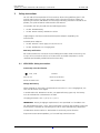
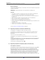
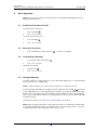
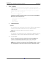
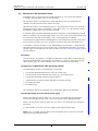
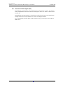
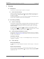
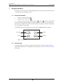
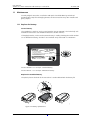
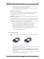
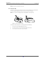
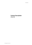
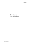
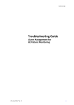
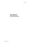
TD 92417GB
User Manual
Ascom a71 Alarm Transceiver and
Ascom p71 Transceiver
2009-03-11/ Ver. C
User Manual
Ascom a71 Alarm Tranceiver and Ascom p71 Transceiver
TD 92417GB
Contents
1 Introduction............................................................................................................. 1
1.1 Abbreviations and Glossary ................................................................................ 1
1.2 Ascom a71 and p71 Versions ............................................................................. 1
2 Description............................................................................................................... 2
2.1 General Design .................................................................................................. 2
2.2 Chargers ............................................................................................................ 5
2.2.1 Single Charger ........................................................................................... 5
2.2.2 RS232 Programming Device ....................................................................... 5
2.2.3 PCR Charging Rack .................................................................................... 5
2.3 Accessories ........................................................................................................ 6
3 Safety Instructions .................................................................................................. 7
3.1 ATEX/IECEx Safety Instructions ........................................................................... 7
3.2 Regulatory Compliance Statements (EU/EFTA only) ............................................. 8
3.3 Regulatory Compliance Statements (USA and Canada only) ............................... 8
4 Basic Operation ..................................................................................................... 10
4.1 Switch the Transceiver On/Off .......................................................................... 10
4.2 Mute the Transceiver ........................................................................................ 10
4.3 Lock the Keys Manually .................................................................................... 10
4.4 Charge the Battery ........................................................................................... 10
5 Alarm Functions .................................................................................................... 11
5.1 Push-button Alarms ......................................................................................... 11
5.2 Pull-cord Alarm ................................................................................................ 11
5.3 Man-down & No-movement Alarm .................................................................. 12
5.4 Acoustic Location Signal (ALS) .......................................................................... 13
5.5 Location Function (IR or LF) .............................................................................. 14
5.6 Special Location Function ................................................................................. 14
5.7 External Alarm ................................................................................................. 14
6 Messaging.............................................................................................................. 15
6.1 Messages List ................................................................................................... 15
6.1.1 Read a Stored Text Message ..................................................................... 15
6.2 Basic Message Handling ................................................................................... 15
6.2.1 Receive a Text Message ............................................................................ 15
6.2.2 Receive a Message with Request for Answer ............................................ 15
6.2.3 Delete a Message ..................................................................................... 15
6.3 Message Queue ............................................................................................... 16
6.4 Info Message ................................................................................................... 16
6.5 Configure the Soft Keys for Received Messages ................................................ 16
2009-03-11/ Ver. C
User Manual
Ascom a71 Alarm Tranceiver and Ascom p71 Transceiver
TD 92417GB
6.6 Data Send ........................................................................................................ 16
6.6.1 Data Send ................................................................................................ 16
6.6.2 Data Send with a Prefix ............................................................................ 16
7 Navigate the Menu ............................................................................................... 17
7.1 Enter/Exit the Menu ......................................................................................... 17
7.2 Shortcut Keys ................................................................................................... 17
8 Menu Tree .............................................................................................................. 18
8.1 Messages ........................................................................................................ 18
8.2 Profiles ............................................................................................................ 18
8.3 Services ........................................................................................................... 18
8.4 Settings .......................................................................................................... 19
9 Menu Operations .................................................................................................. 20
9.1 Messages ........................................................................................................ 20
9.1.1 Message List ............................................................................................ 20
9.1.2 Info Messages List .................................................................................... 20
9.1.3 Send Data ................................................................................................ 21
9.2 Profiles ............................................................................................................ 21
9.2.1 Change Profile ......................................................................................... 21
9.3 Services ........................................................................................................... 22
9.3.1 Activate a Service ..................................................................................... 22
9.4 Settings .......................................................................................................... 22
9.4.1 Change the Volume ................................................................................. 23
9.4.2 Increasing Volume On/Off ........................................................................ 23
9.4.3 Vibrator On/Off ........................................................................................ 23
9.4.4 Message Reminder On/Off ....................................................................... 23
9.4.5 Key Beep On/Off ...................................................................................... 23
9.4.6 Deactivate/Activate Man-down alarm ....................................................... 23
9.4.7 Deactivate/Activate No-movement alarm .................................................. 23
9.4.8 Deactivate/Activate Pull-cord alarm .......................................................... 23
9.4.9 Set Alarm Data ........................................................................................ 24
9.4.10 Change the Message Text Size ............................................................... 24
9.4.11 Backlight On/Off .................................................................................... 24
9.4.12 Change the Contrast ............................................................................. 24
9.4.13 Turn Automatic Key Lock On/Off ............................................................ 24
9.4.14 View Shortcut Keys ................................................................................ 24
9.4.15 Select Language ..................................................................................... 24
9.4.16 Group Numbers ..................................................................................... 25
9.4.17 Show Time and Date ............................................................................. 25
9.4.18 Set Time Format .................................................................................... 25
9.4.19 Set Date Format ..................................................................................... 25
2009-03-11/ Ver. C
User Manual
Ascom a71 Alarm Tranceiver and Ascom p71 Transceiver
TD 92417GB
9.4.20 Display System Information .................................................................... 25
9.5 System Test ...................................................................................................... 26
9.5.1 Coverage Test .......................................................................................... 26
9.5.2 Location Test ............................................................................................ 26
9.5.3 Error Log .................................................................................................. 26
9.5.4 GUI Test ................................................................................................... 26
9.5.5 MD/NM Test ............................................................................................ 26
10 Operation Notice................................................................................................. 27
10.1 Operation Condition ...................................................................................... 27
11 Maintenance........................................................................................................ 28
11.1 Replace the battery ........................................................................................ 28
11.2 Change the SIM Card .................................................................................... 29
11.3 Fasten the Clip ............................................................................................... 30
12 Related Documents ............................................................................................ 31
Appendix A: Programming the Transceiver ........................................................... 33
2009-03-11/ Ver. C
User Manual
Ascom a71 Alarm Tranceiver and Ascom p71 Transceiver
1
TD 92417GB
Introduction
This document describes the Ascom a71 Alarm Transceiver and p71 Transceiver. The
Ascom a71 Alarm Transceiver and p71 Transceiver included in the On Site Paging and
Personal Security System are easy to use and designed to function in tough environments.
The transceivers are described in default programmed version but additional functions and
factory settings are also included in the document, providing a full description of the
functionality.
Note that the system may not supply all functions described in this document. For
information about the system, please contact the supplier.
The following documents are recommended as a complement:
• System Description, Personal Security System, TD 90677GB
• System Description, On Site Paging System, TD 91034GB
1.1
1.2
Abbreviations and Glossary
ALS
Acoustic Location Signal. A ramped up signal that can be
played after an alarm from the transceiver.
IR
Infra Red
LED
Light Emitting Diode
LF
Low Frequency
PCR
Portable Charging Rack
PDM
Portable Device Manager
SIM
Subscriber Identity Module
System 900
Generic term for telePROTECT, teleCOURIER and CTS 900
systems.
Ascom a71 and p71 Versions
The transceivers are available in two versions, basic and advanced. Intrinsically safe (ATEX/
IECEx) versions are available as an option.
Functions
SIM card
Vibrator function
Messaging
Acknowledge
Group messaging
Data Send
Data with prefix
Availability information/Absence
Push-button alarm
Man-down & No-movement alarm
Pull-cord alarm
Acoustic Location Signal (ALS)
Location function*
Intrinsically safe (ATEX/IECEx)
a71 basic
a71 advanced
p71 basic
p71 advanced
Yes
Yes
Yes
Yes
Yes
Yes
Yes
Yes
Yes
Yes
Yes
-
Yes
Yes
Yes
Yes
Yes
Yes
Yes
Yes
Yes
Yes
Yes
Yes
Yes
Option
Yes
Yes
Yes
Yes
Yes
Option
Yes
Yes
Yes
Yes
Yes
Yes
Yes
Yes
-
* System dependent feature
001
Figure 1.
Figure 1. Function overview of the transceivers
Alarms are transmitted on the UHF band 420-475 MHz. The code format is compatible
with the System 900.
2009-03-11/ Ver. C
1
User Manual
Ascom a71 Alarm Tranceiver and Ascom p71 Transceiver
2
TD 92417GB
Description
This section describes the transceiver and available accessories.
Figure 2.
Soft key field
Pull-cord
Soft keys
OK key
C key
OK
C
Mute button
Navigation key
Menu key
LED
002
Return key
IR-receiver
Alarm button
Figure 2. Overview of the transceiver
2.1
General Design
Display
The icons and text in the display shows the current status.
Figure 3.
13:22
} Identity
John Doe
4321
Info
In charger
Doctor
Jobs
}
}
Call number & Status
Soft key field (User defined)
003
05:12:06
} Icon row
} Date & Time
Figure 3. Example of a display configuration in stand-by mode.
The display can be divided into the following segments:
•
•
•
•
•
•
Icon row - Shows information on active alarms, battery level.
Date & Time - Shows the date and time.
Identity - Shows the owner ID.
Call number - Shows the call number.
Status - Shows the status of the transceiver. For examples; In charger.
Soft key field - Shows the user defined function of the three soft keys beneath the
display.
2009-03-11/ Ver. C
2
User Manual
Ascom a71 Alarm Tranceiver and Ascom p71 Transceiver
TD 92417GB
Display Icons
The “Audio signal off” icon is shown when all alert signals,
including ring signal, message tone, key beep etc. are turned off.
High priority messages will however override this setting.
The “Battery” icon is always shown in the display in stand-by mode.
When the level is low it is time to charge the battery.
The “New message” icon appears when a new message is received.
The number on the right side of the icon shows the total number of
unread messages. The symbol will remain until the message is read.
The “Unread message” icon is added in front of not read messages
in the message list.
The “Read message” icon is added in front of read messages in the
message list.
The "Response required" icon is added in front of messages that
requires a response.
The "Response sent" icon is added in front of messages that has
been responded to.
The “Key” icon shows that the keypad is locked.
The “No-movement alarm on” icon shows that the no-movement
alarm is activated.
The “Man-down alarm on” icon shows that the man-down alarm is
activated.
The “Pull-cord alarm on” icon shows that the pull-cord alarm is
activated.
!
The "Error" icon appears when an error has occured. Service is
needed.
Menu Icons
“Messages”, see 9.1 Messages on page 20 for more information.
“Profiles”, see 9.2 Profiles on page 21 for more information.
“Services”, see 9.3 Services on page 22 for more information.
“Settings”, see 9.4 Settings on page 22 for more information.
2009-03-11/ Ver. C
3
User Manual
Ascom a71 Alarm Tranceiver and Ascom p71 Transceiver
TD 92417GB
Buttons
The transceiver has two buttons, see figure 2 on page 2.
Alarm button, used to send alarms. The button can also be used for test alarm. The
function of this button is configurable.
Mute button, used to silence the beep, vibrator and LED signals including the Acoustic
Location Signal (ALS).
Keys
The transceiver has eight keys, see figure 2 on page 2.
Soft Keys, the three soft keys are located just beneath the display and the function of
each soft key is shown by text in the display just above the keys. In stand-by mode the soft
keys can be used for specific functions defined by the administrator.
Navigation key,
, is used to control the movement of the cursor in the display.
OK
is used to confirm choices in the menu.
C
is used to delete messages and clear check boxes in the menu.
is used to step backwards when navigating in the menu tree.
is used to access/leave the menu.
Case
The case is made of durable PC/ABS plastic and is IP64 classified. The transceiver also fulfils
IEC 60068-2-32 procedure 1, which makes it drop proof from one meter onto concrete.
Ascom approves drops from 1.5 meters.
A transparent smoke coloured plastic item covers the IR receiver and the LED. A name
label is located next to the clip.
Antenna
The antenna used for communicating with the fixed system is integrated in the transceiver.
This makes the transceiver robust and easy to handle.
Clip, Hinge-Type
The clip on the back of the transceiver can be used to fasten the transceiver to a belt or
similar. It is also possible to change the clip to a swivel-type clip.
Battery
The battery is a rechargeable Li-lon battery.
Note: The a71 ATEX/IECEx Alarm Transceiver and the p71 ATEX/IECEx Transceiver must be
used with special ATEX/IECEx approved batteries.
SIM Card
All personal settings in the transceiver are programmed and stored in the SIM card. The
SIM card can easily be moved to another transceiver. By this it is easy to keep personal
settings, such as identity and alert signal. This can be handy in case of break down or
when changing operation environment and switching transceiver.
2009-03-11/ Ver. C
4
User Manual
Ascom a71 Alarm Tranceiver and Ascom p71 Transceiver
TD 92417GB
Pull-cord (Option)
004
Figure 4.
Figure 4. Pull-cord
The pull-cord is made of a ABS plastic attachment connected to a canvas ribbon. The end
of the ribbon has a clip which must be safely attached, for example, to the clothes. The
pull-cord is also used as a security string, which prevents the transceiver to fall to the
ground.
The transceiver can be used without the pull-cord option. Remove the pull-cord and plug
the hole with the provided ABS lid.
2.2
Chargers
2.2.1
Single Charger
The single charger is a separate unit used for charging the transceiver. Connect the single
charger by pushing it under the clip. The single charger is connected to a power supply
which has four exchangeable plug-in contacts which fit into an ordinary wall socket in
many countries.
005
Figure 5.
Figure 5. Single charger for the transceiver
For more information about the single charger, see Data Sheet, Single Charger,
TD 92353GB.
2.2.2
RS232 Programming Device
Similar to the single charger in design, the RS232 programming device is used to connect
the transceiver to a computer in order to upgrade the firmware and edit parameters. For
more information see, Appendix A: Programming the Transceiver on page 33.
2.2.3
PCR Charging Rack
The wall mounted PCR Charging Rack (PCR) is used for charging the transceivers. The PCR
is a modular system that consists of a master module (PCR-M), extension modules (PCR-E)
and power supplies. Each PCR module has six charging slots.
2009-03-11/ Ver. C
5
User Manual
Ascom a71 Alarm Tranceiver and Ascom p71 Transceiver
TD 92417GB
006
Figure 6.
Figure 6. PCR with power supply, one PCR-M and two PCR-E
One PCR-M can support up to 20 PCR-E, which gives a charging possibility of 126
transceivers. A power supply feeds up to three Charging Rack modules (one PCR-M and
two PCR-E), which results in seven power supplies for the above example.
Transceivers with a pull-cord/security string can be charged in the PCR Charging Rack
without removing the pull-cord.
For further information about the PCR refer to its Data Sheet, Portable Charging Rack,
TD 92355GB and Installation Manual, PCR Charging Rack, TD 92356GB.
Note: When charging an intrinsically safe ATEX/IECEx transceiver in a PCR Charging Rack,
the rack must be version 2A or higher.
2.3
Accessories
Belt Clip, Swivel Type
The ordinary belt clip can be replaced by a special swivel type, adapted to firmly place the
transceiver in the belt.
Leather Case
As accessory, there is a leather case especially designed for the transceiver used to increase
the protection of wear and tear. It is possible to use the transceiver while it is placed in the
case. The clip of the transceiver is not necessary to remove.
Name Label Kit
For the transceiver, a name label kit can be ordered. The name label is possible to use for
own means of identification.
2009-03-11/ Ver. C
6
User Manual
Ascom a71 Alarm Tranceiver and Ascom p71 Transceiver
3
TD 92417GB
Safety Instructions
For safe and efficient operation of the transceiver, observe the guidelines given in this
manual and all necessary safety precautions when using the transceiver. Follow the
operating instructions and adhere to all warnings and safety precautions located on the
product, the Quick Reference Guide and this User Manual.
This product shall only be used with the following batteries:
• Art.No.: 660089 Battery
• Art.No.: 660161 Battery ATEX/IECEx-version
Single chargers shall only be connected with power adapters supplied by the
manufacturer.
Available power adapters:
• Art.No.: 660109 Power supply unit AC/5V DC/1A
• Art.No.: 660093/2A PCR Charging Rack
Warranty notification
Do not disassemble the transceiver. Disassembling the handset voids the warranty. The
a71/p71 alarm transceiver consists of no consumer serviceable components. Service
should be performed by Authorized Service centre only.
3.1
ATEX/IECEx Safety Instructions
Intrinsically safe classification
II 2G, II 3D
EX ib IIC T4
EX ibD 22 IP64 T50°C
CE 0470
IECEx SIR 07.0033X
SIRA 07ATEX 2108X
Charge the battery
When charging an intrinsically safe ATEX/IECEx transceiver in a PCR Charging Rack, the
rack must be version 2A or higher.
In combination with ATEX/IECEx-version, use approved battery types only. The battery
must be marked with CHAT/ATEX on the label.
Charging parameters: Um = 5,25 V, Im = 1,25 A
IMPORTANT: Battery charging or replacement is NOT permitted in a hazardous area.
For approved battery types, see EC Type examination Certificate SIRA 07ATEX 2108X and
IECEx Scheme Certificate of Conformity IECEx SIR 07.003X and following supplements.
The document above and the EC Declaration of Conformity can be found at:
http://www.ascom.com/ws/products_ws.htm and http://www.iecex.com
2009-03-11/ Ver. C
7
User Manual
Ascom a71 Alarm Tranceiver and Ascom p71 Transceiver
TD 92417GB
Remove the battery
The rear cover holding the battery is fastened by a torx screw that requires the special tool
included in the delivery.
IMPORTANT: Removing the battery is NOT permitted in a hazardous area.
Attention
• The product is housed in an enclosure that meets IP64. However, the ATEX/IECEx
classified transceiver is not intended to be immersed in dust or water.
• In the case of damage suspect, do not use the ATEX/IECEx classified transceiver in a
hazardous area.
• Make sure that the product marking corresponds to the site requirements.
• Before installation consult the product documentation.
• National safety rules and regulations have to be observed.
• Do not use accessories to the product without ensuring that they are suitable for use in
a hazardous area.
• Modification of the product is not permitted.
• Product repair has to be done at authorised repair shops only.
See also Replace the ATEX/IECEx Battery on page 29.
3.2
Regulatory Compliance Statements (EU/EFTA only)
This equipment is intended to be used in the whole EU & EFTA.
This equipment is in compliance with the essential requirements and other relevant
provisions of R&TTE Directive 1999/51/EC. The Declaration of Conformity may be
consulted at:
http://www.ascom.com/ws/products_ws.htm
This equipment uses frequencies referring to different rules in the various EU&EFTA
countries.
A radio communication licence is in most cases neccessary for the use of the equipment.
The frequencies required for operation of the radio equipment must be notified and
assigned prior to usage of the equipment.
The transceiver is marked with the label
3.3
Regulatory Compliance Statements (USA and Canada only)
FCC compliance statements
This equipment has been tested and found to comply with the limits for a Class B digital
device, pursuant to part 15 of the FCC Rules. These limits are designed to provide
reasonable protection against harmful interference in a residential installation. This
equipment generates, uses and can radiate radio frequency energy and, if not installed
and used in accordance with the instructions, may cause harmful interference to radio
communications. However, there is no guarantee that interference will not occur in a
particular installation. If this equipment does cause harmful interference to radio or
television reception, which can be determined by turning the equipment off and on, the
2009-03-11/ Ver. C
8
User Manual
Ascom a71 Alarm Tranceiver and Ascom p71 Transceiver
TD 92417GB
user is encouraged to try to correct the interference by one or more of the following
measures:
• Reorient or relocate the receiving antenna.
• Increase the separation between the equipment and receiver.
• Connect the equipment into an outlet on a circuit different from that to which the
receiver is connected.
• Consult the dealer or an experienced radio/TV technician for help.
Information to user
This device complies with Part 15 of the FCC Rules. Operation is subject to the following
two conditions:
(1) this device may not cause harmful interference, and
(2) this device must accept any interference received, including interference that may
cause undesired operation
Modifications
Changes or modifications to the equipment not expressly approved by the party
responsible for compliance could void the user’s authority to operate the equipment.
2009-03-11/ Ver. C
9
User Manual
Ascom a71 Alarm Tranceiver and Ascom p71 Transceiver
4
TD 92417GB
Basic Operation
Note: The transceiver may have functions other than described, depending on the preprogrammed parameters.
4.1
Switch the Transceiver On/Off
To switch the transceiver on:
1
Press and hold
2
Press "Yes" soft key.
OK
.
To switch the transceiver off:
4.2
1
Press and hold
2
Press "Yes" soft key.
Mute the Transceiver
1
4.3
.
Press and hold the “Mute” button.
is shown in the display.
Lock the Keys Manually
1
In stand-by mode, shortly press
2
Press "Yes" soft key.
C
.
To unlock the keypad:
4.4
1
Shortly press
2
Press "Yes" soft key.
C
.
Charge the Battery
Charging is done in a single charger or a wall mounted charging rack. It is recommended
that the transceiver is charged daily.
Note: Charge the battery for at least two hours before it is used the first time.
A flashing orange LED indicates charging. A green steady LED and a filled
icon shows
a fully charged battery. It takes approximately two hours to charge the battery. An empty
battery icon in the display and a warning beep signal played once every minute together
with a fast flashing red LED indicates an empty battery. Put the transceiver into the charger
to load the battery.
To replace the battery, see Replace the Standard Battery on page 28.
Note: While charging, Man-down & No-movement alarms are automatically deactivated.
The Location Function (IR and LF) is also deactivated. (If a push-button alarm is sent, the
last stored location before charging the transceiver, is sent).
2009-03-11/ Ver. C
10
User Manual
Ascom a71 Alarm Tranceiver and Ascom p71 Transceiver
5
TD 92417GB
Alarm Functions
To secure a safe transmission of an alarm, every alarm is sent in two sequences. The
number of times to resend an alarm in each sequence is configurable with parameters and
is done in the PDM.
A beep/vibrator/LED signal can confirm that an alarm has been sent. These feedback
signals of a sent alarm are all configurable.
Common Alarm Configurations
The following parameters are common for the Test alarm, Personal alarm, Man-down &
No-movement and Pull-cord alarm types.
•
•
•
•
5.1
Number of alarm transmissions per sequence
Beep feedback
LED feedback
Vibrator feedback
Push-button Alarms
Test Alarm
Press and hold the "Alarm" push-button until "Test Alarm" is displayed. Depending on set
parameters, a beep is heard, the green LED flashes once and the vibrator stirs.
Note: Send a test alarm every day to test the transceiver and system.
Personal Alarm
Press the "Alarm" push-button twice or more. "Personal Alarm" is displayed. Depending
on set parameters, a beep is heard, the green LED flashes once and the vibrator stirs.
5.2
Pull-cord Alarm
An alarm is sent when the pull-cord is pulled off the transceiver. Depending on set
parameters, a beep/vibrator/LED signal confirms that the alarm has been sent.
The pull-cord must be attached more than 5 seconds to generate an alarm.
Note: Make sure that the clip of the pull-cord is safely attached to the clothes. To make a
test, remove the battery of the transceiver, pull the transceiver and make sure that the
pull-cord releases first.
2009-03-11/ Ver. C
11
User Manual
Ascom a71 Alarm Tranceiver and Ascom p71 Transceiver
5.3
TD 92417GB
Man-down & No-movement Alarm
Man-down alarm: If the transceiver is tilted more than 55º for a preset time (default
7 seconds), the Man-down alarm will be activated.
No-movement alarm: If no movement is detected during a preset time (default 30
seconds), the No-movement alarm will be activated.
Note that the alarm is not sent directly when it is activated. When the alarm is activated, a
warning message is shown in the display: "Man-down alarm" or "No-movement alarm"
depending on which alarm that has been activated.
A warning signal called Man-down/No-movement Warning is also heard during a period
(default 7 seconds). The warning signal always starts with a pair of low volume beeps and
then continues with high volume beeps, and is alternating with the vibrator.
The warnings message and the warning signal are activated until any button is pressed, or
until the alarm has been sent. Press any button to prevent the alarm from being sent.
If no button is pressed, the alarm is sent. Depending on set parameters, a beep/vibrator/
LED signal confirms that the alarm has been sent. If configured in the PDM, an acoustic
location signal is activated after the alarm has been sent, see 5.4 Acoustic Location Signal
(ALS) on page 13.
Extra Delay
If the parameter “Extra delay” is enabled, the detection of Man-down & No-movement
alarm can be disabled for a configurable time (default 10 minutes). When the warning
signal sounds, press the "Mute" button. Press "Yes" to activate the extra delay.
Configuration of Man-down & No-movement Alarm
The following parameters are configurable via the PDM:
•
•
•
•
•
•
Time of Man-down detection phase (time of a tilted state)
Time of No-movement detection phase (time of a non-moving state)
Time of Man-down/No-movement Warning phase
Automatically key lock off at Man-down/No-movement warning
Extra delay activation
Extra delay time
For information on how to configure, see Configuration Manual, TD 92439GB.
Activate Man-down or No-movement Alarm again
When a Man-down alarm has been sent, the alarm is activated again by moving the
transceiver to upright position, that is, the alarm button shall be pointed upwards.
When a No-movement alarm has been sent, the alarm is activated again by moving the
transceiver.
It is also possible to activate the alarms again by pressing the Mute button.
Note: If ALS is enabled, the Man-down or No-movement alarm can only be activated
again by pressing the Mute button.
2009-03-11/ Ver. C
12
User Manual
Ascom a71 Alarm Tranceiver and Ascom p71 Transceiver
5.4
TD 92417GB
Acoustic Location Signal (ALS)
Depending on set parameters, the ramped up ALS is played after an alarm. The signal is
always ramped from the lowest volume to the highest. Press the "Mute" button to turn
the ALS off.
Depending on the PDM settings, it is possible to make the user enter a password when
turning the ALS off. The password is the same as the login password.
ALS is configurable for Man-down & No-movement alarm, Push-button alarm and Pullcord alarm.
2009-03-11/ Ver. C
13
User Manual
Ascom a71 Alarm Tranceiver and Ascom p71 Transceiver
5.5
TD 92417GB
Location Function (IR or LF)
The location of the transceiver, received via either infrared light (IR) or low frequency
transmission (LF), is automatically sent along with an alarm.
If both IR and LF are enabled, the transceiver first handles IR and then LF. If a location is
detected, the location function is put to sleep until the next scan interval, which is defined
by a parameter. Depending on set parameters, a beep signal and/or a flashing green LED
indicates that a location (a new or the same) has been received.
007
Note: The top glass of a transceiver with an IR receiver must never be covered,
see figure 7.
Figure 7.
Figure 7. IR-function of transceiver.
Configuration of Location Function
The following parameters are configurable:
• Reading of location code interval
• Beep activation when receiving the location
• LED activation when receiving the location
5.6
Special Location Function
If the fixed locators are set to send a "special location code", the portable automatically
can send an alarm directly after it has received the code.
5.7
External Alarm
The portable can send either alarm or data when triggered by an incoming external alarm
signal. A Single Charger has to be modified for this purpose, see Configuration Manual,
Ascom a71 Alarm Transceiver and p71 Transceiver, TD 92439GB.
2009-03-11/ Ver. C
14
User Manual
Ascom a71 Alarm Tranceiver and Ascom p71 Transceiver
6
TD 92417GB
Messaging
6.1
Messages List
The twenty last received messages are stored in a message list.
6.1.1
Read a Stored Text Message
Open the message list by pressing
or from the menu. Navigate the list using
The selected message is highlighted. Press OK to read the message. Skip between
messages by using
.
.
If the clock and date function is set, the time when the message was received can be seen.
The time stamp is changed to a date stamp the following day.
6.2
Basic Message Handling
6.2.1
Receive a Text Message
The flashing LED, accompanied by a message tone and/or a vibrating transceiver, indicates
a message. The message tone can be silenced by a press on the "Mute" button. The
message tone will break through silent mode if the message is urgent. The message is
shown in the display.
An unread message is indicated with
in the display. In the message list, unread
messages are marked
. By pressing any key (not alarm) the received message is marked
as read
. When all unread messages are read, the
disappears.
6.2.2
Receive a Message with Request for Answer
A message with request for answer is indicated and viewed the same way as an ordinary
message, see 6.2.1 Receive a Text Message on page 15. Use the soft keys to do a positive
or negative acknowledgement.
Accept/Reject a Message
Press the soft key “Accept” or “Reject”. An acknowledged message is shown by the text
“Accepted” or “Rejected”.
6.2.3
Delete a Message
Delete a Received Message
Press C when the message is displayed. The question “Delete message?“ is shown; press
“Yes”.
Delete a Stored Text Message
Open the message list by pressing
, or from the menu. Navigate the list using
.
The selected message is highlighted. Press C . The question “Delete selected message?”
is shown. Press “Yes”.
2009-03-11/ Ver. C
15
User Manual
Ascom a71 Alarm Tranceiver and Ascom p71 Transceiver
6.3
TD 92417GB
Message Queue
If a new message is received while another message is read the new message will replace
the old message in the display. The old message will be placed in the message list.
6.4
Info Message
An info message is shown by the
icon in the display. Open the info message from the
menu. An Info message contains information that is updated frequently, such as
measurements in a production process, exchange rates, or stock market notations.
The transceiver can receive one info message per call number i.e. altogether six. When an
info message is displayed, the
symbol appears. The info messages are handled as a
message, see 6.2 Basic Message Handling on page 15 for more information.
6.5
Configure the Soft Keys for Received Messages
For every beep code (0-7) it is possible to configure the soft keys in the PDM. The
following can be done;
• define which soft keys are shown
• define the text on the soft keys
• define the action of the soft keys
Note: The possible actions are data send, data send with prefix, accept and reject.
6.6
Data Send
It is possible to send data from the transceiver by pressing a pre-programmed soft key or
selecting a service. Data send can be used for opening a door, starting/stopping a machine
etc. The configuration is done from the PDM.
6.6.1
Data Send
The data send function is accessed from the messages menu. The data can be predefined
when programming the soft key or service.
6.6.2
Data Send with a Prefix
Data send with a prefix is sent from the transceiver by pressing a pre-programmed soft key
or selecting a service and then entering data.
2009-03-11/ Ver. C
16
User Manual
Ascom a71 Alarm Tranceiver and Ascom p71 Transceiver
7
TD 92417GB
Navigate the Menu
The choices in the main menu is displayed graphically with symbols, while the alternatives
in the submenus are displayed as a list.
7.1
Enter/Exit the Menu
1
Enter the menu by pressing
.
2
Navigate in the menu using
3
Leave any menu screen by a single press on
.
or press
to return to idle mode.
The three soft keys below the display are used for choices in the menu. The function of
each soft key is explained by text in the soft key field in the display. Examples of functions
are; Save, Delete all, Yes, No etc.
The headline shows the selected icon, the icon itself is highlighted when selected.
Figure 8.
Messages
Profiles
Services
008
Settings
Figure 8. Menu icons
7.2
Shortcut Keys
In stand-by mode it is possible to assign the keys different functions using the PDM. To
check which function that is assigned to the shortcut keys, see 9.4.14 View Shortcut Keys
on page 24.
2009-03-11/ Ver. C
17
User Manual
Ascom a71 Alarm Tranceiver and Ascom p71 Transceiver
8
TD 92417GB
Menu Tree
8.1
Messages
Figure 9.
Message List
Received
Message 20
Info Message List
Message 1
Message 2
Enter data ...
Message 6
009
Send data
Message 1
Message 2
Figure 9. Messages tree
8.2
Profiles
Figure 10.
Profile settings ...
010
Normal
Silent
Loud
Profile 3
Profile 4
Figure 10. Profiles tree
8.3
Services
Figure 11.
Name: .....
Function:
Soft keys: .....
Service 12
Data send
Data with prefix
011
Service 1
Service 2
Figure 11. Services tree
2009-03-11/ Ver. C
18
User Manual
Ascom a71 Alarm Tranceiver and Ascom p71 Transceiver
8.4
TD 92417GB
Settings
Alert Signals
Volume Level
Increasing Volume
Vibrator
Message Reminder
Key Beep
Silent, Level 1 - 5
On/Off
On/Off
On/Off
On/Off
Alarm Settings
Man-down Alarm
No-movement Alarm
Pull-cord Alarm
Alarm Data
On/Off
On/Off
On/Off
Enter alarm data
Display
Text Size
Contrast
Backlight
Small, Medium, Large
5 levels
On/Off
Locks
Auto Key Lock
On/Off
Shortcut keys
Left Soft key
Middle Soft key
Right Soft key
OK key
C key
Return key
Navigation key
Up, Down, Left, Right
General
Language
Group Numbers
Time and Date
(Owner ID)
System
Information
Test
English, etc ...
Entry 1, Entry 2 ...
Time ...
Date ...
Show Time and Date
SW version, etc ...
Coverage
Location
Error Log
GUI Test ...
MD/NM Test
012
Figure 12.
Figure 12. Settings tree
Note: The "Alarm Settings" menu is enabled by default, but can be disabled via the PDM.
See Configuration Manual, TD 92439GB for more information.
2009-03-11/ Ver. C
19
User Manual
Ascom a71 Alarm Tranceiver and Ascom p71 Transceiver
9
TD 92417GB
Menu Operations
A parameter setting in the SIM card determines if changes that are made from the menu is
saved on the SIM card. If changes are not saved on SIM, they will be discarded when the
transceiver is restarted.
9.1
Messages
Here are all received messages and info messages listed.
1
Enter the menu by pressing
2
Select “Messages” and press
9.1.1
.
OK
.
Message List
To enter the received messages list:
1
Select “Received” and press
2
OK
.
Select "Message List" and press
OK
.
Figure 13.
Navigate the message list using
unread.
. All messages are either marked as read or
Read a Message
1
Press OK . The message is displayed and the date and time it was received is shown.
Skip between messages by using
.
2
Press
to return to the message list.
Delete a Message
1
Press
2
Press “Yes”. The handset will automatically return to the message list.
C
; the question “Delete message?” will appear.
Delete all Messages
1
Press “Delete all” from the message list. The question “Delete all messages?” will
appear.
2
Press “Yes” (“No” will return to the message list); “All messages deleted” is shown
and after one second the transceiver will return to stand-by mode.
9.1.2
Info Messages List
The info message list is handled the same way as the message list. To enter the info
messages list:
1
Select “Received” and press
2
Select "Info Message List" and press
Navigate the info message list using
or unread.
2009-03-11/ Ver. C
OK
.
OK
.
. All info messages are either marked as read
20
User Manual
Ascom a71 Alarm Tranceiver and Ascom p71 Transceiver
9.1.3
TD 92417GB
Send Data
The data send function can be used for opening a door, starting/stopping a machine etc.
9.2
1
Press
.
2
Select "Messages".
3
Select “Send Data”.
4
Use
5
• To insert a digit in the middle of the text string, press "Edit", use
where to insert the digit.
• Press "Insert" and insert the digits.
• To remove previous digit, press C .
Enter data and press “Send”.
to mark a digit in the virtual digit pad, press
OK
to select the digit.
to select
Profiles
It is possible to for the user to define up to five different profiles in the transceiver. Three
profiles are preset at delivery; Normal, Silent and Loud.
1
Enter the menu by pressing
2
Select “Profiles” and press
3
.
OK
.
Navigate the Profiles list using
.
Figure 14.
Profiles
013
Normal
Silent
Loud
Profile 3
Figure 13. Profiles list
The profiles are configured in the PDM and can, for example, consist of different ring
signals and volumes. Another example is when several users are sharing the same
transceiver. Each user can then define their own settings, for example; type of ring signal,
volume, soft key settings etc.
9.2.1
Change Profile
To change profile:
1
Select “Profiles” and press
2
Select the profile with
3
Press OK . The name of the marked profile is shown. The transceiver will
automatically return to the profiles list.
OK
. A list with all profiles is shown.
.
A soft key can be programmed to change profiles, see Configuration Manual for more
information.
2009-03-11/ Ver. C
21
User Manual
Ascom a71 Alarm Tranceiver and Ascom p71 Transceiver
9.3
TD 92417GB
Services
Twelve different services can be defined in the transceiver. The services are configured in
the PDM, for more information, see Appendix A: Programming the Transceiver on page
33.
1
Enter the menu by pressing
2
.
Select “Services” and press
OK
, a list with all created services is shown.
Figure 15.
Services
Lab door
Get lab results
Require wheelchair
Lock
Close
014
Open
Figure 14. Services list
9.3.1
9.4
Activate a Service
1
Select the desired service in the service list using
.
2
Press OK or soft key; to activate the service. If data is sent, the text “Sending” is
shown. The transceiver will automatically return to the list and the selected service
is marked.
Settings
It is possible for the user to change the settings. The alternatives are; Alert signals, Alarm
settings, Display, Locks, Shortcut keys, General and System.
1
Enter menu by pressing
2
Select “Settings” and press
3
Use
.
OK
, a list with the settings options is shown.
to navigate the Settings menu.
Figure 16.
Settings
>
015
Alert Signals
Alarm Settings
Display
Locks
Figure 15. Settings menu
•
•
•
•
Alert Signals; change the settings for all audible signals and the vibrator.
Alarm Settings1; turn the alarms on/off.
Display; change the text size and contrast, turn backlight on/off.
Locks; select if the keys are automatically locked.
1. The "Alarm Settings" menu is enabled by default, but can be disabled via the PDM, see Configuration Manual, TD
92439GB for more information.
2009-03-11/ Ver. C
22
User Manual
Ascom a71 Alarm Tranceiver and Ascom p71 Transceiver
TD 92417GB
• Shortcut Keys; view which function that is assigned to each shortcut key.
• General; change the following settings: Language, Group Numbers, Time and Date.
• System; view information about the system and access test functions.
9.4.1
Change the Volume
1
Select “Alert Signals” and press
2
Select “Volume Level” and press OK . Select the desired volume level by using
There are six available alternatives; Silent and level 1 to 5.
3
Activate the choice by pressing “Save” or
return to the Alert Signals list.
9.4.2
OK
.
Select “Alert Signals” and press
2
Select “Increasing Volume” and press
selected/cleared.
OK
.
OK
; the Increasing Volume checkbox is
Vibrator On/Off
1
Select “Alert Signals” and press
2
Select “Vibrator” and press
9.4.4
Message Reminder On/Off
OK
OK
.
; the Vibrator checkbox is selected/cleared.
1
Select “Alert Signals” and press
2
Select “Message reminder” and press
selected/cleared.
9.4.5
. The transceiver will automatically
Increasing Volume On/Off
1
9.4.3
OK
OK
.
OK
; the Message reminder checkbox is
Key Beep On/Off
1
Select “Alert Signals” and press
OK
2
Select “Key Beep” and press
; the Key Beep checkbox is selected/cleared.
9.4.6
OK
.
Deactivate/Activate Man-down alarm
1
Select “Alarm Setting” and press
2
Select “Man-down alarm” and press
selected/cleared.
9.4.7
OK
.
OK
; the Man-down alarm checkbox is
Deactivate/Activate No-movement alarm
1
Select “Alarm Setting” and press
2
Select “No-movement alarm” and press
selected/cleared.
9.4.8
.
OK
.
OK
; the No-movement alarm checkbox is
Deactivate/Activate Pull-cord alarm
1
Select “Alarm Setting” and press
2
Select “Pull-cord alarm” and press
cleared.
2009-03-11/ Ver. C
OK
.
OK
; the Pull-cord alarm checkbox is selected/
23
User Manual
Ascom a71 Alarm Tranceiver and Ascom p71 Transceiver
9.4.9
TD 92417GB
Set Alarm Data
Alarm data is a string of up to 15 characters (digits) which is sent together with the alarm.
1
Select “Alarm Setting” and press
OK
2
Select “Alarm Data” and press
.
3
Use
digit.
4
OK
.
to mark a digit in the virtual number pad, press
OK
to select the
• To insert a digit in the middle of the text string, press "Edit", use
where to insert the digit.
• Press "Insert" and insert the digit.
• To remove previous digit, press C .
Press "Save" and "Yes" to save the Alarm Data string.
to select
9.4.10 Change the Message Text Size
1
Select “Display” and press
2
Select “Text Size” and press
3
Choose between Large Size, Medium Size and Small Size. Press
OK
.
OK
.
OK
.
9.4.11 Backlight On/Off
1
Select “Display” and press
2
Select “Backlight” and press
OK
.
OK
; the Backlight checkbox is selected/cleared.
9.4.12 Change the Contrast
1
Select “Display” and press
2
Select “Contrast” and press
3
Select the desired contrast by using
OK
.
OK
.
then press “Save” or
OK
.
9.4.13 Turn Automatic Key Lock On/Off
1
Select “Locks” and press
2
Select “Auto Key Lock” and press
cleared.
OK
.
OK
; the Auto key lock checkbox is selected/
In stand-by mode a locked transceiver is indicated by
in the display.
9.4.14 View Shortcut Keys
The keys can be assigned different functions in the PDM. To check which function that is
assigned to the shortcut keys:
1
Select “Shortcut keys” and press
2
Select a key and press
OK
OK
.
. Information about the assigned function is displayed.
9.4.15 Select Language
1
Select “General” and press
2
Select “Language” and press
3
Select the desired language using
4
Press
2009-03-11/ Ver. C
OK
OK
.
OK
.
.
. The language is shown.
24
User Manual
Ascom a71 Alarm Tranceiver and Ascom p71 Transceiver
TD 92417GB
9.4.16 Group Numbers
Group numbers makes it possible to send a message to multiple handsets. The group
numbers are defined in the PDM. To activate group number, do the following:
1
Select “General” and press
2
Select "Group Numbers" and press
3
Select the group number using
4
Press
OK
OK
.
OK
.
.
; the selected group number checkbox is selected/cleared.
9.4.17 Show Time and Date
Depending on system setting, this function is available.
1
Select “General” and press
2
Select “Show Time and Date” and Press
selected/cleared.
OK
.
OK
. The Show Time and Date checkbox is
9.4.18 Set Time Format
1
Select “General” and press
2
Select “Time and Date” and press
3
Select "Time" and press
4
Scroll to preferred Time format using
5
Press
OK
OK
OK
.
OK
.
.
.
.
9.4.19 Set Date Format
1
Select “General” and press
2
Select “Time and Date” and press
3
Select "Date" and press
4
Scroll to preferred Date format using
5
Press
OK
OK
OK
.
OK
.
.
.
.
9.4.20 Display System Information
1
Select “System” and press
2
Select “Information” and press
versions etc. is displayed.
2009-03-11/ Ver. C
OK
.
OK
, information about hardware ID and software
25
User Manual
Ascom a71 Alarm Tranceiver and Ascom p71 Transceiver
9.5
TD 92417GB
System Test
System test menu is activated from the PDM.
1
Select “Settings” and press
2
Select “System” and press
3
Select “Test” and press
9.5.1
OK
OK
OK
.
.
.
Coverage Test
To display the RSSI value:
1
Select “Coverage” and press
2
The RSSI should typically have a value above 100 to ensure sufficient coverage.
9.5.2
.
OK
Location Test
To display the current (latest received) location:
1
9.5.3
Select "Location" and press
OK
.
Error Log
To view the error log:
1
9.5.4
Select “Error Log” and press
OK
, a list of recent system errors (if any) is displayed.
GUI Test
To test features such as LEDs, screen, backlight, vibrator, and beeps:
1
Select “GUI Test” and press
2
Select the feature to test and press
9.5.5
OK
.
OK
.
MD/NM Test
To test Man-down alarm and No-movement alarm:
1
2009-03-11/ Ver. C
Select “MD/NM Test” and press
OK
.
26
User Manual
Ascom a71 Alarm Tranceiver and Ascom p71 Transceiver
10
TD 92417GB
Operation Notice
10.1 Operation Condition
Transceiver
Only use the transceiver in temperatures from -10 o C to +55 oC (+40 oC for ATEX/IECEx).
Avoid exposing in direct sunlight and other heat sources.
Battery
Cautions
•
•
•
•
•
•
Do not immerse in water or throw into fire
Do not disassemble
Dispose of properly
Do not expose to high temperature (140F/60oC)
Use only specified chargers
Do not short-circuit
Note: When charging an intrinsically safe ATEX/IECEx transceiver, in a PCR Charging Rack,
the rack must be version 2A or higher.
IMPORTANT: Charging or replacement of an ATEX/IECEx battery is NOT permitted in a
hazardous area.
2009-03-11/ Ver. C
27
User Manual
Ascom a71 Alarm Tranceiver and Ascom p71 Transceiver
11
TD 92417GB
Maintenance
Use only original accessories. Installation and repairs should be done by authorised
personnel only. Keep the recharging contacts on the transceiver away from metallic and
greasy objects.
11.1 Replace the battery
Correct battery
The standard a71 and p71 use the same batteries (Art.No. 660089). The intrinsically safe
ATEX/IECEx transceivers use ATEX/IECEx-batteries (Art.No. 660161).
If changing batteries, make sure the correct battery is used by checking the article number.
On an ATEX/IECEx-battery, the label is also marked “Only to be used in CHAT/ATEX”.
Lithium Ion Battery
3.7V 650mAh
660161
> CAUTIONS <
- DO NOT DISASSEMBLE
- DISPOSE OF PROPERLY
- DO NOT EXPOSE TO HIGH TEMPERATURE (140F/60C)
- USE ONLY SPECIFIED CHARGERS
- DO NOT SHORT-CIRCUIT
Only to be used in CHAT/ATEX
Manufactured by Ascom (Sweden) AB
XX-XX
17.
Grimbodalen 2, Sweden
NL
Figure
Art.No. 660089 = a71 and p71 standard battery
Art.No. 660161 = a71 and p71 ATEX/IECEx-battery
Replace the Standard Battery
The plastic plate at the back of the transceiver is used to lock/unlock the battery lid.
1
2
3
016
Figure 18.
Figure 16. Battery replacement.
2009-03-11/ Ver. C
28
User Manual
Ascom a71 Alarm Tranceiver and Ascom p71 Transceiver
TD 92417GB
1
Push the plate to release the battery lid, see (1). Remove the lid and the battery.
2
Insert the new battery into the battery compartment (2).
3
Fasten the battery lid, note that the hooks of the rear shall be inserted first. Then
close the lid and secure it by pulling the plate (3).
Replace the ATEX/IECEx Battery
In combination with ATEX/IECEx-versions use approved battery types only. The battery
must be marked with CHAT/ATEX on the label, see Correct battery on page 28.
Charging parameters: Um = 5,25 V, Im =1,25 A
IMPORTANT: Charging or replacement of an ATEX/IECEx battery is NOT permitted in a
hazardous area.
For approved battery types, see EC Type examination Certificate SIRA 07ATEX 2108X and
IECEx Scheme Certificate of Conformity IECEx SIR 07.003X and following supplements.
The documents mentioned above and the EC Declaration of Conformity can be found at:
http://www.ascom.com/ws/products_ws.htm and www.IECEX.com
1
The rear cover holding the battery is fastened by a torx screw that requires the
special tool included in the delivery; Battery pack opener for ATEX.
Removing the ATEX/IECEx battery is NOT permitted in a hazardous area.
2
Remove the battery lid and the battery by removing the torx screw.
3
Insert the new battery, check that it is the correct battery, see Correct battery on
page 28, into the battery compartment (see figure 16 on page 28.)
4
Attach the battery lid with the torx screw.
11.2 Change the SIM Card
Note: It is recommended that the SIM card is changed in an environment without static
electricity.
Figure 19.
3
1
2
017
4
Figure 17. Removal and replacement of the SIM card.
1
Remove the battery, see Replace the Standard Battery on page 28. The SIM card is
placed under the battery unit in a hatch.
2
Press down the flexible stop (1) and move the SIM card back as far as possible (2).
Be sure that the SIM card is entirely out of the hatch before removing it. The easiest
way to ensure this is to turn the transceiver upside down and let the SIM card fall
out in the hand.
3
To insert the SIM card do the following: Put down the SIM card flat on the flexible
stop (3) and push it carefully into the hatch (4).
2009-03-11/ Ver. C
29
User Manual
Ascom a71 Alarm Tranceiver and Ascom p71 Transceiver
TD 92417GB
Note: Be careful not to bend the SIM card.
11.3 Fasten the Clip
The clip has a special release function to prevent it from breaking when strained. When
the clip is released and becomes slack, just snap it back with a hard press.
Note: This is also how a hinge-type clip is exchanged by a swivel-type clip.
Figure 20.
Figure 21.
2
3
018
1
Figure 18. How to restore the clip.
If the clip has fallen entirely off its fastening, perform the following:
1
Put the axle in the closed hinge on the clip (1).
2
Push the axle until it snaps into the open hinge in the clip (2).
3
Press firmly on the clip until it snaps into place.
2009-03-11/ Ver. C
30
User Manual
Ascom a71 Alarm Tranceiver and Ascom p71 Transceiver
12
TD 92417GB
Related Documents
Installation and Operation Manual, Portable Device Manager,
Windows version
TD 92325GB
Quick Reference Guide, a71 Alarm Transceiver and p71
Transceiver
TD 92418GB
System Description, Personal Security System
TD 90677GB
System Description, On Site Paging System
TD 91034GB
Configuration Manual, Ascom a71 Alarm Transceiver and p71
Transceiver
TD 92439GB
Installation Manual, PCR Charging Rack
TD 92356GB
Data Sheet, Portable Charging Rack
TD 92355GB
Data Sheet, Single Charger
TD 92353GB
2009-03-11/ Ver. C
31
User Manual
Ascom a71 Alarm Tranceiver and Ascom p71 Transceiver
TD 92417GB
Document History
For details, see change bars in the document.
Version
Date
A
2007-04-20 First Released version
B
2007-10-18 Inserted info about ATEX/IECEx and Regulatory Compliance
Statements
C
2009-03-11 Chapter 5.3 Man-down & No-movement Alarm: Added that
"Man-down and No-movement Alarm" is configured in the
PDM. Clarified that the warning message is displayed until
the alarm is cancelled or sent. "Automatically key lock off at
Man-down/No-movement warning" added.
Chapter Activate Man-down or No-movement Alarm again
added.
Chapter 8.4 Settings: Note added.
Chapter 9.4 Settings: Footnote added.
2009-03-11/ Ver. C
Description
32
User Manual
Ascom a71 Alarm Tranceiver and Ascom p71 Transceiver
TD 92417GB
Appendix A: Programming the Transceiver
The transceiver is programmed using the Portable Device Manager (PDM) software PDMSB. To program the transceiver do as below:
1
Connect the RS232 Programming Adapter to the computer.
2
The computer COM port corresponding to the RS232 Programming Adapter and
the COM port settings for the PDM software must match. The PDM software uses
default COM port 1, which can be changed, see Installation and Operation Manual,
Portable Device Manager, TD 92325GB.
Note: If the software upgrade interrupted, for example if the cable is removed, the
transceiver turns to download mode. When the transceiver is connected again, the New
portable connected window appears. Select “Edit but don’t save” > "OK".
Figure 22.
Figure 19. Connect new portable
The portable is added as an "unknown" entry in the PDM.
Figure 23.
Figure 20. Unknown portable
Repeat the software upgrade for this unit again. The software upgrade is successfully
performed when the Call No. of the portable changes from <unknown> to its real Call No.
and gets online.
Figure 24.
Figure 21. New portable added
2009-03-11/ Ver. C
33
User Manual
Ascom a71 Alarm Tranceiver and Ascom p71 Transceiver
TD 92417GB
Editing Parameters
When delivered, the transceiver parameters is pre-programmed. If any settings should be
changed, the PDM can be used to edit the parameters. For instructions on how to edit
parameters, see Configuration Manual, Ascom a71 Alarm Transceiver and p71 Transceiver,
TD 92439GB.
Note: If the transceiver is ordered without customer programming, the Call number has to
be set before editing other parameters.
Upgrading the Firmware
Follow the instructions in Installation and Operation Manual, Portable Device Manager,
TD 92325GB.
2009-03-11/ Ver. C
34