1
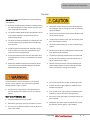
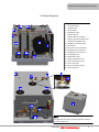
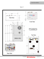
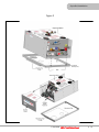
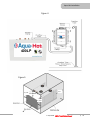
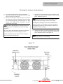
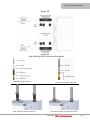
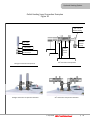
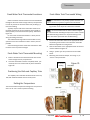
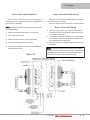
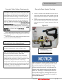
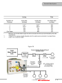
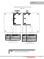
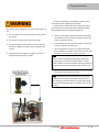
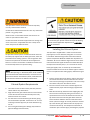
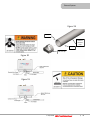
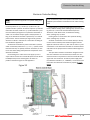
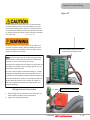
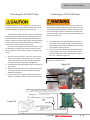
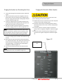
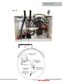
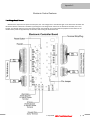
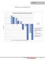
INSTALLATION MANUAL 400 SERIES 400-LP Section #: Title Introduction & Cautions About the Aqua-Hot 400-LP The Aqua-Hot 4OOLP is a hydronic (water based) heating system, and tank-less hot water system. The heating system provides moist, quiet, comfortable, interior heat. It is equipped with up to five separate thermostatically-controlled temperature zones and prevents tank and line freezing in the bays. The tank-less hot water system produces 90 gallons per hour of continuous, on-demand, hot water. This TribridHot™ designated system uses one or a combination of heat sources to heat FDA-approved “Generally Recognized as Safe” (GRAS) propylene glycol based antifreeze solution in the Aqua-Hot’s boiler tank. The 400LP uses one 120 Volt-AC, 1650 Watt electric element to heat the system when shore power is available, and a 12 Volt-DC powered propane burner when dry camping. The heat sources can be used separately or together. Should additional assistance be needed, please contact the Product Application Department at 1-800-685-4298, Monday through Friday, between the hours of 7 a.m. and 4 p.m. Mountain Time. Caution Notes As you read this Information, take particular note of the NOTICE, CAUTION, WARNING and DANGER symbols when they appear. This information is important for safe and efficient use of the Aqua-Hot equipment. NOTICE signals a situation where potential damage to the equipment could occur. CAUTION signals a situation where potential harm or risk of minor or moderate injury could occur if you do not follow instructions. WARNING signals a hazardous situation where potential harm, risk of serious injury or death could result if you do not follow instructions. DANGER signals a situation where immediate risk of serious injury or death will result if you do not follow instructions. NOTE In addition, this manual may indicate an IMPORTANT NOTE that highlights information that is especially important. © Aqua-Hot® 400-LP Installation Manual p. 3 Index Section #: Title Contents Aqua-Hot 400-LP Installation Manual Introduction & Cautions ................................................ 3 Section 1: Aqua-Hot Hydronic Heating System Safety Instructions & Precautions ................................ 5 Heating System Features .............................................. 6 Cut-Away Diagrams ........................................................ 7 Section 2: Aqua-Hot Installation Installing the Mounting Tray and Aqua-Hot .................. 8 Installing the Expansion Tank ....................................... 8 Pressure Testing the Aqua-Hot ..................................... 8 Aqua-Hot Measurement diagrams ...........................9-12 Section 3: Hydronic Heating System Heat Exchanger Location and Clearances ................. 13 Heat Exchanger Mounting Requirements .................. 13 Heat Exchanger Floor Plan .......................................... 14 Mounting the Heat Exchangers ................................... 15 Heat Exchanger Measurement diagrams ................... 16 Wiring the Heat Exchanger .................................... 17-18 Plumbing Requirements .............................................. 19 Plumbing the Hydronic Heating System ............... 20-22 Section 4: Thermostats Fresh Water Tank Thermostat Locations ................... 23 Fresh Water Tank Thermostat Mounting .................... 23 Positioning the Bulb and Capillary Tube ..................... 23 Setting the Temperature ............................................. 23 Fresh Water Tank Thermostat Wiring ......................... 23 Room Thermostat Locations ....................................... 24 Room Thermostat Mounting ....................................... 24 Room Thermostat Wiring ............................................. 24 Section 5: Domestic Water System Domestic Water System Requirements ..................... 25 Domestic Water System Plumbing ....................... 25-26 Section 6: Switch Panel Switch Panel Location ................................................. 27 Switch Panel Mounting ................................................ 27 Switch Panel Wiring ..................................................... 27 Switch Panel Rear View ............................................... 28 Section 7: Fuel System Fuel System Requirements ......................................... 29 Fuel System Installation .............................................. 29 Section 8: Exhaust System Exhaust System Requirements ................................... 30 Installing the Exhaust System ............................... 30-32 Section 9: Electronic Controller Wiring Electronic Controller Wiring .................................. 33-34 Wiring Harness Connection......................................... 34 Connecting the 12V DC Power .................................... 35 Connecting the 120V AC Power .................................. 35 Section 10: Purging the System Purging the Hydronic Heating System ........................ 36 Purging the System by Grounding the Zone............... 37 Purging the Domestic Water System .................... 37-38 Safety Instructions & Precautions .............................. 39 Purging the Propane System ...................................... 40 Section 11: Initial Start-up Activating the Aqua-Hot .............................................. 40 Appendices Appendix A: Wiring Diagram ........................................ 41 Appendix B: Wire Gauge Information ......................... 42 Appendix C: Electronic Controller Features .......... 43-44 Appendix D: Antifreeze Types...................................... 45 Appendix E: Antifreeze Mixture Quality....................... 45 Appendix F: Antifreeze Terms & Mixture Ratio .... 46-47 Appendix G: Measuring Antifreeze Refractometer48-49 © Aqua-Hot® 400-LP Installation Manual p. 4 Section #: Title Safety Instructions & Precautions The Unit IMPORTANT NOTE: Read all instructions before installing this appliance. Read this Installation Manual before installing or using the Aqua-Hot System to reduce the risk of injury to persons or damage to equipment. Disconnect electric wiring to the Aqua-Hot System before welding or plasma cutting the coach to avoid damage to equipment. The product identity label contains specifications of the unit, to what standard it has been tested, and important safety notices. Air pressure to the tank must not exceed 20 PSI or will cause internal damage. The Aqua-Hot must be installed in a compartment that is closed off from living quarters and accessible only from outdoors. The Aqua-Hot’s exhaust is HOT and must be kept away from heat sensitive material. Use caution when working on or near the propane gas system. DO NOT connect the 12 Volt-DC power to the Aqua-Hot if the vehicle requires welding. Propylene glycol based antifreeze “Generally Recognized as Safe” by the FDA must be utilized for antifreeze and water heating solution. An interlock switch prevents the Aqua-Hot heater from operating when the cover is not installed in the correct position. At maximum operating temperatures, the coolant will be very hot and scalding hot vapor or coolant may result in serious burns or injury. Should any additional assistance be needed, please contact the Product Application Department at 800685-4298 or 303-651-5500. DO NOT activate the burner until the antifreeze and water heating solution has been added to the boiler tank to avoid serious damage to the heater. Do not start the vehicle’s engine or electric generator. Contact the nearest gas supplier or qualified service technician for repairs. If you cannot reach a gas supplier or qualified service technician, contact the nearest fire department. Do not turn on the gas supply until the gas leak(s) has been repaired. Installation and service must be performed by a qualified installer, service agency, or gas supplier. If this information in these instructions is not followed exactly, a fire or explosion may result causing property damage, personal injury, or death. Do not store or use gasoline or other flammable vapors and liquids in the vicinity of this or any other appliance. WHAT TO DO IF YOU SMELL GAS Evacuate all persons from the vehicle. Shut off the gas supply at the gas container or source. Do not touch any electrical switch or use any phone or radio in the vehicle. © Aqua-Hot® 400-LP Installation Manual p. 5 Section #: Title Aqua-Hot Heating System Features 400-LP Features The product label attached to each Aqua-Hot provides a ready reference to specifications, test standards, and important safety notices. Propane Burner Heat Input (Firing Rate) Fuel Consumption (Continuous) 51,663 BTU/h 0.72 g/h Electric Heating Element Specifications Voltage/Maximum Power Consumption 120 VAC/1650 W 12 VDC/60 W Zone Heat Circulation Pumps Voltage/Maximum Power Consumption 2 12VDC/21 W Heating Zones Maximum 5 Domestic Water Heating Capacity with continuous supply On-Demand Specifications Dimensions 12”H x 18.5”W x 29.5”L Dry Weight Wet Weight 127 lbs. 184 lbs. NOTICE All vehicle installations must comply with the requirements listed in the Recreational Vehicle Industry Association’s (RVIA) ANSI/NFPA 1192 Handbook for Recreational Vehicle Standards. To receive a copy of this handbook and other pertinent RVIA Standards, write to: Recreation Vehicle Industry Association, 1896 Preston White Drive, P.O. Box 2999, Reston, VA 22090-0999, call them at (703) 620-6003, or online at www.rvia.org, www.nfpa.org. © Aqua-Hot® 400-LP Installation Manual p. 6 Section #: Title Aqua-Hot Heating System Features Cut-Away Diagrams 13 1. 2. 3. 4. 5. 6. 7. 8. 9. 10. 11. 12. 13. 14. 15. 16. 17. 18. 19. 20. 21. 14 2 1 6 16 7 18 20 11 8 3 17 AC Terminal Block AC Terminal Port AC Wiring Port Access Cover Air Release Valve Propane Burner Propane Burner Controller Propane Fuel Inlet/Outlet Ports Domestic Cold Water Inlet Domestic Hot Water Outlet Drain Valve Expansion Tank Connection Heating Zone 1 Outlet Port Heating Zone 2 Outlet Port Tempering Valve VAC Access Panel Wiring and Harness Port Zone 1 Circulation Pump Zone 1 Inlet Port Zone 2 Circulation Pump Zone 2 Inlet Port 5 12 21 19 4 15 9 10 NOTE: Service parts and accessories are available through Aqua-Hot Factory Authorized Service Center or at www.aquahot.com. © Aqua-Hot® 400-LP Installation Manual p. 7 Section #: Title Aqua-Hot Installation Installing the Mounting Tray and the The Aqua-Hot must be installed in a compartment that is completely closed off from living quarter and accessible only from the outdoors. 1. Reference the following illustrations for mounting information: - Overall Aqua-Hot dimensions. Reference Figure 1. Installing the Expansion Tank Select a mounting location that allows for easy access and clear visibility whenever the particular storage bay door is open. NOTE: The top of the expansion tank should always be mounted at least 4 inches higher than the highest point on the Aqua-Hot. Reference Figure 4. - Mounting Tray Information. Reference Figure 2. - I.D. Label noting the “Open Access” clearance requirement for the front of the heater. Reference Figure 5. - Service Access Clearance. Reference Figure 5. NOTE: Be sure to complete the following when installing the Aqua-Hot Inspect the area beneath the mounting location to ensure that no structural members will interfere with the cut-out for the mounting tray. Verify than an adequate support system, has been provided for the Aqua-Hot. 2. Cut out the required mounting tray opening. Reference Figure 2. 3. Install the mounting tray flange into the cut-out opening. Reference Figures 2 and 3. 4. Insert a #10 machine screw into each of the embossed holes in the mounting tray (total of six required) and tighten to secure the mounting tray to the motorhome. NOTE: Secure the mounting try into place prior to installing the Aqua-Hot. 1. Mount the expansion tank as illustrated in Figure 4. 2. Connect and clamp the overflow tubing from the expansion tank to the Aqua-Hot’s expansion tank connection. Reference Figure 4. 3. Drill a hole in the bay floor and connect (secure with a clamp) a long piece of overflow tubing so that it can be connected to the top of the expansion tank and extend through the bay floor. NOTE: Avoid any dips and bends in the overflow tubing from the Aqua-Hot to the expansion tank as air can become trapped in these dips and bends. This will prevent the expansion of the heating solution from properly depositing in the expansion tank. Pressure Testing the Aqua-Hot: The Aqua-Hot tank and heating loop operate at 0.0 psi (zero pressure system). Air pressure applied to the tank MUST NOT exceed 20 psi. Excess pressure will result in internal damage. Remove the access cover fastener from the Aqua-Hot prior to the installation of the Aqua-Hot into the mounting tray. Mount the Aqua-Hot securely into the mounting tray to ensure that the unit does not move or shift under normal operating conditions. 5. Place the Aqua-Hot into the mounting tray. Reference Figure 3. NOTE: Remove the bolt securing the front of the access cover to the mounting tray. This bolt will need to be reinstalled once the total installation procedure is complete. Remove the access cover. © Aqua-Hot® 400-LP Installation Manual p. 8 Section #: Title Aqua-Hot Installation Figure 1 © Aqua-Hot® 400-LP Installation Manual — Page 9p.— 9 Section #: Title Aqua-Hot Installation Figure 2 © Aqua-Hot® 400-LP Installation Manual p. 10 Section #: Title Aqua-Hot Installation Figure 3 © Aqua-Hot® 400-LP Installation Manual p. 11 Section #: Title Aqua-Hot Installation Figure 4 400LP Figure 5 1 in. 1/2 in. 1/2 in. © Aqua-Hot® 400-LP Installation Manual p. 12 Section #: Title Hydronic Heating System Heat Exchanger Locations and Clearances Place the heat exchangers so that even heat distribution will be felt throughout the interior of the motor home. Reference Figure 7A. NOTE: For single slide-out configurations, it is usually simplest to place a heat exchanger on the opposite side of the motor home pointing towards the slide-out. Place the heat exchangers where they will be accessible for potential servicing and cleaning. Centralize and position a heat exchanger in the fresh water storage tank plumbing bay. Reference Figure 5. NOTE: In order to achieve the nest heating results, place the heat exchanger as close to the floor of the plumbing bay as possible (heat will naturally rise). Reference Figures 6, 7A, 7B, and 8, for mounting location information. Reference Figure 6 for clearance information. NOTE: An accessory device is available for the Cozy Heat Exchanger for the purpose of redirecting the airflow from the heat exchanger. Reference Figures 9 and 10. Mounting Requirements Sufficient ventilation (return-air) must be supplied to each interior heat exchanger. Reference Figure 8. NOTE: Ventilation (return air) must be supplied from the living area. Ventilation (return air) MAY NOT be supplied from the bay area. NOTE: Mounting the heat exchangers without sufficient ventilation will severely reduce their overall heating performance (heat output). In order to provide sufficient ventilation, the return air registers must be the same size, or larger than the outletregister, Return-air must be supplied from the corresponding interior heating zones. Figure 6 Figure 5 © Aqua-Hot® 400-LP Installation Manual p. 13 Section #: Title Hydronic Heating System Figure 7A Indicates sample mounting locations for the Cozy heat exchangers. Actual placement and quantity vary based on the individual design of the coach. For specific design assistance, contact Aqua-Hot at (303)-651-5500 Generalized Motorhome Heating System Floor Plan Figure 7B © Aqua-Hot® 400-LP Installation Manual p. 14 Section #: Title Hydronic Heating System Mounting the Heat Exchangers 1. Cut out a 2.5 inch H x 10 inch W opening for each heat exchanger outlet and cold-air return register. Reference Figure 21. 2. Mount each heat exchanger permanently into place. Reference Figures 11 and 12. 3. Install the hot-air outlet and cold-air return registers. Reference Figure 8. If the toe-kick areas in the motor home are inadequate to house a heat exchanger for regular installation, a plenum may be used on the heat exchanger, which can be used with a smaller vent as seen in Figure 10. The plenum allows only the desired outlets to be opened by removing the metal insert on the vent. NOTE: Please note that a return-air register may not be required; however, adequate return-air must be provided to each particular heat exchanger. This means that the total cross-sectional area of the return-air opening must be equal to or greater then the cross-sectional area of the hotair outlet opening of the heat exchanger. 2 1 3 Figure 8 5 4 Figure 10 1. 2. 3. 4. 5. Hose to direct air to vent Cozy Heat Exchanger Plenum Vent Installed In Toe-Kick area Toe Kick Board Figure 9 © Aqua-Hot® 400-LP Installation Manual p. 15 Section #: Title Hydronic Heating System Figure 11 Figure 12 © Aqua-Hot® 400-LP Installation Manual p. 16 Section #: Title Hydronic Heating System Wiring the Heat Exchangers 1. Run two 18-gauge wires, red for (+) and black for (-), from each particular heating zone’s heat exchanger to the electronic controller. Reference Figure 14. 2. Label the wires indicating the heating zone they pertain to (e.g., Living Room, Bathroom, Bedroom, etc.) 3. Insert all heat exchanger wires into the appropriate terminal/heating zone location on the electronic controller. Reference Figure 13 and Appendix A. 4. Wire all heat exchangers in a zone in-series. Reference Figure 14 and Appendix A. 5. Connect all electronic controller wires to the positive and negative leads of the heat exchanger. Reference Figures 14 and 15. Figure 13 © Aqua-Hot® 400-LP Installation Manual p. 17 Section #: Title Hydronic Heating System Figure 14 Figure 15 When wiring the heat exchanger inparallel, the main 18-gauge wire is split to allow the heat exchanger wires to combine with the main wire to be powered or grounded, respectively. © Aqua-Hot® 400-LP Installation Manual p. 18 Section #: Title Hydronic Heating System Plumbing Requirements Once all heat exchangers have been mounted, formulate a plan for the routing of the plumbing lines from each heating zone to the Aqua-Hot. All plumbing lines should be laid as flat as possible, and any extreme rises in height should be avoided to eliminate any potential air-traps. The kitchen and living room heat exchangers (typically three) must be plumbed together in-series on “Heating Loop 1.” Reference Figure 16. The fresh water tank, bedroom, and bathroom heat exchangers (typically 3) must be plumbed together in-series on “Heating Loop 2.” Reference Figure 16. Use 5/8 inch I.D. (Inside Diameter) plumbing lines for both heating loops. Use wide-sweeping elbows or “bend supports” whenever the plumbing lines may be susceptible to kinking (i.e., 90° bends). NOTE: When exceeding 3 heat exchangers or for longer coolant line lengths a boost pump in the coolant system may be required Figure 16 © Aqua-Hot® 400-LP Installation Manual p. 19 Section #: Title Hydronic Heating System Plumbing the Hydronic Heating System 1. Lay out the plumbing lines for all heat exchangers. 2. Label each line with the heating loop number and designate as an inlet or an outlet line. 3. Connect and clamp the outlet line from the heater to the lowest port on the heat exchanger with the longest run, for both heating loops. Reference Figure 17. Then, connect each additional heat exchanger in the same arrangement (low to high). NOTE: Run all the plumbing lines in areas where they cannot be pinched off or damaged under normal operating conditions. Be sure to secure all lines where necessary and apply protective shielding in areas where chafing may occur. Rubber Coated/Closed-Type clamps are recommended when securing the plumbing lines. 4. Connect and clamp the inlet line from the heater to the highest port on the last heat exchanger for both heating loops. Reference Figure 17. NOTE: Reference Figure 18 for visual instructions on connecting the PEX-Type tubing to each heat exchanger. Plumbing heat exchangers in this manner will allow air to escape naturally. If air is trapped in any heat exchanger, it will significantly reduce the heat exchanger’s overall heating performance (heat output). 5. Connect and tighten all interior plumbing lines, outlet and inlet, to the Aqua-Hot’s appropriate heating loop ports. Reference Figure 19 and Figure 20. NOTE: The inlet and outlet plumbing lines can be installed with a straight fitting or an elbow fitting. Figure 17 © Aqua-Hot® 400-LP Installation Manual p. 20 Section #: Title Hydronic Heating System Figure 18 Figure 19 Inlet Heating Loop Connection Examples Barbed Fittings Components Barb Fittings Components Installed Compression Fitting Components Compression Fittings Components Installed © Aqua-Hot® 400-LP Installation Manual p. 21 Section #: Title Hydronic Heating System Outlet Heating Loop Connection Examples Figure 20 3/4” x 3/4” Barbed Fitting Constant Tension Clamp Pex Tube Pex Insert Two Constant Tension Band Clamps Pex Tube Pex Insert 3/4” Heater Hose Constant Tension Clamps Straight Connection Components Straight Connection Components Installed 90⁰ Connection Components 90⁰ Connection Components Installed © Aqua-Hot® 400-LP Installation Manual p. 22 Section #: Title Thermostats Fresh Water Tank Thermostat Locations Select a location that will ensure even-heat distribution throughout the fresh water storage tank bay compartment in order to prevent the domestic water and plumbing system from freezing. Typically only the bulb of the thermostat needs to be physically mounted in the area requiring heat (usually in close proximity to the domestic water pump). Reference Figure 21. Do not mount the thermostat bulb in a drafty area or along the ceiling of the bay. The selected mounting location should allow for easy operator access and should be as low in the bay area as possible. Avoid mounting the fresh water tank thermostat’s bulb too close to the bay heat exchanger. Fresh Water Tank Thermostat Mounting 1. Select a location for the thermostat bulb in the fresh water storage tank bay compartment. 2. Once the thermostat has been completely wired, permanently mount the thermostat in place. Reference Figure 21. Fresh Water Tank Thermostat Wiring NOTE: The thermostat is not polarity specific and does not require attention to positive/negative wire attachment. 1. Run two 18-gauge wires from the thermostat’s mounting location to the Aqua-Hot’s electronic controller. NOTE: It is recommended that the wire numbers in Appendix A be used when installing the Aqua-Hot in order to assist with differentiating between the separate heating zones and to aid service personnel with troubleshooting. 2. Insert each thermostat wire into the appropriate terminal/heating zone location in the electronic controller. Reference Appendix A and Figure 22. 3. Connect both wires to the appropriate leads of the thermostat. Reference Figure 21. Using a “spade” type crimp connector for the #M4 screw. Removing the screw and keeper, and using a 1/4” “fast-on” crimp connector. 41°F/5°C Setting Figure 21 Positioning the Bulb and Capillary Tube The Capillary Tube and Bulb should be close to the bay wall, with the Bulb located close to the bay floor. Setting the Temperature The recommended temperature setting for the bay thermostat is at 41°F.5°C mark to prevent freezing. © Aqua-Hot® 400-LP Installation Manual p. 23 Section #: Title Thermostats Room Thermostat Locations Room Thermostat Mounting Select a location that will ensure even-heat throughout each heating zone. Locate each thermostat at approximately chest level, if applicable. Once the room thermostat has been wired, permanently mount the thermostat in place. Be sure to then turn OFF both interior room thermostats. NOTE: The selected location should prevent the thermostat from being affected: Room Thermostat Wiring Drafts or dead spots behind doors and in corners Hot or cold air from ducts Radiant heat from the sun or other appliances Heat from concealed pipes or chimneys Unheated or uncooled areas such as an outside wall behind the thermostat Figure 22 1. Run two 18 gauge wires from each room thermostat mounting location to the Aqua-Hot’s electronic controller. Reference Appendix A. 2. Insert all room thermostat wires into the corresponding zone number location on the electronic controller. Reference Appendix A and Figure 22. 3. Connect all wires to the appropriate leads of each room thermostat. NOTE: It is recommended that the wire numbers in Appendix A be used when installing the Aqua-Hot in order to assist with differentiation between the separate heating zones and aid service personnel with troubleshooting. © Aqua-Hot® 400-LP Installation Manual p. 24 Section #: Title Domestic Water System Domestic Water System Requirements NOTE: Please note that it may be necessary to utilize an accumulator tank within the domestic water system. Reference Figure 34. Although the Aqua-Hot is equipped with a pressure-relief valve, the use of an accumulator tank will help prevent excessive “weeping” of the valve. Manufactured of pressure-relief valves will cause the “seat” in the valve to deteriorate, and, in turn the valve will fail permanently. For additional information regarding accumulator tanks, please be sure to reference the Recreational Vehicle Industry Association’s (RVIA) technical publication titled “Recreational Vehicle Plumbing Systems.” To obtain a copy of this particular publication, please contact RVIA at (730)620-6003 or visit them online at www.rvia.org, www.nfpa.org Use the RVIA-provided table below in order to determine the proper sizing of pipe and tubing required to ensure maximum efficiency. The size of water supply piping and branch line shall not be less than specified in the table below. Domestic Water System Plumbing 1. Connect a domestic water plumbing line from the domestic water demand pump/water manifold to the cold water inlet port on the Aqua-Hot. Reference Figures 23 and 24. 2. Connect a domestic water plumbing line from the AquaHot’s hot water outlet port to the hot water system’s distribution lines/water manifold. Reference Figures 23 and 24. Figure 23 1 2 NOTE: A water heater or ice maker shall not be counted as a “water-using fixture” when computing pipe sizes. 3 NOTE: To ensure consistent water temperature, shower fixtures shall be regulated for a flow of 1.5gpm or less. NOTE: As stated directly from the ANSI A119.2/NFPA 501C Standard on Recreation Vehicles, 1993 Edition: 1. Tempering Valve 2. Domestic Cold Water Inlet 3. Domestic Hot Water Outlet “Piping Systems shall be sized to provide an adequate quantity of water to each Plumbing Fixture at a flow rate sufficient to keep the Fixture in a clean and sanitary condition without any danger of back-flow or siphoning.” The Aqua-Hot is required with a pressure-relief valve, which releases excessive pressure in the domestic water system, if necessary, as well as a tempering valve in order to regulate the temperature of the hot water. Aqua-Hot systems contain copper tubing and are not compatible to prolonged exposure to sodium hypochlorite (bleach or liquid bleach). Using products containing bleach, including water refreshers, may cause corrosion of the domestic water coil, resulting in a catastrophic failure of the Aqua-Hot system by creating leaks that cannot be repaired. This damage is not covered by the Aqua-Hot warranty. © Aqua-Hot® 400-LP Installation Manual p. 25 Section #: Title Domestic Water System Figure 24 © Aqua-Hot® 400-LP Installation Manual p. 26 Section #: Title Switch Panel Switch Panel Location Switch Panel Wiring 1. Select a location in the interior of the coach that allows for easy operator access. 2. All electric installations, systems, and equipment shall comply with Article 551, Parts I and III through VI of NFPA 70, as well as the regulation of authorities having jurisdiction and CSA Standard B139. NOTE: It is recommended that the wire colors illustrated in Appendix A be used when installing the switch panels. This will ensure installation consistency, differentiate between the separate switches, and assist service personnel with troubleshooting. Reference Appendix B for proper wiregauge sizing. Switch Panel Mounting 1. Run 16-guage wires from the switch panel to the electronic controller. 1. Cut out a 3.75” W X 1.25” H opening for the switch panel plate. Reference Figure 25. 2. Once the switch panel has been completely wired, permanently mount the switch panel in place. 3. Move both switched to an OFF position by pressing them in a downward motion. NOTE: Be sure to attach “Jumper Wires” where necessary. Reference Figure 26. 2. Strip and crimp insulated female terminals onto each wires at the switch panel location. 3. Connect all switch wires to the appropriate switch connections as illustrated in Figure 26. Reference Appendix A for additional wiring information. 4. Insert all switch wires onto the appropriate terminal/ switch panel connection on the electronic controller. References Appendix A. Figure 25 5.00 .275 4.45 O .150 (4x) 2.88 1.205±.005 2.33 .800 .275 1.384 .871±.005 (2x) 1.362 Mounting Holes R.250 (4x) (total of four) © Aqua-Hot® 400-LP Installation Manual p. 27 Section #: Title Switch Panel Aqua-Hot 400LP Switch Panel, Rear View Figure 26 Electric Element Burner Switch Switch Jumper Wire 10 Switch 9 10 2 2 4 4 Electronic Controller Switch 9 Electronic Controller Pin# 2 To “Electric-O” Pin# 2 To “Propane-I” Pin# 4 To “Electric-I” Pin# 4 To “Propane-O” Pin# 9 To Chassis Ground Pin# 10 To “IND-LT (+) B3 Pin# 9 To “IND-LT (-) B6 Electric Element Switch to Electronic Controller connections Burner Switch to Electronic Controller connections NOTE: The electric element switch possess a jumper wire, which advance from terminal 3 to terminal 4. © Aqua-Hot® 400-LP Installation Manual p. 28 Section #: Title Propane Connection Use caution when working on or near the propane gas system. Do not smoke or use an open flame hear the propane gas system. Do not use an open fame to examine for leaks. To avoid possible propane gas leaks, always use two wrenches to tighten or loosen the gas supply line connectors. Leaking propane can ignite or explode and result in dangerous personal injury or death. Ensure that all tubing and fitting obey all local, state, and national codes regarding size and type. Ensure that the material used for the propane supply line obey both the current ANSI 119.2 (NFPA1192) AND CSA Z240 Standards on Recreational Vehicles. 1. Check the Recreational Vehicle’s propane manifold for an available port for the propane supply line to the Aqua-Hot’s propane inlet port. If an available port does not exist, install a “tee” fitting into the manifold to provide a port. 2. Run an appropriate size line of an approved material from the propane manifold to the manual shut-off valve installed on the Aqua-Hot’s propane inlet port. NOTE: The fuel delivery system must meet the requirements of “NFPA 1192 Standard Recreational Vehicles”. For pipe sizing, use of NFPA 54/ ANSI Z223.1 is recommended, which insures the complete vehicle gas demand/ pipe sizing is considered during the layout of the fuel system. 3. Tighten both connections thoroughly using two wrenches to ensure that no leaks can occur. NOTE: The 400LP must be isolated from the gas supply piping system by closing its individual manual shut-off valve during any pressure testing of the gas supply piping system at test pressures equal to or greater than 1/2 PSI (3.5 kPa) © Aqua-Hot® 400-LP Installation Manual p. 29 Section #: Title Exhaust System The Aqua-Hot’s exhaust is HOT and must be kept away from any heat-sensitive material. DO NOT direct exhaust downward as a fire may result when parked n dry, grassy areas. Exhaust must not terminate beneath the vehicle or beneath an open able window or vent. DO NOT terminate the exhaust pipe within the awning area of the motor home, if applicable. Be sure to keep the exhaust away from the slide-out areas. NOTE: Should the particular application require modification of exhaust pipe, please contact the Aqua-Hot Heating Systems Product Application Department at 1-800-6854298 for assistance. Installing the Exhaust System All Aqua-Hot exhaust system installations MUST utilize the two black pipe nipples and the black pipe elbow, which are provided with the heating system in the configuration best suited for the particular recreational vehicle application. Failure to conform could create a hazardous situation and will void the Aqua-Hot’s ETL product listing. NOTE: Refer to “Internal Combustion Engine Exhausts and Vehicle Wall Openings” in RVIA’S ASI/NFPA 1192 Handbook for the Recreational Vehicle Standards, as well as the National Fire Protection Associations' (NFPA) 1192 Standard on Recreational Vehicles for additional information. Exhaust System Requirements 1. The exhaust must be able to freely exit away from the vehicle without any obstructions. 2. Angle the exhaust pipe towards the rear of the vehicle so that the exhaust fumes will naturally move away while the vehicle is in motion. 3. Use standard 2 inch automotive-type exhaust piping and avoid bends if possible. A minimum 1.75” ID automotive-type exhaust pipe may be used. Reference Figure 27. 4. Do not use galvanized pipe of fittings (only black-iron pipe and fittings should be used). The Aqua-Hot is supplied with a 3-inch and 4-inch black pipe nipple (1.5–inch diameter) along with a 1.5-inch exhaust elbow. Reference Figure 28. These three exhaust system components MUST BE utilized with all products installations. Be sure to reference Figure 30 and 31 to determine which exhaust nipple should be connected directly to the Aqua-Hot’s exhaust port (i.e., the 3-inch of the 4-inch black pipe nipple). Also, an exhaust tip is included that must be installed on the end of the exhaust pipe in order to remain in compliance with testing agency. Reference Figure 29. 1. Run the exhaust pipe to the driver’s side or the back of the vehicle and ensure that the exhaust fumes cannot enter into the passenger compartment. Be sure to keep the exhaust away from the slide-out areas. 2. Be sure to secure the end of the exhaust pipe to the vehicle with the proper exhaust hanger/support hardware. 3. Slide the exhaust tip (included in the shipping kit) over the end of the exhaust pipe, being sure to leave a required clearance of one inch between the band on the tip and the end of the exhaust pipe. Mark where the holes should be drilled to allow for a #8 sheet-metal screw 3/8 inch in length to securely mount the exhaust tip to the exhaust pipe. Drill the holes in the pipe and mount the exhaust tip. This will prevent excessive air movement up the exhaust pipe, preventing the propane © Aqua-Hot® 400-LP Installation Manual p. 30 Section #: Title Exhaust System Figure 27 Figure 28 © Aqua-Hot® 400-LP Installation Manual p. 31 Section #: Title Exhaust System Figure 29 #8, 3/8” Vehicle’s Exhaust Pipe #8, 3/8” Exhaust Tip Figure 30 Figure31 37 Figure © Aqua-Hot® 400-LP Installation Manual p. 32 Section #: Title Electronic Controller Wiring Electronic Controller Wiring NOTE: Please reference Appendix A for specific wiring information. Most electronic controller thermostat and switch connections possess an “(I)” OR AN “(O)” symbol. The “(O)” symbol indicates a positive 12 Volt-DC output to a particular thermostat or switch, while the “(I)” symbol indicates a positive 12 Volt-DC input signal from a particular thermostat or switch. The 12 Volt-DC output signal is always present as long as the electronic controller is powered by a 12 Volt-DC power source. The 12 Volt-DC input signal is only present whenever a switch is activated or a thermostat is calling for heat. Reference Appendix A. All electronic controller fan power connections (and two switch connections) illustrate a “(+)” or a “(-)” symbol, which indicates that they are polarity sensitive. Therefore, be sure to use care when wiring there particular components of the electronic controller. Each heating zone “FAN” circuit can supply up to 2.0 amps of direct current. This 12 Volt-DC power source allows for Multiple Cozy III heat exchangers to be wired “inparallel”. Reference Figure 32 and Appendix A. Figure 32 NOTE: A maximum power consumption of 24 watts can be supplied by the electronic controller for each “FAN” heating zone. Heating Zone 1 is reserved electrically for the “Living Room/ Kitchen Heating Zone” (Heating Loop 1) ONLY. Heating zones 2, 3, and 4 are reserved electrically for the “Bathroom, Fresh Water Tank, and Bedroom Heating Zone” (Heating Loop 2) ONLY. Heating Zone 5 is reserved for the “Optional Heating Zone” (Heating Loop 1) ONLY. All switch connections are to be wired directly to the Aqua-Hot’s interior switch panel. Reference Figures 26 and Appendix A. Both the “IND-LT (+) B3” and the “IND-LT (-) B6” connections on the electronic controller are reserved electrically ONLY for the propane-burner switch indicator light connections. The Aqua-Hot’s electronic controller is designed to work with most electronic room thermostats; however, the chosen thermostats must produce a constant 12 Volt-DC output signal and must receive its 12 Volt-DC power supply from the electronic controller (i.e., “THERM-O”) to ensure that the thermostat and electronic controller are properly fuse protected. © Aqua-Hot® 400-LP Installation Manual p. 33 Section #: Title Electronic Controller Wiring Figure 33 DO NOT activate the propane-burner until the antifreeze and water heating solution has been added to the boiler tank and the heating system has been completely bled of air. Operating the Aqua-Hot without the antifreeze and water heating solution will cause serious damage to the AquaHot boiler tank. DO NOT connect the 12 Volt-DC power to the Aqua-hot if the vehicle requires welding. Electrical welding will cause serious damage to the propane-burner controller and the Aqua-Hot’s electronic controller. Connect corresponding 9 and 16 pin connectors from wiring harness NOTE: Reference Appendix B for proper wire-gauge sixing. Please note that under full-load conditions, the Aqua-Hot can draw as much as 20 amps of DC current. The Aqua-Hot is designed to shut down in the event that the DC voltage level drops too low to properly operate. It is imperative that the proper wires Be sure to protect against accidental shorting (i.e., chassis shorting) by incorporating a 20-amp rated inline fuse into the power wire at the battery location. Reference Figure 29. All electric installations, systems, and equipment shall comply with Article 551, Parts I and III through VI of NFPA, as well as the regulation authorities having jurisdiction and CSA Standard BI39 Wiring Harness Connection Wiring Harness Connectors 1. Attach wiring harness connectors to the electronic controller. Reference Figures 34 and Appendix A. 2. Tighten the screw-type fasteners. © Aqua-Hot® 400-LP Installation Manual p. 34 Section #: Title Electronic Controller Wiring Connecting the 12 Volt-DC Power DO NOT connect the 12 Volt-DC power to the Aqua-Hot if the vehicle requires welding. Electrical welding will cause serious damage to the propane-burner controller. The Aqua-Hot is designed to shut down in the event that the DC voltage level drops too low to properly operate, it is imperative that the proper wire gauge be determined and utilized. Reference Appendix B for proper wire-gauge sizing. Please note that under full-load conditions, the Aqua-Hot can draw as much as 20 amps of DC current. Be sure to protect against accidental shorting (i.e., chassis shorting) by incorporating a 20-Amp rated in-line fuse into the power wire at the battery location. Reference Figure 41. 1. Run and connect two wires– one red (+) wire and one black (-) wired (power and ground), from the vehicle's main battery disconnect to the Aqua-Hot’s electronic controller. Reference Appendix A and Figure 35. 2. Label the wires indicating whether they are a power or a ground wire. 3. Attach the VDC power wires onto the appropriate terminal/battery connections on the electronic controller. Reference Appendix A. 4. Connect both power and ground wires to the vehicle’s batteries through the vehicle’s main battery disconnect. Connecting the 120 Volt-AC Power DO NOT activate the propane-burner until the antifreeze and the water heating solution has been added to the boiler tank and the heating system has been completely bled of air. Operating the Aqua-Hot without the antifreeze and the water heating solution will cause serious damage to the Aqua-Hot’s boiler tank. 1. Route and insert three 120 VAC power source wires into the AC terminal block through the AC wiring port’s cable clamp fitting and into the proper terminal. Reference Appendix A and Figure 34. 2. Secure the wires into their terminals by tightening the corresponding screw on the terminal block to 5 inchpounds using a slotted screw driver blade no larger than 1/8” . Reference Figure 34. NOTE: A ferrule is required if stranded wire is being used to connect to the terminal block. Figure 34 AC Wiring Port AC Terminal Block Figure 35 Main Battery © Aqua-Hot® 400-LP Installation Manual p. 35 Section #: Title Purging the Systems Purging the Hydronic Heating Systems Only propylene glycol based “boiler” type antifreeze deemed “GRAS” (Generally Recognized as Safe) by the FDA shall be used in the Aqua-Hot’s hydronic heating System. Failure to use the above specified antifreeze type could result in serious injury or death. In order to provide the best freeze protection, boil-over protection, and anti-corrosion and rust protection, a 50/50 mixture of “GRAS” approved propylene glycol antifreeze and water is recommended. Reference Appendices C through E for additional information regarding the antifreeze and water heating solution. Be sure to use a “GRAS” boiler-type propylene glycol based antifreeze rather than an RV and Marine antifreeze or an automotive antifreeze/coolant. If assistance is needed in selecting an appropriate antifreeze, please contact the Aqua-Hot Heating Systems Product Application Department at 1-800-685-4298. 1. Locate the Aqua-Hot’s Drain Valve located at the front of the heater. Reference Figure 36. 2. Connect a piece of 1/2 inch PEX-type tubing to the drain valve. This piece should be long enough to transport the antifreeze and water heating solution from its source to the Aqua-Hot. Ensure that the overflow tube is connected from the AquaHot’s expansion tank connection to the expansion tank’s bottom connection. Also, from the expansion tank’s top connection through the overflow tube hole in the motor home’s bay floor prior to beginning this antifreeze and water heating solution fill procedure. Failure to do so could result in an antifreeze spill in the motor home’s bay. Reference Figure 4. Figure 36 Air Release Valve Expansion Tank Connection NOTE: The Aqua-Hot’s boiler tank must be filled with the antifreeze and water heating solution through the drain valve, not through the top of the unit to avoid air traps. Reference Figure 36. 3. Connect the other end of the 1/2 inch PEX-type tubing to the fluid transfer pump. 4. Open the Aqua Hot’s Drain Valve and turn the fluid transfer pump on, and fill the Aqua-Hot with the 50/50 mixture of antifreeze and water heating solution until the Low Tank-Level Cutoff Light, on the Electronic Control Board is extinguished, reference Figure 2. This will take approximately four gallons. 5. Turn the fluid transfer pump off, and close the drain valve. Drain Valve © Aqua-Hot® 400-LP Installation Manual p. 36 Section #: Title Purging the System Purging the System by Grounding the Zone 6. Locate the heating zone circulation pumps. Reference Figure 7. Take the circulation pump’s blue (negative) wire and disconnect it from the connector of the opposing wire. Be sure to purge both circulation heating loops simultaneously. Reference Figure 38. 8. Connect an alligator clip to the spade terminal on the circulation pump’s blue (negative) wire and clip the opposite end of the cable to a ground source. 9. Allow the circulation pumps to operate for the remainder of the purging process in order to purge all the air NOTE: The circulation pump will activate as soon as that pump is connected to a ground source; therefore, disconnect the alligator clip from the ground source during the antifreeze and water heating solution filling procedure. out of the heating loops and boiler tank. Reference Figure 38. 10. Open the drain valve and Turn the fluid transfer pump on, and fill the Aqua-Hot with the 50/50 mixture of antifreeze and water heating solution until the Low TankLevel Cutoff Light, on the Electronic Control Board is extinguished, reference Figure 37. 11. Turn the fluid transfer pump off, and close the drain valve. Purging the Domestic Water System Verify that the domestic water tank contains fresh water prior to bleeding the fresh water system. 12. Repeat steps 10 and 11 until all air has been completely bled from the entire heating system. 13. Continue to fill the Aqua Hot Heating System until the fluid level remains at the “Cold” mark on the Expansion Tank Bottle. 14. Once the systems have been purged, reconnect the pump’s wires as originally configured. Reference Figure 38. 15. Ensure that each circulation pump’s wiring has been returned to its original configuration. Reference Figure 38. Figure 37 Low Tank-Level Cutoff NOTE: All air is bled from the heating system when both plumbing lines are free of air. Reference Figure 16. © Aqua-Hot® 400-LP Installation Manual p. 37 Section #: Title Purging the System Figure 38 Zone 1 Zone 2 © Aqua-Hot® 400-LP Installation Manual p. 38 Section #: Title Safety Instructions & Precautions © Aqua-Hot® 400-LP Installation Manual p. 39 Section #: Title Purging the Systems Purging the Propane System 1. Ensure that the propane line from the RV propane tank to the Aqua-Hot has propane available. 2. Attach the propane inlet line from the RV propane tank to the Aqua-Hot’s “ Propane Inlet Only!” port. 3. Open the manual shut-off valve (ball valve) at the AquaHot’s propane inlet port and allow propane to fill AquaHot’s internal line fully. At this point ensure that the connections to the unit are not leaking propane gas. 4. Ensure that the interior room thermostats are set to their higher position in order to call for heat, then turn the burner switch ON and the interior switch panel to ON. 5. Once the burner is lit successfully, the system is purged. NOTE: The propane burner may not light on the first attempt if air is still present in the line. It will attempt to light automatically three times and once the propane is present, it will light successfully. The first light may be noisy, but the second light should be purged and stable. Figure 39 Internal Propane Connection to the Propane Burner’s Gas Valve (to be disconnected during initial propane hookup and purging) NOTE: Interlock switch will need to be pressed in order for the burner to run with the access cover off. Initial Start-Up Activating the Aqua-Hot 1. Reinstall the Aqua-Hot’s main access cover and the fastener, which secures the front of the Aqua-Hot’s access cover to the mounting tray. NOTE: The main access cover must be installed prior to operation. A safety switch exists, which will prevent the Aqua-Hot from operating whenever the main access cover is not properly installed. 2. Move the burner switch to the ON position and leave it on in order to activate the burner. NOTE: It will take approximately 15 seconds before the burner will ignite and exhaust can be heard exiting the heater. 3. Allow approximately 10-20 minutes for the Aqua-Hot to reach normal operating temperature (approximately 185°F). 4. Move the Aqua-Hot’s electric element switch to the ON position in order to supply 120 Volt-AC power to the electric heating element. NOTE: Both the 12 Volt-DC powered burner and the electric heating element are thermostatically controlled. Either or both heating sources will automatically maintain the temperature of the boiler tank’s antifreeze and water heating solution. The Aqua-Hot is now ready for normal operation and use! © Aqua-Hot® 400-LP Installation Manual p. 40 Section #: Title Appendix A © Aqua-Hot® 400-LP Installation Manual p. 41 Section #: Title Appendix B Wire Gauge Information © Aqua-Hot® 400-LP Installation Manual p. 42 Section #: Title Appendix C Electronic Controller Features Secondary 12 Volt-DC Battery Connection: The electronic controller is equipped with two 12 Volt-DC power source connections, which allow for a secondary 12 Volt-DC battery connection. This 12 Volt-DC battery connection is a product-safety feature that should be utilized whenever the AquaHot’s main 12 Volt-DC power supply is connected to a battery disconnect switch. This feature will ensure that the Aqua-Hot will be protected in the event that the primary power is interrupted while the Propane-Burner is operating (e.g., during a burncycle). This secondary 12 Volt-DC battery connection will ensure completion of the required 3-minute “purge cycle” of the Aqua -Hot’s propanesystem. Terminals Strips with Screw-Type Fasteners: The electronic controller utilizes terminal strips/plugs that are equipped with screw-type fasteners, which are molded directly into the terminal strip/plug, itself. This will ensure a positive mechanical connection between the electronic controller and all wire harnesses attached to it. © Aqua-Hot® 400-LP Installation Manual p. 43 Section #: Title Appendix C Electronic Control Features “Low Voltage Reset” Feature: Whenever the Aqua-Hot’s DC power is interrupted, the “low voltage reset” red indicator light on the electronic controller will illuminate. Reset the electronic controller by pressing the “low voltage reset” button on the electronic controller (use a thin, straight, nonmetallic object to access the button through the faceplate) or by turning OFF the propane-burner switch on the interior switch panel for approximately 30 seconds, then turning the switch back ON. © Aqua-Hot® 400-LP Installation Manual p. 44 Section #: Title Appendices D & E Antifreeze Types Antifreeze Mixture Quality Recommendations The following information addresses the necessary usage of a propylene glycol based “boiler” type antifreeze in the Aqua-Hot. Propylene glycol is a safer alternative to the more toxic ethylene glycol antifreeze; however, as mandated by IAPMO (International Association of Plumbing and Mechanical Officials), only those propylene glycol based “boiler” type antifreezes deemed “Generally Recognized as Safe” (GRAS) by the FDA should be utilized. Due to the significant impact various types of antifreeze can have on a hydronic heating system, including the level of safety provided, it has been recognized that there is a need to provide an explanation regarding two additional prominent types of antifreeze/coolant available. The following information should be utilized as an educational means of ensuring that the proper type of propylene glycol based antifreeze is selected: In order to ensure maximum performance and longevity of an Aqua-Hot heating system’s boiler tank and associated components, it has been determined that there is a need to use distilled, de-ionized, or soft water in combination with concentrated propylene glycol for the Aqua-Hot’s antifreeze and water heating solution. Please note that this is only necessary when mixing concentrated propylene glycol antifreeze with water; suppliers of pre-mixed antifreeze are responsible for the use of highquality (distilled, de-ionized, or soft) water when preparing their antifreeze for sale. Hard water possesses a high-level of calcium and magnesium ions, which deplete the propylene glycol antifreeze’s corrosion inhibitors. This, in turn, causes the antifreeze and water heating solution to begin turning acidic, which can corrode the Aqua-Hot’s Boiler tank and associated components prematurely. Therefore, concentrated propylene glycol should be diluted with distilled, de-ionized, or soft water which is 80 ppm or less in total hardness. The local water agency should have up-to-date water quality reports, which should indicate if the local tap water is within this guideline. RV & Marine Antifreeze These types of propylene glycol based antifreeze products are formulated specifically for “winterizing” applications only. Although RV & Marine antifreeze is often “Generally Recognized as Safe” by the FDA, it should never be used in the Aqua-Hot’s Hydronic Heating System. This type of antifreeze is not formulated to transfer heat, which is essential to the heating system’s functionality and does not contain rust inhibitors. Please note, however, that RV & Marine antifreeze can be utilized to winterize the Aqua-Hot’s Domestic Hot Water Heating System. Automotive Antifreeze/Coolant These types of propylene glycol based antifreeze products are formulated specifically to protect automotive engines against corrosion, freezing temperatures, and overheating. They also have excellent heat transfer and thermal conductivity characteristics. Although these types of antifreeze products are considered less toxic and safer than ethylene glycol for people, pets, and the environment, they are not “Generally Recognized as Safe” (GRAS) rated by the FDA. Therefore, they must be marked with a “harmful if swallowed” warning. This additional warning is required because these types of antifreeze products contain high levels of chemical rust inhibitors. Due to their potentially hazardous properties, they should never be used in the Aqua-Hot’s Hydronic Heating System. © Aqua-Hot® 400-LP Installation Manual p. 45 Section #: Title Appendix F Antifreeze Terms and Mixture Ratio Propylene Glycol Based Antifreeze Solution: The following information addresses the process of selecting a propylene glycol based antifreeze solution that provides adequate freeze, boiling, and rust/anti-corrosive protection. A propylene glycol antifreeze solution that is 35% to 50% propylene glycol is recommended. Antifreeze solution with 50% propylene glycol will result in a freeze point of approximately -28ºF and a boil point of approximately 222ºF. NOTE: As the installer of this Aqua-Hot system, you must refer to the information and chart in Appendix E to determine the percentage of propylene glycol your antifreeze solution should contain for the level of protection you require. Aqua-Hot sells CAMCO propylene glycol based antifreeze solution in the following packages: The following information should be utilized for the purpose of clarifying some terms commonly associated with antifreeze. Part Number Container Size % Propylene Glycol MSX-300-270 Gallon Bottle 68% MSX-300-275 Quart Bottle 98% MSX-300-280 55 Gallon Drum 68% NOTE: Propylene glycol based antifreeze solution is not 100% propylene glycol. It is a mixture of propylene glycol, rust and anti-corrosive inhibitors, and water. point in which the solution can begin to expand, due to colder temperatures, is called the “Burst Point.” Once the solution reaches the burst point, the potential is present for ruptured pipes to exist. The burst point of the antifreeze and water heating solution is dependent upon the brand of propylene glycol antifreeze employed. Rust and Anti-Corrosive Inhibitors: Another major function of antifreeze solution is to provide protection to the internal metal components of the Aqua-Hot hydronic heating system from corrosion and rust. Antifreeze is able to perform this function by the addition of rust and anti-corrosive inhibitors, which are designed specifically to activate in a water solution. Summary: Antifreeze solution has three basic functions: freeze protection, boil-over protection, anti-corrosion protection, and rust protection. PPG antifreeze solution is also primarily responsible for heat transfer; however, propylene glycol itself does not possess acceptable heat transfer characteristics. Therefore, as water is an excellent heat conductor, it is added to the mixture. PPG antifreeze solution, mixed with water that is 35% to 50% propylene glycol is recommended to provide the best performance combination of the aforementioned functions. If excess propylene glycol exists within an antifreeze and water heating solution, the water’s heat absorption properties are compromised. Ultimately, this could inhibit the Aqua-Hot from providing adequate domestic hot water and interior heating. Freeze Point and Burst Point: Antifreeze solution lowers the freezing point of any liquid, to which it has been added, by preventing the formation of ice crystals; however, as the ambient temperature continues to decline, the water in the solution will attempt to attain a solid state. The point in which the water begins to solidify is termed the “Freeze Point.” Although the water in the solution has begun to freeze, producing a “slushy” consistency, the antifreeze in the solution will continue to combat the normal expansion of the solution as it freezes. The Additionally, if the antifreeze and water heating solution contains over 70 percent propylene glycol, the freezing point is actually raised, resulting in less freeze protection. Please reference the attached graphical representation regarding the percentage of antifreeze to water and how it directly affects the solution’s freezing point. © Aqua-Hot® 400-LP Installation Manual p. 46 Section #: Title Appendix F Antifreeze Terms and Mixture Ratio © Aqua-Hot® 400-LP Installation Manual p. 47 Section #: Title Appendix G Measuring Propylene Glycol Using a Refractometer Calibrate the Refractometer Aqua-Hot Part Number MSX-907-162 Calibration Screw Eyepiece Daylight Plate Assembly Main Prism Assembly Calibration Operation © Aqua-Hot® 400-LP Installation Manual p. 48 Section #: Title Appendix G (Continued) Using the Refractometer to Test Antifreeze Sample Basic Operation Step 1: Step 2: Step 3: Open daylight plate, and place 2 to 3 drops of the sample on the main prism. Close the daylight plate so the liquid sample spreads across the entire surface of the prism without air bubble or dry spots. Allow the sample to rest on the prism for approximately 30 seconds before going to step 2. (This allows the sample to adjust to the ambient temperature of the refractometer). Hold daylight plate in the direction of a light source and look into the eye piece. You will see a circular field with graduations down the center (you may have to focus the eyepiece to clearly see the graduations). The upper portion of the field should be blue, while the lower portion should be white. Take the reading where the boundary line of the blue and white cross the graduate scale. The scale will provide a reading of the freezing point of antifreeze solution and the propylene glycol concentration . Clean the prism carefully using a damp soft cloth. Do NOT immerse in water. NOTE: Refractometers may have more than one scale. Make sure you are reading the scale marked “Propylene” for measuring the antifreeze solution in the Aqua-Hot System. © Aqua-Hot® 400-LP Installation Manual p. 49 Warranty 400 SERIES AHE-450-DE4 2-YEAR LIMITED WARRANTY AQUA-HOT® HYDRONIC HEATING SYSTEM AHE-450-D Aqua-Hot Heating Systems Inc. warrants the Aqua-Hot Heater to be free from defects in material and workmanship under normal use and service for a period of two years on both parts and labor commencing upon the original date of registration of the vehicle. Replacement parts are warranted for the remainder of the Heater’s standard warranty coverage or for six months, whichever is greater. The intent of this warranty is to protect the Heater’s end-user from such defects, which would occur in the manufacturing of the product. Thus, problems due to improper specifications, improper installations, improper use, the use of accessory parts or parts not authorized by Aqua-Hot Heating Systems Inc., repair by unauthorized persons, and damage or abuse of the heater are specially excluded from warranty coverage. For additional information or to obtain a warranty repair authorization, please contact the Aqua-Hot Heating Systems Warranty Administrator at 1-800-685-4298 (8:00 AM to 5:00 PM Mountain Standard Time) or visit www.aquahot.com. My Comfort Zones are On-Board Vehicle: Purchased From: Dealer Information: Name: Location: Phone Number: Heating System: Serial Number: INSTALLATION MANUAL 400 SERIES 09-01-2013 7501 Miller Drive, Fredrick, CO 80504 Visit us on line at www.aquahot.com Call us at (800) 685-4298 or (303) 651-5500 ©2013 Aqua-Hot Heating Systems Inc. Printed In U.S.A.