1
$JLOHQW0$
9DQG9
6HUYLFH*XLGH
3DUW1R0/
3ULQWHG-XQH
7KLUG(GLWLRQ
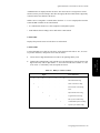
1RWLFH
This document contains proprietary information which is protected by copyright. All
Rights Reserved. Reproduction, adaptation, or translation without prior written
permission is prohibited, except as allowed under the copyright laws.
Agilent Technologies
Healthcare Solutions Group Headquarters
3000 Minuteman Road
Andover, MA 01810
1-800-934-7372
Publication number
M1205-9303L
Printed 06/2000
Warranty
The information contained in this document is subject to change without notice.
Agilent makes no warranty of any kind with regard to this material, including, but not
limited to, the implied warranties or merchantability and fitness for a particular
purpose.
Agilent shall not be liable for errors contained herein or for incidental or
consequential damages in connection with the furnishing, performance, or use of this
material.
Copyright © Agilent Technologies, Inc. 1998, 1999, 2000
3ULQWLQJ+LVWRU\
New editions of this document will incorporate all material updated since the
previous edition. Update packages may be issued between editions and contain
replacement and additional pages to be merged by a revision date at the bottom of the
page. Note that pages which are rearranged due to changes on a previous page are not
considered revised.
The documentation printing date and part number indicate its current edition. The
printing date and part number change when a new edition is printed.
First Edition ......................................... September 1998
Part Number M1205-9303K
Second Edition ..................................... April 1999
Part Number M1205-9303L
Third Edition........................................ June 2000
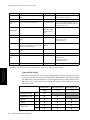
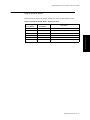
&RQWHQWV
2YHUYLHZ 2YHUYLHZ
&KDSWHU,QWURGXFLQJWKH$JLOHQW996HULHV Objective . . . . . . . . . . . . . . . . . . . . . . . . . . . . . . . . . . . . . . . . . . . . . . . . . . . . . . . . . . . . . . . . . . . . . . . . . . . 1-1
In this chapter . . . . . . . . . . . . . . . . . . . . . . . . . . . . . . . . . . . . . . . . . . . . . . . . . . . . . . . . . . . . . . . . . . . . . . . 1-1
Features . . . . . . . . . . . . . . . . . . . . . . . . . . . . . . . . . . . . . . . . . . . . . . . . . . . . . . . . . . . . . . . . . . . . . . . . . . . . . . . . 1-2
Physical, Functional Overview . . . . . . . . . . . . . . . . . . . . . . . . . . . . . . . . . . . . . . . . . . . . . . . . . . . . . . . . . . . . . . 1-4
Mainframe . . . . . . . . . . . . . . . . . . . . . . . . . . . . . . . . . . . . . . . . . . . . . . . . . . . . . . . . . . . . . . . . . . . . . . . . . . 1-4
Display . . . . . . . . . . . . . . . . . . . . . . . . . . . . . . . . . . . . . . . . . . . . . . . . . . . . . . . . . . . . . . . . . . . . . . . . . . . . 1-4
System Board . . . . . . . . . . . . . . . . . . . . . . . . . . . . . . . . . . . . . . . . . . . . . . . . . . . . . . . . . . . . . . . . . . . . . . . 1-6
Interface Connections . . . . . . . . . . . . . . . . . . . . . . . . . . . . . . . . . . . . . . . . . . . . . . . . . . . . . . . . . . . . . . . . . 1-7
Flat Panel Adapter Board . . . . . . . . . . . . . . . . . . . . . . . . . . . . . . . . . . . . . . . . . . . . . . . . . . . . . . . . . . . . . . 1-8
Power Supply . . . . . . . . . . . . . . . . . . . . . . . . . . . . . . . . . . . . . . . . . . . . . . . . . . . . . . . . . . . . . . . . . . . . . . . 1-8
Plug-in Satellite Rack . . . . . . . . . . . . . . . . . . . . . . . . . . . . . . . . . . . . . . . . . . . . . . . . . . . . . . . . . . . . . . . . 1-10
Parameter Modules . . . . . . . . . . . . . . . . . . . . . . . . . . . . . . . . . . . . . . . . . . . . . . . . . . . . . . . . . . . . . . . . . . 1-11
Front Panel . . . . . . . . . . . . . . . . . . . . . . . . . . . . . . . . . . . . . . . . . . . . . . . . . . . . . . . . . . . . . . . . . . . . . . . . 1-12
Interfaces . . . . . . . . . . . . . . . . . . . . . . . . . . . . . . . . . . . . . . . . . . . . . . . . . . . . . . . . . . . . . . . . . . . . . . . . . . 1-15
Agilent Patient Care System Interface . . . . . . . . . . . . . . . . . . . . . . . . . . . . . . . . . . . . . . . . . . . . . . . . . . . 1-16
RS-232 Network . . . . . . . . . . . . . . . . . . . . . . . . . . . . . . . . . . . . . . . . . . . . . . . . . . . . . . . . . . . . . . . . . . . . 1-16
Patient Data Management . . . . . . . . . . . . . . . . . . . . . . . . . . . . . . . . . . . . . . . . . . . . . . . . . . . . . . . . . . . . . 1-16
Specifications . . . . . . . . . . . . . . . . . . . . . . . . . . . . . . . . . . . . . . . . . . . . . . . . . . . . . . . . . . . . . . . . . . . . . . . . . . 1-17
Functionality and Option Sets . . . . . . . . . . . . . . . . . . . . . . . . . . . . . . . . . . . . . . . . . . . . . . . . . . . . . . . . . 1-17
Dimension and Weight . . . . . . . . . . . . . . . . . . . . . . . . . . . . . . . . . . . . . . . . . . . . . . . . . . . . . . . . . . . . . . . 1-17
Environmental . . . . . . . . . . . . . . . . . . . . . . . . . . . . . . . . . . . . . . . . . . . . . . . . . . . . . . . . . . . . . . . . . . . . . . 1-18
Safety . . . . . . . . . . . . . . . . . . . . . . . . . . . . . . . . . . . . . . . . . . . . . . . . . . . . . . . . . . . . . . . . . . . . . . . . . . . . 1-18
AC Input . . . . . . . . . . . . . . . . . . . . . . . . . . . . . . . . . . . . . . . . . . . . . . . . . . . . . . . . . . . . . . . . . . . . . . . . . . 1-18
Patient Data Management . . . . . . . . . . . . . . . . . . . . . . . . . . . . . . . . . . . . . . . . . . . . . . . . . . . . . . . . . . . . . 1-19
Display . . . . . . . . . . . . . . . . . . . . . . . . . . . . . . . . . . . . . . . . . . . . . . . . . . . . . . . . . . . . . . . . . . . . . . . . . . . 1-20
Parameter Modules . . . . . . . . . . . . . . . . . . . . . . . . . . . . . . . . . . . . . . . . . . . . . . . . . . . . . . . . . . . . . . . . . . 1-20
Plug-in Satellite Racks . . . . . . . . . . . . . . . . . . . . . . . . . . . . . . . . . . . . . . . . . . . . . . . . . . . . . . . . . . . . . . . 1-20
Mounting Options . . . . . . . . . . . . . . . . . . . . . . . . . . . . . . . . . . . . . . . . . . . . . . . . . . . . . . . . . . . . . . . . . . . . . . . 1-20
Practice Exercise. . . . . . . . . . . . . . . . . . . . . . . . . . . . . . . . . . . . . . . . . . . . . . . . . . . . . . . . . . . . . . . . . . . . . . . . 1-21
Practice Exercise Answers . . . . . . . . . . . . . . . . . . . . . . . . . . . . . . . . . . . . . . . . . . . . . . . . . . . . . . . . . . . . 1-23
&KDSWHU7HVWLQJ0DLQWDLQLQJWKH$JLOHQW996HULHV Objectives . . . . . . . . . . . . . . . . . . . . . . . . . . . . . . . . . . . . . . . . . . . . . . . . . . . . . . . . . . . . . . . . . . . . . . . . . . . . . . 2-1
Concepts . . . . . . . . . . . . . . . . . . . . . . . . . . . . . . . . . . . . . . . . . . . . . . . . . . . . . . . . . . . . . . . . . . . . . . . . . . . . . . . 2-1
Maintenance Checklist . . . . . . . . . . . . . . . . . . . . . . . . . . . . . . . . . . . . . . . . . . . . . . . . . . . . . . . . . . . . . . . . . . . . 2-2
Test and Inspection Requirements . . . . . . . . . . . . . . . . . . . . . . . . . . . . . . . . . . . . . . . . . . . . . . . . . . . . . . . . . . . 2-3
Power On and Performance Tests . . . . . . . . . . . . . . . . . . . . . . . . . . . . . . . . . . . . . . . . . . . . . . . . . . . . . . . . 2-5
Safety Tests . . . . . . . . . . . . . . . . . . . . . . . . . . . . . . . . . . . . . . . . . . . . . . . . . . . . . . . . . . . . . . . . . . . . . . . . 2-11
General Inspections of the System . . . . . . . . . . . . . . . . . . . . . . . . . . . . . . . . . . . . . . . . . . . . . . . . . . . . . . . . . . 2-15
Inspect the System Hardware . . . . . . . . . . . . . . . . . . . . . . . . . . . . . . . . . . . . . . . . . . . . . . . . . . . . . . . . . . 2-15
Inspect the Cables and Cords . . . . . . . . . . . . . . . . . . . . . . . . . . . . . . . . . . . . . . . . . . . . . . . . . . . . . . . . . . 2-15
Inspect the LEDs of the System . . . . . . . . . . . . . . . . . . . . . . . . . . . . . . . . . . . . . . . . . . . . . . . . . . . . . . . . 2-16
Inspect the Flat Panel Display . . . . . . . . . . . . . . . . . . . . . . . . . . . . . . . . . . . . . . . . . . . . . . . . . . . . . . . . . 2-16
Inspect the Controls of the System . . . . . . . . . . . . . . . . . . . . . . . . . . . . . . . . . . . . . . . . . . . . . . . . . . . . . . 2-17
Performance Assurance Test. . . . . . . . . . . . . . . . . . . . . . . . . . . . . . . . . . . . . . . . . . . . . . . . . . . . . . . . . . . . . . . 2-18
Replacement of Backlight Tube Assembly. . . . . . . . . . . . . . . . . . . . . . . . . . . . . . . . . . . . . . . . . . . . . . . . . . . . 2-19
Content
5
Battery Care and Handling . . . . . . . . . . . . . . . . . . . . . . . . . . . . . . . . . . . . . . . . . . . . . . . . . . . . . . . . . . . . . . . .
Cleaning and Disinfecting Procedures . . . . . . . . . . . . . . . . . . . . . . . . . . . . . . . . . . . . . . . . . . . . . . . . . . . . . . .
Objective . . . . . . . . . . . . . . . . . . . . . . . . . . . . . . . . . . . . . . . . . . . . . . . . . . . . . . . . . . . . . . . . . . . . . . . . . .
Concepts . . . . . . . . . . . . . . . . . . . . . . . . . . . . . . . . . . . . . . . . . . . . . . . . . . . . . . . . . . . . . . . . . . . . . . . . . .
General Cleaning of the System . . . . . . . . . . . . . . . . . . . . . . . . . . . . . . . . . . . . . . . . . . . . . . . . . . . . . . . .
General Disinfecting of the System . . . . . . . . . . . . . . . . . . . . . . . . . . . . . . . . . . . . . . . . . . . . . . . . . . . . .
Cleaning the Recorder Module . . . . . . . . . . . . . . . . . . . . . . . . . . . . . . . . . . . . . . . . . . . . . . . . . . . . . . . . .
Replacing Recorder Paper . . . . . . . . . . . . . . . . . . . . . . . . . . . . . . . . . . . . . . . . . . . . . . . . . . . . . . . . . . . .
Removing Paper Loaded Backwards . . . . . . . . . . . . . . . . . . . . . . . . . . . . . . . . . . . . . . . . . . . . . . . . . . . .
Cleaning the Blood Analysis Module . . . . . . . . . . . . . . . . . . . . . . . . . . . . . . . . . . . . . . . . . . . . . . . . . . . .
Upgrade and Cloning Instructions . . . . . . . . . . . . . . . . . . . . . . . . . . . . . . . . . . . . . . . . . . . . . . . . . . . . . . . . . .
Parts Checklist . . . . . . . . . . . . . . . . . . . . . . . . . . . . . . . . . . . . . . . . . . . . . . . . . . . . . . . . . . . . . . . . . . . . .
Connecting the Flash Programming Tool . . . . . . . . . . . . . . . . . . . . . . . . . . . . . . . . . . . . . . . . . . . . . . . . .
Upgrading the Utility CPU Software . . . . . . . . . . . . . . . . . . . . . . . . . . . . . . . . . . . . . . . . . . . . . . . . . . . .
Upgrading the Application CPU Software . . . . . . . . . . . . . . . . . . . . . . . . . . . . . . . . . . . . . . . . . . . . . . . .
Performing an EEPROM Upgrade . . . . . . . . . . . . . . . . . . . . . . . . . . . . . . . . . . . . . . . . . . . . . . . . . . . . . .
Performing EEPROM Cloning . . . . . . . . . . . . . . . . . . . . . . . . . . . . . . . . . . . . . . . . . . . . . . . . . . . . . . . . .
EEPROM Upgrades Between Application Bundles . . . . . . . . . . . . . . . . . . . . . . . . . . . . . . . . . . . . . . . . .
2-19
2-23
2-23
2-23
2-24
2-25
2-26
2-27
2-29
2-30
2-31
2-31
2-34
2-36
2-39
2-41
2-50
2-52
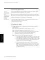
&KDSWHU7URXEOHVKRRWLQJWKH$JLOHQW996HULHV Objective . . . . . . . . . . . . . . . . . . . . . . . . . . . . . . . . . . . . . . . . . . . . . . . . . . . . . . . . . . . . . . . . . . . . . . . . . . . 3-1
In this chapter . . . . . . . . . . . . . . . . . . . . . . . . . . . . . . . . . . . . . . . . . . . . . . . . . . . . . . . . . . . . . . . . . . . . . . . 3-1
Isolating and Solving Instrument Problems . . . . . . . . . . . . . . . . . . . . . . . . . . . . . . . . . . . . . . . . . . . . . . . . . . . . 3-2
Troubleshooting Checklists . . . . . . . . . . . . . . . . . . . . . . . . . . . . . . . . . . . . . . . . . . . . . . . . . . . . . . . . . . . . . . . . 3-5
Check for Obvious Problems . . . . . . . . . . . . . . . . . . . . . . . . . . . . . . . . . . . . . . . . . . . . . . . . . . . . . . . . . . . 3-5
Checks before opening the instrument . . . . . . . . . . . . . . . . . . . . . . . . . . . . . . . . . . . . . . . . . . . . . . . . . . . . 3-5
Isolating problems to the correct subassembly . . . . . . . . . . . . . . . . . . . . . . . . . . . . . . . . . . . . . . . . . . . . . . 3-8
Monochrome Flat Panel . . . . . . . . . . . . . . . . . . . . . . . . . . . . . . . . . . . . . . . . . . . . . . . . . . . . . . . . . . . . . . 3-10
Color Flat Panel . . . . . . . . . . . . . . . . . . . . . . . . . . . . . . . . . . . . . . . . . . . . . . . . . . . . . . . . . . . . . . . . . . . . 3-11
Blown Fuses (Model V24CT/V26CT) . . . . . . . . . . . . . . . . . . . . . . . . . . . . . . . . . . . . . . . . . . . . . . . . . . . 3-11
Parameter Rack/Module Fault (Model V24CT/V26CT) . . . . . . . . . . . . . . . . . . . . . . . . . . . . . . . . . . . . . 3-14
Battery Problems . . . . . . . . . . . . . . . . . . . . . . . . . . . . . . . . . . . . . . . . . . . . . . . . . . . . . . . . . . . . . . . . . . . 3-14
&KDSWHU8VLQJ6XSSRUW )XQFWLRQV Objective . . . . . . . . . . . . . . . . . . . . . . . . . . . . . . . . . . . . . . . . . . . . . . . . . . . . . . . . . . . . . . . . . . . . . . . . . . . 4-1
In this chapter . . . . . . . . . . . . . . . . . . . . . . . . . . . . . . . . . . . . . . . . . . . . . . . . . . . . . . . . . . . . . . . . . . . . . . . 4-1
Using Support Functions . . . . . . . . . . . . . . . . . . . . . . . . . . . . . . . . . . . . . . . . . . . . . . . . . . . . . . . . . . . . . . . . . . 4-2
Error Codes . . . . . . . . . . . . . . . . . . . . . . . . . . . . . . . . . . . . . . . . . . . . . . . . . . . . . . . . . . . . . . . . . . . . . . . . . 4-2
System Configuration Problems . . . . . . . . . . . . . . . . . . . . . . . . . . . . . . . . . . . . . . . . . . . . . . . . . . . . . . . . . 4-8
System Hardware/Software Problem/RAM Problem . . . . . . . . . . . . . . . . . . . . . . . . . . . . . . . . . . . . . . . . . 4-8
General Error Code List . . . . . . . . . . . . . . . . . . . . . . . . . . . . . . . . . . . . . . . . . . . . . . . . . . . . . . . . . . . . . . . 4-9
Error Code List for Specific Device IDs Other Than 16400 (4010H) . . . . . . . . . . . . . . . . . . . . . . . . . . . 4-10
Using the Service Mode . . . . . . . . . . . . . . . . . . . . . . . . . . . . . . . . . . . . . . . . . . . . . . . . . . . . . . . . . . . . . . . . . . 4-11
Accessing Service Mode . . . . . . . . . . . . . . . . . . . . . . . . . . . . . . . . . . . . . . . . . . . . . . . . . . . . . . . . . . . . . . 4-11
Facilities Available in the Service Mode . . . . . . . . . . . . . . . . . . . . . . . . . . . . . . . . . . . . . . . . . . . . . . . . . 4-11
Changing the Global Switches . . . . . . . . . . . . . . . . . . . . . . . . . . . . . . . . . . . . . . . . . . . . . . . . . . . . . . . . . 4-12
Setting the Date and Time . . . . . . . . . . . . . . . . . . . . . . . . . . . . . . . . . . . . . . . . . . . . . . . . . . . . . . . . . . . . 4-13
Displaying the Status Log . . . . . . . . . . . . . . . . . . . . . . . . . . . . . . . . . . . . . . . . . . . . . . . . . . . . . . . . . . . . . 4-13
To Access Monitor Revisions Screen . . . . . . . . . . . . . . . . . . . . . . . . . . . . . . . . . . . . . . . . . . . . . . . . . . . . 4-14
Summary of the Power On Modes . . . . . . . . . . . . . . . . . . . . . . . . . . . . . . . . . . . . . . . . . . . . . . . . . . . . . . 4-15
Network Test . . . . . . . . . . . . . . . . . . . . . . . . . . . . . . . . . . . . . . . . . . . . . . . . . . . . . . . . . . . . . . . . . . . . . . 4-17
6
Contents
Performing the RS232 Loopback Test . . . . . . . . . . . . . . . . . . . . . . . . . . . . . . . . . . . . . . . . . . . . . . . . . . .
Display Tests . . . . . . . . . . . . . . . . . . . . . . . . . . . . . . . . . . . . . . . . . . . . . . . . . . . . . . . . . . . . . . . . . . . . . .
Description of the Boot Process . . . . . . . . . . . . . . . . . . . . . . . . . . . . . . . . . . . . . . . . . . . . . . . . . . . . . . . . . . . .
Overview . . . . . . . . . . . . . . . . . . . . . . . . . . . . . . . . . . . . . . . . . . . . . . . . . . . . . . . . . . . . . . . . . . . . . . . . . .
Fixing Recorder Problems . . . . . . . . . . . . . . . . . . . . . . . . . . . . . . . . . . . . . . . . . . . . . . . . . . . . . . . . . . . . . . . .
Fixing Printing Problems . . . . . . . . . . . . . . . . . . . . . . . . . . . . . . . . . . . . . . . . . . . . . . . . . . . . . . . . . . . . . . . . .
Local “Jet” Printer Configurations . . . . . . . . . . . . . . . . . . . . . . . . . . . . . . . . . . . . . . . . . . . . . . . . . . . . . .
HP LaserJet/LaserJet+ Printers . . . . . . . . . . . . . . . . . . . . . . . . . . . . . . . . . . . . . . . . . . . . . . . . . . . . . . . . .
HP LaserJet II/III/IV Series Printers . . . . . . . . . . . . . . . . . . . . . . . . . . . . . . . . . . . . . . . . . . . . . . . . . . . . .
HP 2673A Printer . . . . . . . . . . . . . . . . . . . . . . . . . . . . . . . . . . . . . . . . . . . . . . . . . . . . . . . . . . . . . . . . . . .
4-21
4-23
4-24
4-24
4-26
4-27
4-27
4-28
4-28
4-28
&KDSWHU7URXEOHVKRRWLQJ3OXJLQ0RGXOHV Objectives . . . . . . . . . . . . . . . . . . . . . . . . . . . . . . . . . . . . . . . . . . . . . . . . . . . . . . . . . . . . . . . . . . . . . . . . . . 5-1
Concepts . . . . . . . . . . . . . . . . . . . . . . . . . . . . . . . . . . . . . . . . . . . . . . . . . . . . . . . . . . . . . . . . . . . . . . . . . . . 5-1
Procedure Overview . . . . . . . . . . . . . . . . . . . . . . . . . . . . . . . . . . . . . . . . . . . . . . . . . . . . . . . . . . . . . . . . . . . . . . 5-2
Troubleshooting tcpO2/tcpCO2 Problems. . . . . . . . . . . . . . . . . . . . . . . . . . . . . . . . . . . . . . . . . . . . . . . . . . . . . . 5-3
To Troubleshoot the Module . . . . . . . . . . . . . . . . . . . . . . . . . . . . . . . . . . . . . . . . . . . . . . . . . . . . . . . . . . . 5-3
Test Equipment . . . . . . . . . . . . . . . . . . . . . . . . . . . . . . . . . . . . . . . . . . . . . . . . . . . . . . . . . . . . . . . . . . . . . . 5-6
Procedure . . . . . . . . . . . . . . . . . . . . . . . . . . . . . . . . . . . . . . . . . . . . . . . . . . . . . . . . . . . . . . . . . . . . . . . . . . 5-6
Troubleshooting ECG and ECG/RESP Problems . . . . . . . . . . . . . . . . . . . . . . . . . . . . . . . . . . . . . . . . . . . . . . . 5-8
To Troubleshoot the Module . . . . . . . . . . . . . . . . . . . . . . . . . . . . . . . . . . . . . . . . . . . . . . . . . . . . . . . . . . . 5-8
Troubleshooting Pressure Problems . . . . . . . . . . . . . . . . . . . . . . . . . . . . . . . . . . . . . . . . . . . . . . . . . . . . . . . . . 5-10
To Troubleshoot the Module . . . . . . . . . . . . . . . . . . . . . . . . . . . . . . . . . . . . . . . . . . . . . . . . . . . . . . . . . . 5-10
Troubleshooting NBP Problems . . . . . . . . . . . . . . . . . . . . . . . . . . . . . . . . . . . . . . . . . . . . . . . . . . . . . . . . . . . . 5-12
To Troubleshoot the Module . . . . . . . . . . . . . . . . . . . . . . . . . . . . . . . . . . . . . . . . . . . . . . . . . . . . . . . . . . 5-12
Troubleshooting Cardiac Output Problems . . . . . . . . . . . . . . . . . . . . . . . . . . . . . . . . . . . . . . . . . . . . . . . . . . . 5-14
To Troubleshoot the Module . . . . . . . . . . . . . . . . . . . . . . . . . . . . . . . . . . . . . . . . . . . . . . . . . . . . . . . . . . 5-14
Troubleshooting SpO2/Pleth Problems . . . . . . . . . . . . . . . . . . . . . . . . . . . . . . . . . . . . . . . . . . . . . . . . . . . . . . . 5-17
To Troubleshoot the Module . . . . . . . . . . . . . . . . . . . . . . . . . . . . . . . . . . . . . . . . . . . . . . . . . . . . . . . . . . 5-17
Troubleshooting Temperature Module Problems . . . . . . . . . . . . . . . . . . . . . . . . . . . . . . . . . . . . . . . . . . . . . . . 5-19
To Troubleshoot the Module . . . . . . . . . . . . . . . . . . . . . . . . . . . . . . . . . . . . . . . . . . . . . . . . . . . . . . . . . . 5-19
Troubleshooting CO2 Problems . . . . . . . . . . . . . . . . . . . . . . . . . . . . . . . . . . . . . . . . . . . . . . . . . . . . . . . . . . . . 5-21
To Troubleshoot the Module . . . . . . . . . . . . . . . . . . . . . . . . . . . . . . . . . . . . . . . . . . . . . . . . . . . . . . . . . . 5-21
Troubleshooting Blood Analysis Problems . . . . . . . . . . . . . . . . . . . . . . . . . . . . . . . . . . . . . . . . . . . . . . . . . . . 5-24
To Troubleshoot the Module . . . . . . . . . . . . . . . . . . . . . . . . . . . . . . . . . . . . . . . . . . . . . . . . . . . . . . . . . . 5-24
Troubleshooting BIS Problems. . . . . . . . . . . . . . . . . . . . . . . . . . . . . . . . . . . . . . . . . . . . . . . . . . . . . . . . . . . . . 5-29
To Troubleshoot the Module . . . . . . . . . . . . . . . . . . . . . . . . . . . . . . . . . . . . . . . . . . . . . . . . . . . . . . . . . . 5-29
Self-Test Procedures for BIS components . . . . . . . . . . . . . . . . . . . . . . . . . . . . . . . . . . . . . . . . . . . . . . . . 5-34
Additional information available in the Service Mode Task Window . . . . . . . . . . . . . . . . . . . . . . . . . . . 5-35
Compatibility Matrix . . . . . . . . . . . . . . . . . . . . . . . . . . . . . . . . . . . . . . . . . . . . . . . . . . . . . . . . . . . . . . . . 5-36
Troubleshooting VueLink Module Problems . . . . . . . . . . . . . . . . . . . . . . . . . . . . . . . . . . . . . . . . . . . . . . . . . . 5-37
M1032A VueLink Tests using VueLink Test Module . . . . . . . . . . . . . . . . . . . . . . . . . . . . . . . . . . . . . . . 5-37
Performing Plug-In Module Self-Tests. . . . . . . . . . . . . . . . . . . . . . . . . . . . . . . . . . . . . . . . . . . . . . . . . . . . . . . 5-39
Objective . . . . . . . . . . . . . . . . . . . . . . . . . . . . . . . . . . . . . . . . . . . . . . . . . . . . . . . . . . . . . . . . . . . . . . . . . . 5-39
Concepts . . . . . . . . . . . . . . . . . . . . . . . . . . . . . . . . . . . . . . . . . . . . . . . . . . . . . . . . . . . . . . . . . . . . . . . . . . 5-39
Performing a Quick System Check . . . . . . . . . . . . . . . . . . . . . . . . . . . . . . . . . . . . . . . . . . . . . . . . . . . . . . 5-39
Self-Test Procedure Overview . . . . . . . . . . . . . . . . . . . . . . . . . . . . . . . . . . . . . . . . . . . . . . . . . . . . . . . . . 5-40
Performing the ECG or ECG/RESP Module Self-Test . . . . . . . . . . . . . . . . . . . . . . . . . . . . . . . . . . . . . . 5-42
Performing the M1006A/B Pressure Module Self-Test . . . . . . . . . . . . . . . . . . . . . . . . . . . . . . . . . . . . . . 5-42
Performing the NBP ModuleSelf-Test . . . . . . . . . . . . . . . . . . . . . . . . . . . . . . . . . . . . . . . . . . . . . . . . . . 5-43
Performing the SpO2/Pleth Module Self-Test . . . . . . . . . . . . . . . . . . . . . . . . . . . . . . . . . . . . . . . . . . . . . 5-43
Performing the Cardiac Output Module Self-Test . . . . . . . . . . . . . . . . . . . . . . . . . . . . . . . . . . . . . . . . . . 5-43
Performing the tcpO2/tcpCO2 Module Self-Test . . . . . . . . . . . . . . . . . . . . . . . . . . . . . . . . . . . . . . . . . . . 5-44
Contents
7
Performing the CO2 Module Self-Test . . . . . . . . . . . . . . . . . . . . . . . . . . . . . . . . . . . . . . . . . . . . . . . . . . .
Performing the Temperature Module Self-Test . . . . . . . . . . . . . . . . . . . . . . . . . . . . . . . . . . . . . . . . . . . .
Performing the Blood Analysis Module Self-Test . . . . . . . . . . . . . . . . . . . . . . . . . . . . . . . . . . . . . . . . . .
Performing the Recorder Module Self-Test . . . . . . . . . . . . . . . . . . . . . . . . . . . . . . . . . . . . . . . . . . . . . . .
Performing the VueLink Module Self-Test . . . . . . . . . . . . . . . . . . . . . . . . . . . . . . . . . . . . . . . . . . . . . . .
5-44
5-45
5-45
5-45
5-46
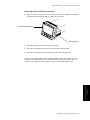
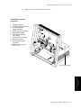
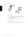
&KDSWHU5HSDLULQJWKH$JLOHQW0RGHO9 Objective . . . . . . . . . . . . . . . . . . . . . . . . . . . . . . . . . . . . . . . . . . . . . . . . . . . . . . . . . . . . . . . . . . . . . . . . . . . 6-1
In this chapter . . . . . . . . . . . . . . . . . . . . . . . . . . . . . . . . . . . . . . . . . . . . . . . . . . . . . . . . . . . . . . . . . . . . . . . 6-1
Removal Procedures . . . . . . . . . . . . . . . . . . . . . . . . . . . . . . . . . . . . . . . . . . . . . . . . . . . . . . . . . . . . . . . . . . . . . . 6-2
Tools Required: . . . . . . . . . . . . . . . . . . . . . . . . . . . . . . . . . . . . . . . . . . . . . . . . . . . . . . . . . . . . . . . . . . . . . 6-2
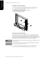
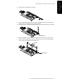
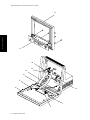
Removing the Front Housing Assembly . . . . . . . . . . . . . . . . . . . . . . . . . . . . . . . . . . . . . . . . . . . . . . . . . . 6-3
Removing the Flat Panel Display Assembly . . . . . . . . . . . . . . . . . . . . . . . . . . . . . . . . . . . . . . . . . . . . . . . 6-5
Removing the Front Housing Keypad . . . . . . . . . . . . . . . . . . . . . . . . . . . . . . . . . . . . . . . . . . . . . . . . . . . . 6-6
Removing the Flat Panel Adapter Board . . . . . . . . . . . . . . . . . . . . . . . . . . . . . . . . . . . . . . . . . . . . . . . . . . 6-7
Removing the Flat Panel Backlight Tube . . . . . . . . . . . . . . . . . . . . . . . . . . . . . . . . . . . . . . . . . . . . . . . . . . 6-8
Removing the System Board . . . . . . . . . . . . . . . . . . . . . . . . . . . . . . . . . . . . . . . . . . . . . . . . . . . . . . . . . . 6-10
Removing the Power Supply Assembly . . . . . . . . . . . . . . . . . . . . . . . . . . . . . . . . . . . . . . . . . . . . . . . . . . 6-12
Reassembly Procedures . . . . . . . . . . . . . . . . . . . . . . . . . . . . . . . . . . . . . . . . . . . . . . . . . . . . . . . . . . . . . . . . . . 6-16
Replacing the Front Housing Assembly . . . . . . . . . . . . . . . . . . . . . . . . . . . . . . . . . . . . . . . . . . . . . . . . . . 6-16
Replacing the Flat Panel Display Assembly . . . . . . . . . . . . . . . . . . . . . . . . . . . . . . . . . . . . . . . . . . . . . . . 6-18
Replacing the Front Housing Keypad . . . . . . . . . . . . . . . . . . . . . . . . . . . . . . . . . . . . . . . . . . . . . . . . . . . . 6-19
Replacing the Flat Panel Adapter Board . . . . . . . . . . . . . . . . . . . . . . . . . . . . . . . . . . . . . . . . . . . . . . . . . 6-20
Replacing the Flat Panel Backlight Tube . . . . . . . . . . . . . . . . . . . . . . . . . . . . . . . . . . . . . . . . . . . . . . . . . 6-21
Replacing the Power Supply Assembly . . . . . . . . . . . . . . . . . . . . . . . . . . . . . . . . . . . . . . . . . . . . . . . . . . 6-23
Replacing the System Board . . . . . . . . . . . . . . . . . . . . . . . . . . . . . . . . . . . . . . . . . . . . . . . . . . . . . . . . . . . 6-26
Practice Exercise. . . . . . . . . . . . . . . . . . . . . . . . . . . . . . . . . . . . . . . . . . . . . . . . . . . . . . . . . . . . . . . . . . . . . . . . 6-28
Practice Exercise Answers . . . . . . . . . . . . . . . . . . . . . . . . . . . . . . . . . . . . . . . . . . . . . . . . . . . . . . . . . . . . 6-29
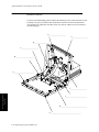
&KDSWHU5HSDLULQJWKH$JLOHQW0RGHO9&9& Objective . . . . . . . . . . . . . . . . . . . . . . . . . . . . . . . . . . . . . . . . . . . . . . . . . . . . . . . . . . . . . . . . . . . . . . . . . . . 7-1
In this chapter . . . . . . . . . . . . . . . . . . . . . . . . . . . . . . . . . . . . . . . . . . . . . . . . . . . . . . . . . . . . . . . . . . . . . . . 7-1
Removal Procedures . . . . . . . . . . . . . . . . . . . . . . . . . . . . . . . . . . . . . . . . . . . . . . . . . . . . . . . . . . . . . . . . . . . . . . 7-3
Removing the Front Housing . . . . . . . . . . . . . . . . . . . . . . . . . . . . . . . . . . . . . . . . . . . . . . . . . . . . . . . . . . . . . . . 7-5
Removing the Rear Housing. . . . . . . . . . . . . . . . . . . . . . . . . . . . . . . . . . . . . . . . . . . . . . . . . . . . . . . . . . . . . . . . 7-5
Removing the System Board . . . . . . . . . . . . . . . . . . . . . . . . . . . . . . . . . . . . . . . . . . . . . . . . . . . . . . . . . . . 7-5
Removing the Power Supply Assembly . . . . . . . . . . . . . . . . . . . . . . . . . . . . . . . . . . . . . . . . . . . . . . . . . . . 7-8
Replacement Procedures. . . . . . . . . . . . . . . . . . . . . . . . . . . . . . . . . . . . . . . . . . . . . . . . . . . . . . . . . . . . . . . . . . 7-12
Rear Housing Replacement . . . . . . . . . . . . . . . . . . . . . . . . . . . . . . . . . . . . . . . . . . . . . . . . . . . . . . . . . . . . . . . 7-13
Replacing the Power Supply Board . . . . . . . . . . . . . . . . . . . . . . . . . . . . . . . . . . . . . . . . . . . . . . . . . . . . . 7-13
Replacing the System Board . . . . . . . . . . . . . . . . . . . . . . . . . . . . . . . . . . . . . . . . . . . . . . . . . . . . . . . . . . . 7-16
&KDSWHU5HSDLULQJWKH$JLOHQW0RGHO9&79&7 Objective . . . . . . . . . . . . . . . . . . . . . . . . . . . . . . . . . . . . . . . . . . . . . . . . . . . . . . . . . . . . . . . . . . . . . . . . . . .
In this chapter . . . . . . . . . . . . . . . . . . . . . . . . . . . . . . . . . . . . . . . . . . . . . . . . . . . . . . . . . . . . . . . . . . . . . . .
Overview Removal Procedures . . . . . . . . . . . . . . . . . . . . . . . . . . . . . . . . . . . . . . . . . . . . . . . . . . . . . . . . . . . . .
Front Housing Removal Procedures . . . . . . . . . . . . . . . . . . . . . . . . . . . . . . . . . . . . . . . . . . . . . . . . . . . . . . . . . .
Removing the Lead Acid Batteries . . . . . . . . . . . . . . . . . . . . . . . . . . . . . . . . . . . . . . . . . . . . . . . . . . . . . . .
Removing the Parameter Module Rack . . . . . . . . . . . . . . . . . . . . . . . . . . . . . . . . . . . . . . . . . . . . . . . . . . .
Front Housing Removal Procedures . . . . . . . . . . . . . . . . . . . . . . . . . . . . . . . . . . . . . . . . . . . . . . . . . . . . . . . . . .
8
8-1
8-1
8-3
8-4
8-5
8-6
8-6
Contents
Rear Housing Removal Procedures . . . . . . . . . . . . . . . . . . . . . . . . . . . . . . . . . . . . . . . . . . . . . . . . . . . . . . . . . . 8-7
Removing Battery Contact Board . . . . . . . . . . . . . . . . . . . . . . . . . . . . . . . . . . . . . . . . . . . . . . . . . . . . . . . . 8-7
Removing the System Board . . . . . . . . . . . . . . . . . . . . . . . . . . . . . . . . . . . . . . . . . . . . . . . . . . . . . . . . . . . 8-8
Removing the Power Supply Assembly . . . . . . . . . . . . . . . . . . . . . . . . . . . . . . . . . . . . . . . . . . . . . . . . . . 8-10
Removing Parameter Module Rack Docking Connector . . . . . . . . . . . . . . . . . . . . . . . . . . . . . . . . . . . . . 8-13
Rear Housing Replacement Procedures . . . . . . . . . . . . . . . . . . . . . . . . . . . . . . . . . . . . . . . . . . . . . . . . . . . . . . 8-15
Replacing Parameter Module Rack Connector . . . . . . . . . . . . . . . . . . . . . . . . . . . . . . . . . . . . . . . . . . . . . 8-15
Replacing Power Supply Assembly . . . . . . . . . . . . . . . . . . . . . . . . . . . . . . . . . . . . . . . . . . . . . . . . . . . . . 8-15
Replacing System Board . . . . . . . . . . . . . . . . . . . . . . . . . . . . . . . . . . . . . . . . . . . . . . . . . . . . . . . . . . . . . . 8-17
Replacing Battery Contact Board . . . . . . . . . . . . . . . . . . . . . . . . . . . . . . . . . . . . . . . . . . . . . . . . . . . . . . 8-18
Replacing Lead-Acid Batteries . . . . . . . . . . . . . . . . . . . . . . . . . . . . . . . . . . . . . . . . . . . . . . . . . . . . . . . . . 8-18
Practice Exercise. . . . . . . . . . . . . . . . . . . . . . . . . . . . . . . . . . . . . . . . . . . . . . . . . . . . . . . . . . . . . . . . . . . . . . . . 8-19
Practice Exercise Answers . . . . . . . . . . . . . . . . . . . . . . . . . . . . . . . . . . . . . . . . . . . . . . . . . . . . . . . . . . . . 8-20
&KDSWHU)URQW+RXVLQJ$VVHPEO\9&9&9&79&7 Objective . . . . . . . . . . . . . . . . . . . . . . . . . . . . . . . . . . . . . . . . . . . . . . . . . . . . . . . . . . . . . . . . . . . . . . . . . . . 9-1
In this chapter . . . . . . . . . . . . . . . . . . . . . . . . . . . . . . . . . . . . . . . . . . . . . . . . . . . . . . . . . . . . . . . . . . . . . . . 9-1
Removing the Front Housing Assembly. . . . . . . . . . . . . . . . . . . . . . . . . . . . . . . . . . . . . . . . . . . . . . . . . . . . . . . 9-2
To remove the front housing assembly: . . . . . . . . . . . . . . . . . . . . . . . . . . . . . . . . . . . . . . . . . . . . . . . . . . . 9-2
Version 1: Assembly procedure for Display Options 021 to 025
and J90 with PDC 3931 or greater . . . . . . . . . . . . . . . . . . . . . . . . . . . . . . . . . . . . . . . . . . . . . . . . . . . . . . . . . . . 9-5
Removing the Board Shield . . . . . . . . . . . . . . . . . . . . . . . . . . . . . . . . . . . . . . . . . . . . . . . . . . . . . . . . . . . . 9-5
Removing the Flat Panel Display Assembly . . . . . . . . . . . . . . . . . . . . . . . . . . . . . . . . . . . . . . . . . . . . . . . 9-6
Removing the 3-Board Assembly . . . . . . . . . . . . . . . . . . . . . . . . . . . . . . . . . . . . . . . . . . . . . . . . . . . . . . . . 9-8
Removing the Flat Panel . . . . . . . . . . . . . . . . . . . . . . . . . . . . . . . . . . . . . . . . . . . . . . . . . . . . . . . . . . . . . . 9-10
Removing the Flat Panel Backlight Tube . . . . . . . . . . . . . . . . . . . . . . . . . . . . . . . . . . . . . . . . . . . . . . . . . 9-11
Remove the Front Housing Keypad . . . . . . . . . . . . . . . . . . . . . . . . . . . . . . . . . . . . . . . . . . . . . . . . . . . . . 9-12
Version 2: Assembly Procedure for Display Options 026 to 029
less than PDC 3927. . . . . . . . . . . . . . . . . . . . . . . . . . . . . . . . . . . . . . . . . . . . . . . . . . . . . . . . . . . . . . . . . . . . . . 9-13
Removing the Board Shield . . . . . . . . . . . . . . . . . . . . . . . . . . . . . . . . . . . . . . . . . . . . . . . . . . . . . . . . . . . 9-13
Removing the Flat Panel Display Assembly . . . . . . . . . . . . . . . . . . . . . . . . . . . . . . . . . . . . . . . . . . . . . . 9-14
Removing the 3-Board Assembly . . . . . . . . . . . . . . . . . . . . . . . . . . . . . . . . . . . . . . . . . . . . . . . . . . . . . . . 9-14
Removing the Flat Panel . . . . . . . . . . . . . . . . . . . . . . . . . . . . . . . . . . . . . . . . . . . . . . . . . . . . . . . . . . . . . . 9-16
Removing the Flat Panel Backlight Tube . . . . . . . . . . . . . . . . . . . . . . . . . . . . . . . . . . . . . . . . . . . . . . . . . 9-17
Now continue the disassembly procedure on page 9-18 . . . . . . . . . . . . . . . . . . . . . . . . . . . . . . . . . . . . . 9-17
Remove the Front Housing Keypad . . . . . . . . . . . . . . . . . . . . . . . . . . . . . . . . . . . . . . . . . . . . . . . . . . . . . 9-18
Version 3&4: Assembly Procedure for Display Options 027 and
028 with PDC 3927 and above . . . . . . . . . . . . . . . . . . . . . . . . . . . . . . . . . . . . . . . . . . . . . . . . . . . . . . . . . . . . . 9-19
Removing the Flat Panel Display Assembly . . . . . . . . . . . . . . . . . . . . . . . . . . . . . . . . . . . . . . . . . . . . . . 9-20
Removing the Display Driver Board and Converter Assemblies . . . . . . . . . . . . . . . . . . . . . . . . . . . . . . . 9-21
Removing the Flat Panel . . . . . . . . . . . . . . . . . . . . . . . . . . . . . . . . . . . . . . . . . . . . . . . . . . . . . . . . . . . . . . 9-21
Removing the Flat Panel Backlight Tube . . . . . . . . . . . . . . . . . . . . . . . . . . . . . . . . . . . . . . . . . . . . . . . . . 9-23
Remove the Front Housing Keypad . . . . . . . . . . . . . . . . . . . . . . . . . . . . . . . . . . . . . . . . . . . . . . . . . . . . . 9-24
Front Housing Replacement Procedures. . . . . . . . . . . . . . . . . . . . . . . . . . . . . . . . . . . . . . . . . . . . . . . . . . . . . . 9-25
Replacing Front Housing Keypad . . . . . . . . . . . . . . . . . . . . . . . . . . . . . . . . . . . . . . . . . . . . . . . . . . . . . . 9-26
Replacing the Flat Panel Backlight . . . . . . . . . . . . . . . . . . . . . . . . . . . . . . . . . . . . . . . . . . . . . . . . . . . . . . 9-26
Replacing the Flat Panel . . . . . . . . . . . . . . . . . . . . . . . . . . . . . . . . . . . . . . . . . . . . . . . . . . . . . . . . . . . . . . 9-28
Replacing the 3-Board Assembly . . . . . . . . . . . . . . . . . . . . . . . . . . . . . . . . . . . . . . . . . . . . . . . . . . . . . . . 9-29
Replacing the Flat Panel Display Assembly . . . . . . . . . . . . . . . . . . . . . . . . . . . . . . . . . . . . . . . . . . . . . . . 9-31
Replacing the Front Housing Assembly . . . . . . . . . . . . . . . . . . . . . . . . . . . . . . . . . . . . . . . . . . . . . . . . . . 9-32
Replacing the Board Shield . . . . . . . . . . . . . . . . . . . . . . . . . . . . . . . . . . . . . . . . . . . . . . . . . . . . . . . . . . . 9-34
Replacing Parameter Module Rack Assembly (M1276-60001) . . . . . . . . . . . . . . . . . . . . . . . . . . . . . . . . 9-34
Replacing Lead-Acid Batteries (CT model) . . . . . . . . . . . . . . . . . . . . . . . . . . . . . . . . . . . . . . . . . . . . . . . 9-34
Contents
9
Practice Exercise. . . . . . . . . . . . . . . . . . . . . . . . . . . . . . . . . . . . . . . . . . . . . . . . . . . . . . . . . . . . . . . . . . . . . . . . 9-35
Practice Exercise Answers . . . . . . . . . . . . . . . . . . . . . . . . . . . . . . . . . . . . . . . . . . . . . . . . . . . . . . . . . . . . 9-36
&KDSWHU5HPRYLQJ5HSODFLQJ3OXJLQ0RGXOHV Objective . . . . . . . . . . . . . . . . . . . . . . . . . . . . . . . . . . . . . . . . . . . . . . . . . . . . . . . . . . . . . . . . . . . . . . . . . .
In this chapter . . . . . . . . . . . . . . . . . . . . . . . . . . . . . . . . . . . . . . . . . . . . . . . . . . . . . . . . . . . . . . . . . . . . . .
Replaceable Parts for Plug-in Modules . . . . . . . . . . . . . . . . . . . . . . . . . . . . . . . . . . . . . . . . . . . . . . . . . .
Snap Lock . . . . . . . . . . . . . . . . . . . . . . . . . . . . . . . . . . . . . . . . . . . . . . . . . . . . . . . . . . . . . . . . . . . . . . . . .
Plug-In Module Removal . . . . . . . . . . . . . . . . . . . . . . . . . . . . . . . . . . . . . . . . . . . . . . . . . . . . . . . . . . . . .
NBP Inlet Connector Insert . . . . . . . . . . . . . . . . . . . . . . . . . . . . . . . . . . . . . . . . . . . . . . . . . . . . . . . . . . .
NBP Pump . . . . . . . . . . . . . . . . . . . . . . . . . . . . . . . . . . . . . . . . . . . . . . . . . . . . . . . . . . . . . . . . . . . . . . . .
tcpO2/tcpCO2 Calibration Chamber Kit . . . . . . . . . . . . . . . . . . . . . . . . . . . . . . . . . . . . . . . . . . . . . . . . . .
Recorder Module Paper . . . . . . . . . . . . . . . . . . . . . . . . . . . . . . . . . . . . . . . . . . . . . . . . . . . . . . . . . . . . . .
10-1
10-1
10-1
10-2
10-3
10-5
10-6
10-7
10-8
&KDSWHU5HSODFHPHQW3DUWV Objective . . . . . . . . . . . . . . . . . . . . . . . . . . . . . . . . . . . . . . . . . . . . . . . . . . . . . . . . . . . . . . . . . . . . . . . . . . 11-1
In this chapter . . . . . . . . . . . . . . . . . . . . . . . . . . . . . . . . . . . . . . . . . . . . . . . . . . . . . . . . . . . . . . . . . . . . . . 11-1
Product Identification . . . . . . . . . . . . . . . . . . . . . . . . . . . . . . . . . . . . . . . . . . . . . . . . . . . . . . . . . . . . . . . . . . . . 11-3
Model V24 Field Replaceable Parts . . . . . . . . . . . . . . . . . . . . . . . . . . . . . . . . . . . . . . . . . . . . . . . . . . . . . . . . . 11-4
(Monochrome Mainframe) . . . . . . . . . . . . . . . . . . . . . . . . . . . . . . . . . . . . . . . . . . . . . . . . . . . . . . . . . . . . . . . . 11-4
Model V24C/V26C Field Replaceable Parts . . . . . . . . . . . . . . . . . . . . . . . . . . . . . . . . . . . . . . . . . . . . . . . . . . 11-9
(Color Mainframe) . . . . . . . . . . . . . . . . . . . . . . . . . . . . . . . . . . . . . . . . . . . . . . . . . . . . . . . . . . . . . . . . . . . . . . 11-9
Model V24CT/V26CT Field Replaceable Parts . . . . . . . . . . . . . . . . . . . . . . . . . . . . . . . . . . . . . . . . . . . . . . . 11-16
(Color Battery Mainframe) . . . . . . . . . . . . . . . . . . . . . . . . . . . . . . . . . . . . . . . . . . . . . . . . . . . . . . . . . . . . . . . 11-16
Plug-In Modules . . . . . . . . . . . . . . . . . . . . . . . . . . . . . . . . . . . . . . . . . . . . . . . . . . . . . . . . . . . . . . . . . . . . . . . 11-23
Plug-in Module Racks . . . . . . . . . . . . . . . . . . . . . . . . . . . . . . . . . . . . . . . . . . . . . . . . . . . . . . . . . . . . . . . . . . 11-29
Patient Connectors and Accessories . . . . . . . . . . . . . . . . . . . . . . . . . . . . . . . . . . . . . . . . . . . . . . . . . . . . . . . . 11-30
General . . . . . . . . . . . . . . . . . . . . . . . . . . . . . . . . . . . . . . . . . . . . . . . . . . . . . . . . . . . . . . . . . . . . . . . . . . 11-30
ECG & ECG/Respiration Module Accessories . . . . . . . . . . . . . . . . . . . . . . . . . . . . . . . . . . . . . . . . . . . 11-30
Pressure Module Accessories . . . . . . . . . . . . . . . . . . . . . . . . . . . . . . . . . . . . . . . . . . . . . . . . . . . . . . . . . 11-33
Non-Invasive Pressure Module Accessories . . . . . . . . . . . . . . . . . . . . . . . . . . . . . . . . . . . . . . . . . . . . . 11-34
Cardiac Output Module Accessories . . . . . . . . . . . . . . . . . . . . . . . . . . . . . . . . . . . . . . . . . . . . . . . . . . . 11-36
CO2 Module Accessories . . . . . . . . . . . . . . . . . . . . . . . . . . . . . . . . . . . . . . . . . . . . . . . . . . . . . . . . . . . . 11-37
Sidestream CO2 Module Accessories . . . . . . . . . . . . . . . . . . . . . . . . . . . . . . . . . . . . . . . . . . . . . . . . . . 11-38
SpO2 Module Accessories . . . . . . . . . . . . . . . . . . . . . . . . . . . . . . . . . . . . . . . . . . . . . . . . . . . . . . . . . . . 11-38
Temperature Module Accessories . . . . . . . . . . . . . . . . . . . . . . . . . . . . . . . . . . . . . . . . . . . . . . . . . . . . . 11-38
tcpO2/tcpCO2 Module Accessories . . . . . . . . . . . . . . . . . . . . . . . . . . . . . . . . . . . . . . . . . . . . . . . . . . . . 11-39
Thermal Array Recorder Module Accessories . . . . . . . . . . . . . . . . . . . . . . . . . . . . . . . . . . . . . . . . . . . . 11-39
Blood Analysis Module Accessories . . . . . . . . . . . . . . . . . . . . . . . . . . . . . . . . . . . . . . . . . . . . . . . . . . . 11-40
VueLink Test Module Parts . . . . . . . . . . . . . . . . . . . . . . . . . . . . . . . . . . . . . . . . . . . . . . . . . . . . . . . . . . 11-40
$SSHQGL[$6'1'DXJKWHU%RDUG $
Objectives . . . . . . . . . . . . . . . . . . . . . . . . . . . . . . . . . . . . . . . . . . . . . . . . . . . . . . . . . . . . . . . . . . . . . . . . . . A-1
In this appendix . . . . . . . . . . . . . . . . . . . . . . . . . . . . . . . . . . . . . . . . . . . . . . . . . . . . . . . . . . . . . . . . . . . . . . A-1
Section 1 - Functional Description . . . . . . . . . . . . . . . . . . . . . . . . . . . . . . . . . . . . . . . . . . . . . . . . . . . . . . . . . . . A-2
Section 2 - Troubleshooting SDN Daughter Board Problems . . . . . . . . . . . . . . . . . . . . . . . . . . . . . . . . . . . . . . A-3
Procedural Overview . . . . . . . . . . . . . . . . . . . . . . . . . . . . . . . . . . . . . . . . . . . . . . . . . . . . . . . . . . . . . . . . . A-3
Procedures . . . . . . . . . . . . . . . . . . . . . . . . . . . . . . . . . . . . . . . . . . . . . . . . . . . . . . . . . . . . . . . . . . . . . . . . . . A-3
Section 3 - Repairing the Instrument (units with the SDN Daughter Board) . . . . . . . . . . . . . . . . . . . . . . . . . . . A-4
Objective . . . . . . . . . . . . . . . . . . . . . . . . . . . . . . . . . . . . . . . . . . . . . . . . . . . . . . . . . . . . . . . . . . . . . . . . . . . A-4
10
Contents
In this Section . . . . . . . . . . . . . . . . . . . . . . . . . . . . . . . . . . . . . . . . . . . . . . . . . . . . . . . . . . . . . . . . . . . . . . . A-4
To Remove the SDN Daughter Board . . . . . . . . . . . . . . . . . . . . . . . . . . . . . . . . . . . . . . . . . . . . . . . . . . . . A-5
To Replace the SDN Daughter Board . . . . . . . . . . . . . . . . . . . . . . . . . . . . . . . . . . . . . . . . . . . . . . . . . . . . A-5
To Remove the Ribbon Cables . . . . . . . . . . . . . . . . . . . . . . . . . . . . . . . . . . . . . . . . . . . . . . . . . . . . . . . . . . A-5
Disconnect the two ribbon cables from the SDN Daughter Board. . . . . . . . . . . . . . . . . . . . . . . . . . . . . . . A-5
To Replace the Ribbon Cables . . . . . . . . . . . . . . . . . . . . . . . . . . . . . . . . . . . . . . . . . . . . . . . . . . . . . . . . . . A-5
Secure the Display Assembly to the rear housing using four screws. . . . . . . . . . . . . . . . . . . . . . . . . . . . . A-5
To Remove the Mounting Bracket . . . . . . . . . . . . . . . . . . . . . . . . . . . . . . . . . . . . . . . . . . . . . . . . . . . . . . . A-5
To Replace the Mounting Bracket . . . . . . . . . . . . . . . . . . . . . . . . . . . . . . . . . . . . . . . . . . . . . . . . . . . . . . . A-6
Section 4 - Replacement Parts for Units with the SDN Daughter Board . . . . . . . . . . . . . . . . . . . . . . . . . . . . . . A-6
$SSHQGL[%1XUVH&DOO5HOD\%RDUG %
Objectives . . . . . . . . . . . . . . . . . . . . . . . . . . . . . . . . . . . . . . . . . . . . . . . . . . . . . . . . . . . . . . . . . . . . . . . . . . B-1
In this appendix . . . . . . . . . . . . . . . . . . . . . . . . . . . . . . . . . . . . . . . . . . . . . . . . . . . . . . . . . . . . . . . . . . . . . . B-1
Introduction. . . . . . . . . . . . . . . . . . . . . . . . . . . . . . . . . . . . . . . . . . . . . . . . . . . . . . . . . . . . . . . . . . . . . . . . . . . . . B-1
Use Limitations . . . . . . . . . . . . . . . . . . . . . . . . . . . . . . . . . . . . . . . . . . . . . . . . . . . . . . . . . . . . . . . . . . . . . . B-2
Configuring the Relay Board . . . . . . . . . . . . . . . . . . . . . . . . . . . . . . . . . . . . . . . . . . . . . . . . . . . . . . . . . . . . . . . B-3
Response of Relays . . . . . . . . . . . . . . . . . . . . . . . . . . . . . . . . . . . . . . . . . . . . . . . . . . . . . . . . . . . . . . . . . . . B-3
Specifications . . . . . . . . . . . . . . . . . . . . . . . . . . . . . . . . . . . . . . . . . . . . . . . . . . . . . . . . . . . . . . . . . . . . . . . B-3
Connector Pin Assignments . . . . . . . . . . . . . . . . . . . . . . . . . . . . . . . . . . . . . . . . . . . . . . . . . . . . . . . . . . . . B-4
Accessing the Relay Board . . . . . . . . . . . . . . . . . . . . . . . . . . . . . . . . . . . . . . . . . . . . . . . . . . . . . . . . . . . . . B-5
Configuring Options . . . . . . . . . . . . . . . . . . . . . . . . . . . . . . . . . . . . . . . . . . . . . . . . . . . . . . . . . . . . . . . . . . . . . . B-8
Relay Jumper settings . . . . . . . . . . . . . . . . . . . . . . . . . . . . . . . . . . . . . . . . . . . . . . . . . . . . . . . . . . . . . . . . . B-8
Relay Jumper Settings for Emulating Agilent Component Monitoring
Systems (Agilent CMS) Relay Configurations . . . . . . . . . . . . . . . . . . . . . . . . . . . . . . . . . . . . . . . . . . . . B-10
Installation and Maintenance . . . . . . . . . . . . . . . . . . . . . . . . . . . . . . . . . . . . . . . . . . . . . . . . . . . . . . . . . . . . . . B-11
Test Procedures. . . . . . . . . . . . . . . . . . . . . . . . . . . . . . . . . . . . . . . . . . . . . . . . . . . . . . . . . . . . . . . . . . . . . . . . . B-12
Contents
11
12
Contents
$JLOHQW0$996HULHV6HUYLFH*XLGH
Overview
The $JLOHQW0$996HULHV6HUYLFH*XLGH is a combined reference guide and selfpaced course featuring chapters on how to test, troubleshoot, and repair the monochrome
Model V24, the color Model V24C/V26C, and the color battery Model V24CT/V26CT.
The Agilent M1205A monochrome Model V24, color Model V24C/V26C, and color battery
Model V24CT/V26CT will be referred to throughout this guide as “instrument”, “V24”,
“V24C/V26C”, or “V24CT/V26CT” (as appropriate).
7DUJHW$XGLHQFH
This self-paced training and reference guide is intended for hospital Biomedical Engineers
and Technicians, Agilent Customer Engineers, Response Center Engineers, and Installation
Planning Specialists who have experience servicing Agilent patient monitoring devices or
similar products.
3UHUHTXLVLWHV
You should also have successfully completed the $JLOHQW0$996HULHV&RQFHSWV
7UDLQLQJDQG5HIHUHQFH manual contained in the 6HUYLFH7UDLQLQJ.LWor equivalent
experience servicing patient monitors prior to completing this self-paced course.
&RXUVH2EMHFWLYHV
• Identify and describe all of the major components of the instrument.
• Maintain the instrument by performing the following tasks:
•Test requirements
•Performance assurance test
•Patient safety checks
•Preventive maintenance
•Recommended maintenance
•Thermal Recorder Module Maintenance
• Identify the cause of operational errors which may occur in the V24/V26 Series.
• Diagnose and isolate hardware failures at the level of the field replaceable part.
• Perform removal and replacement procedures for each field replaceable part.
• Identify the replaceable components of the V24/V26 Series and know which subassemblies
you can order.
2YHUYLHZ
$JLOHQW0$996HULHV6HUYLFH*XLGH
0DLQWHQDQFH3KLORVRSK\
The monochrome Model V24, color Model V24C/V26C, and color battery Model V24CT/
V26CT are maintained using one of two service strategies:
2QVLWHPDLQWHQDQFH This support philosophy is board or assembly replacement
through the Support Materials Organization (SMO).
<HDU5DSLG5HSDLU:DUUDQW\6HUYLFH This support philosophy provides unit repair
service through a mail-in program. See the 8VHU*XLGHIRU<HDU5DSLG5HSDLU:DUUDQW\
6HUYLFH for further details (available only in U.S.).
,Q7KLV*XLGH
&KDSWHU,QWURGXFLQJWKH$JLOHQW996HULHVprovides a physical/functional
overview to the instrument.
&KDSWHU7HVWLQJ0DLQWDLQLQJWKH,QVWUXPHQWdescribes how to test, maintain and
check that the instrument operates in an optimum condition and how to perform patient safety
checks.
&KDSWHU7URXEOHVKRRWLQJWKH996HULHVprovides troubleshooting and diagnostic
procedures for all models.
&KDSWHU8VLQJ6XSSRUW)XQFWLRQVdescribes how to troubleshoot problems using error
codes and other support functions.
&KDSWHU7URXEOHVKRRWLQJ3OXJLQ0RGXOHV provides troubleshooting procedures and
specification tests for the parameter modules.
&KDSWHU5HSDLULQJWKH0RGHO9includes replacing the field replaceable parts and other
repair procedures for the monochrome Model V24.
&KDSWHU5HSDLULQJWKH0RGHO9&9&includes replacing the field replaceable parts
and other repair procedures for the color Model V24C/V26C.
&KDSWHU5HSDLULQJWKH0RGHO9&79&7includes replacing the field replaceable
parts and other repair procedures for the color battery Model V24CT/V26CT.
&KDSWHU2WKHU5HSDLU3URFHGXUHVincludes removing and replacing the front housing
assembly on Model V24C/V26C and V24CT/V26CT.
&KDSWHU5HPRYLQJDQG5HSODFLQJ3OXJLQ0RGXOHVprovides information on the
removal and replacement of Plug-in Modules.
&KDSWHU5HSODFHPHQW3DUWV lists replacement and exchange part numbers for the
monochrome Model V24, the color Model V24C/V26C, and the color batteryModel V24CT/
V26CT.
2YHUYLHZ
$JLOHQW0$996HULHV6HUYLFH*XLGH
+RZWR8VH7KLV*XLGH
You begin the course by viewing the videotape. The videotape presentation will cover
important points to remember when configuring, repairing, and troubleshooting the
instrument. The video presentation also provides an overview of the key functions and
features of the instrument.
At the end of viewing the videotape, review each chapter in the Service Guide.
Answer the Practice Exercise questions at the end of the chapter. You can check your
understanding of the contents of each chapter by comparing your answers to the answers
provided on the last page of the chapter.
You can complete each unit without having any equipment available. However, access to
an instrument is preferable to allow you to practice the procedures described in the Service Guide.
Complete the Final Exam at the end of this course using the answer sheet contained in the
6HUYLFH7UDLQLQJ.LW. Mail in your answers by following the instructions on the Final
Exam. You will receive a certificate of completion after successfully completing the
Final Exam.
2YHUYLHZ
$JLOHQW0$996HULHV6HUYLFH*XLGH
2YHUYLHZ
$JLOHQW0$996HULHV6HUYLFH*XLGH
Chapter 1
Introducing the Agilent V24/V26 Series
After reading this chapter and completing the Practice Exercise, you will be able to identify
and describe all of the major components and features of the Agilent Model V24, the Agilent
Model V24C/V26C, and the Agilent Model V24CT/V26CT.
,QWKLVFKDSWHU
You will become familiar with the physical and functional characteristics of the monochrome
Model V24, the color Model V24C/V26C, and the color battery Model V24CT/V26CT. This
chapter also provides you with an overview of all instruments’ features, component
description, and specifications.
7RSLFVLQWKLV&KDSWHU
6HH3DJH
Features
1-2
Physical, Functional Overview
1-4
7RSLFVLQWKLV&KDSWHU
Patient Data Management
Specifications
6HH3DJH
1-16
1-17
Mainframe
1-4
Functionality and Option Sets
1-17
Display
1-4
Dimension and Weight
1-17
System Board
1-6
Environmental
1-18
Interface Connections
1-7
Safety
1-18
Flat Panel Adapter Board
1-8
AC Input
1-18
Power Supply
1-8
Patient Data Management
1-19
Plug-in Satellite Rack
1-10
Display
1-20
Parameter Modules
1-11
Parameter Modules
1-20
Front Panel
1-12
Plug-in Satellite Racks
1-20
Interfaces
1-15
Mounting Options
1-20
Agilent Patient Care System Interface
1-16
Practice Exercise
1-21
RS-232 Network
1-16
Practice Exercise Answers
1-23
,QWURGXFLQJWKH$JLOHQW996HULHV
Introducing the Agilent
V24/V26 Series
2EMHFWLYH
Introducing the Agilent
V24/V26 Series
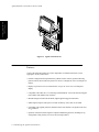
$JLOHQW0$996HULHV6HUYLFH*XLGH
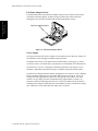
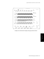
)LJXUH$JLOHQW996HULHV
Features
Some of the following features are release-dependent. For further information, see the
appropriate 7HFKQLFDO'DWD6KHHW.
• Flexible configuration and optional battery (Model V24CT/V26CT) permit monitoring
patients in most critical and acute patient care areas of a hospital as well as in transport situations.
• Displays up to four waves on a monochrome, or up to six waves on a color flat panel
display.
• Compatible with either the 6- or 8-slot Plug-in Satellite Rack. 6-slot rack docked configuration available with Model V24CT/V26CT.
• Movable design includes built-in handle, lightweight and rugged construction.
• Small footprint requires little space to mount on table top, wall, shelf, or roll stand.
• Compatible with Agilent parameter modules and recorder module (except EEG, FiO2 and
SvO2 modules).
• Operation consistent with all Agilent Component Monitoring Systems, including set-up,
configuration, other patients (overview) and record procedures.
,QWURGXFLQJWKH$JLOHQW996HULHV
$JLOHQW0$996HULHV6HUYLFH*XLGH
• Compatible with the Agilent patient care system.
• Offers optional ST Segment Analysis software which measures the elevation or depression
of the ST segment on up to 3 ECG leads and provides waveform recall capability.
• NBP measurements synchronized on a full hour.
• Displays three oxyCRG waveforms over a six-minute period.
• Neonatal Event Review to automatically detect, store, display and document up to 24 neonatal cardiorespiratory and hypoxic events over a period of 24 hours. Events can be manually selected and stored, and print-outs of neo-events and oxyCRG can be done at local or
central printer.
• Neonatal event review print-out capability
• Basic arrhythmia in the bedside monitor; enhanced arrhythmia monitoring via Agilent
patient care system connection to a host of Agilent arrhythmia monitoring systems.
• Point-of-care Blood Analysis module, using single-use disposable cartridges.
• Desaturation alarm.
• Recordings available using the thermal array recorder module, and through Central Station
recorders.
• 12-lead ECG derived using the EASI™ algorithm1, requiring only the standard 5-lead set.
• EASI1 print-out capability for 12-lead EASI1 ECG
• Improved performance of the SpO2 algorithm providing a more reliable measurement at
low perfusion and during patient movement.
• New appearance of screen elements including softkeys and task windows gives the look
and feel of the latest graphical user interface.
• Five screen configurations, each including the application window (including oxyCRG,
split-screen, CSA) and numerics on/off.
• Venous puncture facility with the NBP module, used for drawing blood or applying venous
lines – the patient cuff is inflated to a patient size-dependent pressure for a predefined
period of time.
• Inexpensive to maintain and low cost of ownership. Optional no charge 5-year return-toAgilent warranty repair service available (U.S. only).
• Editable screen labels
1. EASI is a trademark of Zymed Inc.
,QWURGXFLQJWKH$JLOHQW996HULHV
Introducing the Agilent
V24/V26 Series
• Comprehensive Patient Data Management provides 24-hour storage of up to 16 continuously monitored parameters sampled at one-minute intervals.
$JLOHQW0$996HULHV6HUYLFH*XLGH
Introducing the Agilent
V24/V26 Series
Physical, Functional Overview
The Agilent V24/V26 Series is a versatile patient monitoring system, allowing user-specific
customization using a variety of hardware and software components.
These components include:
• Mainframe
• Monochrome or Color Flat Panel for display of up to six waveforms
• Eight-slot Satellite Rack or optional six-slot Plug-in Satellite Rack
• All parameter modules (except EEG, FiO2 and SvO2) supported by Agilent M1165A/66A/
67A and M1175A/76A/77A Component Monitoring System, and Agilent M1275A
Component Transport System
• Agilent patient care system interface
• RS-232 Serial Interface (optional)
• Patient Data Management software
• ST segment analysis software
• OxyCRG display software
• Basic arrhythmia
• Extended arrhythmia detection when networked to one of Agilent’s Arrhythmia Systems
• Agilent M1026A Anesthesia Gas Module (AGM) support
• Two sealed lead acid rechargeable batteries (Model V24CT/V26CT)
• Model V24CT/V26CT can be operated on AC power or battery.
0DLQIUDPH
The mainframe contains the display unit and computer module which controls all parameter
inputs, display output and interfacing capabilities for the Agilent V24/V26 Series.
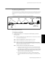
'LVSOD\
The Agilent Models V24/V24C/V24CT allows 4 simultaneous waveforms, and the Models
V26C/V26CT up to 6 simultaneous waveforms, in fixed trace mode. Moving trace mode is
supported for Cardiac Output waveform, oxyCRG and trends. Overlapped wave format is
supported for the bottom 2 waves only (maximum of 2 waves may be overlapped with the
waves differentiated by dashed lines).
,QWURGXFLQJWKH$JLOHQW996HULHV
$JLOHQW0$996HULHV6HUYLFH*XLGH
+5
70
)+5
38/6(
67
67
P9
$%3
$%3
135/72 (94)
3$3
3/(7+
6S2
97
6S2
&2
64,
(7&2
20
,0&2
$:55
$ODUP9RO
1%3
4569RO
)LJXUH([DPSOHRI0DLQ6FUHHQ'LVSOD\
The Flat Panel display assembly consists of a backlit, high-contrast monochrome or color
panel with an anti-glare screen for superior readability.
The monochrome display consists of a 9.5" (diagonal measurement) monochrome display.
The display is a 640 x 480 pixel full dot graphic display unit consisting of the Flat Panel
display, Cold Cathode Fluorescent Tube (CCFT) for backlighting, and Flat Panel row and
column driver circuits.
The old and the new color displays consist of a 10.4" (diagonal measurement) color Flat
Panel display. The display is a 640 x 480 pixel full dot graphic display unit consisting of a
TFT Active Matrix Color Flat Panel.
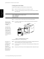
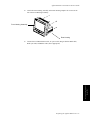
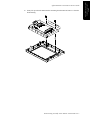
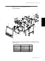
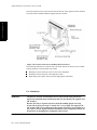
Flat Panel DISPLAY PANEL
FRONT HOUSING
KEYPAD
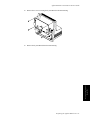
)LJXUH$JLOHQW996HULHV'LVSOD\)URQW9LHZ
,QWURGXFLQJWKH$JLOHQW996HULHV
Introducing the Agilent
V24/V26 Series
,&8$GXOW$SULO
,,
$JLOHQW0$996HULHV6HUYLFH*XLGH
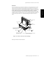
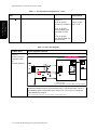
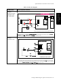
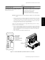
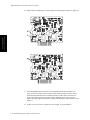
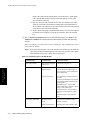
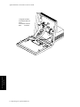
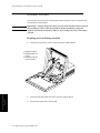
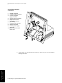
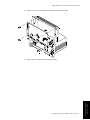
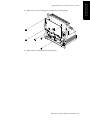
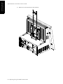
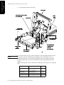
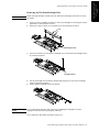
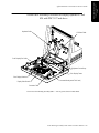
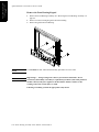
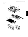
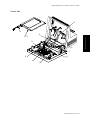
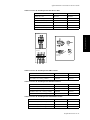
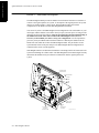
6\VWHP%RDUG
The microprocessors for the Agilent V24/V26 Series are all contained on the System Board.
The System Board contains the circuitry to control all key operational functions including:
Introducing the Agilent
V24/V26 Series
• Acquire and process all physiological data from the plug-in parameter modules.
• Control all outputs to the Flat Panel display.
• Process the inputs created by keystrokes from the front panel keypad.
• Create tones for audible alarms.
• Interface to the Agilent monitoring network (SDN) system.
127(
If you have the SDN daughter card installed in your Model V24, it will be different than the
one shown in the illustration. Refer to Appendix A for information on the Model V24 with
the Agilent monitoring network (SDN) daughter card. System Board interface
connectors:
1. Keypad connector
2. Flat Panel Data Connector
3. 5V and 12V power
supply connector
4. Service ports (not cabled)
5. SDN interface cable
6. Defib sync connector
(not cabled)
7. Front-end link connector
8. Speaker connector
9. 60 VDC power supply
connector
10. RS-232 connector (with
option J13)
6
7
5
2
1
9
10
4
3
8
Service Port Cover
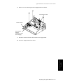
)LJXUH,QVWUXPHQWVKRZQZLWK)URQW3DQHOUHPRYHG
,QWURGXFLQJWKH$JLOHQW996HULHV
$JLOHQW0$996HULHV6HUYLFH*XLGH
,QWHUIDFH&RQQHFWLRQV
$JLOHQW3DWLHQW&DUH6\VWHP1HWZRUN
A single upstream Agilent monitoring network (SDN) connector allows connection to an
Agilent patient care system network. This allows the V24/V26 Series to access waveforms,
numerics, and alarms from other networked patient monitoring bedsides. It also allows
connection to an Agilent central station and Agilent extended arrhythmia monitoring
systems.
56,QWHUIDFH
A single RS-232 connector allows connection to the MEdical Computer InterFace (MECIF).
This allows the V24/V26 Series to transfer data from the system to a MECIF compatible
device or Agilent M1026A Anesthesia Gas Module (AGM). Alternatively the RS-232 port
can be used to connect to a local printer to provide local printing capability.
)URQW(QG/LQN
The plug-in rack is connected to the mainframe by a cable that plugs into a serial front-end
link connector located on the side of the V24/V26 Series.
6HUYLFH3RUWV
The V24/V26 Series application and utility processors have dedicated service ports. Each
service port allows connection to the CPC Flash Programming Tool, which is used for
configuring the instrument and upgrading product software. The CPC Flash Programming
Tool is a compact service tool which executes software stored on a Flash Memory Card and is
used with other Agilent patient monitors. For details on using the CPC Flash Programming
Tool refer to Chapter 2 Testing & Maintaining the Agilent V24/V26 Series
'HILEULOODWRU6\QF2XWSXW&RQQHFWRU
The patient monitor includes a side panel analog jack output for ECG signal, Defibrillator
and balloon pump sync signal and defib marker insertion. The ECG output specifications are:
• Signal gain: 320 to 3200 depending on display gain
• Full scale display: 3.2 Vpp
• Signal delay: <30 ms
$&3RZHU&RQQHFWRU
A standard CEE connector (IEC Type 320) is located at the rear of the V24/V26 Series. A
detachable country-specific line cord is supplied.
,QWURGXFLQJWKH$JLOHQW996HULHV
Introducing the Agilent
V24/V26 Series
The System Board controls all interfaces to the instrument including:
$JLOHQW0$996HULHV6HUYLFH*XLGH
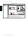
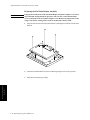
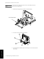
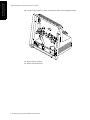
)ODW3DQHO$GDSWHU%RDUG
Introducing the Agilent
V24/V26 Series
The Monochrome Model V24 Flat Panel adapter board provides an interface between the
monochrome Flat Panel display assembly and System Board. The board contains the
backlight inverter assembly, Flat Panel bias and contrast/brightness circuitry.
Flat Panel Adapter Board
)LJXUH)ODW3DQHO$GDSWHU%RDUG
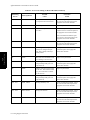
3RZHU6XSSO\
The Agilent V24/V26 Series power supplies convert input power into three DC voltages for
the mainframe and for the plug-in modules in the plug-in rack.
The Model V24CT/V26CT can operate from an internal battery power supply, or from an
external AC source. The internal power is provided by two rechargeable, removable batteries.
The batteries are 12 Volt, 2.3 Amp-Hour, sealed lead acid batteries. The battery’s rate of
discharge is dependent on the number and type of modules being used with the monitor.
The batteries are charged while the monitor is plugged in to an external AC source. Depleted
batteries should be charged as soon as possible. When using the external AC source, the
recharge time takes approximately 4 hours to a 90% capacity if the monitor is off. If the
monitor is on, the charge time takes considerably longer (approximately 16 hours). An
alternative method for recharging the batteries is to remove the batteries from the monitor
and charge them using the Agilent M1278A External Battery Charger. The M1278A charges
up to 4 batteries at a time and reduces the charge time to 2.5 hours.
,QWURGXFLQJWKH$JLOHQW996HULHV
$JLOHQW0$996HULHV6HUYLFH*XLGH
3RZHU6XSSO\2XWSXW9ROWDJH
Monochrome Model V24
Color Model V24C/V26C
Color Model V24CT/V26CT
+5 Volts @ 2.0 Amps, max
+5 Volts @ 2.5 Amps, max
+5 Volts @ 2.8 Amps, max
+12 Volts @ 2.0 Amps, max
+12 Volts @ 0.75 Amps, max
+12 Volts @ 0.65 Amps, max
+60 Volts @ 0.35 Amps, max
+60 Volts @ 0.35 Amps, max
+60 Volts @ 0.3 Amps, max
3RZHU6XSSO\,QSXW9ROWDJH
The power supply uses the following input voltages:
• AC Input: 90 to 250 VAC continuous, 48 to 66 Hz
• Maximum Power Consumption: 150 Volt-Amperes
%DWWHU\3RZHU6XSSO\
Capacity: At least 1 hour on full charge at 25°C (77°F) with two batteries. For example, the
discharge time for the module configuration option #A24 (with ECG/Resp, NBP, SpO2,
Pressure, Recorder) is 1 hour. The discharge time for the module configuration option #A22
(with ECG/Resp, NBP, SpO2, Pressure) is 1 hour 15 minutes.
Charging time: 4 hours to 90% of full capacity if monitor is off. 16 hours to 90% of full
capacity if monitor is on.
If the Agilent Battery Charger (M1278A) is used, the charging time is 2.5 hours to 90%
capacity.
,QWURGXFLQJWKH$JLOHQW996HULHV
Introducing the Agilent
V24/V26 Series
The following table depicts the slight Power Supply output voltage differences between the
monochrome Model V24, color Model V24C/V26C, and color battery Model V24/V26.
$JLOHQW0$996HULHV6HUYLFH*XLGH
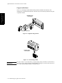
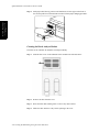
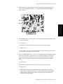
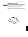
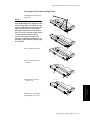
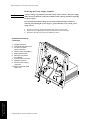
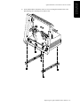
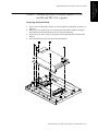
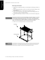
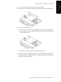
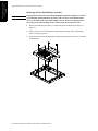
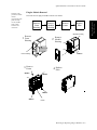
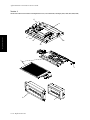
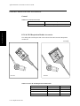
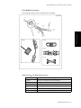
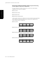
3OXJLQ6DWHOOLWH5DFN
Introducing the Agilent
V24/V26 Series
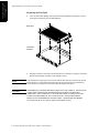
The 6- or 8-slot Plug-in Satellite Rack houses parameter modules and connects to the
mainframe by a standard front end cable. The rack may be conveniently mounted on IV pole
or patient’s bedside.
STANDARD 8 SLOT
PLUG-IN RACK
PARAMETER MODULES
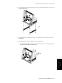
)LJXUH(LJKW6ORW3OXJLQ5DFN
OPTIONAL 6 SLOT
PLUG-IN RACK
)LJXUH6L[6ORW3OXJLQ5DFN
:$51,1*
Do not connect a second rack by a cable when using a module rack docked to
the back of the Agilent Model V24CT/V26CT. Using a second rack connected
by a cable may disrupt module communication.
,QWURGXFLQJWKH$JLOHQW996HULHV
$JLOHQW0$996HULHV6HUYLFH*XLGH
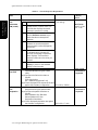
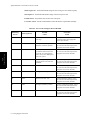
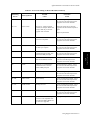
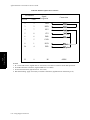
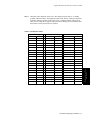
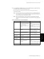
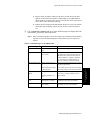
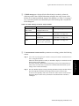
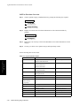
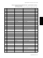
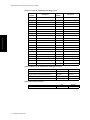
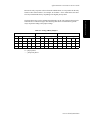
3DUDPHWHU0RGXOHV
3DUDPHWHU
0RGXOH
0RGHO1XPEHU
1XPEHU6XSSRUWHG
M1001A/B
ECG
M1002A/B
ECG/RESP
M1006A/B
Pressure (invasive)
Maximum of three per monitor *
M1006A/B Option #C01
Pressure (invasive) Module
with Analog Pressure Output
Maximum of one per monitor (total of three invasive pressure modules possible) *
M1008A
NBP
M1008B
NBP Adult/Neonatal
M1012A
Cardiac Output
M1015A
Sidestream CO2
M1016A
CO2
M1018A
tcpO2/tcpCO2
Maximum of one per monitor – only with Neonatal
options
M1020A
SpO2 /PLETH
Maximum of one per monitor
M1029A
Temperature
Maximum of two per monitor *
M1032A
VueLink
Maximum of one VueLink A and one/two VueLink B per
monitor *
M1116A or M1116B
Thermal Array Recorder
Maximum of one per monitor
1026A
Anesthetic Gas
Module
Maximum of one per monitor – only with Anesthesia
options *
1022A
Blood Analysis
Module
Maximum of one per monitor *
M1034A
BIS Module
Maximum of one per monitor - only with Anesthesia
options *
Maximum of one M1001A/B or M1002A/B per monitor.
Maximum of one per monitor *
Maximum of one per monitor *
Maximum of one per monitor *
* Bundle-specific
127(
For details of performance specifications of each parameter module see the relevant
7HFKQLFDO'DWD6KHHW.
,QWURGXFLQJWKH$JLOHQW996HULHV
Introducing the Agilent
V24/V26 Series
The Agilent V24/V26 Series provides 6 or 8 slots to support the following parameter
modules (Release C.0):.
$JLOHQW0$996HULHV6HUYLFH*XLGH
Introducing the Agilent
V24/V26 Series
)URQW3DQHO
The Agilent V24/V26 Series front panel contains the controls and indicators which operate
the instrument. The front panel comprises softkeys and hardkeys. The softkeys perform
multiple functions which correspond to labels displayed at the bottom of the screen. When no
softkey labels are on the screen, the softkeys do not function. The hardkeys perform the
function defined by the key. There are two types of hardkeys:
• Blue hardkeys – Each of these hardkeys displays specific selection windows where adjustments and changes can be made.
• Gray hardkeys – Each of these hardkeys performs the specific action indicated by the label.
Red Yellow
Alarm Alarm
Confirm
Silence/
Reset
Alarms
0 ON
Monitor
Setup
Realtime
Record
Main
Screen
Suspend
OFF
Other
Patients
Procedures
Trends/
Calcs
Module
Setup
Delayed
Record
1
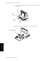
)LJXUH$JLOHQW0RGHOV99&9&)URQW3DQHO
Red Yellow
Alarm Alarm
Confirm
Silence/
Reset
Alarms
Main
Screen
Suspend
OFF
0 ON
Other
Patients
Monitor
Setup
Realtime
Record
Procedures
Delayed
Record
Trends/
Calcs
Battery
Charging
Module
Setup
Battery
Charged
AC
Power
1
)LJXUH$JLOHQW0RGHO9&79&7)URQW3DQHO
The Agilent Model V24CT/V26CT front panel shows the status of the battery and line power
supplies. See “Agilent Model V24CT/V26CT Front Panel Indicators” on page 1-14 for
indicator descriptions.
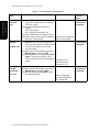
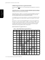
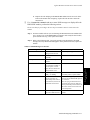
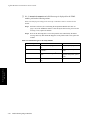
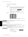
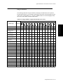
+DUGNH\)XQFWLRQV
The following table describe the hardkey functions:
,QWURGXFLQJWKH$JLOHQW996HULHV
$JLOHQW0$996HULHV6HUYLFH*XLGH
127(
+DUGNH\
'HVFULSWLRQ
$ODUPV
3UHVVLQJWKLVNH\GLVSOD\VDVHOHFWLRQZLQGRZWKDWDOORZV
DODUPVWREHVXVSHQGHGRUVZLWFKHGRQDOORZVDODUPOLPLWV
WREHVHWDQGUHYLHZHG
6XVSHQG
3UHVVLQJWKLVNH\WRJJOHVWKH$ODUPV6XVSHQGVWDWH
6LOHQFH5HVHW
3UHVVLQJWKLVNH\VLOHQFHVDQDODUP,IWKHFDXVHRIWKHDODUP
KDVEHHQHOLPLQDWHGSUHVVLQJWKLVNH\UHVHWVWKHDODUP
0RQLWRU6HWXS
3UHVVLQJWKLVNH\GLVSOD\VDVHOHFWLRQZLQGRZWKDWDOORZV
YDULRXVPRQLWRUVHWXSVLQFOXGLQJFKDQJLQJWKHGLVSOD\
OD\RXW<RXPD\VHOHFWDVVLJQVSHFLILFZDYHIRUPVDQGWKH
PRGHLQZKLFKWKH\DUHGLVSOD\HGIRUH[DPSOHIRXUZDYHV
QRQRYHUODSSLQJRUIRXUZDYHVZLWKWKHERWWRPWZRZDYHV
RYHUODSSHG
3URFHGXUHV
3UHVVLQJWKLVNH\DOORZV\RXWRUHYLHZWKHSDWLHQW¶V&XUUHQW
+HLJKWOHQJWKIRUQHRQDWHVDQG&XUUHQW:HLJKWHQWU\IRU
FDUGLDFLQGH[FDOFXODWLRQ7KHYDOXHVIRUWKHSDWLHQWKHLJKW
DQGZHLJKWDUHDGMXVWHGXVLQJWKHDUURZNH\VWRLQFUHPHQW
RUGHFUHPHQWWKHFXUUHQWO\VHOHFWHGOLQH7KLVNH\DOVRJLYHV
DFFHVVWR67DQG&2LIDYDLODEOH
7UHQGV
&DOFV
3UHVVLQJWKLVNH\GLVSOD\VDVHOHFWLRQZLQGRZIRUUHYLHZLQJ
VHYHUDOSDWLHQWGDWDVFUHHQVLQFOXGLQJ7DEOH'LVSOD\*UDSKV
'LVSOD\5HYLHZ$GPLW7UHQGLQJ3ULRULW\$UUK\WKPLD
5HSRUWVR[\&5*HWF
0RGXOH6HWXS
3UHVVLQJWKLVNH\GLVSOD\VDVHOHFWLRQZLQGRZWKDWDOORZV\RX
WRFKDQJHRUDGMXVWSDUDPHWHUVHWWLQJVVXFKDVWXUQ
SDUDPHWHUVRQRURIIFKDQJHVRXUFHIRUKHDUWUDWHSXOVHHWF
0DLQ6FUHHQ
3UHVVLQJWKLVNH\UHWXUQVWKHGLVSOD\WRWKHVWDQGDUG
PRQLWRULQJVFUHHQ
5HDOWLPH
5HFRUG
3UHVVLQJWKLVNH\JHQHUDWHVDUHDOWLPHUHFRUGLQJ
'HOD\HG
5HFRUG
3UHVVLQJWKLVNH\JHQHUDWHVDGHOD\HGUHFRUGLQJ
$UURZ.H\V
7KHDUURZVFRQVLVWRIXSGRZQOHIWULJKWNH\V7KHVHNH\V
IXQFWLRQRQO\ZKHQLOOXPLQDWHG7KHDUURZNH\VDOORZ\RX
WRPRYHEHWZHHQGLIIHUHQWDUHDVRIWKHRSHUDWRUVFUHHQVWR
PDNHVHOHFWLRQVSHUIRUPSURFHGXUHVRUDGMXVWVHWWLQJV
&RQILUP.H\
3UHVVLQJWKH&RQILUP.H\FRQILUPVDQGHQWHUV
FRQILJXUDWLRQFKDQJHV\RXPDNHWRWKHLQVWUXPHQW7KH
FRQILUPNH\ZRUNVRQO\ZKHQLOOXPLQDWHG:KHQFRPSOHWLQJ
\RXUFKDQJHVWRWKHFRQILJXUDWLRQDPHVVDJHDSSHDUVRQWKH
VFUHHQSURPSWLQJ\RXWRSUHVVWKHNH\
2WKHU3DWLHQWV
3UHVVLQJWKLVNH\DOORZV\RXWRDFFHVV2YHUYLHZ&RQWUROV
DQGVHQGDQGUHFHLYHDODUPVDWVHOHFWHGJURXSV
For additional information on the hardkey functions and operating procedures, refer to the
$JLOHQW996HULHV8VHU¶V*XLGH. For information on configuring the Agilent V24/V26
Series, refer to the $JLOHQW996HULHV,QVWDOODWLRQDQG&RQILJXUDWLRQ*XLGH.
,QWURGXFLQJWKH$JLOHQW996HULHV
Introducing the Agilent
V24/V26 Series
7DEOH)URQW3DQHO+DUGNH\)XQFWLRQV
$JLOHQW0$996HULHV6HUYLFH*XLGH
$JLOHQW0RGHO9&79&7)URQW3DQHO,QGLFDWRUV
Introducing the Agilent
V24/V26 Series
Confirm
Trends/
Calc
Delayed
Record
Module
Setup
Battery
Charging
AC
Power
Battery
Charged
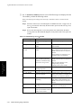
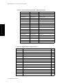
The front panel of the Model V24CT/V26CT has the following indicators:
• AC Power - indicates the Model V24CT/V26CT is connected to an AC power source.
• Battery Charged - indicates the batteries are charged and can support battery operation.
• Battery Charging - indicates the Model V24CT/V26CT is connected to an AC power
source and the batteries are being charged.
The Battery Charged and the Battery Charging LEDs work together to display the status of
the battery charging sequence. The following table describes the sequence.
7DEOH/('3DWWHUQ'XULQJ&KDUJH6HTXHQFH
Residual Capacity
Charging LED
Charged LED
Up to 40%
Flashing
Off
More than 40%, Less than 90%
Steady
Off
More than 90%
Off
Steady
,QWURGXFLQJWKH$JLOHQW996HULHV
$JLOHQW0$996HULHV6HUYLFH*XLGH
There are two different types of interfaces available. One is the Agilent patient care system
interface which comes standard with most Agilent V24/V26 Models. The second type of
interface, the RS-232 interface, is optional and permits MECIF connectivity for data transfer
to other computers and connection to the Agilent Anesthesia Gas Module. Alternatively, the
RS-232 option can be used to provide local printing capability. Figure 1-10 “Interface
Connections on Rear Housing(s)” shows the location of Agilent monitoring network (SDN)
and RS-232 interface connections on the two types of currently supported rear housings; rear
housings with a prefix serial code < 3608 and rear housings with a prefix serial code >=
3608.
DEFIB CONNECTOR
AC LINE INPUT
RACK
CONNECTOR
RS-232 CONNECTOR
(Rear Housings with
Serial Prefix < 3608)
PROTECTIVE GROUND
RS-232 CONNECTOR
(Rear Housings with
Serial Prefix >= 3608)
EQUIPOTENTIAL GROUND
AGILENT VIRIDIA MONITORING NETWORK (SDN)
SINGLE CONNECTOR
)LJXUH,QWHUIDFH&RQQHFWLRQVRQ5HDU+RXVLQJV
Both types of interfaces are discussed below.
,QWURGXFLQJWKH$JLOHQW996HULHV
Introducing the Agilent
V24/V26 Series
,QWHUIDFHV
$JLOHQW0$996HULHV6HUYLFH*XLGH
$JLOHQW3DWLHQW&DUH6\VWHP,QWHUIDFH
Introducing the Agilent
V24/V26 Series
:KDWLVWKH$JLOHQW
SDWLHQWFDUHV\VWHP"
$JLOHQWSDWLHQWFDUH
V\VWHPDOVRNQRZQDV
$JLOHQWPRQLWRULQJ
QHWZRUN6'1LVD
ORFDODUHD
FRPPXQLFDWLRQV
QHWZRUNGHVLJQHGWR
VKDUHSDWLHQWGDWD
DPRQJEHGVLGH
LQVWUXPHQWV&HQWUDO
6WDWLRQVUHFRUGHUV
SULQWHUVFRPSXWHU
V\VWHPVDQGRWKHU
LQIRUPDWLRQV\VWHPV
FRQQHFWHGWRWKH$JLOHQW
PRQLWRULQJQHWZRUN
6'1
7KH$JLOHQWPRQLWRULQJ
QHWZRUN6'1LVD
GLJLWDOFRPPXQLFDWLRQV
QHWZRUNWKDWDOORZV
UHDOWLPHWUDQVIHURI
GLJLWDOL]HGSDWLHQWGDWD
EHWZHHQWKHVH
LQVWUXPHQWV7KH
FRPPXQLFDWLRQV
SURWRFROGDWD
IRUPDWWLQJDQG
KDUGZDUH
LPSOHPHQWDWLRQ
DFFRPPRGDWHVDYDULHW\
RIFRPPXQLFDWLRQV
QHHGVIRUSUHVHQWDQG
IXWXUHH[SDQVLRQ
When connected to the Agilent patient care system network, or Agilent monitoring network
(SDN), the Agilent V24/V26 Series is capable of receiving and displaying current vital signs,
waves and alarms from other bedsides on the network. The Agilent monitoring network
(SDN) connection also allows connectivity to a Central Station and centralized arrhythmia
systems. The instrument has one Agilent monitoring network (SDN) connector (upstream
only); therefore it must be the last instrument on an Agilent monitoring network (SDN)
branch.
The Agilent monitoring network (SDN) interface subsystem consists of the physical
connection to the Agilent monitoring network (SDN) network and controlling firmware
resident on the System Board. (Your configuration may use an Agilent monitoring network
(SDN) daughter card. Refer to$SSHQGL[$for more information.) When the Agilent V24/
V26 Series is connected to the Agilent monitoring network (SDN), digitized patient
information is transmitted serially at regular intervals (called poll cycles) over branch cables
to the System Communications Controller (SCC). The SCC sequentially receives,
synchronizes and rebroadcasts the digitized patient information to all the instruments
connected to the Agilent monitoring network (SDN). Patient data is received for use by each
instrument by way of the Agilent monitoring network (SDN) interface circuitry resident in
each instrument.
Warning:
Connecting the Agilent monitoring network (SDN) cable when the product
is powered on is not supported. Error codes and Agilent monitoring network
(SDN) interface lock-up may occur. Power cycling the product will recover
the product. No permanent damage will result. To prevent unintentional
disruption in monitoring, be sure the SDN interface cable is properly
secured at both ends when connecting to the Agilent monitoring network
(SDN).
561HWZRUN
The optional RS-232 interface has one port that permits either MECIF connectivity, M1026A
AGM compatibility, connection to a personal computer, or local printing capability.
3DWLHQW'DWD0DQDJHPHQW
The Agilent V24/V26 Series provides Patient Data Management software, allowing you to:
• manage patient information
• view patient data in graphs or tables
• print patient information reports via an Agilent central station or local RS-232 printer.
,QWURGXFLQJWKH$JLOHQW996HULHV
$JLOHQW0$996HULHV6HUYLFH*XLGH
Specifications
For an overview of the functionality and options for each bundle in Releases A.0, B.0 and
C.0, please refer to Table “Release C.0 Functionality and Options,” on page 2-46 and Table
“Release A.0/B.0 Functionality and Options,” on page 2-47.
'LPHQVLRQDQG:HLJKW
The following table lists the dimensions and weight for both the 8-slot and 6-slot racks.
7DEOH5DFN'LPHQVLRQVDQG:HLJKW
Configuration
Mainframe without
plug-in rack
Dimensions (HxWxD)
0RGHOV99&
9&
28.0 x 32.0 x 25.0 cm
(11.0 x 12.6 x 10.2 in)
0RGHOV9&79&7
28.0 x 32.0 x 26.0 cm
(11.0 x 12.6 x 10.4 in)
Weight
0RGHOV99&9&
5.1 kg
(11.3 lbs)
0RGHOV9&79&7
6.7 kg without batteries
(14.8 lbs)
7.7 kg with batteries
(16.9 lbs)
8 slot rack without
modules
13.7 x 32.9 x 8.9 cm
(5.4 x 12.9 x 3.5 in)
1.1 kg
(2.4 lbs)
8 slot rack with
modules
13.7 x 32.9 x 13.0 cm
(5.4 x 12.9 x 5.1 in)
varies per configuration
6 slot rack without
modules
14.9 x 29.6 x 11.0 cm
(5.9 x 11.6 x 4.3 in)
1.1 kg
(2.4 lbs)
6 slot rack with
modules
14.9 x 29.6 x 15.0 cm
(5.9 x 11.6 x 5.9 in)
varies per configuration
Parameter Modules
Refer to relevant7HFKQLFDO'DWD6KHHW.
,QWURGXFLQJWKH$JLOHQW996HULHV
Introducing the Agilent
V24/V26 Series
)XQFWLRQDOLW\DQG2SWLRQ6HWV
$JLOHQW0$996HULHV6HUYLFH*XLGH
(QYLURQPHQWDO
Introducing the Agilent
V24/V26 Series
7HPSHUDWXUH5DQJH
2SHUDWLQJ
0RGHOV99&9& +5 to 40°C (41 to 104°F)
0RGHOV9&79&7 +5 to 35°C (41 to 95°F)
6WRUDJH
0RGHOV99&9& -20 to 60°C (4 to 140°F)
0RGHOV9&79&7 -15 to 40° C (5 to 104°F)
+XPLGLW\5DQJH
2SHUDWLQJ
0RGHOV99&9& 95% RH max @ 40°C (104°F) (Non-condensing)
0RGHOV9&79&7 95% RH max @ 35°C (95°F) (Non-condensing)
6WRUDJH
90% RH max @ 60°C (140°F)
$OWLWXGH5DQJH
2SHUDWLQJ
Up to 4,600 m (15,000 ft)
6WRUDJH
Up to 4,600 m (15,000 ft)
6DIHW\
Comply with UL2601, IEC 601-1, CSA C22.2 no. 601-1, EN60601-1, and EN60601-1-2 and
carries the CE mark to the Medical Device Directive in Europe.
$&,QSXW
90 to 250 Vac, 48 to 66 Hz, nominal
0D[SRZHUFRQVXPSWLRQ 150 Volt-Amperes
,QWURGXFLQJWKH$JLOHQW996HULHV
$JLOHQW0$996HULHV6HUYLFH*XLGH
3DWLHQW'DWD0DQDJHPHQW
0D[LPXPQRRISDUDPHWHUV 16
6DPSOH,QWHUYDO 12 seconds, or 1 minute average (average of five 12-second intervals).
0D[LPXPQRRIYDOXHVIRUHDFKSDUDPHWHU1441.
6WRUDJH up to 24 hours.
$SHULRGLFDOO\$FTXLUHG'DWD
0D[LPXPQRRISDUDPHWHUV 76
0D[LPXPQRRIYDOXHVIRUHDFKSDUDPHWHU 48/96 (bundle specific).
6WRUDJH up to 24 hours.
7DEXODU7UHQGV9LWDO6LJQV
7LPHFROXPQVSHUVFUHHQ 8.
3DUDPHWHUURZVSHUVFUHHQ up to 13.
&ROXPQLQWHUYDO 1 minute to 3 hours.
*UDSKLF7UHQGV
*UDSKVSHUVFUHHQ up to 3 parameters.
'DWDUHVROXWLRQ 12 seconds or 1 minute average.
'XUDWLRQ 1, 2, 8, 16, 24 hours (1 minute resolution). 1 or 4 hours (12 second resolution).
5HVROXWLRQ up to 450 data points along the X-axis.
,QWURGXFLQJWKH$JLOHQW996HULHV
Introducing the Agilent
V24/V26 Series
&RQWLQXRXVO\$FTXLUHG'DWD
$JLOHQW0$996HULHV6HUYLFH*XLGH
'LVSOD\
Introducing the Agilent
V24/V26 Series
0RQRFKURPH'LVSOD\In Release B.0: white-on-black presentation using monochrome
backlit Flat Panel display. Previous releases support black-on-white presentation as well as
white-on-black.
'LVSOD\VL]H 24.13 cm (9.5 in diagonal measure)
&RORU'LVSOD\Flat panel color display
'LVSOD\VL]H 26 cm (10.4 in diagonal measure)
7KHUHPDLQLQJ'LVSOD\UHODWHGVSHFLILFDWLRQVSHUWDLQWRDOOPRGHOV
'LVSOD\5HVROXWLRQ 640 x 480 Pixels
:DYHIRUP/HQJWK 12.95 cm (5.1 in) [5.2 sec@ 25mm/sec]
:DYHIRUP+HLJKW 2.8 cm (1.1 in) [4-channel]
1RUPDO&KDUDFWHU6L]H 3 x 5.3 mm (.12 x.21 in)
3DUDPHWHU0RGXOHV
See Table 1-5, “Release C.0 Functionality and Options,” on page 1-46 and Table 1-6,
“Release A.0/B.0 Functionality and Options,” on page 1-47 for the types of parameter
modules that can be used with the V24/V26 Series.
Refer to the relevant 7HFKQLFDO'DWD6KHHW for Agilent parameter module specifications.
3OXJLQ6DWHOOLWH5DFNV
The following table gives the Satellite Rack specifications.
7DEOH3OXJLQ6DWHOOLWH5DFN6SHFLILFDWLRQV
Plug-in Satellite
Rack
Maximum no. of
modules
Maximum
Plug-in Racks
M1041A (standard)
8 single-width modules
one
4 m (13.1 ft)
M1276A (optional)
6 single-width modules
one
4 m (13.1 ft)
Cable length
Mounting Options
For information on mounting options please refer to Agilent’s mounting website
http://www.healthcare.agilent.com/mpgpmd/vmount and to the Installation Notes shipped
with the mounting devices.
,QWURGXFLQJWKH$JLOHQW996HULHV
$JLOHQW0$996HULHV6HUYLFH*XLGH
To check your understanding, please answer the following questions. After completing this exercise, check your
answers to those provided at the end of this chapter.
1. Why should the Agilent V24/V26 Series be the last instrument on an Agilent monitoring network (SDN)
branch?
_________________________________________________________________
_________________________________________________________________
2. The instruments’ displays do NOT show _________.
a.
b.
c.
d.
e.
6 minutes of OxyCRG
4 Waves
8 Waves
Overview
ST segment analysis
3. The instruments will present _____________________ when networked to an Agilent arrhythmia monitoring
system.
a.
b.
c.
arrhythmia status messages only
arrhythmia status messages and delayed annotated waveform only
arrhythmia status messages, delayed annotated waveform, and arrhythmia data
management
4. Which function does the System Board include?
a.
b.
c.
d.
e.
f.
g.
Process keystrokes from the front panel keypad.
Acquire and process physiological data from the plug-in parameter modules.
Create tones for audible alarms.
Controls the interface to the Flat Panel display.
Controls the interface to the Agilent Patient Care System Network.
Controls the RS-232 interface
All of the above
,QWURGXFLQJWKH$JLOHQW996HULHV
Introducing the Agilent
V24/V26 Series
Practice Exercise
$JLOHQW0$996HULHV6HUYLFH*XLGH
Introducing the Agilent
V24/V26 Series
5. What is the display resolution of the instruments?
a.
b.
c.
d.
e.
460 x 280 Pixels
640 x 480 Pixels
820 x 480 Pixels
1020 x 640 Pixels
none of the above
6. What parameter module(s) are NOT compatible with the instruments?
a.
b.
c.
d.
e.
f.
g.
SvO2
ssCO2
Data Transfer
FiO2
SpO2/PLETH
I-STAT
EEG
7. The Agilent V24/V26 Series has an RS-232 interface.
a.
b.
c.
true
false
optional
8. Which key allows you to change or adjust parameter settings?
a.
b.
c.
d.
e.
Monitor Setup
Module Setup
Procedures
Trends
Main Screen
,QWURGXFLQJWKH$JLOHQW996HULHV
$JLOHQW0$996HULHV6HUYLFH*XLGH
The instruments only have one upstream Agilent monitoring network (SDN) connector.
c. 8 Waves
c. Arrhythmia status messages, delayed annotated waveform, and arrhythmia data
management
g. All of the listed functions.
b. 640 x 480 Pixels
a. SvO2
d. FiO2
g. EEG
c. optional
b. Module Setup
,QWURGXFLQJWKH$JLOHQW996HULHV
Introducing the Agilent
V24/V26 Series
3UDFWLFH([HUFLVH$QVZHUV
Introducing the Agilent
V24/V26 Series
$JLOHQW0$996HULHV6HUYLFH*XLGH
,QWURGXFLQJWKH$JLOHQW996HULHV
$JLOHQW0$996HULHV6HUYLFH*XLGH
Testing & Maintaining the Agilent V24/V26
Series
The first section in this chapter, “Test and Inspection Requirements”, describes the
procedures required to ensure that the Agilent V24/V26 Series monitor is in safe
working order. The following sections describe recommended procedures for
maintaining the equipment. These procedures apply to all versions of the Agilent V24/
V26 Series except as stated.
The procedures are grouped as follows:
• Test and Inspection Requirements — safety tests and periodic preventive
maintenance
• Performing General Inspections of the System
• Cleaning Procedures
• Performing Accuracy and Calibration Procedures
Objectives
In order to meet the chapter’s goals, you should be able to:
• Perform required safety checks and maintenance procedures.
• Perform a general inspection of the system.
• Clean the major units of the system.
Concepts
The V24/V26 Series has different levels of preventive maintenance and checks that
should be performed on a periodic basis or as recommended.
The procedures described in this chapter should be performed at the specified time
intervals to ensure effective preventive maintenance. The checklist may be
photocopied, completed by the maintainer, and filed for reference.
7HVWLQJ0DLQWDLQLQJWKH$JLOHQW996HULHV
Testing & Maintaining
the Agilent V24/V26
Series
Chapter 2
$JLOHQW0$996HULHV6HUYLFH*XLGH
0DLQWHQDQFH&KHFNOLVW
Testing & Maintaining
the Agilent V24/V26
Series
&KHFN+HUH 7RSLFVLQWKLV&KDSWHU
Test and Inspection Requirements
When to Perform Test Blocks
Power On and Performance Tests
Safety Tests
General Inspections of the System
Inspect the System Hardware
Inspect the Cables and Cords
Inspect the LEDs of the System
Inspect the Flat Panel Display
Inspect the Controls of the System
Performance Assurance Test
Performance Assurance Test
Preventive Maintenance
Replacement of Backlight Tube Assembly
Battery Care and Handling
Cleaning and Disinfecting Procedures
General Cleaning of the System
General Disinfecting of the System
Cleaning the Recorder Module
Cleaning the Blood Analysis Module
Upgrade and Cloning Instructions
Parts Checklist
Connecting the Flash Programming Tool
Upgrading the Utility CPU Software
Upgrading the Application CPU Software
Performing an EEPROM Upgrade
EEPROM Number Tables
Performing EEPROM Cloning
EEPROM Upgrades Between Application Bundles
7HVWLQJ0DLQWDLQLQJWKH$JLOHQW996HULHV
6HH3DJH
2-3
2-5
2-11
2-15
2-15
2-16
2-16
2-17
2-18
2-19
2-19
2-23
2-24
2-25
2-26
2-30
2-31
2-34
2-36
2-39
2-41
2-43
2-50
2-52
$JLOHQW0$996HULHV6HUYLFH*XLGH
This section is intended primarily for Agilent customer engineers and lists the test
requirements for servicing, installation and preventive maintenance. For some tests it
is required that the Agilent engineer documents the results in a service record.
Table 1-1 “When to Perform Test Blocks” explains when to perform the procedures.
Table 1-2 “Test and Inspection Requirements” explains the procedures to be
performed. Table 1-3 “Test and Inspection Requirements – Safety” explains the
procedures to be performed and gives full details of the Safety Tests.
Note: Only Agilent service engineers are required to report the results of the
following safety and performance tests back to the factory. Of the performance tests,
only those for NBP and Sidestream CO2 need to be reported.
7DEOH:KHQWR3HUIRUP7HVW%ORFNV
6HUYLFH(YHQW
±:KHQWR3HUIRUP
7HVW%ORFNV5HTXLUHG
&RPSOHWHWKHVHWHVWV
Installation of M1205A with NO
System (SDN) or with Medical
equipment connections (ex. AGM or
Vuelink)
Perform Visual and Power On test blocks (see page 2-5).
Installation of M1205A that is
connected to a System (SDN)
Perform Visual and Power On test blocks. If the 78581A safety
test (see the 78581A service manual) has passed previously no
further safety tests are required. If the 78581A safety test has
not been performed, it must be completed.
Installation of monitor that has RS232
connections to non-medical devices
(for example, Laser Printer or PC)
Perform Visual and Power On test blocks (see page 2-5).
Perform Safety (1) test block (see page 2-11).
Repairs where the power supply or
rear housing assembly is replaced
Perform Power On and Safety (2) test blocks (see page 2-11).
Repairs where the monitor has been
dropped
Perform Power On and Safety (2) and (3) test blocks (see page
2-12).
All other M1205A repairs, Hardware
or Software Upgrades
Perform Power On test block.
Preventive Maintenance1
Perform the NBP and Sidestream CO2 Module Performance
test blocks every year (see page 2-6).
For the BIS module no periodic preventive maintenance is
required.
Performance Assurance and Safety
Tests2
Perform all other Performance and Safety test blocks (1), (2)
and (3) once every two years.
1.
2.
For Germany only: For modules that do not have the CE mark, contact the Customer Response Center in
Ratingen for information.
For theBIS module performance and safety testing is optional (Agilent recommends yearly testing).
However, safety testing (Safety test block (3)) is required if there is suspected liquid ingress or after
everytime the case of any of the BIS components has been opened.
7HVWLQJ0DLQWDLQLQJWKH$JLOHQW996HULHV
Testing & Maintaining
the Agilent V24/V26
Series
Test and Inspection Requirements
$JLOHQW0$996HULHV6HUYLFH*XLGH
Testing & Maintaining
the Agilent V24/V26
Series
:$51,1*
8VHRQO\WKHSRZHUFRUGVXSSOLHGZLWKWKHLQVWUXPHQW8VHRQO\DWKUHH
ZLUHUHFHSWDFOHWKDWLVSURSHUO\JURXQGHG
:KHQFRQQHFWLQJDQRQPHGLFDOGHYLFHVXFKDVDSULQWHUWRWKH56
,QWHUIDFHRI0RGHO9&79&7WKHPRQLWRUPXVWEHSURSHUO\
JURXQGHGDQGWKHQRQPHGLFDOGHYLFHPD\QRWKDYHDFKDVVLVOHDNDJH
FXUUHQWDERYH$$LQWKH86,IWKHOHDNDJHFXUUHQWLVKLJKHU
WKHQRQPHGLFDOGHYLFHPXVWEHSRZHUHGIURPDVHSDUDWLRQWUDQVIRUPHU
7KHVHSUHFDXWLRQVPXVWEHWDNHQLQRUGHUWRSUHYHQWWKHSRVVLELOLW\RIDQ
HOHFWULFDOVKRFNKD]DUGWRWKHXVHUDQGRUSDWLHQWIURPH[FHVVLYH
JURXQGOHDNDJHFXUUHQWVIURPWKHQRQPHGLFDOGHYLFHVXFKDVDSULQWHU
DQGWRPDLQWDLQFRPSOLDQFHZLWK,(&ZKHUHDSSOLFDEOH7KLV
KD]DUGLVHVSHFLDOO\SUHYDOHQWZKHQWKH0RGHO9&79&7LV
RSHUDWHGLQEDWWHU\PRGH
,QQRUPDO$&OLQHRSHUDWLRQJURXQGLQJWKHPRQLWRULVDFFRPSOLVKHGE\
HQVXULQJWKDWWKH$&OLQHFRUGLVFRQQHFWHGIURPWKHPRQLWRUWRD
SURSHUO\JURXQGHG$&UHFHSWDFOH$OWHUQDWLYHO\DQGDGGLWLRQDOO\SURSHU
JURXQGLQJPD\EHDFKLHYHGE\DWWDFKLQJDVDIHW\JURXQGHGZLUHWRWKH
WKUHDGHGVDIHW\JURXQGVWXG IRXQGRQWKHUHDURIWKHPRQLWRU
,VRODWLRQPD\EHDFKLHYHGE\SRZHULQJWKHSULQWHUWKURXJKDVDIHW\
LVRODWLRQWUDQVIRUPHU
7KH3OXJLQ0RGXOH5DFNPXVWDOZD\VEHPRXQWHGLQDKRUL]RQWDO
SRVLWLRQ,PSURSHUPRXQWLQJRIWKH3OXJLQ0RGXOH5DFNPD\FDXVHWKH
UDFNWRIDOOIURPWKHZDOOPRXQWRUUROOVWDQGFDXVLQJDSDWLHQWRUXVHU
VDIHW\FRQFHUQ
7KH&RQILJXUDWLRQ0RGHGRHVQRWVXSSRUWSDWLHQWPRQLWRULQJZKHQWKH
LQVWUXPHQWLVDWWDFKHGWRDSDWLHQWLWPXVWEHLQ0RQLWRULQJ0RGH
7HVWLQJ0DLQWDLQLQJWKH$JLOHQW996HULHV
$JLOHQW0$996HULHV6HUYLFH*XLGH
3RZHU2QDQG3HUIRUPDQFH7HVWV
7HVW%ORFN
1DPH
7HVWRU³,QVSHFWLRQ´WR3HUIRUP
9LVXDO7HVW
Inspect the system for obvious signs of damage. The system does not have
Also check external leads and accessories.
any obvious signs of
damage = Pass.
Monitor boots up
6WHS $FWLRQ
displaying no error codes
1
Switch on the monitor.
and displays an ECG
wave = Pass
2
Plug in an ECG Module.
3RZHU2Q
7HVW
3
3RZHU2Q
7HVWIRU
0RGHO9&7
9&7
6WHS
([SHFWHG7HVW5HVXOWV
93RU9)
where P = Pass
and F = Fail
323RU32)
where P = Pass
and F = Fail
Observe whether the monitor boots
up successfully without displaying an
error code and if an ECG wave
appears on the display.
If the monitor operates
323RU32)
with either Battery 1 or
where P = Pass
Battery 2 removed Power and F = Fail
On Test has passed.
$FWLRQ
1
Switch on the monitor.
2
Plug in an ECG Module.
3
Observe whether the monitor boots
up successfully without displaying an
error code and if an ECG wave
appears on the display. If monitor
boots up with no error codes and
displays an ECG wave continue to
next step.
4
Check lower right of the display for
the battery symbols indicating both
batteries are installed. If battery
symbols are present continue to next
step.
5
With the monitor connected to AC
power and the AC Power LED on,
Check whether the Battery Charging
and Battery Charged LED’s on the
front panel are indicating one of the
following conditions:
%DWWHU\
%DWWHU\
&KDUJH
&KDUJLQJ
&KDUJHG
6WDWXV
Flashing
On
Off
6
:KDWWR5HFRUG
RQ6HUYLFH
5HFRUG
Off
Off
On
<40%
40%-90%
>90%
Disconnect Monitor from AC power.
Monitor should operate if either
battery is removed. Remove the
batteries one at a time and check that
monitor continues to operate.
7HVWLQJ0DLQWDLQLQJWKH$JLOHQW996HULHV
Testing & Maintaining
the Agilent V24/V26
Series
7DEOH7HVWDQG,QVSHFWLRQ5HTXLUHPHQWV
$JLOHQW0$996HULHV6HUYLFH*XLGH
7DEOH7HVWDQG,QVSHFWLRQ5HTXLUHPHQWV
Testing & Maintaining
the Agilent V24/V26
Series
7HVW%ORFN
1DPH
7HVWRU³,QVSHFWLRQ´WR3HUIRUP
3HUIRUPDQFH $FFXUDF\7HVW
7HVW1%3
6WHS $FWLRQ
0RGXOH
1
Connect the manometer and the pump
with tubing and expansion chamber to
the NBP connector on the NBP Module.
2
Go to Service Mode.
3
Press the 1%3 button on the NBP
Module.
4
Press 6WDUW button in the task window to
close valves.
5
Raise the pressure to 280 mmHg with
the manometer pump.
6
Wait 10 sec. for the measurement to
stabilize.
7
Compare the manometer values with the
displayed values.
8
Document the value displayed by the
Monitor.
If the difference is greater than 3 mmHg,
calibrate the module.
3HUIRUPDQFH /HDNDJH7HVW
7HVW1%3
6WHS $FWLRQ
0RGXOH
1
Press the 1%3 button on the Module.
FRQWG
2
Press the 6WDUW softkey in the task
window.
3
Pressurize the gauge to 280 mmHg.
4
Watch the pressure value for 60
seconds.
After 60 seconds the value should
have decreased by less than 6 mmHg.
5
Calculate and document:
Leakage test =
Accuracy – displayed value
7HVWLQJ0DLQWDLQLQJWKH$JLOHQW996HULHV
([SHFWHG7HVW5HVXOWV
Value displayed on
Monitor = x1
If difference (<= 3mm)
Proceed to next test.
Leakage test value = x2
(<= 6 mmHg)
Proceed to next test.
:KDWWR5HFRUG
RQ6HUYLFH
5HFRUG
$JLOHQW0$996HULHV6HUYLFH*XLGH
7DEOH7HVWDQG,QVSHFWLRQ5HTXLUHPHQWV
7HVWRU³,QVSHFWLRQ´WR3HUIRUP
([SHFWHG7HVW5HVXOWV
/LQHDULW\7HVW
Value displayed on
Monitor = x3
If difference
(<= 3 mmHg)
6WHS
$FWLRQ
1
Reduce the manometer pressure
down to 150 mmHg.
2
Wait 10 sec. for the measurement to
stabilize.
3
Compare the manometer values with
the displayed values.
4
Document the value displayed by the
Monitor.
If the difference is greater than 3
mmHg then calibrate the module.
9DOYH7HVW
6WHS
1
Raise the pressure to 280 mmHg.
2
Press 6WRS on the module to open
valves.
3
Wait 5 seconds then document the
value.
Proceed to next test
Value displayed on
Monitor = x4
(< 10 mmHg)
$FWLRQ
3HUIRUPDQFH )ORZ$GMXVWPHQW3URFHGXUH
7HVW
6WHS $FWLRQ
6LGHVWUHDP
1
Enter the CO2 Sidestream Task
&2
Window by pressing 3DUDPHWHUV
followed by &26LGHVWUHDP.
:KDWWR5HFRUG
RQ6HUYLFH
5HFRUG
Testing & Maintaining
the Agilent V24/V26
Series
7HVW%ORFN
1DPH
313[[[
[
RU
31)[[[
[
where P = Pass
and F = Fail
Value displayed on
monitor = x1
(where x1 = 100 +/– 10
ml/min)
2
Press 6WDUW3XPS. The date and time
of the last flow adjustment are
displayed.
3
Start the Flow Adjustment procedure
by connecting the flow meter and
pressing 6WDUW3XPS. After about 5
seconds, the flow in ml/min displays
in the Task Window.
4
Use the $GMXVW)ORZ to adjust the
value displayed in the Task Window
to the value displayed by the external
flow meter.
5
Write down the value displayed by
the monitor (x1).
6
Press &RQILUP to store the readjusted
flow rate value. After about 5
seconds, the message “Adjustment
done” displays. The flow is
automatically set to 100 ml/min.
7
If the displayed value is not 100 ml/
min, repeat Steps 3 through 5.
Proceed to next test
7HVWLQJ0DLQWDLQLQJWKH$JLOHQW996HULHV
$JLOHQW0$996HULHV6HUYLFH*XLGH
7DEOH7HVWDQG,QVSHFWLRQ5HTXLUHPHQWV
Testing & Maintaining
the Agilent V24/V26
Series
7HVW%ORFN
1DPH
7HVWRU³,QVSHFWLRQ´WR3HUIRUP
([SHFWHG7HVW5HVXOWV
3HUIRUPDQFH %DURPHWULF3UHVVXUH$GMXVWPHQW3URFHGXUH Difference = x2
7HVW
(<= 4 mmHg)
6WHS $FWLRQ
6LGHVWUHDP
1
Press %DURPHWHU3UHVVXUH to adjust
&2FRQWG
the Barometric Pressure value. The
Task Window displays the stored
barometric pressure in mmHg.
2
If the displayed value is incorrect,
use the %DURPHWHU3UHVVXUHkey to
adjust the value to atmospheric
pressure.
3
Document the Difference (x2)
between the actual atmospheric
pressure and the value displayed by
the monitor.
4
Press &RQILUP to store the displayed
or adjusted value. After about 5
seconds, the message “Adjustment
done” displays. The barometric
pressure is then set to the value you
entered.
5
Press 0DLQ6FUHHQ (or6WDQGDUG
'LVSOD\ ) to return to the standard
display in Service mode
3HUIRUPDQFH 6WHS Connect the patient simulator to the ECG
Parameter Module using the Patient
7HVW(&*
cable.
6WHS Configure the Patient simulator as
follows:
ECG sinus rhythm
HR = 100 BPM (Amplitude 1 mV)
6WHS Check displayed ECG wave and HR value
against the simulator configuration.
HR = 120 +/– 2 BPM
3HUIRUPDQFH 6WHS Connect the patient simulator to the ECG/
7HVW
Resp Module using the patient cable.
5HVSLUDWLRQ
6WHS Configure the patient simulator as
follows:
Base impedance line 1500 Ohm
Delta impedance 0.5 Ohm
Respiration Rate 40/min
6WHS Check displayed respiration rate against
the simulator configuration.
RPM = 40 +/– 2 /min
7HVWLQJ0DLQWDLQLQJWKH$JLOHQW996HULHV
:KDWWR5HFRUG
RQ6HUYLFH
5HFRUG
36&3[[
RU
36&)[[
where P = Pass
and F = Fail
7KHVHUHVXOWV
GRQRWKDYHWR
EHUHSRUWHG
7KHVHUHVXOWV
GRQRWKDYHWR
EHUHSRUWHG
$JLOHQW0$996HULHV6HUYLFH*XLGH
7DEOH7HVWDQG,QVSHFWLRQ5HTXLUHPHQWV
7HVWRU³,QVSHFWLRQ´WR3HUIRUP
([SHFWHG7HVW5HVXOWV
3HUIRUPDQFH 6WHS Connect the patient simulator to the C.O.
7HVW&DUGLDF
Module using the patient cable.
2XWSXW
6WHS Configure the Patient simulator as
follows:
Injection temperature: 2 °C
Computation Const: 0.543
(Edward's Catheter)
Flow 5 l/min
6WHS Check displayed value against the
simulator configuration.
C.O. = 5 +/– 1 l/min.
3HUIRUPDQFH 1RWHThis procedure applies for both Service Tools
7HVW&DUGLDF M1012-14232C and M1012-61601.
2XWSXW
6WHS Make sure to be in Monitoring Mode.
FRQWG
Connect C.O. Interface Cable to module.
6HUYLFH7RRO
SURFHGXUH
6WHS Connect one side of the Service Tool to
Injectate receptacle of C.O. Interface
Cable and the other side to Catheter
Cable receptacle.
6WHS Enter Measure C.O. Task Window and
check results.
3HUIRUPDQFH 6WHS Connect the patient simulator to the
7HVW,QYDVLYH
Pressure module.
3UHVVXUH
6WHS Set patient simulator to 0 pressure.
6WHS Make a Zero Calibration with the module.
6WHS Configure the patient simulator for
P(static) = 200 mmHg.
6WHS Wait for the display.
6WHS Check displayed value against the
simulator configuration. If there is a
difference, calibrate the module.
Note: If the Module was calibrated with a dedicated reusable catheter, check the calibration
together with this catheter.
3HUIRUPDQFH 6WHS Connect the patient simulator to the
7HVW
temperature input.
7HPSHUDWXUH 6WHS Configure the patient simulator to 40 °C
or alternatively 100 °F.
6WHS Check displayed value against the
simulator configuration.
3HUIRUPDQFH 6WHS Connect the sensor to the SpO2 module.
7HVW6S2
6WHS Measure the SpO2 value on your own
finger (this assumes that you are healthy).
6WHS Check displayed value against the
simulator configuration.
:KDWWR5HFRUG
RQ6HUYLFH
5HFRUG
7KHVHUHVXOWV
GRQRWKDYHWR
EHUHSRUWHG
7KHVHUHVXOWV
GRQRWKDYHWR
EHUHSRUWHG
Tblood = 37.0oC +/- 0.1oC
Tinj = 0.0oC +/- 0.1oC
7KHVHUHVXOWV
GRQRWKDYHWR
EHUHSRUWHG
P = 200 +/– 5 mmHg
7KHVHUHVXOWV
GRQRWKDYHWR
EHUHSRUWHG
+/– 0.2 °C
or +/– 0.4 °F
7KHVHUHVXOWV
GRQRWKDYHWR
EHUHSRUWHG
Between 95 and 100%
7HVWLQJ0DLQWDLQLQJWKH$JLOHQW996HULHV
Testing & Maintaining
the Agilent V24/V26
Series
7HVW%ORFN
1DPH
$JLOHQW0$996HULHV6HUYLFH*XLGH
7DEOH7HVWDQG,QVSHFWLRQ5HTXLUHPHQWV
Testing & Maintaining
the Agilent V24/V26
Series
7HVW%ORFN
1DPH
7HVWRU³,QVSHFWLRQ´WR3HUIRUP
([SHFWHG7HVW5HVXOWV
3HUIRUPDQFH 6WHS Connect the patient simulator to the ECG
7HVW(&*
input and the defibrillator to the monitor
6\QF
ECG-Sync output.
6WHS Configure the patient simulator as
follows:
ECG sinus rhythm
HR = 100 BPM (Amplitude 1 mV)
6WHS Switch defibrillator to simulation mode.
6WHS Check that the marker pulse is displayed Marker pulse is displayed
before the T-Wave begins.
before T-Wave begins.
3HUIRUPDQFH 6WHS In Monitoring mode connect the 6HQVRU
6LPXODWRU (for maximum usage please
7HVW%,6
refer to the documentation delivered with
3,&'6&7HVW
the Sensor Simulator) to the Patient
Interface Cable
6WHS Enter the BIS Task Window by pressing
0RGXOH6HWXS, followed by %,6.
6WHS Start Impedance Check by pressing 6WDUW
&KHFN. This brings up the BIS Cyclic
Check TaskWindow. Check the displayed
Electrode 1: 4-6 kΩ
results.
Electrode 2: 8-12 kΩ
Electrode 3: 1-3 kΩ
3HUIRUPDQFH 6WHS Enter Service Mode
7HVW%,6
6WHS Enter the BIS Task Window by pressing
FRQWLQXHG
0RGXOH6HWXS, followed by %,6.
6WHS StartTest by pressing 7HVW'6&. Check
'6&7HVW
the displayed results.
Module: 7HVWSDVVHG
BIS engine:7HVWSDVVHG
DSC: 7HVWSDVVHG
7HVWLQJ0DLQWDLQLQJWKH$JLOHQW996HULHV
:KDWWR5HFRUG
RQ6HUYLFH
5HFRUG
7KHVHUHVXOWV
GRQRWKDYHWR
EHUHSRUWHG
7KHVHUHVXOWV
GRQRWKDYHWR
EHUHSRUWHG
7KHVHUHVXOWV
GRQRWKDYHWR
EHUHSRUWHG
$JLOHQW0$996HULHV6HUYLFH*XLGH
Safety Tests
For the US:
according to UL 2601-1
The test procedures outlined in this section are to be used only for verifying safe
installation or service of the product in question.
The set-ups used for these tests and the acceptable ranges of values are derived from
local and international standards but may not be equivalent.
These tests are not a substitute for local safety testing where it is required for an
installation or a service event.
If using the Metron Safety tester, use your local regulation to perform the test, for
example, in Europe IEC601-1/IEC601-1-1, and in the U.S. UL2601-1. The Metron
Report should print results with the names listed below, along with other data.
The Safety Tests required to ensure that the V24/V26 Series is in safe working order
are detailed in the following tables.
7DEOH7HVWDQG,QVSHFWLRQ5HTXLUHPHQWV±6DIHW\
7HVW%ORFN
1DPH
7HVWRU³,QVSHFWLRQ´WR3HUIRUP
6DIHW\
System Safety Test Enclosure Leakage Current / Normal Condition
Normal Condition:
maximum leakage
current = x1.
x1 <= 100 µA
IEC601-1, UL2601-1
(UL544 test not
required)
6DIHW\
([SHFWHG7HVW5HVXOWV
:KDWWR5HFRUGRQ
6HUYLFH5HFRUG
63[[RU
6)[[
where P = Pass
and F = Fail
System Safety Test Enclosure Leakage Current / Single Fault
Single Fault Condition
maximum leakage
current = x2.
x2 is
<= 500 µA (IEC601-1)
or
<= 300 µA (UL2601-1)
or
<= 100 µA (UL544)
Protective Earth
With mains cable:
63[RU6)[
Maximum impedance = where P = Pass
and F = Fail
x <= 100 mOhms
All authorities
(IEC601-1, UL2601-1,
UL544)
7HVWLQJ0DLQWDLQLQJWKH$JLOHQW996HULHV
Testing & Maintaining
the Agilent V24/V26
Series
For Europe and Asia-Pacific:
according to IEC 601-1:1988+A1+1991+A2:1995 = EN60601-1:1990+A1:1991+A2:1995
$JLOHQW0$996HULHV6HUYLFH*XLGH
7DEOH7HVWDQG,QVSHFWLRQ5HTXLUHPHQWV±6DIHW\
7HVWRU³,QVSHFWLRQ´WR3HUIRUP
([SHFWHG7HVW5HVXOWV
6DIHW\
Patient Leakage Current AC
Maximum leakage
63[RU6)[
current = x
<= 50 µA @ 250V
where P = Pass
(IEC601-1 or UL2601-1) and F = Fail
or
<= 10 µA @ 120V
without patient leads
connected (UL544)
or
<= 20 µA @ 120V
with patient leads connected (UL544)
Testing & Maintaining
the Agilent V24/V26
Series
7HVW%ORFN
1DPH
:KDWWR5HFRUGRQ
6HUYLFH5HFRUG
7DEOH6DIHW\7HVW'LDJUDPV
Test Block Name
Safety(1)
System Enclosure
Leakage Current –
NC
(normal condition)
Test or Inspection to Perform
0HGLFDOHOHFWULFDOV\VWHP
,QVWUXPHQWXQGHUWHVW
6LJQDOSDUWV
(**)
6LJQDOSDUWV
LQDQGRU
LQDQGRU
RXWSXW
RXWSXW
/1
2WKHU
6
,QVWUXPHQW
6
$SSOLHGSDUW
1/
6
3(
0'
(*) Not present in Class 2.
(**) Can be multiple different connections to different equipment at same time.
Measures leakage current of exposed metal parts of Instrument under Test (IUT)
and between parts of the system within the patient environment; normal and
reversed polarity using S2.
Safety test according to IEC 601-1-1 (Clause 19.201.1). Report largest value.
7HVWLQJ0DLQWDLQLQJWKH$JLOHQW996HULHV
$JLOHQW0$996HULHV6HUYLFH*XLGH
7DEOH6DIHW\7HVW'LDJUDPV
Test or Inspection to Perform
Safety(1)
System Enclosure
Leakage Current –
OE (open earth)
0HGLFDOHOHFWULFDOV\VWHP
,QVWUXPHQWXQGHUWHVW
6LJQDOSDUWV
(**)
6LJQDOSDUWV
LQDQGRU
LQDQGRU
RXWSXW
RXWSXW
/1
2WKHU
6
,QVWUXPHQW
6
$SSOLHGSDUW
1/
6
0'
3(
(**) Can be multiple different connections to different equipment at same time.
Measures leakage current of exposed metal parts of IUT with Protective Earth (PE) open circuit (S4 = open) and
between parts of the system within the SDWLHQWHQYLURQPHQW; normal and reversed polarity using S2. 6DIHW\WHVW
DFFRUGLQJWR,(&FODXVHEDVHGRQ Report largest value.
Safety(2)
Protective Earth
,QVWUXPHQWXQGHUWHVW
/1
1/
5L
$SSOLHGSDUW
3(
(*)
2KP
9
,QVXODWLQJSDG
(*)
+]$RU,U
If equipotential connection present : measure also
with yellow/green E.P. conductor connected.
Measures impedance of Protective Earth (PE) terminal to all exposed metal parts of IUT, which are for safety reasons connected to the Protective Earth (PE). Max. 100 mOhm. Test current 25 Amps applied for 5 to 10 seconds.
The recommendation is to flex the main cable during the test in order to identify potential EDGcontact or damage of
the earth wire. 6DIHW\WHVWDFFRUGLQJWR,(&&ODXVH Report largest value.
7HVWLQJ0DLQWDLQLQJWKH$JLOHQW996HULHV
Testing & Maintaining
the Agilent V24/V26
Series
Test Block Name
$JLOHQW0$996HULHV6HUYLFH*XLGH
7DEOH6DIHW\7HVW'LDJUDPV
Testing & Maintaining
the Agilent V24/V26
Series
Test Block Name
Safety(3)
Patient Leakage
Current – AC
Test or Inspection to Perform
(*) Not present in Class 2
,QVWUXPHQWXQGHUWHVW
/1
6
6
$SSOLHGSDUW
1/
(*)
3(
6
0'
6LJQDOSDUW
LQDQGRU
RXWSXW
,QVXODWLQJSDG
6
/1
6
5
1/
Measures patient leakage current from Applied Part to earth caused by external main voltage on Applied Part with switch S5 open and closed. Each polarity combination possible is
tested using S2 and S6. This test is applicable for every listed module (ECG, ECG/Resp, Invasive Pressure, NBP, Cardiac Output, CO2, SpO2, Temperature).
Safety test according to IEC 601-1 (Clause 19.4.h). Report largest value.
7HVWLQJ0DLQWDLQLQJWKH$JLOHQW996HULHV
$JLOHQW0$996HULHV6HUYLFH*XLGH
*HQHUDO,QVSHFWLRQVRIWKH6\VWHP
6WHS
Examine the exterior of the unit for cleanliness and general physical condition.
Ensure that plastic housings are intact, that all hardware is present and tight, and
that there are no spilled liquids or other serious abuse.
6WHS Inspect connectors of the Rack for cleanliness and good condition. Ensure that the
Modules are locked into place and do not slide out without first releasing the locking plate on the bottom of the Module.
6WHS Ensure all labeling is present and legible.
6WHS Inspect all accessories external to the system such as transducers, referring to the
manufacturer’s documentation.
6WHS Verify the backlight tube brightness is adequate. Replace the backlight tube if necessary. Agilent recommends replacement of the backlight tube every 18 months of
continuous use.
,QVSHFWWKH&DEOHVDQG&RUGV
6WHS
Examine the line/power plug for damage. Ensure that the prongs of the plug do not
move in the casing.
6WHS Inspect the line/power cord for signs of damage. If damaged, replace the entire
cord. Ensure that any new line/power cord or plug is fitted with the same polarity as
the old one.
6WHS Inspect the interconnecting cables between the module rack and the mainframe for
general condition. Clean or replace contacts or housings are damaged, corroded or
dirty. Examine them carefully to detect breaks in the insulation. Ensure that the
cable connectors are properly engaged and that any connector screws are fully
tightened.
6WHS Inspect the patient cables and leads and their strain reliefs for general condition.
Examine cables carefully to detect breaks in the insulation and to ensure that they
are gripped securely in the connectors of each end to prevent rotation or other
strain.
6WHS Flex the patient cable near each end to verify that there are no intermittent faults.
7HVWLQJ0DLQWDLQLQJWKH$JLOHQW996HULHV
Testing & Maintaining
the Agilent V24/V26
Series
,QVSHFWWKH6\VWHP+DUGZDUH
$JLOHQW0$996HULHV6HUYLFH*XLGH
,QVSHFWWKH/('VRIWKH6\VWHP
Testing & Maintaining
the Agilent V24/V26
Series
The System Boot automatically starts every time the system is switched ON.
7(67
Turn the System On by pressing the power switch in the lower
left-hand corner of the display.
5(68/7
The system will click and light-up the LEDs on the keypad. After
several seconds, the LEDs will go off and the display will start showing
waveforms and numerics.
If the system fails to boot, see the Troubleshooting chapter in this
manual
,QVSHFWWKH)ODW3DQHO'LVSOD\
Note the positions of the contrast/brightness controls before starting tests so that they are
returned to their previous positions (assuming they are correct) at the end of the testing
procedure.
6WHS
Set up an ECG signal from a fixed rate simulator on the screen.
6WHS Check the ECG complexes. They should be regularly spaced. Uneven spacing indicates missing pixels. All portions of a simulated ECG waveform should be clear
and visible, including the P wave and QRS.
6WHS Adjust the contrast control from maximum setting to minimum setting. Optimum
contrast should be near the middle of the range.
6WHS Check to see if any noise (interference) is superimposed on the baseline with the
ECG simulator attached. Baseline interference may be apparent as a thick baseline
at high gain settings.
6WHS While in Diagnostic ECG Mode, apply an external 1 mV pulse. The trace should
exhibit a leading edge with minimal rounding and a spike (or overshoot) of less
than 10%. After 1 second, the pulse should have decayed no more than half of its
original amplitude.
6WHS Return the shift, contrast and brightness controls to their previous positions (assuming they are correct). Refer to the Troubleshooting section if any problems were
identified.
7HVWLQJ0DLQWDLQLQJWKH$JLOHQW996HULHV
$JLOHQW0$996HULHV6HUYLFH*XLGH
,QVSHFWWKH&RQWUROVRIWKH6\VWHP
6WHS
Examine all controls for physical condition. During the course of this examination,
ensure that the controls perform their proper function
6WHS Check the module LEDs, see that they light up as expected.
6WHS Press the ECG key on the front of the ECG module in a system that is turned On.
This brings up the ECG Task Window and verifies that the System PCB and integral rack are communicating with the plug-in module. If the ECG module does not
respond, perform the module self-test.
6WHS Ensure correct operation (visually and audibly) of all Alarms using, if required, the
User Guide and a Patient Simulator (Neurodyne Nevada Inc. Model 217A or medSim 300 or similar).
6WHS If possible connect the ECG parameter module of the unit to an ECG simulator and
verify that an adequate trace is received at each patient lead selection.
6WHS Press 0RQLWRU6HWXS , 0RUH&KRLFHV and press 0RQLWRU5HYLVLRQ .
In this screen, press 6KRZ+:5HY . This provides a real-time list of the modules in the rack. Remove a module and observe the list changes to delete the module
you removed. Re-insert the module and observe the list changes to include the module.
7HVWLQJ0DLQWDLQLQJWKH$JLOHQW996HULHV
Testing & Maintaining
the Agilent V24/V26
Series
7KHVHOIWHVWHQVXUHV
WKDWWKHV\VWHPLV
IXQFWLRQLQJFRUUHFWO\
LWGRHVQRW
WURXEOHVKRRWWKH
V\VWHP
$JLOHQW0$996HULHV6HUYLFH*XLGH
Testing & Maintaining
the Agilent V24/V26
Series
3HUIRUPDQFH$VVXUDQFH7HVW
The following performance assurance test is designed to be completed to verify proper
operation when:
• The monitor has been installed.
• An assembly has been replaced.
• To verify the operation any time the unit is suspect.
To verify your monitor works properly, perform the following procedure:
6WHS
Connect the power cord to the monitor and plug it in to an AC power source.
6WHS Turn the monitor on by pressing the ON/OFF button. After one minute, the monitor
should complete booting up. Observe there is a screen display and no error codes. If
any error codes are displayed, refer to “Error Codes” in Chapter 5.
6WHS If you are using the Model V24CT/V26CT, make sure the battery Charging and
Charged LEDs are behaving consistent with the battery charged. The following
table describes the LED behavior:
5HVLGXDO&DSDFLW\
Up to 40%
More than 40%, Less than 90%
More than 90%
Full
&KDUJLQJ/('
Flashing
Steady
Off
Off
&KDUJHG/('
Off
Off
Steady
Steady
If the pattern is not correct, refer to the troubleshooting chapter of this manual.
6WHS Turn the monitor on by pressing the ON/OFF button. If the screen comes up blank,
there is a good chance you have the Flat Panel interface ribbon cable to the System
PCB oriented incorrectly. Disconnect power and check the cable orientation. If the
screen is still blank, refer the troubleshooting chapter.
6WHS If you are using the Model V24CT/V26CT, disconnect the AC power cord. The
Model V24CT/V26CT should switch to battery power and the display will indicate
that a battery measurement is in progress. After about 30 seconds, a battery gauge
and two battery symbols appear in the lower right corner of the screen display.
6WHS If you are using the Model V24CT/V26CT, remove one of the batteries. The monitor should continue to operate. If the monitor does not continue to operate go to
“Battery Problems” in the “Troubleshooting” chapter and check the fuses on the
battery contact board. Repeat this procedure for the second battery.
7HVWLQJ0DLQWDLQLQJWKH$JLOHQW996HULHV
$JLOHQW0$996HULHV6HUYLFH*XLGH
The intensity of the fluorescent tube used for backlight illumination of the Flat Panel Display
will gradually decrease over time. As a result, periodic replacement may be necessary.
Agilent recommends replacement of the Backlight Tube Assembly (latest flat panel display)
after 25000 hours (2.85 years) of continuous use or if there is noticeable decrease in the
display illumination. The procedure for replacing the Backlight Tube Assembly depends on
the model and can be found in the appropriate chapter on “Repairing”.
%DWWHU\&DUHDQG+DQGOLQJ
&$87,21
THE AGILENT MODEL V24CT/V26CT COMES WITH TWO SEALED LEAD-ACID
BATTERIES. TO PREVENT DAMAGE TO THE BATTERIES, THE BATTERIES
SHOULD BE CHARGED FULLY PRIOR TO USE.
Only batteries obtained from Agilent Technologies specifically for use with the Model
V24CT/V26CT should be used. Use of other batteries could damage the Model V24CT/
V26CT.
Upon receiving the Model V24CT/V26CT, fully charge the batteries before using the unit by
inserting the batteries, leaving the unit off, and plugging the AC power cord into an AC
source.
A battery's cycle life is the depth of discharge for each cycle. One cycle is equivalent to one
discharge and then full recharge of the battery. A battery that has been subjected to a lower
depth of discharge per cycle will have a longer cycle life than one with greater depths of
discharge. An average battery will have a cycle life of 250 cycles depending upon the number
and type of modules used and the depth of discharge.
Recharge the batteries to their full state after each use.
A battery will retain more of its residual capacity for a longer period of time if kept as cool as
possible. Residual capacity drops from 100% charge to 50% charge over an 18 month period
if the battery is kept at 20°C.
Store the batteries in a dry, cool place. A refrigerator is an excellent place to store batteries.
Never disassemble the batteries, or attempt to use broken or leaking batteries. The batteries
use sulfuric acid as an electrolyte, and sulfuric acid can burn skin and clothes. If sulfuric acid
does leak out of the batteries, wipe it up with a cloth and neutralize the acid with some
available alkaline substance such as ammonium solution or sodium bicarbonate (baking
soda). If the electrolyte should come in contact with skin or eyes, immediately flush the area
with water and consult a physician.
7HVWLQJ0DLQWDLQLQJWKH$JLOHQW996HULHV
Testing & Maintaining
the Agilent V24/V26
Series
5HSODFHPHQWRI%DFNOLJKW7XEH$VVHPEO\
$JLOHQW0$996HULHV6HUYLFH*XLGH
Testing & Maintaining
the Agilent V24/V26
Series
Never short the contacts of the battery together, as it can burn out the connections and could
damage the monitor. To this end, never remove the display assembly with the batteries
installed.
Keep the batteries clean. Wipe the batteries with a dry cloth, or if necessary, use a water
dampened cloth. Never use alcohol or other solvents to clean the battery.
Dispose of batteries in approved containers. Do not incinerate the batteries. Batteries can
explode if put into fire.
It is very important to never overdischarge a battery. The batteries used with the Model
V24CT/V26CT are considered overdischarged if their voltage level is less than 9Vdc. This
can occur due to storage at high temperatures, long storage times without recharge, or
sustained connection to a load. A quick way to tell if a battery is overdischarged is if the
Charging LED on the front panel does not flash during an attempted charge. This indicates
that the batteries cannot be recharged in the monitor. However, they can be recharged with
the M1278A External Battery Charger. If you do not have an M1278A then you must replace
the batteries.
Charge stored batteries at least once every six months.
2SHQ&LUFXLW9ROWDJHDQG5HVLGXDO&DSDFLW\
The residual capacity of the batteries can be estimated by measuring the open circuit voltage
of the batteries and comparing it to the following figure.
)LJXUH2SHQ&LUFXLWYV5HVLGXDO&DSDFLW\
Use a voltmeter and measure each battery. For battery 1, the battery voltage can be sensed
between pin 8 and ground. For battery 2, the voltage can be sensed between pin 6 and ground.
The residual capacity of the batteries can be estimated by measuring the open circuit voltage
7HVWLQJ0DLQWDLQLQJWKH$JLOHQW996HULHV
$JLOHQW0$996HULHV6HUYLFH*XLGH
Another way to test the capacity of the battery is to perform the charge and discharge test.
Following a full charge, discharge the battery at 0.75 A to the end voltage of 10.5 V at an
ambient temperature of 25°C (+2°C) and then let it sit at the same temperature for one hour.
Within 5 cycles of the charge and discharge test, the resultant discharge duration time should
exceed 125 minutes. If the batteries discharge much more quickly than expected, the batteries
have exceeded their useful life and should be replaced.
6KHOI/LIHDQG7HPSHUDWXUH
The shelf life of the battery can be estimated by measuring the duration time of a discharge.
To measure the duration time, discharge one battery at 0.75 A to the end voltage of 10.5 V at
the ambient temperature of 25°C (+2°C) and then let the battery stand 24 hours at this
temperature. A battery that has been stored at an ambient temperature of 40°C (+2°C) for
four months should have a discharge duration time of 50 minutes. Compare your duration
time to the information in Figure 2-2. If the batteries discharge much more quickly than
expected by the graph, the batteries have exceeded their useful life and should be replaced.
)LJXUH6KHOI/LIHYV6WRUDJH7HPSHUDWXUH
7HVWLQJ0DLQWDLQLQJWKH$JLOHQW996HULHV
Testing & Maintaining
the Agilent V24/V26
Series
of the batteries and comparing it to Figure 2-1. If the batteries discharge much more quickly
than expected by the graph, the batteries have exceeded their useful life and should be
replaced.
$JLOHQW0$996HULHV6HUYLFH*XLGH
Testing & Maintaining
the Agilent V24/V26
Series
&\FOLF/LIH
The cyclic life of a battery can be estimated by measuring the duration time of one cycle. For
this test, one cycle consists of a discharge through a 16 ohm resistor to the end voltage of 10.5
V per battery and a charge of six hours with a charger that uses a charging voltage of 14.70 V
(+0.2 V) and an initial maximum current of 0.92 A. The ambient temperature should be 25°C
(+2°C) for the test. Under these conditions, the cycle life shall be more than 150 cycles to the
end of use when the duration time in discharging is 60 minutes.
The over-discharge recovery of the batteries can be estimated by using the following test
procedure at an ambient temperature of 25°C (+2°C). Connect the battery to a 16 ohm
resistor and discharge the battery for 24 hours. Open the circuit and stand the battery for one
month. Charge the battery for 24 hours with the specified charger (see Cycle Life above).
Remove the battery from the charger and let it stand for one hour. Now discharge the battery
at 0.75 A to the end voltage of 10.5 V. The duration time for the discharging should be more
than 90 minutes. If the batteries discharge much more quickly than expected, the batteries
have exceeded their useful life and should be replaced.
)LJXUH&\FOLF/LIHYV'HSWKRI'LVFKDUJH
7HVWLQJ0DLQWDLQLQJWKH$JLOHQW996HULHV
$JLOHQW0$996HULHV6HUYLFH*XLGH
This section details the cleaning procedures for the System as a whole and for the Recorder
and Blood Analysis Modules in particular.
2EMHFWLYH
In order to meet the chapter’s goals, you should be able to understand which cleaning and
disinfecting agents you should use to safely clean an Agilent V24/V26 Series.
&RQFHSWV
The V24/V26 Series monitors are composed of various different modules: the Display, the
Plug-In Modules and the Module Rack. Each module contains connectors, controls or cables
that should be cleaned regularly to ensure that they are in good condition and functioning
normally.
Since the V24/V26 Series is used in situations where its modules may come in contact with
human fluids, you should follow all of the procedures of your department for dealing with
contaminated equipment.
:$51,1*
$JLOHQWPDNHVQRFODLPVUHJDUGLQJWKHHIILFDF\RIWKHOLVWHGFKHPLFDOVRUPHWKRGVDVD
PHDQVIRUFRQWUROOLQJLQIHFWLRQ&RQVXOW\RXUKRVSLWDO¶V,QIHFWLRQ&RQWURO2IILFHURU
(SLGHPLRORJLVW
For comprehensive details on cleaning agents and their efficacy, refer to “Guidelines for
Prevention of Transmission of Human Immunodeficiency Virus and Hepatitis B Virus to
Health Care and Public-Safety Workers.” issued by the U.S. Department of Health and
Human Services, Public Health Service, Centers for Disease Control, Atlanta, Georgia,
February 1989.
7HVWLQJ0DLQWDLQLQJWKH$JLOHQW996HULHV
Testing & Maintaining
the Agilent V24/V26
Series
&OHDQLQJDQG'LVLQIHFWLQJ3URFHGXUHV
$JLOHQW0$996HULHV6HUYLFH*XLGH
*HQHUDO&OHDQLQJRIWKH6\VWHP
• The V24/V26 Series should be kept free of dust and dirt.
Testing & Maintaining
the Agilent V24/V26
Series
• Exterior cleaning of the case and screen is recommended. Clean it with a lint-free cloth,
moistened with either warm water (40°C/104°F. max) and soap, a diluted non-caustic detergent or one of the approved cleaning agents listed below:
&$87,21
6RDSV
mild soaps
7HQVLGHV(dishwasher detergents)
Edisonite Schnellreiniger, Alconox
$PPRQLDV
Dilution of Ammonia <3%, Window cleaner
$OFRKRO
Ethanol 70%, Isopropanol 70%, Window cleaner
7RDYRLGGDPDJHWRWKHSURGXFWREVHUYHWKHIROORZLQJJHQHUDOSUHFDXWLRQVIRUFOHDQLQJ
<RXVKRXOGRQO\ GHYLDWHZKHQWKLVLVH[SOLFLWO\GHVFULEHGLQWKHFOHDQLQJLQVWUXFWLRQIRU
WKHLQGLYLGXDOWUDQVGXFHURUDFFHVVRU\
'RQRWXVHVWURQJVROYHQWVVXFKDVDFHWRQHRUWULFKORURHWK\OHQH
$OZD\VGLOXWHDFFRUGLQJWRWKHPDQXIDFWXUHUVLQVWUXFWLRQVRUXVHORZHVWSRVVLEOH
FRQFHQWUDWLRQ
1HYHUXVHDEUDVLYHPDWHULDOVXFKDVVWHHOZRRORUVLOYHUSROLVK
'RQRWDOORZOLTXLGWRHQWHULQWRWKHSURGXFW
1HYHUVXEPHUJHDQ\SDUWRIWKHV\VWHP
'RQRWSRXUOLTXLGRQWRWKHV\VWHPGXULQJFOHDQLQJ
'RQRWDOORZFOHDQLQJDJHQWWRUHPDLQRQDQ\RIWKHHTXLSPHQWVXUIDFHVZLSHLWRII
LPPHGLDWHO\ZLWKDFORWKGDPSHQHGZLWKZDWHU
7HVWLQJ0DLQWDLQLQJWKH$JLOHQW996HULHV
$JLOHQW0$996HULHV6HUYLFH*XLGH
We recommend that you disinfect the product only when necessary as determined by your
hospital’s policy, to avoid long term damage to the product.
We also recommend that the products being disinfected be cleaned first, as described under
“General Cleaning of the System”.
Use the recommended disinfecting substances listed below:.
$OFRKROEDVHG
Ethanol 70%, Isopropanol 70%, Cutasept , Hospisept ,
Kodan Tinktur forte, Sagrosept , Spitacid , Sterilium fluid .
1 only Ethanol 70% and Isopropanol 70% are tested and qualified
$OGHK\GHEDVHG
Dilution of formaldehyde (3-5%), Cidex , Gigasept , Kohrsolin .
2 only Cidex is tested and qualified
&$87,21
%OHDFK
Dilution of sodium hypochlorite (laundry bleach): concentration ranging from 500ppm
(1:100 dilution of household bleach) to 5000ppm (1:10 dilution of household bleach),
Hydrogen peroxide 3%, Chlorox (1:10 dilution),
Dakin’s Solution.
3KHQROEDVHG
Wofasept , Sporicidin .
7RDYRLGGDPDJHWRWKHSURGXFWREVHUYHWKHIROORZLQJJHQHUDOSUHFDXWLRQVIRU
GLVLQIHFWLRQ<RXVKRXOGRQO\GHYLDWHZKHQWKLVLVH[SOLFLWO\VWDWHGLQWKHGLVLQIHFWLQJ
LQVWUXFWLRQRIDVSHFLILFSURGXFW
'R127XVH3RYRGLQH6DJURWDQ0XFRFLWGLVLQIHFWLQJDJHQWVRUVWURQJVROYHQWV
HJDFHWRQH
$OZD\VGLOXWHDFFRUGLQJWRWKHPDQXIDFWXUHU¶VLQVWUXFWLRQVRUXVHORZHVWSRVVLEOH
FRQFHQWUDWLRQ
'RQRWDOORZDQ\OLTXLGWRHQWHUWKHFDVH
1HYHUVXEPHUJHDQ\SDUWRIWKHV\VWHP
'RQRWSRXUOLTXLGRQWRWKHV\VWHPGXULQJFOHDQLQJ
1HYHUXVHDEUDVLYHPDWHULDOVXFKDVVWHHOZRRORUVLOYHUSROLVK
'RQRWDOORZDQ\GLVLQIHFWLQJDJHQWWRUHPDLQRQDQ\RIWKHHTXLSPHQWVXUIDFHV±ZLSH
LWRIILPPHGLDWHO\ZLWKDFORWKGDPSHQHGZLWKZDWHU
7HVWLQJ0DLQWDLQLQJWKH$JLOHQW996HULHV
Testing & Maintaining
the Agilent V24/V26
Series
*HQHUDO'LVLQIHFWLQJRIWKH6\VWHP
$JLOHQW0$996HULHV6HUYLFH*XLGH
&OHDQLQJWKH5HFRUGHU0RGXOH
The paper roller and paper out sensors should be cleaned periodically.
Testing & Maintaining
the Agilent V24/V26
Series
6WHS
Open the recorder door and remove the roll of paper, if present.
6WHS Use a lint free cloth and Isopropyl Alcohol to wipe the roller. Be sure to clean all
sides of the roller.
&$87,21
7RDYRLGGDPDJHWRWKHUROOHUGR127XVHDQ\RIWKHIROORZLQJFOHDQLQJDJHQWV
'LOXWHVRGLXPK\SRFKORULWHODXQGU\EOHDFK
'LOXWHIRUPDOGHK\GH
+\GURJHQSHUR[LGH
6WHS Use the same cloth to clean the inside casing of the Recorder Module.
The paper roller is
cleaned to prevent
paper slippage and
to keep the
recordings clean.
$QRSWLFDOVHQVRULV
XVHGWRGHWHFWZKHQ
WKHUHFRUGHULVRXWRI
SDSHU,IDQH[FHVVLYH
DPRXQWRIGXVWRUGLUW
SDUWLFOHVEXLOGVXS
DURXQGWKHVHQVRUWKH
UHFRUGHUZLOO³WKLQN´
LWLVRXWRISDSHUHYHQ
WKRXJKWKLVPD\QRWEH
WKHFDVH
6WHS Use a bottle of compressed air to clean the paper out sensor that is located just
below the paper roller.
reclean
Compressed Air
)LJXUH&OHDQLQJWKHSDSHURXWVHQVRU
The print head should also be cleaned periodically.
,IYHU\VORZVSHHG
RUFPPLQ
UHFRUGLQJVDUHUXQIRU
H[WHQGHGSHULRGVRI
WLPHGHSRVLWVRI
SDSHUGHEULVPD\
FROOHFWRQWKH
SULQWKHDG6\PSWRPV
RIWKLVDUHUHFRUGLQJV
WKDWDUHSULQWHG
XQHYHQO\KDYHIDLQW
KRUL]RQWDOVWULSHV
6WHS Thread a cleaning strip (included in the Recorder Module Cleaning Kit P/N M111660201) around the roller as in shown in diagram (A) below.
6WHS Close the recorder door, with both ends of the strip and the paper extending over the
top of the door.
6WHS Grasp the top end of the strip as shown in diagram (B) below, and pull the strip out.
7HVWLQJ0DLQWDLQLQJWKH$JLOHQW996HULHV
$JLOHQW0$996HULHV6HUYLFH*XLGH
6WHS Open the door, re-thread the paper, and resume normal operation. (For best results
use only Agilent Recorder Paper - P/N 40477A/B.)
Testing & Maintaining
the Agilent V24/V26
Series
recln1
120mm H X 150mm W
A
B
)LJXUH&OHDQLQJWKH3ULQWKHDGRIWKH5HFRUGHU0RGXOH
5HSODFLQJ5HFRUGHU3DSHU
6WHS
Open paper loading door and remove the remaining paper core.
1
6WHS Pull out several inches of paper from new roll, holding roll so paper feeds from
TOP.
2
7HVWLQJ0DLQWDLQLQJWKH$JLOHQW996HULHV
$JLOHQW0$996HULHV6HUYLFH*XLGH
Testing & Maintaining
the Agilent V24/V26
Series
6WHS Push roll into Thermal Recorder until it is centered securely on the roll hubs. Cut or
tear off and discard first two inches of paper. Tear front edge of paper at an angle.
Direct front point of paper towards recorder, and insert it over small plastic shelf
under roll. Paper must enter Thermal Recorder with point on left side, otherwise it
may resist feeding through.
3
6WHS Push front edge of paper over shelf until paper goes around roller and comes out
above it. Pull paper straight out (but loosely) down until it is draped over end of
paper loading door.
4
7HVWLQJ0DLQWDLQLQJWKH$JLOHQW996HULHV
$JLOHQW0$996HULHV6HUYLFH*XLGH
5HPRYLQJ3DSHU/RDGHG%DFNZDUGV
If paper is loaded backwards in the thermal recorder, perform the following:
Tear off paper and open thermal recorder door.
Testing & Maintaining
the Agilent V24/V26
Series
6WHS
6WHS Pinch paper at shelf below roller, and pull paper off of the roller.
6WHS Gently push paper back on to paper roll.
7HVWLQJ0DLQWDLQLQJWKH$JLOHQW996HULHV
$JLOHQW0$996HULHV6HUYLFH*XLGH
Testing & Maintaining
the Agilent V24/V26
Series
6WHS With paper rolled loosely, pinch several thicknesses of loose paper at the front of
the roll, and pull roll out from thermal recorder. Perform paper changing procedure.
&OHDQLQJWKH%ORRG$QDO\VLV0RGXOH
The filter for the ventilator fan should be cleaned periodically.
6WHS
Slide the filter cover on the underside of the module to the left and remove.
6WHS Remove the filter from the cover.
6WHS Rinse the filter under running water to remove any dust or debris.
6WHS Shake the filter and leave to dry before replacing in the cover.
7HVWLQJ0DLQWDLQLQJWKH$JLOHQW996HULHV
$JLOHQW0$996HULHV6HUYLFH*XLGH
In this section, you will learn how to use the Agilent Programming Tool to upgrade or reload
software, and to perform EEPROM cloning of your V24/V26 Series monitor.
To perform the procedures described in this section, you will need the Agilent Programming
Tool Kit (M2300-67100) and a Flash Card. Instructions for the troubleshooting and
maintenance of the Flash Upgrade Tool itself are included in the documentation which ships
with the kit.
127(
The Model V24CT/V26CT color instrument requires software revision E minimum.
3DUWV&KHFNOLVW
Before beginning the installation or upgrade, refer to the Software Number tables below and
make sure that you have the correct flash card part number.
6RIWZDUH5HOHDVHV$%&)ODVK&DUG3DUW1XPEHUV
996HULHVDOOVHULDOQXPEHUV
[ 'IRU5HO$
[ (IRU5HO%
[ )IRU5HO&
)ODVK&DUG/DQJXDJH
$JLOHQW8VH2QO\
([FKDQJH3DUW
1HZ3DUW
1XPEHU
1XPEHU
&XVWRPHU8VH
([FKDQJH3DUW
1HZ3DUW
1XPEHU
1XPEHU
English
M1204-7801x
M1204-7401x
M1204-7901x
M1204-7501x
French
M1204-7802x
M1204-7402x
M1204-7902x
M1204-7502x
German
M1204-7803x
M1204-7403x
M1204-7903x
M1204-7503x
Dutch
M1204-7804x
M1204-7404x
M1204-7904x
M1204-7504x
Spanish
M1204-7805x
M1204-7405x
M1204-7905x
M1204-7505x
Italian
M1204-7806x
M1204-7406x
M1204-7906x
M1204-7506x
Norwegian
M1204-7807x
M1204-7407x
M1204-7907x
M1204-7507x
Swedish
M1204-7808x
M1204-7408x
M1204-7908x
M1204-7508x
Finnish
M1204-7809x
M1204-7409x
M1204-7909x
M1204-7509x
Japanese
M1204-7810x
M1204-7410x
M1204-7910x
M1204-7510x
Danish
M1204-7811x
M1204-7411x
M1204-7911x
M1204-7511x
Traditional Chinese
M1204-7812x
M1204-7412x
M1204-7912x
M1204-7512x
Simplified Chinese
M1204-7813x
M1204-7413x
M1204-7913x
M1204-7513x
Portuguese
M1204-7814x
M1204-7414x
M1204-7914x
M1204-7514x
Greek
M1204-7815x
M1204-7415x
M1204-7915x
M1204-7515x
Russian
M1204-7817x
M1204-7417x
M1204-7917x
M1204-7517x
Czech
M1204-7818x
M1204-7418x
M1204-7918x
M1204-7518x
Polish
M1204-7820x
M1204-7420x
M1204-7920x
M1204-7520x
7HVWLQJ0DLQWDLQLQJWKH$JLOHQW996HULHV
Testing & Maintaining
the Agilent V24/V26
Series
8SJUDGHDQG&ORQLQJ,QVWUXFWLRQV
$JLOHQW0$996HULHV6HUYLFH*XLGH
6RIWZDUH5HYLVLRQ()ODVK&DUG3DUW1XPEHUV
Testing & Maintaining
the Agilent V24/V26
Series
$JLOHQW8VH2QO\
&XVWRPHU8VH
)ODVK&DUG/DQJXDJH
([FKDQJH
3DUW1XPEHU
1HZ3DUW
1XPEHU
([FKDQJH
3DUW1XPEHU
1HZ3DUW
1XPEHU
ENGLISH
M1204-7801B
M1204-7401B
M1204-7851B
M1204-7451B
FRENCH
M1204-7802B
M1204-7402B
M1204-7852B
M1204-7452B
GERMAN
M1204-7803B
M1204-7403B
M1204-7853B
M1204-7453B
DUTCH
M1204-7804B
M1204-7404B
M1204-7854B
M1204-7454B
SPANISH
M1204-7805B
M1204-7405B
M1204-7855B
M1204-7855B
ITALIAN
M1204-7806B
M1204-7406B
M1204-7856B
M1204-7456B
SWEDISH
M1204-7807B
M1204-7407B
M1204-7857B
M1204-7457B
FINNISH
M1204-7808B
M1204-7408B
M1204-7858B
M1204-7458B
NORWEGIAN
M1204-7809B
M1204-7409B
M1204-7859B
M1204-7459B
DANISH
M1204-780AB
M1204-740AB
M1204-785AB
M1204-745AB
JAPANESE
M1204-780BB
M1204-740BB
M1204-785BB
M1204-745BB
1
1
1
TRADITIONAL
CHINESE
M1204-780CB
M1204-780DB1
M1204-740CB
M1204-740DB1
M1204-785CB
M1204-785DB1
M1204-745CB1
M1204-745DB1
SIMPLIFIED CHINESE
M1204-780EB
M1204-740EB
M1204-785EB
M1204-745EB
1For
traditional Chinese there are two separate flash card part numbers (both are required):
xxCB denotes Utility software
xxDB denotes Application software
NOTE
Do not load the E.00.06 or improved software onto the M1204-60100; they are
not compatible. The board is upgradable.
7HVWLQJ0DLQWDLQLQJWKH$JLOHQW996HULHV
$JLOHQW0$996HULHV6HUYLFH*XLGH
6RIWZDUH5HYLVLRQ&)ODVK&DUG3DUW1XPEHUV
0RGHO90RQRFKURPHRQO\VHULDOSUHIL[OHVVWKDQ
NOTE
&XVWRPHU8VH
)ODVK&DUG/DQJXDJH
([FKDQJH3DUW
1XPEHU
1HZ3DUW
1XPEHU
([FKDQJH3DUW
1XPEHU
1HZ3DUW
1XPEHU
ENGLISH
M1204-78041
M1204-74041
M1204-78541
M1204-74541
FRENCH
M1204-78042
M1204-74042
M1204-78542
M1204-74542
GERMAN
M1204-78043
M1204-74043
M1204-78543
M1204-74543
DUTCH
M1204-78044
M1204-74044
M1204-78544
M1204-74544
SPANISH
M1204-78045
M1204-74045
M1204-78545
M1204-74545
ITALIAN
M1204-78046
M1204-74046
M1204-78546
M1204-74546
SWEDISH
M1204-78047
M1204-74047
M1204-78547
M1204-74547
FINNISH
M1204-78048
M1204-74048
M1204-78548
M1204-74548
NORWEGIAN
M1204-78049
M1204-74049
M1204-78549
M1204-74549
DANISH
M1204-78050
M1204-74050
M1204-78550
M1204-74550
JAPANESE
M1204-78051
M1204-74051
M1204-78551
M1204-74551
TRADITIONAL CHINESE
N/A
N/A
N/A
N/A
SIMPLIFIED CHINESE
M1204-78053
M1204-74053
M1204-78553
M1204-74553
Software revision C.04.01 replaces C.02.xx and C.03.01. Not compatible with
Model V24C/V26C (color) and Model V24CT/V26CT (color, battery).
7HVWLQJ0DLQWDLQLQJWKH$JLOHQW996HULHV
Testing & Maintaining
the Agilent V24/V26
Series
$JLOHQW8VH2QO\
$JLOHQW0$996HULHV6HUYLFH*XLGH
&RQQHFWLQJWKH)ODVK3URJUDPPLQJ7RRO
Testing & Maintaining
the Agilent V24/V26
Series
&$87,21
Always power down monitor before connecting/disconnecting Flash Programming Tool or
inserting/removing flash card.
To connect the Flash Programming Tool to the V24/V26 Series monitor, complete the
following steps:
6WHS
Turn the monitor power switch OFF.
6WHS Attach the banana-plug connector end of the ground wire to one of the two grounding jacks on the tool. Attach the alligator-clip end of the ground wire to the equipotential ground lug on the rear of the monitor.
6WHS Properly ground yourself by either attaching the alligator-clip end of an anti-static
wrist strap to the earth ground lug on the rear of the monitor, or by attaching the
wrist strap to the programming tool via a banana-plug.
6WHS Using a small flat-bladed screwdriver, remove the service port connector cover
located on the right side of the monitor. As shown below, there are two service ports
behind the cover. The upper port is for servicing the Application CPU (application
software upgrades, EEPROM upgrades); the lower port is for servicing the Utility
CPU.
Application CPU Service
Port Connector
(Upper service port)
Utility CPU Service
Port Connector
(Lower service port)
(View with cover removed)
)LJXUH$FFHVVWRWKH6HUYLFH3RUWV
127(
There is a strict order of precedence which must be followed when programming software.
The Utility CPU MUST be upgraded first. The Application CPU MUST be programmed
DIWHUthe Utility CPU.
If you attempt to upgrade the Application CPU prior to upgrading the Utility CPU, you will
see an error message informing you of application software incompatibility.
6WHS As shown below, set switch 8 on the tool to the closed (down) position. This
ensures that the monitor will boot from the programming tool.
7HVWLQJ0DLQWDLQLQJWKH$JLOHQW996HULHV
$JLOHQW0$996HULHV6HUYLFH*XLGH
6WHS Insert the appropriate flash card into the programming tool.
OPEN
CLOSED
1 2 3 4 5 6 7 8
Switch #8 MUST
Switches 1-7 are not used and their
be in the CLOSED
position is unimportant when using
programming cards designated Agilent uses position.
only. (The switches DUH used with the
customer use flash card. See Rel. A.0 8SJUDGH
,QVWDOODWLRQ1RWHfor more information.)
)LJXUH3URJUDPPLQJ7RRO',36ZLWFK6HWWLQJV
127(
7KHVRIWZDUHYHUVLRQDQGSDUWQXPEHUVVKRZQLQWKLVGRFXPHQWDUHIRUH[DPSOH
SXUSRVHVRQO\7KHQXPEHUVIRUWKHVRIWZDUHZKLFK\RXDUHXSJUDGLQJRU
UHSURJUDPPLQJPD\YDU\
127(
References to the following softkeys are only applicable to programming cards designated
for “Agilent use only”.
1.
2.
3.
4.
Edit Serial No.
Password Entry
More EEPROMs
Select EEPROM
7HVWLQJ0DLQWDLQLQJWKH$JLOHQW996HULHV
Testing & Maintaining
the Agilent V24/V26
Series
6WHS Connect one end of the service tool cable to the service port connector on the programming tool. Depending upon the task to be performed, you will connect the
other end of the cable to the appropriate service port connector on the monitor.
$JLOHQW0$996HULHV6HUYLFH*XLGH
8SJUDGLQJWKH8WLOLW\&386RIWZDUH
&$87,21
Monitor power must be off before proceeding!
Testing & Maintaining
the Agilent V24/V26
Series
6WHS
Connect the unattached end of the service port cable to theORZHU service port on the
V24/V26 Series monitor.
6WHS Turn the V24/V26 Series monitor power switch ON.
6WHS The screen displays the status message&RQILJ0RGH$FWLYH12021,
Monitor Setup
725,1* Press the
hardkey to display the Instrument Configuration screen. The screen displays the following softkeys:
3DVVZRUG(QWU\
0RQLWRU5HYLVLRQ
87,/6: 8SJUDGH
To provide security against unauthorized use, the 87,/6:8SJUDGH
is disabled (hollow) until the password is entered.
softkey
3DVVZRUG(QWU\
softkey, enter the password, and press the
hardkey. The system displays a message which informs you that you are
now entering upgrade mode, where you are able to switch on copyright-protected
software.
6WHS Select the
Confirm
7HVWLQJ0DLQWDLQLQJWKH$JLOHQW996HULHV
$JLOHQW0$996HULHV6HUYLFH*XLGH
6WHS Press the 87,/6:8SJUDGH
Upgrade screen.
softkey to display the Utility CPU Software
Testing & Maintaining
the Agilent V24/V26
Series
M1204 Utility CPU Upgrade
Config Mode active - No Monitoring!
8WLOLW\&386:8SJUDGH
Current Utility Revision:
New Revision will be:
UK0005
L_00_03 (UL0003)
L.00.03 M1204-1401F UTILITY CPU (ENG)
1H[W
5HOHDVH
3URJUDP
6RIWZDUH
)LJXUH8WLOLW\&386RIWZDUH8SJUDGH6FUHHQ
1RWH7KLVILJXUHDQGWKHIROORZLQJ6RIWZDUH8SJUDGH6FUHHQILJXUHVDUHIRULOOXVWUDWLRQ
SXUSRVHVRQO\DQGGRQRWVKRZXSJUDGHVWRWKHODWHVWUHOHDVH$
6WHS Press the 3URJUDP6RIWZDUH
softkey, followed by the Confirm hardkey to
verify the selection. The system begins the utility software upgrade, a process
which takes approximately 30 seconds. When the upgrade process is complete, the
system displays a screen similar to one shown below.
7HVWLQJ0DLQWDLQLQJWKH$JLOHQW996HULHV
$JLOHQW0$996HULHV6HUYLFH*XLGH
Testing & Maintaining
the Agilent V24/V26
Series
M1204 Utility CPU Upgrade
Config Mode active - No Monitoring!
8WLOLW\&386:8SJUDGH
Current Utility Revision:
New Revision will be:
UK0005
L_00_03 (UL0003)
UTILITY Programming complete.....
Turn power off, disconnect tool, and reconnect to the
upper service port (Application CPU).
Then turn the power back on.
THE MONITOR WILL NOT RUN UNTIL THE APPLICATION CPU
SOFTWARE HAS BEEN UPGRADED!
1H[W
5HOHDVH
3URJUDP
6RIWZDUH
)LJXUH8WLOLW\&386RIWZDUH8SJUDGH&RPSOHWH6FUHHQ
6WHS Turn the V24/V26 Series monitor OFF and disconnect the service port cable from
the lower service port.
As the screen indicates, proceed to the next section and upgrade the application CPU
software.
7HVWLQJ0DLQWDLQLQJWKH$JLOHQW996HULHV
$JLOHQW0$996HULHV6HUYLFH*XLGH
:$51,1*
&$87,21
(QWHUWKHGHIDXOWSDVVZRUGRQWKHILUVWXVHRIWKH3URJUDPPLQJ7RROWKHQVHW
\RXURZQSDVVZRUG7KLVVKRXOGQRWEHZULWWHQGRZQRUPDGHDYDLODEOHWRQRQ$JLOHQW
SHUVRQQHO2QFHDQHZSDVVZRUGLVHQWHUHGWKHGHIDXOWSDVVZRUGFDQQRWEHUH
HQWHUHG,WLVH[WUHPHO\LPSRUWDQWWKDWWKHQHZSDVVZRUGEHUHPHPEHUHGVLQFHDOO
RWKHUXVHUVZLOOEHORFNHGRXW7KHSDVVZRUGZLOOEHORQJWRWKHXSJUDGHWRROQRWWKH
)ODVK0HPRU\&DUGWKDWLVSOXJJHGLQWRWKHWRRO
Monitor power must be off before proceeding!
6WHS
Connect the unattached end of the service port cable to theXSSHU service port on the
V24/V26 Series monitor.
6WHS Turn the V24/V26 Series monitor power switch ON. The screen displays the status
message Config Mode Active - NO MONITORING!
6WHS Press the
tion screen.
6WHS Press the
Confirm
hardkey to display the initial Instrument Configura-
Monitor Setup
3DVVZRUG(QWU\
softkey, enter the password, and press
to display the Instrument Configuration screen
M1204 UPGRADE A
Config Mode active - NO MONITORING!
,QVWUXPHQW&RQILJXUDWLRQ
((3520
8SJUDGH
((3520
&ORQLQJ
(GLW
6HULDO1R
3DVVZRUG
(QWU\
0RQLWRU
5HYLVLRQ
6RIWZDUH
8SJUDGH
)LJXUH$SSOLFDWLRQ8SJUDGHVFUHHQDIWHUSDVVZRUGHQWU\
7HVWLQJ0DLQWDLQLQJWKH$JLOHQW996HULHV
Testing & Maintaining
the Agilent V24/V26
Series
8SJUDGLQJWKH$SSOLFDWLRQ&386RIWZDUH
$JLOHQW0$996HULHV6HUYLFH*XLGH
6WHS Press the 6RIWZDUH8SJUDGH softkey to display the Application Software
Upgrade screen.
Testing & Maintaining
the Agilent V24/V26
Series
M1204 UPGRADE A
Config Mode active - NO MONITORING!
6RIWZDUH8SJUDGH
Monitor Serial Number is :
:
Current SW Release is
:
New Revision will be
3609A07285
M1204-1401E
L_00_03
M1204 Model V24 Bedside Monitor, L.00.03
L.00.03 M1204-1401F APPLICATION CPU BOOTROM
L.00.03 M1204-1401F APPLICATION PROMPACK (ENG)
1H[W
5HOHDVH
3URJUDP
6RIWZDUH
)LJXUH$SSOLFDWLRQ&386RIWZDUH8SJUDGH6FUHHQ
6WHS Press the 3URJUDP6RIWZDUH
softkey, followed by the Confirm hardkey to
complete the upgrade, a process which takes approximately 2 minutes. Once the
process is completed, the system displays the message SW upgrade complete.
6WHS Press the
screen.
Monitor Setup
hardkey to return to the Instrument Configuration
6WHS To upgrade the EEPROM, proceed to the next section, otherwise power down the
monitor, disconnect the Flash Programming Tool and reinstall the service port connector cover.
Monitor Setup
6WHS Power up the monitor and erase the Status Log. (Press
0RUH&KRLFHV
6WDWXV/RJ
,
, and (UDVH6WDW/RJ
6WHS Perform the Performance Assurance test indicated in this chapter.
7HVWLQJ0DLQWDLQLQJWKH$JLOHQW996HULHV
,
.)
$JLOHQW0$996HULHV6HUYLFH*XLGH
3HUIRUPLQJDQ((35208SJUDGH
6WHS
From the Instrument Configuration screen, press the ((35208SJUDGH softkey
to display the EEPROM Upgrade main screen.
6WHS Press the 6HOHFW((3520
shown in Figure 2-7.
softkey to display the Select EEPROM screen
6WHS Press 6HOHFW((3520 again to select the EEPROM upgrade (indicated on the
screen after the message Upgrade will be done to:)
6WHS Complete one of the following steps:
a.
b.
To perform an EEPROM upgrade ZLWKRXWVDYLQJFXVWRPHUFRQILJXUDWLRQVHWWLQJV,
press 3UJ)DFW'HIDXOWV .
To perform an EEPROM upgrade DQGVDYHFXVWRPHUFRQILJXUDWLRQVHWWLQJV, press
3UJ8VHU6HWWLQJV .
6WHS Press Confirm to begin the programming process. The system displays the message EEPROM programming in process. When the process is complete
(approximately one minute) the system displays the message... Programming
done.
6WHS Press
Monitor Setup
to return to the Instrument Configuration screen.
6WHS Power down the monitor, disconnect the Flash Programming Tool and reinstall the
service port connector cover.
Monitor Setup
6WHS Power up the monitor and erase the Status Log. (Press
0RUH&KRLFHV
6WDWXV/RJ
,
, and (UDVH6WDW/RJ
,
.)
6WHS Perform the Performance Assurance test indicated in this chapter.
1RWH7KHIROORZLQJ((35208SJUDGHRU&ORQLQJ6FUHHQILJXUHVDUHIRULOOXVWUDWLRQ
SXUSRVHVRQO\DQGGRQRWVKRZXSJUDGHVWRWKHODWHVWUHOHDVH$
7HVWLQJ0DLQWDLQLQJWKH$JLOHQW996HULHV
Testing & Maintaining
the Agilent V24/V26
Series
You may use this function when repairing a failed EEPROM, replacing a board, or for future
upgrades.
$JLOHQW0$996HULHV6HUYLFH*XLGH
Testing & Maintaining
the Agilent V24/V26
Series
M1204 UPGRADE A
Config Mode active - NO MONITORING!
((35208SJUDGH
Monitor Serial Number is
:
3609A07285
Current EEPROM Number is
:
M1204-10720
Upgrade will be done to
:
M1204-10820
M1204-10202: Standard Config. (H06) 4 waves, 2 Press, 2 Temp,
SDN, CO2, C.O., Data Transfer, ADM, BAM
3UJ)DFW
'HIDXOWV
1H[W
5HOHDVH
3UJ8VHU
6HWWLQJV
0RUH
6HOHFW
((3520V ((3520
)LJXUH((35208SJUDGH6HOHFW6FUHHQ
7HVWLQJ0DLQWDLQLQJWKH$JLOHQW996HULHV
$JLOHQW0$996HULHV6HUYLFH*XLGH
((35201XPEHU7DEOHV
6RIWZDUH5HOHDVH&((35203DUW1XPEHUV
996HULHVDOOVHULDOQXPEHUV
((3520
2SWLRQ
3DUWQXPEHU
2SWLRQ
H06
,&8
M1204-10820
$QHVWKHVLD
D21
M1204-10821
25
C06
M1204-10822
H34
M1204-11830
D21
M1204-11831
C06
M1204-11832
C06, C12
M1204-10823
C10
M1204-11833
C12
M1204-10824
C10,C06
M1204-11834
M1204-11835
H07
1HRQDWDO
((3520
3DUWQXPEHU
M1204-10860
C10,C12
D21
M1204-10861
C06,C12
M1204-11836
C06
M1204-10862
C10,C06,C12
M1204-11837
C10
M1204-10863
C12
M1204-11838
C10,C06
M1204-10864
C10,C12
M1204-10865
D21
M1204-11841
C06,C12
M1204-10866
C06
M1204-11842
C06,C10,C12
M1204-10867
C06,C12
M1204-11843
C12
M1204-10868
C12
M1204-11844
H24
H35
M1204-10830
M1204-11840
H36
M1204-11850
D21
M1204-10831
D21
M1204-11851
C06
M1204-10832
C06
M1204-11852
C04
M1204-10833
C10
M1204-11853
C04, C06
M1204-10834
C10,C06
M1204-11854
M1204-10840
C10,C12
M1204-11855
M1204-11856
H25
D21
M1204-10841
C06,C12
C06
M1204-10842
C10,C06,C12
M1204-11857
M1204-10850
C12
M1204-11858
H26
1
H41
M1204-10805
D21
M1204-10851
C06
M1204-10852
D21
M1204-10801
C04
M1204-10853
C06
M1204-10802
C04,C06
M1204-10854
&DUGLDF
C10
M1204-10808
C10,C06
M1204-10807
C10,D21
H42
1.
M1204-10809
M1204-10815
D21
M1204-10811
C06
M1204-10812
C10
M1204-10818
C10,C06
M1204-10817
C10,D21
M1204-10819
C12, EASI are standard in these bundles
7HVWLQJ0DLQWDLQLQJWKH$JLOHQW996HULHV
Testing & Maintaining
the Agilent V24/V26
Series
The following EEPROM tables show the only possible combinations of options
$JLOHQW0$996HULHV6HUYLFH*XLGH
Testing & Maintaining
the Agilent V24/V26
Series
Software Release B.0 EEPROM Part Numbers
V24/V26 Series - all serial numbers
((3520
3DUWQXPEHU
2SWLRQ
,&8
H04
M1204-10700
((3520
3DUWQXPEHU
2SWLRQ
,&8FODVVLF
H07
M1204-10760
D21
M1204-10701
C06
M1204-10762
C06
M1204-10702
C10
M1204-10763
C10
M1204-10703
C10,C06
M1204-10764
C10,C06
M1204-10704
C10,C12
M1204-10765
C10,C12
M1204-10705
C06,C12
M1204-10766
C06,C12
M1204-10706
C06,C10,C12
C10,C06,C12
M1204-10707
H05
H08
M1204-10710
C06
M1204-10772
D21
M1204-10711
C10
M1204-10773
C06
M1204-10712
C10,C06
M1204-10774
C10
M1204-10713
C10,C12
M1204-10775
C10, C06
M1204-10714
C06,C12
M1204-10776
C10, C12
M1204-10715
C06,C10,C12
C06, C12
M1204-10716
C10, C06, C12
H09
M1204-10717
C06
M1204-10782
C10
M1204-10783
D21
M1204-10721
C10,C06
M1204-10784
C06
M1204-10722
C10,C12
M1204-10785
C06, C12
M1204-10723
C06,C12
M1204-10786
C06,C10,C12
H14
M1204-11700
H24
M1204-10787
M1204-10730
M1204-11701
D21
M1204-10731
C06
M1204-11702
C06
M1204-10732
C10
M1204-11703
C04
M1204-10733
C10, C06
M1204-11704
C04, C06
M1204-10734
M1204-11710
H25
M1204-10740
D21
M1204-11711
D21
C06
M1204-11712
C06
C06, C12
M1204-11713
H16
H26
M1204-10741
M1204-10742
M1204-10750
M1204-11720
D21
D21
M1204-11721
C06
M1204-10752
C06
M1204-11722
C04
M1204-10753
C10
M1204-11723
C04,C06
M1204-10754
C10,C06
M1204-11724
C10, C12
M1204-11725
C06, C12
M1204-11726
C10, C06, C12
H34
25
1HRQDWDO
D21
H15
$QHVWKHVLD
M1204-10777
M1204-10780
M1204-10720
H06
25
M1204-10767
M1204-10770
M1204-10751
M1204-11727
M1204-11730
$QHVWKHVLD
D21
M1204-11731
25
C06
H36
M1204-11750
D21
M1204-11751
M1204-11732
C06
M1204-11752
C10
M1204-11733
C10
M1204-11753
C10,C06
M1204-11734
C10,C06
M1204-11754
M1204-11740
C10,C12
M1204-11755
H35
D21
M1204-11741
C06,C12
M1204-11756
C06
M1204-11742
C10,C06,C12
M1204-11757
C06, C12
M1204-11743
7HVWLQJ0DLQWDLQLQJWKH$JLOHQW996HULHV
6RIWZDUH5HOHDVH$((35203DUW1XPEHUV
996HULHVDOOVHULDOQXPEHUV
((3520
2SWLRQ
3DUWQXPEHU
2SWLRQ
,&8
H04
M1204-10600
,&8
((3520
3DUWQXPEHU
H07
M1204-10660
FODVVLF
D21
M1204-10601
C06
C06
M1204-10602
C10
M1204-10663
C10
M1204-10603
C10,C06
M1204-10664
C06
M1204-10672
C10, C06
H05
M1204-10611
C10
M1204-10673
M1204-10612
C10,C06
M1204-10674
C10
M1204-10613
C10, C06
M1204-10614
C06
M1204-10682
M1204-10620
C10
M1204-10683
D21
M1204-10621
C10,C06
M1204-10684
C06
M1204-10622
H14
M1204-11600
H09
1HRQDWDO
M1204-10680
H24
M1204-10630
D21
M1204-11601
D21
C06
M1204-11602
C06
M1204-10632
C10
M1204-11603
C040
M1204-10633
C04, C06
M1204-10634
C10, C06
M1204-11604
M1204-11610
H25
M1204-11611
D21
C06
M1204-11612
C06
M1204-11620
M1204-10631
M1204-10640
D21
H16
H26
M1204-10641
M1204-10642
M1204-10650
D21
M1204-11621
D21
M1204-10651
C06
M1204-11622
C06
M1204-10652
C10
M1204-11623
C04
M1204-10653
C10,C06
M1204-11624
C04,C06
M1204-10654
C06
M1204-11642
H34
25
M1204-10670
C06
H15
$QHVWKHVLD
H08
D21
H06
25
M1204-10604
M1204-10610
M1204-10662
M1204-11630
$QHVWKHVLD
H35
D21
M1204-11631
25
H36
C06
M1204-11632
D21
M1204-11651
C10
M1204-11633
C06
M1204-11652
C10,C06
M1204-11634
C10
M1204-11653
M1204-11640
C10,C06
M1204-11654
H35
D21
M1204-11650
M1204-11641
7HVWLQJ0DLQWDLQLQJWKH$JLOHQW996HULHV
Testing & Maintaining
the Agilent V24/V26
Series
$JLOHQW0$996HULHV6HUYLFH*XLGH
$JLOHQW0$996HULHV6HUYLFH*XLGH
7DEOH5HOHDVH&)XQFWLRQDOLW\DQG2SWLRQV
Interfacing
Application
ICU
H06
NEO
H07
1
H24
H25
OR
H26
H34
H35
Cardiac
H36
H41
H42
●
●
●
●
●
●
●
●
❍
❍
❍
❍
❍
●
●
●
❍
❍
Recorder
●
●
●
●
●
●
●
●
●
●
Data Transfer
●
●
Drug Calculation
●
●
●
●
Split Screen
●
●
●
●
❍
❍
❍
●
●
●
●
SDN
RS232
J13
oxyCRG
ST Segment Analysis
C102
●
●
●
●
●
●
●
●
●
❍
Neonatal Event Review
C04
EASI ECG
C122
❍
❍
●
●
●
●
●
●
❍
❍
❍
❍
❍
●
Max. Plug-in Modules
Number of Waves
●
❍
Anesthetic Gas Module
Printer Package
Plug-in Modules
Testing & Maintaining
the Agilent V24/V26
Series
Functionality
● = Standard in this Model
❍ = Optional available
= not available
D21,C062
8
8
8
8
8
8
8
8
8
8
3,4,6
3, 4,6
3,4,6
3,4,6
3,4,6
3,4,6
3,4,6
3,4,6
3,4,6
3,4,6
2
Blood Analysis Interface
●
●
Blood Analysis Module
●
●
●
Temperature
2
2
2
2
Cardiac Output
1
1
2
●
1
Inv.Pressure
2
3
2
2
CO2
1
1
1
1
1
1
1
Vuelink Type A
1
1
1
1
Vuelink Type B3
1
1/2
1
1
TcGas
BIS
1. No
2
●
●
1
2
1
2
1
1
1
1
2
2
2
2
1
1
1
1
1
1
1
1
1/2
1
1/2
●
●
●
BAM data from Data Transfer Module
compatible with D21 (3-wave version)
3.
2 Vuelink B Modules are only supported if no ST (option C10) is selected
2. Not
7HVWLQJ0DLQWDLQLQJWKH$JLOHQW996HULHV
2
1
7DEOH5HOHDVH$%)XQFWLRQDOLW\DQG2SWLRQV
Application
Interfacing
Functionality
● = Standard in this Model
❍ = Optional available
= not available
ICU
SDN
RS232
J13
OR
H04
H05
H06
H07
H08
H09
H14
H15
●
●
●
●
●
●
●
●
❍
❍
❍
❍
❍
❍
●
●
●
●
●
●
●
●
●
●
Data Transfer
●
●
●
●
●
Drug Calculation
●
●
●
●
●
Split Screen
●
Recorder
●
●
NEO
H16
H24
H25
●
●
●
❍
❍
●
●
●
●
oxyCRG
ST Segment Analysis1
❍
C10
❍
❍
❍
❍
❍
OR
H26
H34
H35
●
●
❍
●
●
●
●
●
●
●
●
●
●
●
●
●
●
●
●
●
●
❍
Neonatal Event Review
D21,C06
1
Plug-in Modules
●
●
●
●
●
●
●
●
●
●
●
●
8
8
8
8
8
8
8
8
8
8
8
8
8
8
8
3,4,6
3,4,6
3,4,6
4,6
4,6
4,6
3,4,6
3,4,6
3,4,6
3,4,6
3,4,6
3,4,6
3,4,6
3,4,6
3,4,6
❍
●
●
●
Temperature
1
●
●
2
2
2
1
2
2
Cardiac Output
1
1
1
1
1
1
1
1
Inv.Pressure
2
3
2
3
3
2
2
2
2
CO2
1
1
1
1
1
1
1
1
2
TcGas
1
Vuelink Type B
1
1
1
1
1
❍
❍
❍
❍
❍
❍
●
●
●
●
●
●
❍
●
2
Blood Analysis Module
●
●
●
Blood Analysis Interface
Vuelink Type A
●
❍
2
●
●
●
2
2
1
2
2
2
1
1
1
●
●
1
2
2
1
1
1
2
2
2
1
1
1
1
1
1
1
1
1
1
1
1
1
1
1
1
1
1
1
❍
❍
❍
❍
●
●
●
●
Release B.0 Features only
EASI ECG2
New SpO2
C12
●
●
●
●
●
1. Not
2.
compatible with D21 (3-wave version)
EASI ECG is available with all 6-wave versions and with 4-wave versions that include option C10 (ST Segment Analysis)
Testing & Maintaining
the Agilent V24/V26
Series
$JLOHQW0$996HULHV6HUYLFH*XLGH
7HVWLQJ0DLQWDLQLQJWKH$JLOHQW996HULHV
Number of Waves
●
●
●
C04
Max. Plug-in Modules
●
❍
Anesthetic Gas Module
Tabular Trends
●
H36
$JLOHQW0$996HULHV6HUYLFH*XLGH
6RIWZDUH5HYLVLRQ(((35203DUW1XPEHUV
2SWLRQ
3DUWQXPEHU
Testing & Maintaining
the Agilent V24/V26
Series
ICU
Neonatal
(H02)
M1204-10401
C10
M1204-10402
D20
2SWLRQ
Anesthesia
(H01)
3DUWQXPEHU
M1204-10421
C10
M1204-10422
M1204-10403
D20
M1204-10423
D20, D21
M1204-10404
D20, D21
M1204-10424
C10, D20
M1204-10405
C10, D20
M1204-10425
C10, D20, D21
M1204-10406
C10, D20, D21
M1204-10426
M1204-10441
D20
M1204-10443
D20, D21
M1204-10444
Anesthesia
(H03)
M1204-10461
C10
M1204-10462
D20
M1204-10463
C10, D20
M1204-10465
2SWLRQ
'HVFULSWLRQ
C10
ST Segment Analysis
D20
Delete Advance Data Management
D21
3-wave display
((3520&RQILJXUDWLRQV$SSOLFDWLRQ%XQGOHV5HYLVLRQ(
6WDQGDUG
• Adult/ICU Defaults; Switchable unit types, ICU/
OR
• 3 Invasive Pressures
• 2 Temperatures & DiffT
• Split Screen Trends
• No tcGas, oxyCRG
EEPROM
Part Numbers
Option
M1204-10401
Standard
M1204-10402
ST 2.0 (opt. C10)
M1204-10403
No ST, Delete ADM
M1204-10404
M1204-10405
M1204-10406
No ST, Delete ADM,
Delete 4th Wave
ST 2.0, Delete ADM
ST 2.0, Delete ADM,
Delete 4th Wave
7HVWLQJ0DLQWDLQLQJWKH$JLOHQW996HULHV
1HRQDWDO+
• Neo/ICU Defaults
• Switchable unit types, ICU/OR
• 2 Invasive Pressures
• 2 Temperatures & DiffT
• Split Screen Trends, oxyCRG, tcGas supported
• No ST
EEPROM
Part Numbers
Option
M1204-10441
Standard
M1204-10443
Delete ADM
M1204-10444
Delete ADM, Delete 4th
Wave
$JLOHQW0$996HULHV6HUYLFH*XLGH
((3520&RQILJXUDWLRQV$SSOLFDWLRQ%XQGOHV5HYLVLRQ(FRQWG
$QHVWKHVLD+
• Special OR Config Set Defaults - OR Unit Type
• Special OR Config Set Defaults - OR Unit Type
Only
Only
• 2 Invasive Pressures
• 2 Invasive Pressures
• 1 Temperature & NO DiffT
• 2 Temperatures & DiffT
• AGM support via RS232 (J13 option standard)
• RS232 (J13 option standard)
• No tcGas, oxyCRG, CO2 or ssCO2
• No AGM, tcGas or oxyCRG
• Unit type not switchable, always OR
• Unit type not switchable, always OR
• Split Screen Trends
• No Split Screen Trends or VueLink A
EEPROM
EEPROM
Part Numbers
Option
Part Numbers
Option
M1204-10421
Standard
M1204-10461
Standard
M1204-10422
ST 2.0
M1204-10462
ST 2.0
M1204-10423
No ST, Delete ADM
M1204-10463
No ST, Delete ADM
M1204-10424
No ST, Delete ADM,
M1204-10465
ST 2.0, Delete ADM
Delete 4th Wave
M1204-10425
ST 2.0, Delete ADM
M1204-10426
ST 2.0, Delete ADM,
Delete 4th Wave
All versions of V24 will support the following features:
• New SpO2 sensor support
• SDN & Data Transfer
• French Homologation switchable
• Respiration On/Off in Config. Mode
• Patient Category Switchable (Adult, Pedi, Neo)
• VueLink (except for Delete ADM options)
• Local Printer via RS232 (requires J13 option)
7HVWLQJ0DLQWDLQLQJWKH$JLOHQW996HULHV
Testing & Maintaining
the Agilent V24/V26
Series
$QHVWKHVLD+
$JLOHQW0$996HULHV6HUYLFH*XLGH
3HUIRUPLQJ((3520&ORQLQJ
Testing & Maintaining
the Agilent V24/V26
Series
You can use this function to copy EEPROM configurations from one unit to another, rather
than program settings individually for each monitor.
From the Monitor Setup screen, press the ((3520&ORQLQJ
softkey to display the
EEPROM Cloning screen shown below. You can use this screen to perform two separate
operations:
a.
b.
ToUHDG user settings from the monitor to the programming tool, for use in cloning
other monitors.
To SURJUDP user settings from the programming tool onto a V24/V26 Series monitor
during cloning operations.
7R5HDG6HWWLQJVWRWKH7RRO
Read Settings
Press
followed by Confirm to store the monitor’s user settings on the
programming tool. The message... Reading EEPROM is displayed, followed by the
message... Settings stored in local memory when the read process is
complete
7R3URJUDP6HWWLQJVWRWKH0RQLWRU
Press Program Settings followed by Confirm to program the monitor with the
configuration settings from the programming tool. The message... EEPROM programming
in progress is displayed, followed by the message... Programming done when the
cloning process is complete.
127(6
:KHQ\RXKDYHFRPSOHWHGWKHFORQLQJSURFHVVUHYLHZWKHGLVSOD\HGLQIRUPDWLRQWR
HQVXUHWKDWWKHFRUUHFW((3520FRQILJXUDWLRQKDVEHHQSURJUDPPHG
7KH((3520FRQWHQWVDUHVWRUHGLQWKHSURJUDPPLQJWRROQRWRQWKHIODVKFDUG
$IWHUFORQLQJRSHUDWLRQVSHUIRUPWKH³3HUIRUPDQFH$VVXUDQFH7HVW´LQGLFDWHGLQWKLV
FKDSWHU
7HVWLQJ0DLQWDLQLQJWKH$JLOHQW996HULHV
M1204 UPGRADE A
Config Mode active - No Monitoring!
((3520&ORQLQJ
Monitor Serial Number is
:
3609A07285
Current EEPROM Number is
:
M1204-10720
Settings avail. for EEPROM
:
M1204-10820
- Press CONFIRM to read EEPROM to local memory
5HDG
3URJUDP
6HWWLQJV
6HWWLQJV
)LJXUH((3520&ORQLQJ6FUHHQ
7HVWLQJ0DLQWDLQLQJWKH$JLOHQW996HULHV
Testing & Maintaining
the Agilent V24/V26
Series
$JLOHQW0$996HULHV6HUYLFH*XLGH
$JLOHQW0$996HULHV6HUYLFH*XLGH
((35208SJUDGHV%HWZHHQ$SSOLFDWLRQ%XQGOHV
Testing & Maintaining
the Agilent V24/V26
Series
The following does127 apply to CPC Tool programming cards designated for “Agilent use
only”.
With Software Release E, it is possible to reprogram the EEPROM to change the instrument
configuration from any one of four application bundles to any other. This provides maximum
flexibility in how the V24/V26 Series can be utilized.
With Software Release A.0/B.0/C.0, it is possible to reprogram the EEPROM to change the
instrument configuration from any one of fifteen application bundles to any other. This
provides maximum flexibility in how the instrument can be utilized.
If you upgrade from a previous release to Release C.0 with the restricted flashcard, you have
to do a default upgrade first. If another bundle is required you can change to it in a second
step.
DIP switches 2-5 control what default EEPROM upgrade is offered. After upgrading from
Revision C.xx.xx to Rev. E.00.07, from Rev. C to Rel. C.0, or from Rel. E to Rel. C.0, you
can change to another application bundle by powering down the instrument, selecting the
appropriate DIP switch setting, powering back up, and completing the default upgrade
offered. DIP switch settings and their effect are defined below:
',36ZLWFK3RVLWLRQVIRU8SJUDGHVLQ5HO&
7DEOH',36ZLWFK3RVLWLRQVIRU8SJUDGHVLQ5HO&
8SJUDGHWR
6:
6:
6:
6:
6:
6:
6:
6:
Default
H06
H07
H24
H25
H26
H34
,QGH[
0
CLOSE CLOSE
OPEN
CLOSE
OPEN
CLOSE
OPEN
CLOSE
OPEN
CLOSE
OPEN
CLOSE
OPEN
CLOSE
CLOSE CLOSE CLOSE CLOSE CLOSE CLOSE
CLOSE CLOSE
CLOSE
H35
H36
CLOSE CLOSE
H41
CLOSE CLOSE
H42
CLOSE CLOSE
1
CLOSE CLOSE CLOSE CLOSE CLOSE
OPEN
CLOSE CLOSE CLOSE CLOSE
OPEN
CLOSE CLOSE CLOSE
CLOSE
OPEN
CLOSE CLOSE
CLOSE CLOSE
OPEN
CLOSE
CLOSE CLOSE CLOSE
OPEN
CLOSE CLOSE CLOSE CLOSE
OPEN
OPEN
CLOSE CLOSE CLOSE
OPEN
OPEN
CLOSE CLOSE
CLOSE
OPEN
OPEN
CLOSE
CLOSE CLOSE
OPEN OPEN
CLOSE CLOSE CLOSE
7HVWLQJ0DLQWDLQLQJWKH$JLOHQW996HULHV
CLOSE
2
CLOSE
3
CLOSE
4
CLOSE
5
CLOSE
6
CLOSE
7
8
CLOSE
9
CLOSE
10
CLOSE
$JLOHQW0$996HULHV6HUYLFH*XLGH
',36ZLWFK3RVLWLRQVIRU8SJUDGHVLQ5HO$%
8SJUDGHWR
6:
6:
6:
6:
6:
6:
6:
6:
Default
,QGH[
0
CLOSE CLOSE CLOSE CLOSE CLOSE CLOSE CLOSE CLOSE
OPEN
H04
1
CLOSE CLOSE CLOSE CLOSE CLOSE CLOSE
CLOSE
OPEN
H05
OPEN
CLOSE CLOSE CLOSE CLOSE
CLOSE
OPEN
H06
OPEN
CLOSE CLOSE CLOSE
CLOSE
OPEN
H07
OPEN
H08
CLOSE CLOSE
4
CLOSE CLOSE CLOSE
OPEN
CLOSE
CLOSE
3
OPEN
CLOSE CLOSE
CLOSE
2
CLOSE
5
CLOSE CLOSE CLOSE CLOSE
OPEN OPEN
H09
6
CLOSE CLOSE CLOSE CLOSE CLOSE
CLOSE
OPEN
H14
CLOSE CLOSE
7
CLOSE CLOSE CLOSE CLOSE CLOSE
OPEN
H15
CLOSE CLOSE
OPEN
CLOSE CLOSE CLOSE
OPEN
H16
CLOSE CLOSE
8
CLOSE
OPEN
CLOSE CLOSE
9
CLOSE CLOSE
OPEN
H24
CLOSE CLOSE CLOSE
10
CLOSE CLOSE CLOSE CLOSE
OPEN
H25
CLOSE CLOSE CLOSE
OPEN
CLOSE CLOSE
OPEN
H26
CLOSE CLOSE CLOSE
11
CLOSE
OPEN
CLOSE
12
CLOSE CLOSE
OPEN
H34
CLOSE CLOSE CLOSE CLOSE
13
CLOSE CLOSE CLOSE
OPEN
H35
CLOSE CLOSE CLOSE CLOSE
OPEN
CLOSE
14
CLOSE
OPEN OPEN
H36
CLOSE CLOSE CLOSE CLOSE
15
CLOSE CLOSE
7HVWLQJ0DLQWDLQLQJWKH$JLOHQW996HULHV
Testing & Maintaining
the Agilent V24/V26
Series
7DEOH',36ZLWFK3RVLWLRQVIRU8SJUDGHVLQ5HO$%
$JLOHQW0$996HULHV6HUYLFH*XLGH
',36ZLWFK6HWWLQJVVRIWZDUH5HOHDVH(UHTXLUHG
7DEOH',36ZLWFK6HWWLQJVVRIWZDUH5HOHDVH(UHTXLUHG
Testing & Maintaining
the Agilent V24/V26
Series
6ZLWFK3RVLWLRQ
$SSOLFDWLRQ%XQGOH
(ALL CLOSED)
(NO CHANGE)
SW2 OPEN.
All others closed
Standard Configuration
SW3 OPEN
All others closed
Anesthesia (H01)
SW4 OPEN
All others closed
Neonatal (H02)
SW5 OPEN
All others closed
Anesthesia with Agilent AGM
Compatibility (H03)
127(
DIP switch settings above do not have any effect when using a CPC programming card
designated for “Agilent use only”.
127(
During the upgrade process, only one switch can be in the OPEN position.
The EEPROM can be reprogrammed to change from one application bundle to another with
the following restrictions:
127(
Features cannot be added that were not already present (e.g., ST, Advanced Data Management). Features that require copyrighted software can only be added by purchasing an
upgrade and can only be installed by Agilent-authorized personnel.
If any bundle with ST capability is changed to a Neonatal bundle, which does not support
ST, then ST capability will be lost permanently. The ST feature can then only be added
back by Agilent-authorized personnel.
For further information on what capability each application bundle offers, reference the
Technical Data Sheet (TDS) for the Agilent V24/V26 Series, Release A.0.
7HVWLQJ0DLQWDLQLQJWKH$JLOHQW996HULHV
$JLOHQW0$996HULHV6HUYLFH*XLGH
Troubleshooting the Agilent V24/V26 Series
2EMHFWLYH
After reading this chapter, you will be able to diagnose and isolate hardware failures at the
level of the field-replaceable part.
Use this chapter when you suspect you have a problem with your Agilent Model V24/V26, or
when you are referred to this module from another procedure.
If your instrument(s) are under the 5 Year Rapid Repair Warranty Service (U.S. only), you
can determine if a failure has occurred by referring to the troubleshooting table under
“Isolating and Solving Instrument Problems”. You may also use sections, “Check for
Obvious Problems”, and “Checks before opening the instrument” to further identify
instrument problems.
,QWKLVFKDSWHU
This chapter provides the following:
• Tables that list instrument symptoms, cause, and remedy for instrument faults.
• Techniques for troubleshooting the instrument before you disassemble it.
• Checks you can make to isolate problems to replaceable parts, including, Power Supply,
System Board, Display Panel, Display Adapter, and Keypad.
7RSLFVLQWKLV&KDSWHU
6HH3DJH
3DUW,VRODWLQJDQG6ROYLQJ,QVWUXPHQW3UREOHPV
3-2
Troubleshooting Checklists
3-5
Check for Obvious Problems
3-5
Checks before opening the instrument
3-5
Isolating problems to the correct subassembly
3-8
Monochrome Flat Panel
3-10
Color Flat Panel
3-11
7URXEOHVKRRWLQJWKH$JLOHQW996HULHV
Troubleshooting the
Agilent V24/V26 Series
Chapter 3
$JLOHQW0$996HULHV6HUYLFH*XLGH
Isolating and Solving Instrument Problems
You can use the following table to isolate and solve problems which may occur in the
instrument.
7DEOH6\PSWRP5HODWHG7URXEOHVKRRWLQJ7DEOH
6\PSWRPV
&DXVHRI)DLOXUH
5HPHG\
Unable to upgrade the instrument using
CPC Programming Tool
Power was left on the instrument
when the CPC Programming Tool
was installed causing the interface to
fail.
Replace the System Board. Connect
the service tool to the instrument
only when the instrument is powered
down.
Cannot send data on the SDN.
Defective SDN circuitry.
Replace System Board.
Cannot send message to Central Station.
SDN cable assembly disconnected
or broken.
Replace SDN cable assembly
Troubleshooting the
Agilent V24/V26 Series
6\VWHPUHODWHGSUREOHPV
(If you have the SDN Daughter
Board, refer to Appendix A)
Failure message displayed on the Central
Station.
Display goes blank and error message
indicates “Front End Link protocol
problem”
The 10 MHz system clock fails
causing the instrument to crash.
System Board failure.
Replace System Board.
No marker pulse on screen.
ECG Analog Output is defective.
Replace System Board.
Out of sync ECG Analog Output
Defib sync input circuit is defective.
Incorrect Time and Date.
The instrument’s real-time clock is
defective.
Invalid data stored showing wrong times
for data.
Power on for a few minutes and
reset the time and date.
Replace System Board.
Time and date display shows 1987 date.
Cannot re-program the time and date
correctly
Defective System Board.
Replace the System Board.
No +60V from Power Supply
Replace Power Supply
3RZHU6XSSO\UHODWHGSUREOHPV
“sync output not available” displayed on
the screen.
Unable to monitor patient.
Replace 60V cable
Replace Plug-in Rack Cable
Green LED for 60 V not lit on power
supply.
7URXEOHVKRRWLQJWKH$JLOHQW996HULHV
Replace Plug-in Rack or Plug-in
parameter modules
$JLOHQW0$996HULHV6HUYLFH*XLGH
7DEOH6\PSWRP5HODWHG7URXEOHVKRRWLQJ7DEOH&RQWLQXHG
6\PSWRPV
&DXVHRI)DLOXUH
5HPHG\
Display is blank
No 12 volts present in the instrument
or contrast control not adjusted correctly, or backlight failed.
Adjust monochrome contrast
control.
Power Supply LED is off for 12 volts.
Replace backlight
Speaker will not work.
Replace Power Supply
Power circuit failure
Replace power supply.
Replace System Board
'LVSOD\DQG)ODW3DQHO$GDSWHU%RDUGUHODWHGSUREOHPV
Fluid dripping or appearing below instrument.
Flat Panel assembly damaged or
cracked.
Replace Flat Panel assembly.
Decrease in light intensity on display
Flat Panel Backlight Tube assembly
is worn out.
Replace Flat Panel Backlight tube.
Uneven brightness on display
Reflector film covering monochrome Flat Panel Backlight is disturbed or improperly positioned.
Re-position reflector film so that it
properly covers backlight.
Blank display screen
Display brightness is reduced when
room temperature, or instruments
placed near patient monitor, causes
the monitor display to overheat.
Adjust contrast control
Instrument should be placed in an
environment that does not exceed 40
degrees C or below 5 degrees C.
Flat Panel Data Cable to System
Board broken or disconnected
Replace Flat Panel Data Cable to
System Board.
(See also System Board and Power
Supply related problems)
Display waves are “noisy” or not showing
a smooth QRS wave
Backlight inverter power supply
fails.
Replace Flat Panel (color)
Replace Flat Panel Adapter Board
(monochrome)
Contrast or Brightness Control
Assembly fails.
Replace Contrast or Brightness Control Assembly.
Radio frequency interference (RFI)
from other instruments such as ultrasound, ESU, Defib, or telemetry is
causing a noisy waveforms
Turn off or move away the instrument causing RFI problems from the
monitor.
7URXEOHVKRRWLQJWKH$JLOHQW996HULHV
Troubleshooting the
Agilent V24/V26 Series
Patient data is corrupted and instrument
stores the corrupted data when a power
failure occurs.
$JLOHQW0$996HULHV6HUYLFH*XLGH
7DEOH6\PSWRP5HODWHG7URXEOHVKRRWLQJ7DEOH&RQWLQXHG
6\PSWRPV
&DXVHRI)DLOXUH
5HPHG\
Contrast or Brightness control knob does
not adjust display contrast or intensity
Voltage control in Flat Panel Assembly fails.
Replace Flat Panel Adapter Board
(monochrome)
Replace Flat Panel (color)
Contrast or Brightness Control
Assembly fails.
Replace Contrast or Brightness
Control Assembly.
Troubleshooting the
Agilent V24/V26 Series
Instrument should be placed in an
environment that does not exceed 40
degrees C. or below 5 degrees C.
.H\SDGUHODWHGSUREOHPV
Keypad or mainframe housing discolored,
cracked or surface is deformed.
Cleaning agents, abrasive material,
or strong solvents were used to clean
the instrument.
Replace Keypad or mainframe housing and clean the instrument in the
future with only isopropyl alcohol.
Wipe cleaning agents off surfaces
immediately.
Lack of user control of display.
Keypad fails
Replace Keypad
LEDs on Keypad fail to work.
Cable, Keypad to System Board disconnected or broken
Replace Keypad to System Board
cable.
Defective System Board.
Replace System Board.
Plug-in Rack falls from the wall mount
Rack mounted vertically or other
improper mounting
Plug-in Rack should be mounted
horizontally.
Loose handles on 8-Slot Plug-in Rack
Plug-in Rack is damaged
Replace Plug-in Rack
2-circuit cable used in a 3-circuit
ECG output jack.
Use a bud box when setting up ECG.
3OXJLQ5DFNUHODWHGSUREOHPV
3DUDPHWHU0RGXOHUHODWHGSUREOHPV
No ECG data or waveform displayed
when both defib sync and balloon pump
are done together.
Refer to troubleshooting section for individual parameter modules described in Chapter 5.
$XGLR6SHDNHU3UREOHPV
“Buzzing” noise accompanying alarm,
INOP, or QRS sound.
Speaker mounting problem, e.g.
becomes ajar due to being dropped.
Mount speaker properly or replace
No audio alarms.
Speaker has failed or broken wire to
speaker.
Replace speaker.
Speaker will not work.
Defective Audio Circuit
Replace System Board
Power supply 12-volt source fails
Replace Power Supply.
Defective Audio Circuit.
Replace System Board.
Defective Power Supply.
Replace Power Supply.
“Buzzing” noise in instrument.
7URXEOHVKRRWLQJWKH$JLOHQW996HULHV
$JLOHQW0$996HULHV6HUYLFH*XLGH
Troubleshooting Checklists
&KHFNIRU2EYLRXV3UREOHPV
If it is a battery model (V24CT/V26CT), are batteries installed?
Power switch is turned on?
AC power cord connected to instrument and plugged into AC wall outlet?
Circuit breakers are working properly in circuit breaker panel and power is available at
wall outlet?
Cable connecting the rack to the mainframe inserted properly?
SDN cable is properly connected to back of instrument?
&KHFNVEHIRUHRSHQLQJWKHLQVWUXPHQW
You can isolate many problems by observing several indicators on the instrument before you
are required to open the instrument. The following sequence of steps will identify these key
indicators when you begin to troubleshoot the instrument.
When power is applied to the instrument and the power switch is on, observe the following:
The backlight tube lights the Flat Panel display.
___ Indicates AC power is present.
If battery model, battery charge indicators on or flashing.
___ Indicates batteries are present and capacity of batteries.
1RWHIf no battery indicators lights are present, see “Battery Problems” on page 14.
Error messages appear on the screen.
___Error messages indicate either software or hardware fault has occurred. See Error Codes
in this chapter for details.
Contrast (Model V24) or Brightness (Model V24C/V26C/V24CT/V26CT) adjusted
properly. Try an initial setting about mid-rotation of the adjustment knob.
7URXEOHVKRRWLQJWKH$JLOHQW996HULHV
Troubleshooting the
Agilent V24/V26 Series
When first troubleshooting the instrument, check for obvious problems by answering basic
questions such as:
$JLOHQW0$996HULHV6HUYLFH*XLGH
Green LEDs on the keypad (4 arrow and Confirm keys) are on momentarily when
power is applied to the instrument.
Red Yellow
Alarm Alarm
Confirm
Silence/
Reset
Main
Screen
Suspend
Troubleshooting the
Agilent V24/V26 Series
OFF
Other
Patients
Alarms
0
ON
Monitor
Setup
Trends/
Calcs
Procedures
Delayed
Record
Realtime
Record
Battery
Charging
Module
Setup
GREEN LED
CONFIRM
HARDKEY
Battery
Charged
AC
Power
1
LEDs FOR
GREEN LED
BATTERY MODEL
ARROW KEYS
)LJXUH.H\SDG*UHHQ/('V%DWWHU\PRGHOVKRZQ
There are 3 green LEDs on the power supply which may be observed by looking through
the air vents on the left side of the instrument. With power applied, during normal system
operation, all 3 LEDs should be on.
For the battery model, follow the right-hand column in the table. Otherwise follow the
leviathan column.
7DEOH
0RGHOV99&9&
0RGHO9&79&7%DWWHU\YHUVLRQ
1RWHThe Model V24 (monochrome) uses power supply
M1204-63000 (option #030). The Model V24C/V26C
(color) uses power supply M1204-63000 (option #031).
The option number is on the mainframe serial number
label on the outside of the instrument.
1RWHThe Model V24CT/V26CT (battery) uses the
power supply M1204-61086. The option number is on
the mainframe serial number label on the outside of the
instrument.
)LJXUH9LHZRI3RZHU6XSSO\*UHHQ/('V
0RGHO9DQG9&9&
)LJXUH9LHZRI3RZHU6XSSO\*UHHQ/('V
0RGHO9&79&7
+60 VDC
LED
+5VDC
LED
+12V VCD
LED
7URXEOHVKRRWLQJWKH$JLOHQW996HULHV
18VDC
5VDC
12/60VDC
$JLOHQW0$996HULHV6HUYLFH*XLGH
7DEOH
0RGHOV99&9&
0RGHO9&79&7%DWWHU\YHUVLRQ
The location of the +5VDC, +12VDC, and +60VDC
LEDs is illustrated. It is approximately the same for the
Models V24 and V24C/V26C.
The location of the +18VDC, +5VDC, and +12/60VDC
LEDs is illustrated. The Model V24CT/V26CT uses the:
• 18VDC LED for the battery charger
• 5VDC LED for the system board
• 12VDC LED for defib/sync, audio, and backlight
___ If only the 60V LED is out or flashing, unplug the rack from the monitor. If it is still out
or flashing, then this indicates a power supply, internal 60V cable, or connector problem.
___ If the 60V LED appears on steady with the rack unplugged, there may be a short circuit
in the plug-in rack, satellite rack cable, or parameter modules.
If there are any other abnormal green power supply LED indications, proceed to ³,VRODWLQJ
3UREOHPVWRWKH&RUUHFW6XEDVVHPEO\´.
There are 3 small rectangular red LEDs on the System Board (see figure) which indicate
if there is a fault in the Application Processor, Utility Processor, or SDN subsystem. They
can be viewed through the service port opening and are located between the upper and
lower service ports.
___ Table 3-2 describes fault conditions and possible causes.
APPLICATIONS
PROCESSOR
STATUS LED
UTILITY PROCESSOR
STATUS LED
SDN INDICATOR LED
LEDS
)LJXUH/RFDWLRQRI5HG/('VRQ6\VWHP%RDUGVKRZQRQD&7PRGHO
7URXEOHVKRRWLQJWKH$JLOHQW996HULHV
Troubleshooting the
Agilent V24/V26 Series
9/(' 60VLED operation is the same for both power supplies. 60V is used by the plugin rack.
$JLOHQW0$996HULHV6HUYLFH*XLGH
7DEOH/('7URXEOHVKRRWLQJ
6\VWHP%RDUG/('
&RQGLWLRQDQGGHVFULSWLRQ
5HPHG\
SDN Functionality LED
Should be OFF when operating properly.
Replace System Board if LED is
ON.
If ON, indicates reset error in SDN circuitry
Application Processor LED
Should BLINK on and off when operating properly.
(If you have the SDN Daughter
Board, refer to Appendix A.)
Replace System Board if LED is
ON.
Troubleshooting the
Agilent V24/V26 Series
If ON continually, indicates system
error.
If slow blink (every 2 seconds) indicates
System Board is resetting
Utility Processor LED
Should BLINK on and off when operating properly.
Replace System Board if LED is
ON.
If ON continually, indicates system
error.
If slow blink (every 2 seconds) indicates
System Board is resetting
All 3 LEDs
If all 3 LEDs are off, indicates no power
to the System Board
Check power supply and cabling.
___If power switch will not click on or will not stay depressed, then power switch assembly
is defective and should be replaced.
,VRODWLQJSUREOHPVWRWKHFRUUHFWVXEDVVHPEO\
:$51,1*
+LJK9ROWDJH9ROWDJHVGDQJHURXVWROLIHDUHSUHVHQWLQWKHLQVWUXPHQW
'RQRWSHUIRUPDQ\GLVDVVHPEO\SURFHGXUHVRWKHUWKDQSDUDPHWHU
PRGXOHUHPRYDOZLWKSRZHUDSSOLHGWRWKHLQVWUXPHQW)DLOXUHWRDGKHUH
WRWKLVZDUQLQJFRXOGFDXVHVHULRXVLQMXU\RUGHDWK
If problems are not isolated from observing LEDs, keyboard lights, error codes, and so on,
then the next level of troubleshooting requires that you check each of the major
subassemblies. In the case of the CT model, the following checks assume power is applied to
the instrument and the power switch is on.
Remove the Front Housing to troubleshoot the unit and check the following:
Check power supply LEDs.
___All three green LEDs should be on with power applied.
___For the CT model, if one or more of the LEDs are not illuminated see “Blown Fuses
(Model V24CT/V26CT)” on page 11.
7URXEOHVKRRWLQJWKH$JLOHQW996HULHV
$JLOHQW0$996HULHV6HUYLFH*XLGH
Check 60V LED.
___If only the 60V LED is still out or flashing after unplugging the rack from the monitor,
then this indicates a power supply, internal 60V cable, or connector problem.
___Disconnect the 60V power supply to the System Board by disconnecting the 60V cable
from the System Board. If it turns on, this indicates a possible short in the System Board or
connector.
___For the CT model, if the rightmost LED (60V) is flashing once per second there is a
problem with one or more of the parameter module racks connected to the instrument. See
“Parameter Rack/Module Fault (Model V24CT/V26CT)” on page 14.
Check 5V/12V LEDs
99/('Voperation differs depending on the type of power supply. 5V/12V is used in
the System Board, Flat Panel assembly circuitry, and power supply.
0SRZHUVXSSO\ the 5V/12V LEDs can either flash (attempting to restart) or go
out due to an overload or short circuit.
___Disconnect the power supply to System Board 5V/12V ribbon cable and observe the 5V
and 12V LEDs.
___If the 5V or 12V LEDs remain off, this indicates a Power Supply problem.
___If the 5V LED turns on or stops flashing, this indicates a short after the power supply
(e.g., System Board). If the 12V LED turns on or stops flashing, this also indicates a short
after the power supply (e.g., System Board, Flat Panel circuitry).
0SRZHUVXSSO\ the 5V/12V LEDs will go out due to an overload or short
circuit. The LEDs will not flash. The power supply will not restart, nor will the 5V/12V
LEDs turn on until the AC power is turned off, the fault is removed, and the AC power is
cycled back on again after having been off for approximately 20-30 seconds.
Check the Flat Panel Assembly and Backlight
___If the 12V LED light is on, this indicates the power supply should be providing power to
the Flat Panel backlight.
___If contrast (Model V24) or brightness (Model V24C/V26C/V24CT/V26CT) adjustment
fails to work properly, check the following:
___Potentiometer assembly
___Flat Panel Adapter Board PRQRFKURPH
___Ribbon cable connecting the CDCI Board to the Flat Panel Adapter Board FRORU
___Flat Panel cabling
___Flat Panel assembly
7URXEOHVKRRWLQJWKH$JLOHQW996HULHV
Troubleshooting the
Agilent V24/V26 Series
$JLOHQW0$996HULHV6HUYLFH*XLGH
For the CT model only, check battery operation by disconnecting the AC power cord
from the AC power source.
___The leftmost LED on the power supply should go out after a few seconds. The other two
LEDs to the right of it should remain illuminated.
___The battery fuel gauge should display on the screen indicating the capacity of the
batteries. If the battery fuel gauge indicates that the batteries are discharged, reconnect the
AC power cord to recharge batteries or replace with fully charged batteries.
Troubleshooting the
Agilent V24/V26 Series
___If the Flat Panel display dies when AC power cord is removed, the batteries are either not
present or are discharged. Check to see if the batteries are present. If the batteries are not
present, install batteries. If batteries are present, reconnect the AC power cord to recharge
batteries or replace with fully charged batteries. see “Replacing Lead-Acid Batteries” on page
9-18 for information on installing batteries.
___If charged batteries are installed but the battery indicator does not appear on the display,
the mechanical contact that drives the indicator is faulty. See “Battery Problems” on page 14
or replace the power supply assembly to correct the fault. See “Removing the Power Supply
Assembly” on page -10 for information on replacing the power supply assembly.
0RQRFKURPH)ODW3DQHO
__If thePRQRFKURPH Flat Panel backlight fails to light, the source of the problem may be
the cable connecting the System Board to the Flat Panel Adapter Board, Flat Panel Adapter
Board, cable connecting Flat Panel Adapter Board to Flat Panel, or the backlight.
__If the monochrome screen is either all white or deep blue, and doesn’t change with
movement of the contrast control thumbwheel, the problem could be failure of the Flat Panel
contrast circuit on the Flat Panel Adapter Board, the contrast control potentiometer, or cable.
__If the monochrome screen can be adjusted in brightness by the contrast control, but there is
no display, then the System Board, Flat Panel assembly, or possibly cables could be
defective.
127(
The backlight inverter circuitry is located on the monochrome Flat Panel Adapter Board.
7URXEOHVKRRWLQJWKH$JLOHQW996HULHV
$JLOHQW0$996HULHV6HUYLFH*XLGH
7R&KHFN0RQRFKURPH)ODW3DQHO$GDSWHU%RDUG
Attach a voltmeter to two test points where shown.
TP5 VLCD
TP4 Flat Panel GND
Unplug Flat Panel cable.
Turn contrast knob. The voltage reading should indicate a range of between -12 and -21
volts DC (approximate) as you adjust the potentiometer. If you cannot control the voltage
with the contrast knob, replace the Flat Panel Adapter Board or contrast control assembly.
If you can control the voltage with the contrast control, replace the Flat Panel assembly.
&RORU)ODW3DQHO
___If the FRORUFlat Panel backlight fails to light, the source of the problem may be the cable
connecting the System Board to the CDCI Board or in the later version to the Display Driver
Board, cable connecting the CDCI Board to the Flat Panel Adapter Board, cable connecting
the Flat Panel Adapter Board to the Flat Panel, Converter cable, Converter Board, the Flat
Panel assembly, or the backlight.
__If the color Flat Panel screen appears totally black, try viewing it obliquely from above a
perpendicular aspect: the screen will appear dark blue if the backlight is on.
__If the color Flat Panel backlight is working, but the screen is blank, then the power supply
(+5V), System Board, DSPC (Display Controller) Board or the Display Driver Board of the
new version, the Flat Panel assembly or possibly cables could be defective.
127(
For the old color display, the backlight inverter circuitry is internal to the Color Flat Panel
display assembly.
For the newer color displays, the Converter Board is located on the Flat Panel display frame.
%ORZQ)XVHV0RGHO9&79&7
Use this section if any of the power status LEDs on the power supply assembly (visible
through the LEFT air vent) that should be illuminated per the source power are extinguished,
or if a blown fuse is suspected as the source of the problem.
Turn off power.
7URXEOHVKRRWLQJWKH$JLOHQW996HULHV
Troubleshooting the
Agilent V24/V26 Series
Monochrome Flat Panel Adapter Board
Test Points
$JLOHQW0$996HULHV6HUYLFH*XLGH
Remove the Front Housing (see “Removing the Front Housing Assembly” on page 9-2).
If the LEFTMOST LED (AC Power) was extinguished, check fuses F1and F2 (AC
fuses), and F6 (18V fuse). Fuses F1 and F2 can be checked visually. Fuse F6 must be
checked with an ohmmeter and is considered good if it reads a short. If the fuses are
good, verify that the monitor was plugged into a sufficient power source. If it was,
replace the power supply assembly (see “Chapter 8 Repairing the Agilent Model V24CT/
V26CT”).
If either F1 or F2 are blown, replace them (see Chapter 11 for part number).
Troubleshooting the
Agilent V24/V26 Series
7URXEOHVKRRWLQJWKH$JLOHQW996HULHV
$JLOHQW0$996HULHV6HUYLFH*XLGH
Reapply power to the monitor and see that fuses do not blow. If the fuses blow again,
replace the Power Supply Assembly (see “Chapter 8 Repairing the Agilent Model
V24CT/V26CT”).
If the MIDDLE LED (+5Vdc logic supply to System Board) and the RIGHTMOST LED
(12V) are extinguished.
Troubleshooting the
Agilent V24/V26 Series
D Turn off power.
E Disconnect the CPU/Power Board cable from the power supply assembly.
F Reapply power.
G Check LEDs. If on, replace the System Board. If off check and replace power switch
assembly or power supply assembly if needed.
If only the RIGHTMOST LED (+12V/60V) was extinguished and the MIDDLE LED is
on, look to see if message “only 6 slots may be occupied by modules” is displayed on
screen. If the message is displayed, refer to “Parameter Rack/Module Fault (Model
V24CT/V26CT)” on page 14. If the message is not displayed perform the following
steps:
D Turn off power.
E Disconnect the CPU/Power Board cable from the power supply assembly.
F Reapply power.
G Check LED. If on, replace the System Board. If off, check fuse F3. If it is good,
replace the Power Supply Assembly (see “Chapter 8 Repairing the Agilent Model
V24CT/V26CT”). If F3 is blown, replace it. Reapply power to the monitor and
observe the fuse does not blow.
7URXEOHVKRRWLQJWKH$JLOHQW996HULHV
$JLOHQW0$996HULHV6HUYLFH*XLGH
If only the MIDDLE LED is extinguished, replace fuse F4.
3DUDPHWHU5DFN0RGXOH)DXOW0RGHO9&79&7
Troubleshooting the
Agilent V24/V26 Series
Use this section if an error message stating “only 6 slots may be occupied by modules” is
displayed or if the RIGHTMOST LED on the Power Supply assembly is flashing.
If the message “only 6 slots may be occupied by modules” is displayed, check the rack
connected does not have too many modules plugged into it.
Disconnect rack to see if LED stops flashing and remains on continuously, and/or the
error message goes away. If a faulty rack is identified, reconnect it, and remove the
parameter modules from it one at a time to see if a parameter module is causing the
problem. If the LED stops flashing when a parameter module is removed, and/or the error
message goes away, replace the parameter module. If all of the parameter modules are
removed and the symptoms do not change, replace the rack.
%DWWHU\3UREOHPV
Use this section when the battery or battery charger circuit are suspected as faulty. For more
information refer to “Chapter 8 Testing & Maintaining the Agilent V24/V26 Series”. Perform
the following with the power switch off.
Connect the Model V24CT/V26CT to an AC power source. Observe that the leftmost
LED is illuminated. If it is not, refer to “Blown Fuses (Model V24CT/V26CT)” on
page 11.
127(
The next procedure requires the battery charger to be in state 2 of the charging cycle. With
discharged batteries, it takes approximately one-and-a-half hours to achieve state 2. With
90% charged batteries, state 2 can be achieved in two minutes.
&$87,21
Do not remove the display assembly with batteries installed. Removing the display assembly
with the batteries installed can short the battery contacts together and damage the instrument.
Measure the battery open circuit voltage by performing the following steps:
D Remove the batteries. see “Removing the Lead Acid Batteries” on page 9-5.
E Remove the display assembly.
Insert batteries. Press the power on switch to turn the monitor on. If 90% charged
batteries are used, the charger enters state 2 in about 2 minutes. If discharged batteries are
used, it will take about one-and-a-half hours to enter state 2. If discharged batteries are
being used, observe the LEDs on the front panel go through a sequence as indicated by
the following table. If no indicator lights appear on the front panel, see Step 5 on 3-16.
7DEOH/('3DWWHUQ'XULQJ&KDUJH6HTXHQFH
5HVLGXDO&DSDFLW\
Up to 40%
7URXEOHVKRRWLQJWKH$JLOHQW996HULHV
&KDUJLQJ/('
Flashing
&KDUJHG/('
Off
$JLOHQW0$996HULHV6HUYLFH*XLGH
&KDUJLQJ/('
&KDUJHG/('
More than 40%, Less
than 90%
Steady
Off
More than 90%
Off
Steady
Use a voltmeter and measure each battery. For battery 1, the battery voltage can be
sensed between pin 8 and ground. For battery 2, the voltage can be sensed between pin 6
and ground. The voltage should be 14.7 Vdc. The residual capacity of the batteries can be
estimated by measuring the open circuit voltage of the batteries and comparing it to the
following figure.
If the batteries discharge much more quickly than expected by the graph, the batteries
have exceeded their useful life and should be replaced.
7URXEOHVKRRWLQJWKH$JLOHQW996HULHV
Troubleshooting the
Agilent V24/V26 Series
5HVLGXDO&DSDFLW\
Troubleshooting the
Agilent V24/V26 Series
$JLOHQW0$996HULHV6HUYLFH*XLGH
If the voltage is less than 9 Vdc, the batteries have been over-discharged and the charger
cannot be armed. If this is the case, the Charging LED on the front panel will not light
when the batteries are being charged. Replace the batteries.
If the voltage is more than 9 Vdc, but less than 14.7 Vdc, allow some more time for the
charger to bring the batteries up to state 2.
If the voltage is absent, use an ohmmeter to check fuse F7 for battery 1 and F8 for battery
2. If they read anything other than a short, replace the fuses. If the fuses continue to blow,
replace the power supply assembly.
7URXEOHVKRRWLQJWKH$JLOHQW996HULHV
$JLOHQW0$996HULHV6HUYLFH*XLGH
Chapter 4
Using Support Functions
2EMHFWLYH
This chapter describes how to troubleshoot problems using error codes and other support
functions. This chapter shows you:
• How to use the Status Log to check for error codes, and other service information.
• How to interpret error codes and how to use them to isolate faults.
,QWKLVFKDSWHU
This chapter describes the following support features available to the Agilent V24/V26
Series:
• Table of error codes and information on how to use them
• Using Service Mode
7RSLFVLQWKLV&KDSWHU
6HH3DJH
7RSLFVLQWKLV&KDSWHU
6HH3DJH
Error Codes
4-2
Settings Transfer
4-12
Error Code Description
4-2
Setting the Altitude
4-13
Error Code List
4-3
Setting the Date and Time
4-13
System Configuration Problems
4-8
Displaying the Status Log
4-13
Procedures
4-8
To Access Monitor Revisions Screen
4-14
System Hardware/Software Problem/RAM Problem
4-8
Displaying the Software or Hardware Revision
4-14
General Error Code List
4-9
Summary of Power On Modes
4-15
Error Code List for Specific Device IDs Other Than
16400 (4010H)
4-10
Network Test
4-17
Using the Service Mode
4-11
Performing the RS232 Loopback Test
4-21
Accessing Service Mode
4-11
Display Tests
4-23
Facilities Available in the Service Mode
4-11
Description of the Boot Process
4-24
Changing the Global Switches
4-12
Fixing Recorder Problems
4-26
Line Frequency
4-12
Fixing Printing Problems
4-27
8VLQJ6XSSRUW )XQFWLRQV
Using
Support Functions
• Description of the Boot Process
$JLOHQW0$996HULHV6HUYLFH*XLGH
Using Support Functions
(UURU&RGHV
The first line of fault isolation is the (UURU&RGHV. Whenever one of the subsystems is unable
to perform an operation, an error code is generated. Error codes can be for fatal and non-fatal
errors. )DWDO errors are errors which cause the Monitor to re-start. 1RQIDWDO errors are
general errors that are not significant enough to affect normal Monitor operation.
Error codes can be found in the 6WDWXV/RJ while in any of the four operating modes. In the
Configuration, Demonstration, and Monitoring modes, the Status Log only displays fatal
error codes. In the Service Mode, the Status Log displays both fatal and non-fatal error codes
with a blank line separating the two.
,IDQHUURURFFXUVZKHQWKH0RQLWRULVVWDUWLQJXSDVWDUWXSHUURUFRGHLVJHQHUDWHG
and displayed at the top of the screen. Start-up error codes give similar information to the
Status Log entries, except the codes are given in hexadecimal notation. Also, when you
perform a software upgrade, a fatal error code may appear in the Status Log.
7DEOH(UURU&RGH'HVFULSWLRQ
Using
Support Functions
)LHOG
'HVFULSWLRQ
H, W, C or F
H, W, and C denote fatal errors which have caused a +ot,
:arm, or &old start. F denotes a )atal error without reference to the type of restart caused.
Subsystem
RACK_IF, for example
Part Number of System
Board
M1204-60107
(127( Your system may have a different System
Board.)
Device ID Code
The number referring to a hardware device or software
module, and used to indicate the location of a fault.
Error code
Number describing the type of fault identified. The error
code tables in this module give more details.
Date\Time
Date and time the error occurred.
8VLQJ(UURU&RGHV This section includes procedures on how to access the Status Log in the
various operating modes, and what actions to take when a fatal error is encountered. This
module includes error code lists for the errors reported by the Monitor, grouped by 'HYLFH
,', and the recommended course of action for each fault.
8VLQJWKH6HUYLFH0RGH. This section gives you details on how to use the functions of the
Service Mode to check the operation of the Monitor and to test specific functions. This
section includes a description of the power on modes.
8VLQJ6XSSRUW )XQFWLRQV
$JLOHQW0$996HULHV6HUYLFH*XLGH
7R8VH(UURU&RGHV
Access the Status Log:
From any of the operating modes, press the
Press the
Use the ARROW keys to move the highlighting to the softkeys that include
6WDWXV/RJ
.
0RUH&KRLFHV
Monitor Setup
Hardkey.
softkey.
Press the 6WDWXV/RJ
softkey. The screen displays the Status Log.
Once in the Status Log, check it for entries that have an H, W, C, or F entered in their first
field. This identifies fatal errors. We are only concerned with fatal errors because these are
the errors which are significant enough to affect the Monitor operation. Each fatal error
shows you the following:
a. The subsystem which has reported the fault,
b. The part number of the subsystem,
d. The error code describing the fault identified.
e. The date and time the fault occurred.
This is important because the status log contains the fourteen most recent occurring errors,
with the most recent errors at the bottom. If you have more than one error message for a
single incident, deal with the first occurring error message (error messages are list
chronologically by date and time) before dealing with the others pertaining to the incident. It
is a good practice to erase the Status Log after you have dealt with or recorded all the errors
shown.
8VLQJ6WDUWXS(UURU&RGHV
If your Monitor is re-starting repeatedly, a start-up error code may appear at the top of the
screen. The start-up error code gives information similar to that displayed in the status log,
except the start-up error codes are listed in hexadecimal notation. These codes are identified
by an “H” at the end of the code.
Start-up Error Messages require the same corrective action as the error messages found in the
status log. The Error Code Listings at the end of this module contain the hexadecimal
equivalent for each error code and device ID.
(UURU&RGH/LVWV
The first table gives the error code listing for device ID 16400 (4010H). The next table gives
the error code listing for all other device error code. Each error code entry provides the
following information:
8VLQJ6XSSRUW )XQFWLRQV
Using
Support Functions
c. The device ID code which indicates the hardware device or software piece which the
caused the fault,
$JLOHQW0$996HULHV6HUYLFH*XLGH
6WDWXV/RJ(UURUV - the decimal number range the error code gives in its status log entry.
6WDUWXS(UURU - the hexadecimal number range of the start up error code.
3RVVLEOH&DXVH - the possible cause for the error code report.
&RUUHFWLYH$FWLRQ - actions recommended to isolate the fault to a replaceable assembly.
7DEOH(UURU&RGH/LVWLQJIRU'HYLFH,'
Using
Support Functions
6WDWXV/RJ
(UURUV
6WDUWXS(UURUV
3RVVLEOH
&DXVH
&RUUHFWLYH
$FWLRQ
1 - 99
0001H - 0063H
Hardware test failure in the first
boot stage.
RAM problem- - refer to the corrective
action description in the appropriate
section after this table.
100 - 199
0064H - 00C7H
Microprocessor interrupts due to a
Hardware or Software problem.
Hardware/Software problem- refer to
the corrective action description in the
appropriate section after this table.
200
00C8H
MPB chip errors: Can be caused
by hardware defects on the indicated CPU as well as hardware
defects on any other MPB participant in the system.
Hardware/Software problem- refer to
the corrective action description in the
appropriate section after this table.
201 - 202
00C9H -00CAH
System configuration problem or
invalid contents of the Util CPU
EEPROM.
System Configuration problem - refer to
the corrective action description in the
appropriate section after this table.
203 - 239
00CBH - 00EFH
Same as error 200
Hardware/Software problem- refer to
the corrective action description in the
appropriate section after this table.
240
00F0H
Message transmission problem.
System configuration problem - refer to
the corrective action description in the
appropriate section after this table.
241
00F1H
Same as errors 203 - 239.
Hardware/Software problem- refer to
the corrective action description in the
appropriate section after this table.
242
00F2H
Message transmission problem.
System Configuration problem - refer to
the corrective action description in the
appropriate section after this table.
243 - 299
00F3H - 012BH
Same as errors 203 - 239.
Hardware/Software problem - refer to
the corrective action description in the
appropriate section after this table.
8VLQJ6XSSRUW )XQFWLRQV
$JLOHQW0$996HULHV6HUYLFH*XLGH
7DEOH(UURU&RGH/LVWLQJIRU'HYLFH,'&RQWLQXHG
6WDWXV/RJ
(UURUV
6WDUWXS(UURUV
3RVVLEOH
&DXVH
&RUUHFWLYH
$FWLRQ
300 - 301
012CH- 012DH
EPROM checksum incorrect.
System Configuration problem - refer to
the corrective action description in the
appropriate section after this table.
305 - 307
0131H- 0133H
Boot errors - software upgrade
problem (for example: Flash Card
corrupt). Will only occur when
Upgrade Tool connected.
Switch the System off, re-insert the
Upgrade Tool and switch the System on
again.
310 - 315
0136H- 013BH
EPROM version and EEPROM
version not compatible.
System Configuration problem - refer to
the corrective action description in the
appropriate section after this table.
330, 335
014AH, 014FH
Indicates that System Board does
not boot up as required.
Hardware/Software problem - refer to
the corrective action description in the
appropriate section after this table.
340, 356, 370
0154H, 0164H, 0172H
Indication of communication
problems between the APP_CPU
and another MPB participant.
Hardware/Software problem - refer to
the corrective action description in the
appropriate section after this table.
380
017CH
Firmware revision is incompatible
with current Software revision.
Configuration problem - refer to the
corrective action description in the
appropriate section after this table.
390
0186H
Indication of a communication
problem between a CPU and
another MPB participant.
Hardware/Software problem - refer to
the corrective action description in the
appropriate section after this table.
391, 392
0187H, 0188H
Out of memory.
System Configuration problem - refer to
the corrective action description in the
appropriate section after this table.
400 - 409
0190H- 0199H
Out of memory.
System Configuration problem - refer to
the corrective action description in the
appropriate section after this table.
410 - 419
019AH- 01A3H
Missing file errors
System Configuration problem - refer to
the corrective action description in the
appropriate section after this table.
420 - 449
01A4H- 01C1H
Utility CPU / EEPROM error
System Configuration problem - refer to
the corrective action description in the
appropriate section after this table.
The VUF version of the utility
processor is not compatible with
the application BOOT ROM Utility needs to be upgraded
Reprogram both processors.
450
8VLQJ6XSSRUW )XQFWLRQV
Using
Support Functions
Replace System Board
$JLOHQW0$996HULHV6HUYLFH*XLGH
7DEOH(UURU&RGH/LVWLQJIRU'HYLFH,'&RQWLQXHG
6WDWXV/RJ
(UURUV
6WDUWXS(UURUV
450
3RVVLEOH
&DXVH
&RUUHFWLYH
$FWLRQ
No response from the utility CPU
to a request for the VUF revision
System Configuration problem - refer to
the corrective action description in the
appropriate section after this table.
500 - 699
01F4H - 02BBH
Software problem
Replace System Board.
700 - 799
02BCH - 031FH
Communication problem between
two CPUs
Refer to the System Configuration
Problem corrective action description in
the appropriate section after this table.
Using
Support Functions
Refer to the Hardware/Software problem corrective action description in the
appropriate section after this table.
800 - 899
0320H - 0383H
Configuration problem
System Configuration problem - refer to
the corrective action description in the
appropriate section after this table.
900 - 914
0384H - 0392H
Something within the System
memory has changed unexpectedly. This is usually caused by a
RAM problem.
RAM problem - refer to the corrective
action description in the appropriate
section after this table
915
0393H
One of the CPUs has failed to send
a test message to the next CPU.
Replace the System Board
916 - 919
0394H - 0397H
Something within memory has
changed unexpectedly (see error
range 900-914).
RAM problem - refer to the corrective
action description in the appropriate
section after this table.
920
0398H
Indicates a missing 32 ms interrupt
on the CPU. This could be caused
by a poor connection or a failure
on the Util CPU.
Replace System Board
921 - 999
0399H - 03E7H
Something within memory has
changed unexpectedly (see error
range 900-914).
RAM problem - refer to the corrective
action description in the appropriate
section after this table.
1000 - 1031
03E8H - 0407H
Missing mandatory card
System Configuration problem - refer to
the corrective action description in the
appropriate section after this table.
1032 - 1063
0407H - 0427H
Wrong boot firmware
System Configuration problem - refer to
the corrective action description in the
appropriate section after this table.
1064 - 1095
0428H - 0447H
Insufficient MPB RAM on CPU
Hardware/Software problem - refer to
the corrective action description in the
appropriate section after this table.
8VLQJ6XSSRUW )XQFWLRQV
$JLOHQW0$996HULHV6HUYLFH*XLGH
7DEOH(UURU&RGH/LVWLQJIRU'HYLFH,'&RQWLQXHG
6WDUWXS(UURUV
3RVVLEOH
&DXVH
&RUUHFWLYH
$FWLRQ
1096 - 1127
0448H - 0467H
No Extended Test result due to
Hardware problem.
Hardware/Software problem - refer to
the corrective action description in the
appropriate section after this table
1128 - 1159
0468H - 0487H
Extended Test failed.
Hardware/Software problem - refer to
the corrective action description in the
appropriate section after this table
1160 - 1191
0488H - 04A7H
RAM Card size not compatible
with backplane configuration.
System Configuration problem - refer to
the corrective action description in the
appropriate section after this table.
1192 - 1223
04A8H - 04C7H
EEPROM configuration of the
card is not compatible to the Hardware configuration.
System Configuration problem - refer to
the corrective action description in the
appropriate section after this table.
1224 - 1255
04C8H - 04E7H
Wrong CPU.
Hardware/Software problem - refer to
the corrective action description in the
appropriate section after this table.
1256 - 1287
04E8H - 0507H
CPU is too slow.
Hardware/Software problem - refer to
the corrective action description in the
appropriate section after this table
2110 - 2152
083EH - 0866H
Unreleased Software installed
(non-fatal error).
Contact your local response center install released Software.
2170 - 3300
087AH - 0C54H
Hardware problem.
Exchange the System Board
8VLQJ6XSSRUW )XQFWLRQV
Using
Support Functions
6WDWXV/RJ
(UURUV
$JLOHQW0$996HULHV6HUYLFH*XLGH
6\VWHP&RQILJXUDWLRQ3UREOHPV
This section tells you how to troubleshoot configuration problems identified in the error code
listing.
3URFHGXUHV
In general, the procedure for your configuration requires you to perform some visual checks,
verify you are operating with the proper software revision for your Monitor, and then perform
fault isolation procedures.
1. Verify the correct EEPROM part number by:
Using
Support Functions
a.
b.
checking the number displayed in the “Monitor Revision” screen or,
using the cloning tool if the monitor is rebooting continuously or the display is
blank.
2.
If the part number is correct, reprogram the EEPROM to the factory defaults using the
programming tool.
3.
If the part number is incorrect, reprogram the Flash EPROM using the Programming
Tool.
4.
If the preceding actions do not correct the problem replace the System Board.
6\VWHP+DUGZDUH6RIWZDUH3UREOHP5$03UREOHP
This section shows you how to fix problems that are of a hardware\software nature. The
procedure for fixing these type of problems differs based on the type of error code received.
3URFHGXUHV
1. If you get an error code in the Status Log, go to the Service Mode and execute the
extended test. If the test identifies a hardware fault, replace the System Board.
2.
If the Monitor reboots continuously, perform the following:
a.
b.
c.
8VLQJ6XSSRUW )XQFWLRQV
Reprogram the Flash EPROM using the Programming Tool.
Reprogram the EEPROM.
If the preceding actions do not correct the problem, replace the System Board.
$JLOHQW0$996HULHV6HUYLFH*XLGH
*HQHUDO(UURU&RGH/LVW
This section lists general error codes that you might see for Device ID codes other than 16400
(4010H). The source of the problem is not dependent on the Device ID
7DEOH'HYLFH,'(UURU&RGHV
(UURU&RGH
5DQJH
3RVVLEOH&DXVH
&RUUHFWLYH$FWLRQ
10000 - 10999
(2710H - 2AF7H)
Software internal warnings.
This is a non fatal error and can be ignored.
11000 -11999
(2AF8H -2EDFH)
Buffered data either lost or corrupted.
Continuous Rebooting: Allow the system to reboot. If
the error code recurs, replace the System Board.
'XULQJ5XQWLPH
If occurrence is transient, ignore
If error code recurs often, perform the extended test in
Service Mode. If the test identifies an error, replace the
System Board.
EEPROM access failure.
Try to reprogram the EEPROM using the cloning tool.
Replace the EEPROM on the System Board.
Replace the System Board.
13000 - 13999
(32C8H - 36AFH)
System internal configuration related
errors. This refers to the structure of the
various software modules.
The structure of the various software modules cannot be
changed in the field. These error codes do not relate to
the system field configuration.
8VLQJ6XSSRUW )XQFWLRQV
Using
Support Functions
12000 - 12999
(2EE0H - 32C7H)
$JLOHQW0$996HULHV6HUYLFH*XLGH
(UURU&RGH/LVWIRU6SHFLILF'HYLFH,'V2WKHU7KDQ+
This section lists error codes with specific Device IDs other than 16400 (4010H). The source
of the fault, and meaning of the error codes listed can only be determined by the
identification of the error code’s specific Device ID.
7DEOH(UURU&RGHVIRU'HYLFH,'VRWKHUWKDQ
'HYLFH
,'
(UURU&RGHV
3RVVLEOHFDXVH)DXOW
&RUUHFWLYH$FWLRQ
8197
(2005H)
18995 (4A33H)
SDN communication problem
(could be caused by temporary
SCC power failure).
Check SDN connection- Restart the Monitor
after reconnecting.
Check/exchange SDN cable.
Using
Support Functions
Check/exchange System Board
17000
(4268H)
46146 (B442H)
Non-fatal error reported by the
recorder module.
* Ensure that there is paper in the module.
* Ensure that the recorder module door is firmly
shut.
32709
(7FC5H)
20120 - 20128
(4E98H - 4EADH)
Data Transfer Module.
Troubleshoot Data Transfer Module.
32744
(7FE8H)
21035 (522BH)
21107 (5273H)
24138 (5E4AH)
Internal time handling problem.
This error does not imply defective behavior.
Ignore.
32747
(7FEBH)
3733 (0E95H)
11200 (2BC0H)
20004 (4E24H)
20133 (4EA5H)
Internal time handling problem.
This error does not imply defective behavior.
Ignore.
32747
(7FEBH)
64026 (FA1AH)
Monitor reboots intermittently.
In Service Mode, execute the extended test. If
the test identifies an error, replace the System
Board.
32752
(7FF0H)
22300 (571CH)
Monitor reboots intermittently.
Replace the System Board.
32752
(7FF0H)
35841 (8C01H)
36353 (8E01H)
Monitor reboots intermittently.
Replace the Display Controller Board or Display Driver Board.
32753
(7FF1H)
20300 (4F4CH)
Rack_IF communication problem.
Check Rack_IF connection.
Replace System Board.
32753
(7FF1H)
50497 (C541H)
SDN communication problem
(could be caused by temporary
SCC power failure
1. Check SDN connection- Restart the system
after reconnecting.
2. Check/exchange SDN cable.
3. Replace System Board.
32766
(7FFEH)
3212 (0C8CH)
Out of memory.
Replace System Board.
32767
(7FFFH)
90 (005AH)
Internal Software problem.
Ignore.
8VLQJ6XSSRUW )XQFWLRQV
$JLOHQW0$996HULHV6HUYLFH*XLGH
Using the Service Mode
$FFHVVLQJ6HUYLFH0RGH
Press
Press
Press the arrow key to highlight Operating Modes.
Press the 2SHUDWLQJ0RGHV
appear.
To change operating mode, enter the password byVORZO\ pressing 14432 softkeys.
Use the arrow keys or press
Confirm
Press
to switch to Service Mode. The system screen will go blank, the
system performs a cold start and switches operating modes.
Monitor Setup
. The Monitor Setup screen is displayed.
0RUH&KRLFHV
softkey. The Operating Mode task window will
&KDQJH2S0RGH
softkey.
When Service Mode is entered or exited, all monitor settings are reset to the user defaults and
the database is cleared.
In the Service Mode, the display becomes blank and the message ‘‘Service Mode active - NO
MONITORING!’’ appears at the top of the screen.
Press
Monitor Setup
to display the Service Mode task window.
)DFLOLWLHV$YDLODEOHLQWKH6HUYLFH0RGH
The following facilities are available in Service Mode and are described in the following
paragraphs:
• Global Switches, including Line Frequency, Settings Transfer, and Altitude
• Date & Time
• Status Log
• Monitor Revision
• Power On Modes
• Network Test.
• RS 232 Loopback Test
• Display Tests
8VLQJ6XSSRUW )XQFWLRQV
Using
Support Functions
127(
$JLOHQW0$996HULHV6HUYLFH*XLGH
&KDQJLQJWKH*OREDO6ZLWFKHV
The Global Switches facility can be used to change the global configuration of the system.
The global configuration is the same for all configuration sets.
To enter the Global Switches task window:
Press the
Press the
Select item by pressing arrow key and highlight selection.
Press
Change the global configuration of the system as required.
Press
Press
Monitor Setup
hardkey.
*OREDO6ZLWFKHV
&KDQJH&RQWHQW
softkey.
to change configuration.
6WRUH6HWWLQJV
Confirm
to store new settings
Using
Support Functions
/LQH)UHTXHQF\
The line frequency indication is used to switch between 50 Hz and 60 Hz for the ECG
filtering frequency.
&$87,21
(QVXUHWKDWWKH/LQH)UHTXHQF\LVVHWFRUUHFWO\IRUWKHFRXQWU\RSWLRQRUGHUHG7KH
IDFWRU\GHIDXOWLV+]IRUDOOXQLWV
6HWWLQJV7UDQVIHU
The patient-related settings of each parameter module can be stored in the EEPROM of the
modules. During monitoring, changes in the active settings are recognized and saved. This
allows the module to retain all settings, even if transported from one system to another. The
Settings Transfer feature can be configured to ‘‘Yes’’ or ‘‘No’’.
The parameter module stores its settings in its EEPROM until they are changed, either by
modifying them in the parameter task window, or by resetting all parameter settings to userconfigured default values while in Monitoring Mode. All parameter settings are reset to the
user defaults when doing one of the following:
• Changing Operating Mode by pressing Monitor Setup
and then the 2SHUDWLQJ0RGHV softkey.
• Changing the Configuration Set by pressing
&RQILJ6HWV
softkey.
127(
, then
Monitor Setup
0RUH&KRLFHV
and then the
Both actions result in a “Restart”, in which the instrument is rebooted and the user default
settings of the parameter module are stored in the EEPROM of the module.
8VLQJ6XSSRUW )XQFWLRQV
$JLOHQW0$996HULHV6HUYLFH*XLGH
The following types of modules support Settings Transfer:
• All modules with 7 marked on the front panel
• The Pressure, C.O., CO2 and Temperature Modules (also without the 7 mark).
The ECG and ST applications have settings stored in the ECG and ECG/RESP modules
respectively.
The instrument retains the labels of the multiple Module Setup, such as Temperature or
Pressure. This Label Tracking feature is only active if Settings Transfer is set to Yes.
The parameter application software stores a label identifier. This allows the system to match
the stored label with the parameters' set default label.
6HWWLQJWKH$OWLWXGH
6HWWLQJWKH'DWHDQG7LPH
This facility allows you to set the system date and time. If the equipment is connected to the
SDN Network, the date and time are set automatically by the Network.
Set the date and time as follows:
Press the
Press the
Change the day, month, year, hour and minute as required by pressing the corresponding
softkeys.
Press Confirm
after all the adjustments have been made. A message appears with the
new date and time settings.
Press the
Monitor Setup
hardkey. The Monitor Setup selection window will appear.
'DWH7LPH
Monitor Setup
softkey. The screen displays the Date and Time screen.
hardkey to return to the Monitor Setup menu.
'LVSOD\LQJWKH6WDWXV/RJ
The Status Log contains error messages reported by the monitor either during the boot
process or during operation. This information can be accessed in either Monitoring Mode or
Service Mode.
8VLQJ6XSSRUW )XQFWLRQV
Using
Support Functions
An adjustment for altitude must be entered before using the CO2 and tcpO2/CO2 Module.
This is because the algorithm adjusts the measurement according to altitude. The altitude
setting is made in the Global Switches task window.
$JLOHQW0$996HULHV6HUYLFH*XLGH
7R$FFHVV0RQLWRU5HYLVLRQV6FUHHQ
Press
0RQLWRU5HYLVLRQ
Press
softkey. The following screen will appear listing
current parameter modules plugged into the instrument.
Monitor Setup
. The Monitor Setup should appear.
Parameter Module Detection also functions in Monitor Mode
127(
Adult
Ned Flanders
$/$5066863(1'('('
13 DEC 95 10:46
Non-paced mode
+Patient data cleared - Settings reset
0RQLWRU5HYLVLRQV
Serial Nr 3609A07285
Using
Support Functions
Subsystem
EEPROM Nr M1204-10202
FW Rev
Part Nr
SYSTEM
M1204-60107
0
FE-IF
MODULES DETECTED
ECG/RESP
PRESS
PRESS
M1204-60107
8
M1002
M1006
M1006
1
CARDIAC OUTPUT
M1012
CO2
VULINK A
SpO2/PLETH
TEMP
M1016
M1032
M1020
M1029
6KRZ
+:5HY
6KRZ
6:5HY
)LJXUH0RQLWRU5HYLVLRQV6FUHHQ'HSLFWLQJ&XUUHQW3DUDPHWHU0RGXOHV
The following information is contained in the header of the Monitor Revision Task Window:
• EEPROM Number: (for example: M1204-10202)
• Serial Number: (for example: 3609A07285)
'LVSOD\LQJWKH6RIWZDUHRU+DUGZDUH5HYLVLRQ
Press
Press 0RQLWRU5HYLVLRQ
Press the key corresponding to the required revision screen. (
6KRZ6:5HY
).
8VLQJ6XSSRUW )XQFWLRQV
Monitor Setup
.
.
6KRZ+:5HY
or
$JLOHQW0$996HULHV6HUYLFH*XLGH
+DUGZDUH5HYLVLRQ
• Subsystem (for example: System)
• Part Number (hardware - for example: M1204-60107)
• Firmware Revision (for example: 0)
6RIWZDUH5HYLVLRQ
The software revision screen lists the software revision of the monitor and the part number of
the EEPROM.
6XPPDU\RIWKH3RZHU2Q0RGHV
The type of Power On selected by the instrument depends on the down-time of the unit as
follows:
6\VWHP'RZQ7LPH
3RZHU2Q0RGH
<1 minute
Hot Start
< 3 hours
Warm Start
> 3 hours
Cold Start
NA
Extended Test can only be selected in the Service Mode.
NA
X-Start (occurs when changing Operating Modes and
configuration sets).
+RW6WDUW
The instrument makes a hot start when it has been powered down for a period less than one
minute.
The active user default values, including parameter module settings are recovered and
retained on restart.
:DUP6WDUW
During a warm start the System behaves as during a cold start, but an abbreviated version of
the self-test is carried out.
The system database for patient data management is checked and recovered. All active
settings are lost.
8VLQJ6XSSRUW )XQFWLRQV
Using
Support Functions
7DEOH3RZHU2Q0RGHV$FFRUGLQJWR'RZQ7LPH
$JLOHQW0$996HULHV6HUYLFH*XLGH
&ROG6WDUW
&$87,21
'XULQJDFROGVWDUWWKH6\VWHP%RDUGUXQVDGHWDLOHGWHVWRIPHPRU\ZKLFKHUDVHVWKH
V\VWHPGDWDEDVHIRUSDWLHQWGDWDPDQDJHPHQW$OODFWLYHVHWWLQJVDQGSDWLHQWGDWDDUH
ORVW
All user default values for configurable items, including parameter module settings, are
restored and an extensive self-test is carried out.
When Settings Transfer is configured to ON, patient-related settings are recovered from the
module front-end’s non-volatile memory. The system database for patient data management
is cleared. Leaving the Demo Mode causes a cold start. A cold start usually requires between
12 and 15 seconds before the Monitoring Mode is activated.
([WHQGHG7HVW
&$87,21
'XULQJWKHH[WHQGHGVHOIWHVWWKH6\VWHP%RDUGUXQVDGHWDLOHGPHPRU\WHVWZKLFK
HUDVHVWKHV\VWHPGDWDEDVHIRUSDWLHQWGDWDPDQDJHPHQW$OOSDWLHQWGDWDLVORVWDVWKH
PHPRU\WHVWLVHTXLYDOHQWWRDFROGVWDUW
Using
Support Functions
This test is not performed during the standard boot process but is a software switch that can
be selected in the Service Mode. (Press the “Monitor Setup” hardkey, and then the “PowerOn Modes” softkey.)
When all components are tested successfully, the extended test takes between 2 and 2½
minutes to complete, and the upper limit is 255 seconds. An error message is directly
displayed at the top of the screen when problems occur during the Extended test. After the
test, inspect the Status Log for any device IDs and error codes generated.
;6WDUW
During an X-start, the system reacts as after a cold start, the only difference being that the
user default settings of the Monitor are downloaded to the EEPROM of the modules. An Xstart occurs after changing operating mode or configuration set.
127(
Modules that are plugged in the System within 30 seconds after an “X-Start” is initiated, will
receive the user default settings of the Agilent Monitor. Modules that are plugged in > 30
seconds after an X-Start is initiated will transfer the stored patient settings to the instrument.
8VLQJ6XSSRUW )XQFWLRQV
$JLOHQW0$996HULHV6HUYLFH*XLGH
3RZHU2Q0RGH3URFHGXUH
This facility enables the service engineer to perform a power on reset of the system. Use the
Power On facility as follows:
Press
Press 3RZHU2Q0RGH
Type in the service password. The &KDQJH3RQ0RGH key is highlighted if the password is entered correctly.
Monitor Setup
Press &KDQJH3RQ0RGH
For a detailed description of the various power on modes that you can select, refer to
Summary of the Power On Modes described in this chapter.
1HWZRUN7HVW
The test provides information about every SDN Device which is connected to the network.
To start the Network Test, press the Other Patients
hardkey, then press the softkey
marked 1HWZRUN7HVW .
The Network Test information is presented on the screen in tabular format. The devices on
each connected branch of the network are detailed in the table rows. Up to 15 rows of
information are displayed at one time.
Use the
and
softkeys to scroll through the table, highlighting
the items in the table. An example of the information displayed for one branch of the
Network is provided below
6FUROO3DJH
1H[W3DJH
7DEOH([DPSOHRI1HWZRUN7HVW,QIRUPDWLRQ
/%1
81,7
5(/
(55
67$786
03
MERL
0
X2
00
SDN, ON, NET, ST
00
PIC6M
6R
X2
00
SDN, ON, NET
00
PIC6M
6C
X2
00
SDN, ON, NET
&ROXPQ/%1
Lists the Branch Numbers to which each of the devices are connected. Central stations are
always shown at Branch 0, even if they are connected to, for example, Branch 31.
8VLQJ6XSSRUW )XQFWLRQV
Using
Support Functions
7KHSRZHURQ
PRGHVDUHSURYLGHG
IRUVHUYLFH
SXUSRVHVRQO\7KH\
GRQRWLQIOXHQFHWKH
PRQLWRULQJSRZHU
RQEHKDYLRUZKLFK
LVQRWFRQILJXUDEOH
$JLOHQW0$996HULHV6HUYLFH*XLGH
&ROXPQ81,7
Using
Support Functions
Lists codes for the names of each device on each branch of the network. The codes, and the
devices to which they refer, are as follows:
127(
&$5(3
78580A
&/29
78534 Patient Monitor
&203
Computer
&203
Computer
&203
Computer
&203
Computer
',$*
Diagnostic computer
0(5/
Component Monitoring System or Agilent V24/V26 Series
0,1,
783XX Series Patient Monitors
3,&&
Patient Information Center (4 Bed Computer)
3,&0
78504 Patient Information Center (4 Bed Monitoring) M2350/60 Agilent
Component Central Monitor
3,&0
78560 Patient Information Center (6 Bed Monitoring) M2350/60 Agilent
Component Central Monitor
3,&&
Patient Information Center (8 Bed Computer)
3,&0
78508 Patient Information Center (8 Bed Monitoring) M2350/60 Agilent
Component Central Monitor
32*2
78532 Patient Monitor
5(&B'
Dedicated Recorder
5(&B6
Shared Recorder (at Central Station)
"""""
Unknown (new) device
(DFK81,7FRGHLVIROORZHGE\DQXPEHU7KLVQXPEHULVDSULYDWHVXEFRGHXVHG
IRULQWHUQDOSXUSRVHVRQWKHFHQWUDOVWDWLRQ3DWLHQW,QIRUPDWLRQ&HQWHU,WLVQRW
VLJQLILFDQWIRUVHUYLFHSXUSRVHV.
8VLQJ6XSSRUW )XQFWLRQV
$JLOHQW0$996HULHV6HUYLFH*XLGH
Additional lines are displayed below the device line when a device is assigned to a central
station (as in the previous example). This does not signify that the central station is physically
connected to the same branch as the device.
When a device is assigned to a central station, the letter “C” or “R” is displayed between the
UNIT and REL columns for the central station.
• A C indicates that the device is also assigned to an arrhythmia system.
• An R indicates that recordings can be made at the central station.
&ROXPQ5(/
Displays the protocol release of each device on each branch.
&ROXPQ(55
Convert the two-digit hexadecimal error code to an eight-digit binary code.
Compare the resulting binary code with the error code chart below: Note the extreme left
digit of the binary code is digit number “7”, the second from the left is number “6”, and
so on. Each “1” in the binary code corresponds to an error.
7DEOH%LQDU\&RGH(UURU&KDUW
'LJLWV
(UURU,QGLFDWHG
7
6
5
4
3
2
1
0
;
1
.
.
.
.
.
.
.
False SPS Event Flag
1
.
.
.
.
.
.
Fatal Control Error Flag
1
.
.
.
.
.
Recoverable Control Flag
Error
1
.
.
.
.
Physical Data Error Flag
1
.
.
.
Logical Data Error Flag
1
.
.
Poll Cycle Overflow Flag
1
.
Command Response Fail Flag
1
System Cycle Failure Flag
8VLQJ6XSSRUW )XQFWLRQV
Using
Support Functions
Lists hexadecimal error codes for each device on the network. If the code is “00”, no errors
are present. Otherwise, interpret the error codes as follows:
$JLOHQW0$996HULHV6HUYLFH*XLGH
&ROXPQ67$786
This column provides information about the SDN state of each device. An example status
line would be:
6'1211(77
Which can be interpreted as follows:
6'1
Device is connected to the SDN Network.
1(7
Network is active.
21
Device is on-line.
7
Test Mode is active.
Using
Support Functions
If the device has only just been connected to the network, or has only just been powered up,
the letters “ST” (for “START”) are also displayed.
8VLQJ6XSSRUW )XQFWLRQV
$JLOHQW0$996HULHV6HUYLFH*XLGH
3HUIRUPLQJWKH56/RRSEDFN7HVW
An RS232 Transmit/Receive (loop back) test can be performed to check both the transmit and
the receive capabilities of the RS232 port. The test is performed as follows:
6WHS
Change to Service Mode.
6WHS Connect the RS232 loopback test connector to the RS232 port.1
6WHS Press
0RQLWRU6HWXS
6WHS Press
56
.
.
6WHS Using the softkeys, configure the port to:
Port #1: Comp On
Baud Rate: 9600
Tx/Rx #1 Order: High/Low
6WHS Press 6WRUH6HWWLQJV
and then press
&RQILUP
.
Using
Support Functions
6WHS Power the instrument down.
6WHS Power the instrument up.
6WHS Press
127(
0RQLWRU6HWXS
6WHS Press
56
6WHS Press
3HUIRUP7HVW
.
.
to initiate the loopback test.
The message “RS232 port receive and transmit test passed” appears
with “Port #1 <-> Port #1” if the test is successful; if not, the message “RS232
port transmit and receive test failed” appears. If the test is unsuccessful,
both the cable and the System Board should be examined and/or exchanged.
1
A loopback test connector can be fabricated from either a 9-pin male connector (which can
be directly connected to the RS232 port on the rear of the instrument) or from a 25-pin
female connector (which can be connected to the RS 232 port through the RS232 cable
supplied with the instrument.
8VLQJ6XSSRUW )XQFWLRQV
$JLOHQW0$996HULHV6HUYLFH*XLGH
7DEOH56/RRSEDFN7HVW&RQQHFWRU
Using
Support Functions
Pin Number
Signal
Designation
25 Pin
9 Pin
2
3
TXD
3
2
RXD
4
7
RTS
5
8
CTS
6
6
DSR
7
5
GND
8
1
DCD
20
4
DTR
22
9
RI
Connection
R
R
R
R
R
R
R
OPEN
NOTES:
1. R= 1.21K 1/8W resistor (Agilent Part No. 0757-0274). The resistor is used for current limit protection.
2. 25 Pin D-Sub Female Connector (Agilent PART NO. 1251-0064).
3. 25 Pin Connector Hood (Agilent Part No. 1251-1550)
4. Heat shrink tubing - apply as necessary to insulate connections (Agilent Part No. 0890-0706, per ft.)
8VLQJ6XSSRUW )XQFWLRQV
$JLOHQW0$996HULHV6HUYLFH*XLGH
'LVSOD\7HVWV
0RQRFKURPH
Press
Press 0RQLWRU6HWXS
choices.
Press
Select display test to be executed followed by the
Terminate an individual display test by pressing the
Select another display test or press
Setup menu.
0RQLWRU6HWXS
'LVSOD\7HVWV
hardkey.
hardkey again (or use arrow keys) to highlight upper row of
softkey.
0RQLWRU6HWXS
&RQILUP
hardkey.
&RQILUP
hardkey again.
hardkey to return to Monitor
127(
If you pressed any keys, return to the Main Screen by pressing the 0DLQ6FUHHQ hardkey.
Six tests can be run by pressing one of the first six softkeys at a time.
Softkeys are not labelled.
Press
0RQLWRU6HWXS
hardkey to return to the Monitor Setup menu.
8VLQJ6XSSRUW )XQFWLRQV
Using
Support Functions
&RORU
$JLOHQW0$996HULHV6HUYLFH*XLGH
Description of the Boot Process
2YHUYLHZ
The boot process takes place in the following four stages:
Hardware self test.
File transfer.
Software initialization - phase 1.
Software initialization - phase 2.
Using
Support Functions
When all tests are successful and no hardware failures are detected, the boot process lasts
between 12-15 seconds before ECG monitoring can begin. These tests are described in detail
in the following subsections.
All start modes of the system (hot, warm, and cold starts) follow these four stages. Only the
status of the system at the last power down, and the time elapsed before the system is
powered on again, determine the start mode. In all start modes the ECG parameter screen is
displayed between 12-15 seconds after the start-up is requested.
The actions performed in each start mode also differ in the extent to which the system
components are tested. For example, a cold start runs more extensive memory tests than
warm or hot starts.
An extended test can be activated in the Service Mode to run an extensive test of the Monitor.
When selected, the extended test takes over the system after the hardware configuration has
been determined in Stage 2 of the boot process.
6WDJH+DUGZDUH6HOI7HVWV
During the first stage of the boot process all subsections in the System Board run their selftests. The success of the tests is indicated by the red LEDs on the System Board.
At the start of the self test, the red LEDs are lit for 1 second, and then the SDN LED is turned
off and the other two LEDs blink during normal operation.
Immediately following this stage, the system checks whether an external tool is connected,
for example a cloning tool. If an external tool is detected, then it is given full control of the
self-tested system hardware; none of the system software is activated.
6WDJH)LOH7UDQVIHUDQG6\VWHP&RQILJXUDWLRQ
After 4 to 6 s from the boot request, information about the System Board configuration is
read from the central EEPROM. This information indicates what software must be present.
8VLQJ6XSSRUW )XQFWLRQV
$JLOHQW0$996HULHV6HUYLFH*XLGH
6WDJH6RIWZDUH,QLWLDOL]DWLRQ3KDVH
In the first software initialization phase, each software module initializes its buffers. A check
of the local buffer data is also made. If a hot start is made, the data should be correct in the
local buffer on the CPU.
Any problems are reported to the Status Log. If software on one Application CPU reports a
problem, the operating system will try to clear this buffered data by rebooting. This will
usually solve all problems.
6WDJH6RIWZDUH,QLWLDOL]DWLRQ3KDVH
At this stage the different parts of the software check whether other optional hardware or
software is available in that particular system.
Using
Support Functions
After the second software initialization phase, the Monitoring Mode is activated.
8VLQJ6XSSRUW )XQFWLRQV
$JLOHQW0$996HULHV6HUYLFH*XLGH
Fixing Recorder Problems
The V24/V26 Series uses the M1116A and M1116B Recorder Modules to make hard-copy
recordings of the patient data which is displayed on the screen. The method for
troubleshooting is the same for either recorder: identify the physical or functional problem,
then find it in the accompanying table and follow the corrective action that is recommended.
7DEOH7URXEOHVKRRWLQJ5HFRUGHU3UREOHPV
3RVVLEOH&DXVH
&RUUHFWLYH$FWLRQ
System thinks that door is
open when it is not.
Module out of paper.
Insert new paper roll.
Defective door switch.
Replace door switch. Exchange module.
System thinks that the
recorder is out of paper
when it is not.
Paper-out sensor dirty or
dusty.
Clean paper-out sensor.
Recorder not
communicating with
System.
Poor connection to the frontend rack.
Unplug the module. Plug it back in and try it
again in a few seconds. (Watch for the LED
to flash.)
Only one recorder module
may be used with each
monitor.
Remove one of the recorder modules.
System not configured
properly.
Check the configuration of the connected
monitor.
Too many modules
connected.
Check and remove the extra modules.
Recorder won’t run.
Recorder interface not
working correctly.
Unplug the module. Plug it back in and try it
again in a few seconds. (Watch for the LED
to flash.)
Poor print quality.
Printhead dirty.
Clean the Printhead as described in Chapter
2 of this manual.
Printhead failure.
Exchange the module.
Paper roll off center.
Center paper roll on roller guides.
Dirty roller.
Clean roller.
Locking plates defective.
Remove and exchange the locking plates.
Using
Support Functions
6\PSWRP
Paper not feeding
properly.
Module does not lock into
rack.
8VLQJ6XSSRUW )XQFWLRQV
$JLOHQW0$996HULHV6HUYLFH*XLGH
Fixing Printing Problems
External printers can be connected to the V24/V26 Series through the RS232 Connector. This
module shows you how to troubleshoot problems based on symptoms given by a printer. Use
this module if your printer is causing a malfunction of the V24/V26 Series or if you are
referred to this module from another procedure.
6\PSWRP
3RVVLEOH&DXVH
&RUUHFWLYH$FWLRQ
“No Printer Available” or
“Printer Malfunction”
status message.
Printer not connected to
monitor or central station.
Check printer interface cable.
Printer out of paper.
Check paper.
Printer off.
Check printer power cord and switch.
Printer configured
incorrectly.
Check printer settings.
Wrong printer set-up in
Configuration Mode.
Check printer configuration settings in
Configuration Mode (under Trends/Calc or
Patient Data).
Printer malfunction.
Consult service manual supplied with
printer.
RS232 Interface defective.
Exchange System Board
/RFDO³-HW´3ULQWHU&RQILJXUDWLRQV
The following table gives a summary of the local printer configurations. While color DeskJet
printers are compatible with the V24/V26 Series, color printouts are not supported. Note that
the DeskJet 540 and DeskJet 600 configure internally.
7DEOH/RFDO-HW3ULQWHU&RQILJXUDWLRQV
BANK A
1 2 3
4 5 6
BANK B
7 8
1 2
3 4 5
6 7 8
- - -
ThinkJet
D D D D D D D D
U D D D U
QuietJet
D U D D D D D D
D U D D D U DD
DeskJet 500
D D U D D * D D
D U D D U D DU
DeskJet 550C
D D D U D * D D
D U D D D U DD
* DeskJet Printer Switch settings for Bank A Switch 6 are Up for A4 (metric paper) and
Down for A (US format).
8VLQJ6XSSRUW )XQFWLRQV
Using
Support Functions
7DEOH7URXEOHVKRRWLQJWKH([WHUQDO3ULQWHU
$JLOHQW0$996HULHV6HUYLFH*XLGH
+3/DVHU-HW/DVHU-HW3ULQWHUV
The switch positions required to print locally on the HP LaserJet/LaserJet + printers are:
S1: OFF ON ON OFF OFF OFF ON ON
S2: All OFF
S3: All OFF
S4: All OFF.
+3/DVHU-HW,,,,,,96HULHV3ULQWHUV
The configuration for printing locally to the HP LaserJet II/III/IV printers is set using the
keys on the control panel of the printer:
SYM SET
AUTO CONT
I/O
BAUD RATE
ROBUST XON
DTR POLARITY
=ROMAN--8*
=OFF*
=SERIAL*
=19200*
=ON*
=HI*.
Using
Support Functions
+3$3ULQWHU
The configuration for printing locally to an HP 2673A printer is as follows:
BAUD RATE
PARITY
HANDSHAKES
DATA BITS
STOP BITS
STRIP NULL/DEL
127(
:19200
:NONE
:XON/XOFF HARDWARE
:8
:1
:OFF.
Local printers that only have a parallel port can be connected to the Model V24/V26 serial
port using a serial-to-parallel converter (Agilent part number 5962-4340).
8VLQJ6XSSRUW )XQFWLRQV
$JLOHQW0$996HULHV6HUYLFH*XLGH
Troubleshooting Plug-in Modules
This chapter tells you how to troubleshoot problems that come from faults within the plug-in
modules or the associated circuitry within the rest of the instrument. The modules use visual
indications, error messages, and INOP messages to indicate a fault. All references to the Agilent
Model V24/V26 also refer to the Agilent Model V24C/V26C and Model V24CT/V26CTunless
specifically stated.
See “Procedure Overview” on page 5-2 for a more detailed overview.
2EMHFWLYHV
This chapter shows you how to:
• Recognize a properly operating Plug-in Module.
• Identify symptoms of improper operation of the Plug-in Modules.
• Use any symptoms or indications to identify a fault as being in the Plug-in Modules.
• Further isolate faults down to field-replaceable assemblies.
&RQFHSWV
This chapter uses visual indications, Inops, error messages and other operational symptoms to
help you diagnose problems with the Agilent Plug-in Modules. Symptoms have been grouped
based on the measurement performed by the Plug-in Module.
Each troubleshooting section contains procedures for isolating faults based on the symptoms, any
supporting theory as to why you are being told to do a certain procedure, and any additional
rationale that will help you to isolate faults.
• ,QRSV – Inops are messages displayed on the screen when the V24/V26 cannot measure or
process signals properly. This could be due to patient-related or equipment-related problems.
This section deals only with those Inops which are equipment related.
• 7DVN:LQGRZ – The task window is an operating level of the V24/V26 which allows you to
make changes or adjustments to the parameters or screen displays, or to perform procedures.
Each parameter has a series of task windows which can be accessed by pressing the setup key
on the parameter module. This section uses the task windows for each parameter to check for
error messages.
Troubleshooting Plug-in Modules 5-1
Troubleshooting Plugin Modules
Chapter 5
$JLOHQW0$996HULHV6HUYLFH*XLGH
Procedure Overview
7DEOH7URXEOHVKRRWLQJDQG6HOI7HVW3URFHGXUHV
7RSLF
Troubleshooting tcpO2/tcpCO2 Problems
5-3
Troubleshooting ECG and ECG/RESP Problems
5-8
Troubleshooting Pressure Problems
5-10
Troubleshooting NBP Problems
5-12
Troubleshooting Cardiac Output Problems
5-14
Troubleshooting SpO2/Pleth Problems
5-17
Troubleshooting Temperature Module Problems
5-19
Troubleshooting CO2 Problems
5-21
Troubleshooting Blood Analysis Problems
5-24
Troubleshooting BIS Problems
5-29
Troubleshooting VueLink Module Problems
5-37
Self-Test Procedure Overview
5-40
Troubleshooting Plugin Modules
5-2
3DJH
Troubleshooting Plug-in Modules
Performing the ECG or ECG/RESP Module Self-Test
5-42
Performing the M1006A/B Pressure Module Self-Test
5-42
Performing the NBP Module Self-Test
5-43
Performing the SpO2/Pleth Module Self-Test
5-43
Performing the Cardiac Output Module Self-Test
5-43
Performing the tcpO2/tcpCO2 Module Self-Test
5-44
Performing the CO2 Module Self-Test
5-44
Performing the Temperature Module Self-Test
5-45
Performing the Blood Analysis Module Self-Test
5-45
Performing the Recorder Module Self-Test
5-45
Performing the VueLink Module Self-Test
5-46
$JLOHQW0$996HULHV6HUYLFH*XLGH
Troubleshooting tcpO2/tcpCO2 Problems
This section describes how to troubleshoot and correct faults associated with the tcpO2/tcpCO2
module. The procedures for recognizing, isolating, and correcting faults using this module are as
follows:
• Identifying a problem based on visual indications or repeated INOPS.
• Checking the tcpO2/tcpCO2 task window for specific error messages and performing the
corrective actions suggested in the table given with this module.
• Calibrating the module as required.
7R7URXEOHVKRRWWKH0RGXOH
❏ If QHLWKHUQXPHULFVQRUD" are displayed for the tcpO2/tcpCO2 module, perform
the following actions:
6WHS
Make sure there is a transducer connected to the module. If no transducer is connected, connect one.
6WHS Make sure the tcpO2/tcpCO2 parameter is turned on. Turn it on, if it is not.
6WHS Make sure you don’t have more than one tcpO2/tcpCO2 module plugged into the
module racks you are using. If more than one tcpO2/tcpCO2 module is plugged in,
the supernumerary modules are ignored and should be removed.
6WHS Check the connection on the module and the rack interface.
Unplug and re-plug the tcpO2/tcpCO2 module and check if the green LED on
the tcpO2/tcpCO2 module lights up after re-plugging. If it does not, proceed
with the following:
Put the tcpO2/tcpCO2 module into another slot and check the LED once again.
If it lights up now, the connector for the previous slot is faulty and the rack
needs to be replaced. If it does not, proceed with the following:
1RWHWKLVSURFHGXUHDSSOLHVRQO\IRUVHWXSVLQZKLFKWKHWFS2WFS&2
PRGXOHLVORFDWHGLQD6DWHOOLWH5DFN,IWKLVGRHVQRWDSSO\IRU\RXUVLWXDWLRQ
SURFHHGZLWK
Replace the cable from the Satellite Rack to the function box. Again unplug
and re-plug the tcpO2/tcpCO2 module and check if the LED lights up. If it does
not, proceed with the following:
Plug any other (not faulty) module into the same slot and check if the LED
lights up. If the LED of the alternative module lights up, the tcpO2/tcpCO2
module is defect and has to be replaced. If it does not, either the rack or the
rack interface card is defect. Proceed with the following:
Troubleshooting Plug-in Modules 5-3
Troubleshooting Plugin Modules
6WHS Make sure the tcpO2/tcpCO2 numeric is turned on. Turn it on, if it is not.
$JLOHQW0$996HULHV6HUYLFH*XLGH
Replace the rack and plug in the tcpO2/tcpCO2 module into the new rack. If the
LED on the module does not light up, replace the rack interface card in the
function box.
❏ If a "LQVWHDGRIDQXPHULF and one or more INOP messages are displayed for the
tcpO2/tcpCO2 module, perform the following actions:
3OHDVHQRWHWKDWIRUSURFHHGLQJWRWKHQH[WVWHSVDWUDQVGXFHUPXVWEHFRQQHFWHGWRWKH
PRGXOH
6WHS
Perform a module self-test (See “Performing the tcpO2/tcpCO2 Module Self-Test”
on page 5-44). If the tcpO2 test numeric reads exactly 60 mmHg (8.0 kPa) and the
tcpCO2 test numeric reads exactly 40 mmHg (5.3 kPa), proceed to the next step, if
not, replace the module.
6WHS Enter the tcpO2/tcpCO2 Task Window by pressing the setup key on the tcpO2/
tcpCO2 module. The Task Window displays messages dealing with the tcpO2/
tcpCO2 module failures. The following table describes the messages and corrective
actions to take.
7DEOH7DVN:LQGRZPHVVDJHVIRUWKHWFS2WFS&20RGXOH
Message
Possible Cause
Troubleshooting Plugin Modules
TC Equip Malf, with Module is faulty.
prompt: module malfunction.
TC Equip Malf, with
prompt: equipment
malfunction. The
transducer is
plugged in.
5-4
Troubleshooting Plug-in Modules
Unplug then re-plug the Module. if the
error prompt reappears within 10 seconds, exchange the Module.
Transducer has been
inserted and removed
into/from calibration
chamber too frequently.
Unplug, then re-plug the module.
Microswitch in Calibration chamber is intermittent.
Unplug and re-plug the module. If the
error prompt reappears any time after 10
seconds, replace the Calibration chamber.
Polarization voltage or
transducer supply voltage is out of range.
Disconnect the transducer. If the prompt
changes to module malfunction,
exchange the module. Otherwise replace
the transducer.
Heating malfunction in
the transducer.
Swap transducers to verify prompt message. If necessary, replace transducer.
Heating control in module is defective.
No numeric values,
and no -?- in standard display when
transducer is
plugged in, but not
inserted in the Calibration chamber.
Corrective Action
Microswitch in Calibration chamber is faulty.
Swap transducers to verify prompt message. If necessary, exchange module.
Replace the Calibration chamber.
$JLOHQW0$996HULHV6HUYLFH*XLGH
7DEOH7DVN:LQGRZPHVVDJHVIRUWKHWFS2WFS&20RGXOH
Message
Possible Cause
Corrective Action
Prompt: insert trans- Microswitch in Calibraducer in chamber
tion chamber is faulty.
appears when the
transducer is in the
chamber and the calibration is started.
Replace the Calibration chamber.
Calibration has
passed, but readings
fluctuate more than
2.0 mmHg (0.3kPa)/
30 seconds.
Re-membrane the transducer and restart
the calibration. If the values still fluctuate
more than 2.0 mmHg (0.3kPa)/30 seconds, replace the transducer.
Membrane/electrolyte
worn out.
6WHS Refer to the following table. Correct the possible cause identified by the INOP
message and verify that the INOP disappears.
7DEOH,1230HVVDJHVIRUWKHWFS2WFS&20RGXOH
3RVVLEOH&DXVH
&RUUHFWLYH$FWLRQ
tc UN-PLUGGED
Parameter is ON and unplugged
from rack.
Perform Step 5 on page 5-3.
tc EQUIP MALF
Malfunction in the transducer or the Refer to the related Task Window mesmodule.
sages in Table 5-2 on page 5-4.
tc NO TRANSDUC
No transducer is connected to the
module.
Connect transducer to module.
tc CHANGE SITE
The site timer in the module has
expired.
Change application site and restart
timer.
tc CAL FAILED
Calibration failed due to out of
For more information on the calibration
range or unstable signal during cali- of the module, refer to tcpO2/tcpCO2
bration.
Module sectionof the 8VHU¶V5HIHUHQFH
0DQXDO
tc CAL REQUIRD
Calibration is required before apply- Run a Calibration as described in
ing the transducer to the patient.
tcpO2/tcpCO2 Module sectionof the
8VHU¶V5HIHUHQFH0DQXDO
Note: if the message is still displayed
after calibration, run the calibration
again. If you get the same message
again, replace the module.
tc CAL RUNNING
A calibration is running.
Wait until calibration is finished.
tc STABILIZING
The transducer has not yet reached
the selected temperature and/or the
skin is not ready to be measured.
Wait until measurement site has
warmed up and values become stable.
tc CHECK TIME
Site timer due to expire in 15 minutes or less.
Change application site and restart
timer.
Troubleshooting Plug-in Modules 5-5
Troubleshooting Plugin Modules
,1230HVVDJH
$JLOHQW0$996HULHV6HUYLFH*XLGH
❏ If tcpO2/tcpCO2 UHDGLQJVDUHTXHVWLRQDEOH, perform the following actions:
Perform a tcpO2 zero check and tcpCO2 gain check for the transducer. These checks tell you
whether the tcpO2/tcpCO2 transducer is working correctly.
7HVW(TXLSPHQW
The following list gives you the test equipment recommended to perform the specification test on
the tcpO2/tcpCO2 plug-in:
• 1 Calibration Unit (Agilent 15210B or Radiometer TCC3)
• 1 Calibration gas bottle of Cal 1 gas (20.9% O2, 5% CO2) (see Chapter 11
Parts”)
• 1 Calibration gas bottle of Cal 2 gas (0% O2, 10% CO2) (see Chapter 11
Parts”)
“Replacement
“Replacement
• 1 Accessory Kit (15209-60010)
• 1 tcpO2/CO2 transducer (Agilent M1918A or Radiometer transducer)
• 1 Calibration Tubing (M2205A)
3URFHGXUH
6WHS
Ensure correct function of the Calibration Unit.
Troubleshooting Plugin Modules
6WHS Make sure that you are not in Service mode.
6WHS Set the transducer temperature to 43.0o C.
6WHS Using a calibration unit (Agilent M1918A or Radiometer calibration unit TCC3) and Cal
1 gas, calibrate the module as described in the tcpO2/tcpCO2 Module sectionof the
8VHU¶V5HIHUHQFH0DQXDO
6WHS Check and note down the displayed values for tcpO2 and tcpCO2. The values should not
fluctuate more than 2 mmHg (0.3kPa) in 30 seconds.
6WHS If the readings fluctuate more than 2 mmHg (0.3kPa), re-membrane the transducer
ensuring that the old electrolyte is thoroughly removed and check wether you need to
activate the transducer. The tcpO2/tcpCO2 Module sectionof the 8VHU¶V5HIHUHQFH0DQXDO
tells you how to do this.
6WHS Repeat steps 4 and 5. If the test fails again, the transducer has unacceptable drift and has
to be replaced. Repeat steps 4 and 5 with new transducer.
6WHS Replace the Cal 1 gas cylinder on the calibration unit with the Cal 2 gas cylinder. Turn
on the gas supply of your calibration unit.
5-6
Troubleshooting Plug-in Modules
$JLOHQW0$996HULHV6HUYLFH*XLGH
6WHS Check the values displayed on the screen. The displayed tcpO2 must be < 6 mmHg
(0.8kPa) within 10 minutes. The displayed tcpCO2 value must be within the range listed
in the table within 10 minutes. If the tcpO2 is not < 6 mmHg (0.8kPa), and/or tcpCO2
values are not within the acceptance range listed in the tables given, the transducer does
not measure correctly and needs to be replaced.
7DEOH&DOLEUDWLRQ9DOXHV
0LQWFS&2DW&$/JDV
0D[WFS&2DW&$/JDV
39 mmHg
5.2 kPa
74 mmHg
9.9 kPa
88 mmHg
11.7 kPa
38 mmHg
5.1 kPa
72 mmHg
9.7 kPa
86 mmHg
11.5 kPa
37 mmHg
5.0 kPa
70 mmHg
9.5 kPa
84 mmHg
11.3 kPa
36 mmHg
4.9 kPa
68 mmHg
9.3 kPa
81 mmHg
11.1 kPa
35 mmHg
4.8 kPa
66 mmHg
9.1 kPa
79 mmHg
10.8 kPa
34 mmHg
4.7 kPa
64 mmHg
8.9 kPa
77 mmHg
10.6 kPa
33 mmHg
4.6 kPa
62 mmHg
8.7 kPa
75 mmHg
10.4 kPa
32 mmHg
4.5 kPa
60 mmHg
8.5 kPa
72 mmHg
10.2 kPa
31 mmHg
4.4 kPa
59 mmHg
8.3 kPa
70 mmHg
9.9 kPa
30 mmHg
4.3 kPa
57 mmHg
8.1 kPa
68 mmHg
9.7 kPa
29 mmHg
4.2 kPa
55 mmHg
7.9 kPa
66 mmHg
9.5 kPa
28 mmHg
4.1 kPa
53 mmHg
7.7 kPa
63 mmHg
9.3 kPa
27 mmHg
4.0 kPa
51 mmHg
7.5 kPa
61 mmHg
9.1 kPa
26 mmHg
3.9 kPa
49 mmHg
7.4 kPa
59 mmHg
8.8 kPa
25 mmHg
3.8 kPa
47 mmHg
7.2 kPa
57 mmHg
8.6 kPa
24 mmHg
3.7 kPa
45 mmHg
7.0 kPa
55 mmHg
8.4 kPa
23 mmHg
3.6 kPa
43 mmHg
6.8 kPa
52 mmHg
8.2 kPa
22 mmHg
3.5 kPa
41 mmHg
6.6 kPa
50 mmHg
7.9 kPa
21 mmHg
3.4 kPa
39 mmHg
6.4 kPa
48 mmHg
7.7 kPa
20 mmHg
3.3 kPa
37 mmHg
6.2 kPa
46 mmHg
7.5 kPa
19 mmHg
3.2 kPa
35 mmHg
6.0 kPa
43 mmHg
7.3 kPa
Troubleshooting Plug-in Modules 5-7
Troubleshooting Plugin Modules
WFS&2DW&$/JDV
$JLOHQW0$996HULHV6HUYLFH*XLGH
Troubleshooting ECG and ECG/RESP Problems
This section describes how to troubleshoot and correct faults associated with the ECG/RESP
module. The procedures for recognizing, isolating, and correcting faults using this module are as
follows:
• Identifying a problem based on visual indications or repeated INOPS.
7R7URXEOHVKRRWWKH0RGXOH
❏ If QHLWKHUQXPHULFVQRUD" are displayed for the ECG/RESP module, perform the
following actions:
6WHS
Make sure there is a trunk cable with lead set connected to the module. If not, connect one.
6WHS Make sure the ECG and RESP parameters are turned on. If they are not, turn them
on.
6WHS Make sure the ECG (HR) and RESP numerics are turned on. If they are not, turn
them on.
6WHS Make sure you don’t have more than one ECG/RESP module plugged into the
module racks you are using. If more than one ECG/RESP module is plugged in, the
supernumerary modules are ignored and should be removed.
6WHS Check the connection on the module and the rack interface.
Troubleshooting Plugin Modules
Unplug and re-plug the ECG/RESP module and check if the green LED on the
ECG/RESP module lights up after re-plugging. If it does not, proceed with the
following:
Put the ECG/RESP module into another slot and check the LED once again. If
it lights up now, the connector for the previous slot is faulty and the rack needs
to be replaced. If it does not, proceed with the following:
1RWHWKLVSURFHGXUHDSSOLHVRQO\IRUVHWXSVLQZKLFKWKH(&*5(63PRGXOHLV
ORFDWHGLQD6DWHOOLWH5DFN,IWKLVGRHVQRWDSSO\IRU\RXUVLWXDWLRQSURFHHG
ZLWK
Replace the cable from the Satellite Rack to the function box. Again unplug
and re-plug the ECG/RESP module and check if the LED lights up. If it does
not, proceed with the following:
Plug any other (not faulty) module into the same slot and check if the LED
lights up. If the LED of the alternative module lights up, the ECG/RESP
module is defect and has to be replaced. If it does not, either the rack or the
rack interface card is defect. Proceed with the following:
Replace the rack and plug in the ECG/RESP module into the new rack. If the
LED on the module does not light up, replace the rack interface card in the
function box.
5-8
Troubleshooting Plug-in Modules
$JLOHQW0$996HULHV6HUYLFH*XLGH
❏ If a "LQVWHDGRIDQXPHULF and one or more INOP messages are displayed for the
ECG/RESP module, perform the following actions:
3OHDVHQRWHWKDWIRUSURFHHGLQJWRWKHQH[WVWHSVDWUXQNFDEOHZLWKOHDGVHWPXVWEH
FRQQHFWHGWRWKHPRGXOH
6WHS
Perform a module self-test (See “Performing the ECG or ECG/RESP Module SelfTest” on page 5-42). If the ECG/RESP test numerics read exactly the listed values,
proceed to the next step, if not, replace the module.
6WHS Refer to the following table. Correct the possible cause identified by the INOP
message and verify that the INOP disappears. If the problem still exists, replace the
module.
7DEOH,1230HVVDJHVIRU(&*DQG(&*5HVS
3RVVLEOH&DXVH
&RUUHFWLYH$FWLRQ
LEADS OFF
Not all required leads are attached
or electrodes have been displaced.
With activated EASITM option the
wrong lead set is used.
Lead set or ECG Module may be
defective.
Make sure all electrodes are correctly
attached.
With activated EASITM option make
sure you are using the correct (5 electrode) lead set.
If INOP still is displayed, change lead
set.
If INOP persists, replace module.
LEADS OFF XX
Single electrode from lead xx
detached.
Attach the missing electrode.
If INOP still is displayed, see Corrective Action for “LEADS OFF”
LEADS OFF (EL.X)
Single electrode from lead E,S or I Attach the missing electrode.
If INOP still is displayed, see Correcis detached (EASITMlead set).
tive Action for “LEADS OFF”
ECG/RESP
UNPLUGGED
ECG/RESP module is unplugged
from the rack.
Perform Step 5 on page 5-8.
ECG EQUIP MALF
Malfunction in ECG hardware.
Replace module.
ECG/RESP
UNPLUGGED
ECG/RESP module is unplugged
from the rack.
Perform Step 5 on page 5-8.
RESP LEAD OFF
RESP lead is off, electrode
detached, or patient cable
unplugged.
Make sure all electrodes are correctly
attached.
If INOP still is displayed, change lead
set.
If INOP persists, replace module.
RESP EQUIP MALF
Malfunction in RESP hardware.
Replace module.
Troubleshooting Plug-in Modules 5-9
Troubleshooting Plugin Modules
,1230HVVDJH
$JLOHQW0$996HULHV6HUYLFH*XLGH
Troubleshooting Pressure Problems
This section describes how to troubleshoot and correct faults associated with the M1006A and
M1006B Pressure plug-in modules. The procedures for recognizing, isolating, and correcting
faults with this module are as follows:
• Identifying a problem based on visual indications or repeated INOPS.
7R7URXEOHVKRRWWKH0RGXOH
❏ IfQHLWKHUQXPHULFVQRUD" are displayed for the PRESSURE module, perform
the following actions:
6WHS
Make sure there is a transducer connected to the module. If no transducer is connected, connect one.
6WHS Make sure the PRESSURE parameter is turned on. Turn it on, if it is not.
6WHS Make sure the PRESSURE numeric is turned on. Turn it on, if it is not.
6WHS If you want to measure CPP, make sure that one PRESSURE parameter is labeled
ICP and both pressures display valid numerics.
Troubleshooting Plugin Modules
6WHS Make sure you don’t have too many PRESSURE module plugged into the module
racks you are using. If too many PRESSURE modules are plugged in, you get two
status messages: “Too many modules of the same type connected” and “Currently
ignored module in rack position x.x”. The last message enables you to identify the
supernumerary module.
These modules are ignored and should be removed.
6WHS Check the connection on the module and the rack interface.
Unplug and re-plug the PRESSURE module and check if the green LED on the
PRESSURE module lights up after re-plugging. If it does not, proceed with the
following:
Put the PRESSURE module into another slot and check the LED once again. If
it lights up now, the connector for the previous slot is faulty and the rack needs
to be replaced. If it does not, proceed with the following:
1RWHWKLVSURFHGXUHDSSOLHVRQO\IRUVHWXSVLQZKLFKWKH35(6685(PRGXOH
LVORFDWHGLQD6DWHOOLWH5DFN,IWKLVGRHVQRWDSSO\IRU\RXUVLWXDWLRQSURFHHG
ZLWK
Replace the cable from the Satellite Rack to the function box. Again unplug
and re-plug the PRESSURE module and check if the LED lights up. If it does
not, proceed with the following:
Plug any other (not faulty) module into the same slot and check if the LED
lights up. If the LED of the alternative module lights up, the PRESSURE
module is defect and has to be replaced. If it does not, either the rack or the
rack interface card is defect. Proceed with the following:
5-10
Troubleshooting Plug-in Modules
$JLOHQW0$996HULHV6HUYLFH*XLGH
Replace the rack and plug in the PRESSURE module into the new rack. If the
LED on the module does not light up, replace the rack interface card in the
function box.
❏ If a "LQVWHDGRIDQXPHULF and one or more INOP messages are displayed for the
PRESSURE module, perform the following actions:
3OHDVHQRWHWKDWIRUSURFHHGLQJWRWKHQH[WVWHSVDWUDQVGXFHUPXVWEHFRQQHFWHGWRWKH
PRGXOH
6WHS
Perform a module self-test (See “Performing the M1006A/B Pressure Module SelfTest” on page 5-42). If the PRESSURE test numerics read exactly the listed values,
proceed to the next step, if not, replace the module.
6WHS Refer to the following table. Correct the possible cause identified by the INOP
message and verify that the INOP disappears. If the problem still exists, replace the
module.
7DEOH,1230HVVDJHVIRU3UHVVXUH
3RVVLEOH&DXVH
&RUUHFWLYH$FWLRQ
<Px> UNPLUGGED
Pressure module is
unplugged from the rack.
Perform Step 6 on page 5-10.
<Px> NO TRANSDUCER
No transducer connected to
the module.
Connect transducer to module.
<Px> EQUIP MALF
Malfunction in the pressure
hardware.
Replace module.
<Px> ZERO + CHECK CAL
Occurs when new transZero the PRESSURE module.
ducer attached to module, or
when the power is off for
longer than one minute and
settings transfer is off.
<Px> OVERRANGE
Measured pressure >361
mmHg, <-41 mmHg.
Replace transducer.
If the INOP persists, replace module.
CPP CHECK SOURCES
Occurs for one minute if
either the arterial or the
intracranial pressure sources
are switched off, or the front
end modules are removed.
Connect module properly to rack and
make sure that the PRESSURE parameter is turned on.
Make sure you get valid numerics for
ICP and the other pressure. Make sure
that the preselected pressure label in the
CPP source window is the same as for
the second pressure.
CPP CHECK UNITS
Occurs if two pressure
sources have different units.
Use the same unit for all PRESSURE
modules.
Troubleshooting Plug-in Modules 5-11
Troubleshooting Plugin Modules
,1230HVVDJH
$JLOHQW0$996HULHV6HUYLFH*XLGH
Troubleshooting NBP Problems
$JLOHQWXVHV
LQYDVLYHSUHVVXUHDV
UHIHUHQFHIRU1%3
'LDVWROLF
PHDVXUHPHQWVFDQ
EHXSWRPP+J
ORZHUWKDQSUHVVXUH
PHDVXUHGE\
DXVFXOWDWRU\
.RURWNRIIPHWKRG
To ensure accurate NIBP measurements, the NBP plug-in module can be calibrated. Agilent
recommends that the module is calibrated once every 12 months.
This section describes how to troubleshoot and correct faults associated with the NBP module.
The procedures for recognizing, isolating, and correcting faults with this module are as follows:
• Identifying a problem based on visual indications or repeated INOPS.
• Checking the NBP task window for specific error messages and performing the corrective
actions suggested in the table given with this module.
• Calibrating the module as required.
7R7URXEOHVKRRWWKH0RGXOH
❏ If QHLWKHUQXPHULFVQRUD" are displayed for the NBP module, perform the
following actions:
6WHS
Make sure the NBP parameter is turned on. Turn it on, if it is not.
6WHS Make sure the NBP numeric is turned on. Turn it on, if it is not.
Troubleshooting Plugin Modules
6WHS Make sure you don’t have more than one NBP module plugged into the module
racks you are using. If more than one NBP module is plugged in, the
supernumerary modules are ignored and should be removed.
6WHS Check the connection on the module and the rack interface.
Unplug and re-plug the NBP module and check if the green LED on the NBP
module lights up after re-plugging. If it does not, proceed with the following:
Put the NBP module into another slot and check the LED once again. If it lights
up now, the connector for the previous slot is faulty and the rack needs to be
replaced. If it does not, proceed with the following:
1RWHWKLVSURFHGXUHDSSOLHVRQO\IRUVHWXSVLQZKLFKWKH1%3PRGXOHLV
ORFDWHGLQD6DWHOOLWH5DFN,IWKLVGRHVQRWDSSO\IRU\RXUVLWXDWLRQSURFHHG
ZLWK
Replace the cable from the Satellite Rack to the function box. Again unplug
and re-plug the NBP module and check if the LED lights up. If it does not,
proceed with the following:
5-12
Troubleshooting Plug-in Modules
$JLOHQW0$996HULHV6HUYLFH*XLGH
Plug any other (not faulty) module into the same slot and check if the LED
lights up. If the LED of the alternative module lights up, the NBP module is
defect and has to be replaced. If it does not, either the rack or the rack interface
card is defect. Proceed with the following:
Replace the rack and plug in the NBP module into the new rack. If the LED on
the module does not light up, replace the rack interface card in the function
box.
❏ If a "LQVWHDGRIDQXPHULF and one or more INOP messages are displayed for the
NBP module, perform the following actions:
6WHS
Refer to the following table. Correct the possible cause identified by the INOP message and verify that the INOP disappears. If the problem still exists, replace the
module.
7DEOH,1230HVVDJHVIRUWKH1%30RGXOH
3RVVLEOH&DXVH
&RUUHFWLYH$FWLRQ
NBP is unplugged from
rack.
Perform Step 4 on page 5-12.
NBP EQUIP MALF
Hardware problem in mod- Exchange the tubing and restart measurement.
ule or tubing.
If the INOP reoccurs and the message in the
NBP task window reads “Pressure values of
transducers different”, attempt a calibration
(See “Performance Test NBP Module” on
page 5-6). If this fails, replace the module.
NBP INTERRUPTED
Strong patient movement
or
Make sure the patient does not move strongly
and restart measurement.
Inflation/deflation timeout
– pump problem.
Check wether cuff is connected. Check tubing
and cuff for leakages and restart measurement.
NBP CUFF OVERPRESS
Strong patient movement
or
defect in pneumatic control.
Restart measurement making sure that patient
does not move strongly. If INOP reoccurs,
replace module.
NBP INCORRECT
CUFF
Neonatal cuff used for
adult patient size setting.
Make sure the patient size configuration is set
to PEDI/NEO and restart measurement.
CUF NOT DEFLATED Hardware problem in mod- Exchange the tubing and restart measurement.
ule or tubing.
If the INOP reoccurs, replace module.
Troubleshooting Plug-in Modules 5-13
Troubleshooting Plugin Modules
,1230HVVDJH
NBP UNPLUGGED
$JLOHQW0$996HULHV6HUYLFH*XLGH
Troubleshooting Cardiac Output Problems
This section describes how to troubleshoot and correct faults associated with the Cardiac Output
plug-in module. The procedures for recognizing, isolating, and correcting faults with this module
are as follows:
• Identifying a problem based on visual indications or repeated INOPS.
7R7URXEOHVKRRWWKH0RGXOH
❏ If QHLWKHUQXPHULFVQRUD"are displayed for the C.O. module, perform the
following actions:
6WHS
Make sure there is a C.O. Interface Cable and a catheter connected to the module. If
not, connect them.
6WHS Make sure the C.O. parameter is turned on. Turn it on, if it is not.
6WHS Make sure the C.O. numeric is turned on. Turn it on, if it is not.
6WHS Make sure you don’t have more than one C.O. module plugged into the module
racks you are using. If more than one C.O. module is plugged in, the supernumerary
modules are ignored and should be removed.
6WHS Check the connection on the module and the rack interface.
Unplug and re-plug the C.O. module and check if the green LED on the C.O.
module lights up after re-plugging. If it does not, proceed with the following:
Troubleshooting Plugin Modules
Put the C.O. module into another slot and check the LED once again. If it lights
up now, the connector for the previous slot is faulty and the rack needs to be
replaced. If it does not, proceed with the following:
1RWHWKLVSURFHGXUHDSSOLHVRQO\IRUVHWXSVLQZKLFKWKH&2PRGXOHLVORFDWHG
LQD6DWHOOLWH5DFN,IWKLVGRHVQRWDSSO\IRU\RXUVLWXDWLRQSURFHHGZLWK
Replace the cable from the Satellite Rack to the function box. Again unplug
and re-plug the CO module and check if the LED lights up. If it does not,
proceed with the following:
Plug any other (not faulty) module into the same slot and check if the LED
lights up. If the LED of the alternative module lights up, the C.O. module is
defect and has to be replaced. If it does not, either the rack or the rack interface
card is defect. Proceed with the following:
Replace the rack and plug in the C.O. module into the new rack. If the LED on
the module does not light up, replace the rack interface card in the function
box.
5-14
Troubleshooting Plug-in Modules
$JLOHQW0$996HULHV6HUYLFH*XLGH
❏ If a "LQVWHDGRIDQXPHULF and one or more INOP messages are displayed for the
C.O. module, perform the following actions:
3OHDVHQRWHWKDWIRUSURFHHGLQJWRWKHQH[WVWHSVD&2,QWHUIDFH&DEOHSOXVFDWKHWHUDQG
,QMHFWDWH7HPSHUDWXUH3UREHRUWKH6HUYLFH7RRO0PXVWEHFRQQHFWHGWRWKH
PRGXOH
6WHS
Refer to the following table. Correct the possible cause identified by the INOP message and verify that the INOP disappears. If the problem still exists, proceed to the
next step.
7DEOH,1230HVVDJHVIRUWKH&20RGXOH
3RVVLEOH&DXVH
C.O. module is
unplugged from the
rack.
Perform Step 5 on page 5-14.
&RUUHFWLYH$FWLRQ
Tblood NO TRANSDUC
No C.O. Interface
Cable attached to the
module. Catheter not
connected to C.O.
Interface Cable or
cable broken.
Make sure that all cables are properly connected and
the connectors are free from dirt.
Connect Service Tool M1012-61601 to C.O. Interface Cable1. The Tblood numeric must read exactly
37.0 +/- 0.1oC, otherwise the module or C.O. Interface Cable is defect and has to be replaced.
If you get the correct reading from the Service Tool
and the INOP still appears, replace the catheter.
If the INOP still appears, replace the C.O. Interface
Cable.
If the INOP still appears, replace the module.
C.O. EQUIP MALF
Malfunction in the
C.O. hardware.
Perform Step 5 on page 5-14.
If INOP is still displayed, replace module.
1. For correct use of the Service Tool, see “Performance Test Cardiac Output” on page
2-9
6WHS Enter the Measure C.O. Task Window by pressing the START key on the C.O.
module. The Measure C.O. Task Window displays messages dealing with C.O.
Troubleshooting Plug-in Modules 5-15
Troubleshooting Plugin Modules
,1230HVVDJH
C.O. UNPLUGGED
$JLOHQW0$996HULHV6HUYLFH*XLGH
module failures. The following table describes the messages and corrective actions
to take.
7DEOH7DVN:LQGRZPHVVDJHVIRUWKH&20RGXOH
7DVN:LQGRZ
0HVVDJH
3RVVLEOH&DXVH
&RUUHFWLYH$FWLRQ
no Tinj transducer
connected
Cable of Injectate
Temperature
Probe is not connected or broken.
Faulty module.
Make sure that cable of the Injectate Temperature Probe is
properly connected to the C.O. Interface Cable and the connector is free from dirt.
Connect Service Tool M1012-61601 to C.O. Interface
Cable1.
You must get the following results, otherwise the module or
C.O. Interface Cable are defect and have to be replaced:
Tinj numeric reads exactly 0.0oC
No prompt message “Tinj transducer connected” appears in
the Measure C.O. Task Window.
If you get the correct results from the Service Tool and the
Task Window message still appears, replace the Injectate
Temperature Probe.
Unknown catheter
Faulty C.O. Inter- Make sure that catheter and C.O. Interface Cable are propface Cable, mod- erly connected and the connector is free from dirt.
ule or catheter.
Connect Service Tool M1012-61601 to C.O. modulea.
If Task Window message now has disappeared, replace catheter.
If Task Window message still appears, replace C.O. Interface Cable.
If Task Window message still appears, replace module.
Troubleshooting Plugin Modules
1. For correct use of the Service Tool, see “Performance Test Cardiac Output” on
page 2-9
❏ If a VPDOO"LQDGGLWLRQWRDQXPHULF and one or more INOP messages are
displayed for the C.O. module, the values are questionable. Correct the possible
cause identified by the INOP message and verify that the INOP disappears.
7DEOH,1230HVVDJHVZLWKTXHVWLRQDEOHYDOXHVIRUWKH&20RGXOH
,1230HVVDJH
SVR MISSING
CVP
5-16
Troubleshooting Plug-in Modules
3RVVLEOH&DXVH
No valid CVP
available at the
moment. CVP is
automatically set to
0 mmHg for the
continuous SVR
calculation
&RUUHFWLYH$FWLRQ
If you need an accurate continuous SVR measurement,
perform a CVP measurement and make sure that the pressure which is used for the CVP measurement is labeled
“CVP”.
Make sure you get valid numerics for CVP.
For more information refer to the Pressure Module section
in the 8VHU¶V5HIHUHQFH0DQXDO.
$JLOHQW0$996HULHV6HUYLFH*XLGH
Troubleshooting SpO2/Pleth Problems
This section describes how to troubleshoot and correct faults associated with the SpO2/Pleth plugin module. The procedures for recognizing, isolating, and correcting faults with this module are as
follows:
• Identifying a problem based on visual indications or repeated INOPS.
7R7URXEOHVKRRWWKH0RGXOH
❏ If QHLWKHUQXPHULFVQRUD" are displayed for the SpO2/Pleth module, perform the
following actions:
6WHS
Make sure there is a transducer connected to the module. If no transducer is connected, connect one.
6WHS Make sure the SpO2/Pleth parameter is turned on. Turn it on, if it is not.
6WHS Make sure the SpO2/Pleth numeric is turned on. Turn it on, if it is not.
6WHS Make sure you don’t have too many SpO2/Pleth module plugged into the module
racks you are using. If too many SpO2/Pleth modules are plugged in, you get two
status messages: “Too many modules of the same type connected” and “Currently
ignored module in rack position x.x”. The last message enables you to identify the
supernumerary module.
These modules are ignored and should be removed.
Unplug and re-plug the SpO2/Pleth module and check if the green LED on the
SpO2/Pleth module lights up after re-plugging. If it does not, proceed with the
following:
Put the SpO2/Pleth module into another slot and check the LED once again. If
it lights up now, the connector for the previous slot is faulty and the rack needs
to be replaced. If it does not, proceed with the following:
1RWHWKLVSURFHGXUHDSSOLHVRQO\IRUVHWXSVLQZKLFKWKH6S23OHWK6S2
3OHWKPRGXOHLVORFDWHGLQD6DWHOOLWH5DFN,IWKLVGRHVQRWDSSO\IRU\RXU
VLWXDWLRQSURFHHGZLWK
Replace the cable from the Satellite Rack to the function box. Again unplug
and re-plug the SpO2/Pleth module and check if the LED lights up. If it does
not, proceed with the following:
Plug any other (not faulty) module into the same slot and check if the LED
lights up. If the LED of the alternative module lights up, the SpO2/Pleth
module is defect and has to be replaced. If it does not, either the rack or the
rack interface card is defect. Proceed with the following:
Replace the rack and plug in the SpO2/Pleth module into the new rack. If the
LED on the module does not light up, replace the rack interface card in the
function box.
Troubleshooting Plug-in Modules 5-17
Troubleshooting Plugin Modules
6WHS Check the connection on the module and the rack interface.
$JLOHQW0$996HULHV6HUYLFH*XLGH
❏ If a "LQVWHDGRIDQXPHULF and one or more INOP messages are displayed for the
SpO2/Pleth module, perform the following actions:
3OHDVHQRWHWKDWIRUSURFHHGLQJWRWKHQH[WVWHSVDWUDQVGXFHUPXVWEHFRQQHFWHGWRWKH
PRGXOH
6WHS
Perform a Self-Test (See “Performing the SpO2/Pleth Module Self-Test” on page 543). If the SpO2/Pleth test numerics read exactly the listed values, proceed to the
next step, if not, replace the module.
6WHS Refer to the following table. Correct the possible cause identified by the INOP
message and verify that the INOP disappears. If the problem still exists, replace the
module.
7DEOH,1230HVVDJHVIRUWKH6S23OHWK0RGXOH
Troubleshooting Plugin Modules
,1230HVVDJH
5-18
3RVVLEOH&DXVH
&RUUHFWLYH$FWLRQ
SpO2 /PLETH NO
TRANSDUCER
No transducer is connected to the
module
Connect transducer to module.
SpO2 /PLETH
EQUIP MALF
Malfunction in the transducer or
module.
Replace transducer. If INOP persists,
replace module
SpO2 /PLETH
UNPLUGGED
SpO2 /PLETH module is unplugged Perform Step 5 on page 5-17
from the rack.
SpO2 ERRATIC
Erratic SpO2 measurements, often Reposition transducer. If the INOP perdue to a faulty transducer, or invalid sists, replace transducer.
SpO2 measurements; often due to
the transducer being incorrectly
positioned.
SpO2/PLETH
NOISY SIGNAL
Patient movement or electrical
interference are causing irregular
pulse patterns.
SpO2/PLETH
INTERF
Level of ambient light and/or cable Cover transducer against ambient light
induced electrical interference is so and move cable away from power cords.
high, that the SpO2 transducer cannot measure pulse rate.
SpO2/PLETH
NON-PULSATILE
Pulse is too weak or not detectable. Move transducer to another application
site.
PLETH
REDUCE SIZE
Transducer displaced or strong
vasodilation after automatic wave
fixing.
SpO2 TRANSD
MALF or
PLETH TRANSD
MALF
SpO2 transducer is defective due to Replace the transducer.
inadequate diode output.
Troubleshooting Plug-in Modules
Make sure that patient does not move
strongly. If INOP persists, move cable
away from power cords.
Press Optimize Size softkey in PLETH
Task Window to restore the PLETH
wave.
$JLOHQW0$996HULHV6HUYLFH*XLGH
Troubleshooting Temperature Module Problems
This section describes how to troubleshoot and correct faults associated with the Temperature
plug-in module. The procedures for recognizing, isolating, and correcting faults using this module
are as follows:
• Identifying a problem based on visual indications or repeated INOPS.
7R7URXEOHVKRRWWKH0RGXOH
❏ If QHLWKHUQXPHULFVQRUD" are displayed for the TEMP module, perform the
following actions:
6WHS
Make sure there is a TEMP probe connected to the module. If not, connect one.
6WHS Make sure the TEMP parameter is turned on. Turn it on, if it is not.
6WHS Make sure the TEMP numeric is turned on. Turn it on, if it is not.
6WHS Make sure you don’t have too many TEMP module plugged into the module racks
you are using. If too many TEMP modules are plugged in, you get two status
messages: “Too many modules of the same type connected” and “Currently ignored
module in rack position x.x”. The last message enables you to identify the
supernumerary module.
These modules are ignored and should be removed.
Unplug and re-plug the TEMP module and check if the green LED on the
TEMP module lights up after re-plugging. If it does not, proceed with the
following:
Put the TEMP module into another slot and check the LED once again. If it
lights up now, the connector for the previous slot is faulty and the rack needs to
be replaced. If it does not, proceed with the following:
1RWHWKLVSURFHGXUHDSSOLHVRQO\IRUVHWXSVLQZKLFKWKH7(03PRGXOHLV
ORFDWHGLQD6DWHOOLWH5DFN,IWKLVGRHVQRWDSSO\IRU\RXUVLWXDWLRQSURFHHG
ZLWK
Replace the cable from the Satellite Rack to the function box. Again unplug
and re-plug the TEMP module and check if the LED lights up. If it does not,
proceed with the following:
Plug any other (not faulty) module into the same slot and check if the LED
lights up. If the LED of the alternative module lights up, the TEMP module is
defect and has to be replaced. If it does not, either the rack or the rack interface
card is defect. Proceed with the following:
Replace the rack and plug in the TEMP module into the new rack. If the LED
on the module does not light up, replace the rack interface card in the function
box.
Troubleshooting Plug-in Modules 5-19
Troubleshooting Plugin Modules
6WHS Check the connection on the module and the rack interface.
$JLOHQW0$996HULHV6HUYLFH*XLGH
❏ If a "LQVWHDGRIDQXPHULF and a INOP message is displayed for the TEMP
module, perform the following actions:
3OHDVHQRWHWKDWIRUSURFHHGLQJWRWKHQH[WVWHSVDWUDQVGXFHUPXVWEHFRQQHFWHGWRWKH
PRGXOH
6WHS
Perform a Self-Test (See “Performing the Temperature Module Self-Test” on
page 5-45). If the TEMP test numeric reads exactly the listed value, proceed to the
next step, if not, replace the module.
6WHS Refer to the following table. Correct the possible cause identified by the INOP
message and verify that the INOP disappears. If the problem still exists, replace the
module.
7DEOH,1230HVVDJHVIRUWKH7HPS0RGXOH
,1230HVVDJH
&RUUHFWLYH$FWLRQ
<Tx> UNPLUGGED
TEMP module is unplugged from the
rack.
Perform Step 5 on page 5-19.
<Tx> NO TRANSDUC
Temperature probe disconnected from
the module.
Connect Temperature probe to
module.
<Tx> OVERRANGE
Temperature out of range <-1oC or
>45oC.
Replace Temperature probe.
If problem still persists, replace
module.
<Tx> EQUIP MALF
Malfunction in the TEMP module hard- Replace module.
ware
Troubleshooting Plugin Modules
5-20
3RVVLEOH&DXVH
Troubleshooting Plug-in Modules
$JLOHQW0$996HULHV6HUYLFH*XLGH
Troubleshooting CO2 Problems
This section describes how to troubleshoot and correct faults associated with the CO2 plug-in
module. The procedures for recognizing, isolating, and correcting faults with this module are as
follows:
• Identifying a problem based on visual indications or repeated INOPS.
7R7URXEOHVKRRWWKH0RGXOH
❏ If QHLWKHUQXPHULFVQRUD" are displayed for the CO2 module, perform the
following actions:
6WHS
Make sure there is a transducer connected to the module. If no transducer is connected, connect one.
6WHS Make sure the CO2 parameter is turned on. Turn it on, if it is not.
6WHS Make sure the CO2 numeric is turned on. Turn it on, if it is not.
6WHS Make sure you don’t have more than one CO2 module plugged into the module
racks you are using. If more than one CO2 module is plugged in, the supernumerary
modules are ignored and should be removed.
6WHS Check the connection on the module and the rack interface.
Put the CO2 module into another slot and check the LED once again. If it lights
up now, the connector for the previous slot is faulty and the rack needs to be
replaced. If it does not, proceed with the following:
1RWHWKLVSURFHGXUHDSSOLHVRQO\IRUVHWXSVLQZKLFKWKHCO2PRGXOHLV
ORFDWHGLQD6DWHOOLWH5DFN,IWKLVGRHVQRWDSSO\IRU\RXUVLWXDWLRQSURFHHG
ZLWK
Replace the cable from the Satellite Rack to the function box. Again unplug
and re-plug the CO2 module and check if the LED lights up. If it does not,
proceed with the following:
Plug any other (not faulty) module into the same slot and check if the LED
lights up. If the LED of the alternative module lights up, the CO2 module is
defect and has to be replaced. If it does not, either the rack or the rack interface
card is defect. Proceed with the following:
Replace the rack and plug in the CO2 module into the new rack. If the LED on
the module does not light up, replace the rack interface card in the function
box.
Troubleshooting Plug-in Modules 5-21
Troubleshooting Plugin Modules
Unplug and re-plug the CO2 module and check if the green LED on the CO2
module lights up after re-plugging. If it does not, proceed with the following:
$JLOHQW0$996HULHV6HUYLFH*XLGH
❏ If a "LQVWHDGRIDQXPHULF and one or more INOP messages are displayed for the
CO2 module, perform the following actions:
3OHDVHQRWHWKDWIRUSURFHHGLQJWRWKHQH[WVWHSVDWUDQVGXFHUPXVWEHFRQQHFWHGWRWKH
PRGXOH
6WHS
Perform a Self-Test (See “Performing the CO2 Module Self-Test” on page 5-44). If
the CO2 test numerics read exactly the listed values, proceed to the next step, if not,
replace the module.
6WHS Refer to the following table. Correct the possible cause identified by the INOP
message and verify that the INOP disappears. If the problem still exists, replace the
module.
7DEOH,1230HVVDJHIRU&20RGXOH
Troubleshooting Plugin Modules
,1230HVVDJH
5-22
3RVVLEOH&DXVH
&RUUHFWLYH$FWLRQ
CO2 UNPLUGGED
CO2 module is unplugged from
the rack.
Perform Step 5 on page 5-21.
CO2 EQUIPM MALF
Malfunction in the transducer or
module.
Replace transducer. If INOP persists
replace module.
CO2 NO TRANSDUCER
No Transducer is connected to the Connect transducer to module.
module.
Run a calibration as described in CO2
Module section of the 8VHU¶V5HIHUHQFH
0DQXDO.
(If the transducer is replaced, the new
transducer must be re-calibrated.)
CO2 FAILED CAL
Calibration aborted due to power
failure, unstable signal during
calibration, or transducer being
placed on the wrong cal cell.
Run a calibration as described in CO2
Module section of the 8VHU¶V5HIHUHQFH
0DQXDO.
Make sure that calibration cell is
changed when prompted.
If INOP persists replace module.
CO2 SENSOR WARM
UP
The transducer has not reached
operating temperature.
Wait until transducer has warmed up.
CO2 CAL RUNNING
The CO2 calibration is running.
Wait until calibration is finished.
CO2 CAL MODE
Cal mode is set but the calibration Perform accuracy check or start a calihas not been initiated.
bration as described in CO2 Module section of the 8VHU¶V5HIHUHQFH0DQXDO.
CO2 CHECK CAL
CO2 value <-2mmHg,
>150mmHg.
Perform accuracy check for low and
high calstick cell as described in CO2
Module section of the 8VHU¶V5HIHUHQFH
0DQXDO.
CO2 REDUCE SIZE
ETCO2 >60mmHg in 40mmHg
wave scale.
Select the 60 mmHg scale. This enables
the full wave to be displayed.
CO2 LOW FLOW
Sidestream flow between 50-80 Replace tubing.
ml for up to 10 minutes. CO2 values may not be accurate.
Troubleshooting Plug-in Modules
$JLOHQW0$996HULHV6HUYLFH*XLGH
7DEOH,1230HVVDJHIRU&20RGXOH
,1230HVVDJH
3RVVLEOH&DXVH
&RUUHFWLYH$FWLRQ
Sidestream flow between 50-80
ml for more than 10 minutes or
Tubing locked in pump system,
tubing or filter to patient.
Replace tubing.
CO2 SIDESTRM
MALF
Sidestream malfunction in the
transducer or module.
Replace module.
CO2 SIDESTRM OFF
Pump automatically has turned
off after 60 min of C02 < 3
mmHg or apnea.
Restart Sidestream in CO2 setup.
Troubleshooting Plugin Modules
CO2 OCCLUSION
Troubleshooting Plug-in Modules 5-23
$JLOHQW0$996HULHV6HUYLFH*XLGH
Troubleshooting Blood Analysis Problems
This section describes how to troubleshoot and correct faults associated with the Blood Analysis
plug-in module. The procedures for recognizing, isolating, and correcting faults with this module
are as follows:
• Identifying a problem based on repeated INOPS.
• Checking the Blood Analysis task window for specific error messages and performing the
corrective actions suggested in the table given with this module.
7R7URXEOHVKRRWWKH0RGXOH
❏ If you are XQDEOHWRDFFHVVWKH%ORRG$QDO\VLVPRGXOH7DVN:LQGRZ, perform the
following actions:
6WHS
Make sure the Blood Analysis parameter is turned on. Turn it on, if it is not.
6WHS Make sure you don’t have more than one Blood Analysis module plugged into the
module racks you are using. If more than one Blood Analysis module is plugged in,
the supernumerary modules are ignored and should be removed.
6WHS Check the connection on the module and the rack interface.
Unplug and re-plug the Blood Analysis module and check if the 2 green LEDs
on the Blood Analysis module light up after re-plugging. If they do not,
proceed with the following:
Troubleshooting Plugin Modules
Put the Blood Analysis module into another slot and check the LEDs once
again. If they light up now, the connector for the previous slot is faulty and the
rack needs to be replaced. If they do not, proceed with the following:
1RWHWKLVSURFHGXUHDSSOLHVRQO\IRUVHWXSVLQZKLFKWKH%ORRG$QDO\VLV
PRGXOHLVORFDWHGLQD6DWHOOLWH5DFN,IWKLVGRHVQRWDSSO\IRU\RXUVLWXDWLRQ
SURFHHGZLWK
Replace the cable from the Satellite Rack to the function box. Again unplug
and re-plug the Blood Analysis module and check if the LEDs light up. If they
do not, proceed with the following:
Plug any other (not faulty) module into the same slot and check if the LEDs
light up. If the LEDs of the alternative module light up, the Blood Analysis
module is defect and has to be replaced. If it does not, either the rack or the
rack interface card is defect. Proceed with the following:
Replace the rack and plug in the Blood Analysis module into the new rack. If
the LEDs on the module do not light up, replace the rack interface card in the
function box.
5-24
Troubleshooting Plug-in Modules
$JLOHQW0$996HULHV6HUYLFH*XLGH
❏ If ,123PHVVDJHVare displayed for the Blood Analysis module, perform the
following actions. More detailed information relating to the cause of some of the
INOPs can be found in the Blood Analysis Task Window (see Table 5-15 on page 526). Correct the possible cause identified by the INOP message and verify that the
INOP disappears.
7DEOH,1230HVVDJHVIRU%ORRG$QDO\VLV0RGXOH
,1230HVVDJH
3RVVLEOH&DXVH
&RUUHFWLYH$FWLRQ
BLOODANL
UNPLUGGED
Blood Analysis module has been Perform Step 3 on page 5-24.
unplugged from the rack.
BLOODANL EQU.
MALF
Permanent malfunction in the
module.
Refer to the related Task Window messages in Table 5-15 on page 5-26.
BLOODANL CONFIG A configuration problem has
been detected.
Refer to the related Task Window messages in Table 5-15 on page 5-26.
BLOODANL ROOM
TEMP?
Refer to the related Task Window messages in Table 5-15 on page 5-26.
Module environment is too
warm or too cold - operating
range 16 to 30°C (64 to 86°F).
❏ If a PHDVXUHPHQWLVXQVXFFHVVIXO or parameters are missing, perform the following
6WHS
1RWH7KLVVWHSRQO\DSSOLHVIRUFXVWRPHUVZKRSUHVHOHFWHGWKH5HVXOW6HOHFWLRQ!
21LQ&RQILJXUDWLRQ0RGH
Make sure that all parameter results you intended to display are switched on in the
Results Selection Task Window.
If you have already confirmed the measurement, perform a new measurement to
check, if the error still exists. If you haven’t confirmed the measurement yet, the
change will be visible immediately.
6WHS The Task Window displays messages dealing with Blood Analysis module failures.
The following table describes the messages and corrective actions to take.
If errors occur repeatedly, make a note of the error codes as these can be used for
diagnostic purposes at the factory and must be documented when a module is
exchanged.
Troubleshooting Plug-in Modules 5-25
Troubleshooting Plugin Modules
actions:
$JLOHQW0$996HULHV6HUYLFH*XLGH
7DEOH7DVN:LQGRZPHVVDJHVIRUWKH%ORRG$QDO\VLV0RGXOH
0HVVDJHLQ
7DVN
:LQGRZ
Troubleshooting Plugin Modules
Temperature out
of range
5-26
,123RU
SURPSW
PHVVDJH
BLOODANL ROOM
TEMP
(UURU
&RGH
2
3RVVLEOH&DXVH
&RUUHFWLYH$FWLRQ
The room temperature
is too cold or warm operating range is 16 to
30°C (64 to 86°F).
Ensure that ambient temperature is within the
operating limits and leave
time for the module to
acclimatize after transport or storage.
The filter is blocked or
the ventilator fan in the
module malfunctions.
Inspect the filter and
clean it if necessary.
If the message still
appears, call your service
representative.
New Software
Installed, Use
Simulator
3
The software or CLEW
was recently updated.
Run the electronic simulator.
Analysis Interrupted, Use
Other Cartridge
4, 8
Module has been
pulled out of the rack
during a measurement
and then replaced.
Wait for the locked LED
to go off then remove the
cartridge and start the
measurement again with
a new cartridge.
Invalid Date,
Check clock
BLOODANL CONFIG
11
Implausible date in
V24/V26.
Check date settings in the
V24/V26 and make sure
they are correct.
Invalid or
Expired CLEW,
See Manual
BLOODANL CONFIG
12, 13
Invalid date code in
V24/V26.
Check date settings in the
V24/V26 and make sure
your date settings are correct.
CLEW version maybe
expired.
Refer to the application
note of the current
CLEW version.
CLEW update has not
been successfully finished.
Reinstall the current
CLEW version.
Invalid Customization Data
BLOODANL CONFIG
14
Customization update
unsuccessful
Reinstall the current Customization version.
Invalid Software
Detected
BLOODANL CONFIG
53
Wrong software type
installed.
Update System with correct type of software.
Troubleshooting Plug-in Modules
$JLOHQW0$996HULHV6HUYLFH*XLGH
7DEOH7DVN:LQGRZPHVVDJHVIRUWKH%ORRG$QDO\VLV0RGXOH
,123RU
SURPSW
PHVVDJH
(UURU
&RGH
3RVVLEOH&DXVH
&RUUHFWLYH$FWLRQ
Incompatible
Language
BLOODANL CONFIG
297
V24/V26 language and
module language are
not compatible.
Call your service representative.
Module Error,
Use Electronic
Simulator
Blood Analysis failed
48, 50-52,
58-62, 70
A cartridge or electronic simulator was
inserted at an angle or
the simulator is malfunctioning.
If the error occurs when
using a cartridge, run the
electronic simulator.
If the error occurs when
running the simulator, use
another simulator.
If the error recurs, the
module or simulator may
need repair - call your
service representative.
Module Error,
See Manual
BLOODANL EQU.
MALF
1, 23, 63,
65-68,
72-74,
76-78, 82,
85, 86,
89, 90,
91-94,
256-296,
298-299
May have various malfunction causes located
in the module.
Use an electronic simulator twice then use a cartridge with sample or
control solution.
If an error condition
occurs, call your service
representative.
Cartridge Not
Inserted Properly
Blood Analysis failed
47
Cartridge or simulator
is probably not pushed
in completely.
Reinsert the cartridge or
electronic simulator.
Cartridge was removed
after starting a measurement.
Start measurement with a
new cartridge.
If error recurs, call your
service representative.
Cartridge Preburst, Use Other
Cartridge
Blood Analysis failed
21
The module detected
fluid on the Sensors
before it should have.
Cartridge was probably
either pressed in the centre bursting the calibration pack or was stored in
conditions too warm or
too cold. Try another cartridge.
Troubleshooting Plug-in Modules 5-27
Troubleshooting Plugin Modules
0HVVDJHLQ
7DVN
:LQGRZ
$JLOHQW0$996HULHV6HUYLFH*XLGH
7DEOH7DVN:LQGRZPHVVDJHVIRUWKH%ORRG$QDO\VLV0RGXOH
0HVVDJHLQ
7DVN
:LQGRZ
,123RU
SURPSW
PHVVDJH
Unable to Position Sample
Blood Analysis failed
Sample Positioned Short of
Fill Mark
3RVVLEOH&DXVH
&RUUHFWLYH$FWLRQ
31, 34
No movement of sample detected, possibly
due to a clot in sample,
not closing the sample
well cover or an aberrant cartridge.
Perform a new measurement making sure that
you fill the cartridge
properly.
Blood Analysis failed
35, 36
The cartridge was
underfilled, the sample
must reach the fill
mark.
Perform a new measurement making sure that
you fill the cartridge
properly.
Sample Positioned Beyond
Fill Mark
Blood Analysis failed
30, 37
Cartridge was overfilled. The sample was
past the fill mark.
Perform a new measurement making sure that
you fill the cartridge
properly.
Insufficient sample
Blood Analysis failed
38, 39
Either not enough sample in the sample well
or there are bubbles in
the sample.
Perform a new measurement making sure that
you fill the cartridge
properly and without
bubbles.
Cartridge Error,
Use Other Cartridge
Blood Analysis failed
20, 22,
24-29, 32,
33, 40-43,
45, 46,
79, 80,
81, 87
Can be caused by sample related problems,
cartridge or module.
Single or sporadic
errors are most likely a
sample-related problem
(an interference), an
aberrant cartridge or a
user-induced situation
such as touching contacts or pressing on
center of cartridge.
Try another cartridge.
If error recurs repeatedly,
call your service representative.
Cartridge Type
Not Recognized
Blood Analysis failed
69
Either the cartridge
type is not compatible
with the software revision, or the module is
at fault.
If this is a new type of
cartridge being used,
arrange a software
upgrade.
If not, call your service
representative.
Troubleshooting Plugin Modules
5-28
(UURU
&RGH
Troubleshooting Plug-in Modules
$JLOHQW0$996HULHV6HUYLFH*XLGH
Troubleshooting BIS Problems
This section describes how to troubleshoot and correct faults associated with the BIS components.
The procedures for recognizing, isolating, and correcting faults using these components are as
follows:
• Identifying a problem based on visual indications or repeated INOPS.
6HQVRU
3,&
'6&
%,6(QJLQH
0$
%,60RGXOH
0RGXOH&DEOH
BIS Components Overview
7R7URXEOHVKRRWWKH0RGXOH
❏ If QHLWKHUQXPHULFVQRUD"are displayed for the BIS module, perform the
6WHS
Make sure that BIS Engine, DSC and BIS Sensor are connected to the module. If
not, connect the missing devices.
6WHS Make sure the BIS parameter is turned on. Turn it on, if it is not.
6WHS Make sure the BIS numeric is turned on. Turn it on, if it is not.
6WHS Make sure you don’t have more than one BIS module plugged into the module
racks you are using. If more than one BIS module is plugged in, the supernumerary
modules are ignored and should be removed.
6WHS Check the connection on the module and the rack interface.
Unplug and re-plug the BIS module and check if the green LED on the BIS
module lights up after re-plugging. If it does not, proceed with the following:
Put the BIS module into another slot and check the LED once again. If it lights
up now, the connector for the previous slot is faulty and the rack needs to be
replaced. If it does not, proceed with the following:
Note: this procedure applies only for setups, in which the BIS module is
located in a Satellite Rack. If this does not apply for your situation, proceed
with 4.
Troubleshooting Plug-in Modules 5-29
Troubleshooting Plugin Modules
following actions:
$JLOHQW0$996HULHV6HUYLFH*XLGH
Replace the cable from the Satellite Rack to the function box. Again unplug
and re-plug the BIS module and check if the LED lights up. If it does not,
proceed with the following:
Plug any other (not faulty) module into the same slot and check if the LED
lights up. If the LED of the alternative module lights up, the BIS module is
defect and has to be replaced. If it does not, either the rack or the rack interface
card is defect. Proceed with the following:
Replace the rack and plug in the BIS module into the new rack. If the LED on
the module does not light up, replace the rack interface card in the function
box.
❏ If a "LQVWHDGRIDQXPHULF and one or more INOP messages or a VPDOO"LQ
DGGLWLRQWRDQXPHULFare displayed for the BIS module, perform the following
actions:
3OHDVHQRWHWKDWIRUSURFHHGLQJWRWKHQH[WVWHSVD%,6(QJLQH'6&DQG%,66HQVRUPXVWEH
FRQQHFWHGWRWKHPRGXOH
6WHS
Refer to the following table. Correct the possible cause identified by the INOP message and verify that the INOP disappears. The order of the possible causes reflects
their likelihood. Always start with the first to troubleshoot.
7DEOH,1230HVVDJHVIRUWKH%,60RGXOH
,1230HVVDJH
&RUUHFWLYH$FWLRQ
BIS module is unplugged
from the rack.
Perform Step 5 on page -29
BIS MODULE MALFUNC
Malfunction in the BIS
module hardware.
Enter BIS Task Window1.
Look for the message “BIS Engine or
DSC overcurrent”. If it is QRW displayed,
replace BIS module.
Overcurrent situation.
If it LV displayed, perform the following
procedure:
Disconnect the BIS Engine from module
and replug BIS module. If INOP persists,
replace module.
If INOP disappears, reconnect BIS
Engine ZLWKRXW'6& to module. If INOP
persists, replace BIS Engine.
If INOP disappears, reconnect DSC to
BIS Engine. If INOP persists, replace
DSC.
If INOP disappears, replace Module
Cable.
BIS Engine not connected.
Make sure that the Module Cable is
properly connected.
Module Cable defective.
If INOP persists replace Module Cable.
Troubleshooting Plugin Modules
BIS UN-PLUGGED
BIS ENGINE DISCONN
5-30
3RVVLEOH&DXVH
Troubleshooting Plug-in Modules
$JLOHQW0$996HULHV6HUYLFH*XLGH
7DEOH,1230HVVDJHVIRUWKH%,60RGXOH
3RVVLEOH&DXVH
&RUUHFWLYH$FWLRQ
BIS ENGINE INCOMPAT
BIS Engine Software is
not supported.
A software upgrade may be required.
Enter BIS Task Window1 and write
down the Revision numbers displayed
for “Module FW Rev” and “BIS Eng SW
Rev”. Check the latest version of the
compatibility matrix provided either on
page 5-36 or in the latest Service Note,
whichever is more recent.
BIS ENGINE MALFUNC
Malfunction in the BIS
Engine hardware.
Replace BIS Engine.
BIS DSC DISCONN
DSC is not properly connected
Make sure that the DSC is properly connected to the adjacent devices.
Either DSC cable or BIS
Engine may be faulty.
If INOP persists replace DSC2.
If INOP persists replace BIS Engine.
Electrocautery used during self-test.
Make sure not to use electrocautery during the self-test procedure.
Malfunction in the BIS
DSC hardware.
Perform a PIC/DSC Test as described
under Self-Test Procedures for BIS components on page 5-34. If it fails replace
DSC2.
PIC may be faulty.
If INOP persists replace PIC.
BIS DSC INCOMPAT
DSC is not supported by
the BIS Engine or new
DSC connected to an old
BIS Engine.
A software upgrade may be required.
Enter BIS Task Window1 and note the
Revision number displayed for “BIS Eng
SW Rev” and the DSC ID. Check the latest version of the compatibility matrix
provided either on page 5-36 or in the
latest Service Note, whichever is more
recent.
BIS SENSOR MALFUNC
Malfunction in the Sensor
hardware, most often
caused by liquids permeating into the connectors.
Replace Sensor.
Enter BIS Task Window1 and press
“START CHECK” to initiate a Cyclic
Impedance Check. Make sure all leads
have passed the test.
Make sure that the PIC connector
(between PIC and Sensor) is dry. If you
are not sure that the connector is dry,
replace PIC until it has dried.
PIC or short cable of the
DSC may be faulty.
If INOP persists perform the PIC/DSC
Test as described under Self-Test Procedures for BIS components on page 5-34.
If it fails replace PIC.
If INOP persists replace DSC2.
BIS DSC MALFUNC
Troubleshooting Plug-in Modules 5-31
Troubleshooting Plugin Modules
,1230HVVDJH
$JLOHQW0$996HULHV6HUYLFH*XLGH
7DEOH,1230HVVDJHVIRUWKH%,60RGXOH
,1230HVVDJH
BIS SENSOR DISCONN
BIS SENSOR INCOMP
3RVVLEOH&DXVH
Sensor not properly connected to PIC and/or PIC
not properly connected to
DSC.
Sensor or PIC or short
cable of DSC faulty.
Make sure that the BIS Sensor is properly connected to the PIC and the PIC is
properly connected to the DSC.
Unsupported Sensor connected or Sensor type
unknown.
Make sure to use only Agilent supported
Sensors.
PIC or short cable of the
DSC may be faulty.
Troubleshooting Plugin Modules
If INOP persists, perform a PIC/DSC
Test as described under Self-Test Procedures for BIS components on page 5-34.
If it fails replace Sensor.
If INOP persists replace PIC.
If INOP persists replace DSC2.
Perform the PIC/DSC Test as described
under Self-Test Procedures for BIS components on page 5-34.
If it fails replace PIC.
If INOP persists replace DSC2.
Sensor expired due to too
often usage.
Replace Sensor.
Enter BIS Task Window. Make sure all
leads have passed the Cyclic Impedance
Check, which has been automatically
performed.
PIC or short cable of the
DSC may be faulty.
Perform the PIC/DSC Test as described
under Self-Test Procedures for BIS components on page 5-34.
If it fails replace PIC.
If INOP persists replace DSC2.
The signal quality is
below 15% and the BIS
value cannot be caculated. This may occur as a
result of artifact such as
those generated from
motion or the presence of
electrocautery devices.
Make sure the Sensor is properly
attached to the patient: Enter BIS Task
Window1 and press “START CHECK”
to initiate a Cyclic Impedance Check.
Make sure all leads have passed the test.
BIS IMPEDANCE CHCK
The Cyclic Impedance
check is running.
Wait until Cyclic Impedance Check has
finished or press “STOP CHECK” in the
Cyclic Check Task Window.
BIS LEAD OFF
One or more leads (electrodes) have no skin contact.
Press the electrode pads firmly.
If INOP persists, replace Sensor providing proper skin preparation.
BIS SENSOR USAGE
BIS SQI < 15%
5-32
&RUUHFWLYH$FWLRQ
Troubleshooting Plug-in Modules
Make sure the patient is completely
relaxed (even small motions of the facial
muscles affect the signal quality).
$JLOHQW0$996HULHV6HUYLFH*XLGH
7DEOH,1230HVVDJHVIRUWKH%,60RGXOH
BIS HIGH IMPEDANCE
3RVVLEOH&DXVH
&RUUHFWLYH$FWLRQ
Impedance of one or
more electrode(s) is
above the valid range,
most often caused by bad
skin preparation.
Press the electrode pads firmly.
If INOP persists, replace Sensor providing proper skin preparation.
PIC or short cable of the
DSC faulty.
If INOP persists perform a PIC/DSC
Test as described under Self-Test Procedures for BIS components on page 5-34.
If it fails replace PIC.
If INOP persists replace DSC2.
BIS ISOELECTRC EEG
No discernible EEG
activity is detected for
longer than 1 minute.
Check the patient. Check the leads for
proper connection.
BIS SQI < 50%
The signal quality is
below 50%. This may
occur as a result of artifact such as those generated from motion or the
presence of electrocautery devices.
Make sure the Sensor is properly
attached to the patient: Enter BIS Task
Window1 and press “START CHECK”
to initiate a Cyclic Impedance Check.
Make sure all leads have passed the test.
Make sure the patient is completely
relaxed (even small motions of the facial
muscles affect the signal quality).
1. To enter BIS Task Window press (in Monitoring Mode) MODULE SETUP followed by BIS
2. Before ordering a new DSC, try another one of the same type, if available.
Troubleshooting Plug-in Modules 5-33
Troubleshooting Plugin Modules
,1230HVVDJH
$JLOHQW0$996HULHV6HUYLFH*XLGH
6HOI7HVW3URFHGXUHVIRU%,6FRPSRQHQWV
3,&'6&7HVW
7(67
In Monitoring mode connect the 6HQVRU6LPXODWRU (for maximum usage please
refer to the documentation delivered with the Sensor Simulator) to the Patient
Interface Cable (for part number please refer to Table 6-16 on page 6-25).
Enter the BIS Task Window by pressing
%,6 .
0RGXOH6HWXS
, followed by
Start Impedance Check by pressing 6WDUW&KHFN . This brings up the BIS
Cyclic Check Task Window. Check the displayed results.
5(68/76
PIC and DSC are functioning correctly and the test is passed, if the following
results are displayed:
(OHFWURGH
([SHFWHG9DOXH
1
4-6 kΩ
2
8-12 kΩ
3
1-3 kΩ
If the test fails, firstly replace PIC with a known good one. Perform test again. If
it fails again, DSC is faulty and has to be replaced.
Troubleshooting Plugin Modules
127(
If the DSC/PIC Test alternately passes and fails, this indicates a broken DSC cable. In this
case you have to replace the DSC.
'6&6HOI7HVW
If the correct functioning of the DSC is in doubt, perform the DSC self-test.
127(
The DSC and long cable only are covered by this test, not the short cable (which can be
tested by the PIC/DSC Test described above).
This test is not available directly after connecting the DSC. Wait at least 10 seconds until
the DSC has stabilized.
Do not run this test while electrocautery equipment is in use. This will cause a failure.
7(67
Enter Service Mode
Enter the BIS Self-Test Task Window by pressing
followed by %,6 .
Start Test by pressing 7HVW'6&
5-34
Troubleshooting Plug-in Modules
.
0RGXOH6HWXS
,
$JLOHQW0$996HULHV6HUYLFH*XLGH
5(68/76
DSC is functioning correctly and the test is passed with the following results
displayed:
Module: 7HVWSDVVHG
BIS Engine: 7HVWSDVVHG
DSC: 7HVWSDVVHG
The small table located right of the “DSC Test passed / failed” entry lists more
detailed results of the DSC Self-Test.
$GGLWLRQDOLQIRUPDWLRQDYDLODEOHLQWKH6HUYLFH0RGH7DVN:LQGRZ
The Service Mode Task Window provides additional information, which is explained in the
following section. To enter the window, change to Service Mode and press
0RGXOH6HWXS
followed by %,6 . Please wait at least 10 seconds until all results are valid.
Troubleshooting Plugin Modules
If the connected sensor has a malfunction (indicated by “Test failed” in the Sensor section of the
Service Mode Task Window), in some cases it is necessary that you disconnect the sensor and unand replug the module before continuing.
Note: the screen shown above is only an example and does not show real data.
For an explanation of the individual entries see next page.
Troubleshooting Plug-in Modules 5-35
$JLOHQW0$996HULHV6HUYLFH*XLGH
0RGXOH
'6&
FW Rev
Installed Firmware Revision of the BIS
module.
ID
Type of DSC used.
Supported types: 9 (DSC-3).
S/N1
Serial Number of the BIS module used.
FW Rev
Installed Firmware Revision of the DSC.
Test passed /
failed
Result of the automatic BIS Self-Test2.
Test passed / failed
Result of the automatic BIS Self-Test2 as
well as the manually started DSC Self-Test,
described on page 5-34.
Gain
High Pass blocked
High Pass normal
Noise
Detailed results of the DSC Self-Test.
%,6(QJLQH
3,&
S/N
Serial Number of the BIS Engine used.
SW Rev
Installed Software Revision of the BIS
Engine.
Prot Rev
Protocol Revision of the BIS Engine used.
Required for compatibility check between
BIS Engine and BIS module.
ID
6HQVRU
FW Rev
Installed Firmware Revision of the BIS
Engine.
HW Rev
Hardware Revision of the BIS Engine used. Code
Test passed /
failed
'LDJGDWD
Result of the automatic BIS
Self-Test2.
Information for internal use only.
With Sensor connected, the ID identifies the
FODVV of Sensors used.
Supported classes: 7
S/N
Serial Number of the BIS Sensor used.
Production related information.
Type
7\SH of Sensor used.
Supported types:
1 (Adult Patient Sensor)
5 (Sensor Simulator)
Test passed / failed
Result of the automatic BIS Self-Test2.
Troubleshooting Plugin Modules
1. If no number is shown behind S/N, please refer to the rear side of the BIS module.
2. Initiated by entering the Service Mode, switching Power On/Off or un-, replugging the BIS module.
&RPSDWLELOLW\0DWUL[
The following table indicates what revisions of the BIS Engine, DSC, PIC and what Sensor types
are allowed to use with what revisions of the BIS Engine and BIS Module. Only the fields marked
with a l indicate a valid combination. Due to the low update frequency of this manual it is likely
that a more recent version of this matrix has already been issued via a Service Note. Always refer
to the latest version.
%,6(QJLQH6:5HY
%,6(QJLQH3URW5HY
$[[
[[
[[
%,6(QJLQH6:5HY
[[
l
%,6(QJLQH3URW5HY
[[
l
l
'6&,'
l
l
l
3,&,'
l
l
l
l
l
l
l
l
l
6HQVRUW\SH
5-36
0RGXOH):5HY
Troubleshooting Plug-in Modules
$JLOHQW0$996HULHV6HUYLFH*XLGH
Troubleshooting VueLink Module Problems
For detailed troubleshooting information on the VueLink module, please refer to the
documentation delivered with your external device driver.
For general testing of the VueLink module the following test procedure can be performed:
0$9XH/LQN7HVWVXVLQJ9XH/LQN7HVW0RGXOH
The VueLink Test Module (part number M1186-60510) is a plug-in module used to test M1032A
VueLink modules in the Agilent V24/V26.
7HVW3URFHGXUH
The following steps are the procedure for testing a VueLink module using the VueLink Test
Module. In order to run the test, the Test Module must be preselected ON in Config Mode. This
means that the Test Module must be one of the devices made available for selection during
configuration of the VueLink Module.
The test itself is carried out in Monitoring Mode. For information concerning the configuration of
VueLink modules see the M1032A VueLink Module Handbook (part number M1032-9000B).
6WHS
Plug the VueLink module into the module rack on the V24/V26.
6WHS Press the Setup key on the front of the VueLink module.
6WHS Press
6HOHFW'HYLFH .
6WHS In the window that appears, select “Test Module” using the 1H[W'HYLFH softkey. It
is important to note which device driver was previously selected, in order to be able to
reset it at the end of the test. (It will be labeled on the front of the VueLink Module.)
Confirm
6WHS Press
to new device”.
to store the selection and wait for the message “Switched
6WHS Plug in the Test Module.
6WHS Connect the modules by plugging one end of the cable (part number M1032-61661) into
the connector on the front of the VueLink Module, and the other end into the connector
on the front of the Test Module.
6WHS Press 6HWXS9XH/LQN to make the Test Module Task Window appear on the screen.
Note: The 6FDOH:DYH key is hollow and therefore cannot be selected.
Troubleshooting Plug-in Modules 5-37
Troubleshooting Plugin Modules
127(
$JLOHQW0$996HULHV6HUYLFH*XLGH
The test module acts in the same way as an external device would, and sends signals to the
VueLink module in both analog and digital form. The computer module checks these signals for
validity, and then displays “passed” or “failed” on the screen.
The Task Window displays two waveforms, a triangular one and a rectangular one. These are
displayed alternately and for a period of ten seconds each. The expected curve type is indicated
below the wave.
There are two pairs of gridlines that indicate the permitted range for the max/min values of these
waves. If all the data received by the test module is correct, the waves will lie within the specified
ranges. If either limit of either wave falls outside the respective gridlines, then the module being
tested is faulty regardless of the passed/failed messages.
The )UHH]H9DOXHV and 8SGDWH9DOXHV softkeys are of no use in this test since
)UHH]H9DOXHV would inhibit the update of the “Passed/Failed” messages.
When the test is complete:
6WHS
Disconnect the cable that joins the Test Module to the VueLink module.
6WHS In Config Mode, ensure that the Test Module is set OFF, and the preselected devices are
the same ones as before the test. Also, verify the settings for these devices.
6WHS Return to Monitoring Mode.
Troubleshooting Plugin Modules
6WHS Press the Setup key on the front of the VueLink module and select the required device
using the 1H[W'HYLFH softkey.
127(
5-38
It is important to ensure that the preselected device drivers are configured exactly the
same as they were before the test (including default settings).
Troubleshooting Plug-in Modules
$JLOHQW0$996HULHV6HUYLFH*XLGH
Performing Plug-In Module Self-Tests
The Agilent V24/V26 Series contains auto-tests and self-tests that are designed to demonstrate
that the monitor is interacting with the plug-in modules.
2EMHFWLYH
In order to meet the chapter’s goals, you should be able to perform a plug-in module self-test and
identify the normal outputs of a self-test.
&RQFHSWV
This Agilent patient monitor has a module self-test which generates and displays test waveforms
and corresponding numerics for all the modules that are connected through a rack and turned on.
The test signals are displayed for about 30 seconds and then the display returns to the normal
monitoring mode.
The test signal will be displayed only if the system power-on sequence was successful and the
module is plugged into a rack in the system and turned ON. Perform the following quick system
check to verify that computer module, integral rack and plug-in modules are communicating
properly before verifying the individual parameter modules.
3HUIRUPLQJD4XLFN6\VWHP&KHFN
You can verify that the System board, integral rack and modules are communicating properly by
completing the following test.
7(67
Press the ECG key on the front of the ECG module in a system that is turned ON.
5(68/7
Pressing the ECG key brings up the ECG Task Window and verifies that the
System board and integral rack are communicating with the plug-in module.
If the plug-in module Task Window, waveform or numeric is missing from the display, the module
may not be turned ON. Try pushing the key on the plug-in module to see if the system is
communicating with the module. If the ECG module does not respond, perform the module selftest.
To turn a parameter ON, press the following key sequence:
0RGXOH6HWXS
3DUDPHWU2Q2II
6HOHFW3DUDPHWU
2Q2II6HWXS
Troubleshooting Plug-in Modules 5-39
Troubleshooting Plugin Modules
7KHVHOIWHVWHQVXUHV
WKDWWKHV\VWHPLV
IXQFWLRQLQJFRUUHFWO\
LWGRHVQRW
WURXEOHVKRRWWKH
V\VWHP
$JLOHQW0$996HULHV6HUYLFH*XLGH
6HOI7HVW3URFHGXUH2YHUYLHZ
6WHS
Choose a patient category (Adult/Pedi/Neo) by pressing the following key sequence:
0RGXOH6HWXS
&RQILJ6HWV
&KDQJH3DW&DWHJ
6WHS Display 30 seconds of the waveforms and numerics of all connected modules by
pressing:
0RQLWRU6HWXS
7HVW6LJQDOV
6WHS Repeat Step 2 as necessary to check the individual test waveforms and numerics for the
category.
6WHS Use Step 1 to choose a new patient category and repeat Steps 2 and 3.
See the following table for test values.
7DEOH6\VWHP6HOI7HVW9DOXHV
Troubleshooting Plugin Modules
0RGXOH
5-40
7HVW1XPHULF
7HVW:DYHIRUP
ECG
100 bpm in ADULT mode
125bpm in NEO/PED mode
Simulated Square Wave
RESP
15 rpm in ADULT mode
30 rpm in PEDI mode
55 rpm in NEO mode
Simulated Wave
Pressure Systolic
120 mmHg ADULT
60 mmHg PEDI/NEO
Simulated squarewave
Pressure Diastolic
0 mmHg ADULT
0 mmHg PEDI/NEO
Simulated squarewave
SpO2
100%
No Wave
Pleth
Wave on display
Simulated wave
Cardiac Output
Blood Temp
Inj Temp
5 l/min (+0.1 l/min)
37°C
0°C
No wave
tcpO2
60 mmHg (8.0 kPa)
No wave
tcpCO2
40 mmHg (5.3 kPa)
No wave
ETCO2
40 mmHg (6.0 kPa)
Simulated squarewave
IMCO2
0 mmHg (0.0 kPa)
Simulated squarewave
AWRR
25 rpm
Temperature
40°C (104°F)
Troubleshooting Plug-in Modules
No wave
$JLOHQW0$996HULHV6HUYLFH*XLGH
BED 17 Adult 23 FEB 89 18:19
II
HR
Test Signals active - No monitoring!
Non-paced mode
HR
100
M HR
1mV
ABP
ABP
120
120/O (60)
0
PAP
PAP
120
120/0 (58)
0
CO2
ETCO2
40
40
IMCO2
0
SpO2
PLETH
0
NBP
100
0/0
(0)
RESP
C.O.
AWRR
18:19
SpO2 SQI
RESP
15
5.00
25
Tblood
37.0
10nm
Troubleshooting Plugin Modules
([DPSOHRIDQH[WHQGHG6HOI7HVWGLVSOD\VKRZLQJDOOSRVVLEOHZDYHIRUPV
Troubleshooting Plug-in Modules 5-41
$JLOHQW0$996HULHV6HUYLFH*XLGH
3HUIRUPLQJWKH(&*RU(&*5(630RGXOH6HOI7HVW
$XWR&KHFN: None.
(&*WHVWVLJQDOVDUH
UHFWDQJXODUSXOVHV
ZKLFKUHSUHVHQWEHDW
WREHDWKHDUWUDWHDQG
DUHQRWWKHVDPHDV
WKH(&*VLJQDOV
H[SHFWHGIURPD
SDWLHQW
Troubleshooting Plugin Modules
7KHSUHVVXUH
ZDYHIRUPSURYLGHGLV
QRWWKHVDPHDVWKH
ZDYHIRUPZKLFK
ZRXOGEHH[SHFWHG
IURPDSDWLHQW
6HOI7HVW: The ECG and ECG/RESP self-test may be performed at any time as the lead selector
and pace pulse detection are inhibited during the check. The module will produce ECG test
signals at the beginning of the processing circuitry, and process the test signals in the same way
patient signals are processed. The test signals last about 30 seconds and then the display returns to
the normal monitoring mode.
7(67
Press
5(68/7
If the module is functioning correctly, the following heart rate and respiration are
displayed without the alarms being activated:
0RQLWRU6HWXS
7HVW6LJQDOV
(&*
100 bpm in ADULT mode
125 bpm in NEO/PEDI mode
5(63
15 rpm in ADULT mode
30 rpm in PEDI mode
55 rpm in NEO mode
3HUIRUPLQJWKH0$%3UHVVXUH0RGXOH6HOI7HVW
$XWR&KHFN The check for these modules is started every time the system is switched ON and
checks the complete module circuitry, including the sensitivity detection circuit.
6HOI7HVW: The test signals last about 30 seconds and then the display returns to the normal
monitoring mode.
The M1006A Pressure self-test may be performed at any time as the input switch switches the
CAL divider to 0 mmHg, and the pressure test signals bypass the sensitivity detection circuit.
From here, the signals are processed in the same way as the patient signals.
The M1006B Pressure self-test may be performed at any time, as the signal is output from a
microcontroller. From here, the test signal is processed in the same way as a patient signal, testing
the complete signal path from the module to the display.
7(67
Press
5(68/7
If the module is functioning correctly, the following systolic and diastolic
pressures are displayed without the alarms being activated:
0RQLWRU6HWXS
6\VWROLF
'LDVWROLF
5-42
Troubleshooting Plug-in Modules
7HVW6LJQDOV
120 mmHg ADULT
60 mmHg PEDI/NEO
0 mmHg ADULT
0 mmHg PEDI/NEO
$JLOHQW0$996HULHV6HUYLFH*XLGH
&$87,21
)RUWKH0$%3UHVVXUH0RGXOHVZLWKDQDORJRXWSXW2SWLRQ&2GRQRWDWWHPSW
GHILEULOODWLRQXQOHVVSXPSFDEOHLVFRQQHFWHGDWERWKHQGVRUGLVFRQQHFWHGHQWLUHO\7KH
VLJQDOWRWKHEDOORRQSXPSVWRSVZKHQDVHOIWHVWLVLQSURJUHVVRULQ'HPR&RQILJXUDWLRQRU
6HUYLFH0RGHV
7KLVPRGXOHKDVQR
WHVWZDYHVRU
QXPHULFV
3HUIRUPLQJWKH1%30RGXOH6HOI7HVW
$XWR&KHFN The NBP module performs a check periodically during operation.
6HOI7HVWNone.
7KLVPRGXOHRQO\
GLVSOD\VQXPHULFV
3HUIRUPLQJWKH6S23OHWK0RGXOH6HOI7HVW
$XWR&KHFN None.
6HOI7HVW: The SpO2/Pleth module self-test may be performed at any time. The integral waveform
generator in the module produces test signals using the current driver at the beginning of the
processing circuitry. The test signals are processed in the same way as patient signals are
processed. The test signals last about 30 seconds and then the display returns to the normal
monitoring mode.
7(67
Press
5(68/7
If the module is functioning correctly, the following derived values and
waveform are displayed without the alarms being activated:
0RQLWRU6HWXS
7HVW6LJQDOV .
6S2
100%
3OHWK
Wave height after auto gain is 100% of scale height
3XOVH5DWH
100 bpm in ADULT mode
125 bpm in NEO/PEDI mode
3HUIRUPLQJWKH&DUGLDF2XWSXW0RGXOH6HOI7HVW
$XWR&KHFN None.
6HOI7HVW: The Cardiac Output module test may be performed at any time. The test signal lasts
about 30 seconds and then the display returns to the normal monitoring mode.
7(67
Press
5(68/7
If the module is functioning correctly, the following derived values will be
displayed without the alarms being activated:
0RQLWRU6HWXS
7HVW6LJQDOV
&2
5.0 liters/min (+0.1 liters/min)
7%ORRG
37C+ 0.1C
Troubleshooting Plug-in Modules 5-43
Troubleshooting Plugin Modules
7KH6S2 3OHWKWHVW
ZDYHIRUPLVD3OHWK
UHFWDQJXODUZDYH
ZKLFKUHSUHVHQWVWKH
VLJQDOIURPWKHSKRWR
GLRGHLQWKH6S2 WUDQVGXFHUDVVHPEO\
$JLOHQW0$996HULHV6HUYLFH*XLGH
7LQM
7KLVPRGXOHRQO\
GLVSOD\VQXPHULFV
0C + 0.1C
3HUIRUPLQJWKHWFS2WFS&20RGXOH6HOI7HVW
$XWR&KHFN The check is performed automatically when the system is switched on, during
calibration, and continuously when no transducer is connected. When the auto check fails, the
INOP message: Equipment Malfunction is given (refer to the Troubleshooting Chapter in
this manual for troubleshooting details).
Troubleshooting Plugin Modules
6HOI7HVW: The tcpO2/tcpCO2 module self-test may be performed at any time. The test signal lasts
about 30 seconds and then the display returns to the normal monitoring mode.
7(67
Press
5(68/7
If the module is functioning correctly, the following numerics are displayed
without the alarms being activated:
0RQLWRU6HWXS
7HVW6LJQDOV
WFS2
60 mmHg (8.0 kPa)
WFS&2
40 mmHg (5.3 kPa)
&$87,21
5DGLDWHGLPPXQLW\,IRSHUDWLQJXQGHUFRQGLWLRQVDFFRUGLQJWR(1XSWR9P
HOHFWULFDOILHOGVWUHQJWKWKHIROORZLQJGHYLDWLRQVLQWKHPHDVXUHPHQWVFRXOGRFFXUWFS2
PP+JRUOHVVWFS&2PP+JRUOHVV,WLVUHFRPPHQGHGWRDYRLGWKHXVHRIHOHFWULFDOO\
UDGLDWLQJGHYLFHVLQFORVHSUR[LPLW\WRDWFS2WFS&2PRQLWRU
7KLVPRGXOHRQO\
GLVSOD\VDQXPHULF
3HUIRUPLQJWKH&20RGXOH6HOI7HVW
7KHVLPXODWHG&2
ZDYHLVSURYLGHGRQ
WKHGLVSOD\ZLWKWKH
QXPHULFV
6HOI7HVW The self-test may be performed at any time. The test signals last about 30 seconds, and
then the display returns to the normal monitoring mode.
$XWR&KHFN None.
7(67
If a transducer is connected to the module, the following conditions must be met:
•
•
The motor in the transducer is running.
No heater malfunction is reported.
Press
5(68/7
5-44
0RQLWRU6HWXS
7HVW6LJQDOV .
If the module is functioning correctly the values will be displayed without the
alarms being activated and should read as follows:
Troubleshooting Plug-in Modules
(7&2
40 mmHg (6.0kPa)
,0&2
0 mmHg (0.0kPa)
$JLOHQW0$996HULHV6HUYLFH*XLGH
$:55
25 rpm
3HUIRUPLQJWKH7HPSHUDWXUH0RGXOH6HOI7HVW
$XWR&KHFNNone.
7KLVPRGXOHRQO\
GLVSOD\VDQXPHULF
6HOI7HVW The Temperature module self-test may be performed at any time as the switch network
switches to the reference resistors for the duration of the check. The system connects the reference
resistors to the beginning of the processing circuitry, and processes this test value in the same way
as the patient values are processed. The test signals last about 30 seconds and then the display
returns to the normal monitoring mode.
7(67
Press
5(68/7
If the module is functioning correctly, the following temperature will be
displayed without the alarms being activated:
0RQLWRU6HWXS
7HPS
7HVW6LJQDOV .
40 C (+0.1C)
3HUIRUPLQJWKH%ORRG$QDO\VLV0RGXOH6HOI7HVW
$XWR&KHFN: The Blood Analysis Module performs a check when the system is switched on.
7(67
Insert the External Simulator into the cartridge slot of the module.
5(68/7
Either PASS or FAIL will be displayed on the Monitor to indicate whether the
module has passed the self-test or not. If the module fails the self-test, try the
procedure again. If it fails again, wait half an hour and then try the procedure
again. If the module continues to fail the self-test the module should be replaced.
3HUIRUPLQJWKH5HFRUGHU0RGXOH6HOI7HVW
$XWR&KHFNThe recorder module performs a check when it is plugged in to the front-end
rack of the system.
7KHUHFRUGHUPRGXOH
SURGXFHVDVHTXHQFH
RI/('IODVKHVZKHQ
WHVWHG
6HOI7HVW The Recorder Module check may be performed at any time.
7(67
Turn on the system power and plug in the recorder module.
5(68/7
The LED on the front panel indicates whether the module has passed the self-test
by flashing.
7ZRIODVKHV
Module has passed check.
2QHIODVK
Module failed self-test. Take the module out and try the
procedure again to make sure there is a good connection.
Troubleshooting Plug-in Modules 5-45
Troubleshooting Plugin Modules
6HOI7HVW: The Self-Test with the External Simulator M3634A may be performed at any time.
$JLOHQW0$996HULHV6HUYLFH*XLGH
1RIODVK
5HIHUWR0$
9XH/LQN0RGXOH
+DQGERRNIRU
3HUIRUPLQJWKH9XH/LQN0RGXOH6HOI7HVW
$XWR&KHFN The VueLink Module performs an automatic check when the module is plugged in
to the module rack of the system.
6HOI7HVW: None.
Troubleshooting Plugin Modules
IXUWKHUVHUYLFHGHWDLOV
RQWKH9XH/LQN
0RGXOHV
5-46
Module processors are not working properly and the
module should be replaced.
Troubleshooting Plug-in Modules
$JLOHQW0$996HULHV6HUYLFH*XLGH
Chapter 6
Repairing the Agilent Model V24
2EMHFWLYH
After reading this chapter and completing the Practice Exercise you will be able to UHPRYH
and UHSODFH the following Agilent Model V24 major assemblies:
• Front Housing Assembly and major components
• Rear Housing Assembly and major components
,QWKLVFKDSWHU
The removal and replacement procedures for the instrument are easy to complete when
following the step-by-step procedures. There are three parts to this chapter; namely,
disassembly, reassembly and practice exercises. At the end of this chapter complete the
practice exercise to check your understanding of how to remove and replace the key field
replaceable assemblies.
6HH3DJH
7RSLFVLQWKLV&KDSWHU
6HH3DJH
)URQW+RXVLQJ5HPRYDO3URFHGXUHV
6-2
)URQW+RXVLQJ5HSODFHPHQW3URFHGXUH
Removing the Front Housing Assembly
6-3
Replacing the Front Housing Assembly
6-16
Removing the Flat Panel Display
Assembly
6-5
Replacing the Flat Panel Display Assembly
6-18
Removing the Front Housing Keypad
6-6
Replacing the Front Housing Keypad
6-19
Removing the Flat Panel Adapter Board
6-7
Replacing the Flat Panel Adapter Board
6-20
Removing the Flat Panel Backlight
Tube
6-8
Replacing the Flat Panel Backlight Tube
6-21
5HDU+RXVLQJ5HPRYDO3URFHGXUHV
5HDU+RXVLQJ5HSODFHPHQW3URFHGXUHV
Removing the System Board
6-10
Replacing the Power Supply Assembly
6-23
Removing the Power Supply Assembly
6-12
Replacing the System Board
6-26
3UDFWLFH([HUFLVHV
6-28
5HSDLULQJWKH$JLOHQW0RGHO9
Repairing the Agilent
Model V24
7RSLFVLQWKLV&KDSWHU
$JLOHQW0$996HULHV6HUYLFH*XLGH
Removal Procedures
This section presents procedures to disassemble the instrument to the extent required to
remove and replace faulty assemblies. Do not further disassemble the product past the point
described in these procedures.
High Voltage - Voltages dangerous to life are present in the instrument. Do not perform any
disassembly procedures (other than parameter module removal) with power applied to the
instrument. Failure to adhere to this warning could cause serious injury or death.
:$51,1*
Before doing any disassembly, turn power off and disconnect the Local Distribution Cable,
AC power cable, Plug-in Satellite Rack cable, Defib sync cable, and RS232 Cable (where
appropriate).
RS232 Cable
(optional)
9 Pin
Note: Cable adapters may be
required depending on device
being connected.
25 Pin To local printer, AGM or computer
LIGHT COLOR
LOCAL DISTRIBUTION CABLE
OPEN
CONNECTOR DOOR
TO SCC
PLUG-IN
SATELLITE
RACK
CABLE
TO MAIN
POWER
Repairing the Agilent
Model V24
DARK COLOR
PARAMETER MODULES
7RROV5HTXLUHG
• small flat-bladed screwdriver
• small jeweler-sized Phillips screwdriver
• Pozidrive screwdriver (medium)
5HSDLULQJWKH$JLOHQW0RGHO9
$&32:(5&$%/(
$JLOHQW0$996HULHV6HUYLFH*XLGH
5HPRYLQJWKH)URQW+RXVLQJ$VVHPEO\
Remove 4 screws from the rear of the Front Housing Assembly. Separate Front Housing
Assembly from Rear Housing and lay it down on a flat surface.
Front Housing Assembly
Rear Housing
Disconnect the Keypad cable from the System Board.
Disconnect the Flat Panel data cable from the Flat Panel Adapter Board.
Disconnect the contrast knob connector from the Flat Panel Adapter Board.
Repairing the Agilent
Model V24
NOTE: If your Agilent M1205A uses the SDN Daughter Card for SDN connectivity, some
hardware will be different than what is shown in the illustrations in this chapter. Refer to
Appendix A for information on the Agilent M1205A with the SDN daughter card.
5HSDLULQJWKH$JLOHQW0RGHO9
$JLOHQW0$996HULHV6HUYLFH*XLGH
1. Keypad connector
2. Flat Panel data connector
3. Flat Panel contrast
knob
connector
1.
2.
Repairing the Agilent
Model V24
3.
5HSDLULQJWKH$JLOHQW0RGHO9
$JLOHQW0$996HULHV6HUYLFH*XLGH
5HPRYLQJWKH)ODW3DQHO'LVSOD\$VVHPEO\
)LQJHUSULQWVDQGGLUWEHWZHHQWKH)ODW3DQHO'LVSOD\DQGSODVWLFDQWLJODUHVFUHHQVKRZ
XSSURPLQHQWO\GXULQJLQVWUXPHQWRSHUDWLRQ7DNHFDUHQRWWRWRXFKWKH)ODW3DQHO
VFUHHQRUWKHLQVLGHRIWKHFOHDUSODVWLFDQWLJODUHVFUHHQ5HPRYHDQ\ILQJHUSULQWVRUGLUW
XVLQJDQRQUHVLGXHIRUPLQJFOHDQHUVXFKDVDOFRKRODQGDOLQWIUHHFORWK
Remove the Front Housing Assembly as described above.
Remove the 4 screws connecting the Flat Panel Bracket (containing the Flat Panel) to the
Front Housing.
Grasp the sides and lift upwards to remove the Flat Panel Bracket from the Front Housing.
Repairing the Agilent
Model V24
&$87,21
5HSDLULQJWKH$JLOHQW0RGHO9
$JLOHQW0$996HULHV6HUYLFH*XLGH
5HPRYLQJWKH)URQW+RXVLQJ.H\SDG
Remove power to the instrument and disconnect the AC power cord.
Remove the Front Housing Assembly and keypad ribbon cable.
Remove four nuts securing keypad to the Front Housing.
Remove keypad from Front Housing.
Repairing the Agilent
Model V24
5HSDLULQJWKH$JLOHQW0RGHO9
$JLOHQW0$996HULHV6HUYLFH*XLGH
5HPRYLQJWKH)ODW3DQHO$GDSWHU%RDUG
Disconnect the Flat Panel interface cable from the Flat Panel Adapter Board.
Disconnect the Backlight cable from the Flat Panel Adapter Board.
Remove the 4 screws connecting the Flat Panel Adapter Board to the Flat Panel Bracket.
Flat Panel Adapter Board
Flat Panel interface cable
Backlight cable
Lift the Flat Panel Adapter Board off of the Flat Panel Bracket.
Repairing the Agilent
Model V24
5HSDLULQJWKH$JLOHQW0RGHO9
$JLOHQW0$996HULHV6HUYLFH*XLGH
5HPRYLQJWKH)ODW3DQHO%DFNOLJKW7XEH
Remove the Flat Panel Display Assembly as described above
Disconnect Flat Panel interface cable from Flat Panel Adapter Board.
Disconnect Flat Panel Backlight connector from Flat Panel Adapter Board.
Turn the Flat Panel Bracket over and lay on a flat surface (Display side up).
Flat Panel
(Do not touch display
screen)
Backlight Cover
Remove 4 screws securing the Flat Panel to the Flat Panel Bracket.
Repairing the Agilent
Model V24
Flat Panel Bracket
5HSDLULQJWKH$JLOHQW0RGHO9
$JLOHQW0$996HULHV6HUYLFH*XLGH
Loosen screw connecting
the Backlight cover to the
Flat Panel using a jeweler
size Phillips screw driver,
but do not remove
completely.
LOOSEN SCREW
Push up on 3 tabs to
release cover.
PUSH UP
Slide cover forward and up
to remove
COVER
Open the Reflector film
Remove the Backlight
with wiring harness and rubber boots.
7KHORQJHUOHQJWK%DFNOLJKWZLUHLVSODFHG
DORQJWKH%DFNOLJKWLQWKHFKDQQHOSURYLGHG
LQWKHKRXVLQJ:KHQUHLQVWDOOLQJRUUHSODF
LQJWKHEDFNOLJKWLQVXUHWKDWWKHORQJHUZLUH
LVSODFHGLQWKHFKDQQHODVVKRZQ,IWKH
%DFNOLJKWLVLQVWDOOHGEDFNZDUGVWKHQWKH
ZLUHLVWRRVKRUWWRUHDFKWKHPDWLQJFRQQHF
WRURQWKH)ODW3DQHO$GDSWHU%RDUG
'RQRWWRXFKIOXRUHVFHQWWXEHZKHQ
UHPRYLQJRULQVWDOOLQJWKHEDFNOLJKWDVRLO
IURPILQJHUSULQWVZLOOVKRUWHQWKHRSHUDWLQJ
OLIHRIWKHWXEH
REMOVE BACK LIGHT
(NOTE WIRE DRESSING)
5HSDLULQJWKH$JLOHQW0RGHO9
Repairing the Agilent
Model V24
1RWHV
$JLOHQW0$996HULHV6HUYLFH*XLGH
5HPRYLQJWKH6\VWHP%RDUG
Remove the Front Housing Assembly.
Disconnect the cables from the System Board as shown below.
6\VWHP%RDUGLQWHUIDFH
FRQQHFWRUV
1. Keypad connector
2. Flat Panel Data Connector
3. 5V and 12V power
supply connector
4. Service ports (not cabled)
5. SDN interface cable
6. Defib sync connector
(not cabled)
7. Front-end link connector
8. Speaker connector
9. 60 VDC power supply
connector
10. RS232 connector (with option
J13)
6
7
5
2
1
9
10
4
3
8
Repairing the Agilent
Model V24
Service Port Cover
Using a small (1/8” inch) flat-blade screwdriver, pry the service port cover from the Rear
Housing and remove.
5HSDLULQJWKH$JLOHQW0RGHO9
$JLOHQW0$996HULHV6HUYLFH*XLGH
Remove the 5 screws securing the System Board to the Rear Housing.
Remove the System Board from the Rear Housing.
Repairing the Agilent
Model V24
5HSDLULQJWKH$JLOHQW0RGHO9
$JLOHQW0$996HULHV6HUYLFH*XLGH
5HPRYLQJWKH3RZHU6XSSO\$VVHPEO\
&$87,216
$3RZHUOHDNDJHWRJURXQGPD\RFFXUGXHWRGLUW\FDEOHFRQQHFWRUV7KHSRZHUVXSSO\
FDEOHFRQQHFWRUVVKRXOGEHYHULILHGIRUFOHDQOLQHVVDIWHUUHPRYLQJDQGEHIRUHUHSODFLQJ
WKHSRZHUVXSSO\
%<RXVKRXOGSHUIRUPWKHOHDNDJHFXUUHQWWHVWGHVFULEHGLQ7HVWLQJ0DLQWDLQLQJWKH
$JLOHQW996HULHVZKHQHYHUUHPRYLQJDQGUHSODFLQJWKHSRZHUVXSSO\$JURXQG
IDXOWPD\RFFXUFDXVLQJDXVHUVDIHW\FRQFHUQ
Turn power off to the instrument and disconnect the AC power cord.
Remove the Front Housing Assembly.
Disconnect all cables from the System Board as shown
Repairing the Agilent
Model V24
5HSDLULQJWKH$JLOHQW0RGHO9
$JLOHQW0$996HULHV6HUYLFH*XLGH
From underneath the instrument, remove 4 screws securing the instrument feet to the rear
housing. Remove feet.
From underneath the instrument, remove one retaining screw at the front center of the
rear housing.
Depending on the type of rear housing, remove the following:
On rear housings with a serial prefix <3608, remove the 5 screws and ground lug at
the rear of the instrument as shown below.
Repairing the Agilent
Model V24
•
5HSDLULQJWKH$JLOHQW0RGHO9
$JLOHQW0$996HULHV6HUYLFH*XLGH
•
On rear housings with a serial prefix code of >= 3608, remove the 6 screws at the rear
of the instrument.
2
1
4
3
6
5
Slide the Power Supply Chassis Assembly from the front of the Rear Housing.
Repairing the Agilent
Model V24
Power Supply Chassis
5HSDLULQJWKH$JLOHQW0RGHO9
$JLOHQW0$996HULHV6HUYLFH*XLGH
Remove 5 screws connecting the Power Supply Board to the chassis.
Power Switch Cable
ON/OFF Switch
Power Switch
Harness
(not shown, under
Power Supply)
Disconnect the Power Switch Cable from the Power Supply Board.
Repairing the Agilent
Model V24
Lift Power Supply Board off the chassis.
5HSDLULQJWKH$JLOHQW0RGHO9
$JLOHQW0$996HULHV6HUYLFH*XLGH
Reassembly Procedures
The procedures described in this section begin with the instrument’s power turned off, and
the instrument is disassembled.
:$51,1*
+LJK9ROWDJH9ROWDJHVGDQJHURXVWROLIHDUHSUHVHQWLQWKHLQVWUXPHQW'RQRWSHUIRUP
DQ\DVVHPEO\SURFHGXUHVRWKHUWKDQSDUDPHWHUPRGXOHLQVWDOODWLRQZLWKSRZHU
DSSOLHGWRWKHLQVWUXPHQW)DLOXUHWRDGKHUHWRWKLVZDUQLQJFRXOGFDXVHVHULRXVLQMXU\
RUGHDWK
5HSODFLQJWKH)URQW+RXVLQJ$VVHPEO\
Connect the contrast knob connector to the Flat Panel Adapter Board.
1. Keypad connector
2. Flat Panel data connector
3. Flat Panel contrast
knob connector
2
1
Repairing the Agilent
Model V24
3
Connect the Flat Panel data cable to the Flat Panel Adapter Board.
Connect the Keypad cable to the Keypad.
5HSDLULQJWKH$JLOHQW0RGHO9
$JLOHQW0$996HULHV6HUYLFH*XLGH
Attach the Front Housing Assembly to the Rear Housing. Replace the 4 screws at the
rear of the Front Housing Assembly.
Front Housing Assembly
Rear Housing
Connect the Local Distribution Cable, AC power cable, Plug-in Satellite Rack cable,
Defib sync cable, and RS232 Cable (where appropriate).
Repairing the Agilent
Model V24
5HSDLULQJWKH$JLOHQW0RGHO9
$JLOHQW0$996HULHV6HUYLFH*XLGH
5HSODFLQJWKH)ODW3DQHO'LVSOD\$VVHPEO\
)LQJHUSULQWVDQGGLUWEHWZHHQWKH)ODW3DQHO'LVSOD\DQGSODVWLFDQWLJODUHVFUHHQVKRZ
XSSURPLQHQWO\GXULQJLQVWUXPHQWRSHUDWLRQ7DNHFDUHQRWWRWRXFKWKH)ODW3DQHO
VFUHHQRUWKHLQVLGHRIWKHFOHDUSODVWLFDQWLJODUHVFUHHQ5HPRYHDQ\ILQJHUSULQWVRUGLUW
XVLQJDQRQUHVLGXHIRUPLQJFOHDQHUVXFKDVDOFRKRODQGDOLQWIUHHFORWK
Grasp the sides and insert the Flat Panel Bracket (containing the Flat Panel) into the Front
Housing.
Attach the Flat Panel Bracket to the Front Housing using the four screws provided.
Install the Front Housing Assembly.
Repairing the Agilent
Model V24
&$87,21
5HSDLULQJWKH$JLOHQW0RGHO9
$JLOHQW0$996HULHV6HUYLFH*XLGH
5HSODFLQJWKH)URQW+RXVLQJ.H\SDG
Insert the keypad onto the Front Housing.
Replace four nuts securing keypad to the Front Housing.
Install the Front Housing Assembly
Repairing the Agilent
Model V24
5HSDLULQJWKH$JLOHQW0RGHO9
$JLOHQW0$996HULHV6HUYLFH*XLGH
5HSODFLQJWKH)ODW3DQHO$GDSWHU%RDUG
Place the Flat Panel Adapter Board over the 4 spacers attached to the Flat Panel Bracket.
Flat Panel Adapter Board
Flat Panel interface cable
Backlight cable
Replace the 4 screws connecting the Flat Panel Adapter Board to the Flat Panel Bracket.
Connect the Backlight cable to the Flat Panel Adapter Board.
Connect the Flat Panel interface cable to the Flat Panel Adapter Board.
Install the Front Housing Assembly.
Repairing the Agilent
Model V24
5HSDLULQJWKH$JLOHQW0RGHO9
$JLOHQW0$996HULHV6HUYLFH*XLGH
5HSODFLQJWKH)ODW3DQHO%DFNOLJKW7XEH
Install the Flat Panel Backlight Tube.
1RWHV
7KHORQJHUOHQJWK%DFNOLJKWZLUHLVSODFHG
DORQJWKH%DFNOLJKWLQWKHFKDQQHOSURYLGHG
LQWKHKRXVLQJ:KHQUHLQVWDOOLQJRUUHSODF
LQJWKHEDFNOLJKWLQVXUHWKDWWKHORQJHUZLUH
LVSODFHGLQWKHFKDQQHODVVKRZQ,IWKH
%DFNOLJKWLVLQVWDOOHGEDFNZDUGVWKHQWKH
ZLUHLVWRRVKRUWWRUHDFKWKHPDWLQJFRQQHF
WRURQWKH)ODW3DQHO$GDSWHU%RDUG
'RQRWWRXFKIOXRUHVFHQWWXEHZKHQ
UHPRYLQJRULQVWDOOLQJWKHEDFNOLJKWDVRLO
IURPILQJHUSULQWVZLOOVKRUWHQWKHRSHUDWLQJ
OLIHRIWKHWXEH
(NOTE WIRE DRESSING)
Close the Reflector film.
COVER
Slide cover back and in
to install.
PUSH DOWN
TIGHTEN SCREW
Repairing the Agilent
Model V24
Push down on 3 tabs to
secure cover.
Tighten screw connecting
the Backlight cover to the
5HSDLULQJWKH$JLOHQW0RGHO9
$JLOHQW0$996HULHV6HUYLFH*XLGH
Replace 4 screws securing the Flat Panel to the Flat Panel Bracket.
Flat Panel Bracket
Repairing the Agilent
Model V24
Install the Flat Panel Display Assembly.
5HSDLULQJWKH$JLOHQW0RGHO9
$JLOHQW0$996HULHV6HUYLFH*XLGH
5HSODFLQJWKH3RZHU6XSSO\$VVHPEO\
$3RZHUOHDNDJHWRJURXQGPD\RFFXUGXHWRGLUW\FDEOHFRQQHFWRUV7KHSRZHUVXSSO\
FDEOHFRQQHFWRUVVKRXOGEHYHULILHGIRUFOHDQOLQHVVDIWHUUHPRYLQJDQGEHIRUHUHSODFLQJ
WKHSRZHUVXSSO\
%<RXVKRXOGSHUIRUPWKHOHDNDJHFXUUHQWWHVWGHVFULEHGLQ&KDSWHUZKHQHYHU
UHPRYLQJDQGUHSODFLQJWKHSRZHUVXSSO\$JURXQGIDXOWPD\RFFXUFDXVLQJDXVHU
VDIHW\FRQFHUQ
Connect the Power Switch Cable to the Power Supply Board.
Place Power Supply Board on the chassis.
Replace the 5 screws connecting the Power Supply Board to the chassis.
Power Switch Cable
ON/OFF Switch
Power Switch
Harness
(not shown, under
Power Supply)
Repairing the Agilent
Model V24
&$87,21
5HSDLULQJWKH$JLOHQW0RGHO9
$JLOHQW0$996HULHV6HUYLFH*XLGH
Slide the Power Supply Chassis Assembly into the front of the Rear Housing.
Power Supply Chassis
Depending on the type of Rear Housing, install the following:
On rear housings with a serial prefix <3608, secure the 5 screws and ground lug at the
rear of the instrument as shown below.
Repairing the Agilent
Model V24
•
5HSDLULQJWKH$JLOHQW0RGHO9
$JLOHQW0$996HULHV6HUYLFH*XLGH
•
On rear housings with a serial prefix code of >= 3608, secure the 6 screws at the rear
of the instrument.
2
1
4
3
6
5
From underneath the instrument, replace one retaining screw.
From underneath the instrument, replace the 4 screws securing the instrument feet to the
Rear Housing.
Repairing the Agilent
Model V24
5HSDLULQJWKH$JLOHQW0RGHO9
$JLOHQW0$996HULHV6HUYLFH*XLGH
Connect all cables to the System Board as shown.
Install the Front Housing Assembly.
Repairing the Agilent
Model V24
5HSODFLQJWKH6\VWHP%RDUG
Insert the System Board into the Rear Housing.
Replace the 5 screws securing the System Board to the Rear Housing.
If the System Board was replaced, reprogram the Flash Memory. Refer to “Upgrade and
Cloning Instructions” on page 2-31.
Insert the Service Port Cover into the Rear Housing.
5HSDLULQJWKH$JLOHQW0RGHO9
$JLOHQW0$996HULHV6HUYLFH*XLGH
Connect the cables to the System Board as shown.
System Board interface
connectors:
6
7
5
2
1
9
10
4
3
8
Service Port Cover
Repairing the Agilent
Model V24
1. Keypad connector
2. Flat Panel Data Connector
3. 5V and 12V power
supply connector
4. Service ports (not cabled)
5. SDN interface cable
6. Defib sync connector
(not cabled)
7. Front-end link connector
8. Speaker connector
9. 60 VDC power supply
connector
10. RS232 connector (with
option J13)
5HSDLULQJWKH$JLOHQW0RGHO9
$JLOHQW0$996HULHV6HUYLFH*XLGH
Practice Exercise
To check your understanding, please complete the following exercise. Write the name of each
assembly in the space provided which correspond to each letter shown in the illustration.
After naming each replaceable assembly, check your answer with the answers provided on
the following page.
E._____________________
F.___________________
D.__________________
C._____________________
B. ______________________
A._________________________
Repairing the Agilent
Model V24
J.____________________
I.__________________________
H.________________________________
.
G. _____________________________________
5HSDLULQJWKH$JLOHQW0RGHO9
$JLOHQW0$996HULHV6HUYLFH*XLGH
3UDFWLFH([HUFLVH$QVZHUV
A. Front Housing
B. Flat Panel Interface Cable
C. Flat Panel Adapter Board
D. Keypad Cable
E. Flat Panel Data Cable
F. System Board
G. Flat Panel Display Assembly (or Flat Panel Bracket containing the Flat Panel)
H. Backlight Cable
I. Power Supply Assembly
Repairing the Agilent
Model V24
J. 5v/12v Power Supply Cable
5HSDLULQJWKH$JLOHQW0RGHO9
Repairing the Agilent
Model V24
$JLOHQW0$996HULHV6HUYLFH*XLGH
5HSDLULQJWKH$JLOHQW0RGHO9
$JLOHQW0$996HULHV6HUYLFH*XLGH
Chapter 7
Repairing the Agilent Model V24C/V26C
2EMHFWLYH
After reading this chapter and Chapter 9 )URQW+RXVLQJ$VVHPEO\9&9&9&7
9&7, and completing the Practice Exercises, you will be able to UHPRYH and UHSODFH the
following Agilent Model V24C/V26C major assemblies:
• Front Housing Assembly and major components (see Chapter 9)
• Rear Housing Assembly and major components
,QWKLVFKDSWHU
The removal and replacement procedures for the instrument are easy to complete when
following the step-by-step procedures. There are two parts to this chapter; namely,
disassembly and reassembly. At the end of this chapter complete the practice exercise in to
check your understanding of how to remove and replace the key field-replaceable assemblies.
7RSLFV
6HH3DJH
)URQW+RXVLQJ5HPRYDO3URFHGXUHV
7RSLFV
6HH3DJH
)URQW+RXVLQJ5HSODFHPHQW3URFHGXUHV
Removing the Front Housing Assembly
9-2
Replacing the Front Housing Keypad
9-26
Removing the Board Shield
9-5
Replacing the Flat Panel Backlight
9-26
Removing the Flat Panel Display
Assembly
9-14
Replacing the Flat Panel
9-28
Removing the 3-Board Assembly
9-14, 9-8
Replacing the 3-Board Assembly
9-29
Removing the Flat Panel
9-16, 9-10
Replacing the Flat Panel Display
Assembly
9-31
Removing the Flat Panel Backlight
Tube
9-17, 9-11
Replacing the Board Shield
9-34
Replacing the Front Housing Assembly
9-32
Removing the Front Housing Keypad
9-12
5HDU+RXVLQJ5HPRYDO3URFHGXUHV
5HDU+RXVLQJ5HSODFHPHQW3URFHGXUHV
Removing the System Board
7-5
Replacing the Power Supply Assembly
7-13
Removing the Power Supply Assembly
7-8
Replacing the System Board
7-16
3UDFWLFH([HUFLVHV
7-19
Your Model V24C/V26C is one of five different versions:
Opt. 021 = Standard
Opt. 022 = MDD (Medical Device Directive)
Opt. 023 = Asian
Opt. 026 = New Display (MDD-compatible)
Opt. 027 = Asian, New Display (MDD-compatible)
5HSDLULQJWKH$JLOHQW0RGHO9&9&
Repairing the Agilent
Model V24C/V26C
127(
$JLOHQW0$996HULHV6HUYLFH*XLGH
Which one you have depends on the country to which it was shipped by the factory. You can
differentiate them by looking at the “option string” on the serial number label on the right-hand side of
the monitor.
The difference between MDD and Standard versions is increased shielding for the:
• Antiglare Screen
• Brightness Control Assembly
Repairing the Agilent
Model V24C/V26C
• Keypad Cable
5HSDLULQJWKH$JLOHQW0RGHO9&9&
$JLOHQW0$996HULHV6HUYLFH*XLGH
Removal Procedures
This section presents procedures to disassemble the instrument to the extent required to
remove and replace faulty assemblies. Do not further disassemble the product past the point
described in these procedures.
+LJK9ROWDJH9ROWDJHVGDQJHURXVWROLIHDUHSUHVHQWLQWKHLQVWUXPHQW
'RQRWSHUIRUPDQ\GLVDVVHPEO\RUUHDVVHPEO\SURFHGXUHVRWKHUWKDQ
SDUDPHWHUPRGXOHUHPRYDOZLWKSRZHUDSSOLHGWRWKHLQVWUXPHQW
)DLOXUHWRDGKHUHWRWKLVZDUQLQJFRXOGFDXVHVHULRXVLQMXU\RUGHDWK
:$51,1*
Before doing any disassembly, turn power off and disconnect the Local Distribution Cable,
AC power cable, Plug-in Satellite Rack cable, Defib sync cable, and RS232 Cable (where
appropriate).
Note: Cable adapters may be
required depending on device
being connected.
56&DEOH
RSWLRQDO
9 Pin
25 Pin
To local printer, AGM or computer
/,*+7&2/25
/2&$/ ',675,%87,21
&$%/(
23(1
&211(&725'225
726&&
3/8*,1
6$7(//,7(
5$&.
&$%/(
720$,1
POWER
$&32:(5&$%/(
'$5.&2/25
3$5$0(7(502'8/(6
7RROVUHTXLUHG
• 5mm hex nut driver
• 5.5mm hex nut driver
• small jeweler-sized Phillips screwdriver
5HSDLULQJWKH$JLOHQW0RGHO9&9&
Repairing the Agilent
Model V24C/V26C
• small flat-bladed screwdriver
$JLOHQW0$996HULHV6HUYLFH*XLGH
Repairing the Agilent
Model V24C/V26C
• Pozidrive screwdriver (medium)
5HSDLULQJWKH$JLOHQW0RGHO9&9&
$JLOHQW0$996HULHV6HUYLFH*XLGH
Removing the Front Housing
See Chapter 9
Removing the Rear Housing
Disassembling the Rear Housing consists of two parts:
Removing the System Board
Removing the power supply
5HPRYLQJWKH6\VWHP%RDUG
Remove the Front Housing.
Disconnect the cables from the System Board as shown below.
5HSDLULQJWKH$JLOHQW0RGHO9&9&
Repairing the Agilent
Model V24C/V26C
$JLOHQW0$996HULHV6HUYLFH*XLGH
System Board interface
connectors:
1. Keypad connector
2. Flat Panel Data Connector
3. 5V and 12V power
supply connector
4. Service ports (not cabled)
5. SDN interface cable
6. Defib sync connector
(not cabled)
7. Front-end link connector
8. Speaker connector
9. 60 VDC power supply
connector
10. RS232 connector (with
option J13)
Repairing the Agilent
Model V24C/V26C
6
7
5
2
1
9
4
10
3
8
Using a small (1/8” inch) flat-blade screwdriver, pry the service port cover from the Rear
Housing and remove.
5HSDLULQJWKH$JLOHQW0RGHO9&9&
Remove the 5 screws securing the System Board to the Rear Housing.
Remove the System Board from the Rear Housing.
5HSDLULQJWKH$JLOHQW0RGHO9&9&
Repairing the Agilent
Model V24C/V26C
$JLOHQW0$996HULHV6HUYLFH*XLGH
$JLOHQW0$996HULHV6HUYLFH*XLGH
5HPRYLQJWKH3RZHU6XSSO\$VVHPEO\
&$87,216
$3RZHUOHDNDJHWRJURXQGPD\RFFXUGXHWRGLUW\FDEOHFRQQHFWRUV7KHSRZHUVXSSO\
FDEOHFRQQHFWRUVVKRXOGEHYHULILHGIRUFOHDQOLQHVVDIWHUUHPRYLQJDQGEHIRUHUHSODFLQJ
WKHSRZHUVXSSO\
%<RXVKRXOGSHUIRUPWKHOHDNDJHFXUUHQWWHVWGHVFULEHGLQ&KDSWHUZKHQHYHU
UHPRYLQJDQGUHSODFLQJWKHSRZHUVXSSO\$JURXQGIDXOWPD\RFFXUFDXVLQJDXVHU
VDIHW\FRQFHUQ
Turn power off to the instrument and disconnect the AC power cord.
Remove the Front Housing Assembly (described earlier in this chapter).
Disconnect all cables from the System Board as shown
System Board interface
connectors:
Repairing the Agilent
Model V24C/V26C
1. Keypad connector
2. Flat Panel Data Connector
3. 5V and 12V power
supply connector
4. Service ports (not cabled)
5. SDN interface cable
6. Defib sync connector
(not cabled)
7. Front-end link connector
8. Speaker connector
9. 60 VDC power supply
connector
10. RS232 connector (with
option J13)
5HSDLULQJWKH$JLOHQW0RGHO9&9&
6
7
5
2
1
9
4
10
3
8
$JLOHQW0$996HULHV6HUYLFH*XLGH
From underneath the instrument, remove 4 screws securing the instrument feet to the
Rear Housing. Remove feet.
From underneath the instrument, remove one retaining screw at the front center of the
Rear Housing.
Remove the 6 screws at the rear of the instrument.
2
1
4
3
6
5
5HSDLULQJWKH$JLOHQW0RGHO9&9&
Repairing the Agilent
Model V24C/V26C
$JLOHQW0$996HULHV6HUYLFH*XLGH
Slide the Power Supply Chassis Assembly from the front of the Rear Housing
Power Supply Chassis
Repairing the Agilent
Model V24C/V26C
Disconnect the 5v/12v Power Supply cable ground lug from the chassis.
Disconnect the power switch cable from the Power Supply Board by pushing in the 2 tabs
on the connector and pulling up.
5HSDLULQJWKH$JLOHQW0RGHO9&9&
$JLOHQW0$996HULHV6HUYLFH*XLGH
Remove 5 screws connecting the Power Supply Board to the chassis.
ON/OFF Switch
Power Switch
Harness
(not shown, under
Power Supply)
Lift Power Supply Board off the chassis.
If replacing the Power Supply Board, move the 5v/12v cable and 60v cable to the
replacement Power Supply Board.
5HSDLULQJWKH$JLOHQW0RGHO9&9&
Repairing the Agilent
Model V24C/V26C
127(
$JLOHQW0$996HULHV6HUYLFH*XLGH
Replacement Procedures
The procedures described in this section begin with the instrument’s power turned off and the
instrument disassembled.
Repairing the Agilent
Model V24C/V26C
:$51,1*
High Voltage - Voltages dangerous to life are present in the instrument. Do not perform any
assembly procedures (other than parameter module installation) with power applied to the
instrument. Failure to adhere to this warning could cause serious injury or death.
5HSDLULQJWKH$JLOHQW0RGHO9&9&
$JLOHQW0$996HULHV6HUYLFH*XLGH
Rear Housing Replacement
Re-assembling the rear housing consists of two parts
Installing the Power Supply
Installing the System Board
5HSODFLQJWKH3RZHU6XSSO\%RDUG
&$87,216
$3RZHUOHDNDJHWRJURXQGPD\RFFXUGXHWRGLUW\FDEOHFRQQHFWRUV7KHSRZHUVXSSO\
FDEOHFRQQHFWRUVVKRXOGEHYHULILHGIRUFOHDQOLQHVVDIWHUUHPRYLQJDQGEHIRUHUHSODFLQJ
WKHSRZHUVXSSO\
%<RXVKRXOGSHUIRUPWKHOHDNDJHFXUUHQWWHVWGHVFULEHGLQ&KDSWHUZKHQHYHU
UHPRYLQJDQGUHSODFLQJWKHSRZHUVXSSO\$JURXQGIDXOWPD\RFFXUFDXVLQJDXVHU
VDIHW\FRQFHUQ
Screw in the 5 screws connecting the Power Supply Board to the chassis.
6WHS
ON/OFF Switch
Power Switch
Harness
(not shown, under
Power Supply)
Push the power switch cable connector down onto the mating connector on the Power
Supply Board.
Attach the 5v/12v Power Supply cable ground lug to the chassis.
5HSDLULQJWKH$JLOHQW0RGHO9&9&
Repairing the Agilent
Model V24C/V26C
6WHS
$JLOHQW0$996HULHV6HUYLFH*XLGH
127(
If replacing the Power Supply Board, move the 5v/12v cable and 60v cable to the
replacement Power Supply Board.
Slide the Power Supply Chassis Assembly into the Rear Housing.
Power Supply Chassis
Secure the 6 screws at the rear of the instrument.
Repairing the Agilent
Model V24C/V26C
From underneath the instrument, replace one retaining screw at the front center of the
Rear Housing.
5HSDLULQJWKH$JLOHQW0RGHO9&9&
From underneath the instrument, replace the 4 screws securing the instrument feet to the
Rear Housing.
If the System board is currently installed, connect all cables to the System Board as
shown, otherwise proceed to the following section, 5HSODFLQJWKH6\VWHP%RDUG.
5HSDLULQJWKH$JLOHQW0RGHO9&9&
Repairing the Agilent
Model V24C/V26C
$JLOHQW0$996HULHV6HUYLFH*XLGH
$JLOHQW0$996HULHV6HUYLFH*XLGH
System Board interface
connectors:
1. Keypad connector
2. Flat Panel Data Connector
3. 5V and 12V power
supply connector
4. Service ports (not cabled)
5. SDN interface cable
6. Defib sync connector
(not cabled)
7. Front-end link connector
8. Speaker connector
9. 60 VDC power supply
connector
10. RS232 connector (with
option J13)
6
7
5
2
1
9
4
10
3
8
5HSODFLQJWKH6\VWHP%RDUG
Insert the System Board into the Rear Housing.
Replace the 5 screws securing the System Board to the Rear Housing.
6HUYLFH
3RUW
&RYHU
Repairing the Agilent
Model V24C/V26C
If the System Board was replaced, reprogram the Flash Memory. Refer to “Upgrade and
Cloning Instructions” on page 2-31.
Insert the service port cover into the Rear Housing.
Connect the cables from the System Board System Board as shown at the top of the page.
Reinstall the Front Housing Assembly.
5HSDLULQJWKH$JLOHQW0RGHO9&9&
Chapter 8
Repairing the Agilent Model V24CT/V26CT
2EMHFWLYH
After reading this chapter and Chapter 9 )URQW+RXVLQJ$VVHPEO\9&9&9&7
9&7, and completing the Practice Exercises, you will be able to UHPRYH and UHSODFH the
following Agilent Model V24CT/V26CT major assemblies:
• Front Housing Assembly and major components (see Chapter 9)
• Rear Housing Assembly and major components
,QWKLVFKDSWHU
The removal and replacement procedures for the instrument are easy to complete when
following the step-by-step procedures. There are two parts to this chapter; namely,
disassembly and reassembly. At the end of this chapter complete the practice exercise in to
check your understanding of how to remove and replace the key field-replaceable assemblies.
7RSLFV
6HH3DJH
)URQW+RXVLQJ5HPRYDO3URFHGXUHV
7RSLFV
6HH3DJH
5HDU+RXVLQJ5HSODFHPHQW3URFHGXUH
Removing Lead Acid Batteries
8-5
Replacing Parameter Module Rack
Connector
8-15
Removing the Front Housing Assembly
9-2
Replacing Power Supply Assembly
8-15
Removing the Board Shield
9-5, 9-13
Replacing System Board
8-17
Removing the Flat Panel Display
Assembly
9-6, 9-14
Replacing Battery Contact Board
8-18
Removing the 3-Board Assembly
9-8, 9-14
)URQW+RXVLQJ5HSODFHPHQW
3URFHGXUHV
Removing the Flat Panel
9-10, 9-16
Replacing Front Housing Keypad
9-26
Removing the Flat Panel Backlight
Tube
9-11, 9-17
Replacing the Flat Panel Backlight
9-26
Replacing the Flat Panel
9-28
Replacing the 3-Board Assembly
9-29
Removing the Front Housing Keypad
9-12
5HDU+RXVLQJ5HPRYDO3URFHGXUHV
Removing the Battery Contact Board
8-7
Replacing the Flat Panel Display Assembly
9-31
Removing the System Board
8-8
Replacing the Board Shield
9-34
Removing the Power Supply Assembly
8-10
Replacing the Front Housing Assembly
9-32
Removing the Parameter Module Rack
Connector
8-13
Replacing Parameter Rack Assembly
9-34
Replacing Lead Acid Batteries
8-18
3UDFWLFH([HUFLVHV
8-19
5HSDLULQJWKH$JLOHQW0RGHO9&79&7
Repairing the Agilent
Model V24CT/V26CT
$JLOHQW0$996HULHV6HUYLFH*XLGH
Repairing the Agilent
Model V24CT/V26CT
$JLOHQW0$996HULHV6HUYLFH*XLGH
127(
Your Model V24CT/V26CT is one of four different versions:
Opt. 024 = Standard
Opt. 025 = Asian
Opt. 028 = Asian, New Display
Opt. 029 = Standard, New Display
Which one you have depends on the country to which it was shipped by the factory. You can
differentiate them by looking at the “option string” on the serial number label on the right-hand side of
the monitor.
The differences between Standard and Asian versions are the DSPC board and the language used on
the keypad.
5HSDLULQJWKH$JLOHQW0RGHO9&79&7
Overview Removal Procedures
This section presents procedures to disassemble the instrument to the extent required to
remove and replace faulty assemblies. Do not further disassemble the product past the point
described in these procedures.
:$51,1*
+LJK9ROWDJH9ROWDJHVGDQJHURXVWROLIHDUHSUHVHQWLQWKHLQVWUXPHQW
'RQRWSHUIRUPDQ\GLVDVVHPEO\RUUHDVVHPEO\SURFHGXUHVRWKHUWKDQ
SDUDPHWHUPRGXOHUHPRYDOZLWKSRZHUDSSOLHGWRWKHLQVWUXPHQW
)DLOXUHWRDGKHUHWRWKLVZDUQLQJFRXOGFDXVHVHULRXVLQMXU\RUGHDWK
Before doing any disassembly, turn power off and disconnect the Local Distribution Cable,
AC power cable, Plug-in Satellite Rack cable, Defib sync cable, and RS232 Cable (where
appropriate), and remove batteries.
1RWH Cable Adapters may be required
depending on device being connected
RS232 Cable
To Local
(optional)
Printer,
AGM
9 Pin
25 Pin
or Computer
Local
Light Color
Distribution Cable
To SCC
Open
Connector Door
To Main
Plug-in
Power
Satellite
AC Power
Rack
Cable
Cable
Batteries
Dark Color
Plug-in
Satellite
Rack
Parameter Modules
7RROVUHTXLUHG
• 5mm hex nut driver
• 5.5mm hex nut driver
• small flat-bladed screwdriver
• small jeweler-sized Phillips screwdriver
• Pozidrive screwdriver (medium)
5HSDLULQJWKH$JLOHQW0RGHO9&79&7
Repairing the Agilent
Model V24CT/V26CT
$JLOHQW0$996HULHV6HUYLFH*XLGH
Repairing the Agilent
Model V24CT/V26CT
$JLOHQW0$996HULHV6HUYLFH*XLGH
Front Housing Removal Procedures
The procedures below processes are listed in the order they would occur should the front
housings require complete disassembly.
Should complete disassembly not be necessary, follow the procedures below only to the point
required to remove and replace faulty assemblies.
Front housing removal consists of the following procedures:
Removing power to the Model V24CT/V26CT by pressing the power switch to OFF and
disconnecting the AC power cord.
Removing Lead Acid Batteries. See page 8-5.
Removing the Parameter Module Rack. See page 8-6.
Removing Front Housing Assembly. See page 9-2.
Removing Flat Panel Display Assembly. See page 9-14.
Removing the 3-Board Assembly. See page 9-14.
Removing Backlight Fluorescent Tube(s). See page 9-17.
Removing Front Housing Keypad. See page 9-12.
5HSDLULQJWKH$JLOHQW0RGHO9&79&7
5HPRYLQJWKH/HDG$FLG%DWWHULHV
Remove power to the Model V24CT/V26CT by pressing the power switch to OFF and
disconnecting the AC power cord.
At the rear of the Model V24CT/V26CT, open the battery door (swings downward).
Lift up on the battery retaining switch and the battery pops out.
Repeat procedure for the second battery if necessary.
5HSDLULQJWKH$JLOHQW0RGHO9&79&7
Repairing the Agilent
Model V24CT/V26CT
$JLOHQW0$996HULHV6HUYLFH*XLGH
Repairing the Agilent
Model V24CT/V26CT
$JLOHQW0$996HULHV6HUYLFH*XLGH
5HPRYLQJWKH3DUDPHWHU0RGXOH5DFN
Press the power switch to OFF and disconnect the AC power cord.
Remove Lead Acid batteries.
Remove parameter modules from parameter module rack by pressing up on retaining tab
and sliding parameter modules from rack.
If you have a 6-slot rack docked to the V24CT/V26CT, press and hold retaining clip forward. Use other hand to hold monitor steady. Pull the parameter module rack from the
monitor.
Front Housing Removal Procedures
For the rest of the front housing removal procedures see Chapter 9.
5HSDLULQJWKH$JLOHQW0RGHO9&79&7
Rear Housing Removal Procedures
Disassembling the Rear Housing consists of:
Removing power to the Model V24CT/V26CT by pressing the power switch to OFF and
disconnecting the AC power cord.
Removing Lead Acid Batteries (see 9-5).
Removing Parameter Module Rack (see 9-6).
Removing the Front Housing Assembly (see 9-2).
Removing Battery Contact Board (see 9-7).
Removing the System Board (see 9-8).
Removing Power Supply Assembly (see 9-10).
Removing Parameter Module Rack Connector (see 9-13).
5HPRYLQJ%DWWHU\&RQWDFW%RDUG
Remove power to the Model V24CT/V26CT by pressing the power switch to OFF and
disconnecting the AC power cord.
Remove batteries. See 9-5.
Remove Front Housing Assembly. See 9-2.
Remove battery contact board power cable connector.
Remove four screws securing battery contact board to power supply assembly
Remove battery contact board.
Contact Board
Power Cable
Connector
5HSDLULQJWKH$JLOHQW0RGHO9&79&7
Repairing the Agilent
Model V24CT/V26CT
$JLOHQW0$996HULHV6HUYLFH*XLGH
Repairing the Agilent
Model V24CT/V26CT
$JLOHQW0$996HULHV6HUYLFH*XLGH
5HPRYLQJWKH6\VWHP%RDUG
Remove the Front Housing. See 9-2.
Disconnect the cables from the System Board as shown below.
System Board interface
connectors:
1. Keypad connector
2. Flat Panel Data Connector
3. 5V and 12V power
supply connector
4. Service ports (not cabled)
5. SDN interface cable
6. Defib sync connector
(not cabled)
7. Front-end link connector
8. Speaker connector
9. 60 VDC power supply
connector
10. RS232 connector (with
option J13)
11. Docking Connector Cable
6
7
5
2
1
9
10
11
4
3
3
8
Using a small (1/8” inch) flat-blade screwdriver, pry the service port cover from the Rear
Housing and remove.
5HSDLULQJWKH$JLOHQW0RGHO9&79&7
Remove the 5 screws securing the System Board to the Rear Housing.
Remove the System Board from the Rear Housing.
5HSDLULQJWKH$JLOHQW0RGHO9&79&7
Repairing the Agilent
Model V24CT/V26CT
$JLOHQW0$996HULHV6HUYLFH*XLGH
Repairing the Agilent
Model V24CT/V26CT
$JLOHQW0$996HULHV6HUYLFH*XLGH
5HPRYLQJWKH3RZHU6XSSO\$VVHPEO\
&$87,216
$3RZHUOHDNDJHWRJURXQGPD\RFFXUGXHWRGLUW\FDEOHFRQQHFWRUV7KHSRZHUVXSSO\
FDEOHFRQQHFWRUVVKRXOGEHYHULILHGIRUFOHDQOLQHVVDIWHUUHPRYLQJDQGEHIRUHUHSODFLQJ
WKHSRZHUVXSSO\
%<RXVKRXOGSHUIRUPWKHOHDNDJHFXUUHQWWHVWGHVFULEHGLQ&KDSWHUZKHQHYHU
UHPRYLQJDQGUHSODFLQJWKHSRZHUVXSSO\$JURXQGIDXOWPD\RFFXUFDXVLQJDXVHU
VDIHW\FRQFHUQ
Turn power off to the instrument and disconnect the AC power cord.
Remove Lead Acid Batteries (see 9-5)
Remove the Front Housing Assembly (see 9-2).
Disconnect all cables from the System Board as shown
System Board interface
connectors:
1. Keypad connector
2. Flat Panel Data Connector
3. 5V and 12V power
supply connector
4. Service ports (not cabled)
5. SDN interface cable
6. Defib sync connector
(not cabled)
7. Front-end link connector
8. Speaker connector
9. 60 VDC power supply
connector
10. RS232 connector (with
option J13)
11. Contrast Adjust Cable
1RWH
6
7
5
1
2
9
10
4
3
3
8
11
If your power supply assembly is defective and your unit contains option J13, you need to
remove the RS232 cable and install it in the replacement assembly using the same cable
routing path. See “Replacing Power Supply Assembly” on page 9-15.
5HSDLULQJWKH$JLOHQW0RGHO9&79&7
From underneath the instrument, remove 4 screws securing the instrument feet to the
Rear Housing and 1 retaining screw. Remove feet.
5HSDLULQJWKH$JLOHQW0RGHO9&79&7
Repairing the Agilent
Model V24CT/V26CT
$JLOHQW0$996HULHV6HUYLFH*XLGH
Repairing the Agilent
Model V24CT/V26CT
$JLOHQW0$996HULHV6HUYLFH*XLGH
At the rear of the instrument, remove six screws and ground lug securing assembly to rear
of the rear housing.
Lift on the battery release levers so power supply assembly comes free from the rear
housing.
Slide Power Supply assembly from front of rear housing.
5HSDLULQJWKH$JLOHQW0RGHO9&79&7
5HPRYLQJ3DUDPHWHU0RGXOH5DFN'RFNLQJ&RQQHFWRU
127(
Remove power to the Model V24CT/V26CT by pressing the power switch to OFF and
disconnecting the AC power cord.
Remove Lead Acid Batteries (see 9-5).
Remove Front Housing Assembly (see 9-2).
Remove Power Supply Assembly (see 9-10).
You must complete the above steps to avoid risk of injury or damage to the instrument.
Open docking rack connector door.
5HSDLULQJWKH$JLOHQW0RGHO9&79&7
Repairing the Agilent
Model V24CT/V26CT
$JLOHQW0$996HULHV6HUYLFH*XLGH
Repairing the Agilent
Model V24CT/V26CT
$JLOHQW0$996HULHV6HUYLFH*XLGH
Remove two screws and remove rack connector.
5HSDLULQJWKH$JLOHQW0RGHO9&79&7
Rear Housing Replacement Procedures
The procedures described in this section begin with the instrument’s power turned off and the
instrument disassembled.
:$51,1*
+LJK9ROWDJH9ROWDJHVGDQJHURXVWROLIHDUHSUHVHQWLQWKHLQVWUXPHQW'RQRWSHUIRUP
DQ\DVVHPEO\SURFHGXUHVRWKHUWKDQSDUDPHWHUPRGXOHLQVWDOODWLRQZLWKSRZHU
DSSOLHGWRWKHLQVWUXPHQW)DLOXUHWRDGKHUHWRWKLVZDUQLQJFRXOGFDXVHVHULRXVLQMXU\
RUGHDWK
Replacing the rear housing consists of the following processes:
Verify power to the Model V24CT/V26CT is OFF and that the AC power cord is disconnected.
Verify that the Lead-Acid batteries have been removed.See 9-5.
Replace Parameter Module Rack Connector.See 9-15.
Replace Power Supply Assembly.See 9-15.
Replace System Board.See 9-17.
Replace Battery Contact Board.See 9-18.
Replace Front Housing.See 9-32.
Replace Parameter Module Rack.See 9-34.
Replace Lead-Acid batteries.See 9-18.
5HSODFLQJ3DUDPHWHU0RGXOH5DFN&RQQHFWRU
Verify power to the Model V24CT/V26CT is OFF and that the AC power cord is disconnected.
Verify that the Lead-Acid batteries have been removed.
Open rack connector door
Secure front end rack connector to rear housing using two screws.
5HSODFLQJ3RZHU6XSSO\$VVHPEO\
Verify power to the Model V24CT/V26CT is OFF and that the AC power cord is disconnected.
Verify that the Lead-Acid batteries have been removed.
If your unit has option J13, remove the RS232 cable from the defective assembly and
install the RS232 cable into the new assembly following the same cable routing path.
Slide power supply assembly into front of rear housing.
At rear of the instrument, secure power supply assembly to rear of rear housing using six
screws.
From underneath the instrument, install one retaining screw.
From underneath the instrument, secure feet to rear housing using four screws.
Connect system PCB\power supply interface cable to power supply assembly.
Connect all cables to Power Supply assembly. See illustration below.
5HSDLULQJWKH$JLOHQW0RGHO9&79&7
Repairing the Agilent
Model V24CT/V26CT
$JLOHQW0$996HULHV6HUYLFH*XLGH
Repairing the Agilent
Model V24CT/V26CT
$JLOHQW0$996HULHV6HUYLFH*XLGH
Connect contrast adjust, key board, and flat panel cables to Power Supply assembly.
6
7
5
2
1
9
10
11
4
3
3
8
Replace display assembly.
Replace lead-acid batteries.
5HSDLULQJWKH$JLOHQW0RGHO9&79&7
5HSODFLQJ6\VWHP%RDUG
Verify power to the Model V24CT/V26CT is OFF and that the AC power cord is disconnected.
Verify that the Lead-Acid batteries have been removed.
Insert the System Board into the Rear Housing.
Replace the 5 screws securing the System Board to the Rear Housing.
Service Port Cover
If the System Board was replaced, reprogram the Flash Memory. Refer to 8SJUDGHDQG
&ORQLQJ,QVWUXFWLRQV in Chapter 2.
Insert the service port cover into the Rear Housing.
Connect the cables from the System Board.
Reinstall the Front Housing Assembly.
5HSDLULQJWKH$JLOHQW0RGHO9&79&7
Repairing the Agilent
Model V24CT/V26CT
$JLOHQW0$996HULHV6HUYLFH*XLGH
Repairing the Agilent
Model V24CT/V26CT
$JLOHQW0$996HULHV6HUYLFH*XLGH
5HSODFLQJ%DWWHU\&RQWDFW%RDUG
Verify power to the Model V24CT/V26CT is OFF and that the AC power cord is disconnected.
Verify that the Lead-Acid batteries have been removed.
Secure Battery Contact Board to Power Supply Assembly using four screws.
Replace Front Housing Assembly.
5HSODFLQJ/HDG$FLG%DWWHULHV
Remove power to the instrument by pressing the power switch to OFF and disconnecting
the AC power cord.
At rear of the instrument, open battery door (swings downward).
Slide lead-acid battery into chamber until it snaps into place. Repeat for other battery if
necessary.
5HSDLULQJWKH$JLOHQW0RGHO9&79&7
Practice Exercise
To check your understanding, please complete the following exercise. Write the name of each
assembly in the space provided which correspond to each letter shown in the illustration.
After naming each replaceable assembly, check your answer with the answers provided on
the following page.
J
K
R
L
M
H
Q
N
O
A
P
I
G
C
D
F
E
B
5HSDLULQJWKH$JLOHQW0RGHO9&79&7
Repairing the Agilent
Model V24CT/V26CT
$JLOHQW0$996HULHV6HUYLFH*XLGH
Repairing the Agilent
Model V24CT/V26CT
$JLOHQW0$996HULHV6HUYLFH*XLGH
3UDFWLFH([HUFLVH$QVZHUV
A. Keypad Cable
B. Flat Panel Bracket
C. Flat Panel Adapter Board
D. DSPC Board
E. 12v Cable
F. CDCI Board
G. Front Housing
H. Flat Panel Data Cable
I. Flat Panel Brightness Control Assembly
J. Rear Housing
K. Front End Link Cable Connector
L. 60v Cable
M. RS232 Cable
N. 5v/12v Power Supply Cable
O. Speaker Cable.
P. Flat Panel Cable (w/ferrite block)
Q. Docking Connector Cable
R. SDN Cable
5HSDLULQJWKH$JLOHQW0RGHO9&79&7
5HSDLULQJWKH$JLOHQW0RGHO9&79&7
Repairing the Agilent
Model V24CT/V26CT
$JLOHQW0$996HULHV6HUYLFH*XLGH
Repairing the Agilent
Model V24CT/V26CT
$JLOHQW0$996HULHV6HUYLFH*XLGH
5HSDLULQJWKH$JLOHQW0RGHO9&79&7
Chapter 9
Front Housing Assembly V24C/V26C &
V24CT/V26CT
2EMHFWLYH
After reading this chapter and completing the Practice Exercise you will be able to UHPRYH
and UHSODFH the following Agilent Model V24C/V26C/V24CT/V26CT major assemblies:
• Front Housing Assembly and major components
,QWKLVFKDSWHU
The removal and replacement procedures for the instrument are easy to complete when
following the step-by-step procedures. There are three parts to this chapter; namely,
disassembly, reassembly and practice exercises. At the end of this chapter complete the
practice exercise to check your understanding of how to remove and replace the key fieldreplaceable assemblies.
7RSLFVLQWKLV&KDSWHU
6HH3DJH
)URQW+RXVLQJ5HPRYDO3URFHGXUHV
7RSLFVLQWKLV&KDSWHU
6HH3DJH
)URQW+RXVLQJ5HSODFHPHQW3URFHGXUHV
Removing the Front Housing Assembly
9-2
Replacing Front Housing Keypad
9-26
Version 1: Assembly procedure for Display
Options 021 to 025 and J90 with PDC 3931 or
greater
9-5
Replacing the Flat Panel Backlight
9-26
Version 2: Assembly Procedure for Display
Options 026 to 029 less than PDC 3927
9-13
Replacing the Flat Panel
9-28
Version 3&4: Assembly Procedure for Display
Options 027 and 028 with PDC 3927 and
above
9-19
Replacing the 3-Board Assembly
9-29
Front Housing Replacement Procedures
9-25
Replacing the Flat Panel Display Assembly
9-31
Replacing the Front Housing Assembly
9-32
Replacing the Board Shield
9-34
Replacing Parameter Module Rack
Assembly (M1276-60001)
9-34
Replacing Lead-Acid Batteries (CT
model)
9-34
Practice Exercise
9-35
)URQW+RXVLQJ$VVHPEO\9&9&9&79&7
Front Housing Assembly
V24C/V26C & V24CT/
V26CT
$JLOHQW0$996HULHV6HUYLFH*XLGH
Front Housing Assembly
V24C/V26C & V24CT/
V26CT
$JLOHQW0$996HULHV6HUYLFH*XLGH
Removing the Front Housing Assembly
:$51,1*
+LJK9ROWDJH9ROWDJHVGDQJHURXVWROLIHDUHSUHVHQWLQWKHLQVWUXPHQW'RQRW
SHUIRUPDQ\GLVDVVHPEO\RUUHDVVHPEO\SURFHGXUHVRWKHUWKDQSDUDPHWHU
PRGXOHUHPRYDOZLWKSRZHUDSSOLHGWRWKHLQVWUXPHQW)DLOXUHWRDGKHUHWRWKLV
ZDUQLQJFRXOGFDXVHVHULRXVLQMXU\RUGHDWK
7RUHPRYHWKHIURQWKRXVLQJDVVHPEO\
Remove power to the Model V24C/V26C/V24CT/V26CT by pressing the power switch to OFF
and disconnecting the AC power cord.
Remove lead acid batteries if it is a CT model.
Remove the Parameter Module Rack.
Disconnect the Plug-in Satellite Rack cable and Defib sync cable.
Note: Cable adapters may be
required depending on device
being connected.
56&DEOH
RSWLRQDO
25 Pin
9 Pin
To local printer, AGM or computer
Light Color
Batteries
Open
Connector Door
/2&$/ ',675,%87,21
Plug-in
726&&
Satellite
To Main
Rack
Power
Cable
AC Power
Cable
Dark Color
Plug-in
Satellite
Rack
Parameter Modules
)URQW+RXVLQJ$VVHPEO\9&9&9&79&7
&$%/(
Remove the 4 screws from the rear of the front housing assembly. Separate front housing
assembly from rear housing and continue to hold the front housing assembly for support.
Front Housing
Assembly
Rear Housing
Assembly
While supporting the front housing assembly, disconnect the Flat Panel data cable from
the System board.
Disconnect the brightness knob connector from the Display Adapter Board.
Disconnect the keyboard cable from the system board.
)URQW+RXVLQJ$VVHPEO\9&9&9&79&7
Front Housing Assembly
V24C/V26C & V24CT/
V26CT
$JLOHQW0$996HULHV6HUYLFH*XLGH
Front Housing Assembly
V24C/V26C & V24CT/
V26CT
$JLOHQW0$996HULHV6HUYLFH*XLGH
Lay the display down on a flat surface.
5HDU+RXVLQJ
.H\SDG&DEOH*URXQG/XJZVFUHZ
6HUYLFH
0''YHUVLRQRQO\
3RUW
.H\SDG&DEOH
&RYHU
)URQW+RXVLQJ
Z$QWLJODUH6FUHHQ
)ODW3DQHO%ULJKWQHVV
&RQWURO$VVHPEO\
)ODW3DQHO%ULJKWQHVV
)ODW3DQHO'DWD
&RQWURO$VVHPEO\
)ODW3DQHO'DWD
&DEOH
*URXQG/XJ
&DEOH
*URXQG/XJ
0''YHUVLRQRQO\
)ODW3DQHO%UDFNHW
Z5),6SULQJV
127(
If your monitor has a new type of flat screen display it will look slightly different from the
above picture. There are 4 different types of displays, each of which requires its own
disassembly procedure. You can check which display you have by looking at the option
number and Prefix Date Code of the serial number located on the right-hand side of the
monitor.
Use the following table to check which of the assembling procedures applies for your display
type.
2SWLRQ
3UHIL['DWH&RGH
021 to 025
—
J90
3931 or greater
026 to 029
Less than 3927
027 and 028
3927 or greater
027 and 028
3931 or greater
)URQW+RXVLQJ$VVHPEO\9&9&9&79&7
9HUVLRQ
Version 1: Assembly procedure for Display Options 021 to 025
and J90 with PDC 3931 or greater
5HPRYLQJWKH%RDUG6KLHOG
Remove the Front Housing Assembly (see "Removing the Front Housing Assembly" on
page 9-2).
Remove the 2 hex stand-off screws (5 mm) located in the narrow channel securing the
Board Shield and Flat Panel Bracket to the top of the Front Housing.
Remove the 4 hex nuts (5.5mm) securing the rest of the Board Shield to the Flat Panel
Bracket.
Lift Board Shield up and away from the Flat Panel Bracket.
)URQW+RXVLQJ$VVHPEO\9&9&9&79&7
Front Housing Assembly
V24C/V26C & V24CT/
V26CT
$JLOHQW0$996HULHV6HUYLFH*XLGH
Front Housing Assembly
V24C/V26C & V24CT/
V26CT
$JLOHQW0$996HULHV6HUYLFH*XLGH
5HPRYLQJWKH)ODW3DQHO'LVSOD\$VVHPEO\
&$87,21
127(
)LQJHUSULQWVDQGGLUWEHWZHHQWKH)ODW3DQHO'LVSOD\DQGSODVWLFDQWLJODUHVFUHHQVKRZ
XSSURPLQHQWO\GXULQJLQVWUXPHQWRSHUDWLRQ7DNHFDUHQRWWRWRXFKWKH)ODW3DQHO
VFUHHQRUWKHLQVLGHRIWKHFOHDUSODVWLFDQWLJODUHVFUHHQ5HPRYHDQ\ILQJHUSULQWVRUGLUW
XVLQJDQRQUHVLGXHIRUPLQJFOHDQHUVXFKDVDOFRKRODQGDOLQWIUHHFORWK
Remove Front Housing Assembly (see page 9-2).
It is not necessary to completely remove the Board Shield to remove the Flat Panel Display Assembly. Just remove the 2 hex stand-off screws (see VWHS,"Removing the Board
Shield" on page 9-5). If you already removed the Board Shield, proceed to the next step.
Remove the screw securing the Flat Panel Bracket to the Front Housing.
For the Standard version of the instrument, (i.e., no ground lug on Keypad cable) also remove
the screw next to the Keypad securing the Flat Panel Bracket to the Front Housing.
Step 3
)URQW+RXVLQJ$VVHPEO\9&9&9&79&7
Gently lift up on the Flat Panel Bracket containing the Flat Panel and remove it from the
Front Housing.
)URQW+RXVLQJ$VVHPEO\9&9&9&79&7
Front Housing Assembly
V24C/V26C & V24CT/
V26CT
$JLOHQW0$996HULHV6HUYLFH*XLGH
Front Housing Assembly
V24C/V26C & V24CT/
V26CT
$JLOHQW0$996HULHV6HUYLFH*XLGH
5HPRYLQJWKH%RDUG$VVHPEO\
127(
The 3-Board Assembly consists of the DSPC Board, CDCI Board, and Flat Panel Adapter
Board.
Remove the Board Shield (see page 9-5).
Remove the 2 hex stand-off nuts securing the ferrite block and wide Flat Panel Ribbon
Cable to the Flat Panel Bracket.
Gently pull up on the white connector pull-tab and lift the ferrite block and ribbon cable
off the threaded studs on the Flat Panel Bracket.
Lay the ribbon cable assembly over the edge of the Front Housing.
Disconnect the 12V cable connecting the CDCI Board to the Flat Panel Adapter Board.
Ferrite
Block
Remove the 3-Board assembly by:
a.
b.
Removing the 3 screws securing the middle DPSC board to the Flat Panel Bracket.
Removing the six screws securing the CDCI Board and the Flat Panel Adapter Board
to the Flat Panel Bracket.
)URQW+RXVLQJ$VVHPEO\9&9&9&79&7
c.
Lifting the entire 3-board assembly off the Flat Panel assembly.
If necessary to remove individual boards from the board assembly, grip either the CDCI
Board or the Flat Panel Adapter Board securely and gently pull so that the board connector separates from the DSPC board.
Flat Panel Adapter Board
DSPC Board
CDCI Board
)URQW+RXVLQJ$VVHPEO\9&9&9&79&7
Front Housing Assembly
V24C/V26C & V24CT/
V26CT
$JLOHQW0$996HULHV6HUYLFH*XLGH
Front Housing Assembly
V24C/V26C & V24CT/
V26CT
$JLOHQW0$996HULHV6HUYLFH*XLGH
5HPRYLQJWKH)ODW3DQHO
&$87,21
Remove the Front Housing Assembly. See "Removing the Front Housing Assembly" on
page 9-2.
Remove the Flat Panel Display Assembly. See "Removing the Flat Panel Display Assembly" on page 9-6.
Remove the Board Shield. See "Removing the Board Shield" on page 9-5.
Remove the Flat Panel cable (w/ferrite block) from the Flat Panel Adapter Board. (It is
not necessary to remove the 3-Board Assembly.)
Turn the Flat Panel Display Assembly over and lay on a clean flat surface (Display side
up).
)LQJHUSULQWVDQGGLUWEHWZHHQWKH)ODW3DQHO'LVSOD\DQGSODVWLFDQWLJODUHVFUHHQVKRZ
XSSURPLQHQWO\GXULQJLQVWUXPHQWRSHUDWLRQ7DNHFDUHQRWWRWRXFKWKH)ODW3DQHO
VFUHHQRUWKHLQVLGHRIWKHFOHDUSODVWLFDQWLJODUHVFUHHQ5HPRYHDQ\ILQJHUSULQWVRUGLUW
XVLQJDQRQUHVLGXHIRUPLQJFOHDQHUVXFKDVDOFRKRODQGDOLQWIUHHFORWK
Remove 4 screws securing the Flat Panel to the Flat Panel Bracket
Flat Panel
Flat Panel Bracket
127(
If the Flat Panel is being replaced, remove the ribbon cable with ferrite block from the Flat
Panel and move it to the replacement Flat Panel. The (4) connectors to the Flat Panel are
keyed and can be carefully removed with a small flat-bladed screwdriver.
)URQW+RXVLQJ$VVHPEO\9&9&9&79&7
5HPRYLQJWKH)ODW3DQHO%DFNOLJKW7XEH
127(
When removing backlight, carefully place the Flat Panel with display side down on a clean
flat surface.
Using a jeweler size Phillips screwdriver, remove the backlight cover housing the 2 backlight wires by unscrewing the 2 screws.
Push up on 2 tabs to release cover and slide cover forward and up to remove.
2 tabs
Backlight Wires
Unscrew the small screw next to the 2 backlight wires to disconnect the backlight assembly from the Flat Panel.
Backlight Wires
127(
Lift the 2 backlight wires from their channels and pull gently to remove the backlight’s
connector from the Flat Panel.
Gently slide the backlight out from its channel.
Do not touch fluorescent tube when removing or installing the backlight as oil from
fingerprints will shorten the operating life of the tube.
Now continue the disassembly procedure on page 9-12.
)URQW+RXVLQJ$VVHPEO\9&9&9&79&7
Front Housing Assembly
V24C/V26C & V24CT/
V26CT
$JLOHQW0$996HULHV6HUYLFH*XLGH
Front Housing Assembly
V24C/V26C & V24CT/
V26CT
$JLOHQW0$996HULHV6HUYLFH*XLGH
5HPRYHWKH)URQW+RXVLQJ.H\SDG
127(
:$51,1*
Remove the Front Housing Assembly. See "Removing the Front Housing Assembly" on
page 9-2.
Remove four nuts securing Keypad to the Front Housing.
Remove Keypad from Front Housing.
To UHDVVHPEOHthe unit, follow the disassembly procedures in reverse order.
+LJK9ROWDJH²9ROWDJHVGDQJHURXVWROLIHDUHSUHVHQWLQWKHLQVWUXPHQW'RQRW
SHUIRUPDQ\GLVDVVHPEO\UHDVVHPEO\RUUHSODFHPHQWSURFHGXUHVRWKHUWKDQSDUDPHWHU
PRGXOHUHPRYDOZLWKSRZHUDSSOLHGWRWKHLQVWUXPHQW)DLOXUHWRDGKHUHWRWKLV
ZDUQLQJFRXOGFDXVHVHULRXVLQMXU\RUGHDWK
)ROORZLQJUHDVVHPEO\SHUIRUPWKHDSSURSULDWHVDIHW\FKHFNV
)URQW+RXVLQJ$VVHPEO\9&9&9&79&7
Version 2: Assembly Procedure for Display Options 026 to 029
less than PDC 3927
5HPRYLQJWKH%RDUG6KLHOG
Remove the Front Housing Assembly (see "Removing the Front Housing Assembly" on
page 9-2).
Remove the two screws located in the narrow channel and the two hex stand-off screws
securing the Board Shield and Flat Panel Bracket to the top of the Front Housing.
Remove the 4 hex nuts (5.5mm) securing the rest of the Board Shield to the Flat Panel
Bracket.
Lift Board Shield up and away from the Flat Panel Bracket.
)URQW+RXVLQJ$VVHPEO\9&9&9&79&7
Front Housing Assembly
V24C/V26C & V24CT/
V26CT
$JLOHQW0$996HULHV6HUYLFH*XLGH
Front Housing Assembly
V24C/V26C & V24CT/
V26CT
$JLOHQW0$996HULHV6HUYLFH*XLGH
5HPRYLQJWKH)ODW3DQHO'LVSOD\$VVHPEO\
&$87,21
)LQJHUSULQWVDQGGLUWEHWZHHQWKH)ODW3DQHO'LVSOD\DQGSODVWLFDQWLJODUHVFUHHQVKRZ
XSSURPLQHQWO\GXULQJLQVWUXPHQWRSHUDWLRQ7DNHFDUHQRWWRWRXFKWKH)ODW3DQHO
VFUHHQRUWKHLQVLGHRIWKHFOHDUSODVWLFDQWLJODUHVFUHHQ5HPRYHDQ\ILQJHUSULQWVRUGLUW
XVLQJDQRQUHVLGXHIRUPLQJFOHDQHUVXFKDVDOFRKRODQGDOLQWIUHHFORWK
Remove Front Housing Assembly (see page 9-2).
It is not necessary to completely remove the Board Shield to remove the Flat Panel Display Assembly. Just remove the two screws located in the narrow channel and the two
hex stand-off screws (see VWHS,"Removing the Board Shield" on page 9-13). If you
already removed the Board Shield, proceed to the next step.
Gently lift up on the Flat Panel Bracket containing the Flat Panel and remove it from the
Front Housing.
5HPRYLQJWKH%RDUG$VVHPEO\
127(
To remove the flat panel it is not necessary to remove the 3-Board Assembly.
The 3-Board Assembly consists of the DSPC Board, CDCI Board, and Flat Panel Adapter
Board.
Remove the Board Shield.
Remove the two screws securing the ferrite block and wide Flex Cable to the Flat Panel
Bracket.
Carefully disconnect the flex cable connector (do not pull on the flex cable); then gently
lift the ferrite block and flex cable off the threaded studs on the Flat Panel Bracket.
)URQW+RXVLQJ$VVHPEO\9&9&9&79&7
Lay the flex cable assembly over the edge of the Front Housing.
Disconnect the 12V cable connecting the CDCI Board to the Flat Panel Adapter Board.
Remove the 3-Board assembly by:
a.
b.
Removing the 3 screws securing the middle DPSC board to the Flat Panel Bracket.
Removing the six screws securing the CDCI Board and the Flat Panel Adapter Board
to the Flat Panel Bracket.
c.
Lifting the entire 3-board assembly off the Flat Panel assembly.
If necessary to remove individual boards from the board assembly, grip either the CDCI
Board or the Flat Panel Adapter Board securely and gently pull so that the board connector separates from the DSPC board.
)URQW+RXVLQJ$VVHPEO\9&9&9&79&7
Front Housing Assembly
V24C/V26C & V24CT/
V26CT
$JLOHQW0$996HULHV6HUYLFH*XLGH
Front Housing Assembly
V24C/V26C & V24CT/
V26CT
$JLOHQW0$996HULHV6HUYLFH*XLGH
Flat Panel Adapter Board
DSPC Board
CDCI Board
5HPRYLQJWKH)ODW3DQHO
&$87,21
Remove the Front Housing Assembly.
Remove the Flat Panel Display Assembly.
Turn the Flat Panel Display Assembly over and lay on a clean flat surface (Display side
up).
)LQJHUSULQWVDQGGLUWEHWZHHQWKH)ODW3DQHO'LVSOD\DQGSODVWLFDQWLJODUHVFUHHQVKRZ
XSSURPLQHQWO\GXULQJLQVWUXPHQWRSHUDWLRQ7DNHFDUHQRWWRWRXFKWKH)ODW3DQHO
VFUHHQRUWKHLQVLGHRIWKHFOHDUSODVWLFDQWLJODUHVFUHHQ5HPRYHDQ\ILQJHUSULQWVRUGLUW
XVLQJDQRQUHVLGXHIRUPLQJFOHDQHUVXFKDVDOFRKRODQGDOLQWIUHHFORWK
Remove 4 screws securing the Flat Panel to the Flat Panel Bracket
Remove the 3-wire backlight cable connector and the Flat Panel cable (flex cable with
ferrite block) from the Flat Panel Adapter Board.
Carefully, using a small flat-bladed screwdriver, disconnect the flex cable with ferrite
block from the Flat Panel.
Flat Panel
Flat Panel Bracket
)URQW+RXVLQJ$VVHPEO\9&9&9&79&7
5HPRYLQJWKH)ODW3DQHO%DFNOLJKW7XEH
:LWKRXWIXOO\GLVDVVHPEOLQJWKH)URQW+RXVLQJ
Remove the Front Housing Assembly.
Remove the Flat Panel Display Assembly.
Turn the Flat Panel Display Assembly over and lay on a clean flat surface (Display side
up) with the 3-wire backlight cable connector side facing you.
Remove the two screws (securing the flat panel to the flat panel bracket) at the end nearer
to you.
/RRVHQthe two screws at the other end.
Carefully remove the 3-wire backlight cable from the Flat Panel Adapter Board.
Gently lift the near end of the Flat Panel.
Using your fingernail or a small flat-bladed screwdriver, press the tiny black clip holding
the backlight in its channel.
By gently tugging on the 3-wire connector, slide the backlight out from its channel.
,I)URQW+RXVLQJLVIXOO\GLVDVVHPEOHG
127(
Carefully place the Flat Panel with display side down on a clean flat surface.
Using your fingernail or a small flat-bladed screwdriver, press the tiny black clip holding
the backlight in its channel.
By gently tugging on the 3-wire connector, slide the backlight out from its channel.
Do not touch fluorescent tube when removing or installing the backlight as oil from
fingerprints will shorten the operating life of the tube.
Now continue the disassembly procedure on page 9-18
)URQW+RXVLQJ$VVHPEO\9&9&9&79&7
Front Housing Assembly
V24C/V26C & V24CT/
V26CT
$JLOHQW0$996HULHV6HUYLFH*XLGH
Front Housing Assembly
V24C/V26C & V24CT/
V26CT
$JLOHQW0$996HULHV6HUYLFH*XLGH
5HPRYHWKH)URQW+RXVLQJ.H\SDG
127(
:$51,1*
Remove the Front Housing Assembly. See "Removing the Front Housing Assembly" on
page 9-2.
Remove four nuts securing Keypad to the Front Housing.
Remove Keypad from Front Housing.
To UHDVVHPEOHthe unit, follow the disassembly procedures in reverse order.
+LJK9ROWDJH²9ROWDJHVGDQJHURXVWROLIHDUHSUHVHQWLQWKHLQVWUXPHQW'RQRW
SHUIRUPDQ\GLVDVVHPEO\UHDVVHPEO\RUUHSODFHPHQWSURFHGXUHVRWKHUWKDQSDUDPHWHU
PRGXOHUHPRYDOZLWKSRZHUDSSOLHGWRWKHLQVWUXPHQW)DLOXUHWRDGKHUHWRWKLV
ZDUQLQJFRXOGFDXVHVHULRXVLQMXU\RUGHDWK
)ROORZLQJUHDVVHPEO\SHUIRUPWKHDSSURSULDWHVDIHW\FKHFNV
)URQW+RXVLQJ$VVHPEO\9&9&9&79&7
Version 3&4: Assembly Procedure for Display Options 027 and
028 with PDC 3927 and above
Keyboard Cable
LCD Data Cable
Color Display Flex Cable
Brightness Control Assy.
Color Display Frame
Color Display Bracket
Display Driver Board
Converter Board (part of Flat Panel)
Converter Cable
The newest front housing assembly (PDC = 3927 or greater) has no board shield.
)URQW+RXVLQJ$VVHPEO\9&9&9&79&7
Front Housing Assembly
V24C/V26C & V24CT/
V26CT
$JLOHQW0$996HULHV6HUYLFH*XLGH
Front Housing Assembly
V24C/V26C & V24CT/
V26CT
$JLOHQW0$996HULHV6HUYLFH*XLGH
5HPRYLQJWKH)ODW3DQHO'LVSOD\$VVHPEO\
&$87,21
)LQJHUSULQWVDQGGLUWEHWZHHQWKH)ODW3DQHO'LVSOD\DQGSODVWLFDQWLJODUHVFUHHQVKRZ
XSSURPLQHQWO\GXULQJLQVWUXPHQWRSHUDWLRQ7DNHFDUHQRWWRWRXFKWKH)ODW3DQHO
VFUHHQRUWKHLQVLGHRIWKHFOHDUSODVWLFDQWLJODUHVFUHHQ5HPRYHDQ\ILQJHUSULQWVRU
GLUWXVLQJDQRQUHVLGXHIRUPLQJFOHDQHUVXFKDVDOFRKRODQGDOLQWIUHHFORWK
Remove Front Housing Assembly (see "Removing the Front Housing Assembly" on
page 9-2).
Remove the four screws holding the flat panel display assembly to the front housing.
(Refer to following picture.)
Gently lift up on the Flat Panel Bracket containing the Flat Panel and remove it from the
Front Housing.
)URQW+RXVLQJ$VVHPEO\9&9&9&79&7
5HPRYLQJWKH'LVSOD\'ULYHU%RDUGDQG&RQYHUWHU$VVHPEOLHV
127(
To remove the flat panel it is not necessary to remove the Display Driver and Converter
Boards.
Carefully disconnect the flex cable connector from the Display Driver Board.
To remove the Display Driver Board, remove the four screws securing it to the flat panel
frame.
To remove the Converter Board, disconnect the two black cables on the side of the board
and disconnect the 3-wire backlight cable from the connector on the end of the board.
5HPRYLQJWKH)ODW3DQHO
&$87,21
)LQJHUSULQWVDQGGLUWEHWZHHQWKH)ODW3DQHO'LVSOD\DQGSODVWLFDQWLJODUHVFUHHQVKRZ
XSSURPLQHQWO\GXULQJLQVWUXPHQWRSHUDWLRQ7DNHFDUHQRWWRWRXFKWKH)ODW3DQHO
VFUHHQRUWKHLQVLGHRIWKHFOHDUSODVWLFDQWLJODUHVFUHHQ5HPRYHDQ\ILQJHUSULQWVRUGLUW
XVLQJDQRQUHVLGXHIRUPLQJFOHDQHUVXFKDVDOFRKRODQGDOLQWIUHHFORWK
Remove the Front Housing Assembly.
Disconnect the 3-wire backlight cable from the Converter Board.
Remove the flex circuit cable from Display Driver Board.
Disconnect flex circuit connector from Flat Panel Display.
Remove the Flat Panel Display Assembly.
Turn the Flat Panel Display onto a clean flat surface.
Remove the four screws securing the Flat Panel Display to the frame assembly.
)URQW+RXVLQJ$VVHPEO\9&9&9&79&7
Front Housing Assembly
V24C/V26C & V24CT/
V26CT
$JLOHQW0$996HULHV6HUYLFH*XLGH
Front Housing Assembly
V24C/V26C & V24CT/
V26CT
$JLOHQW0$996HULHV6HUYLFH*XLGH
Flat Panel
Flat Panel Bracket
)URQW+RXVLQJ$VVHPEO\9&9&9&79&7
5HPRYLQJWKH)ODW3DQHO%DFNOLJKW7XEH
:LWKRXWIXOO\GLVDVVHPEOLQJWKH)URQW+RXVLQJ
Remove the Front Housing Assembly.
Disconnect the large flex cable from Display Driver Board and remove the flex circuit
connector from Flat Panel Display.
Disconnect the 3-wire backlight cable from the end of the Converter Board.
Remove the Flat Panel Display Assembly.
Turn the Flat Panel Display onto a clean flat surface with display side up.
Remove the two screws (securing the flat panel to the flat panel bracket) at the end nearer
to you.
/RRVHQthe two screws at the other end.
Gently lift the near end of the Flat Panel.
Using your fingernail or a small flat-bladed screwdriver, press the tiny black clip holding
the backlight in its channel.
By gently tugging on the 3-wire connector, slide the backlight out from its channel.
,I)URQW+RXVLQJLVIXOO\GLVDVVHPEOHG
127(
Carefully place the Flat Panel with display side down on a clean flat surface.
Using your fingernail or a small flat-bladed screwdriver, press the tiny black clip holding
the backlight in its channel.
By gently tugging on the 3-wire connector, slide the backlight out from its channel.
Do not touch fluorescent tube when removing or installing the backlight as oil from
fingerprints will shorten the operating life of the tube.
Now continue the disassembly procedure on page 9-24.
)URQW+RXVLQJ$VVHPEO\9&9&9&79&7
Front Housing Assembly
V24C/V26C & V24CT/
V26CT
$JLOHQW0$996HULHV6HUYLFH*XLGH
Front Housing Assembly
V24C/V26C & V24CT/
V26CT
$JLOHQW0$996HULHV6HUYLFH*XLGH
5HPRYHWKH)URQW+RXVLQJ.H\SDG
127(
:$51,1*
Remove the Front Housing Assembly. See "Removing the Front Housing Assembly" on
page 9-2.
Remove four nuts securing Keypad to the Front Housing.
Remove Keypad from Front Housing.
To UHDVVHPEOHthe unit, follow the disassembly procedures in reverse order.
+LJK9ROWDJH²9ROWDJHVGDQJHURXVWROLIHDUHSUHVHQWLQWKHLQVWUXPHQW'RQRW
SHUIRUPDQ\GLVDVVHPEO\UHDVVHPEO\RUUHSODFHPHQWSURFHGXUHVRWKHUWKDQSDUDPHWHU
PRGXOHUHPRYDOZLWKSRZHUDSSOLHGWRWKHLQVWUXPHQW)DLOXUHWRDGKHUHWRWKLV
ZDUQLQJFRXOGFDXVHVHULRXVLQMXU\RUGHDWK
)ROORZLQJUHDVVHPEO\SHUIRUPWKHDSSURSULDWHVDIHW\FKHFNV
)URQW+RXVLQJ$VVHPEO\9&9&9&79&7
Front Housing Replacement Procedures
If your monitor has the new type (Version 2 to 4) of flatscreen display some of the
reassembly procedures may be slightly different from the following sections. Refer back to
the disassembly procedures for the detailed differences. You can check which display you
have by looking at the option number and Prefix Date Code of the serial number located on
the right-hand side of the monitor.
Use the following table to check which procedure applies for your display type.
2SWLRQ
3UHIL['DWH&RGH
9HUVLRQ
021 to 025
—
J90
3931 or greater
026 to 029
Less than 3927
027 and 028
3927 or greater
027 and 028
3931 or greater
The procedures described in this section begin with the instrument’s power turned off and the
instrument disassembled.
:$51,1*
+LJK9ROWDJH9ROWDJHVGDQJHURXVWROLIHDUHSUHVHQWLQWKHLQVWUXPHQW'RQRWSHUIRUP
DQ\DVVHPEO\SURFHGXUHVRWKHUWKDQSDUDPHWHUPRGXOHLQVWDOODWLRQZLWKSRZHU
DSSOLHGWRWKHLQVWUXPHQW)DLOXUHWRDGKHUHWRWKLVZDUQLQJFRXOGFDXVHVHULRXVLQMXU\
RUGHDWK
The replacement procedures are listed in the order they would occur should the front housing
require complete reassembly.
Should complete reassembly not be necessary, follow the procedures below only to the point
required.
Reassembly of the front housing assembly consists of the following procedures:
Verify power to the monitor is OFF and that the AC power cord is disconnected.
If it is a CT model, verify that the Lead-Acid batteries have been removed.
Replace Front Housing Keypad.
Replace Flat Panel.
Replace Backlight Fluorescent Tube.
Replace the 3-Board Assembly.
Replace Front Housing Assembly.
Replace Parameter Module Rack
Replace Lead Acid Batteries
)URQW+RXVLQJ$VVHPEO\9&9&9&79&7
Front Housing Assembly
V24C/V26C & V24CT/
V26CT
$JLOHQW0$996HULHV6HUYLFH*XLGH
Front Housing Assembly
V24C/V26C & V24CT/
V26CT
$JLOHQW0$996HULHV6HUYLFH*XLGH
5HSODFLQJ)URQW+RXVLQJ.H\SDG
Verify power to the monitor is OFF and that the AC power cord is disconnected.
If it is a CT model, verify that the Lead-Acid batteries have been removed.
Insert the keypad onto the Front Housing.
Replace four nuts securing Keypad to the Front Housing.
Install the Flat Panel Display Assembly.
Install the Front Housing Assembly.
5HSODFLQJWKH)ODW3DQHO%DFNOLJKW
If your monitor has the new flat screen display some of the reassembly procedures will be
slightly different from the following sections. Refer back to the disassembly procedures
(page 9-13 to page 9-17) for the detailed differences. You can check which display you have
by looking at the serial number on the right-hand side of the monitor. Options 026, 027, 028
and 029 have the new display. All other options (020 - 025) have the old display.
127(
When installing the backlight, carefully place the Flat Panel Display with display side down
on a clean flat surface.
127(
Do not touch fluorescent tube when removing or installing the backlight as oil from finger
prints will shorten the operating life of the tube.
Verify power to the monitor is OFF and that the AC power cord is disconnected.
If it is a CT model, verify that the Lead-Acid batteries have been removed.
)URQW+RXVLQJ$VVHPEO\9&9&9&79&7
Gently slide the backlight into its channel.
Using a small flat-bladed screwdriver, plug the backlight connector into the Flat Panel
and reposition the 2 backlight wires into their channels.
Screw in the screw next to the 2 backlight wires to secure the backlight to the Flat Panel.
Backlight Wires
Slide the backlight cover back and down and push down on 2 tabs to secure the cover.
Using a jeweler size Phillips screwdriver, replace the 2 screws to secure the backlight
cover housing the backlight and 2 backlight wires.
2 tabs
Backlight Wires
)URQW+RXVLQJ$VVHPEO\9&9&9&79&7
Front Housing Assembly
V24C/V26C & V24CT/
V26CT
$JLOHQW0$996HULHV6HUYLFH*XLGH
Front Housing Assembly
V24C/V26C & V24CT/
V26CT
$JLOHQW0$996HULHV6HUYLFH*XLGH
5HSODFLQJWKH)ODW3DQHO
Insert the Flat Panel (Display side up) into the Flat Panel Bracket and replace 4 screws
securing the Flat Panel to the Flat Panel Bracket.
Flat Panel
Flat Panel
Chassis
Grasping carefully by the sides, turn the Flat Panel over and place it (Display side down)
into the Front Housing Assembly (with Antiglare screen).
127(
If the Flat Panel is being replaced, remove the ribbon cable with ferrite block from the Flat
Panel and move it to the replacement Flat Panel. The (4) connectors to the Flat Panel are
keyed and can be carefully removed with a small flat-bladed screwdriver.
&$87,21
FINGERPRINTS AND DIRT BETWEEN THE FLAT PANEL DISPLAY AND PLASTIC
ANTIGLARE SCREEN SHOW UP PROMINENTLY DURING INSTRUMENT
OPERATION. TAKE CARE NOT TO TOUCH THE FRONT OF THE FLAT PANEL
SCREEN OR THE INSIDE OF THE CLEAR PLASTIC ANTIGLARE SCREEN.
REMOVE ANY FINGERPRINTS OR DIRT USING A NON-RESIDUE-FORMING
CLEANER (SUCH AS ALCOHOL) AND A LINT-FREE CLOTH.
)URQW+RXVLQJ$VVHPEO\9&9&9&79&7
5HSODFLQJWKH%RDUG$VVHPEO\
Reassemble the 3 boards after replacing any individual boards. To form a complete board
assembly, grip either the CDCI Board or the Flat Panel Adapter Board securely and gently push so that the board connector connects to the middle DSPC board.
)ODW3DQHO$GDSWHU%RDUG
'63&%RDUG
&'&,%RDUG
127(
The following process for installing the board assembly adheres to an order of precedence.
The middle DSPC board should be secured with screws first, followed by either of the other
two end boards due to tolerance of the holes.
Replace the 3-Board assembly by:
a.
b.
c.
Factory Default
Placing the entire 3-Board assembly on the Flat Panel Bracket.
Screwing in the 3 screws securing the middle DPSC board to the Flat Panel Bracket.
Screwing in the six screws securing the CDCI Board and the Flat Panel Adapter
Board to the Flat Panel Bracket.
If you are replacing the DSPC Board with Asian/Eastern Europe language option fitted,
you need to set the DIP switches on the function card to select the correct language:
Japanese
Chinese (PRC)
/DQJXDJH
Factory Defaulta
Japanese
Chinese (PRC)
Taiwanese
(ROC)
Greek, Russian,
Polish, Czech
closed
open
closed
Taiwanese (ROC)
',36ZLWFK6HWWLQJV
closed
closed
open
open
open
open
Greek, Russian,
Polish, Czech
closed
open
open
open
closed
open
open
open
open
closed
open
a. supports all languages except Japanese, Chinese (PRC), Taiwanese (ROC), Greek, Polish, Russian and Czech
)URQW+RXVLQJ$VVHPEO\9&9&9&79&7
Front Housing Assembly
V24C/V26C & V24CT/
V26CT
$JLOHQW0$996HULHV6HUYLFH*XLGH
Front Housing Assembly
V24C/V26C & V24CT/
V26CT
$JLOHQW0$996HULHV6HUYLFH*XLGH
,167$//),567'63&%RDUG
Plug in the 12V cable connecting the CDCI Board to the Flat Panel Adapter Board.
)HUULWH
%ORFN
Plug the Flat Panel cable into the Flat Panel Adapter Board and secure the ferrite block
with the 2 hex stand-off nuts.
)URQW+RXVLQJ$VVHPEO\9&9&9&79&7
5HSODFLQJWKH)ODW3DQHO'LVSOD\$VVHPEO\
&$87,21
)LQJHUSULQWVDQGGLUWEHWZHHQWKH)ODW3DQHO'LVSOD\DQGSODVWLFDQWLJODUHVFUHHQVKRZ
XSSURPLQHQWO\GXULQJLQVWUXPHQWRSHUDWLRQ7DNHFDUHQRWWRWRXFKWKH)ODW3DQHO
VFUHHQRUWKHLQVLGHRIWKHFOHDUSODVWLFDQWLJODUHVFUHHQ5HPRYHDQ\ILQJHUSULQWVRUGLUW
XVLQJDQRQUHVLGXHIRUPLQJFOHDQHUVXFKDVDOFRKRODQGDOLQWIUHHFORWK
Verify power to the monitor is OFF and that the AC power cord is disconnected.
If it is a CT model, verify that the Lead-Acid batteries have been removed.
If not already completed, insert the Flat Panel Bracket containing the Flat Panel into the
Front Housing (with antiglare screen).
Screw in the screw securing the Flat Panel Bracket to the Front Housing.
If the Board Shield is already installed, install the 2 hex stand-off screws securing it and
the Flat Panel Bracket to the top of the Front Housing. Otherwise, proceed to “Replacing
the Board Shield.”
Install the Front Housing Assembly.
)URQW+RXVLQJ$VVHPEO\9&9&9&79&7
Front Housing Assembly
V24C/V26C & V24CT/
V26CT
$JLOHQW0$996HULHV6HUYLFH*XLGH
Front Housing Assembly
V24C/V26C & V24CT/
V26CT
$JLOHQW0$996HULHV6HUYLFH*XLGH
5HSODFLQJWKH)URQW+RXVLQJ$VVHPEO\
Connect the Brightness Control Assembly to the CDCI Board (and ground lug for the
MDD version of the instrument).
Connect the Flat Panel Data cable from the System Board to the CDCI Board (and
ground lug).
Connect the Keypad cable to the Keypad (and ground lug for the MDD version of the
instrument).
Make sure all other cables are connected correctly.
5HDU+RXVLQJ
.H\SDG&DEOH*URXQG/XJZVFUHZ
6HUYLFH
0''YHUVLRQRQO\
3RUW
.H\SDG&DEOH
&RYHU
)URQW+RXVLQJ
Z$QWLJODUH6FUHHQ
)ODW3DQHO%ULJKWQHVV
&RQWURO$VVHPEO\
)ODW3DQHO'DWD
)ODW3DQHO%ULJKWQHVV
&DEOH
&RQWURO$VVHPEO\
*URXQG/XJ
*URXQG/XJ
)ODW3DQHO'DWD
&DEOH
)ODW3DQHO%UDFNHW
Z5),6SULQJV
)URQW+RXVLQJ$VVHPEO\9&9&9&79&7
0''YHUVLRQRQO\
Attach the Front Housing Assembly to the Rear Housing. Replace the 4 screws at the
rear of the Front Housing Assembly.
Front Housing
Assembly
Rear Housing
Assembly
Connect the Local Distribution Cable, AC power cable, Plug-in Satellite Rack cable,
Defib sync cable, and RS232 cable (where appropriate).
)URQW+RXVLQJ$VVHPEO\9&9&9&79&7
Front Housing Assembly
V24C/V26C & V24CT/
V26CT
$JLOHQW0$996HULHV6HUYLFH*XLGH
Front Housing Assembly
V24C/V26C & V24CT/
V26CT
$JLOHQW0$996HULHV6HUYLFH*XLGH
5HSODFLQJWKH%RDUG6KLHOG
Place the Board Shield on the Flat Panel Bracket.
Screw in the 2 hex stand-off screws (5mm) located in the narrow channel securing the
Board Shield and Flat Panel Bracket to the top of the Front Housing.
Screw on the 4 hex nuts (5.5mm) securing the rest of the Board Shield to the Flat Panel
Bracket.
5HSODFLQJ3DUDPHWHU0RGXOH5DFN$VVHPEO\0
Align the slides on the Front End Rack Assembly with the mating slides on the monitor.
Slide the Front End Rack Assembly downward until it snaps into place.
Parameter modules can now be inserted into the parameter module rack assembly by sliding them into the rack until they snap into place.
5HSODFLQJ/HDG$FLG%DWWHULHV&7PRGHO
Remove power to the instrument by pressing the power switch to OFF and disconnecting
the AC power cord.
At rear of the instrument, open battery door (swings downward).
Slide lead-acid battery into chamber until it snaps into place. Repeat for other battery if
necessary.
)URQW+RXVLQJ$VVHPEO\9&9&9&79&7
Practice Exercise
To check your understanding, please complete the following exercise. Write the name of each
assembly in the space provided which correspond to each letter shown in the illustration.
After naming each replaceable assembly, check your answer with the answers provided on
the following page.
J
K
R
L
M
H
Q
N
O
A
P
I
G
C
D
F
E
B
)URQW+RXVLQJ$VVHPEO\9&9&9&79&7
Front Housing Assembly
V24C/V26C & V24CT/
V26CT
$JLOHQW0$996HULHV6HUYLFH*XLGH
Front Housing Assembly
V24C/V26C & V24CT/
V26CT
$JLOHQW0$996HULHV6HUYLFH*XLGH
3UDFWLFH([HUFLVH$QVZHUV
A. Keypad Cable
B. Flat Panel Bracket
C. Flat Panel Adapter Board
D. DSPC Board
E. 12v Cable
F. CDCI Board
G. Front Housing
H. Flat Panel Data Cable
I. Flat Panel Brightness Control Assembly
J. Rear Housing
K. Front End Link Cable Connector
L. 60v Cable
M. RS232 Cable
N. 5v/12v Power Supply Cable
O. Speaker Cable.
P. Flat Panel Cable (w/ferrite block)
Q. Docking Connector Cable
R. SDN Cable
)URQW+RXVLQJ$VVHPEO\9&9&9&79&7
$JLOHQW0$996HULHV6HUYLFH*XLGH
Removing & Replacing Plug-in Modules
2EMHFWLYH
After reading this chapter you will be able to UHPRYH and UHSODFH the Agilent V24/V26
Series Plug-in Modules listed in the following table.
,QWKLVFKDSWHU
The removal and replacement procedures for the Plug-in Modules are easy to complete when
following the step-by-step procedures outlined in this chapter.
5HSODFHDEOH3DUWVIRU3OXJLQ0RGXOHV
The following is a list of replaceable parts for the plug-in modules.
5HSODFHDEOH3DUWV
3DJH
Snap Lock
9-2
Plug-In Module Removal
9-3
NBP Inlet Connector Insert
9-5
NBP Pump
9-6
tcpO2/tcpCO2 Calibration Chamber Kit
9-7
Recorder Module Paper
9-8
5HPRYLQJ5HSODFLQJ3OXJLQ0RGXOHV
Removing & Replacing
Plug-in Modules
Chapter 10
$JLOHQW0$996HULHV6HUYLFH*XLGH
7KHVQDSORFN
KROGVWKHSOXJLQ
PRGXOHLQWKH
VDWHOOLWHUDFN
6QDS/RFN
Removing & Replacing
Plug-in Modules
rsnaplck.mif
‘
rsnapcth.mif
7R5HPRYHWKH6QDS/RFN
6WHS
Grip the module firmly in one hand and using your thumb, pull the front edge of the
snap lock away from the plug-in module so that the lug on the snap lock clears the
retaining edge of the module.
6WHS Push on the rear edge of the snap lock to move the snap lock through the slot toward
the front of the module until it is clear.
7R5HSODFHWKH6QDSORFN
6WHS
Locate the snap lock into the slot on the bottom of the module.
6WHS Slide the snap lock toward the rear of the module until the lock snaps into position.
5HPRYLQJ5HSODFLQJ3OXJLQ0RGXOHV
$JLOHQW0$996HULHV6HUYLFH*XLGH
3OXJ,Q0RGXOH5HPRYDO
5HPRYDORIWKH
SDUDPHWHUPRGXOH
HQDEOHV
UHSODFHPHQWRIWKH
IURQWDVVHPEO\
RYHUOD\PLGGOH
IUDPH/('V
VZLWFKHVDQG
FRQQHFWRUV
Remove
Front
Housing
Remove
Module
Housing
Remove
Frame
Replace
Parts
Module Housing
1
Remove
Front
Housing
2
Remove
Module
Housing
35(66
Front Housing
3
Remove
Frame
35(66
4
Replace
Parts
35(66
35(66
35(66
Frame
5HPRYLQJ5HSODFLQJ3OXJLQ0RGXOHV
Removing & Replacing
Plug-in Modules
The work-flow for plug-in module removal is as follows.
$JLOHQW0$996HULHV6HUYLFH*XLGH
7R5HPRYHD3OXJ,Q0RGXOH
6WHS
Removing & Replacing
Plug-in Modules
a.
b.
c.
Remove the Front Housing.
Place the module on a flat surface and insert a card (similar to a credit or cheque type
card) into one side of the module to disengage the 2 tabs securing the front housing
to the module housing.
Pull the edge of the front housing away from the module housing.
Carefully turn the module over so the free edge does not reengage and repeat steps a)
and b) on the other side of the module. The front housing should now be free of the
module housing.
6WHS Press the 4 tabs on the front rim of the module housing and remove the module
housing from the internal frame and PCB.
6WHS Press the 2 tabs on the top and 2 tabs on the bottom of the frame and pull the frame
clear of the PCB.
6WHS Replace the appropriate connector, switches and LEDs on the module.
7R5HSODFHD3OXJLQ0RGXOH
6WHS
Seat the connectors and PCBs into position in the frame.
6WHS Carefully snap-lock the frame together with the module PCB inside.
6WHS Re-insert and snap-fit the frame into the module case so the front and rear
connectors align with the module case.
6WHS Snap-fit the front housing onto the front of the module case so the openings in the
front housing match the LEDs and keys.
5HPRYLQJ5HSODFLQJ3OXJLQ0RGXOHV
$JLOHQW0$996HULHV6HUYLFH*XLGH
1%3,QOHW&RQQHFWRU,QVHUW
oplevel.mif
Removing & Replacing
Plug-in Modules
7KH1%3,QOHW
&RQQHFWRULV
UHSODFHGZLWKRXW
RSHQLQJWKH
PRGXOH'RQRW
UHPRYHWKH
WUDQVSDUHQWFRYHU
RQWKHFRQQHFWRU
7R5HPRYHWKH1%3,QOHW&RQQHFWRU,QVHUW
6WHS
Use a 6mm Allen key to unscrew the defective connector insert from the inlet of the
NBP module.
6WHS Verify that the connector insert contains 4 metal balls in the transparent cover. If a
ball is missing, it may have fallen into the module tubing. Damage could result
necessitating exchange of the module.
7R5HSODFHWKH1%3&RQQHFWRU,QVHUW
6WHS
Using a torque wrench, screw the replacement connector insert into the NBP
module, applying a torque of 10 Ncm (14 oz inches).
6WHS Perform the NBP module specification test as described in this manual.
5HPRYLQJ5HSODFLQJ3OXJLQ0RGXOHV
$JLOHQW0$996HULHV6HUYLFH*XLGH
Removing & Replacing
Plug-in Modules
7KH1%3SXPS
LQIODWHVWKH
SUHVVXUHFXII
1%33XPS
Disassemble the
module down to
the frame
Remove the
Pump
Replace Parts
7R5HPRYHWKH1%33XPS
6WHS
Using a small screwdriver or similar tool, unplug the white 4-pin connector from
the socket through the access hole on the top rear module casing.
6WHS Grip and pull the red pump block assembly from the air inlet connector and the
module assembly.
7R5HSODFHWKH1%33XPS
6WHS
Remove the protective cap from the air inlet connector on the pump module.
6WHS Facing the front of the module, locate the pump assembly into the left side of the
module assembly. Ensure the air inlet tube fits properly into the air inlet connector
of the pump.
6WHS Using a small screwdriver or similar tool, plug the white 4-pin connector into the
socket on the module assembly. To gain access to the connector, carefully lift the
PCB on the opposing side of the module assembly.
6WHS Once the pump is in place, locate the PCB into its original position and reassemble
the module. Perform the NBP module specification test in this manual. Calibration
is required if the test fails.
5HPRYLQJ5HSODFLQJ3OXJLQ0RGXOHV
$JLOHQW0$996HULHV6HUYLFH*XLGH
WFS2WFS&2&DOLEUDWLRQ&KDPEHU.LW
M1018A
7
80x100
O2/CO2
CAL
CALIBRATION
CHAMBER
7R5HPRYHWKH&DOLEUDWLRQ&KDPEHU
6WHS
Using a flat-tipped screwdriver, remove the screw holding the calibration chamber
in place on the front of the plug-in module.
6WHS Lift the chamber off the plug-in module. Ensure that the white plastic switch tip
located in the module is not lost.
7R5HSODFHWKH&DOLEUDWLRQ&KDPEHU
6WHS
Ensure the white plastic switch tip is in place in the plug-in module.
6WHS Place the calibration chamber in the allocated position on the plug-in module.
6WHS Insert and tighten the screw into the calibration chamber, securing it to the plug-in
module.
5HPRYLQJ5HSODFLQJ3OXJLQ0RGXOHV
Removing & Replacing
Plug-in Modules
tcpO2 /tcpCO2
$JLOHQW0$996HULHV6HUYLFH*XLGH
5HFRUGHU0RGXOH3DSHU
Removing & Replacing
Plug-in Modules
The recorder will not run when the door is open or when the recorder is out of paper. To
prevent damage to the recorder module, use only Agilent approved paper (Agilent re-order
number 40477A/B)
STEP
3
STEP
5
PAPER
ROLLER
PLASTIC
SHELF
STEP
6
7R/RDG3DSHULQWRWKH5HFRUGHU0RGXOH
6WHS Remove the empty core from the previous roll of paper.
6WHSCut off and discard the first few inches of paper to eliminate any traces of adhesive.
6WHSPull out several inches of paper from the new roll, holding the roll with the loose end
hanging over the top toward you.
6WHSOpen the door and push the paper roll into the holders in the recorder.
6WHSThread the paper under the roller and over the plastic shelf far enough so it goes
around the roller and comes out above it.
6WHSDrape the paper over the end of the door and close the door. The paper should be visible and draped down in front of the door.
5HPRYLQJ5HSODFLQJ3OXJLQ0RGXOHV
$JLOHQW0$996HULHV6HUYLFH*XLGH
Chapter 11
Replacement Parts
2EMHFWLYH
After reading this chapter, you will be able to identify the replaceable components and know
which subassemblies you can order for the instrument.
,QWKLVFKDSWHU
The circuit boards used in the V24/V26 Series contain Surface Mounted Devices (SMD)
which can only be repaired with special equipment, not available in the field. For this reason,
the majority of the parts used in the system can only be replaced at board level.
Contact your local Agilent Response Center for information on how to order parts.
127(
If your service strategy includes the Agilent five year warranty repair program, refer to the
8VHU*XLGHIRU$JLOHQW:DUUDQW\5HSDLU6HUYLFH for details.
5HSODFHPHQW3DUWV
Replacement Parts
The instrument is comprised of several components which may be exchanged or replaced if
they break. This chapter provides you with exploded views and replacement part numbers for
all of the field replaceable components of the V24/V26 Series.
$JLOHQW0$996HULHV6HUYLFH*XLGH
7RSLFVLQWKLVFKDSWHU
6HH
3DJH
0RGHO9)LHOG5HSODFHDEOH3DUWV
0RGHO9&9&)LHOG5HSODFHDEOH3DUWV
0RGHO9&79&7)LHOG5HSODFHDEOH3DUWV
3OXJ,Q0RGXOHV
Replacement Parts
3URGXFW,GHQWLILFDWLRQ
Plug-In Modules - Replaceable Modules (New Color)
11-23
Blood Analysis Plug-In Module - Replaceable Modules
11-24
Plug-In Modules - Replaceable Parts
11-24
Plug-In Module Label Part Numbers with T
11-28
Plug-In Module Label Part Numbers without T
11-28
3DWLHQW&RQQHFWRUVDQG$FFHVVRULHV
5HSODFHPHQW3DUWV
General Accessories
11-30
ECG & ECG/Respiration Module Accessories
11-30
Pressure Module Accessories
11-33
Non-Invasive Pressure Module Accessories
11-34
Cardiac Output Module Accessories
11-36
CO2 Module Accessories
11-37
Sidestream CO2 Module Accessories
11-38
SpO2 Module Accessories
11-38
Temperature Module Accessories
11-38
tcpO2/tcpCO2 Module Accessories
11-39
Thermal Array Recorder Module Accessories
11-39
Blood Analysis Module Accessories
11-40
VueLink Test Module Parts
11-40
$JLOHQW0$996HULHV6HUYLFH*XLGH
Product Identification
The Agilent V24/V26 Series monitor comes in the following versions:
• One monochrome version (Model V24 option 020)
• Four battery color versions
- Standard version (Model V24CT/V26CT option 024)
- Asian version (Model V24CT/V26CT option 025)
- Standard and Asian, new display (Model V24CT/V26CT option 028)
- Standard, new display (Model V24CT/V26CT option 029)
To differentiate, observe the model option string on the serial number label typically located
on the instrument mainframe’s right side.
The right side rear of the instrument has a warranty identification label that provides warranty
information. The instrument also has a product identification label that lists product name,
product number and serial number. When identifying the product (for example to a Response
Center), you require only the product number and serial number.
warranty label and
product identification
To help you identify the correct parts of your front housing version, refer to the following
table:
2SWLRQ
3UHIL['DWH&RGH
9HUVLRQ
021 to 025
—
J90
3931 or greater
026 to 029
Less than 3927
027 and 028
3927 or greater
027 and 028
3931 or greater
5HSODFHPHQW3DUWV
Replacement Parts
• Five color versions
- MDD version (Model V24C/V26C option 022)
- Standard version (Model V24C/V26C option 021)
- Asian Version (Model V24C/V26C option 023)
- Standard, new display, MDD-compatible (Model V24C/V26C option 026)
- Standard and Asian, new display (Model V24C/V26C option 027)
$JLOHQW0$996HULHV6HUYLFH*XLGH
Model V24 Field Replaceable Parts
(Monochrome Mainframe)
15.
23.
1.
2.
Replacement Parts
25.
12.
14.
10.
11.
9.
13.
22.
5HSODFHPHQW3DUWV
8.
$JLOHQW0$996HULHV6HUYLFH*XLGH
4
17
26
Replacement Parts
3
7
12
5
6
5HSODFHPHQW3DUWV
$JLOHQW0$996HULHV6HUYLFH*XLGH
Replacement Parts
12
21
20
24
18
19
17
12
16
7
4
5HSODFHPHQW3DUWV
$JLOHQW0$996HULHV6HUYLFH*XLGH
7DEOH0RGHO95HSODFHDEOH3DUWV$JLOHQW0$0RQRFKURPH0DLQIUDPH
([FKDQJH3DUW1XPEHU
1HZ3DUW1XPEHU
'HVFULSWLRQ
1
System Board
M1204-661071
System Board
2
M1204-60060
M1204-63000
Power Supply Assembly
3
1990-1726
Flat Panel Display, Monochrome
4
M1204-60200
Flat Panel Adapter Board
1
M1204-68107
1
M1204-681071
M1204-60107
5
M1041-68001 (old color)
M1041-68101(new color)
M1041-60001 (old color)
M1041-60101 (new color)
8 Slot Plug-In Rack
6
M1276-68001 (old color)
M1276-68002 (new color)
M1276-60001 (old color)
M1276-60003 (new color)
6 Slot Plug-In Rack
7
1990-1911
Flat Panel Backlight Tube Assembly
8
M1204-61025
Speaker Assembly
9
M1204-61020
Flat Panel Contrast Control Assembly
10
M1204-60194
Power Switch Assembly
11
M1204-67000 (old color)
M1204-67002 (old color)
M1204-67902 (new color)
Rear Housing Kit (serial prefix < 3608)
Rear Housing Kit (serial prefix > = 3608)
Rear Housing Kit (serial prefix >3608)
12
M1204-67001 (old color)
M1204-67901 (new color)
Front Housing Kit with Antiglare Screen2
13
M1275-40010 (old color)
M1204-40910 (new color)
Monitor Foot
14
M1204-41010 (old color)
M1204-41910 (new color)
Rear Housing Cover, Lower
15
M1204-41040 (old color)
M1204-41940 (new color)
Rear Housing Cover, Upper
16
M1204-60150
Cable, 5V/12V Power Supply to System Board
17
M1204-60160
Cable, Flat Panel to Flat Panel Adapter Board
18
M1275-60170
Cable, Keypad to System Board
19
M1204-60180
Cable, Flat Panel Data
20
M1204-60190
Cable, 60V, Power Supply to System Board
21
M1204-60041 (old color)
M1204-60941(new color)
Keypad, English
21
M1204-60042 (old color)
M1204-60942 (new color)
Keypad, French
21
M1204-60043 (old color)
M1204-60943 (new color)
Keypad, German
21
M1204-60044 (old color)
M1204-60944 (new color)
Keypad, Dutch
21
M1204-60045 (old color)
M1204-60945 (new color)
Keypad, Spanish
21
M1204-60046 (old color)
M1204-60946 (new color)
Keypad, Italian
21
M1204-60047 (old color)
M1204-60947 (new color)
Keypad, Swedish
21
M1204-60048 (old color)
M1204-60948 (new color)
Keypad, Finnish
5HSODFHPHQW3DUWV
Replacement Parts
,WHP
$JLOHQW0$996HULHV6HUYLFH*XLGH
7DEOH0RGHO95HSODFHDEOH3DUWV$JLOHQW0$0RQRFKURPH0DLQIUDPH
Replacement Parts
,WHP
([FKDQJH3DUW1XPEHU
1HZ3DUW1XPEHU
'HVFULSWLRQ
21
M1204-60049 (old color)
M1204-60949 (new color)
Keypad, Norwegian
21
M1204-60050 (old color)
M1204-60950 (new color)
Keypad, Danish
21
M1204-60051 (old color)
M1204-60951 (new color)
Keypad, Japanese
21
M1204-60052 (old color)
M1204-60952 (new color)
Keypad, Traditional Chinese
21
M1204-60053 (old color)
M1204-60953 (new color)
Keypad, Simplified Chinese
21
M1204-60854
Keypad, Portuguese
21
M1204-60955
Keypad, Greek
21
M1204-60957
Keypad, Russian
21
M1204-60960
Keypad, Polish
21
M1204-60958
Keypad, Czech
22
M1204-60140
SDN Connector Assembly
23
M1204-41030
Rear Housing Cover Seal, Upper
24
M1204-60130
Internal RS232 Cable
M1204-60192
RS232 Cable (Printer)
0403-0776
Bumper Snap-in
1818-5130
EEPROM IC (150ns)
M1275-40089 (old color)
M1204-40989 (new color)
Service Port Cover
M1275-61055 (old color)
M1204-61955 (new color)
Handle Assembly
25
2110-0633
Fuse (F1, F2) 2.5A/250V
26
M1204-01005
Flat Panel Bracket
1
2
5HSODFHPHQW3DUWV
M1204-60107 (only fits monochrome mainframe s/n > = 3608); M1204-66107, -68107 (fits any monochrome
mainframe; also replaces M1204-6x100 System Board). For older monochrome instruments with SDN Daughter
Board configuration, See Appendix A.
Front Housing Kit does not include Flat Panel.
$JLOHQW0$996HULHV6HUYLFH*XLGH
Model V24C/V26C Field Replaceable Parts
(Color Mainframe)
15.
23.
1.
25.
14.
12.
10.
11.
9.
22.
8.
13.
The Agilent V24C/V26C and V24CT/V26CT Models exist with 4 different front housing
assembly versions. To help you identify the correct parts for your front housing version, refer
to the following table:
2SWLRQ
3UHIL['DWH&RGH
9HUVLRQ
021 to 025
J90
—
3931 or greater
1
026 to 029
Less than 3927
2
027 and 028
3927 or greater
3
027 and 028
3931 or greater
4
5HSODFHPHQW3DUWV
Replacement Parts
2.
$JLOHQW0$996HULHV6HUYLFH*XLGH
9HUVLRQ
0RGHO9&9&9&79&7)LHOG5HSODFHDEOH3DUWV&RORU0DLQIUDPH2OGGLVSOD\
17
30
Replacement Parts
4
26
27
12
28
3
7
5
5HSODFHPHQW3DUWV
6
$JLOHQW0$996HULHV6HUYLFH*XLGH
9HUVLRQ
0RGHO9&9&9&79&7)LHOG5HSODFHDEOH3DUWV&RORU0DLQIUDPH1HZGLVSOD\
32
35
26
4
33
Replacement Parts
28
12
27
34
36
37
20
24
18
19
17
12
16
29
5HSODFHPHQW3DUWV
$JLOHQW0$996HULHV6HUYLFH*XLGH
9HUVLRQ
40
36
41
37 / 39
Replacement Parts
44
42
9
35
45
43
38
5HSODFHPHQW3DUWV
$JLOHQW0$996HULHV6HUYLFH*XLGH
7DEOH0RGHO9&9&5HSODFHDEOH3DUWV$JLOHQW0$&RORU0DLQIUDPH
1RWH,IQRWKLQJLVVWDWHGLQWKH9HUVLRQFROXPQWKHSDUWDSSOLHVIRUDOOYHUVLRQV
1
([FKDQJH3DUW1XPEHU
M1204-68101
1HZ3DUW1XPEHU
'HVFULSWLRQ
9HUVLRQ
M1204-60101
System Board
2
M1204-63000
Power Supply Assembly
3
2090-0347
Flat Panel Display, Color
4
M1204-66201
Flat Panel Adapter Board
5
M1041-68001 (old color)
M1041-68101(new color)
M1041-60001 (old color)
M1041-60101 (new color)
8 Slot Plug-In Rack
6
M1276-68001 (old color)
M1276-68002 (new color)
M1276-60001 (old color)
M1276-60003 (new color)
6 Slot Plug-In Rack
7
2090-0546
Flat Panel Backlight Tube Assembly
8
M1204-61025
Speaker Assembly
9
M1204-61108 (opt 022, 026,
027)
M1204-61109 (opt 021, 023)
Flat Panel Brightness Control Assembly
10
M1204-60194
Power Switch Assembly
11
M1204-67002 (old color)
M1204-67902 (new color)
Rear Housing Kit
12
M1204-670031 (opt. 022 old
color)
M1204-679031 (opt. 022 new
color)
M1204-670061 (opt. 021, 023
old color)
M1204-679061 (opt. 021, 023,
026, 027 new color)
Front Housing Kit with Antiglare Screen
13
M1204-40010 (old color)
M1204-40910 (new color)
Monitor Foot
14
M1204-41010 (old color)
M1204-41910 (new color)
Rear Housing Cover, Lower
15
M1204-41040 (old color)
M1204-41940 (new color)
Rear Housing Cover, Upper
16
M1204-60077
Cable, 5V/12V Power Supply to System
Board
17
M1204-60055
Cable, Flat Panel to Flat Panel Adapter
Board (with ferrite block)
18
M1204-60074 (opt.022)
M1275-60170 (opt. 021, 023;
026; 027)
Cable, Keypad to System Board
19
M1204-60076
Cable, Flat Panel Data
20
M1204-60072
Cable, 60V, Power Supply to System
Board
21
M1204-60041 (old color)
M1204-60941 (new color)
Keypad, English
21
M1204-60042 (old color)
M1204-60942 (new color)
Keypad, French
21
M1204-60043 (old color)
M1204-60943 (new color)
Keypad, German
5HSODFHPHQW3DUWV
Replacement Parts
,WHP
$JLOHQW0$996HULHV6HUYLFH*XLGH
7DEOH0RGHO9&9&5HSODFHDEOH3DUWV$JLOHQW0$&RORU0DLQ
IUDPH&RQWLQXHG
Replacement Parts
,WHP
([FKDQJH3DUW1XPEHU
1HZ3DUW1XPEHU
'HVFULSWLRQ
21
M1204-60044 (old color)
M1204-60944 (new color)
Keypad, Dutch
21
M1204-60045 (old color)
M1204-60945 (new color)
Keypad, Spanish
21
M1204-60046 (old color)
M1204-60946 (new color)
Keypad, Italian
21
M1204-60047 (old color)
M1204-60947 (new color)
Keypad, Swedish
21
M1204-60048 (old color)
M1204-60948 (new color)
Keypad, Finnish
21
M1204-60049 (old color)
M1204-60949 (new color)
Keypad, Norwegian
21
M1204-60050 (old color)
M1204-60950 (new color)
Keypad, Danish
21
M1204-60051 (old color)
M1204-60951 (new color)
Keypad, Japanese
21
M1204-60052 (old color)
M1204-60952 (new color)
Keypad, Traditional Chinese
21
M1204-60053 (old color)
M1204-60953 (new color)
Keypad, Simplified Chinese
21
M1204-60854
Keypad, Portuguese
21
M1204-60955
Keypad, Greek
21
M1204-60957
Keypad, Russian
21
M1204-60960
Keypad, Polish
21
M1204-60958
Keypad, Czech
22
M1204-60140
SDN Connector Assembly
23
M1204-60080
Rear Housing Cover Seal, Upper
24
M1204-60130
Internal RS232 Cable
M1204-60192
RS232 Cable (Printer)
0403-0776
Bumper Snap-in
1818-5130
EEPROM IC (150ns)
M1275-40089 (old color)
M1204-40989 (new color)
Service Port Cover
M1275-61055 (old color)
M1204-61955 (new color)
Handle Assembly
M1204-830142
Insulator
9170-1521
25
3
9HUVLRQ
Core Shielding Bead
2110-0792
Fuse (F1, F2) 2.0A/250V
M1204-60070
Flat Panel Power Cable (12V)
M1074-68502
M1074-665025
DSPC_Flat Controller
27
M1074-68503
M1074-66503
5
DSPC Controller with Asian character
sets6
27
M1074-68503
M1074-665035
DSPC Controller with Asian & Greek,
Russian and
Polish character sets6
M1204-60400
CDCI Board
26
27
28
5HSODFHPHQW3DUWV
$JLOHQW0$996HULHV6HUYLFH*XLGH
7DEOH0RGHO9&9&5HSODFHDEOH3DUWV$JLOHQW0$&RORU0DLQ
IUDPH&RQWLQXHG
([FKDQJH3DUW1XPEHU
1HZ3DUW1XPEHU
'HVFULSWLRQ
9HUVLRQ
M1204-61026
2
Board Shield
30
M1204-01205
4
Flat Panel Bracket
32
M1204-01307
Shield, EMI/RFI
33
M1204-01305
Frame, Color Display
34
M1204-62070
Flat Panel Display Controller Cable
35
M1204-01306
Bracket, Color Display
36
2090-0360
Backlight Tube
37
2090-0352
10.4” TFT Color Display
38
M1095-61602
Converter Cable Assembly (not shown)
39
2090-0376
Flat Panel Display – implemented with
PDC 3931
40
M1204-60180
LCD Data Cable
41
M1275-60170
Keyboard Cable
42
M1204-60150
Power Cable between System Board &
Power Supply: for Opt 027
43
M1204-66202
Display Driver Board Assembly
44
M1204-62072
Color Display Flex Cable
45
M1204-01304
Color Display Frame
29
1
2
3
4
5
6
Factory Default
Front Housing Kit does not include Flat Panel Display Assembly.
Insulator attaches to Board Shield to insulate Flat Panel Display Cable (old insulator not reusable).
RFI shielding for external defib sync cable.
Color Flat Panel bracket includes RFI springs.
When ordering the color display controller (DSPC Bd.), bracket with RFI springs used for CMS must be
removed (2 screws) prior to installation into Model V24C/V26C. Bracket must be installed onto defective DSPC
Bd. before returning to Agilent.
If you are replacing the flatscreen controller card with Asian/Eastern Europe language option fitted, you need to
set the DIP switches on the function card to select the correct language:
Japanese
Chinese (PRC)
/DQJXDJH
Defaulta
Factory
Japanese
Chinese (PRC)
Taiwanese
(ROC)
Greek, Russian,
Polish, Czech
closed
open
closed
Greek, Russian
Polish, Czech
Taiwanese (ROC)
',36ZLWFK6HWWLQJV
closed
closed
open
open
open
open
closed
open
open
open
closed
open
open
open
open
closed
open
a. supports all languages except Japanese, Chinese (PRC), Taiwanese (ROC), Greek, Polish, Russian and Czech
5HSODFHPHQW3DUWV
Replacement Parts
,WHP
$JLOHQW0$996HULHV6HUYLFH*XLGH
Model V24CT/V26CT Field Replaceable Parts
(Color Battery Mainframe)
1
2
23
Replacement Parts
25
31
10
24
11
9
22
14
8
13
12
21
The Agilent V24C/V26C and V24CT/V26CT Models exist with 4 different front housing
assembly versions. To help you identify the correct parts for your front housing version, refer
to the following table:
2SWLRQ
5HSODFHPHQW3DUWV
3UHIL['DWH&RGH
9HUVLRQ
021 to 025
J90
—
3931 or greater
1
026 to 029
Less than 3927
2
027 and 028
3927 or greater
3
027 and 028
3931 or greater
4
$JLOHQW0$996HULHV6HUYLFH*XLGH
9HUVLRQ0RGHO9&9&9&79&7)LHOG5HSODFHDEOH3DUWV&RORU0DLQIUDPH2OGGLVSOD\
17
30
4
27
Replacement Parts
26
12
28
3
7
5
6
5HSODFHPHQW3DUWV
$JLOHQW0$996HULHV6HUYLFH*XLGH
9HUVLRQ
0RGHO9&9&9&79&7)LHOG5HSODFHDEOH3DUWV&RORU0DLQIUDPH1HZGLVSOD\
32
35
26
Replacement Parts
28
4
33
12
27
34
36
37
18
22
20
24
19
15
16
23
8
10
9
29
5HSODFHPHQW3DUWV
$JLOHQW0$996HULHV6HUYLFH*XLGH
9HUVLRQ
40
36
41
44
42
9
35
45
43
38
5HSODFHPHQW3DUWV
Replacement Parts
37 / 39
$JLOHQW0$996HULHV6HUYLFH*XLGH
7DEOH0RGHO9&79&75HSODFHDEOH3DUWV$JLOHQW0$&RORU%DWWHU\
0DLQIUDPH
1RWH,IQRWKLQJLVVWDWHGLQWKH9HUVLRQFROXPQWKHSDUWDSSOLHVIRUDOOYHUVLRQV
Replacement Parts
,WHP
([FKDQJH3DUW1XPEHU
1HZ3DUW1XPEHU
'HVFULSWLRQ
1
M1204-68102
M1204-60102
System Board
2
M1204-69086
M1204-61086
Power Supply Assembly
9HUVLRQV
3
2090-0347
Flat Panel Display, Color
4
M1204-66201
Flat Panel Adapter Board
5
M1041-68001 (old color)
M1041-68101(new color)
M1041-60001 (old color)
M1041-60101 (new color)
8 Slot Plug-In Rack
6
M1276-68001 (old color)
M1276-68002 (new color)
M1276-60001 (old color)
M1276-60003 (new color)
6 Slot Plug-In Rack
7
2090-0546
Flat Panel Backlight Tube Assembly
8
M1204-61025
Speaker Assembly
9
M1204-61109
Flat Panel Brightness Control Assembly Opt 024,
025
Flat Panel Brightness Control Assembly Opt 028,
029
M1204-61108
10
M1275-61010
Power Switch Assembly
11
M1204-67012
Rear Housing Kit
12
M1204-67906
Front Housing Kit with Antiglare Screen
13
M1204-40910
Monitor Foot
14
M1275-61970
Battery Door
15
M1275-60165
Cable, Battery Docking
16
M1204-60155
Cable, 5V/12V Power Supply to System Board
17
M1204-60055
Cable, Flat Panel to Flat Panel Adapter Board
(with ferrite block)
18
M1204-60074
Cable, Keypad to System Board
19
M1204-60076
Cable, Flat Panel Data
20
M1204-60195
Cable, 60V, Power Supply to System Board
21
M1204-62041
Keypad, English
21
M1204-62042
Keypad, French
21
M1204-62043
Keypad, German
21
M1204-62044
Keypad, Dutch
21
M1204-62045
Keypad, Spanish
21
M1204-62046
Keypad, Italian
21
M1204-62047
Keypad, Swedish
21
M1204-62048
Keypad, Finnish
21
M1204-62049
Keypad, Norwegian
21
M1204-62050
Keypad, Danish
21
M1204-62051
Keypad, Japanese
21
M1204-62052
Keypad, Traditional Chinese
21
M1204-62053
Keypad, Simplified Chinese
21
M1204-62054
Keypad, Portuguese
5HSODFHPHQW3DUWV
$JLOHQW0$996HULHV6HUYLFH*XLGH
7DEOH0RGHO9&79&75HSODFHDEOH3DUWV$JLOHQW0$&RORU%DWWHU\
0DLQIUDPH&RQWLQXHG
1RWH,IQRWKLQJLVVWDWHGLQWKH9HUVLRQFROXPQWKHSDUWDSSOLHVIRUDOOYHUVLRQV
([FKDQJH3DUW1XPEHU
1HZ3DUW1XPEHU
'HVFULSWLRQ
21
M1204-62055
Keypad, Greek
21
M1204-62057
Keypad, Russian
21
M1204-62060
Keypad, Polish
M1204-62058
Keypad, Czech
22
M1204-60140
SDN Connector Assembly
23
M1275-60180
Cable, Battery Contact
24
M1204-60130
Internal RS232 Cable
M1204-60192
RS232 Cable (Printer)
0403-0776
Bumper Snap-in
1818-5130
EEPROM IC (150ns)
M1204-40989
Service Port Cover
M1204-61955
2
M1204-83014
9170-1521
3
2110-0633
26
M1204-60070
27
27
M1074-68501/68502
M1074-68503
M1074-68503
Handle Assembly
Insulator
Core Shielding Bead
25
27
9HUVLRQV
Replacement Parts
,WHP
Fuse (F1, F2) 2.0A/250V
5
M1074-66502
Flat Panel Power Cable (12V)
DSPC_Flat Controller
DSPC Controller with Asian character sets
5
DSPC Controller with Asian, Greek, Russian &
Polish character sets6
M1074-66503
M1074-66503
6
5
28
M1204-60400
CDCI Board
29
M1204-610262
Board Shield
30
4
M1204-01205
Flat Panel Bracket
31
40488A
Lead Acid Batteries
32
M1204-01307
Shield, EMI/RFI
33
M1204-01305
Frame, Color Display
34
M1204-62070
Flat Panel Display Controller Cable
35
M1204-01306
Bracket, Color Display
36
2090-0360
Backlight Tube
37
2090-0352
10.4” TFT Color Display
38
M1095-61602
Converter Cable Assembly (not shown)
39
2090-0376
Flat Panel Display – implemented with PDC
3931
40
M1204-60180
LCD Data Cable
41
M1275-60170
Keyboard Cable
42
M1204-60155
Power Cable between System Board & Power
Supply: for Opt 028
43
M1204-66202
Display Driver Board Assembly
44
M1204-62072
Color Display Flex Cable
45
M1204-01304
Color Display Frame
5HSODFHPHQW3DUWV
$JLOHQW0$996HULHV6HUYLFH*XLGH
1
2
3
4
5
Replacement Parts
6
Factory Default
Front Housing Kit does not include Flat Panel Display Assembly.
Insulator attaches to Board Shield to insulate Flat Panel Display Cable (old insulator not reusable).
RFI shielding for external defib sync cable.
Color Flat Panel bracket includes RFI springs.
When ordering the color display controller (DSPC Bd.), bracket with RFI springs used for CMS must be
removed (2 screws) prior to installation into Model V24CT/V26CT. Bracket must be installed onto defective
DSPC Bd. before returning to Agilent.
If you are replacing the flatscreen controller card with Asian/Eastern Europe language option fitted, you need to
set the DIP switches on the function card to select the correct language:
Japanese
Chinese (PRC)
/DQJXDJH
Defaulta
Factory
Japanese
Chinese (PRC)
Taiwanese
(ROC)
Greek, Russian,
Polish, Czech
closed
open
closed
Taiwanese (ROC)
Greek, Russian,
Polish, Czech
',36ZLWFK6HWWLQJV
closed
closed
open
open
open
open
open
closed
open
open
open
open
closed
open
a. supports all languages except Japanese, Chinese (PRC), Taiwanese (ROC), Greek, Polish, Russian and Czech
5HSODFHPHQW3DUWV
closed
open
open
$JLOHQW0$996HULHV6HUYLFH*XLGH
Plug-In Modules
The following table shows the part-numbers of the plug-in modules that can be replaced.
Find the right number for your language combining the P/N-Prefix with the language-specific
suffix for the wanted module. E.g.: To order a TEMP module for a French language model,
the correct order number would be M1029-68801.
7DEOH3OXJ,Q0RGXOHV5HSODFHDEOH0RGXOHV1HZ&RORU
/DQJXDJH6XIIL[HV
313UHIL[
K
V
L
O
J
Q
(
K
V
L
O
J
Q
(
6
8
Q
D
K
F
Q
H
U
)
K
V
L
Q
D
S
6
K
F
W
P
U
H
*
X
'
Q
D
L
J
H
Z
U
R
1
Q
D
L
O
D
W
,
K
V
L
G
H
Z
6
H
V
H
Q
D
S
D
-
K
V
L
Q
L
)
H
V
H
Q
L
K
V
L
Q
D
'
K
&
BLANK MODULE
M1180-64
511
511
511
511
511
511
511
511
511
511
511
511
511
DATA TRANSFER
M1235-68
601
601
602
602
602
602
602
602
602
602
602
602
602
M1116$ or M1116B
THERMAL ARRAY
RECORDER
M1116-68
521
521
522
523
521
525
526
528
528
528
530
521
533
VUELINK
AUXILIARY #A01
M1032-68
701
801
801
801
801
801
801
801
801
801
801
801
801
VUELINK
VENTILATOR #A02
M1032-68
702
802
802
802
802
802
802
802
802
802
802
802
802
VUELINK
GAS ANALYZER #A03
M1032-68
703
803
803
803
803
803
803
803
803
803
803
803
803
VUELINK
ANESTHESIA
MACHINE #A04
M1032-68
704
804
804
804
804
804
804
804
804
804
804
804
804
VUELINK
AUXILIARY PLUS #A05
M1032-68
705
805
805
805
805
805
805
805
805
805
805
805
805
TEMP
M1029-68
701
801
801
801
801
801
801
801
801
709
710
801
713
SpO2/PLETH
M1020-68
603
603
603
603
603
605
605
605
605
605
610
605
613
tcpO2/tcpCO2
M1018-68
601
601
601
601
601
601
601
601
601
601
610
601
601
CO2
M1016-68
601
701
701
701
701
701
701
701
701
701
610
701
613
SIDESTREAM CO2
M1015-68
601
601
601
601
601
601
601
601
601
601
601
601
601
C.O.
M1012-68
601
701
602
603
701
605
606
701
701
701
610
701
613
NBP Venous Puncture
M1008-68
803
811
812
811
814
815
816
817
818
811
820
811
823
NBP (Non-VP)
M1008-68
503
603
512
603
514
515
516
517
518
603
520
603
523
M1006B INV. PRESSURE
M1006-68
621
721
632
633
634
635
721
637
638
639
640
721
643
M1006B Option #C01
IABP
M1006-68
625
725
662
663
664
665
666
667
668
669
670
725
673
ECG (M1001A)
M1001-68
603
703
703
653
703
703
703
657
657
657
670
703
673
ECG (M1001B)
M1001-68
611
611
611
613
611
611
611
617
617
617
620
611
623
ECG/RESP (M1002A)
M1002-68
603
703
703
653
703
703
703
657
657
657
670
703
673
ECG/RESP (M1002B)
M1002-68
611
611
611
613
611
611
611
617
617
617
620
611
623
ECG/RESP Option #CO1
M1002-68
625
625
625
633
625
625
625
625
625
625
625
625
625
BIS
M1034-68
500
500
500
500
500
500
500
500
500
500
500
500
500
5HSODFHPHQW3DUWV
Replacement Parts
0RGXOH7\SH
$JLOHQW0$996HULHV6HUYLFH*XLGH
7DEOH%ORRG$QDO\VLV3OXJ,Q0RGXOH5HSODFHDEOH0RGXOHV
Replacement Parts
([FKDQJH31
1HZ31
&RXQWU\
M1022-68531
M1022-60531
USA
M1022-68532
M1022-60532
France
M1022-68533
M1022-60533
Austria/Germany
M1022-68534
M1022-60534
Netherlands
M1022-68535
M1022-60535
Spain
M1022-68536
M1022-60536
Italy
M1022-68537
M1022-60537
Norway
M1022-68538
M1022-60538
Sweden
M1022-68539
M1022-60539
Finland
M1022-68540
M1022-60540
Japan
M1022-68541
M1022-60541
Denmark
M1022-68542
M1022-60542
Traditional Chinese
M1022-68543
M1022-60543
Simplified Chinese
M1022-68544
M1022-60544
Portuguese
M1022-68551
M1022-60551
UK
M1022-68552
M1022-60552
Canada
M1022-68553
M1022-60553
Austria
M1022-68554
M1022-60554
Switzerland
M1022-68555
M1022-60555
Latin America and others
7DEOH3OXJ,Q0RGXOHV5HSODFHDEOH3DUWV
3DUW1XPEHU
'HVFULSWLRQ
M1008-47201
NBP INLET CONNECTOR INSERT
M1008-60003
NBP PUMP
M1018-67911
tcpO2/CO2CALIBRATION CHAMBER KIT (including front housing)
M1022-68000
FOAM FILTER FOR VENTILATOR FAN for M1022A (PACK OF 5)
M1022-68070
COVER FOR VENTILATOR FILTER for M1022A (PACK OF 5)
M1032-44111
VUELINK MODULE LED COVER
,WHP
M1032-45211
VUELINK MODULE FRONT FRAME
M1116-40041
TOP HOUSING (FITS M1116 $ & M1116 % MODELS)
M1116-40240
FRONT HOUSING, M1116% (DOOR)
M1116-60201
M1116B RECORDER CLEANING KIT
M1116-60400
REAR CONNECTOR (M1116A, M1116B)
M1116-83002
LABEL, INSIDE DOOR, TRANSPARENT, M1116 % (LOAD PAPER)
M1235-60010
DTM MAIN BOARD AND FRONT PANEL ASSBLY
1252-2655
C.O. CONNECTOR
9
1252-2708
C.O. CONNECTOR BEZEL (ORANGE)
11
1252-2657
CO2 CONNECTOR
9
5HSODFHPHQW3DUWV
$JLOHQW0$996HULHV6HUYLFH*XLGH
7DEOH3OXJ,Q0RGXOHV5HSODFHDEOH3DUWV
'HVFULSWLRQ
,WHP
1252-2706
CO2 CONNECTOR BEZEL (LIGHT GREY)
11
1252-2656
ECG or ECG/RESP CONNECTOR
9
1252-2709
ECG or ECG/RESP CONNECTOR BEZEL (WHITE)
11
5061-8310
FRAME KIT
4&5
5041-4254
FRAME MIDDLE
6
5040-4256
HOUSING FRONT, DOUBLE MODULE
3
5040-4250
HOUSING FRONT, SINGLE MODULE
2
5041-8135
HOUSING, DOUBLE MODULE
5040-4249
HOUSING, SINGLE MODULE
5041-9702
IABP HOUSING FRONT, DOUBLE (M1006A #C01)
1990-0698
LED PARAM MODULE
7
1252-2659
M1006A PRESS CONNECTOR
9
1252-5681
M1006B PRESS CONNECTOR
9
1252-2663
MODULE REAR CONNECTOR
1252-5618
MODULE REAR CONNECTOR (M1006B, M1032A)
1252-5618
MODULE REAR CONNECTOR (NEW)
1252-2663
MODULE REAR CONNECTOR (OLD)
1252-2714
NBP CONNECTOR BEZEL (RED)
1252-2702
PHONE JACK SOCKET for M1006B #C01
1252-2715
PRESS CONNECTOR BEZEL (RED)
11
5040-4247
SNAP LOCK SINGLE
10
1252-2654
SpO2 CONNECTOR
9
1252-2707
SpO2 CONNECTOR BEZEL (BLUE)
11
3101-2990
SWITCH PARAM MODULE
8
1252-4606
tcpO2/CO2 CONNECTOR BEZEL (BLACK)
11
1252-2660
TEMP CONNECTOR
9
1252-2711
TEMP CONNECTOR BEZEL (BROWN)
11
1252-4604
VUELINK CONNECTOR
9
1252-4605
VUELINK CONNECTOR BEZEL (DARK GREY)
11
7DEOH%,60RGXOH5HSODFHDEOH3DUWV
3DUW1XPEHU
M1034-61630
M1034-61650
M1034-68520
M1034-68530
M1034-61610
M1034-61620
'HVFULSWLRQ
BIS PIC (PATIENT INTERFACE CABLE)
BIS SENSOR SIMULATOR
BIS ENGINE
BIS DSC-3
BIS MODULE CABLE (0.8 m)
BIS MODULE CABLE (2.0 m)
14
12
13
11
11
5HSODFHPHQW3DUWV
Replacement Parts
3DUW1XPEHU
$JLOHQW0$996HULHV6HUYLFH*XLGH
([SORGHGYLHZRIVLQJOHZLGWK3DUDPHWHU0RGXOH
Replacement Parts
Parts include:
(also shown on next page)
1. Typical overlay label
2. Housing front single
3. Housing front double
4. Frame right (Part of Frame Kit)
5. Frame left (Part of Frame Kit)
6. Frame middle
7. LED parameter module
8. Switch parameter module
9. Typical connector
10. Snap lock single
11. Typical Connector bezel
4
2
10
1
7
8
5
9
11
5HSODFHPHQW3DUWV
$JLOHQW0$996HULHV6HUYLFH*XLGH
([SORGHGYLHZRIGRXEOHZLGWK3DUDPHWHU0RGXOH
Parts include:
1. Typical overlay label
2. Housing front single
3. Housing front double
4. Frame right (Part of Frame Kit)
5. Frame left (Part of Frame Kit)
6. Frame middle
7. LED parameter module
8. Switch parameter module
9. Typical connector
10. Snap lock single
11. Typical Connector bezel
10
Replacement Parts
4
10
3
1
6
5
7
8
11
%,60RGXOH&RPSRQHQWV
15
6HQVRU
14
3,&
13
'6&
12
%,6(QJLQH
0$
0RGXOH&DEOH
11
5HSODFHPHQW3DUWV
$JLOHQW0$996HULHV6HUYLFH*XLGH
127(
Module labels are not available for all languages.
1RUZHJLDQ
’01
’01
’01
’01
’01
’01
’01
’01
’71
’71
’71
’71
’71
’71
’71
’78
’71
’71
SpO2/Pleth
M1020-443xx
M1020-444xx
’82
’81
’75
’75
’71
’71
’71
’71
’71
’71
’71
’75
tcpO2/tcpCO2
M1018-443xx
M1018-444xx
’71
’81
’71
’71
’71
’71
’71
’71
’71
’71
’71
’71
'XWFK
)UHQFK
6ZHGLVK
’01
’81
)LQQLVK
’01
’82
*HUPDQ
’01
M1029-444xx
'DQLVK
M1032-444xx
M1029-443xx
(QJOLVK
M1032-443xx
Temp
6SDQLVK
VueLink
,WDOLDQ
1HZ/LJKW
&RORU
-DSDQHVH
2OG'DUN
&RORU
&KLQHVH
0RGXOH
’01
CO2
M1016-443xx
M1016-444xx
’82
’81
’71
’71
’71
’71
’71
’71
’71
’77
’71
’71
Sidestream CO2
M1015-443xx
M1015-444xx
’82
’81
’71
’71
’71
’71
’82
’81
’71
’71
’71
’71
C.O.
M1012-443xx
M1012-444xx
’82
’81
’76
’75
’72
’71
’71
’71
’73
’71
’71
’71
NBP %
Ven Puncture.
—
M1008-444xx
‘82
‘81
‘76
‘75
‘72
‘71
‘74
–
‘73
‘71
‘79
‘77
NBP %
M1008-443xx
M1008-444xx
'52
'51
'46
'45
'42
'41
'44
'41
'43
'41
'49
'47
IABP $
M1006-443xx
—
'70
'68
'66
'65
'62
'70
'64
'70
‘63
'70
'69
'70
IABP %
M1006-444xx
M1006-445xx
‘32
‘31
‘26
‘25
‘22
‘21
'24
-
‘23
‘28
‘29
‘27
Pressure $
M1006-443xx
—
'82
'81
'71
'75
'72
'71
'74
'71
'73
'78
'79
'77
Pressure %
M1006-444xx
M1006-445xx
'12
'11
'01
'05
'02
'01
'04
'01
'03
'08
'09
'07
ECG/Resp (A)
M1002-443xx
M1002-444xx
'82
'81
'71
'71
'71
'71
'71
'71
'73
'77
'77
'77
ECG/Resp (B)
—
M1002-44xxx
‘502
‘501
‘491
‘491
‘491
‘491
'91
'91
'93
'97
'97
'97
ECG/Resp #C01
M1002-443xx
M1002-444xx
‘21
‘21
‘21
‘21
‘21
‘21
‘21
‘21
‘23
‘21
‘21
‘21
ECG (A)
M1001-443xx
M1001-444xx
'82
'81
'71
'71
'71
'71
'71
'71
'73
'77
'77
'77
ECG (B)
—
M1001-44xxx
‘502
‘501
‘491
‘491
‘491
‘491
'91
'91
'93
'97
'97
'97
Data Transfer
M1235-830xx
M1235-831xx
‘00
‘00
‘00
‘00
‘00
‘01
‘00
‘00
‘00
‘00
‘00
‘00
Blood Analysis
—
M1022-444xx
‘52
‘50
‘46
‘45
‘42
‘41
‘44
‘51
‘43
‘49
‘47
‘48
BIS
—
M1034-444xx
‘01
‘01
‘01
‘01
‘01
‘01
‘01
‘01
‘01
‘01
‘01
‘01
0RGXOH
2OG'DUN
&RORU
6ZHGLVK
,WDOLDQ
6SDQLVK
'XWFK
*HUPDQ
)UHQFK
(QJOLVK
&KLQHVH
7DEOH3OXJ,Q0RGXOH/DEHO3DUW1XPEHUVZLWKRXW7
-DSDQHVH
Replacement Parts
7DEOH3OXJ,Q0RGXOH/DEHO3DUW1XPEHUVZLWK7
Recorder $
M1116-830xx
’90
’60
’50
’40
’20
’20
’10
’00
---
Recorder %
M1116-830xx
’28
’26
’29
’24
’23
’23
’25
’21
‘27
SaO2/Pleth
M1020-443xx
'11
'05
'05
'05
'01
'01
'01
'01
---
NBP %
M1008-443xx
'31
'27
'26
'25
'24
'23
'22
'21
---
NBP $
M1008-443xx
'11
'07
'06
'05
'04
'03
'02
'01
---
ECG/Resp
M1002-443xx
'11
'07
'01
'01
'01
'03
'01
'01
---
ECG
M1001-443xx
'11
'07
'01
'01
'01
'03
'01
'01
---
5HSODFHPHQW3DUWV
$JLOHQW0$996HULHV6HUYLFH*XLGH
Plug-in Module Racks
Replaceable parts on either the integral module rack or the satellite module rack are:
7DEOH3OXJLQ0RGXOH5DFNV5HSODFHDEOH3DUWV
1HZ
3DUW1XPEHU
'HVFULSWLRQ
M1276-68001
M1043-60101
INTERNAL RACK 6-SLOT
M1041-68101
M1041-60101
SATELLITE RACK 8-SLOT
M1043-60102
BLANK RACK
M1043-40211
BLANK FRONT COVER (for Blank Rack)
M1041-44911
HANDLE EXT.RACK
M1041-44112
COVER CONNECT (EXT RACK)
5HSODFHPHQW3DUWV
Replacement Parts
([FKDQJH
3DUW1XPEHU
$JLOHQW0$996HULHV6HUYLFH*XLGH
Patient Connectors and Accessories
*HQHUDO
7DEOH*HQHUDO$FFHVVRULHV
1HZ3DUW1XPEHU
Replacement Parts
M2281A
'HVFULSWLRQ
Patient Cable Organizer (pack of 8 hooks)
(&*(&*5HVSLUDWLRQ0RGXOH$FFHVVRULHV
The cabling and associated parts that can be ordered for the ECG and ECG/Respiration
modules are:
mrx-ecg1
M1510A
M1520A
7DEOH(&*(&*5HVSLUDWLRQ7UXQN&DEOHV
866WDQGDUG
5HSODFHPHQW3DUWV
,(&6WDQGDUG
3 lead, 2.7m
M1500A
M1510A
3 lead, 0.4m
M1540C
M1550C
5 lead, 2.7m
M1520A
M1530A
5 lead, 0.4m
M1560A
M1570A
$JLOHQW0$996HULHV6HUYLFH*XLGH
7DEOH(&*(&*5HVSLUDWLRQ2QH3LHFH&DEOHV
866WDQGDUG
,(&6WDQGDUG
3 lead, OR, 1.9m
M1970A
M1980A
3 lead, ICU (Snap), 1.9m
M1972A
----
3 lead, ICU (Grabber), 1.9m
----
M1981A
5 lead, OR, 2.5m
M1975A
M1985A
5 lead, ICU (Snap), 2.5m
M1977A
----
5 lead, ICU (Grabber), 2.5m
----
M1986A
Snap
Grabber
5-lead set
Connector to
trunk cable
Clip
7DEOH(&*(&*5HVSLUDWLRQ25/HDG6HWV
866WDQGDUG
,(&6WDQGDUG
OR 3 lead, 0.7m, Grabber
M1601A
M1611A
OR 5 lead, 0.7m 1.3m leg, Grabber
M1621A
M1631A
7DEOH(&*(&*5HVSLUDWLRQ6KLHOGHG/HDG6HWV
866WDQGDUG
,(&6WDQGDUG
Shielded 3 lead, 0.7m, Grabber
M1603A
M1613A
Shielded 3 lead, 0.7m, Snap
M1605A
M1615A
Shielded 5 lead, 0.7m (1.3m leg), Grabber
M1623A
M1633A
Shielded 5 lead, 0.7m (1.3m leg), Snap
M1625A
M1635A
7DEOH(&*(&*5HVSLUDWLRQ8QVKLHOGHG/HDG6HWV
866WDQGDUG
,(&6WDQGDUG
Unshld. 3 lead, 0.45m, Mini Clip
M1608A
M1618A
Unshld. 3 lead, 0.7m, Mini Clip
M1609A
M1619A
Unshld. 5 lead, 0.7m (1.3m leg), Mini Clip
M1629A
M1639A
5HSODFHPHQW3DUWV
Replacement Parts
3-lead set
$JLOHQW0$996HULHV6HUYLFH*XLGH
7DEOH(&*(&*5HVSLUDWLRQ6LQJOH/HDGV
Replacement Parts
1HZ3DUW
1XPEHU
'HVFULSWLRQ
1HZ3DUW
1XPEHU
'HVFULSWLRQ
M1511A
Grabber, OR, 0.7m, Black
M1544A
Snap, STD, 0.7m, White
M1512A
Grabber, OR, 0.7m, Green
M1545A
Snap, STD, 0.7m, Yellow
M1513A
Grabber, OR, 0.7m, Red
M1546A
Snap, STD, 0.7m, Brown
M1514A
Grabber, OR, 0.7m, White
M1547A
Snap, STD, 1.3m, Black
M1515A
Grabber, OR, 0.7m, Yellow
M1548A
Snap, STD, 1.3m, Green
M1516A
Grabber, OR, 0.7m, Brown
M1549A
Snap, STD, 1.3m, Red
M1517A
Grabber, OR, 1.3m, Black
M1581A
Clip, Uns, 0.7m, Black
M1518A
Grabber, OR, 1.3m, Green
M1582A
Clip, Uns, 0.7m, Green
M1519A
Grabber, OR, 1.3m, Red
M1583A
Clip, Uns, 0.7m, Red
M1521A
Grabber, STD, 0.7m, Black
M1584A
Clip, Uns, 0.7m, White
M1522A
Grabber, STD, 0.7m, Green
M1585A
Clip, Uns, 0.7m, Yellow
M1523A
Grabber, STD, 0.7m, Red
M1586A
Clip, Uns, 0.7m, Brown
M1524A
Grabber, STD, 0.7m, White
M1587A
Clip, Uns, 1.3m, Black
M1525A
Grabber, STD, 0.7m, Yellow
M1588A
Clip, Uns, 1.3m, Green
M1526A
Grabber, STD, 0.7m, Brown
M1589A
Clip, Uns, 1.3m, Red
M1527A
Grabber, STD, 1.3m, Black
M1591A
Clip, Uns, 0.45m, Black
M1528A
Grabber, STD, 1.3m, Green
M1592A
Clip, Uns, 0.45m, Green
M1529A
Grabber, STD, 1.3m, Red
M1593A
Clip, Uns, 0.45m, Red
M1541A
Snap, STD, 0.7m, Black
M1594A
Clip, Uns, 0.45m, White
M1542A
Snap, STD, 0.7m, Green
M1595A
Clip, Uns, 0.45m, Yellow
M1543A
Snap, STD, 0.7m, Red
7DEOH(&*(&*5HVSLUDWLRQ&DEOLQJ$FFHVVRULHV
IRUOHDGVHWV
IRUOHDGVHWV
Combiner block
M1501A
M1502A
Cable organizer (shielded and OR cables)
M1503A
M1504A
Cable organizer (unshielded ables)
M1505A
M1506A
Bedsheet clip, repositionable
M1509A
7DEOH($6,$FFHVVRULHV
EASI Stickers
5HSODFHPHQW3DUWV
86
5967-2090
1RQ86
5967-2084
$JLOHQW0$996HULHV6HUYLFH*XLGH
3UHVVXUH0RGXOH$FFHVVRULHV
The following accessories can be ordered for the Pressure Module:
1295CK
mrx-prs1
7DEOH35(667UDQVGXFHUV$GDSWHU&DEOHV
1HZ3DUW1XPEHU
1290C #J06
'HVFULSWLRQ
Pressure Transducer with 3m cable & 12-pin connector
1290C #J99-11
Pressure Transducer with 1m cable & 12-pin connector
1295CK
Sterile domes
1292C
DO
NOT
PULL
(TRANSDUCER)
CABLES
mrx-prs2
7DEOH35(667UDQVGXFHU$FFHVVRULHV
1HZ3DUW1XPEHU
'HVFULSWLRQ
1292C
Holder for two 1290C Transducers
1293C
Holder for three 1290C Transducers
1294C
Holder for four 1290C Transducers
7DEOH0%3UHVVXUH0RGXOHZLWK$QDORJ2XWSXW&DEOHV
1HZ3DUW1XPEHU
'HVFULSWLRQ
M1181A #A61
3 m IABP Cable
M1181A #A6B
25 m IABP Cable
5HSODFHPHQW3DUWV
Replacement Parts
1290C
$JLOHQW0$996HULHV6HUYLFH*XLGH
1RQ,QYDVLYH3UHVVXUH0RGXOH$FFHVVRULHV
The following accessories can be ordered for the Non-Invasive Pressure Module:
NBP - Accessories
40400B
40401E
40401E
E
40401D
Replacement Parts
40401C
40401D
40401B
40401C
40401A
40401B
40401A
A
B
C
D
A B
C
D
A
B
C
D
A B
C D
mrx-nbp
7DEOH3UHVVXUH&XIIV,QWHUFRQQHFWLRQ&DEOHV
1HZ3DUW1XPEHU
5HSODFHPHQW3DUWV
'HVFULSWLRQ
40401A
Reusable pressure cuff, infant, 10-19cm
40401B
Reusable pressure cuff, pediatric, 18-26cm
40401C
Reusable pressure cuff, adult, 25-35cm
40401D
Reusable pressure cuff, large arm, 33-47cm
40401E
Reusable pressure cuff, thigh, 46-66cm
40400A
Reusable pressure cuff kit, includes 40401B/C/D
40400B
Reusable pressure cuff kit, includes 40401A/B/C/D/E
M1571A
Reusable Pressure cuff, infant, 12-17.5cm
M1572A
Reusable Pressure cuff, pediatric, 17-24cm
M1573A
Reusable Pressure cuff, small adult, 22-32cm
M1574A
Reusable Pressure cuff, adult, 27-37.5cm
M1575A
Reusable Pressure cuff, large adult, 37-51cm
M1576A
Reusable Pressure cuff, thigh size, 45-60cm
M1577A
Reusable Pressure cuff, kit, includes M1571/2/3/4A
M1578A
Reusable Pressure cuff, kit, includes M1573/4/5/6A
M1579A
Reusable Pressure cuff, kit, includes M1571/2/3/4/5/6A
M1874A
Non-sterile disposable pressure cuff, infant,12.0-17.5cm
M1875A
Non-sterile disposable pressure cuff, pediatric,17-24cm
$JLOHQW0$996HULHV6HUYLFH*XLGH
7DEOH3UHVVXUH&XIIV,QWHUFRQQHFWLRQ&DEOHV
1HZ3DUW1XPEHU
M1808A/M1876A
'HVFULSWLRQ
Sterile/Non-sterile disposable pressure cuff, adult, 22-32cm
Sterile/Non-sterile disposable pressure cuff, adult, 27-37.5cm
M1829A/M1078A
Sterile/Non-sterile disposable pressure cuff, adult, 37-51cm
M1879A
Non-sterile disposable pressure cuff, thigh, 45-60cm
M1867A/M1866A
Sterile/Non-sterile disposable neonatal cuff, size 1, 3.1-5.7cm
M1869A/M1868A
Sterile/Non-sterile disposable neonatal cuff, size 2, 4.3-8.0cm
M1879A/M1870A
Sterile/Non-sterile disposable neonatal cuff, size 3, 5.8-10.9cm
M1873A/M1872A
Sterile/Non-sterile disposable neonatal cuff, size 4,7.1-13.1cm
M1597
Neonatal interconnect cable, 3m
M1596
Neonatal interconnect cable, 1.5m
M1599
Adult interconnect cable, 3m
M1598
Adult interconnect cable, 1.5m
40401-40010
Cap for liquid seal
Replacement Parts
M1809A/M1877A
5HSODFHPHQW3DUWV
$JLOHQW0$996HULHV6HUYLFH*XLGH
&DUGLDF2XWSXW0RGXOH$FFHVVRULHV
The following accessories can be ordered for the Cardiac Output Module:
14455A
Replacement Parts
23002A
23001A
7DEOH&DUGLDF2XWSXW7HPSHUDWXUH3UREHV$FFHVVRULHV
3DUW1XPEHU
'HVFULSWLRQ
14454A
IV pole mount
14455A
Ice bucket for Cardiac Output; styrofoam
15244A
Hand switch
23001A
Reusable Injectate Temp. Probe for Baxter C.O. Set 2.4m
23001B
Reusable Injectate Temp. Probe for Baxter C.O. Set 0.5m
23002A
Ice bath reusable static temp.probe
M1642A
Cardiac Output cable, 2.7m + 0.2m
M1643A
Enhanced Cardiac Output interface cable, 2.4m + 2.4m
7DEOH*HQHUDO&DUGLDF2XWSXW$FFHVVRULHV
5HSODFHPHQW3DUWV
Part Number
Description
M1012-61601
Cardiac Output Service Tool
to check proper function of M1012A, M1042A, M1043A
$JLOHQW0$996HULHV6HUYLFH*XLGH
&20RGXOH$FFHVVRULHV
The following accessories can be ordered for the CO2 Module:
mrx-co2
To Patient
Inspiratory
Limb
Y-Piece
To Anesthesia
Machine
Replacement Parts
Expiratory
Limb
To Anesthesia
Machine
14360A
14363A
14365A
14373C
7DEOH&2*DV0RQLWRULQJ$FFHVVRULHV
1HZ3DUW1XPEHU
'HVFULSWLRQ
14360A
Airway CO2 transducer with calstick (obsolete)
M1460A
Airway CO2 transducer with calstick
14363A
Reusable pediatric airway adapter
14365A
Reusable adult airway adapter
14373B
Disposable 15mm airway tubing couplers (IEC)
14373C
Disposable 15mm airway tubing couplers (Non-IEC)
5HSODFHPHQW3DUWV
$JLOHQW0$996HULHV6HUYLFH*XLGH
6LGHVWUHDP&20RGXOH$FFHVVRULHV
The following accessories can be ordered for the Sidestream CO2 Module:
7DEOH6LGHVWUHDP&2*DV0RQLWRULQJ$FFHVVRULHV
Replacement Parts
1HZ3DUW1XPEHU
'HVFULSWLRQ
13901A
Sample tube, 2.4 m Nafion
13902A
Elbow airway adaptor, 15 mm
1612AA
Straight airway adaptor
13904A
Bacterial Filter
13905A
Hybrid Sample Tube
6S20RGXOH$FFHVVRULHV
The following accessories can be ordered for the SpO2 Module:
7DEOH6S20RQLWRULQJ$FFHVVRULHV
1HZ3DUW1XPEHU
'HVFULSWLRQ
M1190A
Adult SpO2 transducer, no adapter cable required.
M1191A
Adult SpO2 transducer, requires M1940 adapter cable.
M1192A
Small Adult/Pediatric SpO2 transducer, requires M1940 adapter cable.
M1193A
Neonatal SpO2 transducer, requires M1940 adapter cable.
M1194A
Adult/Pedi SpO2 transducer, requires M1940 adapter cable.
M1195A
Infant SpO2 transducer, requires M1940 adapter cable.
M1904A
Disposable NELLCOR® OxisensorIITM adult digit sensor, sterile.
M1903A
Disposable NELLCOR® OxisensorIITM pediatric digit sensor, sterile.
M1902A
Disposable NELLCOR® OxisensorIITM infant digit sensor, sterile.
M1901A
Disposable NELLCOR® OxisensorIITM neonatal foot sensor, sterile.
M1907A
Semi-disposable NELLCOR® Oxiband adult/neonatal sensor, non-sterile
M1906A
Semi-disposable NELLCOR® Oxiband pediatric/infant sensor, non-sterile
M1940A
Adapter cable for use with HP/Agilent Transducers.
M1900B
Adapter cable for use with NELLCOR® Transducers.
7HPSHUDWXUH0RGXOH$FFHVVRULHV
The following accessories can be ordered for the Temperature Module:
7DEOH7HPSHUDWXUH3UREHV'LVSRVDEOH
1HZ3DUW1XPEHU
5HSODFHPHQW3DUWV
'HVFULSWLRQ
21082A
Extension cable for disposable temp. probes, 3m
21082B
Extension cable for disposable temp. probes, 1.5m
$JLOHQW0$996HULHV6HUYLFH*XLGH
7DEOH7HPSHUDWXUH3UREHV'LVSRVDEOH
1HZ3DUW1XPEHU
21090A
'HVFULSWLRQ
Disposable general purpose temp. probe
21091A
Disposable skin surface temp. probe
21093A
Disposable esophageal/stethoscope temp. probe, 12fr
21094A
Disposable esophageal/stethoscope temp. probe, 18fr
21095A
Disposable esophageal/stethoscope temp. probe, 24fr
21096A
Disposable Foley Catheter temp. probe, 16fr
21097A
Disposable Foley Catheter temp. probe, 18fr
7DEOH7HPSHUDWXUH3UREHV5HXVDEOH
'HVFULSWLRQ
21075A
General purpose temp. probe; reusable
21075B
General purpose temp. probe; reusable (Germany)
21076A
Small flexible temp. probe; reusable
21076B
Small flexible temp. probe; reusable (Germany)
21078A
Skin surface temp. probe; tape-on; reusable
21078B
Skin surface temp. probe; tape-on; reusable (Germany)
WFS2WFS&20RGXOH$FFHVVRULHV
The following accessories can be ordered for the tcpO2/tcpCO2 Module:
7DEOHWFS2WFS&20RQLWRULQJ$FFHVVRULHV
1HZ3DUW1XPEHU
'HVFULSWLRQ
M15209-60010
Accessory Kit
M15210-60010
CAL 1 gas (6 bottles - U.S.A. only)
M15210-64010
CAL 1 gas (6 bottles)
M15210-60020
CAL 2 gas (6 bottles - U.S.A. only) Contains: 0% O2, 10% CO2
M15210-64020
CAL 2 gas (6 bottles) Contains: 0% O2, 10% CO2
M1918A
tcpO2/CO2 Transducer
M2205A
Calibration Tubing (5x)
7KHUPDO$UUD\5HFRUGHU0RGXOH$FFHVVRULHV
The following accessories can be ordered for the Recorder Module:
7DEOH7KHUPDO$UUD\5HFRUGHU$FFHVVRULHV
1HZ3DUW1XPEHU
'HVFULSWLRQ
40477A
10 ROLLS THERMAL RECORDER PAPER
40477B
80 ROLLS THERMAL RECORDER PAPER
5HSODFHPHQW3DUWV
Replacement Parts
1HZ3DUW1XPEHU
$JLOHQW0$996HULHV6HUYLFH*XLGH
%ORRG$QDO\VLV0RGXOH$FFHVVRULHV
The following accessories can be ordered for the Blood Analysis Module.
7DEOH%ORRG$QDO\VLV&DUWULGJHV
Replacement Parts
3DUW1XPEHU
'HVFULSWLRQ
order from Abbott
EG7+ Cartridge
order from Abbott
EG6+ Cartridge
order from Abbott
G3+ Cartridge
order from Abbott
EC8+ Cartridge
order from Abbott
6+ Cartridge
order from Abbott
EC6+ Cartridge
order from Abbott
EC4+ Cartridge
order from Abbott
G Cartridge
order from Abbott
E3+
order from Abbott
Creatinine Cartridge
order from Abbott
CG4+ Cartridge
7DEOH%ORRG$QDO\VLV$FFHVVRULHV
3DUW1XPEHU
'HVFULSWLRQ
order from Abbott
Level 1 Control
order from Abbott
Level 3 Control
M3630A
Calibration Verification Set
M3636A
Capillary Tubes (65 µl)
M3634A
Electronic Simulator
M3663A
PC to RS232 Adapter cable for upgrading modules
using IBM-compatible PC
9XH/LQN7HVW0RGXOH3DUWV
The VueLink Test Module is a plug-in module used to test M1032A VueLink Modules. The
following parts can be ordered.
7DEOH9XH/LQN7HVW0RGXOH3DUWV
3DUW1XPEHU
5HSODFHPHQW3DUWV
'HVFULSWLRQ
M1186-60510
VueLink Test Module
M1032-61661
Cable
Appendix A
SDN Daughter Board
2EMHFWLYHV
After reading this appendix, you will be able to do the following:
• How to know if you have the SDN Daughter Board configuration in your Model V24.
• Describe the function and purpose of SDN Daughter Board
• Identify faulty conditions in the Model V24 concerning SDN Daughter Board and troubleshoot the faulty condition to a replaceable assembly.
• Remove and replace SDN Daughter Board.
,QWKLVDSSHQGL[
The following topics are contained in this appendix:
7RSLF
3DJH
Functional Description
A-2
Troubleshooting
A-3
Repairing the Unit (units with the SDN Daughter Board)
A-4
Replacement Parts for Units with the SDN Daughter Board
A-6
6'1'DXJKWHU%RDUG$
SDN Daughter Board
$JLOHQW0$996HULHV6HUYLFH*XLGH
SDN Daughter Board
$JLOHQW0$996HULHV6HUYLFH*XLGH
Section 1 - Functional Description
The SDN Daughter Board provides the Model V24 with internal electronics to enable it to
connect to the Agilent patient care system. A description of the Agilent patient care system
interface is found in Chapter 1 of this book. This appendix describes the internal
configuration of the Model V24 with SDN Daughter Board installed.
You can tell if you have the SDN Daughter board configuration if the serial number of your
unit begins with the numbers 3535 and/or when you open your unit up for servicing it looks
internally like the figure that follows. 6LQFHWKHRSHUDWLRQDQGH[WHUQDOWURXEOHVKRRWLQJRI
WKH0RGHO9DUHWKHVDPHZLWKRUZLWKRXWWKH6'1'DXJKWHUERDUGLWLVQRW
QHFHVVDU\WRGLVDVVHPEOH\RXUXQLWWRYHULI\\RXUFRQILJXUDWLRQ It is also important to
point out your System Board will be different and have a different part number from the
Model V24 units which do not have the SDN Daughter Board. The part number for the
System Board, and all of the parts unique to the SDN Daughter Board configuration are
contained in the section 4 of this appendix.
SDN Daughter Board is an SDN board installed in a mounting bracket and connected to the
System board through two ribbon cables. The SDN Daughter board contains digital circuitry
that enables the Model V24 System board to communicate with the Agilent patient care
system.
SYSTEM CARD
CONNECTORS
SYSTEM CARD
INNER
CABLE
OUTER
CABLE
MOUNTING
BRACKET
SDN
DAUGHTER
BOARD
CONNECTORS
$6'1'DXJKWHU%RDUG
SDN
DAUGHTER
BOARD
X:\1205S2ES\ASSY.GAL
Section 2 - Troubleshooting SDN Daughter Board Problems
This section tells you how to troubleshoot the SDN problems in the Model V24 if you have
the SDN Daughter Board configuration. Before using the procedures in this section, make
sure you have performed the troubleshooting procedures contained in Chapter 3 of this
manual. If, based on those procedures, you determine you have a fault in the SDN circuitry of
the Model V24, you should proceed with the following procedures.
3URFHGXUDO2YHUYLHZ
The following shows an overview of the procedures used to troubleshoot SDN Daughter
Board problems in the Model V24.
Identify
SDN
Problem
(Chapter
3)
Replace
SDN
Daughter
Board
Replace
System
Board
Replace
Cables
3URFHGXUHV
Perform the troubleshooting procedures contained in Chapter 3 of this manual. If the
troubleshooting procedures tell you there is a problem in the SDN portion of the Model
V24, and you have the SDN Daughter Board configuration, continue to step 2.
There is no way to isolate between the SDN Daughter Board and the System Board
where SDN faults are concerned. So, the following board replacement order is recommended:
a.
b.
c.
Replace the SDN Daughter Board. Restart the Model V24 and see if the problem is
still there. If so, proceed to the next step.
Replace the System board. Restart the Model V24 and see if the problem is still
there. If so, proceed to the next step.
Replace the cables connecting the SDN Daughter Board to the System Board.
Restart the Model V24 and see if the problems is still there. If it is, you need to go
back to Chapter 3 and troubleshoot the Model V24 further (the problem is not in the
SDN Daughter Card circuitry of the unit) or contact your Agilent service representative.
6'1'DXJKWHU%RDUG$
SDN Daughter Board
$JLOHQW0$996HULHV6HUYLFH*XLGH
SDN Daughter Board
$JLOHQW0$996HULHV6HUYLFH*XLGH
Section 3 - Repairing the Instrument (units with the SDN Daughter
Board)
2EMHFWLYH
After reading this section you will be able to UHPRYH and UHSODFH the following Model V24
SDN Daughter Board assemblies:
• SDN Daughter Board
• Ribbon Cables
• Mounting Bracket
,QWKLV6HFWLRQ
The removal and replacement procedures for the instrument are easy to complete when
following the step-by-step procedures. After you perform any removal replacement
procedures, make sure you perform the Performance Assurance procedures found in chapter
2 of this manual.
X:\1205S2ES\EXPVIEW.GAL
$6'1'DXJKWHU%RDUG
7R5HPRYHWKH6'1'DXJKWHU%RDUG
Remove the four screws that secure the Display Assembly to the rear housing and separate the two. Lay the Display Assembly flat. Refer to chapter 7 of this manual if you need
any more information.
Disconnect the two ribbon cables from the System Board.
Disconnect the two ribbon cables from the SDN Daughter Board.
Remove the four screws securing the SDN Daughter Board to the mounting bracket and
remove the SDN Daughter Board.
7R5HSODFHWKH6'1'DXJKWHU%RDUG
Secure the SDN Daughter Board to the mounting bracket using four screws.
Connect the two ribbon cables to the SDN Daughter Board.
Connect the two ribbon cables to the System Board.
Secure the Display Assembly to the rear housing using four screws.
7R5HPRYHWKH5LEERQ&DEOHV
Remove the four screws that secure the Display Assembly to the rear housing and separate the two. Lay the Display Assembly flat. Refer to chapter 7 of this manual if you need
any more information.
Disconnect the two ribbon cables from the System Board.
Disconnect the two ribbon cables from the SDN Daughter Board.
7R5HSODFHWKH5LEERQ&DEOHV
Connect the two ribbon cables to the SDN Daughter Board.
Connect the two ribbon cables to the System Board.
Secure the Display Assembly to the rear housing using four screws.
7R5HPRYHWKH0RXQWLQJ%UDFNHW
Remove the four screws that secure the Display Assembly to the rear housing and separate the two. Lay the Display Assembly flat. Refer to chapter 7 of this manual if you need
any more information.
Disconnect the two ribbon cables from the System Board.
Remove the four screws securing the SDN Daughter Board to the mounting bracket and
remove the SDN Daughter Board.
6'1'DXJKWHU%RDUG$
SDN Daughter Board
$JLOHQW0$996HULHV6HUYLFH*XLGH
SDN Daughter Board
$JLOHQW0$996HULHV6HUYLFH*XLGH
Remove the two screws securing the mounting to the Power Supply Assembly and
remove the mounting bracket.
7R5HSODFHWKH0RXQWLQJ%UDFNHW
Secure the mounting bracket to the power supply assembly using two screws.
Secure the SDN Daughter Board to he mounting bracket using four screws.
Connect the two ribbon cables to the System Board.
Secure the Display Assembly to the rear housing using four screws.
Section 4 - Replacement Parts for Units with the SDN Daughter
Board
The instrument contains several components which may be replaced if they break. This
section provides you with the replacement part numbers for all of the field replaceable
components of the Model V24 unique to the SDN Daughter Board version.
The circuit boards used in the Model V24 contain Surface Mounted Devices (SMD) which
can only be repaired with special equipment, not typically available in the field. For this
reason, the majority of the parts used in the system (and all of the parts associated with the
SDN Daughter Board that are covered by this appendix) can only be replaced at board level.
The information and addresses needed when ordering a part can be found at the end of this
Service Manual.
7DEOH$5HSODFHDEOH3DUWV$JLOHQW0$0DLQIUDPH6'1'DXJKWHU%RDUG&RQILJXUDWLRQV
([FKDQJH
3DUW
1XPEHU
1HZ
3DUW1XPEHU
1
N/A
M1204-60106
SYSTEM BOARD
2
N/A
M1204-60120
SDN DAUGHTER BOARD
3
N/A
M1204-60135
CABLE
4
N/A
M1204-01003
BRACKET
,WHP
$6'1'DXJKWHU%RDUG
'HVFULSWLRQ
$JLOHQW0$996HULHV6HUYLFH*XLGH
Appendix B
Nurse-Call Relay Board
2EMHFWLYHV
Nurse-Call Relay Board
After reading this appendix, you will be able to do the following:
• Access the relay board.
• Configure the Nurse-Call relay board to specific requirements.
• Test the correct function of the Nurse-Call relay board.
,QWKLVDSSHQGL[
The following topics are contained in this appendix:
7RSLF
3DJH
Introduction
A-1
Configuring the Relay Board
A-3
Configuring Options
A-8
Installation and Maintenance
A-11
Test Procedures
A-12
Introduction
The Agilent M1205A #J30 V24/V26 Series Nurse-Call Relay Board can detect the following
three types of alarms:
5HG$ODUPV
Identifies asystole, ventricular fibrillation, apnea, bradycardia (in neonates and pediatrics), and pressure disconnect conditions.
<HOORZ$ODUPV
Alerts clinicians when alarm limits are exceeded.
7HFKQLFDO$ODUPV
,123V
Are triggered by signal quality problems, equipment malfunction, a measurement that is not set up, or an ongoing calibration.
When one of these alarms is detected by the relay board, a relay is activated. Each type of
alarm has its own dedicated relay. Additionally, other relays can be activated by setting the
appropriate board jumper.
1XUVH&DOO5HOD\%RDUG%
$JLOHQW0$996HULHV6HUYLFH*XLGH
Nurse-Call Relay Board
The 6-pin connector to the relay board is located at the rear of the Agilent V24/24C monitor.
The relay board is installed inside the Agilent V24/24C monitor.
)LJXUH/RFDWLRQRIWKH1XUVH&DOO5HOD\%RDUG&RQQHFWRU
The following situations may cause the relays to briefly indicate an incorrect level of alarm.
Normal operation is restored within one second:
n Discharge of static electricity to the rear case of the instrument.
n Discharge of static electricity to the Defib/Sync cable.
n High voltage noise spikes on the powerline supplying the instrument.
8VH/LPLWDWLRQV
:$51,1*
7KH1XUVH&DOOUHOD\ERDUGDQGWKHGHYLFHVDQGV\VWHPVXVLQJLWPXVWQRW
UHSODFHWKHVWDQGDUGDODUPQRWLILFDWLRQVWKDWDUHSURYLGHGE\WKH$JLOHQW9
&PRQLWRU
%HFDXVHWKHUHOD\
VUHVSRQVHLVGHULYHGIURPWKHDXGLEOHDODUPVWKHUHOD\
ERDUGZLOOQRWZRUNFRUUHFWO\LI$ODUP9ROLVVHWWR2))7KH$JLOHQW9
&PRQLWRU0867EHFRQILJXUHGVRWKDW$ODUP9RO2))LVQRWDYDLODEOHDVD
XVHUFKRLFH6HHWKH$JLOHQW9&,QVWDOODWLRQDQG&RQILJXUDWLRQ*XLGHIRU
LQVWUXFWLRQVRQFKDQJLQJWKLVFRQILJXUDWLRQLIQHFHVVDU\
%1XUVH&DOO5HOD\%RDUG
$JLOHQW0$996HULHV6HUYLFH*XLGH
Configuring the Relay Board
The response of the relays depends on the type of alarm:
5HGDODUPDQG\HOORZ
DODUPUHOD\V
Relay responds immediately when the monitor generates or deactivates
the alarm.
,123DODUPUHOD\V
Two possibilities:
• Delay of the relay switch
• No delay of the relay switch
The delay/no delay action is set by jumper J4 (see Table B-A-1, “Setting of Relay Jumpers,”
on page B-9):
-2SHQ
1R'HOD\
(No Delay) An INOP alarm that is detected by the monitor and which lasts at
least 2.5 seconds, activates the INOP alarm-relay within 4 seconds.
-&ORVHG
'HOD\
An INOP alarm that is detected by the monitor and which lasts less than 4
seconds does not activate the INOP relay. If the alarm condition continues
for more than 4 seconds, the INOP relay will be activated 9 seconds after the
start of the alarm condition.
Once the INOP relay has been activated, it lasts for at least 1.5 seconds.
6SHFLILFDWLRQV
5HOD\6SHFLILFDWLRQV
Max. Applied Voltage:
24 Vac or dc
Max. Applied Current:
100 mA
Isolation:
500 Vrms for 1 minute (across contacts and contacts to ground)
(QYLURQPHQWDO6SHFLILFDWLRQV
Operating Temperature:
5 ... 45oC
Operating Humidity:
10 ... 85 %
6DIHW\6SHFLILFDWLRQV
Complies with UL 2601, IEC601-1, CSA C22.2 no. 601.1, EN60601-1and EN60601-1-2 and
carries the CE mark.
1XUVH&DOO5HOD\%RDUG%
Nurse-Call Relay Board
5HVSRQVHRI5HOD\V
$JLOHQW0$996HULHV6HUYLFH*XLGH
&RQQHFWRU3LQ$VVLJQPHQWV
Nurse-Call Relay Board
The output pins of the connector are floating (they are isolated from the monitor and ground).
(Insulation: 500 Vrms for 1minute.)
SLQ&RQQHFWRU
(as seen from the rear of the monitor)
)LJXUH5HOD\%RDUG3LQDQG&DEOH$VVLJQPHQWV
Devices that are connected to external systems should include a second ground wire to ensure
that leakage specifications are maintained.
A 3 m cable with a connector attached is supplied with the relay board. Additional cables can
be ordered under the part number M1204-67004.
%1XUVH&DOO5HOD\%RDUG
$JLOHQW0$996HULHV6HUYLFH*XLGH
$FFHVVLQJWKH5HOD\%RDUG
&$87,21
7RSUHYHQWGDPDJHGRQRWKDQGOHLQWHJUDWHGFLUFXLWVRUSULQWHGFLUFXLWERDUGVXQWLOWKH
IROORZLQJFRQGLWLRQVDUHVDWLVILHG
A recommended anti-static mat is the Minnesota Mining and Manufacturing Company (3M)
Part Number 8210. This mat is 0.6 m x 1.2 m (2 ft. x 4 ft.), and has an isolation resistor in
series with the ground wire of between 106 ohm; and 109 ohm. A smaller mat may be used on
site.
In addition to the table mat, person dissembling the system should either:
• Wear a conductive wrist strap (3M Part No. 2046) attached to the mat by the 1.2 m (4 ft.)
wire included with the strap, or
• Stand on a floor mat with leather-soled shoes. The floor mat (3M Part No. 8200) also has an
isolation resistor in series with its ground lead for personnel protection.
When transporting circuit board assemblies, always place them in their shipping containers.
To protect CMOS integrated circuits (ICs), never transport them ORRVH or they may be
damaged from static discharge, or their pins damaged or misaligned.
:$51,1*
+LJKYROWDJH9ROWDJHVGDQJHURXVWROLIHDUHSUHVHQWLQWKHLQVWUXPHQW'RQRW
SHUIRUPDQ\GLVDVVHPEO\SURFHGXUHVRWKHUWKDQSDUDPHWHUPRGXOHUHPRYDO
ZLWKSRZHUDSSOLHGWRWKHLQVWUXPHQW
)DLOXUHWRDGKHUHWRWKLVZDUQLQJFRXOGFDXVHVHULRXVLQMXU\RUGHDWK
7RDFFHVVWKHUHOD\ERDUG
Switch off the power and disconnect all cables from the monitor.
Remove the four screws from the rear of the front housing. Separate the front housing
from the rear housing and lay the front housing on a flat surface.
1XUVH&DOO5HOD\%RDUG%
Nurse-Call Relay Board
No installation or maintenance is required.
$JLOHQW0$996HULHV6HUYLFH*XLGH
Nurse-Call Relay Board
.
)LJXUH$FFHVVLQJWKH5HOD\%RDUG
The location of the Relay Board is shown in the following figure
%1XUVH&DOO5HOD\%RDUG
$JLOHQW0$996HULHV6HUYLFH*XLGH
Nurse-Call Relay Board
.
)LJXUH7RSPRXQWHGORFDWLRQRIWKH5HOD\%RDUG
)LJXUH%RWWRPPRXQWHGORFDWLRQRIWKH5HOD\%RDUG
1XUVH&DOO5HOD\%RDUG%
$JLOHQW0$996HULHV6HUYLFH*XLGH
Configuring Options
Nurse-Call Relay Board
&$87,21
7KHVHWWLQJVGHVFULEHGLQWKLVVHFWLRQDIIHFWZKDWLVODEHOHGRQWKH3&ERDUG
5HOD\-XPSHUVHWWLQJV
)LJXUH/RFDWLRQRI-XPSHUV
'HIDXOW&RQILJXUDWLRQ
The default configuration of the relay board is:
5HGUHOD\
closes on red alarm
<HOORZUHOD\
closes on yellow alarm
,123DODUPUHOD\
closes on INOP alarm, INOP alarm delay is disabled.
$ODUP(YHQW&RQILJXUDWLRQ
The configuration of the relays for opening/closing on an alarm event is:
5HGDODUP-
jumper on 1-2 — relay opens
jumper on 1-3 — relay closes
<HOORZDODUP-
jumper on 1-2 — relay opens
jumper on 1-3 — relay closes
,123DODUP-
jumper on 1-2 — relay opens
jumper on 1-3 — relay closes
%1XUVH&DOO5HOD\%RDUG
$JLOHQW0$996HULHV6HUYLFH*XLGH
The three alarm relays can be configured such that they do not only respond to their specific
alarm but also to other alarm types. The following table shows on which alarm types the
relays respond according to the jumper settings:
7DEOH$6HWWLQJRI5HOD\-XPSHUV
5HG5HOD\
-
-
<HOORZ5HOD\
$ODUP7\SH
—
—
Red
X
—
Red
—
X
Red
X
X
Red
-
-
—
—
X
—
INOP
—
X
Yellow INOP
X
X
Yellow
,1235HOD\
$ODUP7\SH
Red
Red
-
-
Yellow
—
—
Yellow
X
—
Yellow INOP
—
X
Yellow INOP
X
X
$ODUP7\SH
INOP
Red
INOP
Yellow INOP
Red
Yellow INOP
X = jumper placed
— = jumper not placed
1XUVH&DOO5HOD\%RDUG%
Nurse-Call Relay Board
Because the relay’s response is derived from the audible alarms, it is not possible for the relay
board to reflect if the monitor is, for example, in red alarm ++and++ INOP at the same time.
The relay board handles this by responding to the highest priority alarm.
$JLOHQW0$996HULHV6HUYLFH*XLGH
5HOD\-XPSHU6HWWLQJVIRU(PXODWLQJ$JLOHQW&RPSRQHQW0RQLWRULQJ
6\VWHPV$JLOHQW&065HOD\&RQILJXUDWLRQV
Nurse-Call Relay Board
The Agilent CMS Nurse Call Relay becomes active (closes) in one of four situations
depending on the way it has been configured:
n Red only alarms
n Red and Yellow alarms
n Red and INOP alarms
n Red and Yellow and INOP alarms
All three Agilent V24/24C Nurse Call Relays can be used to emulate the single Agilent CMS
Nurse Call Relay. The following example uses the red alarm relay to emulate the four
possible Agilent CMS relay configurations:
n Red only alarms:
J1
J4
J5
J6
1-3
—
—
—
J1
J4
J5
J6
1-3
—
X
—
J1
J4
J5
J6
1-3
—
—
X
J1
J4
J5
J6
1-3
—
X
X
n Red and Yellow alarms:
n Red and INOP alarms:
n Red and Yellow and INOP alarms:
%1XUVH&DOO5HOD\%RDUG
$JLOHQW0$996HULHV6HUYLFH*XLGH
Installation and Maintenance
The V24/24C system boards in products with the Nurse Call option have a cable permanently
soldered to it for the alarm board connection and therefore have different part numbers from
the standard boards.
3DUW1XPEHU
M1204-670081
'HVFULSWLRQ
Top mount parts kit (mono, serial number <3608)
The above parts-kits consist of:
•
•
•
•
•
•
•
Board mounting bracket
Board insulator
5/12V power cable
Alarm signal cable
Conductive shielding tape
Internal output cable
Miscellaneous hardware items
M1204-60500
Nurse-call PC board
M1204-67004
External 3m cable (unterminated one end)
M1204-61003
Bottom mount 5/12V power cable
M1204-61004
Bottom mount internal output cable
M1204-621072
M1204-69107
2
New mono system board including cable
Exchange mono system board including cable
M1204-62101
New color system board including cable
M1204-69101
Exchange color system board including cable
M1204-670093
Rear housing kit (mono, serial number <3608)
M1204-67001
Rear housing kit (color, mono, serial number >=3608)
1. Europe only. Includes internal cable and hardware. Excludes external cable and
PC Board.
2. M1204-63107 (only fits monochrome mainframe serial number >=3608);
M1204-62107, M1204-69107 (fits any monochrome mainframe)
3. Europe only
1XUVH&DOO5HOD\%RDUG%
Nurse-Call Relay Board
The following parts will be set up at SMO/PCE to support the Nurse Call option.
$JLOHQW0$996HULHV6HUYLFH*XLGH
Test Procedures
Nurse-Call Relay Board
The test procedures are as follows (for relays closing on alarm event):
n Put an Ohmmeter on connector pins 1 and 2 of the nurse-call connector.
Generate a UHG alarm condition and check if the resistance changes from high resistance to
less than 0.3 Ohm.
n Put an Ohmmeter on connector pins 3 and 4 of the nurse-call connector.
Generate a \HOORZ alarm condition and check if the resistance changes from high resistance to
less than 0.3 Ohm.
n Put an Ohmmeter on connector pins 5 and 6 of the nurse-call connector.
Generate an ,123 alarm condition and check if the resistance changes from high resistance
to less than 0.3 Ohm.
%1XUVH&DOO5HOD\%RDUG
INDEX
1XPHULFV
(
5 Year Rapid Repair Warranty Service,
3-1
$
AC Input, 1-18
AC Power Connector, 1-7
Alarms, 1-13
Altitude, 4-13
Altitude Range, 1-18
Aperiodically Acquired Data,
Arrow Keys, 1-13
1-19
%
Backlight Tube Assembly,
BIS Module
Self-Test, 5-34
Troubleshooting, 5-29
Blood Analysis Module
Accessories, 11-40
Cleaning, 2-30
Self-Test, 5-45
Troubleshooting, 5-24
2-19
)
Features, 1-2
File Transfer and System Configuration,
Flash Programming Tool
Connecting, 2-34
Front Panel, 1-6, 1-12
Front-End Link, 1-7
Full scale display, 1-7
&
Cardiac Output Module
Accessories, 11-36
Performance Test, 2-9
Self-Test, 5-43
Troubleshooting, 5-14
CareNet interface, 1-16
CareNet Network, 1-7
Cause of Failure, 3-2
Check for Obvious Problems, 3-5
Checks before opening the instrument,
CO2 Module
Accessories, 11-37, 11-38
Performance Test, 2-7
Self-Test, 5-44
Troubleshooting, 5-21
Cold Start, 4-16
Confirm Key, 1-13
Continuously Acquired Data, 1-19
Course Objectives, Overview -1
CPC Programming Tool, 1-7
ECG/Resp Module
Accessories, 11-30
Performance Test, 2-8
Self-Test, 5-42
Troubleshooting, 5-8
EEPROM
Cloning, 2-50
Monitor Revision Screen, 4-14
Upgrade, 2-41
Environmental, 1-18
Error Code Description, 4-2
Error Code List for Specific Device IDs Other Than
16400 (4010H), 4-10
Error Code Listing, 4-4
Error Code Lists, 4-3
Error Codes, 4-2
Extended Test, 4-16
4-24
*
General Error Code List,
Global Switches, 4-12
Graphic Trends, 1-19
3-5
'
Date and Time, 4-13
Defibrillator Sync Output Connector, 1-7
Delayed Record, 1-13
Description of the Boot Process, 4-24
Dimension, 1-17
Disassembly Procedures, 6-2, 7-3, 8-3
Disconnect, 7-10
Display, 1-20
Display Adapter Board, 1-8
Display Assembly related problems, 3-3
Display Resolution, 1-20
4-9
+
Hardware Revision, 4-15
Hardware Self-Tests, 4-24
Hot Start, 4-15
How to Use This Guide, Overview -3
Humidity Range, 1-18
,
Inspect the System, 2-2
Inspections
Cables and Cords, 2-15
Flat Panel Display, 2-16
Install the Display Assembly, 6-16, 9-32
Installing the Display Adapter Board, 6-20
Installing the Front Housing Keypad, 6-19
Installing the LCD Panel, 6-18
Installing the Power Supply Assembly, 6-23
Installing the System PCB, 6-26, 7-13, 9-31
Interface Connections, 1-6
Introducing the HP Viridia 26/24 Series, 1-1
Isolating and Solving Instrument Problems, 3-2
Isolating problems to the correct subassembly, 2-39, 3-8
,QGH[
.
Keypad related problems,
3-4
/
LBN, 4-17
LCD adaptor, 3-11
LCD panel, 1-4
Line Frequency, 4-12
0
Main Screen, 1-13
Mainframe, 1-4
Maintaining the Instrument, 2-1
Maintenance Philosophy, Overview -2
Maintenance Procedure Overview, 2-3
Max. power consumption, 1-18
Module Setup, 1-13
Monitor Revisions Screen, 4-14
Monitor Setup, 1-13
Monochrome Display, 1-20
Mounting Options, 1-20
1
NBP Module
Accessories, 11-34
Performance Test, 2-6
Self-Test, 5-43
Troubleshooting, 5-12
Network Test, 4-17
2
Objective, 3-1, 4-1
Other Patients, 1-13
3
Parameter Module, 1-20
Parameter Modules, 1-10
Patient Data Management, 1-16, 1-19
Patient Safety Checks, 2-2
Performance Assurance Checks, 2-2, 2-18
Physical, Functional Overview, 1-4
Plug-in Module Accessories
Blood Analysis Module, 11-40
Cardiac Output Module, 11-36
CO2 Module, 11-37
ECG & ECG/Respiration Module, 11-30
Non-Invasive Pressure Module, 11-34
Pressure Module, 11-33
Recorder Module, 11-39
Sidestream CO2 Module, 11-38
SpO2 Module, 11-38
tcpO2/tcpCO2 Module, 11-39
Temperature Module, 11-38
VueLink Module, 11-40
Plug-In Module Self-Tests, 5-39
Plug-in Rack related problems, 3-4
Plug-in Satellite Rack, 1-10
,QGH[
Power On Mode Procedure, 4-17
Power On Modes, 4-15
Power Supply, 1-8
Power Supply related problems, 3-2
Pressure Module
Accessories, 11-33
Performance Test, 2-9
Self-Test, 5-42
Troubleshooting, 5-10
Preventative Maintenance, 2-2
Printers
HP 2673A Printer, 4-28
HP Laser Jet and Laser Jet+ Printers, 4-28
HP LaserJet II/III/IV Series Printers, 4-28
Local Jet Printer Configurations, 4-27
Procedures, 1-13
Product Identification, 11-3
5
Realtime Record, 1-13
Reassembly Procedures, 6-16, 7-12
Recorder Module
Accessories, 11-39
Cleaning, 2-26
Replacing paper, 2-27
Self-Test, 5-45
Remedy, 3-2
Remove the Front Housing Keypad, 6-6, 9-18, 9-24
Remove/Replace
Computer Module
Integral Rack, 6-28, 10-1
Plug-in Module
NBP Inlet Connector Insert, 10-5
NBP Pump, 10-6
Plug-In Module Disassembly, 10-3
Recorder Module Paper, 10-8
Snap Lock, 10-2
tcpO2/tcpCO2 Calibration Chamber, 10-7
Removing the Display Adapter Board, 6-7, 9-8, 9-14, 9-21,
9-29
Removing the Display Assembly, 9-2
Removing the LCD Backlight Tube, 6-8, 9-10, 9-11, 9-16, 917, 9-21, 9-23
Removing the LCD Panel, 6-5, 9-5
Removing the LCD Panel (New Display),
Removing the System PCB, 6-10, 7-5, 8-7
Repair Procedures
Front Housing, 9-1
Repairing the Instrument, 6-1, 7-1, 8-1, 10-1
Replaceable Modules
Blood Analysis Module, 11-24
Other Plug-In Modules, 11-23
Replaceable Parts
Plug-In Module Labels, 11-28
Plug-In Module Racks, 11-29
Plug-In Modules, 11-24
Replacement Parts, 11-1
9-13
6
Safety, 1-18
Safety Test Diagrams, 2-12
Safety Tests, 2-11
SDN, 1-7
SDN Daughter Board, A-1
Functional Description, A-2
Repairing the Instrument, A-4
Replacement Parts for Units, A-6
Troubleshooting Problems, A-3
SDN interface subsystem, 1-16
Serial Number, 4-14
Service Mode, 4-11
Service Ports, 1-7
Signal delay, 1-7
Signal gain, 1-7
Silence/Rest, 1-13
Software Initialization, 4-25
Software Revision, 4-15
Speaker Assembly, 3-4
SpO2 Module
Accessories, 11-38
SpO2/Pleth Module
Performance Test, 2-9
Self-Test, 5-43
Troubleshooting, 5-17
Start-up Error, 4-4
Start-up Error Codes, 4-3
Status Log, 4-13
Status Log Errors, 4-4
Support Functions, 4-2
Suspend, 1-13
Symptoms, 3-2
System Configuration Problems, 4-8
System Hardware/Software Problems,
System PCB, 1-6
System PCB related problems, 3-2
Troubleshooting Module 3 - Fixing Recorder
Problems, 4-26
Troubleshooting Checklists, 3-5
Troubleshooting Plug-in Modules
BIS Problems, 5-29
Blood Analysis Module Problems, 5-24
Cardiac Output Problems, 5-14
CO2 Module Problems, 5-21
ECG and ECGRESP Problems, 5-8
NBP Problems, 5-12
Pressure Problems, 5-10
SpO2/Pleth Problems, 5-17
tcpO2/tcpCO2 Problems, 5-3
Temperature Problems, 5-19
VueLink Problems, 5-37
8
Upgrade
Application CPU Software, 2-39
EEPROM, 2-41
Utility CPU Software, 2-36
Upgrade and Cloning Instructions, 2-31
Using Error Codes, 4-2
Using the Service Mode, 4-2, 4-11
9
VueLink Module
Accessories, 11-40
Self-Test, 5-46
Troubleshooting, 5-37
:
Warm Start, 4-15
Weight, 1-17
4-8
;
X-Start,
4-16
7
Tabular Trends (Vital Signs), 1-19
Target Audience, Overview -1
tcpO2/tcpCO2 Module
Accessories, 11-39
Self-Test, 5-44
Troubleshooting, 5-3
Temperature Module
Accessories, 11-38
Performance Test, 2-9
Self-Test, 5-45
Troubleshooting, 5-19
Temperature Range, 1-18
Test and Inspection Matrix
Performance/Power ON Tests, 2-5
Safety Tests, 2-11
Test and Inspection Requirements, 2-3
Trends, 1-13
Troubleshooting
,QGH[
,QGH[