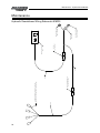
1
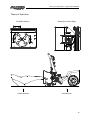
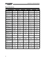
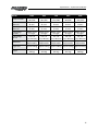
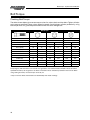
Operator and Parts Manual
Hydraulic Snowblower
Model 6025, 7225, 7235, 8425, & 8435
012013
FK378
Table of Contents - Hydraulic Snowblower
Table of Contents
Introduction..................................................................................................................................4
Safety.............................................................................................................................................5
• Safety.................................................................................................................................5
• General Safety...................................................................................................................6
• Start-up Safety..................................................................................................................6
• Operation Safety...............................................................................................................6
• Transport Safety................................................................................................................7
• Service and Maintenance Safety.....................................................................................7
• Storage Safety...................................................................................................................7
• Safety Signs......................................................................................................................8
• Safety Sign Installation....................................................................................................8
Assembly.....................................................................................................................................10
• Assembly Instructions....................................................................................................10
Start-up and Operation Instructions.........................................................................................12
• Theory of Operation.......................................................................................................13
Specifications..............................................................................................................................14
Bolt Torque..................................................................................................................................16
• Checking Bolt Torque......................................................................................................16
Troubleshooting..........................................................................................................................17
Parts Drawings............................................................................................................................18
• Hydraulic Snowblower Drawing - All Models..............................................................18
• Hydraulic Snowblower Parts List - All Models.............................................................20
• Hose Assembly - Model 60" SF......................................................................................22
• Hose Assembly - Model 72" SF......................................................................................23
• Hose Assembly - Model 72" HF......................................................................................24
• Hose Assembly - Model 84" SF......................................................................................25
• Hose Assembly - Model 84" HF......................................................................................26
• Manifold...........................................................................................................................28
Shipping Kit and Bundle Numbers...........................................................................................30
Hole Locations for Width Extendor Kits...................................................................................31
Maintenance...............................................................................................................................32
Hydraulic Snowblower Wiring Schematic 816225 - Optional.................................................32
Pictorial References....................................................................................................................34
Warranty......................................................................................................................................36
Manufacturer’s statement: for technical reasons Buhler Industries Inc. reserves the right to modify
machinery design and specifications provided herein without any preliminary notice.
Information provided herein is of descriptive nature. Performance quality may depend on soil fertility,
applied agricultural techniques, weather conditions and other factors.
3
Introduction - Hydraulic Snowblower
Introduction
For more than a generation, Allied has been building the most popular snowblowers used on
farms, airports, and municipalities throughout the North American snow-belt. Now, all that
experience brings you the rugged hydraulic snowblowers to handle more demanding snow
clearing jobs.
The Allied Hydraulic Snowblower is offered in three main sizes: 60", 72" and 84". The 72" and 84"
sizes are also made available in a higher capacity version for use on equipment with high flow
hydraulic systems. These models are best suited for the more demanding snow clearing jobs with
their increased cutting height, larger diameter auger and fan, and increased throwing capacity. As
an option, standard flow (SF) and high flow (HF) width extension kits are offered to increase the
cutting width of any model by 6" (15.2 cm).
The rugged design of the Allied Hydraulic Snowblower is meant to provide many years of
trouble-free operation. The direct drive auger and fan means there are no drive chains, U-joints,
or driveshafts in key areas that need lubrication, adjusting, or replacing. The cutting edge and
skid shoes provide for simple bolt on replacements. The hydraulic system is designed for efficient
operation without requiring any adjustments, provided that a 20.7 GPM flow rate is supplied at
3300 psi for SF models, and a 37 GPM flow rate is supplied at 3300 psi for HF models. The remote
in-cab control with supplied wiring harness allows the operator to conveniently control the snow
discharge path during operation.
Keep this manual handy for frequent reference. All new operators or owners must review the
manual before using the equipment and at least annually thereafter. Contact your Allied Dealer
if you need assistance, information, or additional copies of the manual. Visit our website at
www.farm-king.com for a complete list of dealers in your area.
The directions left, right, front and rear, as mentioned throughout this manual, are as seen facing
in the direction of travel of the implement.
4
Safety - Hydraulic Snowblower
Safety
Safety Instructions
Remember, YOU are the key to safety. Good safety practices not only protect you, but also the
people around you. Make these practices a working part of your safety program. Be certain that
everyone operating this equipment is familiar with the recommended operating and maintenance
procedures and follows all the safety precautions. Most accidents can be prevented. Do not risk
injury or death by ignoring good safety practices.
The alert symbol is used throughout this manual. It indicates attention is required and identifies
hazards. Follow the recommended precautions.
The safety alert symbol means…
ATTENTION! BECOME ALERT! YOUR SAFETY IS INVOLVED!
Caution
The caution symbol indicates a potentially hazardous situation
that, if not avoided, may result in minor or moderate injury. It
may also be used to alert against unsafe practices.
Warning
The Warning Symbol indicates a potentially hazardous situation
that, if not avoided, could result in death or serious injury, and
includes hazards that are exposed when guards are removed. It
may also be used to alert against unsafe practices.
Danger
The Danger Symbol indicates an imminently hazardous situation
that, if not avoided will result in death or serious injury. This
signal word is to be limited to the most extreme situations,
typically for machine components that, for functional purposes,
cannot be guarded.
5
Safety - Hydraulic Snowblower
General Safety Instructions
• Have a first-aid kit available for use and know how to use it.
• Have a fire extinguisher available, stored in a highly visible location, and know how to use it.
• Wear appropriate protective gear. This list may include but is not limited to:
-- hard hat
-- protective shoes with slip resistant soles
-- protective glasses or goggles
-- heavy gloves
-- wet weather gear
-- hearing protection
-- respirator or filter mask
• Read and understand the Operator’s Manual and all safety signs before operating, servicing,
adjusting, repairing, or unplugging the equipment.
• Do not attempt any unauthorized modifications to your Allied by Farm King product as this
could affect function or safety, and could affect the life of the equipment.
• Never start or operate the snowblower except from the operator’s station on the power unit.
• Inspect and clean the working area before operating.
• Keep hands, feet, clothing, and hair away from moving parts.
• Ensure bystanders are clear of the area before operating.
Start-Up Safety
•
•
•
•
•
Do not let inexperienced operators or children run this equipment.
Place all tractor and machine controls in neutral before starting.
Operate only with ROPS and seatbelt equipped tractors.
Do not operate inside a building unless there is adequate ventilation.
Ensure all shields are in place and in good condition before operating.
Operation Safety
•
•
•
•
•
•
6
Do not permit riders.
Do not wear loose fitting clothing during operation.
Do not allow anyone other than the operator close to the auger when in operation.
Stay clear of snowblower augers.
Stay clear of snowblower discharge chute. Rocks or debris can be picked up and thrown.
Never operate equipment in the raised position.
Safety - Hydraulic Snowblower
Transport Safety
• Review Transport Safety instructions in tractor manual before moving.
• Check with local authorities regarding transport on public roads. Obey all applicable laws
and regulations.
• Make sure the SMV (Slow Moving Vehicle) emblem and all the lights and reflectors that are
required by the local highway and transport authorities are in place, are clean, and can be
seen clearly by all overtaking and oncoming traffic.
• Never have the equipment in operation during transport.
• Always travel at a safe speed.
Service and Maintenance Safety
• Stop engine, set brake, remove ignition key, and wait for all moving parts to stop before
servicing, adjusting, repairing, or unplugging.
• Support the equipment with blocks or safety stands before working beneath it.
• Follow good shop practices including:
-- keep service area clean and dry
-- be sure electrical outlets and tools are properly grounded
-- use adequate light for the job.
• Use only tools, jacks, and hoists of sufficient capacity for the job.
• Replace and secure all shields removed during servicing before operating.
• Use heavy leather gloves to handle sharp objects.
• Check hydraulics regularly for leaks. Use cardboard to look for leaks, and use hand and eye
protection.
• Relieve pressure on hydraulic system before repairing or adjusting.
Storage Safety
• Store the unit in an area away from human activity.
• Do not permit children to play on or around the stored machine.
• Support the frame on stands and blocks to provide a secure base.
7
Safety - Hydraulic Snowblower
Safety Signs
• The following illustration shows the approximate location and detail of safety signs.
• Keep all safety signs clean and legible and replace any that are damaged or missing.
• When original parts are replaced, any safety signs affixed to those parts should be replaced
as well. Replacement safety signs are available from your local dealer using part number
shown in the corner of the sign.
SERIAL NUMBER
2
1
3
8
Safety - Hydraulic Snowblower
1
2
3
102893
9
Assembly - Hydraulic Snowblower
Assembly Instructions
1. Unpack all components and remove from shipping material. Verify quantities provided with
parts listing.
NOTE: Depending on your shipping/assembly configuration, steps 2-3 may already be
completed.
2. Begin with spout to snowblower assembly:
-- Place UHMV spout ring (815503) on top of spout base plate of snowblower fan housing.
-- Assemble spout retainer components (815506, 815507, 812364, 84048, 811791, 812363,
81570, 815508, 811795) to left hand set of holes according to the assembly views and
tighten all three bolts.
NOTE: Ensure bolts are placed facing upwards so that nuts and washers are on top or
damage to the snowblower will result.
NOTE: Avoid over tightening spout hardware. UHMW spout ring will deform/compress
from over torqued hardware (see Bolt Torque page) and cause binding in spout rotation.
-- Slip spout base into assembled spout retainer and align so that right hand set can be
assembled using similar technique. Ensure spout rotates freely once hardware is tightened.
-- Remove spout chain shield (815499) and install rotator chain (815496). Rotator motor
mounting holes are slotted to allow for installation and tightening of chain once connected.
Adjust position of sprocket (815497) on motor shaft so that sprocket is in line with chain tab
of spout. Adjust chain tightness and reattach chain shield.
3. Final hydraulic assembly
-- Attach deflector cylinder (24930M) to spout in direction shown in photo 10 and install
adaptors into ports of cylinder as well as deflector ports of hydraulic manifold. Attach
deflector hoses as shown in photo 10, ensuring bottom port of cylinder attached to bottom
port of manifold. Install hose retaining hardware and tighten hoses and hardware once
suitable routing is established. Spout may need to be rotated part way to the left during
hose routing and tightening so that hoses do not become excessively twisted during CCW
spout travel.
-- Install and tighten remaining two adaptors onto manifold.
-- Install and tighten male and female quick couplers to the straight ends of supply hoses and
connect elbow ends to adaptors just installed. The top port is system input and male-tipped
hose should be connected to this port for most applications. Orientate elbow ends to the
right, ensuring hose routings are free from points where damage may occur and tighten.
NOTE: Hoses will be looped rearwards at a later time as shown in photo 2.
10
Assembly - Hydraulic Snowblower
4. Universal Wiring Harness Installation (Optional): A three piece universal wiring harness
(816225) is provided to allow for quick and easy disconnects and hookups. The snowblower
segment is to be left permanently installed to snowblower and has a coupling that can be
connected/disconnected conveniently with main hydraulics. The cab harness segment is also
easily detachable so the spout control unit can be removed from the skid steer cab when not
needed. The main harness segment is designed to stay installed in skid steer while allowing
normal
use and maintenance of skid steer.
If snowblower is to be operated between two or more skid steer units, extra main harness
segments (816220, 816221) can be ordered and installed in each allowing quick change outs
between units.
Beginning at the engine compartment of the skid steer, identify a pathway where both
branches of the main harness can be safely routed. The snowblower harness branch should
usually follow the hydraulic lines running along the lift arm and a coupler should be located
next to main hydraulic disconnects. The cab control harness branch should usually follow the
routing of the skid steer main electrical harness and enter the cab in a suitable location (usually
in same area main harness enters cab). The coupler should be located in a convenient, but out
of the way, location somewhere within the cab.
NOTE: Skid steer cab will most likely need to be lifted into maintenance position to perform
this routing. Consult appropriate service personnel before proceeding.
When routing harness, keep all portions of harness away from points of wear, excessive heat,
and pinching areas. Use cable ties where required to keep harness secured to existing lines,
harnesses, or other retaining points. See photos 2 to 9 for a typical routing example. Coil up
any excess length of harness and secure in a suitable location in engine compartment (next to
battery for example, see photo 7). With battery ground terminal disconnected, connect positive
ring terminal of harness (end of fuse) to a switched or unswitched power source. Typical
examples may include battery post, auxiliary terminal post (if equipped) or hot terminal of
starter solenoid.
NOTE: Contact appropriate service personnel before making such connection.
Connect other ring terminal to a suitable ground location and reconnect battery ground strap.
Inside cab, place control box in a convenient location out of the way of other controls and
connect other end to coupling previously located inside cab from main harness. Coil up any
excess length in an out of the way location after routing harness appropriately.
On snowblower, remove manifold shield and connect snowblower harness segment in
arrangement shown in photo 1. Replace shield, making sure that harness exits freely through
recess in shield. Harness should then be cable tied to one of the main supply hoses for its
entire length. Install hose retainer loop onto one of shield retaining bolt locations using
3/8" x 1-1/4" bolt and 1-1/2" washer. Route supply hoses through it towards skid steer as
shown in photo 2. Arrangement may be changed to suit other applications.
NOTE: Spout controls may behave erratically until hydraulic system is primed.
11
Start-up and Operation - Hydraulic Snowblower
Start-up and Operation Instructions
The hydraulic system of the snowblower is configured so that the fan motor is prevented from
stalling in a snow overload condition. A significant increase in fan loading increases the hydraulic
pressure drop across the fan motor, which in turn diverts flow away from the auger motor, thereby
reducing/stopping further fan loading and simultaneously providing more power to clear the fan.
When the fan clears and pressure returns to normal, flow returns to auger so normal operation can
proceed. The fan should not require unclogging, other than a situation where a rock or other hard
material becomes jammed in it.
Depth of cut at ground level can be controlled both by tilting the snowblower forward/rearward
and by using one of the three desired height sets of the skids. If it is preferred that the skids not be
used to control cut depth, a fourth set of holes are provided (skid in highest position) but use is not
recommended due to the premature cutting edge wear that may result. Snowblower should not be
operated with skids completely removed as damage to housing may result.
Each season, the chute rotator chain should be lubricated and checked for excess slack (chain can
be tightened by taking advantage of the mounting motor slots). Also, the right hand auger bearing
should be greased each season and every 10 hours of use thereafter. Run the snowblower at low
RPM to check all operation before blowing snow. Periodically check bolt tightnesses, particularly
the fan motor and auger motor housing bolts.
Always disengage hydraulics and shut off the power unit before doing any servicing or
unplugging. When replacing bearings or tightening a loose bearing collar, always tighten collar in
the direction of shaft rotation using a center punch or a similar tool.
If the fan should need to be removed, use an appropriate two jaw puller using the slots provided
in the fan and fan housing backplate. Prior to reassembly, tapered surfaces need to be completely
clean (no paint or rust) with a coating of anti-seize compound applied. Castle nut must be torqued
to at least 140 ft-lbs and aligned such that the nut can then be retained with new cotter-pin.
If auger motor is removed from auger, its surfaces should also be cleaned and coated with antiseize compound before re-assembly.
Caution
12
The locking pins must extend through the holes in the attachment
when mounting the snowblower to an implement. Levers must be
fully down and locked. Failure to secure pins can allow attachment
to come off and cause injury or death.
Start-up and Operation - Hydraulic Snowblower
Theory of Operation
Fan Blade Rotation
Rotate Spout Left or Right
Uncleared Snow
Cleared Snow
13
Specifications - Hydraulic Snowblower
Specifications
Model
6025
7225
7235
8425
8435
Width, overall
62"
(1575 mm)
74"
(1880 mm)
74"
(1880 mm)
86"
(2184 mm)
86"
(2184 mm)
Height, overall
62"
(1575 mm)
62"
(1575 mm)
67"
(1702 mm)
62"
(1575 mm)
67"
(1702 mm)
Depth
36"
(914 mm)
36"
(914 mm)
36"
(914 mm)
36"
(914 mm)
36"
(914 mm)
Height, intake
25"
(635 mm)
25"
(635 mm)
35"
(889 mm)
25"
(635 mm)
35"
(889 mm)
Width, intake
60"
(1524 mm)
72"
(1829 mm)
72"
(1829 mm)
84"
(2134 mm)
84"
(2134 mm)
Fan Depth,
in (mm)
6"
(152 mm)
6"
(152 mm)
6"
(152 mm)
6"
(152 mm)
6"
(152 mm)
Fan Diameter
20"
(508 mm)
20"
(508 mm)
24"
(607 mm)
20"
(508 mm)
24"
(607 mm)
Throwing
Distance
40'
(12.2 m)
40'
(12.2 m)
40'
(12.2 m)
40'
(12.2 m)
40'
(12.2 m)
Fan Tip Speed
60 mph
(96 kph)
60 mph
(96 kph)
71 mph
(114 kph)
60 mph
(96 kph)
71 mph
(114 kph)
Auger Diameter
14"
(356 mm)
14"
(356 mm)
18"
(457 mm)
14"
(356 mm)
18"
(457 mm)
Auger to Housing
Clearance
1"
(25 mm)
1"
(25 mm)
1"
(25 mm)
1"
(25 mm)
1"
(25 mm)
Flighting Pitch
10"
(254 mm)
10"
(254 mm)
10"
(254 mm)
10"
(254 mm)
10"
(254 mm)
270°
270°
270°
270°
270°
Hydraulic
Motor
Hydraulic
Motor
Hydraulic
Motor
Hydraulic
Motor
Hydraulic
Motor
Deflector Control
Range
16º below
grade to 73°
above grade
16º below
grade to 73°
above grade
16º below
grade to 73°
above grade
16º below
grade to 73°
above grade
16º below
grade to 73°
above grade
Deflector Control
Hydraulic
Cylinder
Hydraulic
Cylinder
Hydraulic
Cylinder
Hydraulic
Cylinder
Hydraulic
Cylinder
Hydraulic Type
Standard
Flow
Standard
Flow
High Flow
Standard
Flow
High Flow
Hydraulic Flow
20-23 GPM
(76 LPM)
20-23 GPM
(76 LPM)
20-40 GPM
(76 LPM)
20-23 GPM
(76 LPM)
20-40 GPM
(76 LPM)
Chute Rotation
Range
Chute Rotation
14
Specifications - Hydraulic Snowblower
Model
6025
7225
7235
8425
8435
23 GPM
(88 LPM)
23 GPM
(88 LPM)
40 GPM
(153 LPM)
23 GPM
(88 LPM)
40 GPM
(153 LPM)
Side Plate
Thickness
.25"
(6 mm)
.25"
(6 mm)
.25"
(6 mm)
.25"
(6 mm)
.25"
(6 mm)
Main Body
Thickness
.179"
(5 mm)
.179"
(5 mm)
.179"
(5 mm)
.179"
(5 mm)
.179"
(5 mm)
Cutting Edge
Location
Below center
of auger
Below center
of auger
Below center
of auger
Below center
of auger
Below center
of auger
Cutting Edge,
bolt on
1/2" x 4"
1/2" x 4"
1/2" x 4"
1/2" x 4"
1/2" x 4"
(13 x 102 mm) (13 x 102 mm) (13 x 102 mm) (13 x 102 mm) (13 x 102 mm)
Maximum Flow
Skid Shoes
Auger Tube
Weight
Adjustable/
Replaceable
Adjustable/
Replaceable
Adjustable/
Replaceable
Adjustable/
Replaceable
Adjustable/
Replaceable
Square Tubing Square Tubing Square Tubing Square Tubing Square Tubing
828 lb
(376 kg)
923 lb
(419 kg)
1084 lb
(491 kg)
951 lb
(431 kg)
1108 lb
(503 kg)
15
Bolt Torque - Hydraulic Snowblower
Bolt Torque
Checking Bolt Torque
The tables shown below give correct torque values for various bolts and hex bolts. Tighten all bolts
to the torques specified in chart unless otherwise noted. Check tightness of bolts periodically, using
bolt torque chart as a guide. Replace hardware with the same strength bolt.
Bolt Torque*
Bolt Diameter
Grade 2 Bolts
Grade 5 Bolts
Grade 8 Bolts
(inches)
SAE 2
SAE 5
SAE 8
“A”
(lb-ft)
(N.m)
(lb-ft)
(N.m)
(lb-ft)
(N.m)
0.25 (1/4)
6
8
9
12
12
17
0.313 (5/16)
10
13
19
25
27
36
0.375 (3/8)
20
27
33
45
45
63
0.438 (7/16)
30
42
53
72
75
100
0.5 (1/2)
45
61
80
110
115
155
0.563 (9/16)
70
95
115
155
165
220
0.625 (5/8)
95
128
160
215
220
305
.75 (3/4)
165
225
290
390
400
540
0.875 (7/8)
170
230
420
570
650
880
1
225
345
630
850
970
1320
Torque figures indicated above are valid for non-greased or non-oiled threads and heads unless otherwise
specified. Therefore, do not grease or oil bolts or hex bolts unless otherwise specified in this manual. When
using locking elements, increase torque values by 5%.
* Torque value for bolts and hex bolts are identified by their head markings.
16
Troubleshooting - Hydraulic Snowblower
Troubleshooting
Symptom
Probable Cause
Remedy
Nothing works
• Hydraulic valve not engaged • Engage to full detent
• One or more quick couplers • Fully engage all couplers
not completely engaged
• Incorrect flow direction
• Switch flow direction using
controls or swapping hose
ends
• Defective quick coupler
• Replace defective quick
couplers
• Hydraulic pump low on fluid • Top up fluid level
Fan turns too slow
• Inadequate hydraulic flow
for snowblower
• Check the gpm of your
system, ensure auxilliary
pumps is engaged on power
unit for high flow models
Fan and auger work but chute
controls do not work properly
• Electrical connections to
battery
• Fuse blown
• Connector from switches to
harness not connecting
• Air in hydraulic system
• Ensure that the clamps are
making proper connection
• Replace fuse
• Ensure the connector is fully
engaged. Check for broken
wires.
• Check fluid level of power
unit, purge air
• Check specifications and
flow setting
• Insufficient hydraulic power
Chute rotation seems to lack
power to turn.
• Broken/disconnected chain
• Check chain condition
• Debris/ice caught in chain
• Clear chute and chain of
obstructions
• Chute retainer hardware too
tight
• Loosen hardware so that
chute can be turned by hand
with chain disconnected
Fan stops/slows when raising
or turning skid steer
• Insufficient hydraulic power
• Check that operating at full
engine RPM
• Check flow rate and PSI w/
requirements
Skid steer unable to lift
snowblower
• Size mismatch of
snowblower vs. skid steer
• Match lifting capacity of
skid steer with weight of
snowblower plus snow load
Chute controls operate
backwards
• Control box mounted in
wrong orientation
• Wiring connected
improperly on valve
manifold
• Mount in appropriate
orientation (if not possible,
connections may be
swapped underneath
manifold cover
One control switch operates
two different chute functions
• Wires connected improperly • Connect wires in proper
on valve manifold
arrangement
17
18
2
4
8
8
13
2
37
39
50
5
37
39
40
1
7
22
21
1
22
1
55
1
9
4
10
4
47
4
42
2
17
1
30
10
37
39
7
22
24
1
8
8
51
4
39
1
39
1
39
1
39
1
19
1
15
2
14
2
Parts - Hydraulic Snowblower
Hydraulic Snowblower - All Models
Parts - Hydraulic Snowblower
53
2
1
1
18
1
6
6
3
4
33
4
2
4
16
1
37
39
45
14
37
39
7
22
37
39
4
4
42
1
37
39
61
5
38
1
50
5
32
2
43
2
49
2
31
2
23
4
23
4
5
2
28
1
29
1
46
7
34
5
52
1
7
22
34
5
6
6
58
2
6
6
12
2
37
39
41
1
46
7
61
5
25
8
8
27
1
35
8
26
1
46
7
54
1
37
39
56
2
14
2
11
6
59
2
58
2
20
2
44
6
45
14
45
14
48
6
60
2
59
2
60
2
USED ON SF
MODELS ONLY
USED ON HF
MODELS ONLY
19
Parts - Hydraulic Snowblower
When Ordering Parts
Always give your dealer the Model, Color and Serial Number of your machine to assist them in
ordering and obtaining the correct parts. Use the exploded view and tabular listing of the area of
interest to exactly identify the required part.
Item
Part Number
1
24930M
Cyl 1.75 Dia x 5.0 9/16 Orb
1
2
811791
Bolt Hex 0.500Nc x 2.0 Gr5 (Pl)
4
3
811795
Bolt Hex 0.375Nc x 2.00 Gr5 (Pl)
4
4
812259
Bolt Hex 0.375Nc x 5.50 Gr5 (Pl)
4
Qty
5
812026
5/16" x 1" Hex Bolt (Pl)
2
6
812086
Adaptor Str 9/16 Morb x 9/16 Mjic
6
7
812363
Nut Lock (Steel) 0.375 Grb (Pl)
22
8
812364
Nut Lock (Steel) 0.500Nc Grb (Pl)
8
9
812482
Nut Lock (Steel) 0.625Nc Grb (Pl)
4
10
812639
Washer 0.625 SAE Flat Bs (Pl)
4
11
812661
Adaptor Str 1-1/16 Morb x 1-1/6 Mjic
6
12
812723
Adaptor Str 7/8 Mjic x 7/8 Morb
2
13
812734
Elbow 90 7/8 Morb x 7/8 Mjic
2
14
812838
Adaptor Str 7/16 Morb x 9/16 Mjic
2
15
813208
Adaptor Str 1-1/16 Mjic x 7/8 Morb
2
16
813581
Washer Flat 1.5 x 0.531 x 0.25 (Pl)
1
17
815538
60" SF Hyd Sb Main Housing Weldt
1
815438
72" SF Hyd Sb Main Housing Weldt
1
815963
72" HF Hyd Sb Main Housing Weldt
1
815942
84" SF Hyd Sb Main Housing Weldt
1
815953
84" HF Hyd Sb Main Housing Weldt
1
18
815439
Hyd SB Spout Weldt
1
19
815440
Hydraulic SB Fan Weldt - SF Models
1
815527
Hydraulic SB Fan Weldt - HF Models
1
815441
Hyd SB Skid Shoe Weldt
2
20
21
815444
Hyd SB Auger Motor Mount
1
22
815541
60" Hyd SB Auger Weldt
1
815445
72" SF Hyd SB Auger Weldt
1
815530
72" HF Hyd SB Auger Weldt
1
815946
84" SF Hyd SB Auger Weldt
1
815957
84" HF Hyd SB Auger Weldt
1
23
81546
Washer 0.313 Flat Std Hs (Pl)
4
24
815939
60" Snowblower Cutting Edge
1
815495
72" Snowblower Cutting Edge
1
815951
84" Snowblower Cutting Edge
1
815496
Hyd SB Spout Chain
1
25
20
Description
Parts - Hydraulic Snowblower
Item
Part Number
Description
Qty
26
815497
19T 1/2" Pitch Spout Rotation Sprocket
1
27
815498
Hydraulic Manifold - Shield
1
28
815499
Spout Rotation Motor - Shield
1
29
815503
UHMW Spout Ring
1
30
815505
Flat Head Socket Cap 3/8-16 x 1.25
10
31
815506
Snowblower Spout Spacer
2
32
815507
Snowblower Spout Clamp
2
33
815508
Spout Bushing
4
34
81925
Hex Bolt 5/16" x 1-34" (Pl)
5
35
815608
Block Polypropelene 3/8 Pair
4
37
81570
Washer 0.375 Flat St Hs (Pl)
39
38
816041
Hyd SB SF Manifold (Comatrol)
1
816376
Hyd SB HF Manifold (Comatrol)
1
816042
Hydraulic Snowblower - SF Fan Motor
1
816043
Hydraulic Snowblower - HF Fan Motor
1
816044
Hyd SB SF/HF Auger Motor
1
39
40
41
816045
Hyd SB SF/HF Spout Motor
1
42
816054
5/8" Block Polypropelene Pair
1
43
816057
Adaptor Str 10 Morb x 6 Mjic
2
44
81966
Nut Lock (Nylon) 0.500Nc (Pl)
6
45
84048
Washer 0.500 Flat SAE Bs (Pl)
14
46
84072
3/8" x 3/4" Hex Bolt (Pl)
7
47
84270
Bolt Hex 0.625 x 1.75 Gr5 (Pl)
4
48
84277
Bolt Hex 0.500Nc x 1.50 Gr5 (Pl)
6
49
84541
Lock Nut (Nylon) 0.313 Nc
2
50
86171
Bolt Hex 0.375 Nc x 1.25
5
51
87553
Bolt Hex 0.500Nc x 1.75 Gr5 (Pl)
4
52
909277
Manual Holder 3.5" Dia.
1
53
961876
1/2" x 1-1/2" Clev Pin (Pl)
2
54
966314
Hydraulic Hose Holder
1
55
968632
Housing w/ Brg 4-Bolt Ti F208
1
56
9812430
Cotter Pin 0.125 x 1.00 (Pl)
2
57
981309
1/8" x 1-1/4" Cotter Pin (Br)
1
58
816052
3/4 Block Polypropelene Pair
1
59
816051
3/4 Hose Clamp Cover Plate
1
60
810640
Hex Bolt 0.313 Unc x 2.00
1
61
29256
Cover Plate
1
21
Parts - Hydraulic Snowblower
Hose Assembly - Model 60" SF
Part Number Description
816191
Hose 3/8 x 66 9/16 Fjic x 9/16 F90
816206
Hose 3/4 x 23.8 1-16 Fjic Jic 45
816207
Hose 3/4 x 27.3 1-1/16 Fjic x 45
816208
Hose 5/8 x 25 7/8 Fjic x 7/8 Jic 45
816209
Hose 3/8 x 23-9/16 Fjic x Jic 45
816212
Hose 3/8 x 39 9/16 Fjic 90
816452
Hyd SB Main Return Hose
816189
1/2" Body, Male FF Coupler
816453
Hose 3/4 x 91.3 1-1/16 Morb x Jic
816454
Hyd Main Pressure Hose
816190
1/2" Body, Female FF Coupler
816453
Hose 3/4 x 91.3 1-1/16 Morb x Jic
22
Parts - Hydraulic Snowblower
Hose Assembly - Model 72" SF
Part Number Description
816191
Hose 3/8 x 66 9/16 Fjic x 9/16 F90
816206
Hose 3/4 x 23.8 1-16 Fjic Jic 45
816207
Hose 3/4 x 27.3 1-1/16 Fjic x 45
816209
Hose 3/8 x 23 9/16 Fjic x Jic 45
816211
Hose 5/8 x 29.5 7/8 Swfjic 45
816212
Hose 3/8 x 39-9/16 Fjic 90
816452
Hyd SB Main Return Hose
816189
1/2" Body, Male FF Coupler
816453
Hose 3/4 x 91.3 1-1/16 Morb x Jic
816454
Hyd Main Pressure Hose
816190
1/2" Body, Female FF Coupler
816453
Hose 3/4 x 91.3 1-1/16 Morb x Jic
23
Parts - Hydraulic Snowblower
Hose Assembly - Model 72" HF
Part Number Description
816059
Hose 3/8 x 43.4 9/16 Fjic 45
816060
Hose 5/8 x 32 7/8 Fjic x 7/8 Jic 45
816061
Hose 3/8 x 27.7 9/16 Fjic x Jic 45
816191
Hose 3/8 x 66 9/16 Fjic x 9/16 F90
816214
Hyd SB Main Return Hose
816189
1/2" Body, Male FF Coupler
816210
Hose 3/4 x 87 1-1/16 Morb x Jic 45
816215
Hose 3/4 x 30.5 1-1/16 Morb x Jic 45
816216
Hose 3/4 x 31.5 1-1/16 Morb x Jic 45
816219
Hyd Main Pressure Hose
816190
1/2" Body, Female FF Coupler
816210
Hose 3/4 x 87 1-1/16 Morb x Jic 45
24
Parts - Hydraulic Snowblower
Hose Assembly - Model 84" SF
Part Number Description
816191
Hose 3/8 x 66 9/16 Fjic x 9/16 F90
816206
Hose 3/4 x 23.8 1-16 Fjic Jic 45
816207
Hose 3/4 x 27.3 1-1/16 Fjic x 45
816209
Hose 3/8 x 23 9/16 Fjic x Jic 45
816212
Hose 3/8 x 39 9/16 Fjic 90
816213
Hose 5/8 x 33.5 7/8 Swfjic 45
816452
Hyd SB Main Return Hose
816189
1/2" Body, Male FF Coupler
816453
Hose 3/4 x 91.3 1-1/16 Morb x Jic
816454
Hyd Main Pressure Hose
816190
1/2" Body, Female FF Coupler
816453
Hose 3/4 x 91.3 1-1/16 Morb x Jic
25
Parts - Hydraulic Snowblower
Hose Assembly - Model 84" HF
Part Number Description
816059
Hose 3/8 x 43.4 9/16 Fjic 45
816061
Hose 3/8 x 27.7 9/16 Fjic x Jic 45
816191
Hose 3/8 x 66 9/16 Fjic x 9/16 F90
816214
Hyd SB Main Return Hose
816189
1/2" Body, Male FF Coupler
816210
Hose 3/4 x 87 1-1/16 Morb x Jic 45
816215
Hose 3/4 x 30.5 1-1/16 Morb x Jic 45
816216
Hose 3/4 x 31.5 1-1/16 Morb x Jic 45
816217
Hose 5/8 x 37 7/8 Swfjic 45
816219
Hyd Main Pressure Hose
816190
1/2" Body, Female FF Coupler
816210
Hose 3/4 x 87 1-1/16 Morb x Jic 45
26
Parts - Hydraulic Snowblower
Manifold
28
Parts - Hydraulic Snowblower
Item
1
2
3
4
5
6
7
8
9
Part Number Description
816420
Plug - Right
X3929
Seal Kit
816421
Relief Valve - High Flow
816534
Relief Valve - Standard Flow
X3930
Seal Kit
816422
Plug - Top Right
X3930
Seal Kit
816423
Plug - Left Front
X3932
Seal Kit
816424
Plug - Left Rear
X3933
Seal Kit
816425
Plug - Front
X3932
Seal Kit
816426
Plug - Top Left
X3935
Seal Kit
816427
Solenoid
X3934
Seal Kit
816428
Coil
816429
Coil Nut
816430
Plug - Top Front
X3931
Seal Kit
29
Shipping Kit and Bundle Numbers - Hydraulic Snowblower
Shipping Kit and Bundle Numbers
Bundle Number Description
Qty
60" Standard Flow - Hydraulic Snowblower (HSB6025SF)
F1534
Full Assembly w/ Hoses
1
72" Standard Flow - Hydraulic Snowblower (HSB7225SF)
F1535
Full Assembly w/ Hoses
1
84" Standard Flow - Hydraulic Snowblower (HSB8425SF)
F1537
Full Assembly w/ Hoses
1
72" High Flow - Hydraulic Snowblower (HSB7235HF)
F1536
Full Assembly w/ Hoses
1
84" High Flow - Hydraulic Snowblower (HSB8435HF)
F1538
Full Assembly w/ Hoses
1
Optional Bundle Numbers
The following is a list of options available for the Kits listed above.
Part Number Description
Qty
X3926
SF Width Extender Kit
1
X3927
HF Width Extender Kit
1
816225
Universal Skid Steer Wiring Harness
1
816464
Bobcat 14 Pin Wire Harness
1
816465
John Deere 14 Pin Wire Harness
1
816466
CAT “B” Series and “C” Series 8 Pin Wire Harness
1
816479
Case "Alpha" Series 14 Pin Wire Harness
1
816513
CAT “B” Series 14 Pin SF Wire Harness
1
816514
CAT “B” Series 14 Pin HF Wire Harness
1
30
Hole Locations for Width Extendor Kits - Hydraulic Snowblower
Hole Locations for Width Extendor Kits
STANDARD FLOW WIDTH
HIGH FLOW WIDTH
CENTER OF HOLE IS
FLUSH WITH SURFACE
3.64
6.25
6.25
0.53
5X
6.25
6.25
0.53
4X
6.25
6.25
6.25
1.75
4X
1.75
5X
1
1
2
1
2
1
3
1
Item
Part Number
1
84277
Bolt Hex 0.500 Nc x 1.50 Gr5 (Pl)
Description
2
84048
Washer 0.500 Flat SAE Bs (Pl)
3
81966
Nut Lock (Nylon) 0.500 Nc (Pl)
31
32
816224
816220
QUICK DISCONNECT AT
HYDRAULIC ENDS
SNOWBLOWER MANIFOLD HOOKUPS
(SEE PHOTO 9 FOR PROPER CONNECTING)
816221
IN CAB
DISCONNECT
REMOTE CONTROL
BOX
POSITIVE BATTERY
RING TERMINAL
INLINE FUSE
HOLDER
NEGATIVE BATTERY
RING TERMINAL
+
-
Maintenance - Hydraulic Snowblower
Maintenance
Hydraulic Snowblower Wiring Schematic 816225
Maintenance - Hydraulic Snowblower
Part Number
Description
816049
Electric Switch Housing - Base
816050
Electric Switch Housing - Top
816220
Hyd SB Harness, Cab
816221
Hyd SB Harness, Battery
816222
Hyd SB Harness, Valve
816223
Eaton Switch - Left & Right
816224
Eaton Switch - Up & Down
816226
3-3/16" Steel Encased Magnet
33
Pictorial References - Hydraulic Snowblower
Pictorial References
Harness secured to hydraulic hose
1
2
Manifold Hookups
Harness
Top view of snowblower connections
Harness routed with existing
hydraulic lines on lift arm
Coupler
3
4
Main harness routing
Main harness routing
5
34
Main harness routing
Pictorial References - Hydraulic Snowblower
Main harness routing (cab lifted)
Negative
Positive
Extra length coiled
7
Main Harness power connections
Coupler located behind operator station
6
Harness follows existing cab harness
Coupler from main harness
Extra length coiled
8
9
In-cab harness routing
Control Box
In-cab harness routing
10
Chute hydraulic hook-ups
35
Warranty - Hydraulic Snowblower
Allied by Farm King Limited Warranty
This document limits your warranty rights.
Base Limited Warranty
Buhler Industries Inc. provides this warranty only to original retail purchasers of its product.
Buhler Industries Inc. warrants to such purchasers that all Buhler Industries Inc. manufactured
parts and components used and serviced as provided for in the Operator’s Manual shall be free
from defects in materials and workmanship for a period following delivery to the original retail
purchaser of 12 months (80 days for commercial applications). This limited warranty applies only
to those parts and components manufactured by Buhler Industries Inc. Parts and components
manufactured by others are subject to their manufacturer’s warranties, if any.
Buhler Industries Inc. will fulfill this limited warranty by, at its option, repairing or replacing
any covered part that is defective or is the result of improper workmanship, provided that the
part is returned to Buhler Industries Inc. within thirty (30) days of the date that such defect or
improper workmanship is, or should have been, discovered. Buhler Industries Inc. reserves the
right to either inspect the product at the buyer’s location or have it returned to the factory for
inspection. Parts must be returned through the selling representative and the buyer must prepay
transportation charges.
Buhler Industries Inc. will not be responsible for repairs or replacements that are necessitated,
in whole or part, by the use of parts not manufactured by or obtained from Buhler Industries Inc.
Under no circumstances are component parts warranted against normal wear and tear. There
is no warranty on product pump seals, product pump bearings, rubber product hoses, pressure
gauges, or other components that require replacement as part of normal maintenance. Also:
Buckets and Bucket Tines carry no warranty, Bent Spears carry no warranty, Snowblower Fan
Shafts carry no warranty, Mower Blades carry no warranty, Portable Auger Parts Have Two (2)
Year Warranty, Loader Parts Have Two (2) Year Warranty. The purchaser is solely responsible for
determining suitability of goods sold. This warranty is expressly in lieu of all other warranties
expressed or implied. Buhler Industries Inc. will in no event be liable for any incidental or
consequential damages whatsoever. Nor for any sum in excess of the price received for the
goods for which liability is claimed.
Repair Parts Limited Warranty
Buhler Industries Inc. warrants Farm King replacement parts purchased after the expiration of the
Buhler Industries Inc. Limited Warranty, and used and serviced as provided for in the Operator’s
Manual, to be free from defects in materials or workmanship for a period of thirty (30) days
from the invoice date for the parts. Buhler Industries Inc. will fulfill this limited warranty by, at
its option, repairing or replacing any covered part that is defective or is the result of improper
workmanship, provided that the part is returned to Buhler Industries Inc. within thirty (30) days
of the date that such defect or improper workmanship is, or should have been, discovered. Such
parts must be shipped to Buhler Industries Inc. at the purchaser’s expense.
What is Not Covered
Under no circumstances does this limited warranty cover any components or parts that have
been subject to the following: negligence; alteration or modification not approved by Buhler
Industries Inc.; misuse; improper storage; lack of reasonable and proper maintenance, service,
or repair; normal wear; damage from failure to follow operating instructions; accident; and/
or repairs that have been made with parts other than those manufactured, supplied, and or
authorized by Buhler Industries Inc.
36
Warranty - Hydraulic Snowblower
Authorized Dealer and Labor Costs
Repairs eligible for labor under this limited warranty must be made by Buhler Industries Inc. or an
authorized Farm King dealer. Buhler Industries Inc. retains the exclusive discretion to determine
whether it will pay labor costs for warranty repairs or replacements, and the amount of such
costs that it will pay and the time in which the repairs will be made. If Buhler Industries Inc.
determines that it will pay labor costs for warranty work, it will do so by issuing a credit to the
dealer’s or distributor’s account. Buhler Industries Inc. will not approve or pay invoices sent for
repairs that Buhler Industries Inc. has not previously approved. Warranty service does not extend
the original term of this limited warranty.
Warranty Requirements
To be covered by warranty, each Farm King new product must be registered with Buhler
Industries Inc. within thirty (30) days of delivery to original retail purchaser. If the customer
decides to purchase replacement components before the warranty disposition of such
components is determined, Buhler Industries Inc. will bill the customer for such components and
then credit the replacement invoice for those components later determined to be covered by this
limited warranty. Any such replacement components that are determined not be covered by this
limited warranty will be subject to the terms of the invoice and shall be paid for by the purchaser.
Warranty Claims:
Warranty requests must be prepared on Buhler Industries Inc. Warranty Claim Forms with all
requested information properly completed. Warranty Claims must be submitted within a thirty
(30) day period from date of failure repair.
Warranty Labor:
Any labor subject to warranty must be authorized by Buhler Industries Inc. The labor rate for
replacing defective parts, where applicable, will be credited at 100% of the dealer’s posted shop
rate.
Exclusive Effect of Warranty and Limitation of Liability
TO THE EXTENT PERMITTED BY LAW, Buhler Industries Inc. DISCLAIMS ANY
WARRANTIES, REPRESENTATIONS, OR PROMISES, EXPRESS OR IMPLIED, AS TO THE QUALITY,
PERFORMANCE, OR FREEDOM FROM DEFECT OF THE COMPONENTS AND PARTS COVERED BY
THIS WARRANTY AND NOT SPECIFICALLY PROVIDED FOR HEREIN.
TO THE EXTENT PERMITTED BY LAW, Buhler Industries Inc. DISCLAIMS ANY IMPLIED
WARRANTIES OF MERCHANTABILITY AND FITNESS FOR A PARTICULAR PURPOSE ON ITS
PRODUCTS COVERED HEREIN, AND DISCLAIMS ANY RELIANCE BY THE PURCHASER ON
Buhler Industries Inc.’S SKILL OR JUDGMENT TO SELECT OR FURNISH GOODS FOR ANY
PARTICULAR PURPOSE. THE PURCHASER’S ONLY AND EXCLUSIVE REMEDIES IN CONNECTION
WITH THE BREACH OR PERFORMANCE OF ANY WARRANTY ON ProductS manufactured
by Buhler Industries Inc. ARE THOSE SET FORTH HEREIN. IN NO EVENT SHALL Buhler
Industries Inc. BE LIABLE FOR INCIDENTAL OR CONSEQUENTIAL DAMAGES (INCLUDING,
BY WAY OF EXAMPLE ONLY AND NOT LIMITATION, LOSS OF CROPS, LOSS OF PROFITS OR
REVENUE, OTHER COMMERCIAL LOSSES, INCONVENIENCE, OR COST OF REPLACEMENT
OF RENTAL EQUIPMENT). IN NO EVENT SHALL FARM KING’S CONTRACT OR WARRANTY
LIABILITY EXCEED THE PURCHASE PRICE OF THE PRODUCT.
37
Warranty - Hydraulic Snowblower
(Note that some provinces or states do not allow limitations on how long an implied warranty
lasts or the exclusion or limitation of incidental or consequential damages, so the above
limitations and exclusion may not apply to you.) This warranty gives you specific legal rights and
you may also have other rights, which vary from province to province or state to state.
Buhler Industries Inc. neither assumes nor authorizes any person or entity, including its selling
representatives, to assume any other obligations or liability in connections with the sale of
covered equipment, or to make any other warranties, representations, or promises, express or
implied, as to the quality, performance, or freedom from defect of the components and parts
covered herein. No one is authorized to alter, modify, or enlarge this limited warranty, or its
exclusions, limitations and reservations.
Corrections of defects and improper workmanship in the manner, and for the applicable time
periods, provided for herein shall constitute fulfillment of all responsibilities of Buhler Industries
Inc. to the purchaser, and Buhler Industries Inc. shall not be liable in negligence, contract, or on
any other basis with respect to the subject equipment.
This limited warranty is subject to any existing conditions of supply which may directly affect
Buhler Industries Inc.’s ability to obtain materials or manufacture replacement parts.
Buhler Industries Inc. reserves the right to make improvements in design or changes in
specifications to its products at anytime, without incurring any obligation to owners of units
previously sold.
Government Legislation:
Warranty terms and conditions are subject to provincial or state legislation.
Important Note: This warranty does not apply to rentals.
38
www.farm-king.com
1330 43rd Street NW
Fargo, ND USA 58102
Ph.: 701.282.7014 | Fax: 701.282.5865
Toll Free: 888.524.1004
E-mail: [email protected]
www.farm-king.com
Equipment shown is subject to change without notice.
©2013 Buhler Trading Inc. Printed in USA. TSX:BUI
a division of Buhler Industries Inc.