1
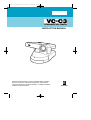
*VC-C3/E/US/QX3.32
5/29/01
3:26 PM
Page 1
INSTRUCTION MANUAL
Please read this instruction manual carefully before operation.
Be sure to read the “Safe Use of Equipment” section before
using this equipment. Store this manual in a readily accessible
location for future reference.
E
ENGLISH
*VC-C3/E/US/QX3.32
5/29/01
3:26 PM
Page 2
Introduction
Thank you for purchasing the Canon Communication Camera VC-C3.
Read this Instruction Manual carefully to ensure that you use the VC-C3 correctly and
safely. Read the “Safe Use of Equipment” section first and obser ve these instructions
when you use the VC-C3.
Features
■
■
■
■
■
■
1/4 inch CCD, 410,000 pixels for high-quality images
High-performance 10 power zoom
Wide angle photographic range
High-speed precision camera head movement
Preset function (programmable presets can be stored in camera’s memory)
Camera ID setting
If the VC-C3 is connected to a recording device (for example a VCR), Canon Inc.
accepts no responsibility whatsoever for any financial losses that may be incurred as a
result of the loss of recorded information or images, regardless of the internal or
external cause of the loss.
Copyright Information
Video or still images recorded using your VC-C3 cannot be used in ways that infringe
copyright laws or without the consent of the owner, unless intended for personal use
only.
Icons Used in This Instruction Manual
Indicates important information that must be observed or actions that are
prohibited during an operation.These notes must be read to prevent
possible faults or damage to the VC-C3.
Indicates supplementary information or a reference to an operation.
Users are advised to read these memos.
Notes
1.
2.
3.
4.
The unauthorized transfer of all or any part of the contents of this Manual is
forbidden.
The contents of this Manual are subject to change without notice.
Every effort has been made to ensure that this Manual is flawless. However, if you
find any oversights, please let us know.
Item 3. notwithstanding, Canon accepts no responsibility for any effects resulting
from the use of this Manual.
CANON and the CANON logo are registered trademarks of Canon Inc. Other names
of products and companies mentioned in this Manual are trademarks or registered
trademarks of the respective companies.
2
*VC-C3/E/US/QX3.32
5/29/01
3:26 PM
Page 3
Safe Use of Equipment
An exclamation point, within a triangle, is intended to alert the user to the
presence of important operating and maintenance (servicing) instructions
in the literature accompanying the product.
Important Warnings
CAUTION:
TO REDUCE THE RISK OF ELECTRIC SHOCK, DO NOT REMOVE
COVER (OR BACK). NO USER-SERVICEABLE PARTS INSIDE. REFER
SERVICING TO QUALIFIED SERVICE PERSONNEL.
The serial number of this equipment may be found on the back of the camera head.
No others have the same serial number as yours.
You should record the number and other vital information here and retain this book
as a permanent record of your purchase to aid identification in case of theft.
Date of Purchase
Dealer Purchased from
Dealer Address
Dealer Phone No.
Model No. VC-C3
Serial No.
Important Operational Instructions
WARNING:
TO REDUCE THE RISK OF ELECTRIC SHOCK, DO NOT EXPOSE THIS
EQUIPMENT TO RAIN OR MOISTURE.
CAUTION:
TO REDUCE THE RISK OF ELECTRIC SHOCK AND TO REDUCE
ANNOYING INTERFERENCE, USE THE RECOMMENDED
ACCESSORIES ONLY.
FDA regulation
This communication camera has not been evaluated by the Food and Drug
Administration (FDA) for use as a medical device. When incorporated into a system
with medical applications, FDA regulations may apply. Therefore, please consult
your legal advisor to determine whether FDA regulations apply.
3
*VC-C3/E/US/QX3.32
5/29/01
3:26 PM
Page 4
Safe Use of Equipment
FCC NOTICE
Communication Camera VC-C3/PT-V1/CCU-V1
This device complies with Part 15 of the FCC Rules. Operation is subject to the
following two conditions:(1) This device may not cause harmful interference, and
(2) this device must accept any interference received, including interference that
may cause undesired operation.
Note: This equipment has been tested and found to comply with the limits for a
Class B digital device, pursuant to Part 15 of the FCC Rules. These limits are
designed to provide reasonable protection against harmful interference in a
residential installation.This equipment generates, uses and can radiate radio
frequency energy and, if not installed and used in accordance with the instructions,
may cause harmful interference to radio communications.
However, there is no guarantee that interference will not occur in a particular
installation.If this equipment does cause harmful interference to radio or television
reception, which can be determined by turning the equipment off and on, the user
is encouraged to try to correct the interference by one or more of the following
measures:
- Reorient or relocate the receiving antenna.
- Increase the separation between the equipment and receiver.
- Connect the equipment into an outlet on a circuit different from that to which the
receiver is connected.
- Consult the dealer or an experienced radio/TV technician for help.
Use of shielded cable is required to comply with class B limits in Subpart B of Part
15 of FCC Rules.
Do not make any changes or modifications to the equipment unless otherwise
specified in the manual. If such changes or modifications should be made, you
could be required to stop operation of the equipment.
Canon U.S.A. Inc.
One Canon Plaza, Lake Success, NY 11042, U.S.A.
Tel No. (516) 328-5600
IC NOTICE
This product does not exceed the Class B limits for radio noise emissions from
digital apparatus as set out in the Interference-causing equipment standard entitled
‘Digital Apparatus’, ICES-003 of the Industry and Canada.
NOTIFICATION IC
Cet appareil numérique respecte les limites de bruits radioélectriques applicables
aux appareils numériques de Classe B prescrites dans la norme sur le matériel
brouilleur: “Appareils Numériques” NMB-003 édictée par l’Industrie Canada.
4
*VC-C3/E/US/QX3.32
5/29/01
3:26 PM
Page 5
IMPORTANT SAFETY INSTRUCTIONS
In these safety instructions the word “equipment”
refers to the CANON communication camera
VC-C3 and all its accessories.
1. Read Instructions - All the safety and
operating instructions should be read
before the equipment is operated.
2. Retain Instructions - The safety and
operating instruction should be retained for
future reference.
3. Heed Warnings - All warnings on the
equipment and in the operating
instructions should be adhered to.
4. Follow Instructions - All operating and
maintenance instructions should be
followed.
5. Cleaning - Unplug this equipment from the
wall outlet before cleaning.
Wipe the equipment with a clean soft
cloth.If necessary, put a cloth in diluted
neutral detergent and wring it well before
wiping the equipment with it.Finally, clean
the equipment with a clean dry cloth.Do
not use benzene, thinner or other volatile
liquids or pesticides as they may damage
the product’s finish.When using
chemically-treated cleaning clothes,
observe those precautions accordingly.
6. Accessories - Do not use accessories not
recommended in this manual as they may
be hazardous. Always use specified
connection cables. Connect devices
correctly.
7. Water and Moisture - Hazard of electric
shock - Do not use the equipment near
water or in rainy/moist situations. Do not
put a heater near this equipment.
8. Placing or Moving - Do
not place on an unstable
cart, stand, tripod,
bracket or table. The
equipment may fall,
causing serious injury to
a child or adult, and serious damage to the
equipment.An equipment and cart
combination should be moved with care.
Quick stops, excessive force, and uneven
surfaces may cause the equipment and
cart combination to o verturn.
9. Power Sources - The PA-V12 AC Adapter
should be operated only from the type of
power source indicated on the marking
label. If you are not sure of the type of
power supply to your home, consult your
equipment dealer or local power company.
Regarding other power sources such as
battery power, refer to instructions in this
manual.
10. Polarization - The PA-V12 AC Adapter is
equipped with a polarized 2-prong plug (a
plug having one blade wider than the
other).
The 2-prong polarized plug will fit into the
power outlet only one w ay.This is a safety
feature. If you are unable to insert the plug
fully into the outlet, try reversing the plug.
If the plug still fails to fit, contact your
electrician to replace your obsolete outlet.
Do not defeat the safety purpose of the
polarized plug.
11. Power Cord Protection - Power cords
should be routed so that they are not likely
to be walked on or pinched by items
placed upon or against them. Pay
particular attention to plugs and the point
from which the cords exit the equipment.
12. Outdoor Antenna Grounding - If an outside
antenna is connected to the equipment, be
sure the antenna is grounded so as to
provide some protection against voltage
surges and built-up static charges. Section
810 of the National Electrical Code,
ANSI/NFPA No.70-1984, provides
information with respect to proper
grounding of the mast and supporting
structure, grounding of the lead-in wire to
an antenna discharge unit, size of
5
*VC-C3/E/US/QX3.32
5/29/01
3:26 PM
Page 6
Safe Use of Equipment
grounding conductors, location of antenna
discharge unit, connection to grounding
electrodes, and requirements for the
grounding electrode. See figure 1.
EXAMPLE OF ANTENNA GROUNDING
AS PER NATIONAL ELECTRICAL CODE
Fig-1
ANTENNA
LEAD IN
WIRE
ANTENNA DISCHARGE UNIT
(NEC SECTION 810-20)
ELECTRIC
SERVICE
EQUIPMENT
GROUNDING CONDUCTORS
(NEC SECTION 810-21)
GROUNDING CLAMPS
NEC — NATIONAL ELECTRIC CODE
POWER SERVICE GROUNDING
ELECTRODE SYSTEM
(NEC ART 250. PART H)
13. Lightning - For added protection of this
equipment during a lightning storm, or
when it is left unattended and unused for
long periods of time, disconnect it from the
wall outlet and disconnect the antenna.
This will prevent damage to the equipment
due to lightning and power-line surges.
14. Power Lines - An outside antenna system
should not be located in the vicinity of
overhead power lines or other electric light
or power circuits, or where it can fall into
such power lines or circuits. When
installing an outside antenna system,
extreme care should be taken to keep from
touching such power lines or circuits as
contact with them might be fatal.
15. Overloading - Do not overload wall outlets
and extension cords as this can result in a
risk of fire or electric shock.
16. Object and Liquid Entry - Never push
objects of any kind into this equipment
through openings as they may touch
dangerous voltage points or short out
parts that could result in a fire or electric
shock.Be careful not to spill liquid of any
kind onto the equipment.
6
17. Servicing - Do not attempt to service this
equipment yourself as opening or
removing covers may expose you to
dangerous voltage or other hazards. Refer
all servicing to qualified personnel.
18. Damage Requiring Service - Disconnect
this equipment from the wall outlet and all
power sources including batter y, and refer
servicing to qualified service personnel
under the following conditions.
a. When the power-supply cord or plug is
damaged.
b. If any liquid has been spilled onto, or
objects have fallen into, the equipment.
c. If the equipment has been exposed to
rain or water.
d. If the equipment does not operate
normally even if you follow the
operating instructions. Adjust only
those controls that are co vered by the
operation instructions. Improper
adjustment of other controls may result
in damage and will often require
extensive work by a qualified
technician to restore the equipment to
its normal operation.
e. If the equipment has been dropped or
the cabinet has been damaged.
f.
When the equipment exhibits a distinct
change in performance. This indicates
a need for service.
19. Replacement Parts - When replacement
parts are required, be sure the service
technician has used replacement parts
that are specified by Canon or that have
the same characteristics as the original
part.Unauthorized substitutions may result
in fire, electric shock or other hazards.
20. Safety Check - Upon completion of any
service or repairs to this equipment, ask
the service technician to perform safety
checks to determine that the equipment is
in safe operating order.
*VC-C3/E/US/QX3.32
5/29/01
3:26 PM
Page 7
21. Do not install the equipment in the
following locations as this can cause a fire
or electric shock:
-
Hot locations
-
Close to a fire
-
Very humid or dusty locations
-
Locations exposed to direct sunlight
-
Locations exposed to salt spray
-
Close to flammable solvents (alcohol,
thinners, etc.)
22. When any of the following occurs,
immediately switch OFF the equipment,
unplug it from the main power supply and
contact your nearest Canon supplier. Do
not continue to use the equipment as this
can cause a fire or electric shock.
-
25. Please observe the following when
handling the batteries. Failure to do so
may result in the batteries bursting or
emitting heat, sparks or corrosive fluid.
-
When the batteries are used up, or
when the equipment will not be used
for an extended period, remove the
batteries.
-
When replacing the batteries, alw ays
replace both batteries, and do not use
different types of batteries together.
-
Ensure that the + and - terminals are
correctly positioned when you load the
batteries.
-
If any soiling or leakage of the internal
battery fluid occurs, thoroughly clean
the soiling or leaked fluid with water.
The equipment emits any smoke, heat,
abnormal noise, or unusual odor
-
A metal object falls into the equipment
-
The equipment is damaged in some
way.
23. Please observe the following when using
the equipment. Failure to do so can result
in a fire or electric shock.
-
Do not use flammable spr ays near the
equipment.
-
Do not subject the equipment to strong
impacts.
24. Please observe the following when
handling the batteries. Failure to do so can
result in the batteries bursting or emitting
heat, sparks or corrosive fluid.
-
Do not throw the batteries into a fire,
and do not heat, short-circuit or
attempt to disassemble the batteries .
-
Do not attempt to recharge the
batteries.
-
Do not use batteries other than those
specified for use with the equipment.
7
*VC-C3/E/US/QX3.32
5/29/01
3:26 PM
Page 8
Contents
Introduction ..........................................................................2
Icons Used in This Instruction Manual ........................................................2
Safe Use of Equipment ....................................................3
Important Warnings ................................................................................3
Important Operational Instructions ......................................................3
IMPORTANT SAFETY INSTRUCTIONS ................................................5
Before You Use the VC-C3....................................................9
Checking the Accessories ........................................................................9
Nomenclature ..........................................................................................10
VC-C3 ......................................................................................................10
Wireless Controller ..................................................................................11
Connecting the Components ................................................................12
Installing the VC-C3 ................................................................................13
When the Camera and the Camera Control Unit are Separated ............13
When the Camera and the Camera Control Unit are Combined ............13
Loading the Batteries into the Wireless Controller ..............................14
Operable Range of the Wireless Controller ..........................................14
The LEDs ..................................................................................................15
Using the VC-C3..................................................................16
Turning the Units ON and OFF ..............................................................16
Operations ................................................................................................18
Changing the Camera Head Angle (Pan/Tilt/Home Position)..................18
Focusing (FOCUS) ..................................................................................19
Zooming In/Out (TELE/WIDE)..................................................................21
Adjusting the Brightness (BRIGHTNESS) ..............................................23
Storing a Preset Position/Restoring a Preset Position ............................23
OPERATE Mode ......................................................................................24
ID Mode ................................................................................25
Preparations ............................................................................................25
Selecting the VC-C3 to be Controlled ....................................................26
Cancelling ID Mode ................................................................................28
Troubleshooting..................................................................30
Maintenance ........................................................................32
Specifications......................................................................33
Quick Guide of Operation ..................................................34
Appendix A (serial pin outs and bits rate set) ..............................35
8
*VC-C3/E/US/QX3.32
5/29/01
3:26 PM
Page 9
Before You Use the VC-C3
Checking the Accessories
Camera
(Camera head and base)
CCU (Camera control unit)
Wireless controller
AC adapter
CCU (camera control unit) cable
Pin cable
6 strips of Velcro®
Instruction Manual
Warranty Card
9
*VC-C3/E/US/QX3.32
5/29/01
3:26 PM
Page 10
Before You Use the VC-C3
Nomenclature
VC-C3
Camera head LED
Extension button*1
Used when the VC-C3 is
connected to a computer, etc.
Not used in normal use.
Zoom button
Camera head
Base
Camera Control Unit
Microphone
Wireless
controlle
r sensor
Camera
RS232C terminal
S VIDEO out terminal
VIDEO out terminal
AUDIO2 out terminal
AUDIO1 out terminal
Base LED
Lens
Camera control unit LED
DIP switches
All normally set to OFF.
SW1
SW2
INPUT terminal
CAMERA CABLE
terminal
ID selector
Power switch
INPUT terminal
OUTPUT terminal
CAMERA terminal
Main power switch
*1 When the extension button is pressed, the VC-C3 transmits a signal
to the computer. This means that some software can attach the
camera detection function to the extension button.
10
Normally set to OFF. If you want
to control the VC-C3 using the
commands for the earlier VC-C1
model and the commands do not
work when SW3 is set to ON, set
SW1 to ON also.
SW3
Normally set to OFF. Set this
switch to ON if you want to
control the VC-C3 using the
commands for the earlier VC-C1
model.
SW4
Reserved (always OFF)
If the settings are changed, switch
the VC-C3 OFF and ON again.
These switches should be set when
you connect the VC-C3 to the
computer (consult your authorized
Canon dealer). ( P.35)
*VC-C3/E/US/QX3.32
5/29/01
3:26 PM
Page 11
Wireless Controller
FOCUS button (
P.19,20)
AUTO : Switches to auto-focus.
MANUAL : Switches to manual
focus.
NEAR : Shortens the focal
distance.
FAR
: Lengthens the focal
distance.
ZOOM button (
T ELE
W IDE
P.21)
: Zoom-in
: Zoom-out
ID button (
P.25-29)
Select or cancel ID numbers
SET /CANCEL button
• Stores preset positions ( P.23)
• Cancels ID numbers ( P.28, 29)
OPERATE button (
P.24)
Switches OPERATE ON and OFF.
Number buttons
• Stores preset positions ( P.23)
• Restores preset position ( P.23)
• Selects ID numbers ( P.26, 27)
BRIGHTNESS button (
P.22)
Adjusts the brightness.
Camera control button ( P.18)
▲▼
HOME
: Move the camera head
up, down, left and right.
: Moves the camera head
to the center.
OPTION button*1
Used to access extended
functions when the VC-C3 is
connected to a computer.
Not used in normal use .
Battery cover
See P.14 for information
on loading batteries.
*1 When the OPTION button is pressed, the VC-C3 transmits a signal to the computer. This means that
some software can attach the camera detection function to the OPTION button.
11
*VC-C3/E/US/QX3.32
5/29/01
3:26 PM
Page 12
Before You Use the VC-C3
Connecting the Components
Before connecting any of the components, make sure that the camera control unit and
the base are switched OFF.
AC 120 V
AC adapter
Camera
Camera
control unit
Ensure that
cables are
connected
correctly.
Ensure that cables
are connected
correctly.
CCU cable
Computer connection cable*1,2
to a computer
S-VIDEO cable*1
Pin cable
to S-VIDEO IN
to monaural AUDIO IN*3 or VIDEO IN
*1 The S-VIDEO and computer connection cables are not supplied with the VC-C3.
They are available as accessories from your Canon dealer.
*2 The computer connection cable differs depending on the type of computer used.
Check with your dealer.
*3 If your VC-C3 is connected to external speakers, the sound made by the
camera head motor when it operates will be audible through the speakers.
12
*VC-C3/E/US/QX3.32
5/29/01
3:26 PM
Page 13
Installing the VC-C3
To ensure that the VC-C3 remains safely fixed in place, use the Velcro® strips provided
to mount the VC-C3.
The camera and the camera control unit can be placed separetely or combined into
one unit.
When the Camera and the Camera Control Unit are
Separated
Use the Velcro® strips to adhere the camera and the camera control unit firmly to a
flat, stable surface.
Camera
Camera control unit
Velcro®
When the Camera and the Camera Control Unit are
Combined
Use the tripod screw to fix the camera to the camera control unit and then use the
Velcro® strips provided to adhere the camera control unit firmly to a flat, stable surface.
Camera and
Camera control unit
Camera
Tripod socket
Tripod screw
Velcro ®
Camera control unit
13
*VC-C3/E/US/QX3.32
5/29/01
3:26 PM
Page 14
Before You Use the VC-C3
Loading the Batteries into the Wireless Controller
The wireless controller requires two R6/AA-type batteries (not supplied).
1. Remove the battery cover.
2. Insert the batteries, taking care that the
poles (+ and –) are correctly positioned.
3. Replace the battery cover.
Please observe the following when handling the batteries.
Failure to do so can result in the batteries bursting or emitting heat, sparks or
corrosive fluid.
• Do not throw the batteries into a fire, and do not heat, short-circuit or
attempt to disassemble the batteries.
• Do not attempt to recharge the batteries.
• Do not use batteries other than those specified for use with the
equipment.
Operable Range of the Wireless Controller
The operable range of the wireless controller
varies depending on the amount of charge
remaining in the batteries and interference from
other objects.
14
*VC-C3/E/US/QX3.32
5/29/01
3:26 PM
Page 15
The LEDs
The VC-C3 has three LEDs (camera head, base and camera control unit).
15
*VC-C3/E/US/QX3.32
5/29/01
3:26 PM
Page 16
Using the VC-C3
First check that the components are correctly connected. (P.12)
Turning the Units ON and OFF
There are power switches available on both the camera control unit and the base.
While these switches can be used in either order, VC-C3 operation differs
depending on the circumstances.
Camera control unit
main power switch
Base power switch
The camera control unit’s main power switch ON and the
base power switch ON
The LEDs on the base, camera head and camera control unit are green and the
image appears on the monitor.
Camera
(base ON)
■
Camera control
unit (ON)
Monitor (ON)
The VC-C3 is set to auto-focus mode when it is first turned on or when power is
recycled.
If any of the connection cables are disconnected while the base or camera
control unit is powered ON, then proceed as follows:
1. Turn the base power switch and the camera control unit’s main
power switch OFF.
2. Connect the cables correctly.
3. Turn the base power switch and the camera control unit’s main
power switch ON again.
16
*VC-C3/E/US/QX3.32
5/29/01
3:26 PM
Page 17
The camera control unit’s main power switch ON and the
base power switch OFF
The LEDs on the camera head and camera control unit are green and the image
appears on the monitor.
Camera
(base OFF)
■
■
■
Camera control
unit (ON)
Monitor (ON)
The zoom button on the camera head can be used to zoom (P.21).
The VC-C3 operates in auto-focus mode.
The wireless controller cannot be used.
The camera control unit’s main power switch OFF and the
base power switch ON or OFF
If the camera control unit’s power switch is turned OFF then power is OFF on all the
components and no image appears on the monitor. This is regardless of whether the
base power switch is turned ON or OFF.
Camera
(base ON/OFF)
■
Camera control
unit (OFF)
Monitor (ON)
If the camera control unit main power switch is turned ON while the base power
switch is ON, the power to the base will be supplied automatically.
Turn the base power switch and the camera control unit main power switch
OFF when you are not using the VC-C3. If you are not planning on using the
VC-C3 for a long time, unplug the AC adapter.
17
*VC-C3/E/US/QX3.32
5/29/01
3:26 PM
Page 18
Using the VC-C3
Operations
Changing the Camera Head Angle (Pan/Tilt/Home Position)
This section describes how to change the angle of the camera head.
To move the camera head up and down
Press the ,
buttons.
■ Holding the button down increases the speed of
camera head movement.
Low-speed Medium-speed
To move the camera head left and right
Press the , buttons.
Range of camera head
movement
■ The image on the monitor moves in the direction
of the button pressed.The camera head itself
moves in the opposite direction.
■ Holding the button down increases the speed of
camera head movement.
Low-speed Medium-speed High-speed
To move to the home position
Press the
button.
■ This moves the camera head at high-speed so
that it is centered.
Do not attempt to manually change the camera head angle.
If the camera head is accidentally moved, either by hand or by being struck
by an object, always press the
button. If you do not press the
button, it will no longer be possible to correctly adjust the camera head
angle.
If the camera and camera control unit are used as one unit (see P.13), the
cable connected to the camera control unit may appear on the monitor in
some camera head angles.
If external speakers are connected to the VC-C3, the sound made by the
camera head motor will be audible through the speakers.
18
*VC-C3/E/US/QX3.32
5/29/01
3:26 PM
Page 19
Focusing (FOCUS)
This section describes how to focus on the subject.
To use auto-focus mode
Press the
button.
Subjects not suitable for auto-focus
The VC-C3 may have difficulty focusing automatically on subjects of the
type shown below. Use the manual focus mode for such situations.
Subjects with little
or no contrast
(a white wall, for
example)
Angled subjects
Highly reflective
subjects
Horizontally
striped subjects
Insubstantial
subjects such as
flames or smoke
Subjects seen
through glass
Continued over page
19
*VC-C3/E/US/QX3.32
5/29/01
3:26 PM
Page 20
Using the VC-C3
To use manual focus mode
Press the
button.
To focus on nearby subjects
Press the
button.
■ Holding down the button continues to shorten the
focal distance.
■ When you press the button in auto-focus mode,
the VC-C3 switches to manual focus mode and
the focal distance shortens.
To focus on distant subjects
Press the
button.
■ Holding down the button continues to lengthen the
focal distance.
■ When you press the button in auto-focus mode,
the VC-C3 switches to manual focus mode and
the focal distance lengthens.
Focusing Range
TELE limit
WIDE limit
100 cms (3ft. 3in.)
or more
20
1 cm (0.4 in.) or
more
*VC-C3/E/US/QX3.32
5/29/01
3:26 PM
Page 21
Zooming In/Out (TELE/WIDE)
The zoom function increases and decreases the size of the subject on the monitor
screen. You can zoom in and out using the zoom buttons on the camera head or on
the wireless controller.
To zoom in (increase the subject size)
Press the
/ button.
■ Holding down the button increases the rate of
zoom.
Slow
Fast
To zoom out (decrease the subject size)
Zoom-out
button
Press the
/
button.
■ Holding down the button increases the rate of
zoom.
Slow
Fast
Zoom-in button
Take care not to change the camera head angle when you use the
zoom buttons on the camera head.
If you do change the camera head angle, always press the
button. If you
do not press the
button, it will no longer be possible to correctly adjust
the camera head angle.
Focusing Range
The VC-C3 may not be able to focus depending on the zoom position.Refer
to “
Focusing Range” on P.20.
21
*VC-C3/E/US/QX3.32
5/29/01
3:26 PM
Page 22
Using the VC-C3
Adjusting the Brightness (BRIGHTNESS)
This function increases the brightness level of an image when it appears dark on the
monitor.
To adjust the brightness
Press the
button.
■ When the VC-C3 is turned ON, the brightness
level is set to normal.
■ Three levels of brightness are available.
The brightness level of the image increases each
time you press the button.When you press the
button a fourth time, the brightness reverts to
normal.
Normal
It may not be possible to adjust the brightness if the area surrounding the
subject is particularly dark.
22
*VC-C3/E/US/QX3.32
5/29/01
3:26 PM
Page 23
Storing a Preset Position/Restoring a Preset Position
This section describes how to store a camera head angle, zoom position and
brightness level.
Up to six (1 to 6) preset positions can be stored. Turning the camera control unit’s
main power switch and the base power switch OFF does not erase the stored preset
positions.
To store a position
1. Set the camera head angle, zoom
position and brightness level.
■ The focus setting is not stored.
2. Press the
button.
■ The base LED blinks green (at 0.5-second
intervals).
Press the button again if you wish to cancel the
operation.
3. Press a button from
to .
■ When the position has been stored, the base LED
stops blinking and remains lit green.
■ Any existing preset information is overwritten.
To restore a preset position
1. Press a button from
to .
■ The VC-C3 returns to the stored camera head
angle, zoom position and brightness level.
When the VC-C3 is in manual focus mode, the focus may be incorrect when
a preset position is restored. In this event, set the VC-C3 to auto-focus mode
or focus the VC-C3 manually.
Settings cannot be cleared.
To store a position, the new information overwrites any existing settings.
23
*VC-C3/E/US/QX3.32
5/29/01
3:26 PM
Page 24
Using the VC-C3
OPERATE Mode
When you turn the VC-C3 ON, the VC-C3 automatically enters the OPERATE mode.
To go out of the OPERATE mode
When the VC-C3 is in the OPERATE mode,
press the button.
■ The video and audio are muted and the base LED
blinks green (at 1-second intervals).
The LEDs on the camera head and the camera
control unit remain lit.
■ All buttons on the wireless controller other than
the button are disabled.
■ The preset positions are not cleared.
The zoom buttons on the camera head
continue to function even when the VCC3 is out of the OPERATE mode.
If you press the zoom buttons while the
VC-C3 is out of the OPERATE mode, the
VC-C3 zooms even though you cannot see
it on the screen. As a result, the zoom
position will differ from the earlier image
when the VC-C3 returns to the OPERATE
mode.
To return to the OPERATE mode
When the VC-C3 is out of the OPERATE
mode, press the button.
■ The audio and video are enabled , the base LED
stops blinking and remains lit green, and the other
wireless controller functions are enabled.
It is recommended to place the VC-C3 in out of the OPERATE mode when
the VC-C3 will not be used for an extended period of time.
24
*VC-C3/E/US/QX3.32
5/29/01
3:26 PM
Page 25
ID Mode
Multiple VC-C3s can be operated separately by assigning an ID number to each VCC3 and then specifying the desired ID number from the wireless controller.
If you install multiple VC-C3s in one location, all the VC-C3s will respond to the
commands from the wireless controller. In this situation, the ID mode function is
extremely useful as it permits the VC-C3s to be individually controlled.
Preparations
Set the ID numbers for each VC-C3.
Use a small flat-head screwdriver to set an
ID number (from 1 to 6) through the ID
selector on the rear panel of the base.
ID selector
(Default setting)
■ Set the ID numbers for each VC-C3s installed in
the location.
■ You can assign the same ID number to multiple
VC-C3s. In this way, the VC-C3s with the same ID
perform the same operation.
■ The numbers on the ID selector go up to 9, but
only numbers 1 to 6 are valid as ID numbers. If
you set the ID to 0 or 7 through 9, the VC-C3 will
respond to any wireless controller command and
cannot be controlled individually.
25
*VC-C3/E/US/QX3.32
5/29/01
3:26 PM
Page 26
ID Mode
Selecting the VC-C3 to be Controlled
When you select a specific VC-C3 to be controlled, only the selected VC-C3 will
respond to wireless controller commands.
1. Press the button.
■ The base LEDs on all the VC-C3s will blink
orange (at 0.5-second intervals).
■ To cancel the operation, press the button again.
2. Press a button from
to .
■ The VC-C3s that have been set to that ID number
are now selected and the base LED turns to
green.
The LEDs on all other VC-C3s turn to orange, and
will not respond to any wireless controller
command other than the button.
This completes the selection of the VC-C3 to be
Check the VC-C3 base LEDs to ensure
that all the VC-C3s are receiving the
signals from the wireless controller.
VC-C3s that do not receive the commands
used in steps 1 and 2 will not operate
correctly.
controlled.
When any button other than is pressed, only the
selected VC-C3 will respond.
The base LEDs on the unselected VC-C3s blink
orange (at 0.5-second intervals) and those VC-C3s
do not operate.
26
*VC-C3/E/US/QX3.32
5/29/01
3:26 PM
Page 27
Example of Actual Operation
In this example, the VC-C3 with ID number 2 is selected and the operation of
the VC-C3s with different ID numbers is restricted.
The ID numbers have been
set using the ID selector
and the base LEDs on all
the VC-C3s are lit green.
The base LEDs on the VCC3s blink orange (at 0.5second intervals).
The base LED on the VCC3 with the ID number
equal to 2 turns green to
indicate that the VC-C3 is
selected.The base LEDs
on the VC-C3s with other
ID numbers remain lit
orange and do not respond
to wireless controller
commands.
Wireless
controller
buttons
Only the VC-C3 with the ID
number 2 can be controlled
using the wireless
controller.The base LEDs
on the VC-C3s with other
ID number blink orange (at
0.1-second intervals) and
the VC-C3s do not operate.
27
*VC-C3/E/US/QX3.32
5/29/01
3:26 PM
Page 28
ID Mode
Cancelling ID Mode
Cancelling the selection and removing the restriction on the operation of other VC-C3s
allows all the VC-C3s to again be controlled using the wireless controller.
1. Press the button.
■ The base LEDs on all the VC-C3s blink orange (at
0.5-second intervals).
To cancel the operation, press the button again.
2. Press the
button.
■ The VC-C3 ID mode is cancelled and the
restriction on the operation of other VC-C3s is
removed.The base LEDs on all the VC-C3s turn
green and all the VC-C3s can be controlled using
the wireless controller.
The VC-C3 ID mode is now cancelled.
Check the base LEDs on the VC-C3s to
ensure that all the VC-C3s are receiving
the signals from the wireless controller.
VC-C3s that do not receive the commands
used in steps 1 and 2 will not operate
correctly.
All the VC-C3s can be controlled using the wireless
controller.
28
*VC-C3/E/US/QX3.32
5/29/01
3:26 PM
Page 29
Example of Actual Operation
In this example, the selection of the VC-C3 with ID number 2 is cancelled and
the restriction on the operation of VC-C3s with other ID numbers is removed.
The VC-C3 with the ID
number 2 is selected and
the operation of VC-C3s
with other ID numbers is
restricted.
The base LEDs on all the
VC-C3s blink orange (at
0.5-second intervals).
The selection of the VC-C3
with ID number 2 is
cancelled and the
restriction on the operation
of other VC-C3s is
removed.The base LEDs
on all the VC-C3s tur n
green and all the VC-C3s
can be controlled using the
wireless controller.
Wireless
controller
buttons
29
*VC-C3/E/US/QX3.32
5/29/01
3:26 PM
Page 30
Troubleshooting
Check the following before contacting your Canon supplier.
The wireless controller does not work.
Check 1:
Response:
Is the base LED OFF?
• Turn the base power switch ON.
P.16
• Check that the plug is inserted into the main power outlet correctly and
pushed in all the way.
Check 2:
Is the base LED blinking green (at 1-second intervals)?
Response:
If the VC-C3 is out of the OPERATE mode. Press the button on the
wireless controller to turn the VC-C3 to the OPERATE mode. P.24
Check 3:
Is the base LED lit orange?
Response:
Operation is restricted by the ID setting function. Reset the ID correctly
( P.25, 26) or cancel the operation restriction ( P.28). P.25
Check 4:
Is the base LED lit green?
Response:
• Check the remaining charge in the wireless controller batteries.
• Ensure that you are using the wireless controller inside its effective
range. P.14
There is no image on the monitor.
Check 1:
Is the base LED blinking green (at 1-second intervals)?
Response:
If the VC-C3 is out of the OPERATE mode. Press the button on the
wireless controller to turn the VC-C3 to the OPERATE mode. P.24
Check 2:
Are all the components connected correctly?
Response:
Check that the cables are connected correctly.
Check 3:
Are all the components switched ON?
Response:
Switch all the components ON.
30
P.16
P.12
*VC-C3/E/US/QX3.32
5/29/01
3:26 PM
Page 31
Cannot adjust the camera head angle properly.
Check:
Will the camera head move to the limit of its operating range?
P.18
Response:
Something has directly moved the camera head.Press the
the wireless controller. P.18
button on
The camera head will not move to a preset position.
Check:
Will the camera head move to the limit of its operating range?
P.18
Response:
Something has directly moved the camera head.Press the
the wireless controller. P.18
button on
The VC-C3 will not focus.
Check 1:
Is the focus mode set to manual?
Response:
Press the
Check 2:
Is the lens dirty?
Response:
Clean the lens.
Check 3:
Did you restore a preset position?
Response:
If a preset position is restored when the VC-C3 is in manual focus
mode, the VC-C3 may be out of focus once the VC-C3 is in the preset
position. Adjust the focus manually or press the button on the wireless
controller to switch the VC-C3 to auto-focus mode. P.20
Check 4:
Is the distance between the VC-C3 and the subject outside the VCC3’s focusing range?
Response:
Depending on the zoom position, the VC-C3 may not be able to focus,
regardless of whether auto-focus or manual focus is used. Adjust the
distance between the VC-C3 and the subject. P.19
Check 5:
Is the sublect suitable for auto-focus?
Response:
Change the camera head direction to a suitable subject matter.
button for auto-focus mode.
P.19
P.32
P.19
31
*VC-C3/E/US/QX3.32
5/29/01
3:26 PM
Page 32
Maintenance
The outside of the VC-C3 should be cleaned periodically.
Cleaning the Exterior
1. Turn the camera control unit’s main power switch and the
base power switch OFF and unplug the main power supply
from the wall outlet.
Camera control unit main
power switch
Base power switch
2. Carefully clean the VC-C3 with a soft cloth that has been
moistened with water or a mild detergent.
Do not use flammable solvents such as alcohol, benzine or thinners.
The use of such substances can cause a fire or electric shock.
3. Wipe with a dry cloth.
Cleaning the Lens
Use a commercially available lens cleaner to remove any soiling
from the lens.
■
32
The auto-focus may not function correctly if the surface of the lens is dirty.
*VC-C3/E/US/QX3.32
5/29/01
3:26 PM
Page 33
Specifications
* When using your computer to control the VC-C3, the image on the screen can
appear shaky when the camera head is being moved slowly.
These specifications are subject to change without notice.
33
*VC-C3/E/US/QX3.32
5/29/01
3:26 PM
Page 34
Quick Guide of Operation
34
*VC-C3/E/US/QX3.32
5/29/01
3:26 PM
Appendix A
Page 35
(serial pin outs and bits rate set)
RS-232C Pin Out Diagrams
9pin DSUB to 8pin mini-DIN (VC-C3) Connection
Below is a cable pin out of the cable required to control the VC-C3 from a computer
with a 9pin control port.
8pin mini-DIN to 8pin mini-DIN (VC-C3) Connection
Below is a cable pin out of the cable required to control the VC-C3 from a computer
with a 8pin control port.
DIP Switch Functions
Reserved
(always OFF)
RS-232C protocol
SW3
for the VC-C3 protocol
SW1 SW2 Baud rate
OFF OFF
9600bps
ON
OFF
4800bps
OFF ON
14400bps
ON
ON
9600bps
fixed at 1 Stop bit
for the VC-C1 protocol
SW1 SW2 STOP bit
OFF OFF 2 Stop bit
ON
OFF 1 Stop bit
OFF ON
2 Stop bit
ON
ON
1 Stop bit
fixed at 9600bps
OFF:VC-C3
ON :VC-C1
See page 10 for details of the DIP switch.
35
*VC-C3/E/US/QX3.32
5/29/01
3:26 PM
Page 36
CANON INC.
30-2, Shimomaruko 3-chome, Ohta-ku, Tokyo 146-8501, Japan
U.S.A.
CANON U.S.A., INC. NEW YORK OFFICE
One Canon Plaza, Lake Success, NY 11042, U.S.A.
phone: 516-328-5960
CANON U.S.A., INC. LOS ANGELES OFFICE
15955 Alton Parkway, Irvine, CA 92718-3616, U.S.A.
phone: 714-753-4320
JAPAN
PUB.Z-IM-049-V2I
CANON SALES CO., INC.
7-2, Nakase 1-chome, Mihama-ku, Chiba 261-8711, Japan
032kSZ0.4
©CANON INC. 1997
IMPRIMÉ AU JAPON
PRINTED IN JAPAN