1
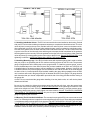
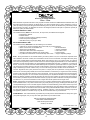
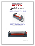
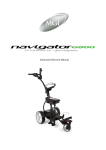
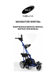
ELEKTRA® UV
E/ES-Series
Ultraviolet
Sanitizer/Clarifier
System
INSTALLATION INSTRUCTIONS
IMPORTANT SAFETY INSTRUCTIONS
SAVE THESE INSTRUCTIONS
READ AND FOLLOW ALL INSTRUCTIONS
WARNING
FOR YOUR SAFETY — This product should be installed by a
professional service technician or similar person, qualified in electrical
equipment installation. Improper installation and/or operation could cause
serious injury, property damage or death. Improper installation and/or
operation will void the limited warranty.
INSTRUCTIONS PERTAINING TO
RISK OF FIRE, ELECTRIC SHOCK
OR INJURY TO PERSON
WARNING — When using this unit, basic precautions should
always be taken, including the following:
1. READ AND FOLLOW ALL INSTRUCTIONS.
2. DANGER: To reduce the risk of injury, do not permit children to
use this unit unless they are closely supervised at all times.
3. Use this unit only for its intended use as described in this manual.
Do not use attachments not recommended by the manufacturer.
4. Never drop or insert any object into any opening.
5. This unit contains an ultraviolet bulb that can cause discomfort or
irritation to the eyes if viewing while operating. Prolonged exposure
to the eyes can cause blindness. DO NOT VIEW UV BULB WHILE
OPERATING OR DURING MAINTENANCE.
6. The unit must be connected only to a supply circuit that is protected
by a Ground Fault Circuit Interrupter (GFCI). If this unit is not
equipped (optional) with a GFCI, a GFCI should be provided by the
installer and should be tested on a routine basis. To test the GFCI,
push the test button. The GFCI should interrupt power. Push the
reset button. Power should be restored. If the GFCI fails to operate
in this manner, the GFCI is defective. If the GFCI interrupts power
to the unit without the test button being pushed, a ground current
is flowing, indicating the possibility of an electric shock. Do not
use this unit. Disconnect the unit and have the problem corrected
by a qualified service representative before using.
7. ENVIRONMENTAL NOTICE - Hg-Lamp CONTAINS MERCURY.
Manage in accord with disposal laws. See: www.lamprecycle.org
SAVE THESE INSTRUCTIONS
SAVE THESE INSTRUCTIONS
INSTALLATION INSTRUCTIONS
WARNING
When using electrical products, basic precautions should always
be followed, including the following:
1. DANGER: RISK OF ELECTRIC SHOCK. Connect only to a circuit
protected by a Ground Fault Circuit Interrupter.
2. Grounding is required. The unit should be installed and grounded by a
qualified service representative.
3. Install to permit access for servicing.
IMPORTANT: Follow the instructions EXACTLY and IN THE ORDER
LISTED. Once installed, your UV unit will provide years of successful
operation.
TABLE OF CONTENTS
0.0
1.0
2.0
3.0
4.0
5.0
6.0
7.0
Forward
Introduction
Pre-Installation
2.1 Pond Turnover Rates
2.2 Swimming Pool Turnover Rates
Desired Flow Rate Chart – Swimming Pools, Fountains, Water Features
Desired Flow Rate Chart – Ponds
Installation
5.1 Locating The UV Unit
5.2 Plumbing The UV Unit – Plumbing Diagram and Bypass Diagram
5.3 Installing Inlet/Outlet Unions
5.4 Installing Mounting Legs
5.5 Mounting The UV Unit On A Solid Base
5.6 Gluing Piping To The UV Unit
5.7 Electrical Connection
5.8 Electrical Bonding (Grounding)
5.9 Electrical Interlock Of Pump/EA Unit
Start-up
6.1 Pump Start-up
6.2 Leak Check Total System
6.3 Swimming Pool Chemical Balance
Maintenance – Quartz Tube Assembly Maintenance/Removal
7.1 Disconnect Power
7.2 Stop Circulation Pump
8.0
9.0
10.0
11.0
12.0
13.0
14.0
15.0
16.0
17.0
18.0
19.0
7.3
Remove Plastic Electrical Tee Fitting
7.4
Cleaning Quartz Tube
7.5
Re-installing Quartz Tube Assembly
UV Bulb Removal/Replacement
8.1
Electrical Connector Assembly Removal
8.2
Removing The UV Bulb
8.3
Removing the Bulb Cushion and O-Rings
8.4
Install Acorn Nut
8.5
Check For Leaks
UV Bulb Installation
9.1
Seating Bulb End Cushion
9.2
Installing O-Rings On Bulb End
9.3
Connecting Bulb Pins To Bulb Connector
9.4
Inserting Bulb Into Quartz Tube
9.5
Making Electrical Connection To Bulb
9.6
Reinstall The Electrical Enclosure Bonnet
9.7
Plug UV Unit Into Electrical Power
9.8
Providing Power To EA Unit
Maintenance – Scheduled Bulb Replacement
10.1 Annual Reminder
10.2 Disconnect The Power Cord
10.3 Remove Electrical Enclosure Bonnet
10.4 Remove The Bulb
Additional UV Unit Maintenance
Normal Operating Results
12.1 Ponds
12.2 Swimming Pools, Fountains, Water Features, Waterfalls
Winterizing
13.1 Freeze Damage
13.2 Freezing Weather Precautions
Swimming Pool Chemicals
How To Obtain Service
Parts Schematic and Part Numbers
Frequently Asked Questions
17.1 Salt Water Use
17.2 Filter Cleaning
17.3 Time Clock Operation
17.4 Residual Effect From UV
17.5 Horizontal Mounting Of UV Unit
17.6 Below Water Installation
17.7 Multiple UV Units For Larger Installations
17.8 GFCI (Ground Fault Circuit Interrupter) Necessity
Troubleshooting
18.1 UV Bulb Will Not Light At Startup
18.2 UV Bulb Was Lit, But Is Not Lit Now
18.3 UV Bulb Stays Lit When Pump Is Off
18.4 Water Is Green
18.5 GFCI Trips
18.6 Unit Makes Noise When Operating
18.7 Water Leaks From Electrical Enclosure Bonnet
Specifications
0.0 Forward: The Elektra® UV Unit is designed for use in swimming pools, fountains, water features, waterfalls
and fish ponds. It is not designed for use in potable (drinking) water installations. Use of this product in
applications other than those indicated above will void your warranty and could be harmful to your health or
the health of others.
1.0 Introduction - How The Elektra® UV Unit Works: Within the Electra® UV Unit (which we will refer to throughout
this manual as EUV), a high intensity electrically operated Ultraviolet (UV) bulb is located inside the unit’s wet chamber.
This UV bulb gives off Ultraviolet light wave emissions when lit. The bulb’s operating emission range is within the
Ultraviolet light wave spectrum at 253.7 nm of wavelength. This wavelength is such that when bacteria, protozoa,
viruses, algae spores, or other single celled waterborne microorganisms in the incoming water flow are exposed to
the light waves of the UV bulb for a proper period of time, the DNA of the microorganism is altered or disrupted and
this controls and eradicates these unwanted contaminates and renders them harmless. Your EUV unit has been sized
to produce these important UV rays in the same intensity as is required for Class A potable drinking water, which is
30 microwatts/sec/cm2.
While you may see lesser competitive units of similar vessel size claiming to work on larger ponds or pools, you will
find that these units do not operate at the same high intensity as does the EUV unit and are unable to obtain the
same level of killing power as the EUV unit. Rely on the flow chart shown herein for proper maximum killing power
unit selection for your application.
Pond or pool water containing these unwanted contaminates enters the EUV unit’s wet chamber and is exposed to
the light rays generated by the UV bulb. The EUV unit has been designed to allow for some turbidity in the water, as
turbidity will reduce the UV light wave transmission capability. Therefore, all EUV units are sized to allow for possible
turbidity in the water and the reduction in the killing power of the UV bulb when it nears the end of its useful life.
When the incoming water is exposed to the bulb for the proper duration and intensity, the water exiting the unit is near
drinking water biological quality. CAUTION!: THIS UNIT IS FOR POND OR POOL USE ONLY. DO NOT USE THIS
UNIT FOR POTABLE (DRINKING) WATER SANITIZATION.
2.0 Pre-Installation - In order to ensure that your EUV unit functions with the proper exposure time to achieve the
desired water sanitization, it is important to provide the proper water flow rate through the EUV unit. If water passes
through the unit too quickly, the exposure time of the microorganisms to the UV bulb produced rays will not be sufficient
to obtain the desired kill rate. The water flow rate through the UV unit is governed by the piping of your pool or pond
and the size and output of your circulation pump. There also needs to be consideration to the application for the UV
unit. Fish ponds have different requirements than do swimming pools, water features, fountains, or waterfalls.
2.1 Pond Turnover Rates - Most fish pond experts agree that there is no set formula for the sizing of circulation
pumps and UV systems for ponds. The size of the pond, the depth, plant coverage, the amount of sun exposure
or shade, and the number of fish in the pond all contribute to determining what the flow rate for a pond should
be. The best advise is to consult with a pond expert to determine what the flow rate for your pond should be.
This is the best method of ensuring that your pond is being circulated properly. But absent of that, a general
rule of thumb that can be used for ponds is that the water volume of the pond should be passed through the
filter system every two hours or so. Thus, if you take the volume of your pond (in gallons), and divide that by
120 (the number of minutes in two hours) you will have an approximate desired flow rate for your pond. Then,
you select a pump and filter system that works properly at that flow rate. As an example, a 6000 gallon pond
would have a desired flow rate of 50 gallons per minute (GPM) calculated at 6000 /120 = 50.
2.2 Pool Turnover Rates - Swimming pools are somewhat simpler to calculate for flow rates. Most residential
pools are designed to have the capacity of the pool turned over every 12 hours. Semi-commercial pools are
normally designed for an 8 hour turnover flow rate. Check with your local jurisdiction for the required flow rate for
your type of pool to be sure. Thus, as an example, using the same formula as above, a 20,000 gallon residential
pool will need to have a pump capable of a 28 GPM flow rate and a 25,000 gallon Semi-commercial pool will
need to have a pump capable of 52 GPM.
Like pools and ponds, the EUV unit needs to be properly sized by flow rate. Moving the water through the EUV
unit’s wet chamber too fast will not allow enough exposure time of the water to be exposed to the UV bulb rays
for the required exposure time. The following chart shows the desired and maximum flow rates for your EUV
unit. Make sure the flow rate of your circulation system pump does not exceed the maximum allowable flow rate
of the UV unit you have selected. (Consult your supplier or pump manufacturer for the pump’s GPM rating if you
are in doubt). If the pump output exceeds the maximum flow rate of the EUV unit you have selected, select an
EUV model with a higher flow rate capacity rating or consider a multiple unit installation. (See Sec. 17.7).
3.0 Desired UV Unit Flow Rates Swimming Pools, Fountains, Water Features
Delta UV
E/ES
Model
Maximum
Flow Rate
(GPM)
Maximum
Flow Rate
(LPM)
Minimum UV
Microwatts
sec/cm2
Max Volume
2 Hr. Turnover
(Gallons)
Max Volume
2 Hr. Turnover
(Liters)
Max Volume
3 Hr. Turnover
(Gallons)
Max Volume
3 Hr. Turnover
(Liters)
Max Volume
4 Hr. Turnover
(Gallons)
E/ES-5
31
140
30390
4440
16807
6660
25211
8880
33614
E/ES-10
57
295
30390
9360
35431
37440
141725
18720
70863
E/ES-20
80
416
30180
13200
49967
52800
199869
26400
99935
E/ES-40
110
469
30310
14880
56327
59520
225307
29760
112654
Note: Multiple EA units can be used for flow rates beyond those specified herein. (See Sec. 17.7)
Max Volume
4 Hr. Turnover
(Liters)
4.0 Desired UV Unit Flow Rates Ponds
Delta UV
E/ES
Model
Maximum
Flow Rate
(GPM)
Maximum
Flow Rate
(LPM)
Minimum UV
Microwatts
sec/cm2
Max Pool Volume
12 Hr. Turnover
(Gallons)
Max Pool Volume
12 Hr. Turnover
(Liters)
Max Pool Volume
8 Hr. Turnover
(Gallons)
Max Pool Volume
8 Hr. Turnover
(Liters)
E/ES-5
31
140
30390
26640
100843
17760
67229
E/ES-10
57
295
30390
56160
212588
37440
141725
E/ES-20
80
416
30180
79200
299804
52800
199869
E/ES-40
110
469
30310
89280
337961
59520
225307
Note: Multiple EUV units can be used for flow rates beyond those specified herein. (See Sec. 17.7) – Do not exceed
8 ft./sec. flow rate for your piping.
5.0 Installation — Before starting the installation, PLEASE read this manual from cover to cover. A few moments
spent initially becoming totally familiar with the EUV unit and its installation requirements will save a great deal
of time (and expense) later. If you have questions that are not answered after you have completed the reading
of this manual, contact your supplier or Delta UV. We are ready to assist you at anytime and we want your
installation to go smoothly and the equipment to work properly.
5.1 Locating The UV Unit - Once you have confirmed the sizing of your pond or pool and compared that
information against the requirements of your EUV unit by using the charts above, it is now time to install your
unit. The EUV unit comes with all internal components fully assembled and ready for installation. Only the
Inlet/Outlet unions and pressure gauge need to be installed to ready your unit for installation. All parts of the
EUV units are UV inhibited PVC plastic. Thus, your unit will function fine in the outdoors. Installing the EUV unit
indoors or inside a covered area is preferred however, to keep your unit looking new. The EUV unit will need
to be powered from a 120 V/15A electrical outlet. If the electrical outlet is outdoors and open to the weather, it
will need to be an Outdoor type receptacle. The EUV unit comes with a eight foot power cord. Do not use an
extension cord unless it is at least a 16/3 size conductor waterproof type and is no more than twenty-five feet
(7.5 meters) long.
Note: 240V / 50/60HZ units are available – Contact your dealer for more information.
5.2 Plumbing The UV Unit - Your EUV unit will need to be plumbed into your pond or swimming pool circulation
system. The diagram (Fig. 1) shows how the unit is to be plumbed. Note that the water is to be piped from the
pressure side of the pump and after the filter, in and out of the EUV unit. The inlet for the water is at the bottom
of the EUV unit, and the outlet is at the top of the EUV unit. If your pump exceeds the maximum flow rate of
the EUV unit, installation of a plumbing by-pass will be necessary to bypass some of the pump’s flow around
the EUV unit so the maximum flow rate of the EUV unit will not be exceeded. A typical bypass arrangement is
shown in Fig. 2
5.3 Installing Inlet/Outlet Unions - The EUV unit comes with union nuts installed on the housing. Packed
with your EUV unit are the remaining components necessary to complete the Inlet/Outlet unions. The clear
union tail piece is used on the top union, and the solid color union tail piece is used on the bottom union.
Also packed with your EUV unit are two white gaskets that are used to complete the Inlet/Outlet unions.
One side of the gasket is flat, the other side has a half round bead on the face. The two unions each have
a groove in the face of the union tail piece and that groove accepts the half round bead of the gasket to
hold the gasket in place correctly. Place the gaskets into the face of the union tail pieces. Now, install the
union tail pieces by screwing them into the union nuts on the EUV unit. DO NOT OVERTIGHTEN. Hand
tightening is sufficient. OVERTIGHTENING WILL BREAK THE UNION NUTS.
5.4 Installing Mounting Legs - Your EUV unit also comes with a pressure gauge that is used to confirm
that your pump is not exceeding the 40 PSI maximum working pressure for the EUV unit. The pressure
gauge is shipped with Teflon sealing tape on the gauge threads. To install the pressure gauge, screw it
into the threaded tap on the clear union tail piece that you have installed on the EUV unit. If the EUV unit
is installed indoors, the pressure gauge can be installed so it is facing upward. However, if the EUV unit
is installed outdoors, the pressure gauge must be installed on one side or the other of the clear tailpiece
so that it will be in a vertical position when installed. Installing the gauge facing upwardly when the EUV
unit is outdoors will result in the gauge filling full of rainwater and will ruin the gauge. The gauge location
and orientation that you choose is dependent upon which side of the fitting provides the best viewing of
the gauge dial.
Caution: Do not cross-thread the gauge when installing it into the plastic union, as it will ruin the plastic
threads and will leak.
Be sure to use a wrench to tighten the pressure gauge into the clear tail piece, using the square brass
boss on the back of the pressure gauge. DO NOT OVERTIGHTEN. Over tightening will cause the clear
plastic union tail piece to crack. Three or four threads are all that is necessary to seal the pressure gauge.
If the gauge leaks upon start-up, simply tighten one more rotation. DO NOT TIGHTEN BY GRASPING
THE COVER OF THE PRESSURE GAUGE. Only use the square brass boss on the back of the pressure
gauge for tightening with a wrench.
5.5 Mounting The UV Unit On A Solid Base - The next step is to secure the EUV unit to a concrete or wood
base. Four mounting holes are located in the mounting base of the EUV unit. These holes accommodate
¼ inch diameter bolts to mount the EUV unit in place. FAILURE TO PROPERLY SECURE THE UNIT MAY
CAUSE NOISE DUE TO VIBRATION CAUSED BY WATER PASSING THROUGH THE WET CHAMBER.
Secure the EUV unit using bolts and anchors (not supplied) where necessary and appropriate for your
installation. When the EUV unit is secured in position, the piping of the unit can begin.
5.6 Gluing Piping To The UV Unit - The Inlet/Outlet PVC union tail pieces are 2 inch pipe size (63mm for
overseas models). Your PVC supply piping should be glued into the union tail pieces using an appropriate
PVC primer and PVC cement, as recommended by your supplier. Inlet piping should be supported and
should not rest solely upon the unions, to avoid breaking the unions. The installation of valves on the inlet
and outlet lines attached to the UV unit is recommended. If the EUV unit is located with any portion of
the unit below the surface of the pond or pool, then VALVES ARE MANDATORY, so you may winterize or
remove the EUV unit without draining your pool or pond. When you have completed the piping installation
(including bypass if necessary), the final step is to plug in the unit to its power source.
5.7 Electrical Connection - The electrical power rating for your EUV unit is shown on the label on the
outside of the unit. US and Canadian EUV units operate on 120V/50/60 Hz – (1.15 Amps maximum).
This low power consumption makes operating your EUV unit very economical. Therefore, you will need a
15Amp 120V receptacle for your EUV unit to plug into. (Check the label on your overseas unit for its power
requirement). Your EUV unit is supplied with an eight foot long weatherproof power cord terminating in either
a 3-prong grounded NEMA plug, or in an optional cord connected Ground Fault Circuit Interrupter (GFCI).
Whether you use the factory installed GFCI or install a GFCI in the electrical outlet or in the breaker panel
serving the EUV unit power receptacle, you will need to have the unit GFCI protected. Note: Should the
electrical power cord of your EUV unit become frayed or damaged in the future, unplug it from the power
receptacle and replace it immediately.
If you did not order your EUV unit with the cord connected GFCI installed, you may add it in the field. You
will need to order Part # 70-09012 (Retrofit Cord Connected GFCI Kit) from the supplier of your EUV unit.
This kit comes complete with everything you need to install the weatherproof GFCI on the end of the EUV
unit power cord. Easy to follow installation instructions are included with the kit and should take only a
few minutes to complete. Verify that you have power to your electrical outlet and then plug the EUV unit
power cord into your power outlet.
5.8 Intentionally Left Blank
5.9 Electrical Interlock Of Pump/EA Unit - The EUV unit is equipped with a safety pressure switch that does
not allow the UV bulb inside the unit to light unless there is at least 5 PSI operating pressure inside the chamber.
This is to ensure that the bulb will not create heat when the EUV unit is empty or water is not flowing in the wet
chamber. Such excessive heat can shorten the life of the UV bulb. Therefore, only when the pump is pumping
water through the EUV unit wet chamber will you be able to see the UV bulb glow and confirm that it is on.
Note: Low pressure 1/2 psi pressure switches are available if you have a low pressure piping system (found
most frequently in Koi pump installations). Order P/N 70-02315. Without the circulation pump operating, you will
not see the bulb light up just by plugging the EUV unit into its electrical outlet. Once the pump is pumping water
thought the EUV unit, as confirmed by the indication of pressure on the pressure gauge, the bulb will light. To
confirm that the bulb is indeed lit, you can view the glow of the bulb through the clear plastic union tail piece at
the top outlet of the EUV unit. This is the only location where you should attempt to view the UV bulb while it is
on. The PVC union tail piece screens out the harmful UV rays and can be viewed with the naked eye without
any damage to the eyes. If the bulb is not lit, check the troubleshooting section at the end of this manual.
6.0 Start-Up - Once you have completed all the preceeding steps, (IMPORTANT) verification that the unit has
no leaks anywhere, including a possible broken quartz tube damaged during transit, you are ready to start your
unit up.
6.1 Start Up Circulation Pump - Once the pump is on, be sure to drain all air from your system through
the air relief valve on the filter, if so equipped.
6.2 Check EUV Unit For Leaks - Make one final check for leaks in your piping, accessories, and under
the electrical enclosure bonnet. If any water leakage under the EUV unit’s electrical enclosure bonnet is
suspected (water dripping from under side of bonnet), disconnect the EUV unit immediately, remove the
bonnet (see 7.3) and verify that there is either (a) no leakage or (b) stop the leakage of the quartz tube
gasket. If quartz tube leakage is encountered, follow the instructions in Sections 7.4 through 7.6 and 8.1
through 8.5 to remedy the situation before applying electrical power to your EUV unit.
6.3 Swimming Pool Chemical Balance - Check the chemical balance of your swimming pool and
adjust the chemical balance as per your pool chemical suppliers instructions. - Remember, the EUV unit
dramatically reduces the need for chemical sanitizers, but does not eliminate the need for proper pool
chemical balance.
7.0 Quartz Tube Maintenance - The EUV unit requires very little maintenance during the year. The UV bulb
in the EUV unit is placed inside a quartz tube to protect the bulb from the water in the EUV unit’s wet chamber.
This quartz tube can have its ability to transmit the UV rays from the bulb through the quartz tube diminished if
the quartz tube becomes dirty or laden with deposits. The quartz tube should be removed from the wet chamber
every six (6) months and inspected to make sure it is clean and that deposits are not attached to the quartz tube.
To remove the quartz tube, you should follow the steps shown below.
7.1 Disconnect Power - Unplug the EUV unit from its power receptacle.
7.2 Stop Your Circulation Pump - You must shut off the circulation pump so that no water is flowing
into the EUV unit. Once the pump is shut off, verify on the pressure gauge that the pressure inside the
EUV unit is ZERO. If any pressure is indicated on the pressure gauge, do not go to the next step until the
pressure gauge shows ZERO. If you show any pressure on the pressure gauge, but feel that there is no
pressure present inside the EUV unit, simply unscrew the top union nut on the EUV unit. This will relieve
any pressure. With the union partially unscrewed, the pressure gauge should show ZERO. If it does not,
replace the pressure gauge (Part # 84-82234) immediately. When you are absolutely sure that there
remains no pressure inside the EUV wet chamber, you can proceed to the next step.
7.3 Remove The Plastic Electrical Enclosure Bonnet – NEVER REMOVE THE ELECTRICAL
ENCLOSURE BONNET WITHOUT FIRST UNPLUGGING THE EUV UNIT FROM ITS POWER SOURCE
– DO NOT OPERATE THE EUV UNIT WITH THE BONNET REMOVED - The electrical enclosure bonnet
is removed by unscrewing the four mounting screws that hold the bonnet to the EUV unit.
7.4 Remove The UV Bulb - Do not handle a hot UV bulb. First make sure the bulb is cool before handling
to avoid burning your skin. Unplug the UV bulb by grasping the white bulb connector attached to the ballast
wires. Slowly pull the UV bulb out of the quartz tube by grasping the bulb on the white ceramic prong end.
DO NOT TOUCH THE UV BULB GLASS WITH YOUR BARE HANDS! Use a soft clean cotton cloth or
clean cotton gloves to handle the UV bulb. Skin oils on your hands can attach to the bulb and can cause hot
spots on the bulb which can shorten the bulb life. Carefully place the removed bulb in a safe location while
cleaning the quartz tube. The quartz tube is now ready to be removed from the EUV unit for cleaning.
7.5 Remove The Acorn Nut - Using a crescent wrench or 1-11/16" socket, remove the black plastic
acorn nut (Part # 86-02411) holding the quartz tube into the black plastic mounting gland. Note that there
is a rubber sealing gasket (Part # 44-02018) around the quartz tube (or inside the acorn nut) that seals
the quartz tube to the mounting gland. Set the gasket aside to reseal the quartz tube when you reinstall
the quartz tube after cleaning.
7.6 Remove The Quartz Tube - First make sure the quartz tube is cool. Do not handle a quartz tube until
it cools. Grasp the quartz tube that is extended above the mounting gland and pull straight up to remove
it from the EUV unit wet chamber. The quartz tube can now be easily cleaned.
7.7 Cleaning The Quartz Tube - The quartz tube exterior can normally be cleaned by mixing a mild
solution of Muriatic Acid (available at all pool supply stores) with water in a ratio of four parts water to
one part acid. CAUTION: Follow the directions for use and handling of Muriatic Acid on the acid bottle
label, being careful to protect your eyes, wear rubber gloves, and avoid breathing fumes. DO NOT USE
ABRASIVE CLEANERS as they can scratch the high quality quartz glass. If lime or hard water calcium
deposits are encountered, lime removal products that are available in grocery stores can be used. These
products will not harm the hard glass surface of the quartz tube. Complete the cleaning of the quartz tube,
wash it off and wipe it dry. Also, make sure the inside of the tube is dry before placing the UV bulb back
inside the quartz tube.
Lastly, carefully inspect the cleaned quartz tube for cracks. If any cracks in the quartz tube are found,
the tube should be replaced. Broken quartz tubes will allow water to enter the dry electrical chamber
and attack the electrical components of the unit, which will cause them to fail and need to be replaced.
BROKEN QUARTZ TUBES, OR WATER DAMAGE CAUSED BY BROKEN QUARTZ TUBES, ARE NOT
COVERED UNDER YOUR LIMITED WARRANTY.
8.0 Reinstalling The Quartz Tube – The process of reinstalling the quartz tube is just the reverse of the removal
process.
8.1 Electrical Connector Assembly Removal - Insert the quartz tube into the wet chamber by carefully
inserting it into the threaded quartz tube sealing gland.
8.2 Removing The UV Bulb - Seat the quartz tube into the receptor at the bottom of the wet chamber.
The quartz tube will not go all the way down into the wet chamber unless the rounded end of the quartz
tube is seated in the receptor at the bottom of the wet chamber.
8.3 Removing the Bulb Cushion and O-Rings - Place the black rubber sealing gasket all the way down
into the black plastic acorn nut, with the angled edge of the gasket facing downwardly when the nut is
installed on the sealing gland. DO NOT place the gasket on the quartz tube and then try to push the acorn
nut over the gasket. This will not allow the gasket to seal properly.
8.4 Install Acorn Nut - Screw the acorn nut onto the threads of the sealing gland, being careful not
to cross thread the plastic nut. Tighten the acorn nut with a wrench, socket or crescent wrench. DO
NOT OVERTIGHTEN. This will crack the acorn nut and the rubber gasket will not seal the quartz tube
properly.
8.5 Check For Leaks - Turn the circulation pump on and check the quartz tube seal for leaks. Correct
any leak found by carefully tightening the acorn nut ¼ turn. If the leak persists, remove the acorn nut and
bulb sealing gasket, inspect the bulb sealing gasket and replace if necessary. Follow previous procedures
for installing the acorn nut and seal and recheck the EUV unit for leaks again. Turn the circulation pump
off once you have confirmed that the quartz tube is not leaking.
9.0 Reinstalling The UV Bulb – DO NOT TOUCH THE UV BULB GLASS WITH YOUR BARE HANDS. Oils
on your hands transfer to the bulb glass and cause hot spots on the bulb surface. If you have touched the bulb
with your bare hands, you must wipe the bulb glass off with Denatured Alcohol using a clean soft cotton cloth
before inserting the bulb back into the quartz tube.
9.1 Seating Bulb End Cushion - Seat the bulb end cushion on the end of the bulb (the end that goes
down into the quartz tube first).
9.2 Installing O-Rings On Bulb End - Place the two O’Rings around the top white porcelain bulb end
cap (where the electrical pins are located).
10
9.3 Connecting Bulb Pins To Bulb Connector - Slowly lower the bulb down into the quartz tube until
the bulb O’Rings are down inside the quartz tube. Make sure the bulb O’Rings have not become dislodged
from the white ceramic on the end of the bulb while the bulb is being inserted down into the quartz tube.
Reposition the bulb O’Rings if necessary.
9.4 Inserting Bulb Into Quartz Tube - CAUTION: DO NOT INSTALL THE ELECTRICAL SOCKET FROM
THE BALLAST TO THE FOUR PINS ON THE END OF THE BULB AT THIS TIME. DOING SO NOW
WILL CAUSE THE BULB TO LIGHT WHEN THE PUMP IS TURNED ON AND EXTENDED VIEWING
OF THE LIGHT BULB CAN CAUSE BLINDNESS OR EYE INJURY. DO NOT LOOK DIRECTLY AT THE
LIT BULB AT ANY TIME.
9.5 Making Electrical Connection To Bulb - Once you have verified that the quartz tube seal is not
leaking, TURN OFF YOUR PUMP IF YOU HAVE NOT DONE SO PREVIOUSLY. Then, WITH THE PUMP
OFF, connect the electrical socket from the ballast to the four pins on the bulb by pushing the socket down
over the pins. NOTE: The socket will only install on the bulb pins in two opposite orientations. The pins
are not equally spaced in all directions, so check the pin alignment before pushing down on the electrical
socket. Once you are sure that the socket openings mate up to the pins, you can push the socket down
onto the pins. DO NOT force the socket onto the pins. If force is needed, it means you have not aligned
the pins to the socket.
9.6 Reinstall The Electrical Enclosure Bonnet - Place the plastic electrical bonnet on the top of the
EUV unit on the four brackets provided, and tighten the screws using a Phillips screwdriver. DO NOT over
tighten the screws.
9.7 Plug The EUV Unit Power Cord Into The Power Receptacle - The bulb will not light until the pump
is turned back on due to the pressure switch remaining open until pump pressure inside the wet chamber
is sensed, verifying the water flow through the EUV wet chamber.
9.8 Providing Power To EA Unit - Turn the circulation pump on and verify that the bulb is lit by viewing
the glow of the bulb through the clear plastic union fitting at the outlet of your EUV unit. Your EUV unit is
now ready for service.
10.0 Scheduled UV Bulb Replacement - In addition to cleaning of the quartz tube periodically, annual
replacement of the UV bulb is required. The High Output UV bulb in your EUV unit has a useful life of approximately
9000 hours of operation, which is about one year of continual use. 9000 HOUR BULB REPLACEMENT IS
MANDATORY – Even though the bulb may be glowing after 9000 hours of operation, do not operate your EUV
unit longer without replacing the bulb as the bulb will have reached its useful ability to do its job by then. Bulb
replacement is best done at the same time as quartz tube cleaning to minimize your maintenance efforts. This
can be accomplished with a little planning ahead. You should schedule one of your quartz tube cleanings to take
place at the required 9000 hour bulb replacement time occurrence.
As a point of information, it should be noted that if you start and stop your circulation pump frequently, such as
by daily time clock operation, you will cause the bulb to be more susceptible to burning out more quickly than if
used continually. This is the same phenomenon you see when you turn on a table lamp and it flashes and burns
out. The momentary inrush of billions of electrons that occurs when a bulb is first energized has a detrimental
effect on the filament of all bulbs, thus the cause for a potentially shorter bulb life.
10.1 Annual Reminder - It is recommended that you mark your calendar for bulb replacement ten or
eleven months from the initial date of installation of your Elektra UV unit. This will give you ample time to
obtain a new bulb from your supplier before re-lamping is required. If your application is critical, as in a
Koi pond, where you absolutely do not want to have your EUV unit out of service for any period of time,
it is suggested that a spare bulb be kept on site so you can change out the bulb immediately in the future
if replacement is needed. Bulb replacement is accomplished as follows:
10.2 Disconnect The Power Cord - First, disconnect your EUV unit from its power source by unplugging
the power cord from the electrical receptacle. This is a MUST anytime you remove the electrical enclosure
bonnet for any reason.
11
10.3 Remove Electrical Enclosure Bonnet - Follow Sec. 7.3 instructions to remove the electrical
enclosure bonnet.
10.4 Remove The Bulb - Follow the steps noted for bulb removal and replacement during quartz tube
removal (Sec. 7.0) and installation (Sec 9.0) to remove the old bulb and complete the installation of a
new bulb.
11.0 Additional Maintenance - While not required for the function of your EUV unit, you can keep your EUV
unit looking new by periodically applying a light coat of car wax to the exterior of the unit at initial installation,
then periodically thereafter as required. This is especially important to protect the look of the ES Series mirror
polished stainless steel exterior. Be careful not to damage the silver product identification label, as EUV units
returned for service with missing or mutilated labels will not be warranted. No other scheduled maintenance
of your EUV unit is necessary. All other components not mentioned previously do not require any preventive
maintenance. Should any component be needed, you can identify the component part number in Sec.16 of this
manual and obtain it from your original supplier, or if he does not have it, then from Delta UV directly.
12.0 Normal Operating Results – Ponds, swimming pools, fountains, waterfalls and water features have
different disinfection and clarification needs than fishponds. The EUV unit provides those needs in the same
manner equally effectively, for all types of water environments specified herein.
12.1 Normal Operating Results (Ponds) - On properly sized and installed pond installations, you can
expect to correct green water condition in 3-5 days of continuous operation after start-up. Remember,
only water that enters the EUV wet chamber is exposed to the UV rays of the bulb, so algae that clings
to the sides and bottom of your pond will not be affected by installing an EUV unit. This is normal and the
retention of biologicals outside the EUV unit is desired for proper bio-filtration. Thus, the EUV unit will not
harm your bio-filtration, fish population or pond ecosystem.
12.2 Normal Operating Results (Swimming Pools, Fountains, Water Features) - You will see a
significant improvement to your water clarity and the “chlorine odor” should disappear in 2-4 days of continual
operation after start-up on properly sized and installed pools, fountains, waterfalls and water features.
Remember, as noted before, the EUV unit will dramatically reduce the pools reliance on sanitizers and algae
control products. Many users of UV units report a 70%-85% reduction in their chemical use. This is not
only desired due to reduced operating costs, but the major reduction of sanitizer levels makes for a more
healthier bathing environment. REMEMBER, you must continue to check your water chemistry regularly
as required for your water vessel, and some sanitizing chemicals will still be necessary to supplement the
sanitization and control capability of the EUV unit.
13.0 Winterizing – Your EUV unit can be damaged if allowed to freeze. The substantial pressure inside the
wet chamber caused by ice forming inside the wet chamber can break the glass quartz tube as well as the wet
chamber itself. Therefore, you must protect your EUV unit from freezing. Damage due to freezing, including
breakage of glass components, the wet chamber, or water damage to other components caused by freezing IS
NOT COVERED under your Limited Warranty.
13.1 Freeze damage - Freeze damage can be avoided by keeping the water flowing at a minimum of 5 PSI
pressure (as noted on the pressure gauge) at all times, without interruption during freezing temperatures.
All time clocks must be inoperable and the pump must run continuously. Freeze damage can also be
avoided if the pump and EUV unit are maintained inside a warm enclosure.
13.2 Freezing Weather Precautions - If you do not plan to operate your EUV unit during freezing
temperatures, you must take precautions to make sure all water is removed from inside the EUV wet
chamber so it does not freeze inside the wet chamber and damage the EUV unit. This can be accomplished
by first closing any valves on lines in the plumbing system and then open the inlet union at the bottom of
the EUV unit so that the water is drained from inside the wet chamber tank. A safe precaution is to place
the EUV unit in a warm location during freezing temperatures, after draining all the water from the unit
and removing it from the plumbing. Caution: A drain valve and piping to carry water away from the EUV
unit must be installed if drainage of the EUV unit will cause water damage to the area surrounding the
EUV installation.
12
14.0 Swimming Pool Chemicals – Your EUV unit does not add any chemicals to your swimming pool or pond
water. Its job is to kill bacteria, parasites, microorganisms and algae that come into contact with the UV rays
inside the EUV unit’s wet tank. It is important to maintain a chemical regiment as directed by your pool chemical
supplier, however you will notice a dramatic decrease in chemical usage as one of the side benefits of the EUV
unit is that it attacks the chloramines that form in pool water when sanitizing chemicals are inadequate or when
bathing loads are heavy.
15.0 How To Obtain Service – In the unlikelihood that service is required, contact your supplier and the supplier
can advise the best method of providing the services you need. In some instances, the supplier will handle the
required service themselves, including the ability to supply any necessary parts. In other instances, the supplier
will refer you to Delta UV, who can assist you as well. Please read the Limited Warranty in this manual for your EUV
unit. It explains fully what is and what is not covered under the Limited Warranty and the warranty periods.
16.0 Parts Schematic – The following diagram shows all replaceable components of your EUV unit.
E SERIES & ES SERIES
17.0 Frequently Asked Questions – Here are a number of FAQ’s that will answer some of the most common
questions.
17.1 Is the Elektra® UV System Designed For Salt Water Use? – While the ability of the system is not
affected by salt water, the harsh environment found in salt water ponds and aquariums is not recommended
for the ES Series units due to the stainless steel inner wrapper. However, the all plastic E-Series units are
compatible with salt water environments.
13
17.2 Do I Need To Turn My EUV Unit Off When I Clean My Filter? - No, the flow sensing pressure
switch that is part of your EUV unit will automatically shut the UV bulb off until proper water flow inside
the EUV unit is re-established. Should you need to turn your unit off for any reason, this is accomplished
by simply unplugging the EUV unit from its power outlet.
17.3 Will A Time Clock On My Pool Shorten My Bulb Life? - Some shortening of the bulb life can be
expected when the EUV unit is turned off and back on frequently. A daily on/off cycle will not create a major
bulb life issue however, frequent on/off cycles should be avoided.
17.4 Is There Any Residual Effect From UV? - No, UV light is used as a control and is applied only to
the water that passes inside the EUV wet chamber in visual contact with the UV transmission from the
UV bulb.
17.5 Can The EUV Unit Be Mounted Horizontally? - No, vertical mounting is required to maintain the
weatherproof integrity of the electrical enclosure bonnet.
17.6 Can The EUV Unit Be Installed Below The Pond or Pool Waterline? - The EUV unit has a
pressure switch that controls the on/off cycle of the UV bulb when the pump stops or starts. If the EUV unit
is installed (example, in a vault below the waterline of the pond or pool), a static head of water pressure
may be sufficient to cause the pressure switch to remain closed, which means that the UV bulb will remain
lit at all times while the EUV unit is plugged into its power source. Contact Delta UV or your supplier for
a different type of pressure switch (Part # 70-02301) that can be adjusted to allow for this static water
pressure in the EUV wet chamber. Installation of this type of pressure switch takes only a few minutes
and will restore the desired ability of the bulb to be turned off automatically when pumping is interrupted.
DO NOT OPERATE YOUR UNIT WITHOUT A PROPERLY WORKING PRESSURE SWITCH. To check
your switch to see if it functions properly, follow the instructions given in Sec. 18.
17.7 Can Multiple Units Be Used Together For Larger Systems? - Yes, you can add any number
of EUV units to a plumbing bypass manifold system to allow for larger outputs and flow rates beyond
the capacity of a single E-40 or ES-40 unit. Delta UV also manufactures a large capacity system, the
Elektra® Max UV system, that incorporates factory installed hydraulically balanced piping and multiple
tanks contained within a metal enclosure. The Elektra Max system features the latest technology in high
output UV bulbs, dubbed Amalgam bulbs. Contact Delta UV or your supplier for information on the Elektra
Max product line, or to obtain a drawing showing the proper method of plumbing multiple EUV units for
larger applications.
17.8 Must I Use A GFCI (Ground Fault Circuit Interrupter) With My UV Unit? - Yes. A 15 Amp 120V
GFCI can be factory installed in your EUV unit at time of manufacture (optional), or you can install it in
the electrical receptacle that is used to power your EUV unit. Additionally you can install it in the electrical
panel (GFCI breaker) that services the electrical circuit of your EUV unit, or if you want to install the field
retrofit weatherproof cord connected GFCI, it is easily installed on the end of the EUV unit’s electrical
power cord. Installation is simple and takes only a few minutes by following the simple directions supplied.
No special tools are required. You can order the cord connected GFCI kit (Part # 70-09012) from your
supplier or from Delta UV.
18.0 Troubleshooting – The list below will help guide you through any problems you may have at time of initial
installation or in the future. For additional assistance, contact your supplier or Delta UV at the address, e-mail,
fax or phone shown at the end of this manual.
18.1 The UV Bulb Will Not Light - If this occurs upon initial start-up, the problem could be caused by a
number of issues.
a. The pressure switch is open. This is caused by low pressure in your system. Make sure the pump is
on (the bulb will only light when there is 5 psi water pressure inside your EUV unit’s wet chamber).
Verify that the pressure gauge reads 5 PSI or more. If it does not read at least 5 psi, reduce flow
exiting the EUV unit by partially closing the valve on the discharge piping exiting the EUV unit. This
will increase the pressure inside the EUV wet chamber. - A low pressure 1/2 psi pressure switch
(P/N 70-02315) is also available and can be installed in lieu of the 5 psi pressure switch supplied.
14
b. The bulb has become disconnected from the bulb connector. Disconnect the power cord from
the electrical outlet, open the electrical enclosure bonnet and confirm the bulb connector is
firmly in place. At the same time, check all exposed wires for a possible loose connection. Plug
the electrical cord back into the electrical outlet ONLY after the electrical enclosure bonnet has
been re-installed on the EUV unit.
c. Verify that the electrical cord is plugged into a hot outlet. Test the electrical outlet. You should
confirm the availability of the same power as indicted on the electrical label on your EUV unit.
d. Make sure you have not plugged your unit into any power source other than that specified on
your unit’s electrical label. If you have done so in error, the ballast has been damaged and needs
to be replaced. Contact your supplier for the correct replacement ballast. (Not warranted)
18.2 The UV Bulb Is No Longer Lit - This occurs after the unit has been operating successfully for a
period of time.
a. The bulb has burned out. Replace the UV bulb.
b. The ballast has burned out. Contact your supplier or Delta UV for assistance in obtaining a new
ballast.
c. Verify that the electrical outlet where the EUV unit is plugged into has the proper voltage and
the cord is securely plugged into the outlet.
d. Verify that the GFCI has not tripped. To verify the operating state of the GFCI, trip the GFCI
manually and reset it manually. The GFCI should reset. If it does not, it indicates a fault to ground
in the electrical circuit or the EUV unit itself.
18.3 The UV Bulb Stays Lit When The Pump Is Off - The EUV unit is equipped with a safety pressure
switch that turns the UV bulb off when the pump is turned off. This function guards against having the bulb
lit accidentally when the electrical enclosure bonnet is removed and serves to ensure that there is water
flowing in the EUV unit wet chamber to cool the bulb and extend its life.
a. If the EUV unit is located below the water level of the pond or pool, there is a static head of water
that causes pressure to be found inside the wet chamber. This static head of pressure closes
the pressure switch and the bulb stays lit even when the pump is off. Contact your supplier or
Delta UV to obtain a special pressure switch that can be adjusted to allow for the static head of
water.
b. If the EUV unit is located above the water level of the pond and the bulb stays lit when the pump
is off, replace the pressure switch.
18.4 The Water Is Green - Green water is an indication that the UV rays generated by the EUV unit are
not effective or are not being generated by the UV bulb.
a. Check the bulb to make sure it is on. If it is not on, follow the procedures above regarding the
UV bulb not lighting.
b. Run your unit longer. If your unit is operating on a time clock, run the circulation pump longer
to allow the EUV unit to function fully.
c. Clean the quartz tube.
d. Replace the UV bulb if it is nearing the 9000 hour useful life. At 9000 hours of operation, the
UV bulb is 80% as effective as it was when it was new. This is normal for all low-pressure type
UV bulbs, which are the longest life bulbs used in this type of application.
15
e. If your EUV unit is installed on a swimming pool, shock the pool with the sanitizing chemical you
normally use and balance the pool water as per your chemical manufacturers specifications.
18.5 The GFCI Has Tripped - The GFCI protects the system from any fault to ground, as the electrical
breaker protects the electrical circuit. When it trips, it is an indication that there is an electrical problem
that must be corrected to provide a safe operating environment in your pool or pond.
a. GFCI Not On End Of Power Cord - Disconnect the EUV unit from the electrical receptacle.
Reset the GFCI at the breaker panel or at the receptacle. If the GFCI does not reset, replace
the GFCI. If the GFCI does reset, plug the EUV unit into the electrical receptacle and make
sure the pump is on. If the GFCI trips, it is an indication that there is a ground fault inside the
EUV unit. Follow instructions previously given for opening the electrical enclosure bonnet and
inspecting the EUV unit.
b. GFCI Is On End Of Power Cord – Try to reset the GFCI – If the GFCI won’t reset, inspect the
power cord for fraying or damage and if none is found, unplug the power cord from the electrical
receptacle.
c. If water is present inside the electrical enclosure bonnet, it will trip the GFCI. Following instructions
given previously, remove the quartz tube, inspect it for cracks or breakage or for a bad quartz
tube seal. Re-seal the quartz tube.
d. Regardless of where your GFCI is located, you can check the UV bulb for GFCI trip cause by
unplugging the bulb from the bulb connector, then place the electrical enclosure bonnet back
on the EUV unit and power up the circulation pump. Reset the GFCI and if it does not trip, it
indicates that the UV bulb is causing the fault to ground. Replace the UV bulb. If the GFCI does
not reset, then the problem is with the Ballast. Replace the ballast.
18.6 The EUV Unit Makes Noise When Operating - This is an indication of the EUV unit not being
properly attached to a firm mounting base of wood or concrete with the bolts placed through the mounting
holes in the EUV unit base. It can also indicate that the UV bulb was installed without the required bulb
cushion and/or bulb O’Rings. Attach the EUV unit correctly to a firm base as described in Sec. 5.5, or
install the bulb cushion and/or bulb O’Rings as described in Sec. 9.0.
18.7 Water Is Coming Out Of Electrical Enclosure - Water exiting the unit through the electrical enclosure
bonnet can be attributed to either (a) a bad quartz tube seal, or (b) a broken or cracked quartz tube. Check
the quartz tube seal and quartz tube as instructed in Sec. 7.0 and Sec. 8.0.
19.0 Specificatons - Due to Delta UV’s commitment to product improvement, all product descriptions or
specifications are subject to change without notice.
16
ELEKTRA® UV LIMITED WARRANTY
3 Year - 2 Year
Delta Ultraviolet Corporation warrants to every original Purchaser of Delta UV’s Elektra® Series Ultraviolet Unit, that
the product will be free from defects, as defined herein, for a period of either three (3) years - (ES-Series) or two (2)
years - (E-Series). If at any time during the Limited Warranty period, any defect, as defined herein, prevents the product
from performing correctly in an application for which it was designed, Delta UV will repair or replace the product (at
Delta UV’s option) as outlined herein:
COVERED WARRANTY ITEMS:
This Limited Warranty DOES cover the UV unit, its components, and defects thereof against:
• Manufacturing Defects
• Material Defects
• Housing Corrosion Causing Leakage (ES Series)
• Plastic Component Degradation
• Bulb failure during 1st year, (Pro Rata)
NON-COVERED WARRANTY ITEMS:
This Limited Warranty DOES NOT cover the following UV unit defects:
• Failure Of Any Covered Condition When Caused By Any Of The Following:
• Metal Corrosion Due To Salt Water Use • Mechanical Abuse
• Glass Component Breakage
• Improper Installation
• Bulb Failure After 9000 Hours Of Operation • Acts of War or God
• Operation At Pressures Greater Than 40 PSI (3 Bar) • Freeze Damage
• Any Failure Not Indicated As “Covered Warranty Item” Herein • Improper Operating Voltage
Note 1: During the duration of this Limited Warranty, should any failure occur, the unit should be inspected at the
site to determine the cause of failure, and if that failure is shown to be a covered item, the Original End User (User)
must request a written Return Goods Authorization (RGA) from Delta UV, prior to any product return. Any returned
unit is to be accompanied by Delta UV’s RGA and is to be returned freight prepaid to Delta UV for Limited Warranty
evaluation. The User is responsible for any freight damage associated with such return. Unit failures, or components
thereof, found to be covered under this Limited Warranty will be repaired or replaced (at Delta UV’s option) without
cost to the User and will be returned to the User via UPS Surface, at the User’s expense. Delta UV shall be the sole
judge in determining the cause of failure of any UV unit. Units arriving in broken condition will not be warranted.
The term “Original End User” (User) shall mean the person or company that was in possession of the physical location
where the UV unit was originally installed, at the time of first installation, as evidenced by an original invoice from the selling
company to the User at the location where the unit is to be returned. A photo copy of said original invoice must accompany
the UV unit RGA paperwork. UV units received unaccompanied by the required documentation will not be accepted by
Delta UV for Warranty evaluation and will be returned to the User in the same condition as received, freight collect (COD) if
the User fails to provide the required documentation within ten (10) days from date of notification of missing documentation
from Delta UV. Any unit returned to Delta UV COD or freight collect will be rejected from the freight carrier.
Note 2: This Warranty is Limited in that it does not cover any monetary reimbursement for freight charges, for removal
and/or installation labor, or any other incurred costs by any other person(s) or firm(s), including (but not limited to) any
consequential damage or loss of use that might be claimed. The Limited Warranty period shall commence upon the
date of sale to the User, but in all cases no later than one hundred twenty (120) days after the date of manufacture of
the UV unit, as shown on the Delta UV date code located on the product identification label, whichever occurs first.
UV units received with factory identification missing, mutilated or altered, or units received containing components
not supplied by Delta UV or modified in any way, will not be warranted under any circumstances.
OTHER RIGHTS - This Limited Warranty supersedes any and all previous Limited Warranties for this product, gives
you specific legal rights, and you may have other rights which vary from state to state.
DELTA ULTRAVIOLET CORPORATION
CORPORATE HEADQUARTERS
14936 South Figueroa Street
Gardena, CA 90248
P/N 94-06231 REV. 1/06
17
REFERENCE INFORMATION
DEALER _____________________________________________
_____________________________________________________
_____________________________________________________
_____________________________________________________
PHONE ______________________________________________
CONTACT ____________________________________________
DATE OF INSTALLATION _________________________________ MODEL _________________
RE-LAMP DATE _________________________ RE-LAMP DATE __________________________
RE-LAMP DATE _________________________ RE-LAMP DATE __________________________
RE-LAMP DATE _________________________ RE-LAMP DATE __________________________
RE-LAMP DATE _________________________ RE-LAMP DATE __________________________
- NOTES -
18
- NOTES -
19
14936 South Figueroa Street
Gardena, CA 90248
310-577-1840 PHONE
310-305-9755 FAX
[email protected]
IMPORTANT SAFETY INSTRUCTIONS
SAVE THESE INSTRUCTIONS
P/N 94-35237 Rev. 5/08
©2008 Delta Ultraviolet Corporation