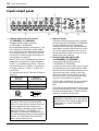
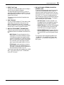
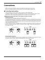
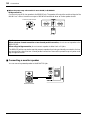
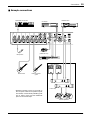
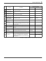
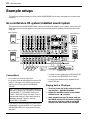
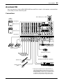
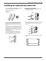
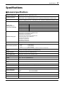
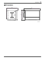
1
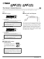
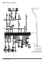
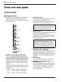
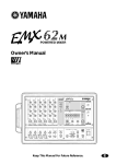
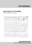
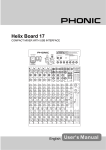
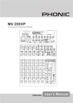
Owner’s Manual
Keep This Manual For Future Reference.
E
The Owner’s Manual Revisions
E
Thank you for purchasing the Yamaha EMX88S/EMX68S Powered Mixer. Parts of the EMX88S, EMX68S owner’s manual have been
revised. Please refer to the following revisions rather than the corresponding sections of the original owner’s manual.
P.12
P.30
■ MAIN section
■ Block and Level diagram
PA
F
SPEAKERS OUT
MAXIMUM OUTPUT [400W/4Ω]
NOMINAL OUTPUT [80W/4Ω]
+30dB
+20dB
+11dB
F Level Meter
This LED display shows the level of signals received at the
MAIN (STEREO) jack (input/output panel 7).
Note: The SPEAKERS 1 & 2 jacks (rear panel 1) output the signals received at the MAIN OUT jack via the
internal power amplifier. Check the output signal level
via the LIMITER indicator (M).
■ MONITOR section
K
+4dB
+10dB
0dB
Power Amplifier output section level diagram (bottom right)
These plots show the nominal output and maximum output
levels of signals received at the SPEAKERS jacks. If the output
level is +4dB (Level Meter “0”), the internal power amplifier
will deliver 80W into a 4Ω load. If the output level is +11dB
(LIMITER indicator lights), the internal amplifier will deliver
a maximum of 400W into a 4Ω load. If you are using the
BRIDGE jack, the internal power amplifier will deliver 160W
into an 8Ω load with a +4dB signal and a maximum of 800W
into an 8Ω load with a +11dB signal.
K Level Meter
This LED display shows the level of signals received at the
MONITOR OUT jack (input/output panel 7).
Note: The SPEAKERS 1 & 2 jacks (rear panel 1) output the signals received at the MONITOR OUT jack via
the internal power amplifier. Check the output signal
level via the LIMITER indicator (M).
P.13
■ POWER AMP section
M LIMITER indicator
If the output level of signals received
at the SPEAKERS output jacks (output of the internal power amplifier)
reaches maximum, the indicator will
light.
M
Caution: If the LIMITER indicator flashes continuously, the internal power amplifier section is being excessively overloaded and may malfunction. Reduce the
output level at the Master controls (EJ) below the level that the indicator flashes only briefly on the highest
transient peaks.
EMX88S/EMX68S
1
CH INPUT
(CH5-6)
(CH7-8)
CH INPUT
(CH3-4)
(CH5-6)
CH INPUT
(CH1-2)
(CH1-4)
R
–50dB
–40dB
–30dB
–20dB
–10dB
0dB
+10dB
+20dB
+30dB
+40dB
LINE
[–10dB]
L/MONO
MIC
[–50dB]
Super Hi-Z
[–30/0dB]
Low-Z
[–50/–20dB]
Hi-Z
[–40/–10dB]
TAP SW
FOOT SW
[–10dBV]
[–7.8dB]
R
MIC [–50dB]
Lo-Z PAD:OFF [–50dB]
Hi-Z PAD:OFF [–40dB]
Super Hi-Z [–30dB]
Lo-Z PAD:ON [–20dB]
Hi-Z PAD:ON [–10dB]
BA
BA
LINE IN
[–10dB]
PARAMETER
PAD
(30dB)
PAD
(30dB)
3-Stage EQ
3-Stage EQ
3-Stage EQ
AUX IN [–10dB]
2TR IN [–10dBV]
[–16dB]
BA
BA
BA
BA
BA
BA
[0dB]
[0dB]
EFF RTN
[–12dB]
EFF RTN
[–12dB]
[–13.8dB]
[–13.8dB]
SUM
[0dB]
[0dB]
[–16dB]
[–16dB]
[–6dB]
[–6dB]
SUM
MONITOR
[0dB]
EFFECT
BAL
[–16dB]
[0dB]
[–6dB]
EFFECT
MONITOR
PAN
[–16dB]
[0dB]
[–6dB]
EFFECT
PAN
MONITOR
[0dB]
2TR IN
LEVEL
TAP
DIGITAL EFFECT ON
[–13.8dB]
[–13.8dB]
[–16dB]
LEVEL
[–16dB]
[–10dB]
LEVEL
[–16dB]
[–10dB]
[–16dB]
LEVEL
[–10dB]
[–16dB]
Clip Level [+20dB]
R0
L0
2TR IN
AUX IN
3-Stage EQ
IN
[–10dB]
SUM
PROGRAM
[–10dB]
R
L
L/MONO
[–10dB]
Super Hi-Z PAD:ON [0dB]
2TR IN
AUX IN
HA
BA
HA
[–10dB]
HA
[–10dB]
Lo
Low-Z
[–50/–20dB]
Hi
Hi
+15V
Mid
Mid
OFF
MAIN L (NON-MUTE)
MAIN R (NON-MUTE)
MONITOR (NON-MUTE)
MAIN L
MAIN R
EFFECT
MONITOR
MONITOR [–16dB]
EFFECT [–6dB]
AUX, 2TR [0dB]
MAIN [0dB]
INV
SUM
SUM
[0dB]
INV
SUM
SUM
[0dB]
SUM
INV
SUM
[0dB]
SUM
INV
SUM
STAND-BY
(CH1-6)
(CH1-8)
7-Stage GEQ
1kHz
1kHz
ON
250Hz 250Hz
R
L
REC OUT [–10dBV]
[–6dB]
[–6dB]
MASTER
[–6dB]
[–6dB]
MASTER
REC OUT
[–10dBV]
[–7.8dB]
7-Stage GEQ
250Hz
Lo
2kHz
2kHz
1kHz
Hi
500Hz 500Hz
500Hz
Mid
4kHz
4kHz
2kHz
Lo
DIGITAL
EFFECT
125Hz 125Hz
125Hz
8kHz
8kHz
4kHz
EMX88S/EMX68S
8kHz
6
7-Stage GEQ
PHANTOM
BA
BA
SUM
MAIN (L+R)-MON
STEREO
MONO (BRIDGE)
INV
MONO
STEREO
MONO BRIDGE
MAIN OUT
[+4dB]
MONITOR OUT [+4dB]
EFFECT OUT
[+4dB]
LED METER (5 point)
[+4dB]
[+4dB]
[+4dB]
BA
BA
[+4dB]
LED METER (5 point)
LIMITER
LIMITER
1
2
1
2
1
2
1
2
1
2
NOMINAL OUTPUT [80W/4Ω]
SPEAKERS OUT
MAXIMUM OUTPUT [400W/4Ω]
EFF OUT
[+4dB]
MONITOR
[+4dB]
YSP ON/OFF
YSP ON/OFF
MAIN R
[+4dB]
MAIN L
[+4dB]
–20dB
–10dB
0dB
+10dB
+20dB
+30dB
+40dB
2
1
2
1
B [400W/4Ω]
BRIDGE [800W/8Ω]
A [400W/4Ω]
SPEAKERS OUT
■ Block and Level diagram
FCC INFORMATION (U.S.A.)
1. IMPORTANT NOTICE: DO NOT MODIFY THIS UNIT! This product, when installed as indicated in the instructions contained in this manual, meets FCC
requirements. Modifications not expressly approved by Yamaha may void your authority, granted by the FCC, to use the product.
2. IMPORTANT: When connecting this product to accessories and/or another product use only high quality shielded cables. Cable/s supplied with this product MUST
be used. Follow all installation instructions. Failure to follow instructions could void your FCC authorization to use this product in the USA.
3. NOTE: This product has been tested and found to comply with the requirements listed in FCC Regulations, Part 15 for Class “B” digital devices. Compliance with
these requirements provides a reasonable level of assurance that your use of this product in a residential environment will not result in harmful interference with
other electronic devices. This equipment generates/uses radio frequencies and, if not installed and used according to the instructions found in the users manual, may
cause interference harmful to the operation of other electronic devices. Compliance with FCC regulations does not guarantee that interference will not occur in all
installations. If this product is found to be the source of interference, which can be determined by turning the unit “OFF” and “ON”, please try to eliminate the
problem by using one of the following measures: Relocate either this product or the device that is being affected by the interference. Utilize power outlets that are on
different branch (circuit breaker or fuse) circuits or install AC line filter/s. In the case of radio or TV interference, relocate/reorient the antenna. If the antenna lead-in
is 300 ohm ribbon lead, change the lead-in to coaxial type cable. If these corrective measures do not produce satisfactory results, please contact the local retailer
authorized to distribute this type of product. If you can not locate the appropriate retailer, please contact Yamaha Corporation of America, Electronic Service
Division, 6600 Orangethorpe Ave, Buena Park, CA 90620
The above statements apply ONLY to those products distributed by Yamaha Corporation of America or its subsidiaries.
• Explanation of Graphical Symbols
CAUTION
RISK OF ELECTRIC SHOCK
DO NOT OPEN
CAUTION: TO REDUCE THE RISK OF
ELECTRIC SHOCK, DO NOT REMOVE
COVER (OR BACK). NO USER-SERVICEABLE
PARTS INSIDE. REFER SERVICING TO
QUALIFIED SERVICE PERSONNEL.
The above warning is located on the
rear of the unit.
The lightning flash with arrowhead symbol
within an equilateral triangle is intended to
alert the user to the presence of uninsulated
“dangerous voltage” within the product’s
enclosure that may be of sufficient magnitude to constitute a risk of electric shock to
persons.
The exclamation point within an equilateral triangle is intended to alert the user to
the presence of important operating and
maintenance (servicing) instructions in the
literature accompanying the product.
WARNING: THIS APPARATUS MUST BE EARTHED
IMPORTANT
THE WIRES IN THIS MAINS LEAD ARE COLOURED IN
ACCORDANCE WITH THE FOLLOWING CODE:
GREEN-AND-YELLOW :
EARTH
BLUE :
NEUTRAL
BROWN :
LIVE
As the colours of the wires in the mains lead of this apparatus may
not correspond with the coloured markings identifying the terminals in
your plug, proceed as follows:
The wire which is coloured GREEN and YELLOW must be
connected to the terminal in the plug which is marked by the letter E
or by the safety earth symbol
or coloured GREEN and YELLOW.
The wire which is coloured BLUE must be connected to the terminal
which is marked with the letter N or coloured BLACK.
The wire which is coloured BROWN must be connected to the
terminal which is marked with the letter L or coloured RED.
* This applies only to products distributed by YAMAHA KEMBLE
MUSIC (U.K.) LTD.
European Specifications Only
This mark indicates a dangerous electrically live terminal.
When connecting an external wire to this terminal, it is
necessary either to have “a person who have received
appropriate guidance on handling” make the connection or to
use leads or a cord that have been manufactured in such a way
that the connection can be made simply and without problem.
3
Precautions
WARNING
Installation
• Connect this unit’s power cord only to an AC outlet of the type
stated in this Owner’s Manual or as marked on the unit. Failure
to do so is a fire and electrical shock hazard.
• Do not allow water to enter this unit or allow the unit to
become wet. Fire or electrical shock may result.
• Do not place a container with liquid or small metal objects on
top of this unit. Liquid or metal objects inside this unit are a fire
and electrical shock hazard.
• Do not place heavy objects, including this unit, on top of the
power cord. A damaged power cord is a fire and electrical shock
hazard. In particular, be careful not to place heavy objects on a
power cord covered by a carpet.
• Use only the included power cord for this unit. Using other
types may be a fire and electrical shock hazard.
• The power to this device is not completely shut off even when
the power switch is turned off. Locate the device close to the AC
outlet so you can easily reach the power plug.
Operation
• Do not scratch, bend, twist, pull, or heat the power cord. A
damaged power cord is a fire and electrical shock hazard.
• Do not remove the unit’s cover. You could receive an electrical
shock. If you think internal inspection, maintenance, or repair
is necessary, contact your dealer.
• Do not modify the unit. Doing so is a fire and electrical shock
hazard.
• If lightning begins to occur, turn off the power switch of the
unit as soon as possible, and unplug the power cable plug from
the electrical outlet.
• If there is a possibility of lightning, do not touch the power
cable plug if it is still connected. Doing so may be an electrical
shock hazard.
In case an abnormality occurs during operation
• If the power cord is damaged (i.e., cut or a bare wire is
exposed), ask your dealer for a replacement. Using the unit
with a damaged power cord is a fire and electrical shock hazard.
• Should this unit be dropped or the cabinet be damaged, turn the
power switch off, remove the power plug from the AC outlet,
and contact your dealer. If you continue using the unit without
heeding this instruction, fire or electrical shock may result.
• If you notice any abnormality, such as smoke, odor, or noise, or
if a foreign object or liquid gets inside the unit, turn it off
immediately. Remove the power cord from the AC outlet. Consult your dealer for repair. Using the unit in this condition is a
fire and electrical shock hazard.
CAUTION
Installation
• Hold the power cord plug when disconnecting it from an AC
outlet. Never pull the cord. A damaged power cord is a potential fire and electrical shock hazard.
• Do not touch the power plug with wet hands. Doing so is a
potential electrical shock hazard.
• This unit has ventilation holes at the rear to prevent the internal
temperature rising too high. Do not block them. Blocked ventilation holes are a fire hazard.
• When rack-mounting the unit, allow enough free space around
the unit for normal ventilation. This should be10 cm at the
sides, 15 cm behind, and 25 cm above.
For normal ventilation during use, remove the rear of the rack
or open a ventilation hole.
If the airflow is not adequate, the unit will heat up inside and
may cause a fire.
PRECAUTIONS FOR OPERATION
Connector pin assignments
• XLR-type connectors are wired as follows: pin 1: ground, pin 2:
hot (+), and pin 3: cold (-).
Replacing abrasive parts
• The performance of components with moving contacts, such
switches, rotary controls, faders, and connectors, deteriorates
over time. The rate of deterioration depends on the operating
environment and is unavoidable. Consult your dealer about
replacing defective components.
Operation
• Use only speaker cables when connecting speakers to amplifier
outputs. Using other types of cables is a fire hazard.
Maintenance
• Clean the contacts of the phone plug before connecting it to the
SPEAKERS jack of this unit. Dirty contacts may generate heat.
– FOR CORRECT OPERATION –
Influence on cell phone usage
• Using a cell phone (mobile telephone) near this unit may induce
noise. If noise occurs, use the telephone away from the unit.
Volume level setting
• Do not set all equalizer controls and faders to maximum.
Doing so may cause oscillation depending on the condition of
the connected unit and speakers, and may damage the speakers.
EMX88S/EMX68S—Owner’s Manual
4
Precautions
EMX88S/EMX68S—Owner’s Manual
5
Introduction
Thank you for purchasing the Yamaha EMX88S/EMX68S Powered Mixer. The
EMX88S/EMX68S has the following features.
In order to take full advantage of the EMX88S/EMX68S and enjoy long and trouble-free
performance, please read this owner’s manual carefully, and keep it in a safe place for
future reference.
Features
• The EMX88S/EMX68S features eight input channels
(EMX88S), six input channels (EMX68S) that support
a wide range of audio sources, from microphones to
line-level devices. The microphone input for each
channel has +15 V phantom power for use with condenser-type microphones.
• Two powerful main amps are built-in to deliver 400W
+ 400W (800W monaural when bridged).
According to your needs, the output signal to the
power amps can be either stereo [MAIN L-R], [MAIN
(L+R)] + monitor [MAIN (L+R) - MON], or [MAIN
(L+R)] (bridge connection).
■ Stereo
The stereo-mixed main signal will be output from
speaker output jacks A and B of the EMX88S/
EMX68S. Either one or two speakers can be connected to each set of speaker jacks.
■ [MAIN (L+R)] + monitor
The monaural-mixed main signal will be output
from speaker jacks A of the EMX88S/EMX68S, and
the monitor signal will be output from speaker
jacks B. Either one or two speakers can be connected to each set of speaker jacks.
■ [MAIN (L+R)] (bridge connection)
The two power amps will be bridged, and the monaural-mixed main signal will be output from the
BRIDGE jack. This allows high-volume output
when using only one speaker.
• Individual seven-band graphic equalizers are provided
to the main and the monitor sections. In this way, you
can individually adjust the volume level and frequency
response of the main speakers and monitor speakers.
• Two limiter circuits are built-in to prevent excessive
input levels to the amp.
• The 16 built-in effect types are equivalent in quality to
those of the acclaimed Yamaha SPX series of multieffect units, and allow a variety of effects to be applied
to add reverb or ambience to vocals or instruments.
The16 types include TAP DELAY, which lets you easily
adjust the delay time.
less, and reduced heat generation to 35% or less (in
field applications, compared to Yamaha’s previous
models), and has lead to a reduction in energy cost
and to less-restrictive installation requirements related
to heat generation.
Contents
Introduction........................................................... 5
Features ............................................................... 5
EMX88S/EMX68S Quick Guide ................................. 6
Front and rear panel ................................................. 10
Control panel ...................................................... 10
Input/output panel............................................... 14
Rear panel .......................................................... 16
Installation .......................................................... 16
Connections ............................................................. 17
Basic Operation ........................................................ 20
Connecting microphones and instruments ......... 20
Sending an independent mix to the monitor speakers ................................................................... 20
Using the digital effect ........................................ 20
Example setups ........................................................ 22
As a conference PA system/installed sound
system ............................................................ 22
As a band PA...................................................... 23
Installing an optional rack mount kit ......................... 25
Troubleshooting ....................................................... 26
Specifications ........................................................... 27
General specifications ........................................ 27
Input specifications ............................................. 28
Output specifications .......................................... 28
Dimensions ......................................................... 29
Block and Level diagram .................................... 30
• The EMX88S/EMX68S has implemented “EEEngine”,
Yamaha’s epochal amp drive technology to create an
unrivaled high-efficiency drive.
The EEEngine’s energy-saver/low-heat-generation
design has reduced power consumption to 50% or
EMX88S/EMX68S—Owner’s Manual
6
EMX88S/EMX68S Quick Guide
EMX88S/EMX68S
Quick Guide
Never connect the speakers in the manner shown
below. Otherwise, the EMX88S/EMX68S’s builtin power amplifier will be damaged.
The following steps (1–5) explain the basic connection and operation of the EMX88S/EMX68S.
Also, please read “Front and Rear Panel” and
“Basic Operation” following this Quick Guide
section to learn more about using the EMX88S/
EMX68S.
STEP 1 Connection
Connecting speakers
Using speaker cables, connect each speaker to the
SPEAKERS A 1 jack and to the B 1 jack in the
SPEAKERS jack section on the rear panel of the
EMX88S/EMX68S.
EMX88S (EMX68S)
EMX88S (EMX68S)
EMX88S (EMX68S)
• The diagram above shows an example of connecting
two main speakers. Refer to pages 17–18 for other
connection examples.
• You may connect to either of the two jacks on the
speakers.
• Be sure to use a cable designed for speaker connection.
Setting the power amplifier mode
Set the power amp select switch (located on the
right corner on the panel) to MAIN L-R.
EMX88S (EMX68S)
Power amp select switch
• This Quick Guide assumes that two main speakers
are connected. Refer to pages 13, 17, 18 for other
connections and power amp select switch settings.
• When the power amp select switch is set to the
MAIN L-R position, the stereo L signal will be output from the SPEAKERS A jacks, and the stereo R
signal will be output from the SPEAKERS B jacks.
EMX88S/EMX68S—Owner’s Manual
EMX88S/EMX68S Quick Guide
Connecting a microphone
Make sure that the power is turned off to the
EMX88S/EMX68S.
Connect a microphone to the Low-Z jack or MIC
jack.
7
Connecting a CD player, MD player, and/or cassette
deck
Connect a CD player or MD player to the 2TR IN
jacks. Refer to the operation manual of the corresponding device for more information on the
input and output of the device.
EMX88S (EMX68S)
EMX88S (EMX68S)
Microphone
Using a condenser microphone
Turn on the PHANTOM switch (located in the upper
right corner on the panel).
EMX88S (EMX68S)
PHANTOM switch
CD player
Recorder
(Cassette, DAT, MD)
• To connect a second player, use the LINE jack or HiZ jack.
• You cannot use the Hi-Z jack and the Low-Z jack for
the same channel at the same time. If a microphone
has already been connected to the Low-Z jack of a
channel, you cannot connect a player to the Hi-Z
jack of the channel.
• Connect a recorder to the REC OUT jacks.
• Do not connect or disconnect a condenser microphone while the power to the unit is on and the
PHANTOM switch has been turned on.
EMX88S/EMX68S—Owner’s Manual
8
EMX88S/EMX68S Quick Guide
Connecting an electric acoustic guitar or electric
bass
Connect an electric acoustic guitar or electric
bass to the Super Hi-Z jacks.
If you wish to connect multiple instruments,
make a monaural connection as shown below.
EMX88S (EMX68S)
EMX88S (EMX68S)
Electric-acoustic
guitar
Electric
bass
• If you wish to use a guitar signal processor or bass
effect unit, connect them to the Hi-Z jack or LINE
jack. You cannot use the Hi-Z jack and the Low-Z
jack for the same channel at the same time. If a
microphone has already been connected to the LowZ jack of a channel, you cannot connect the effect
unit to the Hi-Z jack of the channel.
Connecting an electronic musical instrument
To the EMX88S/EMX68S’s LINE jacks, you can
connect an electronic musical instrument such as
a synthesizer, drum machine, signal processor
connected to an electric guitar, etc. Refer to the
diagram below to make a stereo connection from
the output jacks (such as L/MONO and R) of an
electronic musical instrument to the LINE jacks
in stereo.
• You can also use the Hi-Z jacks and Super Hi-Z
jacks to connect multiple instruments. You cannot
use the Hi-Z jack and the Low-Z jack for the same
channel at the same time. If a microphone has
already been connected to the Low-Z jack of a channel, you cannot connect an instrument to the Hi-Z
jack of the channel.
STEP 2 Power on
1 Turn on the power to all external devices connected to the EMX88S/EMX68S.
2 Make sure that the MASTER controls in the
MONITOR section and the MAIN section are set
to “0,” then press the POWER switch on the
EMX88S/EMX68S to turn on the power.
EMX88S (EMX68S)
EMX88S (EMX68S)
Synthesizer,
Drum machine,
Guitar processor
EMX88S/EMX68S—Owner’s Manual
• Be sure to follow the power up sequence specified
above to prevent the speakers from being damaged.
• To correct the low range, turn on the YAMAHA
SPEAKER PROCESSING switch in the upper right
corner of the panel.
EMX88S/EMX68S Quick Guide
STEP 3 Sound output
Set the MASTER control in the MAIN section to
“√ ,” then while playing an instrument connected to a channel to be checked (or while
speaking to a connected microphone), adjust the
LEVEL control of the corresponding channel so
that the 0 LED of the peak level indicator in the
MAIN section will light up momentarily.
• Do not press the PAD switch if sound is input from
the microphone. Otherwise, press the PAD switch
on.
• If you are using one of the speakers as a monitor
speaker, use the MASTER control of the MONITOR
section to adjust its volume.
9
STEP 4 Applying built-in effects
1 Turn on the ON switch in the DIGITAL EFFECT
section. The ON switch indicator lights up.
2 Using the Program selector, select one of 16 effect
types.
3 Adjust the amount of effect applied by using the
EFFECT control of the target channel and the
EFFECT RTN control in the MAIN section.
EMX88S (EMX68S)
EMX88S (EMX68S)
STEP 5 Power off
• Note that if the LIMITER indicator stays lit for a
long time, the built-in amplifier and speakers may
be damaged.
1 Press the POWER switch of the EMX88S/EMX68S
to turn off the power to the unit.
2 Turn off the power to all connected devices.
• Be sure to follow the power off sequence specified
above to prevent the speakers from being damaged.
• Set the MASTER controls in the MAIN section
and the MONITOR section to “0” for use next
time (so that a loud noise will not sound the next
time you turn on the power to the unit).
EMX88S/EMX68S—Owner’s Manual
10
Front and rear panel
Front and rear panel
Control panel
■ Channel section
Use these controls to adjust factors such as the
equalization, (frequency response), volume,
effect and monitor output level for the input signal to each channel.
1
2 MONITOR control
For each channel, this controls the amount of signal that is sent to the MONITOR bus.
The signal of the MONITOR bus is sent to the
MONITOR jacks (input/output panel 7).
Note: The signal is sent to the MONITOR bus
from a location before the level control (5) of
each channel. This means that it will not be affected by the setting of the Level control.
3 EFFECT control
2
3
4
5
6
1 Equalizer controls (HIGH, MID, LOW)
This is a 3-band equalizer that adjusts the high
frequency range, mid frequency range, and low
frequency range of each channel. Response is flat
when the knobs are in the “▼” position. Rotating
it toward the right will boost the corresponding
frequency band, and rotating it toward the left
will cut it.
The base frequency (or center frequency), range
of boost or cut, and equalizer type of each band
are as follows.
HIGH: 10 kHz ±15 dB shelving type
MID:
2.5 kHz ±15 dB peaking type
LOW:
100 Hz ±15 dB shelving type
EMX88S/EMX68S—Owner’s Manual
For each channel, this controls the amount of signal that is sent to the EFFECT bus.
The signal of the EFFECT bus is sent to the builtin digital effect, and to the EFFECT OUT jacks
(input/output panel 4).
Note: The signal is sent to the EFFECT bus
from a location after the level control (5) of
each channel. This means that the amount of
signal that is sent to the EFFECT bus will be affected not only by the setting of the effect control, but also by the setting of the level control.
4 PAN control (BAL/PAN control for CH7/8
(EMX88S), CH5/6 (EMX68S))
This knob adjusts the stereo image (L/R) for each
channel. Adjust for equal volume on left and
right with a sound source input to the CH7 and 8
(EMX88S), CH5 and 6 (EMX68S) LINE connectors (L/R).
5 LEVEL control
This adjusts the output level for each channel.
6 PAD switch (1–6 (EMX88S) only, 1–4
(EMX68S) only)
This switch attenuates the input signal by 30 dB.
When connecting a line level device to channels
1–6 (EMX88S), 1–4 (EMX68S), or if the mic
input is distorted, turn this switch on (the
pressed-in position).
Control panel
■ DIGITAL EFFECT section
This section allows you to turn the built-in digital
effect on/off and to select the effect type.
11
val between the last two presses will be set as the
delay time. The specified time will be remembered even if the power is turned off.
The LED beside the switch will blink in synchronization with the delay time only when the effect
type is TAP DELAY.
■ MAIN section
This section allows you to adjust the tone and
volume of the stereo (MAIN L, R) bus, the mix
level of the built-in effect, and the mix level of the
external input.
A
7
F
8
E
9
0
B
7 PROGRAM selector
This knob selects the effect type for the internal
digital effect.
8 PARAMETER control
This knob adjusts the parameter of the internal
digital effect.
* If TAP DELAY is selected by the PROGRAM
selector, this adjusts the amount of feedback.
9 DIGITAL EFFECT ON switch
Use this switch to turn the digital effect on and
off. When this switch is on, the effect bus signal
processed with the built-in digital effect is sent to
the stereo (MAIN L, R) bus and MONITOR bus.
The mix level of the effect sound is adjusted with
the EFFECT RTN control in the MAIN and
MONITOR sections.
The LED beside the switch will light when the
effect is on.
D
C
A Graphic equalizer
The EMX88S/EMX68S has a 7-band graphic
equalizer for adjusting the frequency response of
the stereo (MAIN L, R) bus signal. This allows
you to cut or boost each frequency band by a
maximum of ±12dB.
These graphic equalizer settings affect both the
stereo (MAIN L, R) bus signal output to the
speakers and the line level signal output from the
MAIN (STEREO) jack (input/output panel 7).
B EFFECT RTN control
Use this control to adjust the effect signal sent to the
stereo (MAIN L, R) bus from the built-in digital
effect.
C AUX IN control
This control adjusts the amount of signal that is
sent from the AUX IN jack to the stereo (MAIN
L, R) bus.
0 TAP switch
Only if the PROGRAM selector has selected
TAP DELAY as the internal effect type, you can
press this switch to set the desired delay time.
Press the TAP switch several times, and the inter-
EMX88S/EMX68S—Owner’s Manual
12
Front and rear panel
D 2TR IN control
This adjusts the amount of signal that is sent
from the 2TR IN jacks to the stereo (MAIN L, R)
bus.
These graphic equalizer settings affect both the
MONITOR bus signal output to the speakers and
the line level signal sent from MONITOR jack
signal (input/output panel 7).
H EFFECT RTN control
E MASTER control
This control adjusts the stereo (MAIN L, R) bus
signal output level.
This setting is output to the SPEAKERS A, B,
BRIDGE jacks and the MAIN (STEREO) jack
(input/output panel 7) on the rear panel and
appears in the stereo (MAIN L, R) bus signal.
F Peak level indicator
This indicator allows you to monitor the level of
the signal which is output from the MAIN (STEREO) jack (input/output panel 7).
Note: To avoid distortion, adjust the MASTER
control (E) so that the 0 indicator lights occasionally.
This control adjusts the effect signal level sent to
the MONITOR bus from the built-in digital
effect.
I 2TR IN control
This control adjusts the amount of signal that is
sent from the 2TR IN jacks to the MONITOR
bus.
J MASTER control
This control adjusts the MONITOR bus signal
output level.
This setting is output to both the front and rear
panel MONITOR jacks and appears in the MONITOR bus signal.
K Peak level indicator
This indicator allows you to monitor the level of
the signal which is output from the MONITOR
jack (input/output panel 7).
■ MONITOR section
This section allows you to adjust the tone and
volume of the MONITOR bus, and specify the
mix level of the built-in digital effect.
Note: To avoid distortion, adjust the MASTER
control (J) so that the 0 indicator lights occasionally.
G
■ PHANTOM switch, indicator
K
L
H
J
L PHANTOM ON, OFF switch
I
G Graphic equalizer
The EMX88S/EMX68S has a 7-band graphic
equalizer for adjusting the frequency response of
the MONITOR bus signal. This allows you to cut
or boost each frequency band by a maximum of
±12dB. You can use these sliders to reduce the
level of frequency bands at which feedback easily
occurs. Frequency response is flat when a slider is
in the center position. Moving a slider in the positive direction will boost, and in the negative
direction will cut.
EMX88S/EMX68S—Owner’s Manual
This switch turns the phantom power supply on/
off for the Low-Z XLR type input jacks of channels 1–6 (EMX88S), 1–4 (EMX68S).
Turn this switch off if you do not use it.
Control panel
■ POWER AMP section
Here you can select the operating mode of the
power amp. You can also check the operation of
the limiter circuit.
M
13
■ YAMAHA SPEAKER PROCESSING
O ON/OFF switch
This switch enables you to compensate the low
range of the speakers. The low range balance
when this switch is on varies depending on the
speakers.
First, check the low range balance by auditioning
the resultant sound, then set this switch to on or
off.
N
O
M LIMITER indicator
This indicator lights up when the level of the signal output from the power amp section reaches
the maximum and the limiter is activated. Adjust
appropriate control so that the indicator lights up
for only a short while when the signal reaches the
maximum level.
Note: The indicator lights up or flashes for a
longer duration if the power amp section is significantly overloaded, which could result in
malfunction. Avoid such a situation.
N Power amp select switch
Select one of the following settings to specify the
signals to be routed to the corresponding jacks
according to the speaker connection at the
SPEAKERS jacks 1 on the rear panel.
• MAIN L-R
The stereo (MAIN L, R) bus signals are output
from the SPEAKERS A 1, 2 jacks and the SPEAKERS B 1, 2 jacks. The final level of these signals is
adjusted by the MAIN MASTER control.
• MAIN (L+R)-MON
The MONITOR bus signals are output from the
SPEAKERS B 1, 2 jacks, and a monaural signal
that is a mix of the stereo (MAIN L, R) bus signals is output from the SPEAKERS A 1, 2 jacks.
The final level of these signals is adjusted by the
MAIN MASTER control and the MONITOR
MASTER control.
• MONO (BRIDGE)
The monaural signal that is a mix of the stereo
(MAIN L, R) bus is output from the BRIDGE
jack. The final level of this signal is adjusted by
the MAIN MASTER control. Set the switch to
this position when you connect only a single
speaker for high-volume amplification.
■ STAND-BY
P ON/OFF switch
This switch mutes (silences) the input signals
from channels 1–8 (EMX88S) or channels 1–6
(EMX68S). The indicator will blink when this
switch is on.
The on/off setting of this switch does not affect
the signal from the AUX IN jacks or 2TR IN
jacks.
P
■ Power switch and indicator
Q
Q Power ON/OFF switch and indicator
This switch turns the power of the EMX88S/
EMX68S on/off. When the switch is turned on,
the indicator lights up.
Note: Before turning the EMX88S/EMX68S on/
off, turn down the MASTER controls of the
MONITOR and MAIN section.
EMX88S/EMX68S—Owner’s Manual
14
Front and rear panel
Input/output panel
2
4
1
3
1 Channel input jacks (Hi-Z, Low-Z)
Pin 1: ground
Pin 2: hot (+)
Pin 3: cold (–)
Hi-Z jacks
(TRS phone jacks)
Sleeve: ground
Tip: hot (+)
Ring: cold (–)
S
+ - GND
R T
GND -
+
Note: It is not possible to simultaneously use
both the Hi-Z and Low-Z inputs of a given
channel. For each channel, use only one of the
inputs as appropriate for the input source.
Phantom power is switched on/off in simultaneously for channels 1–8 (EMX88S), 1–6
(EMX68S). For this reason, devices which do
not require phantom power must be connected
to the Hi-Z or LINE jacks if the PHANTOM
switch (control panel L) is on.
EMX88S/EMX68S—Owner’s Manual
6
7
2 Super Hi-Z jacks
1–6 (EMX88S), 1–4 (EMX68S)
These are the input jacks for channels
1–6 (EMX88S), 1–4 (EMX68S).
By using the PAD switches (control panel 6) you
can connect any of the jacks to a wide range of
sources from mics to line level devices (synthesizers or rhythm boxes etc.). The Low-Z jacks can
provide +15 V phantom power, allowing you to
use condenser microphones.
Both Hi-Z and Low-Z are balanced, and are compatible with microphones of output impedance
50–600Ω or line level devices of 600Ω. The nominal input level is from –40 dB to –10 dB for the
Hi-Z jacks, and from –50 dB to –20 dB for the
Low-Z jacks.
Pin connections for the Hi-Z and Low-Z jacks are
as follows.
Low-Z jacks
(XLR type)
5
These two phone jacks are the input connectors
for input channel 5–6 (EMX88S), 3–4 (EMX68S).
They are unbalanced, can be used simultaneously, and their high input impedance makes
them ideal for use with instruments such as electric-acoustic guitar and electric bass. They can
also be used with line-level sources, such as synthesizers and drum machines.
3 Channel input jacks (MIC/LINE)
7–8 (EMX88S), 5–5 (EMX68S)
These are the input jacks for channels
7–8 (EMX88S), 5–6 (EMX68S).
Connect microphones to the MIC jacks. Connect
line-level devices, such as synthesizers to LINE L
(MONO)/R jacks if the devices are stereo sound
sources. Use the LINE L (MONO) jack if the
devices are monaural sound sources. The MIC
jacks can provide +15 V phantom power, allowing you to use condenser microphones.
The MIC jacks are balanced, and are compatible
with microphones of output impedance 50–
600Ω.
The LINE jacks are unbalanced, and are compatible with line level devices of 600Ω output impedance. Nominal input level is –50 dB for the MIC
jacks and –10 dB for the LINE jacks.
Note: The MIC and LINE inputs for channel
7 (EMX88S), 5 (EMX68S) can be used simultaneously but their levels cannot be adjusted separately (Same for channel 8 (EMX88S),
6 (EMX68S).)
Input/output panel
4 EFFECT OUT jack
The input of an external effect such as a delay or
echo can be connected to this jack.
The signal adjusted by the EFFECT control of
each channel will be sent to the EFFECT bus, its
level adjusted by the EFFECT OUT control, and
output from this jack.
The nominal output level and impedance are
+4 dB/10 kΩ.
5 FOOT SW jack
You can connect a Yamaha FC5 foot switch (sold
separately) to this jack and use it to turn the
built-in digital effect on and off. The Digital
Effect ON switch on the front panel must always
be set to ON in order to use the foot switch.
6 AUX IN/2TR IN-INPUT TO MAIN jacks
These are input jacks that allow the signal from
an external device to be added to the MAIN output.
• AUX IN jacks: Connect these jacks to the
output jacks of an external effects processor.
If the effects processor has a stereo output,
connect it to the AUX IN L (MONO) and R
jacks. If it has monaural output, use the AUX
IN L (MONO) jack. Signal input to these
jacks is sent to the stereo (MAIN L, R) bus.
15
7 REC OUT/MAIN (STEREO)/MONITOROUTPUT jacks
These are output jacks which send line level signals from the EMX88S/EMX68S to external
devices. A stereo recording device such as a cassette recorder or MD recorder can be connected
to the REC OUT jacks, and a playback device
such a power amp can be connected to the MONITOR and MAIN (STEREO) jacks. The signals
sent from each jack are as follows.
• REC OUT jacks: The stereo (MAIN L, R)
bus signal before it has passed through the
MASTER control and graphic equalizer
• MONITOR jack: The MONITOR bus signal
which has passed through the MONITOR
MASTER control and graphic equalizer
• MAIN (STEREO) jack: The stereo (MAIN L,
R) bus signal which has passed through the
MAIN MASTER control and graphic equalizer
The nominal output level and impedance are
–10 dBV/10 kΩ for the REC OUT jacks, and
+4 dB/10 kΩ for the MONITOR/MAIN (STEREO) jacks.
• 2TR IN jacks: Use these jacks to connect a
stereo device, such as a cassette player or a
CD player. The signals input to these jacks is
sent to the stereo (MAIN L, R) bus.
The nominal input level and impedance are –10 dB/
600Ω for the AUX IN jack, and –10 dBV/600Ω
for the 2TR IN jacks.
EMX88S/EMX68S—Owner’s Manual
16
Front and rear panel
Rear panel
2
1
1 Speaker output jacks (SPEAKERS)
2 AC IN socket
Connect speakers here. The EMX88S/EMX68S
has two internal power amps. There are three
ways in which speakers can be connected to the
EMX88S/EMX68S.
Connect the included power cord to this socket.
Connect the plug of the power cord to an AC outlet that meets the requirements stated in the specifications in this document.
• Two-channel connection
• Two-channel parallel connection
• Bridge connection
At this time, use the power amp select switch N
on the control panel to select a signal sent to the
correct jacks.
Refer to the “Connections” section on the next
page.
Installation
The EMX88S/EMX68S uses a forced cooling system with intake on the bottom of the rear panel and exhaust
on the top of the rear panel to avoid blocking the heated air flow.
NO
15cm
or less
Front
NO
Exhaust
Front
Intake
EMX88S/EMX68S—Owner’s Manual
Connections
17
Connections
When connecting various devices, make sure the cables and plugs have the correct rating.
Be sure to use cables designed for the purpose when you connect speakers to speaker jacks.
■ Connecting main speakers
There are three ways in which speakers can be connected to the EMX88S/EMX68S.
The speaker impedance requirement varies depending on how you connect the speakers. Refer to the diagrams below to make sure the speaker impedance will not be lower than the specified value.
■ When the power amp select switch is set to MAIN L-R or MAIN (L+R)-MON:
• 2-channel connections
Connect either one or two speakers each to jacks A and jacks B.
If the power amp select switch is set to MAIN L-R, the signals of the MAIN L and MAIN R buses will be output respectively to the speakers connected to the A and B jacks. If the power amp select switch is set to MAIN
(L+R)-MON, the summed signals of the MAIN L bus + R bus and the signal of the MONITOR bus will be
output respectively to jacks A and B.
For either setting of the switch, use speakers with an impedance in the range of 4–8 ohms if you are connecting only one speaker to each set of outputs. A maximum output of 400W + 400W will be obtained when 4ohm speakers are used.
Power amp select switch
Not used
or
4Ω–8Ω
4Ω–8Ω
• 2-channel parallel connections
If you connect two speakers to each set of outputs, use speakers with an impedance in the range of 8–16 ohms.
A maximum output of 400W + 400W will be obtained when 8-ohm speakers are used.
Power amp select switch
or
Not used
8Ω–16Ω 8Ω–16Ω
8Ω–16Ω 8Ω–16Ω
EMX88S/EMX68S—Owner’s Manual
18
Connections
■ When the power amp select switch is set to MAIN (L+R) BRIDGE:
• Bridge connection
Connect only one 8–16 ohm speaker to the BRIDGE jack. The speaker will output the combined signal of the
MAIN L bus + R bus. A maximum output of 800 W will be obtained when an 8-ohm speaker is used.
Power amp select switch
Not used
Not used
8Ω–16Ω
Caution:
When using two-channel connection or two-channel parallel connection, do not connect a speaker to the
BRIDGE jack.
When using a bridge connection, do not connect a speaker to either the A or B jacks.
The BRIDGE jack has a protective cap that prevents a speaker from being accidentally connected to it when
you are using two-channel or two-channel parallel connections. Remove this protective cap only when making a bridge connection.
■ Connecting a monitor speaker
You can connect a powered speaker to the MONITOR jack.
VOL
Powered monitor
EMX88S/EMX68S—Owner’s Manual
Connections
19
■ Example connections
Synthesizer, Drum Box
Cassette Deck
CD Player
Microphone
Foot switch
(YAMAHA FC5)
88
Effect Processor
Main Speakers
Electric bass
Electric-acoustic
guitar
Power amp
* Speakers normally connect to the jacks on
the rear panel. When more speaker outputs
are needed, use the MAIN (STEREO) jacks
are for stereo output and the MONITOR
jack is for monaural output.
Monitor Speakers
EMX88S/EMX68S—Owner’s Manual
20
Basic Operation
Basic Operation
This section explains basic operation of the EMX88S/EMX68S.
Connecting microphones
and instruments
Sending an independent
mix to the monitor speakers
1 Before connecting mics or instruments,
1 Set the MONITOR section MASTER con-
make sure that the power of all equipment (where applicable) is turned off.
Also make sure that the level controls of
each channel of the EMX88S/EMX68S
and the MASTER control of the MAIN section are turned down.
2 Connect cables to your mics and instruments, and insert the other end of the
cable firmly into the appropriate Low-Z/
Hi-Z jack or the MIC/LINE jack.
Note: When connecting a line level device to
channels 1–6 (EMX88S), 1–4 (EMX68S), turn
on the PAD switch.
You cannot use a channel’s Low-Z and Hi-Z
jacks, and MIC and LINE jacks at the same
time.
3 Turn the power on in the order of peripheral devices ➞ EMX88S/EMX68S.
Note: When turning the power off, reverse this
sequence.
4 Set the MAIN section MASTER control to
√” position.
the “√
Adjusts the stereo image of each channel using
the PAN or BAL/PAN controls. (Adjust the balance between the left and right volume levels of
the sound sources connected to the LINE connectors L/R.)
5 While speaking into the mic (while playing the instrument), adjust the channel
LEVEL control so that the 0 LED of the
MAIN section peak level meter lights
occasionally.
6 If you wish to adjust the tone of each
channel, rotate the equalizer controls as
desired.
7 Use the MAIN section graphic equalizer
and MASTER control to adjust the overall
volume and tone.
EMX88S/EMX68S—Owner’s Manual
√” position.
trol to the “√
2 Adjust the MONITOR control to increase
the level of the channel you want to hear
from the monitor speaker, and also adjust
so that the peak level meter 0 LED of the
monitor section lights up occasionally.
Note: The MONITOR controls are not affected
by the level settings of each channel. This allows
you to create a mix that is independent of the
MAIN section.
3 Use the graphic equalizers and MASTER
controls of the MAIN/MONITOR sections
to adjust the overall volume and tone.
Using the digital effect
The EMX88S/EMX68S has a built-in digital
effect, allowing reverberation or ambiance to be
added to vocals or instrumental sounds.
1 Connect a mic or instrument to the
desired channels, and adjust the volume
and tone.
2 Press the DIGITAL EFFECT ON switch of
the DIGITAL EFFECT section.
3 Use the PROGRAM selector of the DIGITAL EFFECT section to select the effect
type.
4 Raise the EFFECT control of the channels
to which you wish to apply the digital
effect.
5 Use the MAIN/MONITOR section EFFECT
RTN control to adjust the level of the
sound processed by the effect.
Note: If the effect sound is distorted even if the
EFFECT RTN is turned all the way down, lower
the EFFECT controls of each channel.
Using the digital effect
21
Controllable parameter
No.
Program
Description
Parameter
Variable range
REVERB HALL
Reverberation simulating a spacious expanse
such as a concert hall.
Reverb time
0.3–10.0s
REVERB ROOM
Reverberation simulating the acoustics of a small
room.
Reverb time
0.3–3.2s
REVERB PLATE
Simulation of a plate reverb device. Produces a
hard-sounding reverberation.
Reverb time
0.3–10.0s
REVERB VOCAL 1
REVERB VOCAL 2
Ideal reverb for vocals.
Reverb time
0.3–10.0s
VOCAL ECHO 1
VOCAL ECHO 2
Ideal echo for vocals.
Delay time
0–800ms
DELAY 1
DELAY 2
Delay effect that delays the signal.
Delay time
0–800ms
An effect produced by modifying the early reflections. It lets you add depth to the sound, or create
echo-like effects.
Room size
0.1–10.0
EARLY REF.
GATE REVERB
An effect produced by cutting the reverberation.
Room size
0.1–5.0
VOCAL DOUBLER
Produces an effect as though two people were
singing.
Pitch fine
0–50
SYMPHONIC
Gives a richly layered depth to the sound.
Depth
0–100%
FLANGE
Adds a sense of pitch to the tone. Effective on
sounds that contain numerous overtones.
Modulation
frequency
0.05–4.00Hz
DISTORTION
The well-known effect used to distort the sound.
Drive
0–100
Feedback gain
0–99%
TAP DELAY
This effect sets the delay time to the interval at
which you actually press the switch. The amount of
feedback can be adjusted by the PARAMETER
control. The LED will blink in synchronization with
the delay time.
Delay time
100ms (600bpm)–
2690ms (22.3bpm)*
* The LED can not blink any faster than an interval of 256 ms (234.3 bpm).
EMX88S/EMX68S—Owner’s Manual
22
Example setups
Example setups
This section provides some ways in which the EMX88S/EMX68S can be used, and explains connections and
operation.
As a conference PA system/installed sound system
This example shows the EMX88S/EMX68S used as a conference PA system or sound system. A sound mix different from that of the main speakers can be sent to the powered monitor speakers connected to the MONITOR jack.
Main Speakers
Set to MAIN L-R
SPEAKERS B1/2
Powered
monitor
Main Speakers
VOL
SPEAKERS A1/2
Microphone
CD Player
Connections
• Connect mics to channel input jacks.
• If you wish to use an external device such as a CD
player or LD player, connect the outputs of the
device to the 2TR IN jacks of the EMX88S/
EMX68S.
Note: You can connect a stereo playback device,
such as a CD player or an LD player, to channels
7–8 (EMX88S), 5–6 (EMX68S) LINE inputs.
The MIC and LINE inputs of channel 7 can be
used simultaneously but their levels cannot be
separately adjusted. (Same for channel
8 (EMX88S), 6 (EMX68S))
• If you wish to record the audio from the mics to a
cassette deck, connect the REC OUT jacks of the
EMX88S/EMX68S to the input jacks of the cassette deck.
EMX88S/EMX68S—Owner’s Manual
Cassette Deck
• Connect the main speakers to the SPEAKERS B1
or 2 jacks and the SPEAKERS A1 or 2 jacks.
• Connect the powered monitor speakers to the
MONITOR jack.
Playing back a CD player
1 Turn the power on in the order of peripheral devices ➞ EMX88S/EMX68S.
2 Adjust the MASTER control of the MAIN
√” position.
section to the “√
3 Start playback on the CD player, and use
the MAIN section 2TR IN control to adjust
the level so that the 0 LED of the MAIN
section peak level meter does not light.
As a band PA
23
As a band PA
Here is an example of using the EMX88S/EMX68S as a small PA for a band. In this example, an external effect
such as delay or reverb is also being used.
Connections
Set to MAIN (L+R) - MON
Main
Speakers
SPEAKERS A
1
2
SPEAKERS B
1
2
88
Effect Processor
Monitor Speakers
Footswitch
(YAMAHA FC5) (TAP)
Microphone
Electric bass
*1
Footswitch
(YAMAHA FC5) (EFFECT ON/OFF)
Electric-acoustic
guitar
Synthesizer
*1. Although this example shows an external effects processor and footswitch, which is used to turn on and off
the built-in digital effects processor, connected to the
EMX88S/EMX68S, in practice, only one effects processor, internal or external, will be used at a time, so the
footswitch is not required when using external effects.
EMX88S/EMX68S—Owner’s Manual
24
Example setups
• Connect mics or instruments, such as keyboards,
to the channel input jacks.
Using an external effect
• Connect the main speakers to the SPEAKERS A,
B 1/2 jacks and the monitor speakers.
√” position.
trol to the “√
• If you will be using an external effect such as
delay or reverb, connect the EMX88S/EMX68S’s
EFFECT OUT jack to the input jack of the external effect, and connect the output jack of the
external effect to the EMX88S/EMX68S’s AUX IN
jack.
Note: If you are using an external effect, we recommend that you turn down the EFFECT RTN
controls of the MAIN and MONITOR sections.
If the external effect has a stereo output, it is
possible to connect its output jacks to the LINE
jacks. However in this case, be sure that the
EFFECT controls are turned all the way down
for the channels into which the effect sound is
being input. If the EFFECT controls are raised,
feedback will occur, and your speakers may be
damaged.
EMX88S/EMX68S—Owner’s Manual
1 Set the EFFECT section EFFECT OUT con2 Raise the EFFECT controls for the channels
to which you want the external effect to
be applied.
3 Adjust the input level of the external
effect so that the sound is not distorted at
the input of the external effect.
4 Use the MAIN section AUX IN control to
adjust the level of the sound processed by
the effect.
Installing an optional rack mount kit
25
Installing an optional rack mount kit
You can rack-mount the EMX88S/EMX68S using
an optional rack mount kit (RK-88).
Rack mount kit RK-88
Installing the rack mount bracket
1 Remove the carrying handle by loosening and
removing four screws.
• Bracket × 2
• Screw × 6
Before you rack-mount the EMX88S/EMX68S,
make sure that sufficient ventilation will be
maintained. (Never install the unit in a sealed
rack.)
If you are going to install multiple devices including the unit in a rack, keep a 1U space or more
between the devices. Use a blank panel with holes
for ventilation if you wish to insert a panel
between the devices.
You will need a 7U space to install the rack
mount. After installation, the unit will project
62 mm from the front surface of the rack.
2 Attach one of the rack mount brackets to the side
of the EMX88S/EMX68S using three included
screws.
62
3 Attach the other rack mount bracket in the same
way.
EMX88S/EMX68S—Owner’s Manual
26
Troubleshooting
Troubleshooting
The following table describes the possible malfunctions of this device, and the appropriate actions to be taken in
each case.
Problem
Cause
Action
Please wait. When the device cools off, normal
operation will resume automatically. However,
please check the following three points to prevent
The load on the amplifier of this device the problem from recurring.
• If the level setting is excessive, lower it to the
was too great, and the protection cirnominal level. You can refer to the peak level
cuit for the amplifier has operated.
indicators of the main section when doing so.
Possible reasons for the excessive load
The POWER
• If the device is not ventilated sufficiently, refer to
are an excessive level setting in the
indicator is lit.
the cautions given at the beginning of this manchannel control section or main section,
Sound is no
ual and take appropriate measures to insure
insufficient ventilation, or insufficient
longer outadequate ventilation.
load
impedance
of
the
connected
speakput from the
• If the load impedance (including a short) is too
ers.
speakers.
low, refer to the chapter on connections (page
15) and change the connections so that the
impedance is correct.
Connections between devices have
come loose.
Inspect the connections, and correct any faulty connections.
Other
The device may have malfunctioned. Please contact your dealer.
Other
Powered Mixer Q&A
Q: The built-in effect is not effective.
A: The ON switch in the DIGITAL EFFECT section may
not be turned on. Or, you have adjusted the EFFECT
control in the Channel section or the EFFECT RTN
control in the MAIN section.
Q: The monitoring sound from the speakers is not powerful enough relative to the level of the input sound.
A: The equalizer LOW control for each channel may be set
to negative values.
Q: The signal is sent from the EFFECT OUT jack to the
connected effect processor. Then the effect sound is
returned to the AUX IN jack. However, no signal is input
to the mixer.
A: The AUX IN control in the MAIN section may not be
rotated to right.
Q: An external powered speaker is connected to the MONITOR-OUTPUT jack.
However, the signal is not sent to the speaker even
when the MASTER control in the MONITOR section is
turned.
A: The MONITOR controls for input channels may not
have been adjusted.
Q: Can the Low-Z jack and the Hi-Z jack be used at the
same time?
A: You cannot use the Low-Z jack and the Hi-Z jack for the
same channel at the same time.
Q: Can a single speaker be connected to the mixer?
A: Yes. Use a speaker with an impedance of 4-8 ohms.
EMX88S/EMX68S—Owner’s Manual
Specifications
27
Specifications
■ General specifications
Maximum output power
MAIN L, R: 400 W+400 W/4Ω @0.5% THD at 1 kHz, 270 W+270 W/8Ω @0.5% THD at 1 kHz
MAIN BRIDGE: 800 W/8Ω @0.5% THD at 1 kHz
Frequency response
20 Hz–20 kHz +1 dB, –3 dB @1 W output into 8Ω (SPEAKERS OUT)
20 Hz–20 kHz +1 dB, –3 dB @+4 dB output into 10 kΩ (MAIN OUT, MONITOR OUT, EFFECT OUT)
Total harmonic distortion
Less than 0.5% @20 Hz–20 kHz, 200 W output into 4Ω (SPEAKERS OUT)
Less than 0.3% @20 Hz–20 kHz, +14 dB output into 10 kΩ (MAIN OUT, MONITOR OUT, EFFECT OUT)
–124 dB equivalent input noise, –65 dB residual output noise (SPEAKERS OUT)
–88 dB residual output noise (MAIN OUT, MONITOR OUT)
Hum & noise
(Average, Rs=150Ω)
(with 20 Hz–20 kHz BPF)
–79 dB (MAIN OUT)
Master level control: nominal level, All channel level controls: minimum
–75 dB (MONITOR OUT)
Master level control: nominal level, All channel level controls: minimum
–69 dB (MAIN OUT)
Master level control: nominal level, 1 channel level control: nominal level
–84 dB (EFFECT OUT)
All channel level controls: minimum
–64 dB (EFFECT OUT)
1 channel level control: nominal level
Maximum voltage gain
86 dB CH IN (Lo-Z) to SPEAKERS OUT
66 dB CH IN (Lo-Z) to MAIN OUT, MONITOR OUT
66 dB CH IN (Lo-Z) to EFFECT OUT
48 dB CH IN (Lo-Z) to REC OUT
56 dB CH IN (Hi-Z) to MAIN OUT, MONITOR OUT
46 dB CH IN (Super Hi-Z) to MAIN OUT
26 dB AUX IN to MAIN OUT
24 dB 2TR IN to MAIN OUT
66 dB MIC IN to MAIN OUT
26 dB LINE IN to MAIN OUT
Crosstalk at 1 kHz
65 dB adjacent input, 65 dB input to output
Input channel equalization
±15 dB Maximum
HIGH
10 kHz shelving
MID
2.5 kHz peaking
LOW
100 Hz shelving
* Turn over/roll-off frequency of shelving: 3 dB below maximum variable level.
Meters
5 POINTS LED METER (MAIN OUT L/R, MONITOR OUT)
Graphic equalizer
7 bands (125, 250, 500, 1k, 2k, 4k, 8k Hz)
±12 dB Maximum (MAIN OUT, MONITOR OUT)
Internal digital effect
16 programs, parameter control, tap delay control
Phantom power
+15 V (balanced input)
Limiter
Comp. : THD≥0.5% (SPEAKERS OUT)
LIMIT indicators
Turns on. : THD≥0.5% (SPEAKERS OUT)
Protection circuit (Power
amp)
POWER switch on/off mute, DC detection, TEMP (heatsink temp. ≥90°C)
Fan circuit
stop — low speed (50°C) — variable — high speed (70°C)
Foot switch (FC5)
DIGITAL EFFECT MUTE : on/off, Tap delay
Optional accessories
RK-88, FC5
Power requirement/
Power consumption
USA and Canada
Europe
Other
Dimensions (WxHxD)
482×305×328 mm
Weight
15.5 kg
Supplied accessories
AC power cord, Owner’s Manual
120 V AC 60 Hz/300W
230 V AC 50 Hz/350W
240 V AC 50 Hz/350W
EMX88S/EMX68S—Owner’s Manual
28
Specifications
■ Input specifications
Input level
Input connectors
Actual load
PAD
impedance
CH INPUT (Low-Z)
(CH1–4/1–6)
OFF
CH INPUT (Hi-Z)
(CH1–2/1–4)
OFF
CH INPUT
(Super Hi-Z)
(CH3–4/5–6)
OFF
Nominal
impedance
Sensitivity*1
Max. before
clipping
Nominal level
50–600Ω Mics –62 dB (0.616 mV)
–50 dB (2.45 mV)
3 kΩ
ON
–20 dB (77.5 mV) XLR-3-31
600Ω Lines
–32 dB (19.5 mV)
–20 dB (77.5 mV)
+10 dB (2.45 V)
type*2
50–600Ω Mics
–52 dB (1.95 mV)
–40 dB (7.75 mV)
–10 dB (245 mV)
Phone jack
600Ω Lines
–22 dB (61.6 mV)
–10 dB (245 mV)
+20 dB (7.75 V)
(TRS)*2
–42 dB (6.16 mV)
–30 dB (24.5 mV)
0 dB (775 mV)
–12 dB (195 mV)
0 dB (775 mV)
+10 dB (3.16 V)
10 kΩ
ON
Connector
type
470 kΩ
Phone jack*3
1kΩ
ON
50–600Ω Mics –62 dB (0.616 mV)
–50 dB (2.45 mV)
–20 dB (77.5 mV) XLR-3-31 type*2
MIC INPUT
3 kΩ
LINE INPUT (L, R)
10 kΩ
600Ω Line
–22 dB (61.6 mV)
–10 dB (245 mV)
+20 dB (7.75 V)
Phone jack*3
AUX IN (L, R)
10 kΩ
600Ω Line
–22 dB (61.6 mV)
–10 dB (245 mV)
+20 dB (7.75 V)
Phone jack*3
2TR IN (L, R)
10 kΩ
600Ω Line
–22 dBV (79.4 mV) –10 dBV (316 mV) +17.8 dBV (7.76 V) Phono jack
*1. Sensitivity is the lowest level that can produce an output of +4 dB (1.23 V) or the nominal output level when the unit is set at maximum gain.
(All level controls are at maximum position.)
*2. Balanced.
*3. Unbalanced.
• 0 dB=0.775 Vrms, 0 dBV=1 Vrms.
■ Output specifications
Actual source
impedance
Nominal
impedance
A, B (1, 2)
0.1Ω
BRIDGE
Output connectors
Output level
Connector
type
Nominal
Max. before clipping
4/8Ω Speaker
80 W/4Ω
(400 W/4Ω)
Phone jack
0.1Ω
8Ω Speaker
160 W/8Ω
(800 W/8Ω)
Phone jack
MAIN OUT (L, R)
600Ω
10 kΩ Lines
+4 dB (1.23 V)
+20 dB (7.75 V)
Phone jack
EFFECT OUT
600Ω
10 kΩ Lines
+4 dB (1.23 V)
+20 dB (7.75 V)
Phone jack
MONITOR OUT
600Ω
10 kΩ Lines
+4 dB (1.23 V)
+20 dB (7.75 V)
Phone jack
REC OUT (L, R)
600Ω
10 kΩ Lines
–10 dBV (316 mV)
+10 dBV (3.16 V)
Phono jack
SPEAKERS OUT
• All output jacks are unbalanced.
• 0 dB=0.775 Vrms, 0 dBV=1 Vrms.
Specifications are subject to change without prior notice.
For European Model
Purchaser/User Information specified in EN55103-1 and EN55103-2.
Inrush Current: 75A
Conformed Environment: E1, E2, E3 and E4
EMX88S/EMX68S—Owner’s Manual
Dimensions
29
■ Dimensions
328
305
482
Unit: mm
EMX88S/EMX68S—Owner’s Manual
CH INPUT
(CH5-6)
(CH7-8)
CH INPUT
(CH3-4)
(CH5-6)
CH INPUT
(CH1-2)
(CH1-4)
R
–50dB
–40dB
–30dB
–20dB
–10dB
0dB
+10dB
+20dB
+30dB
+40dB
LINE
[–10dB]
L/MONO
MIC
[–50dB]
Super Hi-Z
[–30/0dB]
Low-Z
[–50/–20dB]
Hi-Z
[–40/–10dB]
TAP SW
FOOT SW
[–10dBV]
[–7.8dB]
R
Lo-Z PAD:OFF [–50dB]
MIC [–50dB]
Hi-Z PAD:OFF [–40dB]
Super Hi-Z [–30dB]
Lo-Z PAD:ON [–20dB]
Hi-Z PAD:ON [–10dB]
HA
BA
BA
LINE IN
[–10dB]
PARAMETER
PAD
(30dB)
3-Stage EQ
3-Stage EQ
3-Stage EQ
AUX IN [–10dB]
2TR IN [–10dBV]
[–16dB]
BA
BA
BA
BA
EFFECT
BAL
BA
BA
[0dB]
[0dB]
EFF RTN
[–12dB]
EFF RTN
[–12dB]
[–13.8dB]
[–13.8dB]
SUM
[0dB]
[0dB]
[–16dB]
[–16dB]
[–6dB]
[–6dB]
SUM
MONITOR
[0dB]
[0dB]
[–6dB]
[–16dB]
EFFECT
PAN
MONITOR
[0dB]
[–6dB]
[–16dB]
EFFECT
PAN
MONITOR
[0dB]
2TR IN
LEVEL
TAP
DIGITAL EFFECT ON
[–13.8dB]
[–13.8dB]
[–16dB]
LEVEL
[–16dB]
[–10dB]
LEVEL
[–16dB]
[–10dB]
[–16dB]
LEVEL
[–10dB]
[–16dB]
Clip Level [+20dB]
R0
L0
2TR IN
AUX IN
3-Stage EQ
IN
[–10dB]
SUM
PAD
(30dB)
[–10dB]
PROGRAM
[–10dB]
R
L
L/MONO
[–10dB]
Super Hi-Z PAD:ON [0dB]
2TR IN
AUX IN
HA
BA
HA
[–10dB]
+15V
Lo
OFF
ON
Mid
Low-Z
[–50/–20dB]
PHANTOM
Lo
Hi
Hi
MAIN L (NON-MUTE)
MAIN R (NON-MUTE)
MONITOR (NON-MUTE)
MAIN L
MAIN R
EFFECT
MONITOR
MONITOR [–16dB]
EFFECT [–6dB]
AUX, 2TR [0dB]
MAIN [0dB]
INV
SUM
SUM
[0dB]
INV
SUM
SUM
[0dB]
SUM
INV
SUM
[0dB]
SUM
INV
SUM
STAND-BY
(CH1-6)
(CH1-8)
7-Stage GEQ
250Hz
250Hz
REC OUT [–10dBV]
[–6dB]
[–6dB]
MASTER
[–6dB]
[–6dB]
MASTER
REC OUT
[–10dBV]
R [–7.8dB]
L
7-Stage GEQ
250Hz
Mid
500Hz
500Hz
500Hz
Lo
DIGITAL
EFFECT
1kHz
1kHz
1kHz
Hi
2kHz
2kHz
2kHz
Mid
4kHz
4kHz
4kHz
125Hz
125Hz
125Hz
8kHz
8kHz
7-Stage GEQ
EMX88S/EMX68S—Owner’s Manual
8kHz
BA
BA
SUM
MAIN (L+R)-MON
STEREO
MONO (BRIDGE)
INV
MONO
STEREO
MONO BRIDGE
MAIN OUT
[+4dB]
MONITOR OUT [+4dB]
EFFECT OUT [+4dB]
LED METER (5 point)
[+4dB]
[+4dB]
[+4dB]
BA
BA
[+4dB]
LED METER (5 point)
LIMITER
LIMITER
1
2
1
2
1
2
1
2
1
2
SPEAKERS OUT (80W/4Ω)
MAXIMUM OUTPUT POWER
[400W/4Ω]
EFF OUT
[+4dB]
MONITOR
[+4dB]
YSP ON/OFF
YSP ON/OFF
MAIN R
[+4dB]
MAIN L
[+4dB]
–20dB
–10dB
0dB
+10dB
+20dB
+30dB
+40dB
2
1
2
1
B [400W/4Ω]
BRIDGE [800W/8Ω]
A [400W/4Ω]
SPEAKERS OUT
30
Specifications
■ Block and Level diagram
YAMAHA CORPORATION
V832100 R0 1 AP 32
NP Printed in Taiwan
Pro Audio & Digital Musical Instrument Division
P.O. Box 3, Hamamatsu, 430-8651, Japan