1
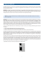
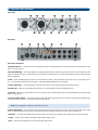
Table of Contents
1. Introduction . . . . . . . . . . . . . . . . . . . . . . . . . . . . . . . . . . . . . . . . . . . . . . . . . . . . . . . . . . . . . . . . . . . . . . . . . . . . . . . . . . . . . . . . . . . . .2
2. What’s in the Box . . . . . . . . . . . . . . . . . . . . . . . . . . . . . . . . . . . . . . . . . . . . . . . . . . . . . . . . . . . . . . . . . . . . . . . . . . . . . . . . . . . . . . . .2
3. About the FireWire 410 . . . . . . . . . . . . . . . . . . . . . . . . . . . . . . . . . . . . . . . . . . . . . . . . . . . . . . . . . . . . . . . . . . . . . . . . . . . . . . . . . . . .3
4. Features and Technical Information . . . . . . . . . . . . . . . . . . . . . . . . . . . . . . . . . . . . . . . . . . . . . . . . . . . . . . . . . . . . . . . . . . . . . . . . .4
5. Minimum System Requirements . . . . . . . . . . . . . . . . . . . . . . . . . . . . . . . . . . . . . . . . . . . . . . . . . . . . . . . . . . . . . . . . . . . . . . . . . . . .5
6. Controls and Connectors . . . . . . . . . . . . . . . . . . . . . . . . . . . . . . . . . . . . . . . . . . . . . . . . . . . . . . . . . . . . . . . . . . . . . . . . . . . . . . . . . .6
7. Hardware Installation . . . . . . . . . . . . . . . . . . . . . . . . . . . . . . . . . . . . . . . . . . . . . . . . . . . . . . . . . . . . . . . . . . . . . . . . . . . . . . . . . . . . .8
8. Driver Installation . . . . . . . . . . . . . . . . . . . . . . . . . . . . . . . . . . . . . . . . . . . . . . . . . . . . . . . . . . . . . . . . . . . . . . . . . . . . . . . . . . . . . . . .8
Win XP . . . . . . . . . . . . . . . . . . . . . . . . . . . . . . . . . . . . . . . . . . . . . . . . . . . . . . . . . . . . . . . . . . . . . . . . . . . . . . . . . . . . . . . . . . . . . . . .8
Win 2000 . . . . . . . . . . . . . . . . . . . . . . . . . . . . . . . . . . . . . . . . . . . . . . . . . . . . . . . . . . . . . . . . . . . . . . . . . . . . . . . . . . . . . . . . . . . . .10
Mac OSX . . . . . . . . . . . . . . . . . . . . . . . . . . . . . . . . . . . . . . . . . . . . . . . . . . . . . . . . . . . . . . . . . . . . . . . . . . . . . . . . . . . . . . . . . . . . .12
Mac OS9 . . . . . . . . . . . . . . . . . . . . . . . . . . . . . . . . . . . . . . . . . . . . . . . . . . . . . . . . . . . . . . . . . . . . . . . . . . . . . . . . . . . . . . . . . . . . .14
9. Hardware Connections . . . . . . . . . . . . . . . . . . . . . . . . . . . . . . . . . . . . . . . . . . . . . . . . . . . . . . . . . . . . . . . . . . . . . . . . . . . . . . . . . . .16
10. Software Control Panel . . . . . . . . . . . . . . . . . . . . . . . . . . . . . . . . . . . . . . . . . . . . . . . . . . . . . . . . . . . . . . . . . . . . . . . . . . . . . . . . .18
Mixer Page . . . . . . . . . . . . . . . . . . . . . . . . . . . . . . . . . . . . . . . . . . . . . . . . . . . . . . . . . . . . . . . . . . . . . . . . . . . . . . . . . . . . . . . . . . .19
Output Page . . . . . . . . . . . . . . . . . . . . . . . . . . . . . . . . . . . . . . . . . . . . . . . . . . . . . . . . . . . . . . . . . . . . . . . . . . . . . . . . . . . . . . . . . .19
Hardware Page . . . . . . . . . . . . . . . . . . . . . . . . . . . . . . . . . . . . . . . . . . . . . . . . . . . . . . . . . . . . . . . . . . . . . . . . . . . . . . . . . . . . . . .21
About . . . . . . . . . . . . . . . . . . . . . . . . . . . . . . . . . . . . . . . . . . . . . . . . . . . . . . . . . . . . . . . . . . . . . . . . . . . . . . . . . . . . . . . . . . . . . . . .21
11. Using the FireWire 410 . . . . . . . . . . . . . . . . . . . . . . . . . . . . . . . . . . . . . . . . . . . . . . . . . . . . . . . . . . . . . . . . . . . . . . . . . . . . . . . . . . .22
General Recording Instructions . . . . . . . . . . . . . . . . . . . . . . . . . . . . . . . . . . . . . . . . . . . . . . . . . . . . . . . . . . . . . . . . . . . . . . . . . .23
Setting the Sample Rate . . . . . . . . . . . . . . . . . . . . . . . . . . . . . . . . . . . . . . . . . . . . . . . . . . . . . . . . . . . . . . . . . . . . . . . . . . . . . . . .23
Adding Effects While Direct Monitoring . . . . . . . . . . . . . . . . . . . . . . . . . . . . . . . . . . . . . . . . . . . . . . . . . . . . . . . . . . . . . . . . . . . .24
Using the Aux Send as a Separate Monitor Mix . . . . . . . . . . . . . . . . . . . . . . . . . . . . . . . . . . . . . . . . . . . . . . . . . . . . . . . . . . . .24
Using the Level Controller Assignments . . . . . . . . . . . . . . . . . . . . . . . . . . . . . . . . . . . . . . . . . . . . . . . . . . . . . . . . . . . . . . . . . . .25
12. Troubleshooting . . . . . . . . . . . . . . . . . . . . . . . . . . . . . . . . . . . . . . . . . . . . . . . . . . . . . . . . . . . . . . . . . . . . . . . . . . . . . . . . . . . . . . . .26
13. Contact Us . . . . . . . . . . . . . . . . . . . . . . . . . . . . . . . . . . . . . . . . . . . . . . . . . . . . . . . . . . . . . . . . . . . . . . . . . . . . . . . . . . . . . . . . . . . .27
14. Product Specs . . . . . . . . . . . . . . . . . . . . . . . . . . . . . . . . . . . . . . . . . . . . . . . . . . . . . . . . . . . . . . . . . . . . . . . . . . . . . . . . . . . . . . . . .28
15. Warranty . . . . . . . . . . . . . . . . . . . . . . . . . . . . . . . . . . . . . . . . . . . . . . . . . . . . . . . . . . . . . . . . . . . . . . . . . . . . . . . . . . . . . . . . . . . . . .29
1. Introduction
Thanks for choosing the M-Audio FireWire 410 Mobile Recording interface. We designed the FireWire 410 to be a professional, portable
solution for getting audio and MIDI in and out of your computer. Using the high-bandwidth IEEE-1394 (FireWire) bus, the FireWire 410 provides
your computer with a high-resolution multichannel audio interface, as well as sixteen channels of MIDI in and out.
With its built-in low-noise mic preamps, XLR mic and 1/4” line level analog inputs, the FireWire 410 gives you a professional quality audio
“front end” for your Digital Audio Workstation. You can connect an instrument or microphone to the FireWire 410’s front-panel inputs, with
switchable phantom power for condenser mics. With its eight line level analog outputs, you can connect to a mixer or surround matrix, or
directly to powered monitors. And with two channels of digital I/O on TOSLink‘s optical and RCA coaxial connectors, you can record to and
from a CD, MiniDisc, or DAT. In all, the FireWire 410 gives you a total of four inputs and ten outputs of connectivity to your computer, in a
rugged but compact package that can travel with you anywhere.
Even if you’re an experienced recordist, please take some time to read through this owner’s manual and familiarize yourself with the FireWire
410’s features and operation. You may also want to refer to your audio software’s documentation to better understand how the FireWire 410’s
features are integrated with the program. Your experience and enjoyment of your FireWire 410 will be greatly enhanced by a good working
knowledge of your audio software.
2. What’s in the Box
Your FireWire 410 package contains the following:
• FireWire 410 Mobile Recording Interface
• Users’ Manual
• Maximum Audio Tools software bundle CD
• Windows and Mac driver software CD
• IEEE 1394 (FireWire) cable – 6 ft.
• 12VDC 1A Power Supply
2
3. About the FireWire 410
The FireWire 410 functions as a four-input, ten-output digital recording and playback interface. A single IEEE 1394 cable connects the FireWire
410 to your computer’s FireWire port. If your computer is not equipped with a native FireWire port, you may purchase a FireWire PCI card at
any computer electronics retailer.
IMPORTANT: The FireWire 410 comes with a high-quality six-pin to six-pin FireWire cable. We strongly suggest you use this cable, or one of
equal quality, for optimum audio performance. If your computer is equipped with a four-pin interface, you will need to obtain a four-pin to
six-pin FireWire cable, available at most computer electronics retailers. Also note that the FireWire 410 requires a six-pin FireWire connection
to supply bus power; if you have a four-pin connection you will need to use the supplied power adapter.
NOTE: Some computer manufacturers may use a different nomenclature to refer to their FireWire connections, such as Sony’s
“iLink”, or simply “1394.”
IMPORTANT: It has come to our attention that problems have been reported with several types of IEEE1394 (“FireWire”) devices, including MAudio FireWire devices. These problems occur when using a 6-pin bus-powered connection when plugging and unplugging external
FireWire devices, when both the computer and external device are powered on. This is commonly referred to as “hotplugging”. In some
cases the FireWire port on the host computer system is rendered permanently inoperable. In other cases the external FireWire device is
rendered permanently inoperable. M-Audio does not want users of M-Audio FireWire products to experience such costly problems.
Therefore, M-Audio must require that users of M-Audio FireWire devices refrain from hotplugging any M-Audio FireWire device. You must
make your FireWire connection while both computer and FireWire device are powered off; then power on.
In case your M-Audio FireWire device was not detected by your computer on startup, try the following troubleshooting options instead of
hotplugging it:
1. Turn your M-Audio FireWire device off, wait 30 seconds then power it on.
2. Put your computer into hibernation mode, wait 30 seconds then reactivate it.
3. Restart the computer (don’t turn it off) while the M-Audio FireWire device remains connected and powered on.
The FireWire 410 is equipped with two analog inputs, available at mic, line or instrument levels on 1/4” TS and XLR connectors. Eight analog
outputs are provided on 1/4” TS connectors, as well as S/PDIF I/O on optical and coaxial connectors. The FireWire 410 gives you high quality
analog and digital I/O in full 24-bit resolution, at sampling rates up to 96kHz for recording and 192 kHz for playback. Its S/PDIF digital I/O
supports output of AC3 and DTS encoded multi-channel digital audio, and its 16-channel MIDI I/O is equipped with a hardware bypass
switch for stand-alone operation.
The FireWire 410’s easy-to-use software control panel provides you with powerful routing and mixing control, creating a virtual ten-channel
output matrix for your audio software.You can route any combination of inputs to any outputs, and each mixer channel supports a virtual
aux send for unprecedented flexibility. You can take advantage of ultra-low latency software monitoring with built-in ASIO drivers, and zerolatency direct hardware monitoring. Two individual headphone outputs with assignable source and separate volume controls give you
added flexibility, and the FireWire 410 can be powered via the FireWire bus for total portability*. Its dual mic/ instrument preamps give you
level control and metering, phantom power, 20dB pads, and a full 66dB of available gain.
* Six-pin FireWire connection only. Use the DC power adapter for four pin FireWire operation.
3
4. Features and Technical Information
• Dual low-noise mic/instrument preamps with gain controls, LED metering, phantom power and 66dB of available gain
• Two analog inputs and eight analog outputs on 1/4” TS jacks
• S/PDIF I/O on TOSLink optical or RCA coaxial connectors
• Supports sampling rates from 32KHz, up to 192KHz
• 2-in/8-out analog I/O at 24 bit resolution, up to 96KHz sampling rate
• 24-bit resolution playback at 192KHz sampling rate on outputs 1 and 2
• Two headphone outputs with assignable source and individual level controls
• Software-assigned rotary encoder for tactile control of monitor levels
• 1 x 1 MIDI I/O with hardware bypass switch for computer-independent operation
• Analog outputs support up to 7.1 surround using your audio software (your software must support surround outputs)
• Frequency response 20-40kHz ± 1dB.
• Signal to noise–104dB
• Dynamic range: 108dB (A-weighted)
• THD + N: 0.00281% @ 0dBFS
4
5. Minimum System Requirements
Important: The FireWire 410 is supported under Windows XP and Windows 2000. The FireWire 410 is not supported under
Windows 98 or Windows ME. In the case of Windows 2000, you must be running SP3 or later. For Windows XP, you must be
running SP1 or later. Visit the Windows update web pages to make certain you have the most current updates and fixes
supplied by Microsoft.
On the Mac, the FireWire 410 is supported under MacOS 9.2 or later, and Mac OSX version 10.1.5 or later. Earlier versions of Mac operating
systems are not supported.
Pentium 3 – 500 MHz or higher
128 MB RAM
DirectX 8.1 or higher
Windows XP (SP1) or Windows 2000 (SP3)
The FireWire 410 is not supported under Windows 98 or Windows ME.
MacOS
Macintosh G3 500 MHz or higher
128 MB RAM (OS 9), 256 MB RAM (OSX)
OS 9.2 or later, or OS 10.1.5 or later
5
6. Controls and Connectors
Front Panel
Rear Panel
Front Panel descriptions
1. MIC/INST INPUTS – Unbalanced Instrument and Mic level inputs. These Neutrik hybrid connectors will accept a standard three-pin XLR
plug or a 1/4” TS connector.
2. MIC/LINE SELECTOR – This switch toggles the unit between Mic/Inst inputs and the rear panel Line Inputs. In the OUT position, Mic/Inst
inputs are selected and active, and the Line Inputs are defeated; in the IN position, Line Inputs are selected and active, and the Mic/Inst
Inputs are defeated.
3. PAD – inserts a 20dB pad into the input circuit, lowering the input level. Use this PAD when the input level of your analog signal is too
hot – as indicated by illumination of the CLIP LED – even with the INPUT GAIN LEVEL at or near minimum.
4. INPUT GAIN LEVEL – This potentiometer controls the input level of its associated analog Mic/Instrument/Line input.
5. SIGNAL LED – When lit, this LED indicates the presence of an audio signal at the associated Mic/Inst input.
6. CLIP LED – When lit, this LED indicates too hot an input signal at the associated Mic/Inst input. The LED will light when the signal is 3dB
below the clipping point.
7. OUTPUT SIGNAL METERS – This dual four-segment LED meter indicates the signal level of the outputs as selected in the FireWire 410’s
control panel. Refer to Section 11, Control Panel Tour, for further details.
Note: When playing back at 192KHz, the LED meter is inactive.
8. LEVEL CONTROLLER – This continuous rotary encoder regulates the signal level of the buses as selected in the FireWire 410’s control
panel. The default setting is OUTPUT, which is the most likely choice for general monitoring. The other options available are:
•SW Return – The level of the FireWire 410’s ten virtual outputs, returning from your digital audio software to the control panel’s Mixer
•Output – The level of the FireWire 410’s eight analog and two digital outputs
•Input – The level of the FireWire 410’s two analog and two digital inputs
6
•Phones – The level of the FireWire 410’s headphone outputs
•Aux Send – The level of the FireWire 410’s AUX SEND bus, as controlled by the Input Channel AUX SENDS in the FireWire 410 control panel
Refer to Section 11, CONTROL PANEL, for further details.
9. HEADPHONE OUTPUTS – Each of these output jacks accepts a standard 1/4” stereo TRS headphone connector. The program signal
is identical on both outputs, with individual levels regulated by the HEADPHONE LEVEL CONTROLS. The default source selection for the
headphone output is identical to line outputs 1/2. (Refer to Section 11, CONTROL PANEL, for further details.)
10. HEADPHONE LEVEL CONTROLS – Each of these potentiometers controls the output level of its associated headphone output.
11. S/PDIF IN AND OUT LEDS – The S/PDIF IN LED will glow steadily to indicate the presence of a valid S/PDIF signal at the selected S/PDIF
input. The S/PDIF IN LED will flash to indicate the presence of a valid S/PDIF signal at the incorrect S/PDIF input.
The S/PDIF OUT LED will glow steadily to indicate the presence of a valid S/PDIF signal at either S/PDIF output. (The S/PDIF output is always
sent to both the optical and coaxial outputs simultaneously.)
12. MIDI THRU SWITCH – When this switch is in the IN position, the FireWire 410’s MIDI IN and MIDI OUT ports function in bypass mode;
that is, they do not require a host software application, but function as simple hardware MIDI connections. This mode can be used whether
the FireWire 410 is powered on or off.
13. POWER SWITCH AND LED – Turns the FireWire 410 on and off.
Note: When the FireWire 410 is powered OFF, the blue POWER LED will flash if it senses a valid FireWire connection to a running
computer. When the LED is flashing, the unit is in “low-power” mode, and will allow a FireWire peripheral connected to the
FireWire 410 to continue to function. You must turn the FireWire 410 ON (blue POWER LED glows steadily) for the unit to function.
14. PHANTOM POWER SWITCH AND LED – When this switch is in the IN position, +48V phantom power is supplied to both XLR inputs.
Phantom power is required for most condenser microphones.
NOTE: While most modern dynamic microphones are unaffected by phantom power, many ribbon mics and some older
dynamic microphones may be damaged if phantom power is applied to them.
Rear Panel Descriptions
15. POWER SUPPLY CONNECTOR – Connect the 12VDC 1A power supply here when using the FireWire 410 with a four-pin FireWire
connection. Use only the power supply provided with the unit or a power supply with an equivalent value.
16. MIDI IN AND MIDI OUT CONNECTORS – MIDI input and output on standard 5-pin DIN connectors. These connections will allow MIDI
information to pass directly from input to output when the MIDI THRU button is pressed.
17. FIREWIRE CONNECTORS – Dual FireWire (IEEE-1394) inputs allow you to connect one to your computer and another to an external
device. We recommend connecting only self-powered devices to these inputs. Bus powered devices may affect your audio performance.
18. S/PDIF COAXIAL IN AND OUT CONNECTORS – S/PDIF digital input and output on coaxial RCA connectors. The digital input is
selected via the FireWire 410’s control panel, while the digital output will be sent to both coaxial and optical outputs. Coaxial is the default
setting in your control panel, so the coaxial input (only) is active until another selection is made.
19. S/PDIF TOSLINK IN AND OUT CONNECTORS – S/PDIF digital input and output on optical TOSLink connectors. The digital input is
selected via the FireWire 410’s control panel, while the digital output will be sent to both optical and coaxial outputs.
20. LINE OUTPUTS 1 – 8 – These are unbalanced analog outputs on standard 1/4” TS connectors at 10dB line level. These outputs will
support standard two-channel stereo, as well as surround modes up to 7.1. (Your audio software must support multiple surround outputs.)
When monitoring two-channel stereo program, outputs 1 and 2 are the default outputs; any or all output pairs may be selected in the
FireWire 410’s control panel. You may also use the eight outputs to send individual or grouped channels to a mixing console.
21. LINE INPUTS 1 AND 2 – These are unbalanced analog inputs on standard 1/4” TS connectors at –10dB line level. They are parallel
to the front-panel analog inputs, and are functional only when the front panel mic/line switch is in the “in” position.
7
7. Hardware Installation
NOTE: Do NOT connect the FireWire 410 to your computer until you have run the installer program and shut down the system.
Once you have powered down the computer, you may connect the FireWire 410 to your host computer’s FireWire port. See
Section 8, Driver Installation for further details.
Note: For the latest driver updates please check www.m-audio.com
8. Driver Installation
Win XP
NOTE: Do NOT connect the FireWire 410 to your computer until you have run the installer application and shut down the system..
Insert the FireWire 410 driver CD-ROM into your computer. From the Start menu, select “Run…” then click the Browse button. Browse to the
CD drive and open firewire 410 folder and then click on the FW410_”...” Setup.EXE icon.
The installer will copy the necessary files to your computer’s hard drive.
During the installation, you will be prompted with a message warning that the driver software has not passed Windows Logo testing. Select
Continue Anyway and proceed with the installation.
8
The installer will prompt you to enable DVD/CD performance enhancement settings. In most cases you should leave these in their default
(selected) settings.
Once the installer has finished copying the files, you will see the Installation Complete screen.
You will then be prompted to shut down your computer.
After the computer has powered off, connect the FireWire 410 to your computer’s FireWire port and power it on. Once the FireWire 410 is
connected, power on your computer. When the operating system loads, the Found New Hardware Wizard will open.
Choose the default selection, “Install the software automatically.” Click Next. Windows will locate and install the FireWire 410 Bootloader files.
9
Once the Bootloader installation is complete, Windows will locate the FireWire 410 driver files. The New Hardware Wizard will run a second
time to install the FireWire 410 driver software.
Once again, select the default selection, “Install the software automatically” and click Next. Windows will install the driver files. You will again
be prompted by the Windows Logo testing notice – again, click Continue Anyway and proceed with the full installation.
When you see the “M-Audio FireWire 410 Installed Successfully” screen, click Finish to complete the installation.
Your FireWire 410 is now ready to use.
You will see the M-Audio FireWire 410 control panel icon in your system tray (lower right corner of your desktop). Click on the icon to open
the control panel.
Win 2000
NOTE: Do NOT connect the FireWire 410 to your computer until you have run the installer application and shut down the system.
Insert the FireWire 410 driver CD-ROM into your computer. From the Start menu, select “Run…” then click the Browse button. Browse to the
CD drive and open firewire 410 folder and then click on the FW410_”...” Setup.EXE icon.
The installer will copy the necessary files to your computer’s hard drive. During the installation, you will be prompted with a message
warning that the driver software has not passed Windows Logo testing. Select Continue Anyway and proceed with the installation.
The installer will prompt you to enable DVD/CD performance enhancement settings. In most cases you should leave these in their default
(selected) settings.
10
Once the installer has finished copying the files, you will see the Installation Complete screen.
Once the installer has finished copying the files, you will be prompted to shut down your computer.
After the computer has powered off, connect the FireWire 410 to your computer’s FireWire port and power it on. Once the FireWire 410 is
connected, turn on your computer. After the operating system loads, the Found New Hardware Wizard will open.
Choose the default selection, “Install the software automatically.” Click Next.
Windows will locate and install the FireWire 410 Bootloader files. You will again be prompted by the Windows Digital Signature warning
screen. Once again, select Continue Anyway and proceed with the installation.
Once the Bootloader installation is complete, Windows will locate the FireWire 410 driver files.
11
Once again, select the default selection, “Install the software automatically” and click Next. Windows will install the driver files. You will again
be prompted by the Windows Digital Signature notice – once again, click Continue Anyway and proceed with the full installation.
When you see the Completing New Hardware Wizard screen, click Finish to complete the installation.
Your FireWire 410 is now ready to use. You will see the M-Audio FireWire 410 control panel icon in your system tray (lower right corner of your
desktop). Click on the icon to open the control panel.
Mac OSX
NOTE: Do NOT connect the FireWire 410 to your computer until you have run the installer application and shut down the system.
1. Insert the FireWire 410 driver CD into your CD-ROM drive and open the CD to view its contents.
2. Double click the M-Audio FireWire 410 Installer.dmg file. An icon labeled FIREWIRE 410 will appear on your desktop.
12
3. Double click on the FireWire 410 icon. The file M-Audio FireWire 410 Installer.mpkg will appear. Double click on the installer file.
4. You will need your Administrator Password for the next step. To continue, click the lock icon in the lower left corner of the window that
states, “Click The Lock To Make Changes." In OSX version10.2.2 this authentication dialog will automatically appear.
5. Enter your password and click "OK."
13
6. The next window "Welcomes You..." to the installation process. Click "Continue."
7. Select your OS X hard drive. Click "Continue."
8. When prompted, click "Upgrade" to continue.
9. When prompted, click "Continue Installation."
10. When prompted, click "Shut Down" to finish the installation.
11. After the computer has powered off, plug the FireWire 410 into your computer’s FireWire Port and turn it on. Once the FireWire 410 is
connected, Turn on your computer.
12. Once the operating system loads, go to "System Preferences" in the Apple Menu. Select the "Sound" preference panel, and click the
"Output" tab. Select "M-Audio FireWire 410" to choose the FireWire 410 as your default output device.
Mac OS9
NOTE: Do NOT connect the FireWire 410 to your computer until you have run the installer application and shut down the system.
14
1. Insert the FireWire 410 driver CD into your CD-ROM drive. AutoRun will open the CD and allow you to view its contents.
2. Double click on the “M-Audio FireWire 410 Installer” icon.
3. Click “Continue” in the M-Powered screen.
4. Read the instructions screen, then click “Continue.”
5. Select your install location, or just choose the default, OS 9 boot drive. Click Continue.
6. You will be prompted to shut down your computer. Click “Shut Down.”
7. When your computer has powered off, connect the FireWire 410 to your computer’s FireWire port and turn it on. Once the FireWire 410 is
connected, turn on your computer.
8. Once the operating system loads, go to Control Panels, select Sound, then select the Output tab. Click on M-Audio FireWire 410 to select
FireWire 410 as your default audio device.
15
9. Hardware Connections
ATTENTION: You must shut down your computer any time you wish to connect or disconnect the FireWire 1814 from the system. Failure to
do so may cause damage to your computer’s or FireWire 1814’s FireWire ports.
Audio
Connect the FireWire 410’s outputs to your amplifier, powered monitors or surround system. For two-channel stereo operation, the default
outputs are channels 1 and 2. (You may change this in the FireWire 410 control panel if you desire.) For multi-channel surround output,
connect up to eight powered monitors to the FireWire 410’s eight analog outputs.
If you are monitoring through headphones, connect one or two sets of headphones to the FireWire 410’s headphone outputs.
Connect your microphones, instruments or other line level analog sources to the FireWire 410’s front or rear panel analog inputs. Note that
the front and rear panel inputs do not function simultaneously. To use the mic/inst inputs, the mic/line switch must be in the “out,” or “mic” position.
Connect your S/PDIF digital devices to the FireWire 410’s optical or coaxial digital I/O. Note that only one digital I/O (optical or coaxial) may
be active at a time; the active digital I/O is selected in the FireWire 410 control panel.
16
MIDI
Connect your MIDI device’s MIDI Input to the FireWire 410’s MIDI Output. Connect your MIDI device’s MIDI Output to the FireWire 410’s MIDI Input.
Use the front-panel MIDI Thru switch to operate the FireWire 410 in stand-alone mode. In this mode connection to a host computer is not
necessary to pass MIDI information.
Shown in the illustration below is a MIDI controller keyboard plugged into the FireWire 410’s MIDI input. A MIDI sound module is connected
to the FireWire 410’s MIDI output.
17
10. Software Control Panel
The FireWire 410’s driver software provides a simple yet powerful interface with your computer and Digital Audio Workstation software. The
control panel gives you a multi-channel software mixer with ten virtual outputs (in five stereo pairs) from your audio software. Each output
pair may be routed to any of the FireWire 410’s eight analog or two digital outputs. In addition, two software auxiliary sends are available
per stereo pair.
The FireWire 410 control panel is installed in your system when you complete the driver installation procedure. To open the control panel:
In Windows – A tiny “M,” which is the M-Audio logo, will by placed in the system tray, generally located at the bottom of your Windows
desktop. Double click this icon to open the control panel.
On the Mac – The FireWire 410 control panel can be found under the Apple menu.
While the FireWire 410 control panel gives you a great deal of control, you may find that the default settings work just fine for your needs.
Depending on how you record, you may never have to make an adjustment to these settings. Just to be safe, though, we’ll go through the
control panel in great detail and explain all of the user controls.
NOTE: The FireWire 410 control panel can also be opened from an ASIO compliant music program’s audio setup page.
Global Menus
The following control panel features are available on all pages of the control panel:
MIXER SETTINGS – The RESET button returns the control panel settings to their default values. These default values can be found in Section
14, Product Specifications.
The LOAD, SAVE and DELETE buttons will open a Windows or Mac file dialog box within your audio application, with the corresponding load,
save or delete function selected.
LEVEL CONTROLLER ASSIGNMENT – This section allows you to choose which group of MIXER or OUTPUT faders the front-panel LEVEL
CONTROLLER rotary encoder is addressing. The Level Controller in the FW410 Control Panel is a software representation of the hardware Level
Controller on the front panel, and will follow the controller assignment made here. The encoder can offer tactile control for the following:
• SW RETURN – The levels of the five virtual stereo pairs returning from your computer’s audio workstation software
• OUTPUT – The levels of the FireWire 410’s eight analog and two digital outputs
• INPUT – The levels of the FireWire 410’s two analog and two digital inputs
• PHONES – The levels of the FireWire 410’s headphone outputs. Note that the levels of each individual headphone output is still controlled
via its associated front-panel level control knob.
• AUX SEND – The levels of the L and R virtual AUX SEND buses.
When you first click on one of the group assignments listed above, the CTRL buttons for that entire group assignment will activate. For
example, if you select PHONES, the CTRL button will appear over the PHONES faders in the output channel.
This group assignment can be modified by clicking on an active CTRL button and deselecting the associated channel faders. Changes to the
LEVEL CONTROLLER position will then affect only the selected channel faders. The control panel will remember these modified assignments
when you click to another LEVEL CONTROLLER assignment group, then click back to the group with modified assignments.
MAIN OUTPUT – These two buttons provide immediate access to MUTE or DIM the overall monitor output levels. Pressing the MUTE button
(the button turns red) will cease audio output to all of the FW410’s hardware outputs. This is useful when you wish to switch back and forth
between monitoring with headphones and monitoring with your speakers. Pressing the DIM button (the button turns green) will lower the
listening level of the hardware outputs by 20dB. This is useful if, for example, you want to have quick conversation without losing the groove,
then return to your previous listening level.
MULTIPLE UNITS – The control panel also shows a “Unit 1” designation. Future updates of the FireWire 410 software drivers will allow you to
chain multiple units together for increased I/O. Clicking on a unit icon will activate the control panel for that particular unit, displaying its
control panel settings.
Presently only a single FireWire 410 is supported. We suggest you check the M-Audio website for information on FireWire 410 driver updates.
18
Mixer Page
The MIXER PAGE provides output routing and control of the FireWire 410’s analog and digital inputs, as well as the ten virtual channels
returning from your Digital Audio Workstation software.
SOFTWARE RETURNS – The MIXER PAGE provides access to ten virtual audio “returns” from your audio application. These returns are
available in stereo pairs, and are labeled 1/2 SW RTN; 3/4 SW RTN; 5/6 SW RTN; 7/8 SW RTN; and SPDIF SW RTN. These returns will appear
in the program’s output mixer settings as available audio outputs.
Most likely, you will control the output monitor levels from your music program’s mixer, and will want to keep these sliders at their maximum
level. However, you may find it convenient to adjust them here, if you are, for example, setting up a balance between input levels and SW
RTN levels.
HARDWARE INPUTS – The MIXER PAGE also provides software level control for direct monitoring of the FireWire 410’s analog and S/PDIF
digital inputs. These pairs are labeled ANALOG IN and SPDIF IN.
It may be important to note that the input channel default settings have NO Output Routings selected (see the next section for more
information). Monitoring these inputs may be set up from within your music program, or you may make an Output Routing selection and
then set the slider level for monitoring. See “Monitoring Your Inputs for Recording” in Section 11of this manual for more information.
OUTPUT ROUTING – Each stereo pair may be assigned to any of the FireWire 410’s analog or digital outputs by clicking on the output button
of the desired output pair. These are labeled 1/2; 3/4; 5/6; 7/8; and SPD (which represents “S/PDIF”). Any or all output pairs may be selected
(the button turns blue when active) for each Mixer input channel pair. These channels’ output signals appear on the selected outputs in the
control panel OUTPUT PAGE. If multiple Mixer channels are assigned to the same output pair, the signals will be summed at the assigned
output. Note that clipping of summed signals is possible, so keep an eye on your output level meters when summing mixer channels.
AUX SEND – Each of these stereo pairs also provides two virtual AUX SEND controls. Using these AUX SENDS you can create a separate
sub-mix, which can be useful as a headphone mix or effects send. To use the AUX SENDS, click on a send knob and drag upward or
downward. These AUX SENDs levels feed the AUX SEND Master channel on the Output page. The AUX SEND mix can be routed to any pair
of the FireWire 410’s outputs via the OUTPUT PAGE by clicking the MAIN button on that channel, thereby switching the output channel from
the main bus to the AUX bus.
STEREO LINKING - Input levels from each virtual software return are controlled by software faders; pairs can be linked for stereo operation
by clicking the channels’ LINK button. The button turns blue when active. Once the channel is linked, grabbing and moving one fader will
move both faders in unison.
MUTE BUTTON - Selecting the MUTE button (the button turns red) will cause that channel pair to cease audio output. Deselecting the MUTE
button will resume audio output on that channel pair.
SOLO BUTTON – Selecting the SOLO button (the button turns yellow) will cause all other channels to cease audio output; deselecting the
SOLO button will resume audio output on all channels. Multiple solo selections are possible.
PANNING - The analog and digital input channel pairs also offer virtual PAN pots. As with any typical mixer, the PAN works in conjunction
with the output assign buttons to enable you to route the signal as you wish.
METERING - At the bottom of the MIXER PAGE, software level meters are provided for each of the FireWire 410’s five output buses, as well as
the AUX BUS. This is provided as a quick reference to what’s going on in the Output page.
19
Output Page
The OUTPUT page provides you with control over each of the FireWire 410’s analog and digital outputs, as well as that of the AUX BUS and
HEADPHONES Bus.
OUTPUT CHANNELS – Virtual FADERS control the individual channel output levels. The output faders correspond to their respective analog
and digital (hardware) outputs. When the MAIN/AUX button is set to MAIN, the OUTPUT CHANNEL gets its signal from the bus assignments
selected on the MIXER PAGE. (See MAIN/AUX BUTTON, below.)
BALANCE CONTROLS – The BAL control allows you to adjust the balance of the associated pair’s stereo output.
LINKING - Stereo pairs can be linked together with the LINK button above each channel pair. Once the channel is linked (the button turns
blue), grabbing and moving one fader will move both faders in unison.
MAIN/AUX BUTTON – When the MAIN/AUX button is in the MAIN position (the button turns blue), the associated analog or digital outputs
carry their respective bus signals, as determined by the routing selected on the MIXER PAGE:
• outputs 1/2 Out carries signals routed to bus 1/2
• outputs 3/4 Out carries signals routed to bus 3/4
• outputs 5/6 Out carries signals routed to bus 5/6
• outputs 7/8 Out carries signals routed to bus 7/8
• outputs SPDIF OUT carries signals routed to bus SPD
When the MAIN/AUX button is in the AUX position (the button turns green), the associated analog or digital output pair carries the signal
routed to the AUX L and AUX R buses.
MUTE BUTTON - Selecting the MUTE button (the button turns red) will cause that channel pair to cease audio output. Deselecting the MUTE
button will resume audio output on that channel pair.
SOLO BUTTON – Selecting the SOLO button (the button turns yellow) will cause all other channels to cease audio output; deselecting the
SOLO button will resume audio output on all channels. Multiple solo selections are possible.
AUX OUTPUT MASTER CHANNEL – This Aux Send Master channel controls the output functions of signals routed to the AUX L and AUX R
buses. Both channel faders can be linked together with the LINK button, and the PAN control allows you to pan the output anywhere within
the assigned stereo pair. The BAL control allows you to adjust the balance of the stereo signal.
When using the AUX SENDS in conjunction with the AUX OUTPUT CHANNEL, you must select an output to be the Aux output by setting the
MAIN/AUX switch on that channel to the AUX position. See section 11, Adding Effects While Direct Monitoring and Using the Aux Send As a
Separate Monitor Mix, later in this manual.
CTRL BUTTON – The CTRL button will appear and be active over the output channels selected under the right panel’s LEVEL CONTROLLER
ASSIGNMENT. (Example: If the AUX OUTPUT is selected under the LEVEL CONTROLLER ASSIGNMENT, the CTRL button will appear over the AUX
OUTPUT CHANNEL faders.) For more information, see LEVEL CONTROLLER ASSIGNMENT in the GLOBAL MENUS section below.
AUX CHANNEL PANNING – The individual AUX sends can be panned within the stereo output pair they are assigned to. Note that if you
wish to use the AUX send as a mono send, you should pan these controls to the <C> position, which is “center panned.”
AUX CHANNEL MUTE - Selecting the AUX MUTE button (the button turns red) will cause the AUX CHANNEL to cease audio output. Deselecting
the MUTE button will resume audio output.
HEADPHONE OUTPUT CHANNEL – This channel controls the functions of the FireWire 410’s headphone bus. Both channel faders can be
linked together with the LINK button, and the BAL control allows you to adjust the stereo balance of the headphone output.
20
HEADPHONE MONITOR ASSIGNS – You can monitor any of the FireWire 410’s output buses via the Headphones bus. Using the MONITOR
ASSIGNS you can select any or all of the five output buses to route to the headphones. Note that this single source selection applies to both
of the headphone output jacks—both headphone outs receive the same source.
HEADPHONE MAIN/AUX BUTTON – When the MAIN/AUX button is in the MAIN position, the headphone bus monitors the outputs selected
by the MONITOR ASSIGNS, above. When the MAIN/AUX button is in the AUX position, the headphone bus monitors the signal routed to the
AUX L and AUX R buses.
HEADPHONE MUTE BUTTON - Selecting the MUTE button (the button turns red) will cause the headphone channels to cease audio output.
Deselecting the MUTE button will resume audio output on the headphone channels.
METERING – At the bottom of the OUTPUT PAGE, software level meters are provided for the FireWire 410’s analog and digital inputs, as well
as for the ten virtual software return channel inputs. This is provided as a quick reference to what’s going on in the Mixer page.
Hardware Page
The hardware page gives you access to important information and functions of the FireWire 410.
SAMPLE RATE DETECTED – This field displays the currently-detected sample rate from the currently selected sync source.
ASIO/WDM BUFFER SIZE – In this field you can select the buffer size you wish to work with. Smaller buffer sizes result in lower latency (the
time it takes for your input signal to pass through your audio software and appear at the outputs), but may not function well with slower
systems. The default buffer size setting is 256. This setting may adequately serve your purposes, but if you wish to, you can experiment with
lower settings. If you experience stuttering or crackling in your audio playback, try using a larger buffer size.
SYNC SOURCE – This field allows you to choose between the FireWire 410’s INTERNAL clock and an EXTERNAL clock source. INTERNAL selects
the incoming clock from the 1394 bus as set by your audio software. Use EXTERNAL when you wish to record from the S/PDIF inputs, or
otherwise lock to the sample rate from an external S/PDIF source.
S/PDIF INPUT – This field selects between TOSLink optical and RCA coaxial input source. Note that both optical and coaxial outputs are
available simultaneously, but only one input source may be used at a time.
FIRMWARE INFO – This field displays the current firmware version of your FireWire 410.
About
This page contains information on your hardware and current driver software versions. This information may be helpful should you ever have
the occasion to call for technical support. Clicking the M-AUDIO logo in the lower left hand corner will link you directly to our website, if you
are currently online.
21
11. Using the FireWire 410
The following sections address a number of real-life situations that you may encounter while using your FireWire 410. These brief tutorials
should help guide you. Also check the M-Audio website from time to time for other tutorials or FAQs that might arise.
Setting Up Your Record Levels
Using the Mic/Inst Inputs – Connect your microphone or instrument output to the FireWire 410’s front panel Mic/Inst inputs. Make sure the
associated channel’s MIC/LINE switch is set to the OUT position. If you are using a condenser microphone, be certain to activate the
PHANTOM POWER switch. Adjust the channel’s INPUT GAIN to achieve a steady green SIGNAL LED without triggering the red CLIP LED.
You will then want to route the input signal to your DAW’s inputs. Refer to the section below on monitoring your inputs, and to your software’s
documentation, for more information.
Using the Line Inputs – Connect your line level output to the FireWire 410’s rear panel LINE INPUTS. Make sure the associated channel’s
MIC/LINE switch is set to the IN position.
The signal level that you receive at the line inputs will be the signal level that you record. Any adjustments to that signal level must be made
at the source. If you have an output level control on the device that you’ve connected to the FireWire 410’s line inputs, adjust that output level
control to change the recording level. Most recording software will allow you to add gain to a recording that is made at a level that is initially
too low, but be careful that the recording level is not reaching digital clipping (going into the red) while recording.
You will then want to route the input signal to your DAW’s inputs. Refer to the section below on monitoring your inputs, and to your software’s
documentation, for more information.
Using the S/PDIF Input – Connect your S/PDIF digital output to the FireWire 410’s rear panel digital inputs. If your S/PDIF connection is via
RCA connectors, choose the coaxial input; if it is an optical connection, choose the optical input.
Make sure that “external” is selected as the sync source in your FireWire 410 control panel’s HARDWARE page.
The signal level that you receive at the S/PDIF input will be the signal level that you record. In most cases, this level cannot be modified at
the source.
Monitoring Your Inputs For Recording
The FireWire 410 supports ASIO direct monitoring, ASIO tape-type monitoring and WDM/MME input monitoring. The FireWire 410 also
supports direct monitoring independent of the software’s monitoring capability.
ASIO direct monitoring – Most applications that support ASIO 2.0, support ASIO direct monitoring. In ASIO direct monitoring mode, your
audio application sends the input signal directly back to the FireWire 410’s outputs, without passing through the application itself. The
advantage is that there is no latency from passing through your audio software. However, since the audio is bypassing the software, you
can not add effects or EQ plugins to the signal being monitored.
ASIO direct monitoring, when enabled, will allow you to control the monitor levels of the FireWire 410’s inputs directly from the program. Once
you have assigned an input channel in the music software’s mixer to a FireWire 410 input, the music software’s mixer will take control of the
FireWire 410 control panel mixer’s input channels.
As mentioned, while the advantages to this type of monitoring are obvious (no latency), the inability to add effects can be seen as a
drawback. That’s why we created the AUX SENDS in the FireWire 410 control panel’s Mixer. These AUX SENDS will allow you to add effects
while direct monitoring. See the section on Adding Effects While Direct Monitoring for more information.
If your audio application supports ASIO direct monitoring, you can enable it in your DAW’s ASIO or audio control panel. Please refer to your
audio software’s documentation for additional information.
ASIO tape-type monitoring – ASIO also supports tape-type monitoring (sometimes referred to as “tape-machine” monitoring). In this case,
the input signals are monitored through your audio software’s mixer. Normally, the input monitoring is active when the program is in Record
or Record-armed modes; when the program is in playback mode, the input monitoring is disabled, allowing you to hear the recorded audio.
This is useful for listening to the take you just recorded, without having to disarm the input channels. Although you can monitor your inputs
with effects and EQ plugins, a small amount of latency is introduced by monitoring through your software. The FireWire 410 supports the
ultra-low latency ASIO 2.0 standard, however your actual latency is influenced by a number of factors including your computer hardware,
processor speed and selected buffer size both in your FireWire 410 control panel and your music software.
22
If your audio application supports ASIO tape-type monitoring, you can enable it in your DAW’s ASIO or audio control panel. Please refer to
your audio software’s documentation for additional information.
WDM input monitoring – If you are running a WDM-compliant application, the FireWire 410 supports input monitoring through your audio
software. In most cases WDM offers extremely low latency monitoring, even when using plugin effects and EQ, very similar to ASIO tapetype monitoring.
If your application supports WDM and direct monitoring, you may enable it in your DAW’s audio control panel. Please refer to your audio
software’s documentation for additional information.
Other direct monitoring — If you are running a program that is not ASIO compliant or does not have WDM input monitoring (such as Cakewalk
9 or other earlier versions), you can still take advantage of the FireWire 410’s ability to directly monitor the analog and S/PDIF inputs using
the FireWire 410 control panel Mixer. Even if your program does have ASIO tape-type or WDM input low-latency monitoring, you may choose
to direct monitor the FireWire 410’s inputs in this fashion, and enjoy zero-latency monitoring.
With ASIO direct monitoring, the audio software will take over control of the FireWire 410 Mixer’s input channels. With this form of direct
monitoring, you must control the FireWire 410 Mixer’s input channels manually. Here’s how:
1. Open your audio software and the FireWire 410 control panel.
2. In the FireWire 410 control panel, click the MIXER tab. (Let’s assume that we’re recording with the analog inputs, and that we’re monitoring
from the line outputs 1/2 in stereo.) Assign the “analog in” channels to “1/2,” and bring up the channel’s faders until you begin to hear the
source that’s connected to the line inputs. See the previous section, Adjusting the Input Levels for more information.
3. In your audio software, enable tracks to record from the FireWire 410 ANALOG INPUTS 1/2. Either lower the program’s monitor faders for
those channels to full attenuation, or mute those channels so that you don’t hear the tracks from the program while recording. (Remember,
we’re direct monitoring the inputs of the FireWire 410.)
4. If you have tracks already recorded in your audio software that you wish to overdub to, play those tracks and get a monitor balance
between the tracks you are recording and the tracks already recorded by adjusting the ANALOG IN faders in the FireWire 410 control panel
MIXER page.
If you find that you need to fine-tune that monitor balance by going back and forth between your audio software and the FireWire 410 control
panel, you might want to assign the LEVEL CONTROLLER to control the ANALOG IN faders in the FireWire 410 control panel, at least while
you’re setting up for recording. For more information, see the section, Using the Level Controller Assignments.
As mentioned, while the advantages to this type of monitoring are obvious (no latency), the inability to add effects can be seen as a
drawback. That’s why we created the AUX SENDS in the FireWire 410 control panel’s MIXER. These AUX SENDS will allow you to add effects
while direct monitoring. See the section, Adding Effects While Direct Monitoring for more information.
General Recording Instructions
The FireWire 410’s analog and digital inputs will appear as inputs in your audio software. Depending on your chosen application, these may
be labeled as ASIO inputs, WDM inputs or CoreAudio inputs. Typically, for example, in an ASIO-based application (e.g., Cubase, Nuendo,
Digital Performer 3) the FireWire 410’s inputs will appear as:
FireWire 410 Analog input 1
FireWire 410 Analog input 2
FireWire 410 S/PDIF input L
FireWire 410 S/PDIF input R
If you’re using ANALOG IN 1 OR 2, activate the input labeled as Analog Inputs in your audio software’s input mixer. If you’re using the S/PDIF
INPUTS, you must choose the correct S/PDIF input in the control panel’s HARDWARE page. Then choose an available track in your audio
software and route the input signal to it. Refer to your audio software’s documentation for further information.
Setting the Sample Rate
In most cases, you will want to set the sample rate from within your audio software. When the SYNC SOURCE in the HARDWARE page of the
FireWire 410’s control panel is set to Internal, it will receive the sample rate from your audio application. If, however, you are recording a
digital source via the S/PDIF inputs, you will want to set the SYNC SOURCE to External. This will allow the incoming digital source to control
the sample rate.
23
Adding Effects While Direct Monitoring
This is an important feature of the FireWire 410, and something that sets if apart from many other audio interfaces. Direct monitoring is a
way of avoiding the latency inherent in through-the-program type monitoring, especially when building up a large number of tracks (where
buffer size and latency increase). The AUX SENDS in the FireWire 410 control panel allow you to add effects to the direct monitored signal.
You must have an outboard effects unit with a S/PDIF digital input and output (fairly common on the market today), an effects unit with S/PDIF
digital out only, or an A/D converter that would allow you to plug the output of the effects unit into the FireWire 410’s S/PDIF input. The
following step-by-step instructions give you a basic setup, and continue on to an advanced setup for adding and monitoring effects.
NOTE: In this example, we would leave the sync source selection in the control panel’s HARDWARE page set to “internal.”
The outboard effects unit will get its clock from the FireWire 410’s S/PDIF OUT, and therefore will lock to the internal clock.
When the effect unit returns to the S/PDIF Input, the S/PDIF Input should be in sync with the internal clock.
1. Connect the FireWire 410’s S/PDIF Out to the S/PDIF input of your outboard effects unit. In the FireWire 410’s OUTPUT page, click on the SPDIF
OUT channel’s MAIN/AUX switch so that it displays AUX.
2. Since we’re going to be monitoring the effect from the S/PDIF input, we must assign the SPDIF IN channel in the FireWire 410 MIXER page
to a destination. Select “1/2” as the destination, so that the effect is mixed in with other signals being monitored.
3. Set up your FireWire 410 to record with the analog inputs, using the instructions under the Setting Up Your Record Levels section, and either
the ASIO Direct Monitoring or Other Direct Monitoring sections.
4. Let’s assume that you are using only the 1st ANALOG IN for recording (maybe a guitar on channel 1). After you have set up a reasonable
monitor level using the level fader on the Mixer’s ANALOG IN and panned the channel (most likely center), add some level to the AUX L
control. That signal is being sent to the AUX OUTPUT MASTER channel, and then to the sPDIF OUT. Since we’re adding an effect to a mono
instrument, set the AUX OUTPUT MASTER channel’s PAN knobs to <C>, or center panned.
As you play the guitar, you should start to see level appear on the AUX OUTPUT MASTER channel as you add level to AUX L control on the
ANALOG IN. You should also start to see level appearing at the input of your effects unit, and hearing that effect level at the FireWire 410’s
SPDIF IN. You can make adjustments to that monitor level using the SPDIF IN channel’s level faders.
Now for the advanced setup. We’ve added an effect to the instrument that we’re recording and direct monitoring. That’s fine for recording,
but we might want to hear that same effect when we are playing back—at least while the recording process is going on. Once you’re done
recording, you might want to disconnect the outboard effects unit, reset your FireWire 410 Mixer, and then use the software plug-in effects
from within your audio software.
Here’s a suggestion for how you can hear the same effect on the guitar you are recording as you hear when playing back the track and
evaluating the performance.
1. Whichever track you are recording to, set that track’s output to FW410 ANALOG 7/8.
2. In the FireWire 410 MIXER, set the destination on SW RTN 7/8 to 1/2. Then, match the level and the pan setting on SW RTN 7 to the ANALOG
IN channel 1. Also, match the level of the AUX L controls for both of those channels.
This way, when you play back a track that you’ve just recorded, you’ll hear it in exactly the same way as you did while recording. This is very
useful for both the artist and the producer, and is generally better for judging the performance than having to shift your perception to listening
to the track without an effect or with a different effect (such as one provided by a software plug-in).
NOTE: If your effects unit does not have a S/PDIF input as well as output, you may substitute the FireWire 410 LINE OUT
7/8 for the S/PDIF output in this example. In that case, you will have to set the sync source selection in the control panel’s
HARDWARE page set to “external.” The FireWire 410 will have to slave to the clock signal that the effects unit is sending,
while that effect unit may be limited in the number of possible sampling rates.
Using the Aux Send as a Separate Monitor Mix
The AUX SEND can also be used to create an alternate monitor mix that is sent to a headphone amplifier. Sometimes the artist wants to hear
a different mix than the recording engineer, perhaps one with louder rhythm tracks or a quieter piano track—whatever they need to inspire
their performance.
1. In the FireWire 410’s OUTPUT page, choose either the 7/8 OUT or the SPDIF OUT for your send to the headphone amp. Click that channel’s
MAIN/AUX SWITCH so that it displays AUX. Connect that output to your headphone amp, and plug in headphones to monitor with.
24
2. In the FireWire 410 Mixer, add level to the AUX L and AUX R controls to create the headphone mix. Whichever channels are playing back
into the Mixer, whether they’re SW RTNS, ANALOG IN or SPDIF IN, assign an appropriate aux send level to this alternate mix.
That’s about it! You can make changes to the fader levels for a control room mix, and at the same time adjust the AUX SEND levels to meet
the artist’s desires. Everyone’s happy, a great recording is made, everyone becomes famous and lives happily ever after.
Using the Level Controller Assignments
The LEVEL CONTROLLER on the FireWire 410’s front panel is a software rotary encoder, and its function is completely assignable from the
FireWire 410 control panel. When the control panel is first installed, the default setting for the LEVEL CONTROLLER is to control the Outputs—
perfect for most of your monitoring needs, either for stereo or surround sound listening. So perfect, in fact, that you may never need to
change this setting.
However, if you are an advanced user, you may find an advantage in modifying the LEVEL CONTROLLER assignment or making custom
settings. A likely scenario for an alternate LEVEL CONTROLLER assignment would be to use it to control the input monitor levels when you are
direct monitoring the FireWire 410 inputs (see section, Other Direct Monitoring). We’ll explore that use here, which might give you some ideas
for other ways that you can use the Level Controller assignments.
1. In the right panel of the FireWire 410 control panel, click “input” as your Level Controller assignment.
2. Click the MIXER tab. On the MIXER page, you should see the CTLR buttons on the ANALOG IN and SPDIF IN channels. You’re most likely just
recording with the analog inputs, so click on the CTRL button on the SPDIF IN channel to deselect those faders from the LEVEL CONTROLLER
assignments. Then, the LEVEL CONTROLLER will ONLY control the analog in channels.
Now, you can keep your audio software open while recording, and avoid having to switch back and forth between your audio software and
the FireWire 410 control panel to tweak your monitor levels for the inputs that you are recording.
NOTE: Whenever you click on a “new” LEVEL CONTROLLER assignment group, all of the possible CTRL buttons will become active. You can
make changes by clicking on particular CTRL buttons to deselect that channel and disassociate it from the LEVEL CONTROLLER assignment
group. The control panel will then remember those modifications if you should click to another assignment group, then click back to the
previously modified group.
25
12. Troubleshooting
The FireWire 410 has been designed to give you high performance and professional quality audio. It has been tested under a wide range
of systems and operating conditions. In the real world, however, there is a nearly infinite number of possible operating scenarios, any of
which could affect your system’s performance. Much like owning an automobile, “your mileage may vary.” This section can not begin to
cover all possible issues you may encounter, however we want to give you some suggestions on common problems you may experience.
One thing to avoid is connecting too many devices. The FireWire bus is a dependable, high-speed, high-bandwidth protocol which is ideally
suited for digital audio. Nonetheless, it’s important to remember that audio and multimedia streaming places considerable demands on
your processor and the FireWire bus. Although it is theoretically possible to chain many multiple FireWire devices in series, doing so may
potentially degrade your audio performance.
Generally, FireWire devices do not suffer from the IRQ conflicts sometimes encountered with PCI cards. If you are having trouble getting audio
into or out of your FireWire 410, please check the following.
If you have no sound:
• Check to see if the FireWire 410 drivers are properly installed. In WindowsXP, go to the Control Panel and double-click the System icon
(under Performance and Maintenance if you’re in Category view). Select the Hardware tab and click the Device Manager button. Click the
plus sign (“+”) next to Sound, Video and Game Controllers,” and locate the FireWire 410 listing. If you see a question mark or exclamation
point next to it, or if you don’t see it listed, you may need to reinstall the driver software.
• Make sure your audio software has been set up to use the FireWire 410. Open your application’s audio settings page and check to see if
the FireWire 410’s ASIO or WDM drivers have been selected.
• If you’re certain the FireWire 410 is correctly installed and configured for your audio software, check your signal path. Make sure your inputs
are routed correctly by verifying that your application is receiving audio signal. Make sure your outputs are routed correctly so that your signal
is sent to your headphones, amp and/or monitors.
• Check your audio connections to make sure everything is plugged in correctly.
If you are trying to record a digital input to the FireWire 410 and have no sound:
• If you see the S/PDIF LED flashing, it indicates a valid signal at the wrong input. Open the FireWire 410 control panel and select the correct input
on the hardware page.
• Make sure your audio software is configured to receive digital input, and that the input source is set as clock master.
If you are experiencing clicks and pops in your recordings:
• Make sure your input levels are not too hot, as this can cause distortion and clipping. Check the input level meters in your audio application.
• If you are recording a digital input source, make sure the FireWire 410’s sync source, as well as the sync source in your audio software,
are set to external.
• You might want to try using a larger buffer size. Larger buffer sizes can increase input latency time, but if you’re mixing, for example, this
is not an issue. Increasing the buffer size can be helpful, particularly in the case of older or lower-powered systems
26
13. Contact Us
M-AUDIO U.S.
45 E. Saint Joseph St.
Arcadia, CA 91006-2861
U.S.A.
Sales Information:
626-445-2842
Sales Information (email):
[email protected]
Tech Support:
626-445-8495
Tech Support (email):
[email protected]
Fax:
626-445-7564
Internet Home Page:
http://www.m-audio.com
________________________________________________________________
M-AUDIO U.K.
Unit 5, Saracen Industrial Estate
Mark Rd.
Hemel Hempstead, Herts HP2 7BJ
England
Sales Information:
44 (0) 144 241 6590
Sales Information (email):
[email protected]
Technical Support:
44 (0) 871 717 7102
Technical Support (email):
[email protected]
Fax:
44 (0) 144 224 6832
Internet Home Page:
http://www.maudio.co.uk
________________________________________________________________
M-AUDIO France
Unit 5, Saracen Industrial Estate
Mark Rd.
Hemel Hempstead, Herts HP2 7BJ
England
Sales Information:
0810 001 105
Sales Information (email):
[email protected]
Technical Support:
0820 00 731
Technical Support (email):
[email protected]
Fax:
44 (0) 144 224 6832
Internet Home Page:
http://www.maudio.co.uk
________________________________________________________________
M-AUDIO Deutschland (Germany)
Kuhallmand 34
D-74613 Ohringen
Germany
Sales Information:
49 7941 98 7000
Sales Information (email):
[email protected]
Technical Support:
49 7941 98 70030
Technical Support (email):
[email protected]
Fax:
07941 98 70070
Internet Home Page:
http://www.m-audio.de
________________________________________________________________
M-AUDIO Canada
1400 St-Jean Baptiste Ave., #150
Quebec City, QC G2E 5B7
Canada
Tel:
Fax:
Email:
Internet Home Page:
418-872-0444
418-872-0034
[email protected]
http://www.m-audio.ca
27
14. Product Specs
• Frequency response 20-40kHz ± 1 dB.
• Signal to noise–108 dB
• Dynamic range: 108 dB (A-weighted)
• THD + N: 0.00281% @ 0 dBFS
Default settings:
1) All mixer faders set to zero dBfs
2) All output faders attenuated by 6 dB
3) Routing for return channels: rt 1/2 to: output 1/2, rtn 3/4 to: ouput 3/4, etc. spdif rtn to: spdif. Phones routed to output 1/2
4) All AUX sends full attenuation.
5) Analog In and spdif In - no routing assignment
6) All pans hard left and right
7) All balance knobs center
8) All channels un-muted, un-soloed, un-linked
9) Level controller assignment will be assigned to all individual channels per group.
10) Assignment of level controller is “output bus”
11) All output channels assigned to “main”
28
15. Warranty
M-AUDIO warrants this product, under normal use, to be free of defects in materials and workmanship for a period of One (1) Year from date
of purchase, so long as: the product is owned by the original purchaser, with proof of purchase from an authorized M-AUDIO dealer and,
the product has been registered to the original purchaser, the purchaser having returned to M-AUDIO the completed product warranty card.
This warranty explicitly excludes power supplies and included cables which may become defective as a result of normal wear and tear.
In the event that M-AUDIO receives, from an original purchaser and within the warranty coverage period, written notice of defects in
materials or workmanship, M-AUDIO will either replace the product, repair the product, or refund the purchase price at its option. In the
event repair is required, shipment to and from M-AUDIO and possible nominal handling charges shall be borne by the purchaser. In the
event that repair is required, a Return Authorization number must be obtained from M-AUDIO. After this number is obtained, the unit should
be shipped back to M-AUDIO in a protective package with a description of the problem and the Return Authorization clearly written on the
package.
In the event that M-AUDIO determines that the product requires repair because of user misuse or regular wear, it will assess a fair repair or
replacement fee. The customer will have the option to pay this fee and have the unit repaired and returned, or not pay this fee and have
the unit returned un-repaired.
The remedy for breach of this limited warranty shall not include any other damages. M-AUDIO will not be liable for consequential, special,
indirect, or similar damages or claims including loss of profit or any other commercial damage, even if its agents have been advised of the
possibility of such damages, and in no event will M-AUDIO's liability for any damages to the purchaser or any other person exceed the price
paid for the product, regardless of any form of the claim. M-AUDIO specifically disclaims all other warranties, expressed or implied.
Specifically, M-AUDIO makes no warranty that the product is fit for any particular purpose.
This warranty shall be construed, interpreted, and governed by the laws of the state of California. If any provision of this warranty is found
void, invalid or unenforceable, it will not affect the validity of the balance of the warranty, which shall remain valid and enforceable according
to its terms. In the event any remedy hereunder is determined to have failed of its essential purpose, all limitations of liability and exclusion
of damages set forth herein shall remain in full force and effect.
IMPORTANT:
It has come to our attention that problems have been reported with several types of IEEE1394 (“FireWire”) devices, including M-Audio FireWire
devices. These problems occur when using a 6-pin bus-powered connection when plugging and unplugging external FireWire devices,
when both the computer and external device are powered on. This is commonly referred to as “hotplugging”. In some cases the FireWire
port on the host computer system is rendered permanently inoperable. In other cases the external FireWire device is rendered permanently
inoperable. M-Audio does not want users of M-Audio FireWire products to experience such costly problems. Therefore, M-Audio must
require that users of M-Audio FireWire devices refrain from hotplugging any M-Audio FireWire device. You must make your FireWire
connection while both computer and FireWire device are powered off; then power on.
In case your M-Audio FireWire device was not detected by your computer on startup, try the following troubleshooting options instead of
hotplugging it:
1. Turn your M-Audio FireWire device off, wait 30 seconds then power it on.
2. Put your computer into hibernation mode, wait 30 seconds then reactivate it.
3. Restart the computer (don’t turn it off) while the M-Audio FireWire device remains connected and powered on.
29
30
31
32