1
User’s Manual
FOX 500 Tx / Rx
High Resolution Fiber Optic Transmitters and Receivers
www.extron.com
Extron Electronics, USA
1230 South Lewis Street
Anaheim, CA 92805
800.633.9876 714.491.1500
FAX 714.491.1517
Extron Electronics, Europe
Beeldschermweg 6C
3821 AH Amersfoort, The Netherlands
+800.3987.6673 +31.33.453.4040
FAX +31.33.453.4050
Extron Electronics, Asia
135 Joo Seng Rd. #04-01
PM Industrial Bldg., Singapore 368363
+800.7339.8766 +65.6383.4400
FAX +65.6383.4664
© 2007 Extron Electronics. All rights reserved.
Extron Electronics, Japan
Kyodo Building, 16 Ichibancho
Chiyoda-ku, Tokyo 102-0082
Japan
+81.3.3511.7655 FAX +81.3.3511.7656
68-1308-01 Rev. A
01 07
Precautions
Safety Instructions • English
This symbol is intended to alert the user of important
operating and maintenance (servicing) instructions in
the literature provided with the equipment.
This symbol is intended to alert the user of the
presence of uninsulated dangerous voltage within
the product’s enclosure that may present a risk of
electric shock.
Caution
Read Instructions • Read and understand all safety and operating
instructions before using the equipment.
Retain Instructions • The safety instructions should be kept for future
reference.
Follow Warnings • Follow all warnings and instructions marked on the
equipment or in the user information.
Avoid Attachments • Do not use tools or attachments that are not
recommended by the equipment manufacturer because they may be
hazardous.
Consignes de Sécurité • Français
Ce symbole sert à avertir l’utilisateur que la
documentation fournie avec le matériel contient des
instructions importantes concernant l’exploitation et
la maintenance (réparation).
Ce symbole sert à avertir l’utilisateur de la présence
dans le boîtier de l’appareil de tensions dangereuses
non isolées posant des risques d’électrocution.
Attention
Lire les instructions• Prendre connaissance de toutes les consignes de
sécurité et d’exploitation avant d’utiliser le matériel.
Conserver les instructions• Ranger les consignes de sécurité afin de pouvoir
les consulter à l’avenir.
Respecter les avertissements • Observer tous les avertissements et consignes
marqués sur le matériel ou présentés dans la documentation utilisateur.
Eviter les pièces de fixation • Ne pas utiliser de pièces de fixation ni d’outils
non recommandés par le fabricant du matériel car cela risquerait de poser
certains dangers.
Sicherheitsanleitungen • Deutsch
Dieses Symbol soll dem Benutzer in der im
Lieferumfang enthaltenen Dokumentation
besonders wichtige Hinweise zur Bedienung und
Wartung (Instandhaltung) geben.
Dieses Symbol soll den Benutzer darauf aufmerksam
machen, daß im Inneren des Gehäuses dieses
Produktes gefährliche Spannungen, die nicht isoliert
sind und die einen elektrischen Schock verursachen
können, herrschen.
Achtung
Lesen der Anleitungen • Bevor Sie das Gerät zum ersten Mal verwenden,
sollten Sie alle Sicherheits-und Bedienungsanleitungen genau durchlesen
und verstehen.
Aufbewahren der Anleitungen • Die Hinweise zur elektrischen Sicherheit
des Produktes sollten Sie aufbewahren, damit Sie im Bedarfsfall darauf
zurückgreifen können.
Befolgen der Warnhinweise • Befolgen Sie alle Warnhinweise und
Anleitungen auf dem Gerät oder in der Benutzerdokumentation.
Keine Zusatzgeräte • Verwenden Sie keine Werkzeuge oder Zusatzgeräte,
die nicht ausdrücklich vom Hersteller empfohlen wurden, da diese eine
Gefahrenquelle darstellen können.
Instrucciones de seguridad • Español
Este símbolo se utiliza para advertir al usuario
sobre instrucciones importantes de operación y
mantenimiento (o cambio de partes) que se desean
destacar en el contenido de la documentación
suministrada con los equipos.
Este símbolo se utiliza para advertir al usuario sobre
la presencia de elementos con voltaje peligroso sin
protección aislante, que puedan encontrarse dentro
de la caja o alojamiento del producto, y que puedan
representar riesgo de electrocución.
Precaucion
Leer las instrucciones • Leer y analizar todas las instrucciones de operación y
seguridad, antes de usar el equipo.
Conservar las instrucciones • Conservar las instrucciones de seguridad para
futura consulta.
Obedecer las advertencias • Todas las advertencias e instrucciones marcadas
en el equipo o en la documentación del usuario, deben ser obedecidas.
Evitar el uso de accesorios • No usar herramientas o accesorios que no
sean especificamente recomendados por el fabricante, ya que podrian
implicar riesgos.
FCC Class A Notice
Warning
Power sources • This equipment should be operated only from the power source
indicated on the product. This equipment is intended to be used with a main power
system with a grounded (neutral) conductor. The third (grounding) pin is a safety
feature, do not attempt to bypass or disable it.
Power disconnection • To remove power from the equipment safely, remove all power
cords from the rear of the equipment, or the desktop power module (if detachable),
or from the power source receptacle (wall plug).
Power cord protection • Power cords should be routed so that they are not likely to be
stepped on or pinched by items placed upon or against them.
Servicing • Refer all servicing to qualified service personnel. There are no userserviceable parts inside. To prevent the risk of shock, do not attempt to service
this equipment yourself because opening or removing covers may expose you to
dangerous voltage or other hazards.
Slots and openings • If the equipment has slots or holes in the enclosure, these are
provided to prevent overheating of sensitive components inside. These openings
must never be blocked by other objects.
Lithium battery • There is a danger of explosion if battery is incorrectly
replaced. Replace it only with the same or equivalent type recommended by
the manufacturer. Dispose of used batteries according to the manufacturer’s
instructions.
Note: This equipment has been tested and found to comply with the limits for a
Class A digital device, pursuant to part 15 of the FCC Rules. These limits are designed
to provide reasonable protection against harmful interference when the equipment is
operated in a commercial environment. This equipment generates, uses and can radiate
radio frequency energy and, if not installed and used in accordance with the instruction
manual, may cause harmful interference to radio communications. Operation of this
equipment in a residential area is likely to cause harmful interference, in which case the
user will be required to correct the interference at his own expense.
Note: These units was tested with shielded cables on the peripheral devices and
between the transmitter and receiver. Shielded cables must be used with the units to
ensure compliance.
Avertissement
Alimentations• Ne faire fonctionner ce matériel qu’avec la source d’alimentation
indiquée sur l’appareil. Ce matériel doit être utilisé avec une alimentation principale
comportant un fil de terre (neutre). Le troisième contact (de mise à la terre) constitue
un dispositif de sécurité : n’essayez pas de la contourner ni de la désactiver.
Déconnexion de l’alimentation• Pour mettre le matériel hors tension sans danger,
déconnectez tous les cordons d’alimentation de l’arrière de l’appareil ou du module
d’alimentation de bureau (s’il est amovible) ou encore de la prise secteur.
Protection du cordon d’alimentation • Acheminer les cordons d’alimentation de
manière à ce que personne ne risque de marcher dessus et à ce qu’ils ne soient pas
écrasés ou pincés par des objets.
Réparation-maintenance • Faire exécuter toutes les interventions de réparationmaintenance par un technicien qualifié. Aucun des éléments internes ne peut être
réparé par l’utilisateur. Afin d’éviter tout danger d’électrocution, l’utilisateur ne doit
pas essayer de procéder lui-même à ces opérations car l’ouverture ou le retrait des
couvercles risquent de l’exposer à de hautes tensions et autres dangers.
Fentes et orifices • Si le boîtier de l’appareil comporte des fentes ou des orifices, ceux-ci
servent à empêcher les composants internes sensibles de surchauffer. Ces ouvertures
ne doivent jamais être bloquées par des objets.
Lithium Batterie • Il a danger d’explosion s’ll y a remplacment incorrect de la batterie.
Remplacer uniquement avec une batterie du meme type ou d’un ype equivalent
recommande par le constructeur. Mettre au reut les batteries usagees conformement
aux instructions du fabricant.
Vorsicht
Stromquellen • Dieses Gerät sollte nur über die auf dem Produkt angegebene
Stromquelle betrieben werden. Dieses Gerät wurde für eine Verwendung mit einer
Hauptstromleitung mit einem geerdeten (neutralen) Leiter konzipiert. Der dritte
Kontakt ist für einen Erdanschluß, und stellt eine Sicherheitsfunktion dar. Diese
sollte nicht umgangen oder außer Betrieb gesetzt werden.
Stromunterbrechung • Um das Gerät auf sichere Weise vom Netz zu trennen, sollten
Sie alle Netzkabel aus der Rückseite des Gerätes, aus der externen Stomversorgung
(falls dies möglich ist) oder aus der Wandsteckdose ziehen.
Schutz des Netzkabels • Netzkabel sollten stets so verlegt werden, daß sie nicht im
Weg liegen und niemand darauf treten kann oder Objekte darauf- oder unmittelbar
dagegengestellt werden können.
Wartung • Alle Wartungsmaßnahmen sollten nur von qualifiziertem Servicepersonal
durchgeführt werden. Die internen Komponenten des Gerätes sind wartungsfrei.
Zur Vermeidung eines elektrischen Schocks versuchen Sie in keinem Fall, dieses
Gerät selbst öffnen, da beim Entfernen der Abdeckungen die Gefahr eines
elektrischen Schlags und/oder andere Gefahren bestehen.
Schlitze und Öffnungen • Wenn das Gerät Schlitze oder Löcher im Gehäuse aufweist,
dienen diese zur Vermeidung einer Überhitzung der empfindlichen Teile im
Inneren. Diese Öffnungen dürfen niemals von anderen Objekten blockiert werden.
Litium-Batterie • Explosionsgefahr, falls die Batterie nicht richtig ersetzt
wird. Ersetzen Sie verbrauchte Batterien nur durch den gleichen oder einen
vergleichbaren Batterietyp, der auch vom Hersteller empfohlen wird. Entsorgen Sie
verbrauchte Batterien bitte gemäß den Herstelleranweisungen.
Advertencia
Alimentación eléctrica • Este equipo debe conectarse únicamente a la fuente/tipo
de alimentación eléctrica indicada en el mismo. La alimentación eléctrica de este
equipo debe provenir de un sistema de distribución general con conductor neutro
a tierra. La tercera pata (puesta a tierra) es una medida de seguridad, no puentearia
ni eliminaria.
Desconexión de alimentación eléctrica • Para desconectar con seguridad la acometida
de alimentación eléctrica al equipo, desenchufar todos los cables de alimentación
en el panel trasero del equipo, o desenchufar el módulo de alimentación (si fuera
independiente), o desenchufar el cable del receptáculo de la pared.
Protección del cables de alimentación • Los cables de alimentación eléctrica se deben
instalar en lugares donde no sean pisados ni apretados por objetos que se puedan
apoyar sobre ellos.
Reparaciones/mantenimiento • Solicitar siempre los servicios técnicos de personal
calificado. En el interior no hay partes a las que el usuario deba acceder. Para evitar
riesgo de electrocución, no intentar personalmente la reparación/mantenimiento
de este equipo, ya que al abrir o extraer las tapas puede quedar expuesto a voltajes
peligrosos u otros riesgos.
Ranuras y aberturas • Si el equipo posee ranuras o orificios en su caja/alojamiento,
es para evitar el sobrecalientamiento de componentes internos sensibles. Estas
aberturas nunca se deben obstruir con otros objetos.
Batería de litio • Existe riesgo de explosión si esta batería se coloca en la posición
incorrecta. Cambiar esta batería únicamente con el mismo tipo (o su equivalente)
recomendado por el fabricante. Desachar las baterías usadas siguiendo las
instrucciones del fabricante.
Extron’s Warranty
Extron Electronics warrants this product against defects in materials and workmanship
for a period of three years from the date of purchase. In the event of malfunction during
the warranty period attributable directly to faulty workmanship and/or materials,
Extron Electronics will, at its option, repair or replace said products or components,
to whatever extent it shall deem necessary to restore said product to proper operating
condition, provided that it is returned within the warranty period, with proof of
purchase and description of malfunction to:
USA, Canada, South America,
and Central America:
Extron Electronics
1001 East Ball Road
Anaheim, CA 92805, USA
Asia:
Extron Electronics, Asia
135 Joo Seng Road, #04-01
PM Industrial Bldg.
Singapore 368363
Europe, Africa, and the Middle East:
Extron Electronics, Europe
Beeldschermweg 6C
3821 AH Amersfoort
The Netherlands
Japan:
Extron Electronics, Japan
Kyodo Building
16 Ichibancho
Chiyoda-ku, Tokyo 102-0082
Japan
This Limited Warranty does not apply if the fault has been caused by misuse, improper
handling care, electrical or mechanical abuse, abnormal operating conditions or nonExtron authorized modification to the product.
If it has been determined that the product is defective, please call Extron and ask for an
Applications Engineer at (714) 491-1500 (USA), 31.33.453.4040 (Europe), 65.6383.4400
(Asia), or 81.3.3511.7655 (Japan) to receive an RA# (Return Authorization number). This
will begin the repair process as quickly as possible.
Units must be returned insured, with shipping charges prepaid. If not insured, you
assume the risk of loss or damage during shipment. Returned units must include the
serial number and a description of the problem, as well as the name of the person to
contact in case there are any questions.
Extron Electronics makes no further warranties either expressed or implied with respect
to the product and its quality, performance, merchantability, or fitness for any particular
use. In no event will Extron Electronics be liable for direct, indirect, or consequential
damages resulting from any defect in this product even if Extron Electronics has been
advised of such damage.
Please note that laws vary from state to state and country to country, and that some
provisions of this warranty may not apply to you.
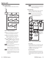
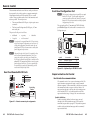
Quick Start Guide — FOX 500 Tx/Rx
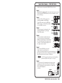
Install, connect, and operate the FOX 500 Tx/Rx as follows:
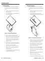
Step 1
Turn all of the equipment off or disconnect it from the power source.
If desired, mount the FOX 500 units in a rack or furniture, or place
them on desktops.
Step 2
Connect a VGA to UXGA source to the
transmitter: either to the RGB Input
15-pin HD connector or to the RGB Input
BNC connectors. See the drawing at right
to wire the BNC connectors.
R
G
H/HV
V
R
G
H/HV
V
R
G
H/HV
V
B
RGBHV
B
RGBS
Step 3
If desired, connect a local monitor to the
transmitter's Buffered Loop-Through
15-pin HD connector.
B
RGsB,
RsGsBs
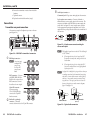
Step 4
Tip
Ring
Sleeve (s)
Tip
Ring
L
R
Balanced Stereo Input
Tip
Sleeve
L
Connect a balanced or unbalanced, stereo
or mono audio input to the transmitter:
either to the Audio Inputs 3.5 mm mini jack
or to the Audio Inputs 5-pole captive screw
connector. See the drawing at right to wire
the captive screw connector.
Step 5
R
Tip
Sleeve
Unbalanced Stereo Input
If you want the FOX 500 to pass serial
signals, such as for serial control of a
projector, connect the master device to the transmitter and
the slave device to the receiver via three poles of the RS-232
Over Fiber captive screw connector on both units.
RS-232
OVER FIBER
Tx Rx
NA
N For RS-232 responses (from the receiver to the transmitter),
you must install fiber cable Optical 2. See Step 8.
Step 6
For serial control of the transmitter and receiver, connect
a host device to either unit via three poles of the Remote
RS-232/Alarm captive screw connector or to either unit's
front panel Configuration
connector.
Controlling
Device
Transmit (Tx)
Receive (Rx)
Ground ( )
REMOTE
RS-232 ALARM
Tx Rx
1
2
Bidirectional
Transmit (Tx)
Receive (Rx)
Ground ( )
FOX 500 Tx/Rx • Quick Start Guide
QS-1
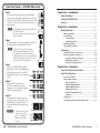
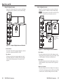
Quick Start Guide — FOX 500 Tx/Rx cont’d
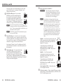
Step 7
REMOTE
RS-232 ALARM
For remote monitoring of the status of the optical links,
connect a locally constructed or obtained device to the two
Alarm poles of the units' RS-232/Alarm 5-pole captive screw
connectors. The two poles are shorted together when no
light is detected.
Tx Rx
2
Mounting the Unit..................................................................... 2-2
LINK
LINK
OPTICAL
1 2*
OPTIONAL FOR
* RETURN
DATA
Step 8
Connect the Optical 1 (required) and Optical 2 (optional)
fiber cables between the transmitter and receiver.
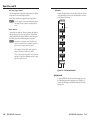
Step 9
Connect 1 or 2 RGBHV, RGBS, or RGsB
displays to the receiver: to the RGB Output
15-pin HD connector and/or to the RGB
Outputs BNC connectors. See the drawing
at right.
Using the menu system, select the
Alt. Pixels test pattern (see chapter 3,
"Operation"). Set your display's total pixel
and phase for the best picture.
Step 11
LINK
LINK
Chapter Three • Operation....................................................... 3-1
R
G
B
Front Panel Controls and Indicators..................................... 3-2
Front Panel Operations. ........................................................... 3-3
H
V
S
Power-on indications.............................................................. 3-3
Menu system overview.......................................................... 3-4
R
G
B
H
V
S
R
G
B
H
V
S
RGBHV
RGBS
Tip
NO GROUND.
NO GROUND.
R
FOX 500 Tx/Rx • Quick Start Guide
Picture Control menu..............................................................3-5
Output Configuration menu...................................................3-6
Audio Configuration menu.....................................................3-7
Memory Presets menu............................................................3-8
Advanced Configuration menu..............................................3-9
Exit menu...............................................................................3-11
System reset.......................................................................... 3-11
Front panel security lockout (executive mode).................. 3-12
Balanced Stereo Output
L
Connect the sleeve to ground
(Gnd). Connecting it to a
negative (-) terminal will
damage the audio output
circuits.
Tip
Ring
Sleeve(s)
Tip
Ring
Rear panel serial ports connection.......................................2-14
Alarm outputs connection....................................................2-15
Front panel Configuration ports..........................................2-15
R
QS-2
OPTICAL
2* 1
L
C
Transmitter rear panel connections....................................... 2-6
Receiver rear panel connections.......................................... 2-10
RGsB
Connect balanced or unbalanced stereo or
mono audio devices to the receiver: to the
Audio Outputs 3.5 mm mini jack and/or
to the Audio Outputs 5-pole captive screw
connector.
UL requirements......................................................................2-2
Mounting instructions............................................................2-3
Connections.................................................................................. 2-6
OPTIONAL FOR
* RETURN
DATA
Step 10
Tabletop placement................................................................ 2-2
Rack mounting........................................................................ 2-2
Furniture mounting................................................................ 2-4
Through-desk mounting........................................................ 2-5
N Only Optical 1 is required for video, audio,
and serial command transmission. Optical
2 is required only to send serial data (such as
commands from the receiver to the transmitter and
passed responses from the controlled device (such
as a projector) to the controlling device.
About this Manual..................................................................... 1-2
About the FOX 500 Tx/Rx........................................................ 1-2
Features......................................................................................... 1-4
Chapter Two • Installation....................................................... 2-1
N The transmitter's Alarm port reports the status of
the Optical 2 light link.
The receiver's Alarm port reports the status of the
Optical 1 light link.
1
Chapter One • Introduction..................................................... 1-1
Sleeve(s)
Tip
Unbalanced Stereo Output
FOX 500 Tx/Rx • Table of Contents
Table of Contents, cont'd
Chapter 4 • Remote Control. .................................................. 4-1
Rear Panel Remote RS-232 Ports........................................... 4-2
Front Panel Configuration Port. ............................................ 4-3
Simple Instruction Set Control............................................... 4-3
Host-to-interface communications........................................ 4-3
Symbol definitions..................................................................4-3
Unit-initiated messages. ........................................................ 4-4
Error responses....................................................................... 4-6
Timeout................................................................................... 4-6
Using the command/response table..................................... 4-6
Windows®-Based Program Control. ................................... 4-16
Installing the software........................................................ 4-16
Starting the program............................................................ 4-16
Status area.............................................................................4-18
Memory Preset area..............................................................4-18
Mute area...............................................................................4-19
Video Adjustment area.........................................................4-19
Output Configuration area...................................................4-20
Advanced Configuration area..............................................4-20
Audio Adjustment area.........................................................4-21
Audio Output Level area.......................................................4-22
Firmware upgrade................................................................ 4-23
Appendix A • Reference Information..............................A-1
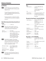
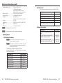
Specifications...............................................................................A-2
Part Numbers...............................................................................A-6
FOX 500 part numbers............................................................A-6
Included parts.........................................................................A-7
Optional accessories...............................................................A-7
Cables......................................................................................A-8
FOX 500 Tx/Rx
1
Chapter One
Introduction
About this Manual
About the FOX 500 Tx/Rx
Features
68-1308-01 Rev. A
01 07
All trademarks mentioned in this manual are the properties of their respective owners.
ii
FOX 500 Tx/Rx • Table of Contents
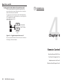
Introduction
The FOX 500 Tx/Rx units output continuous
invisible light, which may be harmful and
dangerous to the eyes; use with caution.
Local
Monitor
• Do not look into the rear panel fiber optic
PC
transceivers when the fiber optic cable is
unplugged.
0 Tx
X 50
FO
AL
TIC
OP 2*
1
NA
Tx
About this Manual
•
•
PU
B IN
RG
Extron
FOX 500 Tx
OP
DIO
AU L
1
Tx
Up to 30 km (18.75 miles)
singlemode fiber
SM Model
FOR
AL A
ION DAT
OPTURN
* RET
2
Rx
T
G
0.3
0V
-24 60 Hz
100 50/
T LO
TS
INPU R
M
AR
2 AL
-23 L
RS RO
NT
CO
A
B
B
RG
OR
V
H
Optional Second
Link for
Box to Box
Communcations
Fiber Optic Transmitter
FOX 500 MM Tx/Rx, a multimode (long distance up to 150 m [450']) transmitter/receiver pair
2
12
A
MP UTS
TP
OU ms
Oh
4/8
US
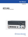
The transmitter inputs VGA - UXGA RGB video, audio, and
one-way (transmitter-to-receiver) RS-232 communications
(for applications such as projector control); converts them to a
proprietary signal; and outputs the signal on a single fiber optic
cable to the receiver. Optional return (receiver-to-transmitter)
serial RS-232 communications, such as projector responses,
require a second fiber optic cable. The transmitter also buffers
the RGB input and loops it through on a 15-pin HD connector
for use by a local monitor.
RE
0R
X 50
FO
AL
TIC
OP 1
2*
2
-23 ER
RS FIB
ER
OV
NA
UT
OU
DIO
AU
L
UT
TP
B OU
RG
L
R
R
1
Tx
M
AR
2
x
Audio
Output
FOR
AL A
ION DAT
OPTURN
* RET
Rx
R
L
Extron
MPA 122
Mini Power Amplifier
S
B
G
0.3
0V
-24 60 Hz
100 50/
Rx
TE AL
MO 2
RE -23
RS
TP
TE
MO
TE
10V /MU
VOL
R
N The two products are physically and functionally identical,
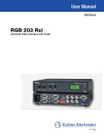
The Extron FOX 500 Tx/Rx (figure 1-1) are two models of
ultra-high performance RGB video, audio, and RS-232 serial
communications fiber optic transmitter/receiver pairs.
C
R
L
WE
PO
Tx
About the FOX 500 Tx/Rx
Two-way Ceiling
Speakers
S
UT
INP
FOX 500 SM Tx/Rx, a singlemode (very long distance up to 30 km [18.75 miles]) transmitter/receiver pair
with the exception of the effective range of transmission. In this manual, the term "FOX 500" refers to either
product.
Extron
SI 26X
Audio
R
LINK
This manual contains information about the following two
Extron FOX 500 Tx/Rx fiber optic transmitter and receiver set
products:
INPU
RU
TH
Rx
LINK
2
-23 RU
RS TH
S
PAS
LINK
• Plug the attached dust caps into the optical
RS-232
Projector
Control
RS-232
FOX 500
Control
cable connectors or into the fiber optic cables
themselves.
LINK
W
B
RG
A
Extron
FOX 500 Rx
Fiber Optic Receiver
R
V
H
RS-232
Display
Projector
Figure 1-1 — Typical FOX 500 Tx/Rx application
The receiver converts the proprietary signal(s) back to video,
audio, and serial RS-232 communication, and outputs it locally.
If RS-232 return communications are implemented (a second
fiber optic cable is installed), the receiver outputs a proprietary
serial communication signal to the transmitter on the second
fiber optic cable. For video resolutions up to 1600 x 1200, the
receiver's video output is a perfect, pixel-by-pixel recreation of
the video signal input to the transmitter.
The transmitter and receiver have image and audio adjustments.
Both units have image, audio, and fiber light status and lostlight alarm indicators. The transmitter can handle an RGBHV,
RGBS, RGsB, or RsGsBs input signal. The receiver can output
RGBHV, RGBS, or RGsB, as selected by the user.
The receiver has built-in alternating pixels, Color Bars, and
grayscale test patterns to assist in setting up the display
equipment.
1-2
FOX 500 Tx/Rx • Introduction
FOX 500 Tx/Rx • Introduction
1-3
Introduction, cont’d
The FOX 500 transmitter and receiver are both rack mountable
and have internal switching power supplies for worldwide
power compatibility.
Features
Ultra high performance — Offers perfect, pixel-by-pixel
RGBHV video transmission, up to 1600 x 1200 at 60 Hz.
Higher resolutions can be transmitted, but with some loss
of video quality.
Video input — The transmitter inputs RGBHV, RGBS, RGsB, or
RsGsBs on BNC connectors or a 15-pin HD connector.
Analog loop-through on transmitter — The transmitter has
an analog loop-through, on a 15-pin HD connector that
allows connection of a local monitor.
Video output — The receiver outputs RGBHV, RGBS, or RGsB
(user-selectable) on BNC connectors and a 15-pin HD
connector.
Audio input — Balanced or unbalanced stereo audio is input to
the transmitter on a 3.5 mm, 5-pole captive screw terminal
or a 3.5 mm mini jack.
Audio input gain/attenuation — The input audio level can be
adjusted within a range of (-18 dB attenuation to +10 dB
gain) via the front panel or the RS-232 link.
Upgradable firmware — The firmware that controls each unit's
operation can be upgraded in the field via an RS-232 link,
without taking the unit out of service. Firmware
upgrades are available for download on the Extron Web
site, www.extron.com, and they can be installed using the
Windows-based control program.
Memory presets — 30 memory presets are a time-saving feature
that lets you store input size and position settings relative
to a specific input resolution. You can then recall those
settings, when needed, with a few simple steps.
Rack mounting — Both units are rack mountable in any
conventional 19" wide rack, using Extron's full size rack
shelf.
Front panel security lockout (Executive mode) on receiver —
If a receiver is installed in an open area, where operation
by unauthorized personnel may be a problem, a security
lockout feature can be implemented. When the front
panel is locked, an SIS command is required to unlock the
unit before it can be operated from the front panel.
(The transmitter has no front panel controls.)
Power — Each unit's 100 VAC to 240 VAC, autoswitchable,
internal power supply provides worldwide power
compatibility.
Audio output — Balanced or unbalanced stereo audio is output
from the receiver on a 3.5 mm, 5-pole captive screw
terminal and a 3.5 mm mini jack.
Links monitoring — Both units' front panels have indicators
for monitoring image and audio transmission and both
fiber optic links.
Loss-of-light alarms — Both units' rear panels have discrete
outputs that indicate if either of the fiber optic links
have suffered a loss of the light signal.
Windows-based control program — For RS-232 remote
control from a PC, the Extron Windows-based control
software provides a graphical interface and drag-anddrop/point-and-click operation.
Simple Instruction Set (SIS™) — The transmitter and
receiver both use Extron’s SIS for easy remote control
operation.
Audio level — The audio output can be set to either the
consumer level (-10 dBV) or professional level (+4 dBu)
from the front panel or under RS-232 control.
1-4
FOX 500 Tx/Rx • Introduction
FOX 500 Tx/Rx • Introduction
1-5
Introduction, cont’d
FOX 500 Tx/Rx
2
Chapter Two
Installation
Mounting the Unit
Connections
1-6
FOX 500 Tx/Rx • Introduction
Installation
Mounting the Unit
C Installation and service must be performed by
authorized personnel only.
Either 1U high, half-rack width unit can be placed on a tabletop,
mounted on a rack shelf, or mounted under or through a desk or
other furniture.
Tabletop placement
Affix the four included rubber feet to the bottom of the unit and
place it in any convenient location.
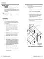
Rack mounting
UL requirements
The following Underwriters Laboratories (UL) requirements
pertain to the installation of the FOX 500 transmitter or receiver
into a rack (figure 2-1).
1.
2.
2-2
•
•
Reduced air flow — Installation of the equipment in a rack
should be such that the amount of air flow required for
safe operation of the equipment is not compromised.
Mechanical loading — Mounting of the equipment in
the rack should be such that a hazardous condition is not
achieved due to uneven mechanical loading.
4.
Circuit overloading — Consideration should be given to
the connection of the equipment to the supply circuit and
the effect that overloading of the circuits might have on
overcurrent protection and supply wiring. Appropriate
consideration of equipment nameplate ratings should be
used when addressing this concern.
Reliable earthing (grounding) — Reliable earthing
of rack-mounted equipment should be maintained.
Particular attention should be given to supply connections
other than direct connections to the branch circuit (such as
the use of power strips).
FOX 500 Tx/Rx • Installation
RSU 129 9" 1U universal rack shelf kit (part #60-190-01)
(figure 2-1)
RSB 129 9" 1U basic rack shelf (part #60-604-01)
1.
If installed, remove the feet from the bottom of the unit.
2.
Mount the unit on either the left or right side of the shelf,
using two 4-40 x 3/16" screws in opposite (diagonal)
corners to secure the unit to the shelf.
3.
Install a false faceplate or another to the rack shelf.
4.
Insert the shelf into the rack, aligning the holes in the shelf
with those of the rack.
5.
Secure the shelf to the rack using the supplied machine
screws.
1U Universal Rack Shelf
Elevated operating ambient — If installed in a closed
or multi-unit rack assembly, the operating ambient
temperature of the rack environment may be greater
than room ambient. Therefore, consider installing the
equipment in an environment compatible with the
maximum ambient temperature (Tma) specified by the
manufacturer.
3.
5.
Mounting instructions
For optional rack mounting, mount either unit on either of the
following rack shelves:
1/2 Rack Width Front False
Faceplate
Front false
faceplate
uses 2
screws.
(2) 4-40 x 3/16"
Screws
NOTE: Using screws longer
Use 2 mounting holes on
opposite corners.
than 3/16” will damage the
unit and void the warranty.
Figure 2-1 — Mounting the unit on a standard rack shelf
FOX 500 Tx/Rx • Installation
2-3
Installation, cont’d
Furniture mounting
Mount either unit under a desk or podium using the optional
Extron MBU 125 under desk mounting kit (part #70-077-01) as
follows:
Through-desk mounting
Mount the unit through a desk or podium using the optional
Extron MBD 129 through desk mounting kit (part #70-077-02) as
follows:
1.
If rubber feet were previously installed on the bottom of
the unit, remove them.
1.
If rubber feet were previously installed on the bottom of
the unit, remove them.
2.
Affix the mounting brackets to the unit with the machine
screws provided (figure 2-2).
2.
Secure the brackets to the unit with the provided
machine screws (figure 2-3). Leave the screws slightly loose.
Figure 2-2 — Under-desk mounting the unit
Hold the unit with the brackets attached against the
underside of the table or other furniture. Mark the location
of the screw holes of the bracket on the mounting surface.
4.
Drill four pilot holes, each 3/32" (2 mm) in diameter by
1/4" deep (6.3 mm) deep in the mounting surface at the
marked screw locations.
3.
5.
Insert #8 wood screws into the four pilot holes. Tighten
each screw into the mounting surface until just less than
1/4" (6.3 mm) of the screw head protrudes.
Hold the unit and brackets on the underside of the surface
to which you are mounting the device and mark the four
screw holes and the table material to be removed.
4.
6.
Align the mounting screws with the slots in the brackets
and place the unit against the surface, with the screws
through the bracket slots.
Remove the table material. Test the fit by inserting the
front of the device through the hole. If necessary, use a
rasp or coarse file to enlarge the hole.
5.
Drill four pilot holes, each 3/32" (2 mm) in diameter by
1/4" deep (6.3 mm) deep , as marked on the template.
7.
Slide the unit slightly in or out, then tighten all four screws
to secure the unit in place (figure 2-2).
6.
Using the four wood screws provided, attach the brackets
to the mounting surface.
7.
Slide the device in or out until it is in the desired position.
Tighten the screws installed in step 2.
If the screws are inaccessible to a screwdriver:
3.
Figure 2-3 — Through-desk mounting the unit
a. Mark the location of the brackets relative to the screws.
2-4
FOX 500 Tx/Rx • Installation
FOX 500 Tx/Rx • Installation
2-5
Installation, cont’d
b. Remove the transmitter or receiver from inside the
furniture.
c
c. Tighten the screws.
d. Replace the unit inside the surface (step 6).
Connections
Transmitter rear panel connections
All connectors except the Configuration port are on the rear
panel (figure 2-4).
RS-232
OVER FIBER
Tx Rx
R
G
B
L
V
REMOTE
RS-232 ALARM
R
RGB
Tx Rx
8
5
1
Do not tin the wires!
OPTICAL
1 2*
NA
AUDIO INPUTS
OR
H/HV
FOX 500 Tx
LINK
INPUT LOOP THRU
Tip
Sleeve
4
LINK
RGB INPUT
3
6 7
to only the BNC
connectors or
the 15-pin HD
connector, not
both.
b
2-6
BNC connectors — Connect
an RGBHV, RGBS, RGsB, or
RsGsBs video source to these
BNC connectors. Connect
the cables as shown at right.
15-pin HD connector —
Connect an analog
VGA - UXGA RGB video
source to this 15-pin HD
female connector.
Unbalanced Stereo Input
Balanced Stereo Input
• If the stripped section of wire is longer than 3/16”,
the exposed wires may touch, causing a short circuit
between them.
RGBHV
R
G
H/HV
V
• If the stripped section of wire is shorter than 3/16”,
B
wires can be easily pulled out even if tightly fastened
by the captive screws.
N See figure 2-6 to identify the tip, ring, and sleeve when you
are making connections for the transmitter from existing
audio cables. A mono audio connector consists of the tip
and sleeve. A stereo audio connector consists of the tip,
ring and sleeve. The ring, tip, and sleeve wires are also
shown on the captive screw audio connector diagrams,
figure 2-5 and figure 2-8.
RGBS
RGsB,
RsGsBs
R
G
H/HV
V
B
Tip (+)
R
Buffered Loop-through
H/HV
connector — If desired,
connect a local monitor to this 15-pin HD connector.
FOX 500 Tx/Rx • Installation
Tip
Sleeve
N The length of exposed wires is critical. The ideal length
is 3/16” (5 mm).
RGB Input connectors —
N Connect an input
Tip
Ring
Sleeve (s)
Tip
Ring
Figure 2-5 — Captive screw connector wiring for
stereo audio input
OPTIONAL FOR
* RETURN
DATA
2
Figure 2-4 — FOX 500 Tx transmitter’s connectors
a
5-pole captive screw connector — Connect a balanced or
unbalanced stereo or mono audio input to this connector. The
connector is included with FOX 500, but you must supply the
audio cable. See figure 2-5 to wire a captive screw connector
for the appropriate input type and impedance level. Use the
supplied tie-wrap to strap the audio cable to the extended tail of
the connector.
R
2
3.5 mm mini jack —Plug a stereo mini plug into this connector.
L
100-240V 0.3A
50/60 Hz
1
Audio Input connectors —
G
B
Sleeve ( )
V
Tip (+)
Ring (-)
RCA Connector
Sleeve ( )
3.5 mm Stereo Plug Connector
(balanced)
Figure 2-6 — Typical audio connectors
FOX 500 Tx/Rx • Installation
2-7
Installation, cont’d
RS-232 Over Fiber port — If you want the
FOX 500 to pass serial command signals to
the receiver, for serial control of a projector
for example, connect the host device to the
transmitter via three poles of this 5-pole captive
screw connector. See "Rear panel serial ports
connections" on page 2-14 to wire this connector.
W
RS-232
OVER FIBER
Tx Rx
NA
1
transmitter/receiver pair. Typically, singlemode fiber has a
yellow jacket and multimode cable has an orange jacket.
2
N Only one fiber optic cable, Optical 1, is required for video,
N If you connect only one fiber optic cable (item g, on the
next page), you will not receive reports from the controlled
device. To receive responses from the controlled device, you
must install two fiber optic cables.
audio, and serial command transmission. But, if you
connect only one fiber optic cable, you will not receive
RS-232 reports from the controlled device, and there will
be reduced front panel, Windows-based control program,
and RS-232 command functionality on the RX unit. To
receive responses from the controlled device and for full
functionality, you will need to install both fiber optic
cables.
N The FOX 500 can pass RS-232 commands and responses
at rates up to 38400 baud.
Remote RS-232 port — For serial control of the transmitter,
connect a host device, such as a computer, touch panel control,
or RS-232 capable PDA, to the transmitter via three poles of this
5-pole captive screw connector. See "Rear panel serial ports
See chapter 4, "Remote Control", for definitions of the SIS
commands (serial commands to control the transmitter via
this connector).
Optical 1 — For all one-way video, audio, and
serial communications from the transmitter to
the receiver, connect a fiber optic cable to the
Optical 1 LC connector.
Connect the free end of this fiber optic
cable to the Optical 1 connector on the
FOX 500 Rx receiver (item n in "Receiver rear
panel connections").
Optical 2 — For all one-way serial
communications from the receiver to the
transmitter, connect a fiber optic cable to the
Optical 2 LC connector.
Connect the free end of this fiber optic
cable to the Optical 2 connector on the
FOX 500 Rx receiver (item n in "Receiver rear
panel connections").
Link 1 and Link 2 LEDs — When lit, the link
is active (light is received).
h
AC power connector — Plug a standard IEC power cord into
this connector to connect the transmitter to a 100 VAC to 240
VAC, 50 or 60 Hz power source.
f
2-8
REMOTE
Alarm outputs port — For remote monitoring
RS-232 ALARM
of the status of fiber optic link 2, connect a
locally-constructed or furnished device to the
Tx Rx
1 2
transmitter via two poles of this 5-pole captive
screw connector. When the transmitter does not detect a
light link on fiber cable Optical 2 (optional), pin 1 and pin 2
of this port are shorted together.
FOX 500 Tx/Rx • Installation
LINK
connections" on page 2-14 to wire this connector.
OPTICAL
1 2*
OPTIONAL FOR
* RETURN
DATA
OPTICAL
2* 1
LINK
e
These units output continuous invisible light,
which may be harmful and dangerous to the eyes;
use with caution. For additional safety, plug the
attached dust caps into the optical transceivers
when the fiber optic cable is unplugged.
N Ensure that you use the proper fiber cable for your
REMOTE
RS-232 ALARM
Tx Rx
Fiber optic connectors and LEDs —
LINK
d
g
The input's audio level can be individually set via the front
panel or RS-232 control. See chapter 3, "Operation", and
chapter 4, "Remote Control".
LINK
OPTIONAL FOR
* RETURN
DATA
FOX 500 Tx/Rx • Installation
2-9
Installation, cont’d
Receiver rear panel connections
j
All connectors except the Configuration port are on the rear
panel (figure 2-7).
11
RS-232
OVER FIBER
RGB OUTPUTS
Tx Rx
R
G
B
V
S
OPTICAL
2* 1
NA
AUDIO OUTPUTS
L
H
FOX 500 Rx
REMOTE
RS-232 ALARM
R
RGB
Tx Rx
15
12
1
LINK
10
LINK
9
100-240V 0.3A
50/60 Hz
OPTIONAL FOR
* RETURN
DATA
2
13 14
Audio Outputs connectors —
3.5 mm mini jack —Plug a stereo mini plug into this connector.
5-pole captive screw connector — This 5-pole, 3.5 mm captive
screw connector outputs the transmitted unamplified,
line level audio. Connect audio devices, such as an audio
amplifier or powered speakers.
See figure 2-8 to properly wire a captive screw output connector.
Use the supplied tie-wrap to strap the audio cable to the
extended tail of the connector.
Do not tin the wires!
RGB Outputs connectors —
BNC connectors — Connect
an RGBHV, RGBS, RGsB,
or RsGsBs video display
to these BNC connectors.
Connect the cables as shown
at right.
15-pin HD connector —
Connect an analog
VGA - UXGA RGB video
display to this 15-pin HD
female connector.
N You can set the
FOX 500 Tx/Rx • Installation
NO GROUND HERE.
Unbalanced Stereo Output
R
G
B
C
H
V
S
G
Connect the sleeve to ground (Gnd). Connecting
the sleeve to a negative (-) terminal will damage the
audio output circuits.
N The length of exposed wires is critical. The ideal length
is 3/16” (5 mm).
RGBS
R
Balanced Stereo Output
Figure 2-8 — Captive screw connector wiring for
stereo audio output
RGBHV
B
• If the stripped section of wire is longer than 3/16”,
H
V
receiver to output
the desired video
RGsB
format, RGBHV,
R
G
RGBS, or RGsB. RGBHV is the
default. See
V
H
"Format submenu"
in "Output
Configuration menu" in chapter 3, "Operation".
2-10
Sleeve(s)
Tip
R
NO GROUND HERE.
L
i
Tip
Ring
Sleeve(s)
Tip
Ring
Tip
Figure 2-7 — FOX 500 Rx receiver’s connectors
the exposed wires may touch, causing a short circuit
between them.
S
• If the stripped section of wire is shorter than 3/16”,
wires can be easily pulled out even if tightly fastened
by the captive screws.
B
S
The volume level for the output can be set to either the
consumer level (-10 dBV) or the professional level (-4 dBu) via
the front panel or Ethernet or RS-232 control. See chapter 3,
"Operation", and chapter 4, "Remote Control", for details.
FOX 500 Tx/Rx • Installation
2-11
Installation, cont’d
W
NA
REMOTE
RS-232 ALARM
Tx Rx
1
2
transmitter/receiver pair. Typically, singlemode fiber has a
yellow jacket and multimode cable has an orange jacket.
you will not receive reports from the controlled device. To
receive responses from the controlled device, you will need
to install two fiber optic cables.
N Only one fiber optic cable, Optical 1, is required for video,
audio, and serial command transmission. But, if you
connect only one fiber optic cable, you will not receive
RS-232 reports from the controlled device, and there will
be reduced front panel, Windows-based control program,
and RS-232 command functionality on the RX unit. To
receive responses from the controlled device and for full
functionality, you will need to install both fiber optic
cables.
N The FOX 500 can pass RS-232 commands and responses
at rates up to 38400 baud.
Remote RS-232 port — For serial control of the receiver,
connect a host device, such as a computer, touch panel control,
or RS-232 capable PDA, to the transmitter via three poles of this
5-pole captive screw connector. See "Rear panel serial ports
connections" on page 2-14 to wire this connector.
m
2-12
See chapter 4, Remote Control, for definitions of the SIS
commands (serial commands to control the transmitter via this
connector).
Alarm outputs port — For remote monitoring of REMOTE
RS-232 ALARM
the status of fiber optic link 1, connect a locallyconstructed or furnished device to the receiver
Tx Rx
1 2
via two poles of this 5-pole captive screw
connector. When the receiver does not detect a
light link on fiber cable Optical 1, pin 1 and pin 2 of this port
are shorted together.
FOX 500 Tx/Rx • Installation
These units output continuous invisible light,
which may be harmful and dangerous to the eyes;
use with caution. For additional safety, plug the
attached dust caps into the optical transceivers
when the fiber optic cable is unplugged.
N Ensure that you use the proper fiber cable for your
N If you connect only one fiber optic cable (item n, below),
l
Fiber optic connectors and LEDs —
OPTICAL
2* 1
Optical 1 — For all one-way video, audio, and
serial communications from the transmitter to
the receiver, connect a fiber optic cable to the
Optical 1 LC connector.
Connect the free end of this fiber optic cable
to the Optical 1 connector on the FOX 500 Tx
transmitter (item g in "Transmitter rear panel
connections").
Optical 2 — For all one-way serial
communications from the receiver to the
transmitter, connect a fiber optic cable to the
Optical 2 LC connector.
Connect the free end of this fiber optic cable
to the Optical 2 connector on the FOX 500 Tx
transmitter (item g in "Transmitter rear panel
connections").
Link 1 and Link 2 LEDs — When lit, the link
is active (light is received).
o
AC power connector — Plug a standard IEC power cord
into this connector to connect the receiver to a 100 VAC to
240 VAC, 50 or 60 Hz power source.
LINK
Tx Rx
n
OPTIONAL FOR
* RETURN
DATA
OPTICAL
1 2*
LINK
RS-232
OVER FIBER
LINK
RS-232 Over Fiber port — If you want the
FOX 500 to pass serial command signals to
the receiver, for serial control of a projector
for example, connect the host device to the
transmitter via three poles of this 5-pole captive
screw connector. See "Rear panel serial ports
connections" on page 2-14 to wire this connector.
LINK
k
OPTIONAL FOR
* RETURN
DATA
FOX 500 Tx/Rx • Installation
2-13
Installation, cont’d
Rear panel serial ports connection
Alarm outputs connection
RS-232
OVER FIBER
Tx Rx
REMOTE
RS-232 ALARM
Tx Rx
NA
Pin
TX
RX
Gnd
REMOTE
RS-232 ALARM
Tx Rx
1
1
Pin 1 and pin 2 are
shorted together when
no light is detected.
2
Function
Transmit data
Receive data
Signal ground
2
Do not tin the wires!
Do not tin the wires!
Ground ( )
Receive (Rx)
Transmit (Tx)
Bidirectional
Figure 2-10 — Alarms connector
Controlling
Device
N The length of exposed wires is critical. The ideal length is
3/16" (5 mm).
Ground ( )
Receive (Rx)
Transmit (Tx)
• If the stripped section of wire is longer than 3/16",
the exposed wires may touch, causing a short circuit
between them.
NOTE For the RS-232 Over Fiber port, only cross the Tx and
Rx lines once between the source and the target.
• If the stripped section of wire is shorter than 3/16",
Figure 2-9 — RS-232 connectors
wires can be easily pulled out even if tightly fastened
by the captive screws.
N The RS-232 Over Fiber port is for transmission of serial
signals, such as projector control signals, between the
transmitter and receiver.
The Remote RS-232 port is for remote control of the
transmitter and receiver.
Front panel Configuration ports
N The length of exposed wires is critical. The ideal length is
3/16" (5 mm).
RGB
LINK 1
AUDIO
LINK 2 (OPTIONAL)
16
the exposed wires may touch, causing a short circuit
between them.
MENU
If the stripped section of wire is shorter than 3/16",
wires can be easily pulled out even if tightly fastened
by the captive screws.
2-14
FOX 500 Tx/Rx • Installation
ADJUST
NEXT
RGB
LINK 1
AUDIO
LINK 2 (OPTIONAL)
CONFIG
FOX 500 Rx
HIGH RESOLUTION FIBER OPTIC RECEIVER
N The rear panel Remote RS-232 port is active only if the
front panel Configuration port is not in use. If a front
panel configuration connection is made, the Remote
RS-232 port becomes inactive and the front panel
Configuration port is active.
FOX 500 Tx
HIGH RESOLUTION FIBER OPTIC RECEIVER
• If the stripped section of wire is longer than 3/16",
•
CONFIG
Figure 2-11 — FOX 500 Tx/Rx front panels
N These ports are for remote control of the transmitter or
receiver, not for the over fiber RS-232 link.
p
Configuration port — These 2.5 mm mini stereo jacks serve
the same serial communications function as the rear panel
Remote RS-232 ports, but are easier to access than the rear
ports after the units have been installed and cabled. The
optional 9-pin D to 2.5 mm mini jack TRS RS‑232 cable,
part #70-335-01 (figure 2-12), can be used for this connection.
FOX 500 Tx/Rx • Installation
2-15
Installation, cont’d
FOX 500 Tx/Rx
6 feet
(1.8 m)
1
Part #70-335-01
6
9
5
Tip
Ring
Sleeve (Gnd)
9-pin D
Connection
TRS Plug
Pin 2
Pin 3
Pin 5
Computer's RX line
Computer's TX line
Computer's signal ground
Tip
Ring
Sleeve
Figure 2-12 — Optional 9-pin TRS RS-232 cable
N These ports parallel the rear panel Remote RS-232 ports. If a front panel configuration connection is made, the rear
panel Remote RS-232 port becomes inactive and the front
panel Configuration port is active.
This port is RS-232 only, with the following protocols:
• 9600 baud
• 1 stop bit
• no parity
• no flow control
• 8 data bits
N The maximum distances from the transmitter or receiver
to the controlling device can vary up to 200 feet (61 m). Factors such as cable gauge, baud rates, environment, and
output levels (from the unit and the controlling device) all
affect transmission distance. Distances of about 50 feet
(15 m) are typically not a problem. In some cases, the unit
may be capable of serial communications via RS‑232 up to
250 feet (76 m) away.
2-16
FOX 500 Tx/Rx • Installation
3
Chapter Three
Operation
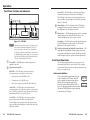
Front Panel Controls and Indicators
Front Panel Operations
Operation
Front Panel Controls and Indicators
RGB
LINK 1
AUDIO
LINK 2 (OPTIONAL)
CONFIG
FOX 500 Tx
HIGH RESOLUTION FIBER OPTIC TRANSMITTER
1
2
3
4
5
MENU
ADJUST
NEXT
RGB
LINK 1
AUDIO
LINK 2 (OPTIONAL)
CONFIG
Status display — The 12-column by 2-line LCD displays
configuration menus and status information. See "Front
Panel Operations" in this chapter for details.
d
Menu button — The Menu button enters and moves through
the main menu system in the FOX 500 Rx receiver. See
"Front Panel Operations" in this chapter for details.
FOX 500 Rx
N Only one fiber optic cable, Optical 1, is required for video,
audio, and serial command transmission. But, if you
connect only one fiber optic cable, you will not receive
RS-232 reports from the controlled device, and there will
be reduced front panel functionality. To receive responses
from the controlled device and for full functionality, you
will need to install both fiber optic cables.
a
Power LED — This LED lights to indicate the power is
applied to the unit.
b
Signal monitoring LEDs —
3-2
RGB LEDs — This LED lights on both units when the
transmitter detects a sync signal on its video input:
•
Horizontal sync (H) (for RGBHV video)
•
Composite sync (S) (for RGBS video)
•
Green (Sync on green) (G) (for RGsB or RsGsBs video)
Audio LEDs — This LED lights on both units when the
transmitter detects a low level audio signal for a short period of
time. This LED goes dark if the audio signal drops below the
minimum threshold for a short period of time.
This LED lights on the receiver when the transmitter detects
light on the fiber optic cable Optical 2 and the fiber optic cable
Optical 1 is installed.
c
HIGH RESOLUTION FIBER OPTIC RECEIVER
Figure 3-1 — FOX 500
Link 2 LEDs — This LED lights on the transmitter when the
transmitter detects light on the fiber optic cable Optical 2.
e
Next button — The Next button steps through the submenus
in the FOX 500 receiver menu system. See "Front Panel
Operations" in this chapter for details.
Adjust [ (horizontal) and Adjust { (vertical) knobs — The
Adjust [ and Adjust { knobs change settings when used
in conjunction with the menu system. Rotate these knobs to
scroll through the selection options and make adjustments.
Front Panel Operations
The following paragraphs detail the power-up process and
then describe input selection, preset selection, Auto-Imaging,
and then details the menu system, the picture adjustments, and
selection of executive mode.
Power-on indications
Power is automatically applied when the power
cord is connected to an AC source. When AC
power is applied, both units perform self-tests.
When the self-test completes satisfactorily,
both units' signal monitoring LEDs (item b on
figure 3-1) light as appropriate for the connections.
The receiver's LCD displays the input vertical and
horizontal rates (or No Input).
FOX 500 MM
nn.nk nnHz
- or FOX 500 SM
nn.nk nnHz
Link 1 LEDs — This LED lights on the receiver when the
receiver detects light on the fiber optic cable Optical 1.
This LED lights on the transmitter when the receiver detects
light on the fiber optic cable Optical 1 and the fiber optic cable
Optical 2 is installed.
FOX 500 Tx/Rx • Operation
FOX 500 Tx/Rx • Operation
3-3
Operation, cont’d
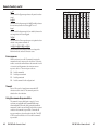
Menu system overview
N From any menu or submenu, after 30 seconds of inactivity,
Figure 3-2 shows a flowchart of the main menus in the menu
system.
the receiver saves all adjustment settings and times out to
the default (FOX 500) LCD display.
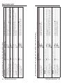
Picture Control menu
Figure 3-3 is a flowchart that shows an overview of the Picture
Control menu, its submenus, and the available settings.
Power
on
FOX 500
nn.nk nnHz
Menu
PICTURE
CONTROL
30 sec.
Menu
OUTPUT
CONFIG
30 sec.
Menu
N The Horizontal Start and Total Pixels/Pixel Phase
submenus are only available when both fiber cables are
installed between the transmitter and receiver.
FOX 500
nn.nk nnHz
Menu
AUDIO
CONFIG
30 sec.
Menu
MEMORY
PRESETS
30 sec.
Menu
Menu
PICTURE
CONTROL
30 sec.
30 sec.
30 sec.
Next
H POS V Next
HORZ START* Next
128
0000
Menu 128
Menu
Menu
30 sec.
Menu
ADVANCED
CONFIG
Menu
30 sec.
EXIT MENU
PRESS NEXT
Menu
Next
OUTPUT
CONFIG
Menu
AUDIO
CONFIG
000 to
255
000 to
255
0000 to
xxxx
Menu
Figure 3-2 — Menu system flowchart
Menu button — Press the Menu button to activate the menu
system and to scroll through the five main menus.
Next button — Press the Next button to move between the
submenus of a selected main menu, to activate one for
viewing or configuration, and to save a selection.
Adjust [ and Adjust { knobs — When in a submenu, rotate
the Adjust [ knob and Adjust { knob to scroll through
the submenu options and select a setting. Refer to the
flowcharts in this chapter and to specific sections for
explanations on knob adjustments.
N If you press the Menu button while a main menu is active,
the next main menu becomes active.
If you press the Menu button while a submenu is active,
the LCD backs up to display that submenu’s main menu.
N To return to the default screens, let the receiver remain idle
for 30 seconds until the selected screen times out, or press
the Menu button until the Exit Menu appears, then press
the Next button.
3-4
FOX 500 Tx/Rx • Operation
MEMORY
PRESETS
Menu
Tt Pix Phase * Next
000
Menu 0000
ADVANCED
CONFIG
Menu
EXIT MENU
PRESS NEXT
0000 to
xxxx
* This submenu is only
available when both fiber
cables are installed
between the transmitter
and receiver.
000 to
xxxx
Menu
Figure 3-3 — Picture Control menu flowchart
Position submenu
The position submenu allows you to shift the receiver's output
image horizontally and vertically on the display. Rotate the
Adjust [ knob to shift the image horizontally. Rotate the
Adjust { knob to shift the image vertically.
Horizontal Start submenu
The Horizontal Start submenu defines the horizontal position
of the first active pixel in the active area or the receiver's output.
Rotate either Adjust knob while in this submenu to set the start
variable.
FOX 500 Tx/Rx • Operation
3-5
Operation, cont’d
Output Configuration menu
Figure 3-4 is a flowchart that shows an overview of the Output
Configuration menu, its submenus, and the available settings.
FOX 500
nn.nk nnHz
N The Gain submenu is only available when both fiber cables
are installed between the transmitter and receiver.
Menu
FOX 500
nn.nk nnHz
30 sec.
PICTURE
CONTROL
Menu
Menu
OUTPUT
CONFIG
Menu
Audio Configuration menu
Figure 3-5 is a flowchart that shows an overview of the Audio
Configuration menu, its submenus, and the available settings.
Next
Menu
FORMAT
RGBHV
30 sec.
30 sec.
Next
Next
SYNC
Menu FLW FORCE
<
>
30 sec.
Menu
GAIN
00.0 dB
30 sec.
* Next
Next
MUTE
ON
Menu < OFF >
Menu
OUTPUT
CONFIG
AUDIO
CONFIG
Menu
Menu
MEMORY
PRESETS
30 sec.
PICTURE
CONTROL
• RGBHV
• RGsB
Menu
ADVANCED
CONFIG
Menu
EXIT MENU
PRESS NEXT
Menu
Figure 3-4 — Output Configuration menu flowchart
Format submenu
Rotate either Adjust while in the Format submenu to select the
desired video output format (RGBHV or RGsB).
Sync submenu
The display or projector may require a negative sync signal.
Rotate either Adjust knob to select FLW (Follow) (the output
video sync follows the input sync) or Force (sync is forced
negative).
AUDIO
CONFIG
-18.0 dB to
+10.0 dB
Next
Menu
MEMORY
PRESETS
Menu
ADVANCED
CONFIG
Menu
OUTPUT LVL Next * This submenu is only
available when both fiber
PRO
< CONS>
cables are installed
between the transmitter
and receiver.
Menu
EXIT MENU
PRESS NEXT
Menu
Figure 3-5 — Audio Configuration menu flowchart
Gain submenu
Rotate either Adjust knob while in the Gain submenu to select
the input audio gain or attenuation value, from -18 dB to +10 dB
in 1.0 dB increments. The default is a 0 dB audio level.
Mute submenu
Rotate either Adjust knob while in the Mute submenu while in
the Mute submenu to select or deselect the audio output mute
function.
Output Level submenu
Rotate either Adjust knob while in the Output Level submenu to
set the audio level for the output. The available levels are CONS
(consumer) level (–10 dBV) and PRO (professional) (+4 dBu).
3-6
FOX 500 Tx/Rx • Operation
FOX 500 Tx/Rx • Operation
3-7
Operation, cont’d
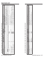
Memory Presets menu
Figure 3-6 is a flowchart that shows an overview of the Memory
Presets menu, its submenus, and the available settings.
FOX 500
nn.nk nnHz
Menu
30 sec.
30 sec.
30 sec.
Next
RECALL
29
Menu < NA >
Menu
PICTURE
CONTROL
Next
SAVE
< NA > 30
Menu
OUTPUT
CONFIG
Select N/A Preset
or a preset number:
number.
01 to 30.
AUDIO
CONFIG
Select N/A Preset
or a preset number:
number.
01 to 30.
Next
Menu
CLR PRESETS Next
< NO > YES
ADVANCED
CONFIG
Menu
EXIT MENU
PRESS NEXT
Menu
Figure 3-6 — Memory Presets menu flowchart
Memory presets, which are saved values of the horizontal and
vertical position and sizing information are saved in nonvolatile
memory. When the FOX 500 is powered down and later
powered back up, the settings are available for selection using
the Save submenu (see below). Saving the settings to a preset
overwrites the settings previously written to that preset.
Recall submenu
Rotate the Adjust [ knob while in the Recall submenu to select
(< >) either the displayed preset number (01 through 30) or N/A
(NA) for no preset. Press the Next button to recall the current
settings to the displayed preset. Select N/A and press the Next
button to exit the submenu without recalling the settings.
Save submenu
Rotate the Adjust [ knob while in the Save submenu to select
(< >) either the displayed preset number (01 through 30) or N/A
(NA) for no preset. Press the Next button to save the current
settings. Select N/A and press the Next button to exit the
submenu without saving the settings.
3-8
FOX 500
nn.nk nnHz
30 sec.
30 sec.
30 sec.
AUTO MEMORY Next
AUTO IMAGE Next
ON
Menu < OFF >
Menu TRIGGER
PICTURE
CONTROL
Menu
Menu
Menu
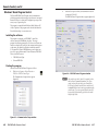
Advanced Configuration menu
Figure 3-7 is a flowchart that shows an overview of the
Advanced Configuration menu, its submenus, and the available
settings.
Menu
Menu
MEMORY
PRESETS
Clear Presets submenu
Rotate either Adjust knob to select (< >) Yes and press the Next
button to erase all presets. Select No and press Next to exit the
submenu without clearing the presets.
FOX 500 Tx/Rx • Operation
OUTPUT
CONFIG
Menu
AUDIO
CONFIG
Menu
PATTERN
NONE
Menu
MEMORY
PRESETS
Next
Menu
ADVANCED
CONFIG
Menu
EXIT MENU
PRESS NEXT
Next
•
•
•
•
None
Color Bars
Grayscale
Alt. Pixels
Menu
Figure 3-7 — Advanced Configuration menu
flowchart
Auto Memory submenu
The auto memory function automatically saves the horizontal
and vertical position, horizontal start, total pixels, and pixel
phase settings for different input resolutions. When on,
auto memory applies the settings based on the sensed input
resolution.
Rotate either Adjust knob while in the Auto Memory submenu
to select (< >) either on or off for the auto image function. Press
the Next button to save the current settings.
FOX 500 Tx/Rx • Operation
3-9
Operation, cont’d
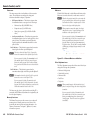
Auto Image Trigger submenu
The auto image function adjusts the output settings for the best
image, based on the sensed input resolution.
Rotate either adjust knob to trigger the auto image function.
N If no video input is connected, the submenu display reads
Auto Image N/A and no function is available from this
screen.
Pattern submenu
The receiver can output any of three test patterns that help you
adjust the display's color, focus, and grayscale. Rotate either
Adjust knob while in the Pattern submenu to select among the
Color Bars, grayscale, and alternating pixels test patterns.
N You must have a video input connected and fiber cable
Optical 1 connected between the transmitter and receiver
for the receiver to output a selected test pattern.
The test pattern will turn off if the input signal rate is
changed or disconnected or if power is removed.
The size of the test pattern depends on the size of the active
input signal. Any picture adjustments made on the input
affect the test patterns as well.
Exit menu
From the Exit menu (figure 3-8), press the Next button to return
to the default display cycle, or press the Menu button to return
to the Picture Control menu.
FOX 500
nn.nk nnHz
Menu
30 sec.
PICTURE
CONTROL
Menu
OUTPUT
CONFIG
Menu
AUDIO
CONFIG
Menu
MEMORY
PRESETS
Menu
ADVANCED
CONFIG
Menu
EXIT MENU
PRESS NEXT
Menu
Next
Figure 3-8 — Exit menu flowchart
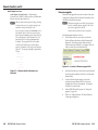
System reset
To reset the FOX 500 to the factory default settings, press and
hold the Menu button while applying power. After about 3
seconds, the LCD displays System Reset message. Release the
Menu button.
3-10
FOX 500 Tx/Rx • Operation
FOX 500 Tx/Rx • Operation
3-11
Operation, cont’d
Front panel security lockout (executive mode)
The front panel security lockout limits the operation of the
receiver from the front panel. When the receiver is locked, the
Menu and Next buttons are disabled.
To toggle the lock on and off, press and hold the Menu button
and the Next button for approximately two seconds (figure 3-9).
Press and hold the Menu and Next
buttons simultaneously to toggle the
front panel lock on or off.
Exe Mode
Enabled
MENU
2 seconds
NEXT
Exe Mode
Disabled
The LCD indicates
the front panel lock
(enabled or disabled).
Release the
Menu and Next
buttons.
Figure 3-9 — Toggle front panel lock on or off
If the user pushes either button when the receiver is locked, the
LCD displays Exe Mode Enabled.
FOX 500 Tx/Rx
4
Chapter 4
Remote Control
Rear Panel Remote RS-232 Ports
Front Panel Configuration Port
Simple Instruction Set Control
Windows®-Based Program Control
3-12
FOX 500 Tx/Rx • Operation
Remote Control
The transmitter and receiver each has two serial ports that can
be connected to a host device such as a computer running the
HyperTerminal utility, an RS-232 capable PDA, or a control
system. These ports make serial control of the transmitter and
receiver possible. The serial ports are:
•
The rear panel Remote RS-232 port on 3-pin captive screw
connectors
•
The front panel Configuration (RS-232) port, a 2.5 mm
mini stereo jack
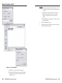
Front Panel Configuration Port
N The front panel configuration ports parallel the rear panel
Remote RS-232 ports. If a front panel configuration
connection is made on either unit, that unit's rear panel
Remote RS-232 port becomes inactive and the front panel
Configuration port is active.
The optional 9-pin D to 2.5 mm mini jack TRS RS‑232 cable,
part #70-335-01 (figure 4-2) can be used for connection to the
Configuration port.
The protocol for all ports is as follows:
•
9600 baud
•
no parity
•
1 stop bit
•
no flow control
•
6 feet
(1.8 m)
8 data bits
N For each unit, the rear panel Remote RS-232 port is active
only if the front panel Configuration port is not in use. If
a front panel configuration connection is made, the rear
panel Remote RS-232 port becomes inactive and the front
panel Configuration port is active.
1
Part #70-335-01
6
9
5
Tip
Ring
N Only one fiber optic cable, Optical 1, is required for video,
audio, and serial command transmission. But, if you
connect only one fiber optic cable, you will not receive
RS-232 reports from the controlled device, and there will be
reduced RS-232 command and Windows control program
functionality on the RX unit. To receive responses from
the controlled device and for full functionality, you will
need to install both fiber optic cables.
Rear Panel Remote RS-232 Ports
REMOTE
RS-232 ALARM
Tx Rx
1
Pin
TX
RX
Gnd
2
Function
Transmit data
Receive data
Signal ground
Do not tin the wires!
Ground ( )
Receive (Rx)
Transmit (Tx)
Bidirectional
Controlling
Device
Ground ( )
Receive (Rx)
Transmit (Tx)
Figure 4-1 — Remote connector pin assignments
4-2
FOX 500 Tx/Rx • Remote Control
Sleeve (Gnd)
9-pin D
Connection
TRS Plug
Pin 2
Pin 3
Pin 5
Computer's RX line
Computer's TX line
Computer's signal ground
Tip
Ring
Sleeve
Figure 4-2 — Optional 9-pin TRS RS-232 cable
Simple Instruction Set Control
Host-to-interface communications
SIS commands consist of one or more characters per field. No
special characters are required to begin or end a command
character sequence. When a command is valid, the unit executes
the command and sends a response to the host device. All
responses from the unit to the host end with a carriage return
and a line feed (CR/LF = ]), which signals the end of the
response character string. A string is one or more characters.
Symbol definitions
Symbols (variables), defined on the next page, are used
throughout the "Unit-initiated messages" section and the
command/response table on page 4-8. The symbols represent
variables in the unit-initiated messages and the command/
response table fields.
FOX 500 Tx/Rx • Remote Control
4-3
Remote Control, cont’d
Reconfig]
] = CR/LF (carriage return/line feed) (0x0D 0A)
•
X!
X@
X#
X$
X%
X^
X&
X*
= space
= Mute/auto image/front panel lock status
0 or 1 (0=off and 1=on)
= Output sync format
0 = RGBHV
1 = RGsB
= Output sync polarity
0 = follow input
1 = force sync to negative
= Horizontal and vertical position
= Horizontal start
0 to 255
= Pixel phase
0 to 31
= Total pixels
± 255 of the default value
=Sync frequency
xxx.xx (frequency in kHz [H]
or Hz [V])
X( = Memory preset number
X1) = Audio gain adjustment range
X1! = Audio attenuation adjustment range
X1@ = Audio level adjustment range
X1# = Output level
X1$ = Test pattern
X1% = Firmware version
X1^ = Link/input status
X1& = Mode
X1* = Transmitter or receiver
1 to 30
0 to 10
0 to -18
-18 to +10 (in 1.0 dB steps)
0 = consumer
1 = professional
0 = none
1 = Color Bars
2 = grayscale
3 = alternating pixels
v.vv
The unit sends the Reconfig message whenever the video input
signal to the transmitter is changed.
HphX$]
The unit sends the Hph message whenever the output's
horizontal position is shifted.
VphX$]
The unit sends the Vph message whenever the output's vertical
position is shifted.
HstX%]
The unit sends the Hst message whenever the output's
horizontal start is shifted.
TpxX&]
The unit sends the Tpx message whenever the total pixels
variable is changed.
PhsX^]
The unit sends the Phs message whenever the pixel phase
variable is changed.
SynX#]
0 = link or input not sensed
1 = link or input sensed
The unit sends the Syn message whenever the output video
format is changed.
SM = singlemode
MM = multimode
PolX#]
Tx = transmitter
Rx = receiver
Unit-initiated messages
When a local event, such as a front panel operation or error
condition, occurs, the unit responds by sending a message to the
host. The unit-initiated messages are listed below:
(c) Copyright 2006, Extron Electronics FOX 500 Tx,
Vx.xx,, 60-xxx-xx]]
- or (c) Copyright 2006, Extron Electronics FOX 500 Rx,
Vx.xx,, 60-xxx-xx]]
The connected unit issues the appropriate copyright message
(above) when it first powers on. Vx.xx is the firmware version
number, 60-xxx-xx is the connected unit's part number.
The unit sends the Pol message whenever the output sync
polarity setting is changed.
AudX1@]
The unit sends the Aud message whenever the input audio level
(gain and attenuation) is changed.
AmtX!]
The unit sends the Amt message whenever audio output is
muted or unmuted.
LvlX1#]
The unit sends the Lvl message whenever the audio output level
is changed.
SprX(]
The unit sends the Spr message whenever a preset is saved.
RprX1#]
The unit sends the Rpr message whenever a preset is recalled.
4-4
FOX 500 Tx/Rx • Remote Control
FOX 500 Tx/Rx • Remote Control
4-5
Remote Control, cont’d
Zpg]
The unit sends the Zpg message whenever all presets have been
erased.
ASCII to HEX Conversion Table
Space
ImgX!]
The unit sends the Img message (with the X! variable) whenever
the auto memory function has been toggled on or off.
Img]
The unit sends the Img message (with no variable) whenever the
auto image function has been triggered.
TstX1$]
The unit sends the Tst message whenever a test pattern has been
selected or test patterns are turned off.
1LnkX1^•2LnkX1^•RGBX1^•AudX1^]
The unit sends the status message whenever a change in the
fiber link and video and audio connection occurs.
Error responses
When the unit receives a valid SIS command, it executes the
command and sends a response to the host device. If the unit is
unable to execute the command because the command is invalid
or it contains invalid parameters, the unit returns an error
response to the host. The error response codes are:
E10 - Invalid command]
E11 - Invalid preset number]
E13 - Invalid parameter]
E14 - Invalid command for this configuration]
Timeout
Pauses of 10 seconds or longer between command ASCII
characters result in a timeout. The command operation is
aborted with no other indication.
Using the command/response table
The command/response table begins on page 4-8. Lower
case letters are acceptable in the command field except
where indicated for the audio level (gain and attenuation)
commands. Symbols are used throughout the table to represent
variables in the command/response fields. Command and
response examples are shown throughout the table. The ASCII
to HEX conversion table below is for use with the command/
response table.
4-6
FOX 500 Tx/Rx • Remote Control
FOX 500 Tx/Rx • Remote Control
4-7
4-8
B
Show video mute status
Video ouput mute status is X! (0 = unmuted, 1 = muted).
X!]
FOX 500 Tx/Rx • Remote Control
+H
-H
H
Increment position.
Decrement position
Show position
Shift the image one pixel to the left.
HphX$]
X$]
HphX$]
+/
-/
/
Decrement position
Show position
Shift the image down one line.
VphX$]
X$]
VphX$]
Set vertical centering to X$.
Shift the image up one line.
Additional description
VphX$]
(unit to host)
Response
-)
)
Decrement start position
Show start position
Shift the horizontal start position one pixel to the left.
HstX%]
X%]
Shift the horizontal start position one pixel to the right.
HstX%]
+U
-U
U
Increment pixel phase
Decrement pixel phase
Show pixel phase
FOX 500 Tx/Rx • Remote Control
Decrease pixel phase value by 1.
PhsX^]
X^]
Increase pixel phase value by 1..
PhsX^]
N When the controlling PC is connected to the receiver, the FOX 500 can perform this command only if the fiber 2 cable is connected. The unit
returns the E14 error if the fiber 2 cable is not connected.
Set a pixel phase value
X^U
PhsX^]
Set the pixel phase value to X^.
Example:
10U
Set the pixel phase value to 10.
Phs10]
Pixel phase
+)
Increment start position
N When the controlling PC is connected to the receiver, the FOX 500 can perform this command only if the fiber 2 cable is connected. The unit
returns the E14 error if fiber 2 is not connected.
Set a start position
Set the horizontal location of the first active pixel in the
X%)
HstX%]
active window.
Example:
128*)
Set pixel 128 as the first active pixel.
]
Hst128
Horizontal start
X$/
Increment position
(host to unit)
ASCII Command
Set a vertical position
Vertical shift
Command
Command/response table for SIS commands (continued)
X$H
Set a horizontal position
Set horizontal centering to X$.
Shift the image one pixel to the right.
7#
Receiver output sync (H and V for RGBHV, S for RGBS, or
s for RGsB) is always negative.
Output sync follows the video sync input to the
transmitter.
HphX$]
X#]
7*0#
Set output sync to follow
the input
Show the sync polarity
Horizontal shift
Pol0]
7*1#
Pol1]
X@]
Set the sync format. 0 = RGBHV, 1 = RGBS, 2 = RGsB.
Output video.
Blk0]
SynX@]
Blank the video output.
Additional description
Blk1]
(unit to host)
Response
Set output to sync negative
Output sync polarity
Show output sync format
Set output sync format
6*X@#
6#
0B
Output sync format
1B
Unmute output
(host to unit)
ASCII Command
Mute output
Video mute
Command
Command/response table for SIS commands
Remote Control, cont’d
4-9
4-10
(host to unit)
ASCII Command
(unit to host)
Response
Additional description
11#
Show total pixel value
FOX 500 Tx/Rx • Remote Control
X(,
X(.
TpxX&]
Command code is a comma.
Command code is a period.
SprX(]
RprX(]
X*,X*]
List the input frequency as X* kHz (horizontal) and X*
Hz (vertical.
Decrease total pixel value by 1 pixel.
TpxX&]
TpxX&]
Set the total pixel value to 15 pixels larger than the actual
resolution.
Increase total pixel value by 1 pixel.
Tpx+15
(host to unit)
ASCII Command
(unit to host)
Response
Additional description
40*0#
40*1#
40#
Set to consumer level
Set to professional level
Show audio output level
Audio output level
X1#]
Lvl1]
Lvl0]
Set the transmitter's audio output to the consumer
(–10 dBV) level.
Set the transmitter's audio output to the professional
(+4 dBu) level.
0 = consumer, 1 = professional.
Decrement audio input level from -08 dB to -9 dB.
G
Show input gain
Decrease the audio level by 1.0 dB.
Aud-09]
X1@]
-G
Example:
Increment the audio input level from +2 dB to +3 dB.
AudX1@]
-G
Aud+03]
Decrement level
Increase audio level by 1.0 dB.
AudX1@]
+G
+G
AudX1@]
X1!g
Example:
Set input audio attenuation
to - dB value
Increment level
N When the controlling PC is connected to the receiver, the FOX 500 can perform this command only if the fiber 2 cable is not connected. The
unit returns the E14 error if fiber 2 is not connected.
Set input audio gain to
X1)G
AudX1@]
+ dB value
Example:
2G
Set the input audio gain to +2 dB.
Aud+02.0]
N The set gain (G) and attenuation (g) commands are case sensitive.
Audio input gain and attenuation
Command
Command/response table for SIS commands (continued)
Recall preset
Save preset
Memory presets
View input frequency
1LS
11*-#
List sync frequency
11*+#
Decrement total pixel value
11*15#
Increment total pixel value
Example:
N When the controlling PC is connected to the receiver, the FOX 500 can perform this command only if the fiber 2 cable is connected. The unit
returns the E14 error if fiber 2 is not connected.
Set a total pixel value
Set the total pixels to a specific value.
11*X&#
TpxX&]
Total pixels
Command
Command/response table for SIS commands (continued)
Remote Control, cont’d
FOX 500 Tx/Rx • Remote Control
4-11
4-12
0Z
55#
Show auto memory status
Trigger auto image
FOX 500 Tx/Rx • Remote Control
0X
X
Unlock the front panel
Show the panel lock status
The receiver outputs audio.
X!]
Exe0]
Exe1]
Img]
X!]
Img1]
Img0]
Silence the receiver's audio output.
Amt0]
Additional description
Amt1]
(unit to host)
Response
(host to unit)
ASCII Command
(unit to host)
Response
Additional description
0J
J
Show test pattern status
3J
Output alt. pixels
Test pattern off
2j
Output grayscale
Set the receiver to output the alternating pixels test
pattern.
Set the receiver to output the input video (no test pattern
selected)
Tst3]
X1$]
Tst0]
Set the receiver to output the grayscale test pattern.
Tst2]
The test pattern will turn off if the input signal rate is changed or disconnected or if power is removed.
Output Color Bars
1J
Set the receiver to output the Color Bars test pattern.
Tst1]
N You must have a video input connected and fiber cable Optical 1 connected between the transmitter and receiver for the receiver to output a
selected test pattern.
Test pattern
Command
Command/response table for SIS commands (continued)
1X
Lock the front panel
Front panel lock (Executive mode)
55*2#
55*1#
Enable auto memory
Auto image
55*0#
Disable auto memory
Auto memory
1Z
Unmute the audio
(host to unit)
ASCII Command
Mute the audio
Audio mute
Command
Command/response table for SIS commands (continued)
Remote Control, cont’d
FOX 500 Tx/Rx • Remote Control
4-13
4-14
I
(host to unit)
ASCII Command
(unit to host)
Response
Additional description
FOX 500 Tx/Rx • Remote Control
1S
2S
3S
4S
Show link 2 status
Show input video status
Show input audio status
X1^]
X1^]
X1^]
X1^]
60-746-nn]
1.23]
0 = audio is not input to the transmitter, 1 = audio is input.
0 = video is not input to the transmitter, 1 = video is input.
0 = light link not received at transmitter, 1 = light received.
0 = light link not received at receiver, 1 = light received.
The factory-installed FOX 500 controller firmware version
is 1.23 (sample value only).
See appendix A for part numbers..
Reset all settings to the factory defaults.
Zpg]
Zpx]
EZG}
EZXXX}
Reset presets
System reset
Reset the audio input level at the transmitter to 0 dB and
the audio output level at the receiver to the consumer
(-10 dB) level.
Reset (erase) all memory presets.
Additional description
Zpa]
(unit to host)
Response
EZA}
(host to unit)
ASCII Command
Reset audio gain and
attenuation
Resets
Command
Command/response table for SIS commands (continued)
N
Show link 1 status
Q
Request part number
Example:
Information request
1LinkX1^•2LinkX1^•RGBX1^•AudX1^•X1&•X1*]
The unit responds with the current status (signal
detected) of optical link 1, optical link 2, the video input,
the audio input, the fiber optic mode (singlemode or
multi mode), and the device type (Tx or Rx).
N The receiver monitors the fiber 1 cable. If the PC is connected to the transmitter and fiber cable 2 is not installed, for the information request
(I) and Status commands (S) below, the transmitter reports 1Link0 regardless of the status of the fiber 1 cable.
Show firmware version
Q
X1%]
Information requests
Command
Command/response table for SIS commands (continued)
Remote Control, cont’d
FOX 500 Tx/Rx • Remote Control
4-15
Remote Control, cont’d
Windows®-Based Program Control
The Extron FOX 500 Control Program, which communicates
with the transmitter and receiver pair via either unit's rear panel
Remote RS-232 port or front panel Configuration port, provides
an easy way to operate the pair.
2.
Select the Com port to which your transmitter or receiver
is connected. Click OK.
The FOX 500 Control Program window appears (figure 4-4).
The program is compatible with Windows 2000, Windows XP,
or later. Updates to this program can be downloaded from the
Extron Web site (http://www.extron.com).
Installing the software
The program is contained on a CD-ROM. To install the
software, insert the CD-ROM into the drive. The setup
program should start automatically. If it does not self-start, run
Launch.exe from the CD and follow the instructions that appear
on the screen. By default, the Windows installation creates a
C:\Program Files\Extron\FOX500 directory, and it places two
icons into a group folder named “Extron Electronics\FOX 500.”
The two installed icons are:
•
FOX 500 Control Pgm
•
Uninstall FOX 500
Starting the program
Start the Extron FOX 500 Control Program as follows:
1.
Click Start > Programs > Extron Electronics >
FOX 500 > FOX 500 Control Pgm.
Figure 4-4 — FOX 500 Control Program window
The Communication Setup window appears
(figure 4-3).
N Only one fiber optic cable, Optical 1, is required for video,
audio, and serial command transmission. But, if you
connect only one fiber optic cable, you will not receive
RS-232 reports from the controlled device, and there will
be reduced Windows-based control program functionality
on the Rx unit. To receive responses from the controlled
device and for full functionality, you will need to install
both fiber optic cables.
Figure 4-3 — Communication Setup window
4-16
FOX 500 Tx/Rx • Remote Control
FOX 500 Tx/Rx • Remote Control
4-17
Remote Control, cont’d
Status area
The status area provides visual indications of the connection
status. These indications are similar to the front panel
indications described in chapter 3, "Operation".
•
•
RGB present indicator — This indicator is green when
the transmitter detects a sync signal on its video input:
•
Horizontal sync (H) (for RGBHV video)
•
Composite sync (S) (for RGBS video)
•
Green (Sync on green) (G) (for RGsB or RsGsBs
video)
Audio present indicator — This indicator is green when
the transmitter detects a low level audio signal for a short
period of time. This indicator goes dark if the audio
signal drops below the minimum threshold for a short
period of time.
Mute area
Click the Video Mute and/or Audio Mute radio buttons in the
Mute area to turn the video and/or audio mutes on and off.
N When the video output is muted, the receiver mutes the
red, green, and blue planes, but leaves the sync plane(s)
(horizontal and vertical or composite sync) live so that
there is no loss of sync in the display device.
N When you mute or unmute the output, the setting is
changed in the receiver. It reports the changes to the
transmitter via the optional Optical 2 cable.
Link 1 indicator — This indicator is green when the receiver
detects light on the fiber optic cable Optical 1.
N The receiver detects the Optical 1 light. It reports the
status to the transmitter via the optional Optical 2 cable.
If you are connected to either of the transmitter's serial
ports, and the Optical 2 cable is not connected in your
system, the control program's Link 1 indicator will not
show green (detected) whether the receiver detects the link
or not.
Figure 4-5 — Alternate Mute area indication
Video Adjustment area
The Video Adjustment area provides slider controls that let you
change the following video parameters:
Link 2 indicator — This indicator is green when the
transmitter detects light on the fiber optic cable Optical 2.
•Horizontal shift (position)
N The transmitter detects the Optical 2 light. It reports the
•Horizontal start
status to the receiver via the Optical 1 cable.
If you are connected to either of the receiver's serial
ports, and the Optical 1 cable is disconnected, the control
program's Link 2 indicator will not show green (detected)
whether the transmitter detects the link or not.
The Status area also shows to which unit the controlling PC is
connected, the FOX 500 model (multimode or singlemode), and
the video input frequency.
Memory Preset area
The Memory Preset area provides a means to save and recall
memory presets. Memory presets are saved values of the
horizontal and vertical position and sizing information. See
"Memory Presets menu" in chapter 3, "Operation", for more
information on presets.
4-18
If you are connected to either of the transmitter's serial
ports, and the Optical 2 cable is not connected in your
system, you can still mute the output in the control
program's Mute area, but the program cannot report
the position values. The Set video (or audio) mute On
or Off message is displayed for approximately 1 second
(figure 4-5).
FOX 500 Tx/Rx • Remote Control
•Vertical shift (position)
•Pixel Phase
•Total pixels
N When you make changes to the horizontal start, pixel
phase, or total pixels settings, the value is changed in the
transmitter.
If you are connected to either of the receiver's serial
ports, and the Optical 2 cable is not connected in your
system, you cannot change these values using the
control program. These slider controls are grayed out
(unavailable).
FOX 500 Tx/Rx • Remote Control
4-19
Remote Control, cont’d
N When you make horizontal or vertical position changes
(shift the image), the setting is changed in the receiver. It
reports the shift values to the transmitter via the optional
Optical 2 cable.
If you are connected to either of the transmitter's serial
ports, and the Optical 2 cable is not connected in your
system, you can still shift the image in the control
program's Video Adjustment area, but the program
cannot report the position values.
Output Configuration area
Sync Format radio buttons — Click either the RGBHV/RGBS
or RGsB radio button to select the desired video output sync
format.
Output Polarity radio buttons — Click either the Follow input
sync or Force sync to negative radio button to select the desired
video output sync polarity.
N When you make output configuration changes, the setting
is changed in the receiver. It reports the changes to the
transmitter via the optional Optical 2 cable.
If you are connected to either of the transmitter's serial
ports, and the Optical 2 cable is not connected in your
system, the program cannot report the output sync format
and polarity position settings in the control program's
Video Adjustment area. You can change the output sync
format and polarity, but the program cannot report the
changes.
Advanced Configuration area
Executive Mode button — Click the Executive Mode radio
button to toggle the front panel lock on and off.
N When you toggle the front panel lock on and off, the setting
is changed in the receiver. It reports the changes to the
transmitter via the optional Optical 2 cable.
4-20
If you are connected to either of the transmitter's serial
ports, and the Optical 2 cable is not connected in your
system, you can still toggle the front panel lock in the
control program's Advanced Configuration area, but the
program cannot report the lock's status. The program
indication changes (figure 4-6) to show that the Executive
mode is control only, without and indication of the current
mode. The Set executive mode On or Off message is
displayed for approximately 1 second.
FOX 500 Tx/Rx • Remote Control
Figure 4-6 — Alternate Advanced Configuration area
indication
Auto Memory checkbox — Click the Auto Memory checkbox
to automatically apply saved position, horizontal start,
total pixels, and pixel phase settings when the sensed input
resolution changes. See "Auto Memory submenu" in chapter 3,
"Operation" for more details about the auto memory function.
Auto Image button — Click the Auto Image button to adjust
the output settings for the best image, based on the sensed input
resolution.
Test Patterns drop box — Select one of three built-in test
patterns; Color Bars, grayscale, and alternating pixels; as
necessary to help adjust the display's color, focus, and grayscale.
Select Off to output the video input to the transmitter.
N You must have a video input connected and fiber cable
Optical 1 connected between the transmitter and receiver
for the receiver to output a selected test pattern.
The test pattern will turn off if the input signal rate is
changed or disconnected or if power is removed.
Audio Adjustment area
Audio Gain/Attenuation slider — Click and drag the Audio
Gain/Attenuation slider control to select the input audio gain or
attenuation value, from -18 dB to +10 dB in 1.0 dB increments.
N When you make input gain or attenuation changes, the
setting is changed in the transmitter.
If you are connected to either of the receiver's serial ports,
and the Optical 2 cable is not connected in your system,
you cannot change the input value from the control
program's Audio Adjustment area.
FOX 500 Tx/Rx • Remote Control
4-21
Remote Control, cont’d
Audio Output Level area
Audio Output Level radio buttons — Click either the
Consumer Level (-10 dBV) or Professional Level (+4 dBu) radio
button to select the output audio level.
N When you make an audio output level change, the setting
is changed in the receiver. It reports the changes to the
transmitter via the optional Optical 2 cable.
4-22
If you are connected to either of the transmitter's serial
ports, and the Optical 2 cable is not connected in your
system, the program cannot report the output audio level
in the control program's Audio Adjustment area. You
can change the level, but the program cannot report
the changes. The program shows the Set Consumer
(or Professional) level message to indicate that the
output level command is control only, not and indication
(figure 4-7). The message is displayed for approximately
1 second.
Firmware upgrade
Firmware can be upgraded for each unit via either of that unit's
serial ports by calling the Extron Firmware Loader utility from
the Windows-based control program.
N When firmware upgrades are available, they are unique to
the unit; a transmitter firmware upgrade for the Tx unit
and a receiver upgrade for the Rx unit.
You must connect directly to the unit to be updated.
Upload replacement firmware as follows:
1.
Visit the Extron web site, www.extron.com, click the
Download Center tab, and then click the Firmware link
(figure 4-8). Select the appropriate firmware file(s) to
download and copy it (them) to your computer. Note the
folder to which you save the firmware file(s).
Figure 4-8 — Location of firmware upgrade files
Figure 4-7 — Alternate Audio Adjustment area
indication
2.
In the Windows Explorer or other file browser, double-click
the downloaded executable (*.exe) file(s) to self-extract the
firmware file(s).
3.
Connect a Windows-based computer to the either
serial port (rear panel Remote RS-232 or front panel
Configuration) of the unit to be updated. See chapter 2,
"Installation", for more details.
4.
Start the FOX 500 Control Program. See "Starting the
program", on page 4-16.
5.
Click Tools > Update Firmware. The Extron Firmware
Loader appears (figure 4-9).
FOX 500 Tx/Rx • Remote Control
FOX 500 Tx/Rx • Remote Control
4-23
Remote Control, cont’d
N Valid firmware files must have the file extension “.BIN”. Any other file extension is not a firmware upgrade for your
FOX 500.
c. Click Upload. The File Loader reports, "This process
could take several minutes. Please wait..." and then
displays a scroll bar that shows the status of the
upload.
d. When the Firmware Loader reports, "Transfer complete!",
click the Exit button.
6.
Cycle the FOX 500 unit's power.
7.
If necessary, repeat this entire procedure on the other unit
of the transmitter/receiver pair.
Figure 4-9 — Open window
a. Click Browse. The open file window appears.
b. Navigate to the folder where you saved the firmware
upgrade file. Select the file. The Firmware Loader
returns to the top.
4-24
FOX 500 Tx/Rx • Remote Control
FOX 500 Tx/Rx • Remote Control
4-25
Remote Control, cont’d
FOX 500 Tx/Rx
A
Appendix A
Reference Information
Specifications
Part Numbers
4-26
FOX 500 Tx/Rx • Remote Control
Reference Information
Specifications
N
The FOX 500 Tx/Rx consists of a transmitter (FOX 500 Tx)
and a receiver (FOX 500 Rx) with one or two fiber optic cables
linking the two units.
The analog RGB input signal is digitized pixel by pixel in the
transmitter, sent digitally through the fiber cable, and converted
back to analog RGB in the receiver.
The analog audio signal(s) is (are) digitized in the transmitter,
sent through the fiber cable, and converted back to analog audio
in the receiver.
Optical fiber interconnection between transmitter and
receiver
Number/type................................. 1 or 2 fiber optic
N
Only one fiber is required to transmit video, audio, and
unidirectional data. A second fiber is required to transmit
return data for bidirectional control/communication.
Connectors...................................... 2 LC connectors
Operating distance......................... 30 km (18.75 miles) with singlemode (SM)
cables with a FOX 500 Tx/Rx SM
0.5 km (0.3 mile) with multimode (MM)
cables with a FOX 500 Tx/Rx SM
0.15 km (450') with multimode (MM)
cables with a FOX 500 Tx/Rx MM
N
Operating distance is approximate. These are typical
distances. The maximum distance may be greater than these
typical numbers depending on factors such as fiber type, fiber
bandwidth, connector splicing, losses, modal or chromatic
dispersion, environmental factors, and kinks.
Nominal peak wavelength........... 850 nm for FOX 500 Tx/Rx MM,
1310 nm for FOX 500 Tx/Rx SM
Transmission power....................... -5 dBm, typical
Maximum receiver sensitivity...... -18 dBm, typical
Optical budget................................ 13 dB, maximum
N
A-2
Video
Number/signal type...................... 1 VGA-UXGA RGBHV, RGBS, RGsB,
RsGsBs input
1 VGA-UXGA RGBHV, RGBS, RGsB,
RsGsBs loop-through
Gain.................................................. Unity
Pixel data bit depth........................ 8 bits per channel, 3 channels (R, G, and B)
Maximum resolution..................... 1600 x 1200 @ 60 Hz, digitized pixel by
pixel; higher resolutions up to 2048 x 1120,
undersampled
Video input and loop-through — transmitter (FOX 500 Tx)
Number/signal type...................... 1 VGA-UXGA RGBHV, RGBS, RGsB,
RsGsBs input
1 VGA-UXGA RGBHV, RGBS, RGsB,
RsGsBs loop-through
Connectors...................................... 1 x 5 female BNC or (1) female 15-pin HD
for input
(1) female 15-pin HD for loop-through
Nominal level................................. 0.7 Vp-p for RGB
Minimum/maximum levels......... Analog: 0.3V to 1.5 Vp-p with no offset
Impedance....................................... 75 ohms
Horizontal frequency..................... 24 kHz to 100 kHz
Vertical frequency........................... 40 Hz to 120 Hz
Return loss....................................... <-40 dB @ 5 MHz
Video output — receiver (FOX 500 Rx)
Number/signal type...................... 2 VGA-UXGA RGBHV, RGBS, RGsB,
RsGsBs (follows input or can be set by
user)
Connectors...................................... 1 x 6 female BNC and (1) female 15-pin HD
Nominal level................................. 0.7 Vp-p for RGB
Minimum/maximum levels......... 0.3 V to 1.5 Vp-p
Impedance....................................... 75 ohms
Return loss....................................... -40 dB @ 5 MHz
DC offset.......................................... ±5 mV with input at 0 offset
These transceivers are class 1 laser products. They meet the
safety regulations of IEC-60825, FDA 21 CFR 1040.10, and
FDA 21 CFR 1040.11.
FOX 500 Tx/Rx • Reference Information
FOX 500 Tx/Rx • Reference Information
A-3
Reference Information, cont’d
Sync
Audio output — receiver (FOX 500 Rx)
Input type........................................ Autodetect RGBHV, RGBS, RGsB, RsGsBs
Output type..................................... RGBHV, RGBS, RGsB, RsGsBs
(follows input or can be set by user)
Input level....................................... 2.5 V to 5.0 Vp-p
Output level.................................... TTL: 5.0 V p-p, unterminated, in HV or S;
or 0.3 V p-p on Gs, terminated
Input impedance............................ 510 ohms
Output impedance......................... 75 ohms
Polarity............................................ Positive or negative (follows input or can
be set by user)
Audio
Number/signal type...................... 2 inputs (mixed): 1 balanced stereo,
1 unbalanced stereo
Gain
Range................................... Adjustable, -18 dB to +24 dB
Default................................. Unbalanced output: -6 dB;
balanced output: 0 dB
Frequency response....................... 20 Hz to 20 kHz, ±0.5 dB
THD + Noise................................... 0.10% @ 1 kHz at nominal level
S/N................................................... >80 dB at maximum output (unweighted)
CMRR............................................... >65 dB @ 20 Hz to 20 kHz
Sample size...................................... 18 bits per channel, 2 channels (L and R)
Sampling rate.................................. 48 kHz
Audio input — transmitter (FOX 500 Tx)
Number/signal type...................... 2 inputs (mixed): 1 balanced stereo,
1 unbalanced stereo
Connectors...................................... (1) 3.5 mm captive screw connector, 5 pole
(1) 3.5 mm mini stereo jack
Impedance....................................... 18k ohms unbalanced, 20k ohms balanced,
DC coupled
Nominal level................................. +4 dBu (1.23 Vrms), -10 dBV (316 mVrms)
Maximum level............................... +17 dBV, (unbalanced) at 1% THD+N
N
A-4
0 dBu = 0.775 Vrms, 0 dBV = 1 Vrms, 0 dBV
FOX 500 Tx/Rx • Reference Information
2 dBu
Number/signal type...................... 2 buffered outputs: 1 balanced stereo, 1
unbalanced stereo
Connectors...................................... (1) 3.5 mm captive screw connector, 5 pole
(1) 3.5 mm mini stereo jack
Impedance....................................... 50 ohms unbalanced, 100 ohms balanced
Nominal level................................. +4 dBu (1.23 Vrms), -10 dBV (316 mVrms)
Maximum level (Hi-Z).................. >+19 dBu, unbalanced at 1% THD+N
Maximum level (600 ohm)............ >+15 dBm, unbalanced at 1% THD+N
Control/remote
Serial control ports on each unit (transmitter and receiver)
Control................................. 1 RS-232, 3.5 mm captive screw connector,
5 pole (3 pins are used) (rear panel)
1 RS-232, 2.5 mm mini stereo jack (front
panel)
Pass-through....................... 1 RS-232, 3.5 mm captive screw connector,
5 pole (3 pins are used) (rear panel);
in parallel with 1 RS-232, 2.5 mm mini
stereo jack (front panel)
Baud rate and protocol
Control................................. 9600 baud, 8 data bits, 1 stop bit, no parity
Pass-through....................... 9600 to 38400 baud
Serial control pin configurations
Captive screw connectors: 1 = Tx, 2 = Rx,
3 = GND
Mini stereo jack: tip = Tx, ring = Rx,
sleeve = GND
Program control.............................. Extron’s control/configuration program
for Windows®
Extron’s Simple Instruction Set (SIS™)
General
Power............................................... 100 VAC to 240 VAC, 50/60 Hz, 11 watts,
internal, autoswitchable
Temperature/humidity................. Storage: -40 to +158 °F (-40 to +70 °C) /
10% to 90%, noncondensing
Operating: +32 to +122 °F (0 to +50 °C) /
10% to 90%, noncondensing
Rack mount..................................... Yes, with optional 1U rack shelf, part
#60-190-01 or 60-604-01
Furniture mountable with optional under
desk mounting kit, part #70-077-01
Enclosure type................................ Metal
FOX 500 Tx/Rx • Reference Information
A-5
Reference Information, cont’d
Enclosure dimensions.................... 1.7" H x 8.7" W x 9.5" D
(1U high, half rack wide)
4.3 cm H x 22.1 cm W x 24.1 cm D
(Depth excludes connectors and knobs.)
Product weight............................... 4.6 lbs (2.1 kg) per Tx/Rx pair
Shipping weight............................. 8 lbs (4 kg) per Tx/Rx pair
Vibration.......................................... ISTA 1A in carton
(International Safe Transit Association)
Listings............................................ UL, CUL
Compliances.................................... CE, FCC Class A, VCCI, AS/NZS, ICE
MTBF................................................ 30,000 hours
Warranty.......................................... 3 years parts and labor
N
All nominal levels are at ±10%.
N
Specifications are subject to change without notice.
Included parts
These items are included in each order for a FOX 500 Tx/Rx:
Included parts
IEC power cord
Tweeker (small screwdriver)
User’s guide
Captive screw 5-pole connectors (qty. 6)
FOX 500 part numbers
N The FOX 500 Tx and FOX 500 Rx are a paired set,
sharing a common serial number.
10-703-12
(2) 10' LC-LC duplex patch cables
(SM or MM, depending on the model)
Optional accessories
Accessories
Part Numbers
Part number
Part number
9-pin D to 2.5 mm mini jack TRS RS‑232
cable
70-335-01
RSU 129 9" 1U universal rack shelf kit
60-190-01
RSB 129 9" 1U basic rack shelf
60-604-01
MBU 125 under desk mounting kit
70-077-01
MBD 129 through desk mounting kit
70-077-02
N When returning a FOX 500 Tx or FOX 500 Rx to Extron
for service, ensure that the identically serial-numbered
paired half is also returned.
The FOX 500 is available in singlemode (SM) and
multimode (MM) models, each of which includes a transmitter
(Tx) and a receiver (Rx):
A-6
FOX 500 Models
Part number
FOX 500 Tx/Rx SM
60-746-02
FOX 500 Tx SM
60-746-12
FOX 500 Rx SM
60-746-22
FOX 500 Tx/Rx MM
60-746-01
FOX 500 Tx MM
60-746-11
FOX 500 Rx MM
60-746-21
FOX 500 Tx/Rx • Reference Information
FOX 500 Tx/Rx • Reference Information
A-7
Reference Information, cont’d
Cables
Accessories
A-8
Part number
VGA M-M MD,
3' to 100' (0.9 m to 30.4 m) (molded)
26-238-nn
VGA M-M BK,
3' to 100' (0.9 m to 30.4 m) (backshell)
26-238-nn
VGAP M-M MD,
3' to 25' (0.9 m to 7.6 m) (molded)
26-439-nn
VGAP M-M BK,
35' to 100' (10.6 m to 30.4 m) (backshell)
26-439-nn
VGA-A M-M MD (with audio),
3' to 50' (0.9 m to 15.2 m) (molded)
26-490-nn
VGA-A M-M BK (with audio),
3' to 50' (0.9 m to 15.2 m) (backshell)
26-490-nn
MHR-5 BNC mini high resolution
male to male, 3' to 100' (0.9 m to 30.4 m)
26-260-nn
MHR-5P BNC mini high resolution plenum
male to male, 3' to 100' (0.9 m to 30.4 m)
26-378-nn
M59-5 BNC mini 59 flex
male to male, 3' to 100' (0.9 m to 30.4 m)
26-499-nn
RG6-5 BNC super high resolution
male to male, 3' to 100' (0.9 m to 30.4 m)
26-369-nn
FOX 500 Tx/Rx • Reference Information