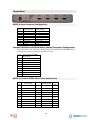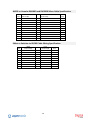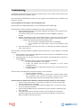
1
Digital Solutions
BVE02
ESAM Interface
Owner’s Manual
January 2010
OPERATIONAL OVERVIEW
4
BVE02-PV
BVE02-AFV
4
4
Basic Operation
Preview and Monitor Operations
Channel Fader Level Adjustments
Mixer ESAM Control Enable
Master Fader Control
4
5
6
6
6
BVE02-PV
Preview Audio Control
Remote Preview Control
Multiple Audio Sources
7
7
7
7
SET-UP
8
Yamaha Mixer Setup
Mixer Configuration
BVE02 Interface
BVE02-PV
8
8
10
10
EDIT CONTROLLER SETUPS
11
Sony BVE9100
Sony BVE2000
SONY BVE910
System Configuration Security
11
12
12
12
MONITORING
13
Edit Suite Monitoring
Very Simple Monitoring
Simple 2 Channel Monitoring
Sophisticated 4 or 8 Channel Monitoring
13
13
13
13
Edit Suite Monitoring Operation
Monitor
Edit Preview
Edit
14
14
14
14
LIVE MONITOR SETUP WITH BVE02-PV
15
LIVE STUDIO GALLERY MONITOR OPERATION
15
Program Monitor
Audio Preview Monitor
15
15
INTERNAL DIP SWITCH SETUP
16
MACHINE ASSIGNMENTS
16
2
CONNECTIONS.
17
BVE02 D-type Connector Configuration.
Yamaha DM1000 and DM2000 Mixer Remote Connector Configuration
BVE02 to Yamaha 02R96 Mixer Cable Specification
BVE02 to Yamaha DM1000 and DM2000 Mixer Cable Specification
Editor or Switcher to BVE02 Cable Wiring Specification
17
17
17
18
18
TROUBLESHOOTING.
19
UPLOADING NEW CODE TO THE BVE02
21
Uploading New Code
21
APPENDIX A - ELECTROMAGNETIC COMPATIBILITY
24
3
Operational Overview
The Digital Solutions BVE02 interface enables a Yamaha DM1000, 02R96 or DM2000 digital
recording console to be controlled by a Video Edit Controller or Vision Switcher using the
ESAM command protocol.
When connected to a Video Edit Controller, the mixing and monitoring of forty channels of
source audio may be controlled directly from the edit controller, with all edits and crossfades
stored and recalled as part of the edit decision list (EDL) held on the Edit Controller.
When connected to a Vision Switcher, the BVE02 automatically mixes the audio channels for
sources selected to the Program bus on the Vision Switcher.
In both scenarios, the audio mixer may be used with two or four audio-channel VTRs, servers,
cameras or Outside Sources and will mix signals to a two, four or eight channel mix bus.
The versatile system display and the motorised channel faders of the mixer enable the status
of the mixing, controlled by the edit controller or visions switcher to be easily observed.
BVE02-PV
The BVE02-PV adds the ability for sources opened to a Vision Switcher’s Preset bus to be
auditioned on the audio mixer and the fader levels for that source adjusted before the source
is opened to the Program bus. Uniquely, when the BVE02-PV is connected to a Snell Kahuna
Vision Switcher, it also allows multiple sources to be opened simultaneously to the program
bus of the audio mixer.
The BVE02-PV is ideally suited to single-operator galleries, such as those used for local news
or magazine programming, where one person is responsible for both vision and audio mixing.
BVE02-AFV
The BVE02-AFV allows the creation of a complete audio mix, using all the faders of the mixer,
for each vision source. The BVE02-AFV includes an external control panel that gives quick and
simple control of the system for creating and updating each mix, whether during offline
preparation or while on-air.
The BVE02-AFV is most effectively employed in the production of fast-moving sports
programming such as motor sport, skiing, air shows or air racing.
Basic Operation
When executing edit transitions, crossfades or cuts under the control of the Edit Controller or
production Vision Switcher, the mixer operates in a very similar manner to a video switcher. In
order to simplify the selection and control of the mixer channels, the group of inputs which
carry the audio signals from an individual VTR, server channel or other video source are
considered as a single entity and are referred to as a Machine. The channels which make up a
Machine are listed in the ‘Machine Assignments’ section of this manual.
The Edit Controller will have a configuration page which holds information on each VTR it is to
control, including the Machine control port number, the video switcher input number, and the
audio mixer Machine number for each source. The Vision Switcher in a production gallery or
OB truck will have a similar configuration page identifying each connected source and either
4
the matching audio Machine number for a set of adjacent channels on the mixer or individual
channels if these are spread across the mixer.
In the edit suite, when executing “A/B Roll” edits the Edit Controller will select the source (or
FROM) Machine which is to be heard prior to the edit transition point.
When this selection is received from the Edit Controller, the interface will cause the mixer to
open the set of channel faders which represent the inputs for the FROM Machine. The audio
from this Machine will be sent to the main Program mix buses.
The Edit Controller will also select a destination (or TO) Machine (to be heard after the edit
transition has been completed), and a transition duration time in frames. This information is
stored within the BVE02 interface.
At the appropriate time, the edit controller will issue a command to start the transition. The
BVE02 will then control the channel faders of the mixer to smoothly crossfade from the FROM
source Machine to the TO source Machine.
This transition may be observed by the changing positions of the motorised channel faders on
the mixer. At the end of the transition time the audio from the destination Machine will be
heard on the main mix buses.
In the Production Gallery, the process is very similar with the source currently open to the
Program bus defined as the FROM source and the next vision source To Air on the Preset bus
as the TO source. The audio crossfade from the channels of the FROM source to the channels
of the TO source is triggered by the Auto key or T-bar on the Vision Switcher.
Once the transition or crossfade is completed, the designation of the new Machine on the
Program bus is now changed to FROM and the next source on the Preset bus as the new TO,
ready for the process to be repeated.
Preview and Monitor Operations
Video Edit Controllers generally consider that their control of the VTRs, the video switchers,
and audio mixers will be in one of three states:Monitor
The operation of the VTRs, video switcher, and audio mixer is controlled by the manual
operation of the Edit Controller. This is the mode used to find and mark edit points.
Preview
The operation of the VTRs, video switcher, and audio mixer is directly controlled
by the Edit Controller according to automatic execution of EDL commands
without the result being actually recorded by the Record VTR(s). This is
sometimes called Edit (Rehearse).
Edit
The operation of the VTRs, video switcher, and audio mixer is directly controlled
by the Edit Controller according to automatic execution of EDL commands with
the result being recorded by the Record VTR(s). This is sometimes called Edit
(Execute).
While the operation of the audio mixer during Edit mode operations has been already
described, the precise operation of the audio mixer during Preview and Monitor mode
operations varies according to the setup of the Edit Controller. It is therefore crucial that the
5
edit controller and BVE02 are configured correctly to provide the required Preview and Edit
monitoring.
The last 2, 4 or 8 channels of the mixer and the output routing are employed as a monitor
matrix to generate the corresponding number of monitor channels. For greatest flexibility in
how the monitoring may be configured, these are kept discrete and delivered to the Omni
outputs of the mixer. These may be fed to individual speakers and meters or mixed externally
into a stereo or four-channel monitoring/metering system.
Channel Fader Level Adjustments
The nominal level of each input channel of the mixer may be adjusted either remotely from
the Edit Controller, or locally using the faders on the mixer itself. By default the faders for a
selected Machine will move to the unity gain (0 dB) position. These fader levels may be
altered to suit the programme material and any changes will be stored automatically. Any
subsequent command from the Editor to open or fade up these faders will cause them to rise
to the most recently stored levels.
These changes may be captured and stored as E-MEM data by the Edit Controller. This feature
allows the nominal fader levels of a Machine to be stored and recalled by the Edit Controller
on an edit-by-edit basis.
E-MEM stores and recalls are normally initiated by the operation of the Edit Controller. This is
sometimes referred to as MXMEM Learn. Some Edit Controllers will store E-MEM data if the
ESAM mixer initiates the data transfer.
The BVE02 interface monitors which Source VTRs are included in an edit and the tracks which
are being edited on the Recorder. BVE02 will only control input channels of the Source VTRs
which are being routed, by the mixer’s channel-to-bus routing section, to the tracks being
edited on the Recorder.
Hence any channels which are not routed at all or are routed to tracks which are not being
edited will not be opened during Monitoring, Preview or Edit operations.
Mixer ESAM Control Enable
The control of the mixer by the BVE02 is enabled according to the state of the Automix
ENABLE/DISABLE button on the AUTOMIX Main page, reached by pressing the AUTOMIX
button of the mixer control surface.
ESAM control is ENABLED when ENABLED is displayed.
Master Fader Control
The BVE02 links the Master fader on control surface to the bus faders, so operating the
Master fader will also operate the bus output faders.
This provides a simple way of adjusting the overall audio level fed to the recorder in an edit
suite or the transmission path or fade out the audio at the end of the programme or news
bulletin.
6
BVE02-PV
When connected directly to a Vision Switcher, the BVE02-PV adds a number of significant
additional functions to the standard facilities described above that extend the audio control in
live TV production – especially for News and Magazine programming where single-person
video and audio operation is often preferred.
Preview Audio Control
When a vision source is selected to the Preset bus on the Vision Switcher, the corresponding
audio sources are routed to the inputs of the last 2, 4 or 8 channels of the mixer. When Audio
Preview is selected on the Vision Switcher the BVE02-PV allows the faders of these channels
to be adjusted while the audio is heard and metered through the external monitoring system.
Once the correct fader levels have been set the fader levels for that source are stored within
the BVE02-PV. When that video and audio source is selected to the Program bus, the fader
levels are recalled and applied to the faders of the channels carrying that source’s audio.
While that source is selected to the Program bus, if the audio levels require further
adjustment, reselecting that source to the Preset bus will enable the audio levels to be
adjusted from the Preview faders on the mixer while the source is To Air.
Remote Preview Control
As the layout of a production gallery will have to accommodate both multi-operator and
single-operator working, it is often not practical to make the audio mixer and Vision Switcher
easily accessible from a single operator position.
The BVE02-PV therefore allows a compact external fader unit, specifically the JLCooper
ES4/100-RS422, to be connected that can be conveniently installed beside the Vision
Switcher, within easy reach of the Vision Switcher operator. This fader unit replicates the
function of the Preview faders of the mixer, allowing a single operator to select vision sources
and control the corresponding audio channels.
Multiple Audio Sources
The standard ESAM protocol allows for only one Machine group of sources to open to the
Program bus at one time – except when a transition is in progress from one Machine source
to another.
Exclusive to systems incorporating Snell Kahuna Vision Switchers, the BVE02-PV allows
multiple vision sources to be selected to the Program bus and all the corresponding audio
channels to be simultaneously opened on the mixer.
This is especially important for News or Magazine programming where the programme
requires, for example, the automated mixing of an interview or conversation between two
remote contributors or a studio presenter and a succession of remote contributors.
7
Set-up
Yamaha Mixer Setup
Before the mixer can be usefully commanded by the edit controller, the appropriate audio
connections to the source Machines, recorders, and monitor system should be established.
The mixer must be fitted with the required type and quantity of optional I/O cards to interface
to the surrounding audio infrastructure.
The feed to the record VTR(s) or To Air should be taken from output buses 1 to 2, 4 or 8 which
are connected, using the Output Matrix of the mixer (accessed via the Output Patch key), to
the appropriate output ports for your recorder or transmission path.
Similarly, the source audio should be connected to input ports on the mixer or optional I/O
cards and routed to the correct mixing channels using the Input matrix (accessed via the Input
Patch key).
To employ the simpler Machine assignment of audio channels to a video source, input source
signals should be connected to pairs, or groups of four or eight mixer channels with regard to
the ESAM Machine assignments listed in the ‘Machine Assignments’ section of this manual.
For initial setup, all the channels should be setup with EQ set to flat and dynamics processing
switched out.
While the pan control of each channel can be adjusted to taste, most edit suite and gallery
mixers are configured with the pan controls set fully left or right. This not only ensures the
input channel is only routed to a single output bus, it also delivers the signal at the correct
level, which is particularly important if the input signals are to be passed directly through the
mixer at unity, such as when compiling a transmission file or tape, or in a live transmission
suite where audio is already at transmission level.
If the setup requires channels to be centre panned, to ensure unity gain through the channel
with the fader at the 0dB position, the Nominal Pan setting must be deselected in Preferences
page 1.
The audio monitoring and metering system input should be fed from the first 2, 4 or 8 Omni
outputs of the mixer, and basic operation of the inputs and monitoring checked to ensure that
input signals can be heard properly. Main mix output will come from buses 1 to 8 routed via
the Output Matrix to the ports connected to the Recorder or the To Air transmission path.
Once basic operation has been tested, an initial, overall setup for the mixer can will be created
that will configure it correctly for edit suite or studio gallery operation and control by the
BVE02. This setup will be stored in a scene memory for recall to reset the mixer to a known
state when under ESAM control.
Mixer Configuration
Recall the Initial Data scene memory (0) using the Scene Memory selection and RECALL key.
Select the Master fader layer and check/set the bus, Aux and Master output faders to
0dB/Unity.
Set bus 1-4 or 1-8 delay to: ON; msec: 0.2; Samples: 8.
Set Nominal Pan: ON (Preferences page 1)
8
For 4-ch operation set channels 45-48 (DM1000), 53-56 (02R96) or 93-96 (DM2000);
or for 8 channel operation channels 41-48 (DM1000) 49-56 (02R96) or 89-56 (DM2000) as
follows:
Insert:
EQ:
DELAY:
On/Off: ON; Out: NONE;
In: NONE; Position: POST-FADER.
OFF
ON, msec: 0.5; samples: 24; Mix: +100%; FB Gain: 0%.
Set bus 1-4 or 1-8 delay to: ON; msec: 0.2; Samples: 8
IMPORTANT: These channels, with the output routing, create a monitor matrix for feeding
signals from the edit recorder or a Previewed Machine to the external monitoring system.
Therefore, to avoid feedback, these last 4 or 8 channels should not be routed to the Program
buses.
Open Setup page: MIDI/Host and remove any assignments already made.
Set To Host (if present): Serial#
Set Rx port: Serial 1
Set Tx port Serial 1
Open MIDI page: Setup
Deselect all current settings.
Make the following settings:
Receive Channel: 1
Transmit Channel 1
Activate: Rx Parameter Change
Activate: Tx Parameter Change
Set Fader Resolution: Low
Apply appropriate routing of all input channels associated with video sources controlled by
the Edit Controller or Vision Switcher. For testing, route each group of four channels to buses
1 to 4 on a 1:1 basis – channel 1 of group bus 1, ch2 to bus etc.
The BVE02 checks for input channel routing to buses 1-8 and whether the corresponding track on the
Recorder is in Edit mode before it controls the channel fader. Input channels not routed to a bus are
therefore not controlled by the BVE02.
Once the mixer is configured, test all input channels, buses, outputs and monitoring/metering
paths for continuity and correct signal level.
Connect BVE02 Mixer port to DM1000, 02R96 or DM2000 serial port with cables made up
using the specifications provided in the Connections section of this manual.
Open Automix: Main page display. Activate ENABLED .
This ENABLED switch enables and disables the control of the mixer from the BVE02. This state
is reported to the connected edit controller or Vision Switcher which will report the mixer
status as OFFLINE or DISABLED
To avoid conflicts with the on-board dynamic mix automation, it is recommended that there is no
connection to the Timecode Input port on the rear of the mixer.
Store the resulting mixer configuration in a mixer memory and write-protect it against
inadvertent update.
If the mixer or suite is to be used for a number of different tasks, it is strongly recommended
that a different setup is prepared for each application and stored in a separate writeprotected mixer memory.
9
BVE02 Interface
The control information from the Edit Controller’s ‘Serial (Audio) Mixer’ connector should be
fed into the ‘Editor’ connector of the interface. A second cable should be connected from the
mixer ‘To Host’ connector to the ‘Mixer’ connector of the interface. A composite video
reference should be connected to the internally terminated ‘Sync’ input (this enables accurate
fade timing).
Within the interface there is an eight section setup switch. This is set with Switch 8 ON, all
other switches OFF.
The interface should be powered from the external 12v 1A DC power supply provided.
BVE02-PV
When the PV variant of the BVE02 is installed, the mixer should be configured as described
above. If the optional JLCooper ES4/100-RS422 fader panel is also installed, it should be
connected to Port 2.
10
Edit Controller Setups
The setup of the Edit Controller varies according to the type of editor. An example of the
setup is shown below. This information may also be helpful as a guide to those Edit
Controllers which are not shown below.
Sony BVE9100
The setup for the audio mixer control is described in the BVE9100 manual section “2-7-3
Setting the Mixer Control Conditions (MIXER LOCAL)” As a simple guide the recommended
setup is:1. Enter the setup - press the MIXER LOCAL (SHIFT + LOCAL SWER) key.
2. Press F3 (ENABLE) to set MIXER LOCAL REMOTE CONTROL =ENABLE.
3. Press F7 (CTRL MODE) to move to the mixer control mode page.
4. Press F1 (PVW MODE) to move to the preview mode page.
5. Press F6 (PVW/MON) to set PREVIEW MODE=PVW/MON (PARA).
6. Press the ENTER key to store the change and return to the mixer control mode
page.
7. Press F2 (MON SEL) to move to the monitor mode page.
8. Press F8 to select second page of options.
9. Press F1 (LINE-PVW to set MONITOR SELECT =LINE-PVW(MIX).
10. Press the ENTER key to store the change and return to the mixer control mode
page.
11. Press the ENTER key to return to the mixer remote control mode page.
12. Press the ENTER key to exit the setup page and return to the main edit data page.
The Machine configuration page on the BVE9100 should be used to set the audio mixer
Machine number for each VTR. This number will specify the group of mixer input channels
that carry the audio signals from each VTR. The Machine number for the various input group
combinations available is listed in the ‘Machine Assignments’ section of this manual. The
BVE9100 has separate configuration entries for the MIXR and MON audio Machine numbers
of each VTR. Both entries should be set to the same number.
Depending upon the hardware and software version of the BVE9100, you may have to make
the following settings:
1. From the Main Page, select INIT.
2. Press F3 - ASSIGN.
3. Set value for “Switcher” to show SW/MON/MX.
4. Press RET to Accept and return to Main Page.
5. Hold SHIFT and Press MULTI-EDL to enter SETUP.
6. Press F3 – IDC.
7. Select Port “SW/MON/MX” using cursor keys.
8. Press F8 - ENTRY.
9. Press F6 - SERIAL IF MIXER.
10. Change DATA-3 to Set Byte 2 to 1 (4Channel).
11. Change DATA-3 to Set Byte 1 to 1 (Machine).
12. Press RETURN sufficient times to return to Main Page.
The Serial Mixer settings for the IDC should also be set to support serial control using Machine
selection. These setting should be as detailed for a GPS type audio mixer in the Sony manual.
11
Sony BVE2000
The setup for the audio mixer control is described in the BVE2000 manual section “5-1-6
Setting the Audio Mixer Operating Conditions” As a simple guide the recommended setup is:Use page 4 “MIXER CONFIGURATION” of the SYSTEM SETUP MENU.
Change the settings shown on this screen to the following :1
MON MODE
= BOTH (MIX)
2
PVW MODE
= MON
3
MIXER TYPE
= SERIAL
4
INIT PANEL REG#
= 01
5
CH MODE
= 4 CH
6
SAVE IP REG# ONLY
= OFF
Use the ENTER key to store these new settings. Use RET key to exit setup mode.
The device assignment page on the BVE2000 should be used to set the audio mixer Machine
number for each VTR. This number will specify the group of mixer input channels that carry
the audio signals from the VTR. The Machine number for the various input group
combinations available is listed in the ‘Machine Assignments’ section of this manual. The
BVE2000 has separate device assignment entries for the MIXER XPT and MON-A audio
Machine numbers of each VTR. Both entries should be set to the same number.
SONY BVE910
Set-up notes for this editor have not been prepared.
System Configuration Security
Once the setup of the edit controller is complete and the correct operation is tested and
confirmed, save the mixer and edit controller or Vision Switcher setup in a user memory that
is then write-protected. Use these as templates for all other setups that include the control of
the audio mixer and as a reference setup if problems occur in the future.
Make a written record of the settings that are required for correct connection and operation
of the audio mixer.
If operator user memories already exist, ensure all these are updated with the settings for
controlling the audio mixer.
If the system is used by freelance operators, ensure they are made aware of the updated
settings and that all their user memories – especially if they keep them on external USB Flash
memory.
12
Monitoring
The term Monitoring in audio refers to the signal which is intended to be heard in the control
room or edit suite. There are several different methods of controlling and selecting the audio
signal which is monitored, each of which is similar to various methods of video picture
monitoring (but with one special consideration - humans can view several different video
monitors and concentrate on one of them. This approach does not work well with audio even with the ‘cocktail party effect’ !).
To meet the exacting requirements of broadcast monitoring and metering, the monitor matrix
generated by the BVE02 within the mixer delivers 2, 4 or 8 channels of discrete monitoring
audio via the mixer Omni outputs that should be connected to an external metering and
monitoring system.
When monitoring the output to the recorder or To Air these discrete channels accurately
mirror the audio delivered to the external path or device. They should be connected to
appropriate moving coil, bargraph or surround metering units and via monitor mixing and
switching to a stereo, 4-channel or 5.1 surround loudspeaker monitoring system.
Here is a brief description of the different monitoring schemes in an edit suite and a studio
gallery.
Edit Suite Monitoring
The various monitoring styles in an edit suite assume the main mixer bus outputs (either 4
channel or 2 channel) are fed to the audio inputs of the record VTR(s).
Very Simple Monitoring
The edit controller assumes the audio output from the record VTR is permanently fed to the
audio monitors. The edit controller uses (Full) EE commands sent to the record VTR to select if
it is off-tape audio or the mixer output is heard.
Simple 2 Channel Monitoring
The edit controller assumes it is able to select monitoring between the mixer bus outputs and
an alternative ‘monitor’ source - usually the 2 channel audio return from the record VTR. (This
avoids the loss of off tape picture caused by EE switching record VTR as described above).
Sophisticated 4 or 8 Channel Monitoring
The edit controller assumes it is able to select audio monitoring in a manner similar to video
source and monitor selection - i.e. the mixer offers FROM, TO, and Monitor (PRESET) bus
selection. With the BVE02 most of the choices available for video mixing and monitoring are
also available in the audio domain. The edit controller is able to support changes of record
Machine and functions such as channel selective edits and pre-read replay from D-VTRs.
When controlled by the BVE02 Interface, the default monitoring setup is this sophisticated 4
or 8 channel monitoring control using the external metering/monitoring system described
above.
13
Edit Suite Monitoring Operation
Monitor
Edit Source monitor
In this mode, the audio from source Machines is monitored after it has passed through the
mixer’s input channels and faders which have been opened so that the signal is fed to the
Program buses, the mixer outputs and hence to the recorder inputs. When a source is being
monitored, the fader levels of the corresponding mixer channels are opened by the BVE02 and
may be adjusted to give the correct level at the mixer output. The adjusted level of these faders
is stored by the BVE02 and reapplied to these faders whenever the corresponding Machine is
monitored or included in an edit.
Recorder monitor
Audio from the Recorder is monitored via the last 4 or 8 channels of the mixer. The channel
faders which are kept open at Unity (0dB) allowing the signals from the Recorder to pass
through the channel’s delay processing and so to the Insert Send which is connected to the
Omni output when the Recorder is selected for monitoring.
Edit Preview
During Edit Preview up to the Edit-In point, the system monitors the output of the
recorder (as described above). At the Edit-In point, the system switches to monitor the
output of the mixer and hence the audio from the Source VTRs and the crossfade
between them. At the Edit-Out point, the system returns to monitoring the Recorder
output.
You can observe this switching in the Output Matrix by opening the Omni Out page of
the Output Matrix display.
Edit
In Edit mode, the system monitors the output of the Recorder (again as described above)
throughout the duration of the pre-roll, edit and post-roll.
In order to provide an appropriate monitor mix when previewing or executing record channel
selective edits, the BVE02 needs to ‘know’ which input channel of a source Machine is fed to
which output bus of the console. If setup switch 8 is ON, the BVE02 will monitor the bus
routing selection of each mixer input channel and use this information to determine signal
routing. This defines which channel faders are to be opened and controlled during an edit
transition. If setup switch 8 is OFF, the interface will assume straight-forward first channel to
bus1, second channel to bus2, etc. routing. These channel assumptions are detailed in the
Machine Assignments table on page 16.
14
Live Monitor Setup with BVE02-PV
The monitoring for live Studio Gallery operation employs the same monitor matrix setup
described at the beginning of this Monitoring section as it ensures accurate metering of the
To-air signals and allows the most appropriate configuration of the loudspeaker monitoring
for the studio or programme – regardless of the capability or facilities of the mixer.
Live Studio Gallery Monitor Operation
Program Monitor
During Program Monitor the outputs of the mixer are simultaneously fed to both the To Air
transmission path and the external monitoring and metering system via the mixer Omni
outputs. The monitor path receives exactly the same signal as is fed To Air by the mixer and so
provides an accurate and reliable monitoring reference.
Audio Preview Monitor
In Audio Preview monitor the mixer outputs associated with a camera, VTR, server or outside
source selected to the Preset bus of the Vision Switcher are routed to the last 2, 4 or 8
channels of the mixer. These channels are set to transparently pass the signal through to the
post-fader insert sends which, when Audio Preview is activated, are routed via the Output
Matrix to the Omni outputs.
The level of the faders of these last mixer channels may be adjusted, while hearing and
metering the audio, to give the level appropriate for the programme and overall mix.
The resulting fader level is stored by the BVE02 and applied to the corresponding input faders
whenever that source is opened to the Program bus.
15
Internal DIP Switch Setup
Switch
Function
Normally
1
2
3
4
5
6
7
8
FLASH memory disable/ROM memory enable
Spare
Spare
Spare
Spare
Spare
Diagnostics enable
Routing used for edit channel associations
OFF
OFF
OFF
OFF
OFF
OFF
OFF
ON
Machine Assignments
The Edit Controller is able to control audio channels on the mixer either as individual audio
channels, or more commonly as groups of channels which represent a single video or audio
Machine. The relationship between these Machine groups and the audio channels on the
mixer is shown below :Editor Audio Machine
Mixer channels
Edit channels
0 or BLACK
1(A)
2(B)
3(C)
4(D)
5(E)
6(F)
7(G)
8(H)
9(I)
10 ( J )
11 ( K )
12 ( L )
13 ( M )
14 ( N )
15 ( O )
16 ( P )
17 ( Q )
18 ( R )
19 ( S )
20 ( T )
21 ( U )
22 ( V )
23 ( W )
24 ( X )
25 ( X )
26 ( Z )
27
28
29
30
31
32
None
Input 1 & 2
Input 3 & 4
Input 5 & 6
Input 7 & 8
Input 9 & 10
Input 11 & 12
Input 13 & 14
Input 15 & 16
Line 17/18
Line 19/20
Line 21/22
Line 23/24
Input 1, 2, 3 & 4
Input 5, 6, 7 & 8
Input 9, 10, 11, 12
Input 13, 14, 15 & 16
Line 17/18 & 19/20
Line 21/22 & 23/24
Input 1, 2, 3 & 4
Input 5, 6, 7 & 8
Input 9, 10, 11 & 12
Input 13, 14, 15 & 16
Input 1
Input 2
Input 1, 2, 3, 4, 5, 6, 7 & 8
Input 9, 10, 11, 12, 13, 14, 15 & 16
Input 17, 18, 19, 20, 21,22, 23 & 24
Input 25, 26, 27, 28, 29, 30, 31 & 32
Input 33, 34, 35, 36, 37, 38, 39 & 40
Input 41, 42, 43, 44, 45, 46, 47 & 48
Input 49, 50, 51, 52, 53, 54, 55, & 56
Input 57, 58, 59, 60, 61, 62, 63, & 64
None
A1/A2
A1/A2
A1/A2
A1/A2
A1/A2
A1/A2
A1/A2
A1/A2
A1/A2
A1/A2
A1/A2
A1/A2
A1/A2/A3/A4
A1/A2/A3/A4
A1/A2/A3/A4
A1/A2/A3/A4
A1/A2/A3/A4
A1/A2/A3/A4
A1/A2/A3/A4
A1/A2/A3/A4
A1/A2/A3/A4
A1/A2/A3/A4
A1+A2
A1+A2
A1....A8
A1....A8
A1....A8
A1....A8
A1....A8
A1....A8
A1....A8
A1....A8
16
Connections.
BVE02 D-type Connector Configuration.
PIN #
1
2
3
4
5
6
7
8
9
MIXER
9PIN D-TYPE FEMALE
LINK, PORT 2, AND EDITOR
9PIN D-TYPE FEMALE
GROUND
RECEIVE A (RX-)
TRANSMIT B (TX+)
GROUND
SPARE (LTC)
GROUND
RECEIVE B (RX+)
TRANSMIT A (TX-)
GROUND
GROUND
TRANSMIT A (TX-)
RECEIVE B (RX+)
GROUND
SPARE
GROUND
TRANSMIT B (TX+)
RECEIVE A (RX-)
GROUND
Yamaha DM1000 and DM2000 Mixer Remote Connector Configuration
Normal Operation. (This configuration changes when internal ESAM on the DM1000 mode or
P2 VTR control modes are enabled. Please refer to manual)
PIN #
REMOTE CONNECTOR ON DM1000
9PIN D-TYPE (M)
1
FRAME GROUND
2
RECEIVE A (RX-)
3
TRANSMIT A (TX-)
4
TRANSMIT B (TX+)
5
SPARE
6
RECEIVE B (RX+)
7
(RTS)
8
(CTS)
9
FRAME GROUND
BVE02 to Yamaha 02R96 Mixer Cable Specification
PIN #
BVE02
9 PIN D-TYPE (M)
1
FRAME GROUND
2
3
YAMAHA 02R96
8PIN MINI DIN (M)
PIN #
TO
FRAME GROUND
4
RECEIVE A (RX-)
TO
TRANSMIT A (TX-)
3
TRANSMIT B (TX+)
TO
RECEIVE B (RX+)
8
7
RECEIVE B (RX+)
TO
TRANSMIT B (TX+)
6
8
TRANSMIT A (TX-)
TO
RECEIVE A (RX-)
5
NOT
USED
NOT
USED
4
1
5
2
6
7
9
17
BVE02 to Yamaha DM1000 and DM2000 Mixer Cable Specification
PIN #
MIXER CONNECTOR ON BVE02
9PIN D-TYPE (M)
REMOTE CONNECTOR ON DM1000/2000
9-PIN D-TYPE (F)
PIN #
1
FRAME GROUND
TO
FRAME GROUND
1 (SHIELD)
2
RECEIVE A
TO
TRANSMIT A (TX-)
3
3
TRANSMIT B
TO
RECEIVE B (RX+)
6
4
TRANSMIT SIGNAL COMMON
5
SPARE
6
RECEIVE SIGNAL COMMON
7
RECEIVE B
TO
TRANSMIT B (TX+)
4
8
TRANSMIT A
TO
RECEIVE A (RX-)
2
9
FRAME GROUND
SPARE
FRAME GROUND
(RTS)
(CTS)
Editor or Switcher to BVE02 Cable Wiring Specification
PIN #
BVE02
9PIN D-TYPE (M)
1
GROUND
2
3
4
GROUND
5
SPARE (LTC)
6
GROUND
7
EDITOR
9PIN D-TYPE (M)
PIN #
TO
FRAME GROUND
1
RECEIVE A (RX-)
TO
TRANSMIT A (TX-)
2
TRANSMIT B (TX+)
TO
RECEIVE B (RX+)
3
RECEIVE B (RX+)
TO
TRANSMIT B (TX+)
7
8
TRANSMIT A (TX-)
TO
RECEIVE A (RX-)
8
9
GROUND
18
Troubleshooting.
If the BVE02 and Yamaha mixer do not perform as expected, there are a number of quick checks which
will help identify where the problem may lie.
Please follow these methodically and make only one change at a time between tests to establish if the
problem is resolved.
Fault: The BVE02 does not appear to be controlling the mixer
Check the Automix Enable/Disable button is set to ENABLED in Automix Main page.
Check the data connection between the BVE02 and the mixer is operating correctly.
1. Open the Master fader layer and operate the Master output fader. The bus faders should
move with the Master fader.
This function indicates the connection between the mixer and BVE02 is operating
correctly.
2. Repower the BVE02 and check that the MIDI indicator at the top of the mixer display
flashes when the BVE02 makes its initial queries about the type and setup of the mixer.
a. If MIDI does not flash at the top of the display check:
i. The correct cable is used between the mixer and the BVE02.
ii. It is connected to the correct ports on the rear of the BVE02 and the
mixer.
3. Check the setup for the serial port on the mixer is as described in the Mixer Configuration
section of this manual.
Check the data connection between the BVE02 and the Edit Controller or Vision Switcher is operating
correctly.
1. Confirm that the correct cable is plugged into the correct connectors on the BVE02 and on the
edit controller or Vision Switcher.
2. Operate a function on the edit controller or Vision Switcher that would generate a response in
the BVE02/Mixer.
a. Watch the Editor indicator on the front of the BVE02. If this flashes:
i. It indicates that the BVE02 is receiving data
ii. It does not indicate that the data is intelligible or of the correct
language/protocol.
iii. It suggests (but does not guarantee) that the cable is correctly wired and is
correctly plugged.
Check the setup and configuration of the edit controller or Vision Switcher:
i. Confirm the Mixer is Enabled.
ii. Load the Reference user memory created after the Edit Controller setups
were completed. If this corrects the problem, reload the user memory
causing the problem and check the settings from the written record.
Fault: No faders are opened when a Machine is selected on the edit controller or Vision Switcher.
1. Store the current mixer setup in a user memory and Recall it. This will reset the fader
levels for all Machines to Unity (0dB).
2. Check the input channels are correctly routed to Program buses – channels not routed
are not controlled by the BVE02.
3. Recall the default ESAM memory (created after the mixer setup was completed) on the
mixer and retest.
4. Check the values entered in the edit controller or Vision Switcher for audio mixer
crosspoint assignments and that they correspond with the Machine numbers for the
faders carrying the audio for that source.
19
Fault: The Recorder in an edit system or a Preview Machine in a studio gallery is not heard in the
monitoring.
1.
2.
3.
Check that the expected audio is appearing on the meters of the audio channels to which the
input ports for that source are routed. If there is no movement on these meters:
a. Check the source is outputting audio.
b. Check the external cables/connections to the mixer inputs.
c. Check the input routing of the Input Matrix is connecting the input ports to the
correct input channels.
Check the configuration of the last 2, 4 or 8 channels of the mixer is as described in the Mixer
Configuration section of this manual.
Check in the input routing matrix that the input ports are connected to the correct input
channels. The BVE02 monitors which input ports are connected to which input channels.
Misrouting input ports will result in the wrong channels being routed to the inputs of the last
2, 4 or 8 channels and so fed to the monitors.
20
Uploading New Code to the BVE02
The BVE02 holds two versions of the operating code – one in ROM and the other in FLASH
memory.
The unit is normally run from the code stored in the FLASH memory.
When new code is released for the BVE02, the code in FLASH memory can be updated.
Uploading New Code
Turn off the mixer or disconnect it.
You will need a cable that connects the RS232 serial port on the computer to the BVE02,
wired as follows:
PC pin 2 to BVE02 Pin 2
PC pin 3 to BVE02 Pin8
PC pin 5 to BVE02 Pins 3 and 1
NOTE:
This cable has worked successfully in the past, but recent versions of hardware and/or
Hyperterminal have proved difficult to create a connection. In which case, a proper RS232 to
Broadcast style RS442 or a less “picky” terminal application may be required.
Connect the PC RS232 port to the Link port of the BVE02 using the cable described above.
Create a connection in Hyperterminal as follows:
Connection: Direct to Com x.
Rate: 38400
Data bits: 8
Parity: Odd
Stop bits: 1
Flow Control: Xon/Xoff
There are a number of other settings in Hyperterminal that may be relevant:
Emulation: ANSI
ASCI Setup - Send Line ends with line feeds (y);
Echo typed characters locally (n);
Line Delay 1msec; (The Line Delay setting is important; it prevents corruption of the
uploaded file.)
Character delay 0 msecs,
Wrap lines that exceed terminal width (y).
Test the connection by repowering the BVE02, it reports the Make Model and software
version number.
Select Transfer/Send text file.
Locate text file containing the updated code and select Open.
Hyperterminal will report “Erasing Flash” and then display a series of full stops as each block
is sent to the BVE02.
At the end, the BVE02 will report “Writing Signature”.
Restarting the BVE02 will make it report the new software version.
If the BVE02 reports that it is using the ROM, then DIP Sw 1 inside the BVE02 needs to be set
to OFF so that it runs from the Flash memory.
If the DIP switch is found to be in the correct position, it suggests the uploaded code may be
corrupted. Run the upload process again and increase the Line Delay setting to 2msec or
more.
21
In the event that the upload is corrupted, setting the internal DIP Switch 1 to ON instructs the
unit to load the code held in ROM next time the unit is powered up.
22
For Technical Support contact:
Aspen Media Ltd
11 Wingbury Courtyard
Wingrave
Aylesbury
HP22 4LW
Tel: +44 (0) 1296 681313
Fax: +44 (0) 1296 681316
Email: [email protected]
23
Appendix A - Electromagnetic Compatibility
This Interface has been designed and constructed to comply with current EEC Electromagnetic
Compatibility Regulations (SI/1992/2372). To ensure complete conformance it should be used
only with appropriate power sources and properly interconnected external equipment and be
operated in a sealed electromagnetic environment.
24