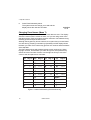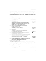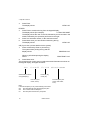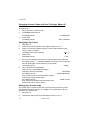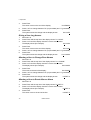
1
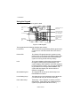
USER GUIDE
808
HARDWIRED CONTROL
PANEL
Scantronic
Leading the way in security
Contents
1. Introduction .............................
The 808 System ............................
Using the Keypad ..........................
About This Guide ...........................
2. Everyday Operation .................
Setting the System ........................
3
3
4
5
6
6
Timed Setting ................................. 6
Final Exit ........................................ 7
Exit Terminate Button ..................... 7
Instant Set ...................................... 7
Keyswitch Setting ........................... 8
If the System Will Not Set .............. 8
Unsetting the System .................... 9
Using the Keypad ........................... 9
3. After an Alarm ........................
Fire Alarm ....................................
Disarming the System .................
Resetting the System ..................
10
10
10
10
5. Supervisor .............................. 19
Introduction .................................. 19
Access codes ............................... 19
Duress Code ................................ 19
Restricting users to Arm Only ...... 19
Changing Access Codes and User
Privileges (Menu 8) ................. 20
Changing User Codes .................. 20
Setting Up a Duress Code ........... 20
Giving a User Arm Only Access ... 21
Allowing a User to Omit Zones ..... 21
Giving a User Log Access ............ 22
Allowing a User to Change Zone
Names .................................... 22
Allowing a User to Reset After an
Alarm ...................................... 22
Allowing a User to Change the Time
and Date. ................................ 23
User Records ............................... 23
Customer Reset ........................... 11
Engineer Reset ............................ 11
Remote Reset .............................. 11
4. Special Functions .................. 12
Introduction .................................. 12
Omitting Zones (Menu + Level) ... 12
Omitting 24 Hour Zones (Menu 2) 13
Turning the Chime On/Off
(Menu 3) ................................. 13
Testing the System (Menu 4) ....... 14
Walk Test ..................................... 14
Bell Test ....................................... 15
Setting the Time and Date
(Menu 6) ................................. 15
Changing Zone Names (Menu 7) . 16
Using the Log (Menu 9) ............... 17
808 Hardwired Control Panel User Guide.
© Scantronic Ltd. 1997
Every effort has been made to ensure that the contents of this book are correct. However, neither the authors
nor Scantronic accept any liability for loss or damage caused or alleged to be caused directly or indirectly by
this book. The contents of this book are subject to change without notice.
Printed and published in the U.K.
1. Introduction
The 808 System
The 808 system comprises an end station, one or more keypads, and various
detectors.
The end station is a steel box that houses the main components, power
supply and stand-by battery. The end station is normally fitted out of sight in a
safe place (for example under the stairs).
The detectors are installed at various places, or zones, around the premises.
If something triggers a detector it signals back to the end station. How the
end station reacts depends on whether the system is set or unset.
If the system is set it will raise an alarm whenever one of the detectors is
triggered. The alarm might be a bell or strobe on the outside of your
premises, or it might be a silent signal over the telephone line to a central
monitoring station. When unset the system does not raise an alarm if a
detector is triggered.
The 808 provides four different setting Levels, labelled A, B, C an D. Each
Level may protect a different area of your premises. The system raises an
alarm when a detector belonging to a set Level is triggered. If a detector
belonging to an unset Level is triggered then the system will not raise an
alarm. The Installer programs the Levels during installation. Ask your Installer
to tell you which zone is allocated to each Level.
Your premises may be fitted with 24 hour zones and panic alarm zones. If
these zones are triggered the system will raise an alarm whether or not any
Level is set.
The keypad is used to operate the system. From the keypad you can set and
unset the system, read the event log, and make minor changes to the way
the system operates.
You must enter an access code before the system will accept commands
from the keypad. The system can store up to 8 different access codes,
providing secure access for 8 users. One access code is reserved for the
system supervisor, who can change the access codes of all the other users.
None of the other users can change the access code for the supervisor.
496235 Issue 1
3
1. Introduction
Using the Keypad
Figure 1 below shows the keypad in detail.
Levels LEDs (Set or
Unset)
8 characterLiquid Crystal
Display (LCD)
Power
Optional programmable
panic alarm keys. Press
keys 1 and 3 together
Level setting keys
Optional programmable
control function keys.
Press keys 7 and 9
together.
Keyboard with
backlit soft rubber
keys
Menu and Enter keys
Figure 1. 808 Keypad
The keypad has the following displays and controls:
Level LEDs
Each Level LED (Light Emitting Diode) glows when
a Level is set. The LED is dark when the Level is
unset.
Power LED
The Power LED glows when the system is using
mains power. If the Power LED flashes slowly then
the mains power has been disconnected and the
system is running off the stand-by battery.
LCD
The system displays information and instructions
through the LCD (Liquid Crystal Display). The
system displays which detector has been triggered
by giving its zone number. You can use the keypad
to give detectors meaningful zone names. The
system will then display the names when the
detector is triggered.
Illuminated keypad
The keypad can be set up so that the keys are
illuminated from behind.
Level Setting Keys
Use these keys to set individual Levels. (Note that
you will have to use your access code first.)
Panic Alarm Keys
Press keys 1 and 3 together to raise a personal
attack alarm. (Check with your Installer that your
system is programmed with this function.)
4
496235 Issue 1
1. Introduction
Control Function Keys
Your system may be fitted to control other devices
such external lighting. Press keys 7 and 9 together
to activate or deactivate the device. (Check with
your Installer that your system is programmed with
this function.)
Menu and Enter
The Menu key lets you start programming the
system so that you can change some of its functions (see 5. Supervisor). The Enter key tells the
system that you have finished entering an access
code (or other command).
About This Guide
The rest of this guide tells you how to use the system in more detail:
2. Everyday Operation
Describes how to set and unset the system.
3. After an Alarm
Tells you how to switch off the sounders after an
alarm, how to see what caused the alarm, and how
to reset the system so that it can be used again.
4. Special Functions
Tells you how to use the more advanced features
of the system.
5. Supervisor
Tells you how to control who has access to the
system, and how to limit what they can do. This
section is intended for someone who is responsible
for the whole alarm system.
496235 Issue 1
5
2. Everyday Operation
The 808 provides several different ways for setting the system. All methods
(except using a Keyswitch) require entering your access code at the keypad. The Keyswitch method uses a key in a special switch fitted outside your
premises. "Setting the System" below describes each method. Ask your
Installer to provide the method that suits your site best.
During installation the Installer programs the system to create an exit route
for your premises. When setting the system you must follow this route to
leave the premises. Similarly you must follow a specified entry route when
going into the premises in order to unset the system. If you stray from these
routes you may cause a false alarm.
Note: The system may be programmed so that your access code can set some
Levels but not others. See "5. Supervisor".
Setting the System
Timed Setting
With Timed Setting the system sets after a programmed exit time. Ask your
Installer to make sure the exit time is long enough for you to leave the
premises and close the final door. The exit time starts when you finish entering the set command at the keypad. During the exit time the keypads give a
continuous exit tone to warn you that the timer is running. If you hear an
interrupted tone from the keypad when you try to set the system then one of
the doors on the exit route is open. Make sure that they are all closed.
1. Close all doors and windows.
2. Key in your access code at the keypad.
3. Press the appropriate Level button.
The keypad starts the continuous exit tone, the
Level LED flashes, and the display shows:
READY LEAVE
4.
Leave via the designated exit route. Close the final door.
At the end of the exit time the system sets, and stops the exit tone. The
Level LED glows to show which Level is set.
You can also set the system by entering your access code and pressing
Enter. The system will set to the highest Level that the Installer has programmed.
If you do not close the final door before the end of the exit time then the
system gives an internal alarm and does not set. Go back to the keypad and
unset the system, see "3. After an Alarm".
6
496235 Issue 1
2. Everyday Operation
Note: Some Levels on your system may be programmed for Silent Set. When
setting these Levels the system does not give any tones from the keypads.
Final Exit
With Final Exit setting the system sets when you close the last door. There is
no fixed exit time.
1. Close all doors and windows.
2. Key in your access code at the keypad.
3. Press the appropriate Level button.
The keypad starts the continuous exit tone, the
Level LED flashes, and the display shows:
READY LEAVE
4.
Leave via the designated exit route and close the final door.
The system sets and stops the exit tone seven seconds after you close
the final door. The Level LED glows to show which Level is set.
Exit Terminate Button
In Exit Terminate Button setting the system completes setting after you press
a button mounted outside the premises by the final door.
1. Close all doors and windows.
2. Key in your access code at the keypad.
3. Press the appropriate Level button.
The keypad starts the continuous exit tone, the
Level LED flashes, and the display shows:
READY LEAVE
4.
5.
Leave via the designated exit route. Close the final door.
Press the exit terminate button.
The exit tone stops and the system sets.
Note: The Installer may have programmed your system to set after a fixed time even
if you do not press the exit terminate button. This is to make sure your
premises are protected even if you forget to press the exit terminate button.
Ask your Installer how your system is set up.
Instant Set
With Instant Setting the system sets as soon as you complete entering the
set command from the keypad.
1. Close all doors and windows.
2. Key in your access code at the keypad.
3. Press the appropriate Level button.
The system sets immediately. The Level LED glows to show which
Level is set.
496235 Issue 1
7
2. Everyday Operation
Keyswitch Setting
1.
2.
3.
Close all doors and windows.
Turn the keyswitch.
Leave the premises and close the final door.
The system sets.
Note that some keyswitches have two setting positions: "Full" and "Part". Ask
your Installer which parts of your premises are covered by each of these
positions.
If the System Will Not Set
If the end station has detected a problem with one or more of the detectors
then the keypad will give a "beep" and show either a fault or a trouble
message.
A fault message means that one of the detectors is being triggered (for
example, a door or window is open). The system will not set until you
have cleared all the faults.
A trouble message means that one of the detectors may be reporting that it
has a technical problem. The system can still set when there is a trouble
message, but you should report the message to you Installer.
For both types of message the keypad display can show you which zones
have problems.
For faults the displays shows (for example):
SET STOP
02 FLTS
The system cannot finish setting because two detectors are being
triggered.
1.
Press the A or B keys.
The display shows each zone that is being triggered.
2.
Press A or B repeatedly until you have seen all the faults. Note down
the zones reported.
Go to each zone and find out what is triggering the detector. If possible
remedy the fault.
Go back to the keypad, press Menu, and try to set the system again.
3.
4.
For trouble messages the displays shows
(for example)
The system can still set.
8
496235 Issue 1
Z IN TRB
1 FLT
2. Everyday Operation
1.
Press the A or B keys.
The display shows the zone that is reporting trouble.
2.
Press A or B repeatedly until you have seen all the trouble messages.
Note down the zones reported.
Press Enter.
The display shows:
READY LEAVE
3.
4.
Leave via the designated exit route. Close the final door.
Zones giving trouble reports do not affect the system security.
Your alarm system will still work correctly. Contact your alarm
company to let them check the system.
Unsetting the System
If You Have a Keyswitch
Turn the keyswitch to OFF. The system unsets immediately.
Using the Keypad
They system has a programmed entry time. Ask your Installer to make sure
the entry time is long enough for you to enter by the designated entry route,
get to the keypad and unset the system.
The entry time starts when you open the designated door on the entry route.
During the entry time the keypads give a "galloping" entry tone to warn you
that the timer is running. For the last 30 seconds of the entry time the galloping tone speeds up to warn you that the time is running out.
1. Enter the premises through the designated entry route and go to the
keypad.
As you enter the premises the system starts the entry timer and the
keypad gives the entry tone (a "galloping" tone).
2.
Key in your access code at the keypad and press Enter.
The entry tone stops. The system is now unset.
WARNING: If you enter the premises and the keypad is
silent then there may be an intruder.
496235 Issue 1
9
3. After an Alarm
When your system raises an alarm you must disarm it in order to switch off
the sounders and strobes. The system keeps a record of which zone(s)
triggered the alarms, and shows the zone on the keypad display. Once you
have disarmed the system, the system must be reset before you can start
using it again.
Fire Alarm
The system gives a fire alarm by sounding a warbling tone from the keypads
and inernal alarm sounder. The keypad shows the message:
* FIRE *
LEAVE
1.
2.
Evacuate the premises and call the Fire Brigade. Do not attempt to
unset the alarm.
When the premises are safe, follow the instructions below.
Disarming the System
1.
2.
Go to the keypad via the entry route.
Key-in your access code and press Enter.
The sounders go quiet and the display shows:
followed by the cause of the alarm
(for example):
3.
SYS DIS
RST REQ
ALARM
DINE RM
Establish the cause of the alarm and then carry on and reset the system.
Resetting the System
The 808 has three different methods for resetting:
Customer Reset. You can reset the system yourself from the keypad.
Engineer Reset. Someone from your alarm company must visit the
premises to reset the system from the keypad.
Remote Reset. Your alarm company will give you instructions over the
phone and a special code so that you can reset the system from the
keypad.
Ask your alarm company what type of reset your system has.
10
496235 Issue 1
3. After an Alarm
Customer Reset
1.
Key-in your access code and press Enter.
The keypad displays:
followed by the time.
SYSTEM RST OK
You can now use your system as normal.
If the keypad displays (for example):
CANT RST
02 FLTS
then a 24 hour detector may be operating,
or the anti tamper protection on your system may
be damaged.
1.
2.
Press A or B to see any more faults.
Contact your alarm company.
Engineer Reset
1.
2.
Key-in your access code and press Enter.
The keypad displays:
CALL ENGINEER
Call your alarm company and ask them to come and reset the system.
Remote Reset
If your system uses remote reset, the display shows the words "CTRL CDE"
followed by a four digit code.
1. Write down the four digits shown after the "Control Code".
2. Contact your alarm company central station.
The central station will ask a few questions to make sure you are who
you say you are. They will then ask for the circumstances of the alarm.
If they do not need to send an Engineer to check the system they will
give you a "Reset Code".
3.
4.
Key in the Reset Code on the keypad and press Enter.
Key in your access code and press Enter.
The display shows:
SYS NOW
RST
Note: Your alarm company may use "RedCare Reset". Carry out steps 1 and 2 as
described above. Once the central station have confirmed your identity, they
will reset your system by sending signals over the telephone line. You must
then key in your access code and press Enter .
496235 Issue 1
11
4. Special Functions
Introduction
Some users may be allowed to perform a number of other functions, apart
from setting and unsetting the system. These functions are:
Setting the system so that some zones are bypassed or omitted.
Turning the chime function on or off.
Testing the zones and sounders.
Setting the time and date on the system's internal clock.
Changing zone names.
Reading the system log.
To use these functions you must key in your access code and then press
Menu followed by a number. In addition, the alarm system supervisor (see
section 5) must program the system to allow each user access to individual
menu number. The rest of this section assumes that the user has access to
the functions described.
Omitting Zones (Menu + Level)
Your system may be programmed so that you can omit individual zones
when setting the system. This function is useful, for example, if you have to
by pass a detector while decorating. Ask your Installer which zones can be
omitted. Note that omission is not permanent. You must omit the zone every
time you set the system.
To set with a zone omitted:
1. Key in your access code.
2. Press Menu.
The display shows:
MENU NO
OR LEVEL
3.
4.
5.
6.
12
Press the Level key for the Level you wish to set.
The display shows:
Press Enter.
The display shows (for example):
OMIT ZONES
HALL
OMIT NO
Press A or B until the display shows the zone that you want to omit.
Note that some zones may not be programmed for omission.
Press C or D until the display shows the words "OMIT YES".
496235 Issue 1
4. Special Functions
7.
Press Enter.
The displays shows:
READY LEAVE
The system carries on to set as normal. The system will not raise an
alarm if the omitted zone is triggered. Note that the next time you set the
Level the system will treat the zone as normal; omission only lasts for
one setting/unsetting cycle.
Omitting 24 Hour Zones (Menu 2)
If your system is fitted with 24 hour detector zones, you may be able to omit
them if necessary. For example, your premises may have a fire door that you
occasionally open. Ask your Installer if this is possible.
If your system is programmed to allow you to omit a 24 hour zone, then:
1. Key in your access code.
2. Press Menu followed by 2.
The display shows:
2-OMIT 24 HR ZO
3.
4.
5.
6.
Press Enter.
The displays shows (for example):
FIRE DR
OMIT NO
Press A or B until the display shows the 24 hour
zone that you want to omit. Note that some zones
may not be programmed for omission.
Press C or D until the display shows the words "OMIT YES".
Press Enter.
The displays shows:
2-OMIT 24 HR ZO
The system will not raise an alarm if the omitted zone is triggered.
To reinstate a 24 hour zone: repeat steps 1 to 6 but at step 5 press C or D to
make sure the display shows "UN-OMIT".
Turning the Chime On/Off (Menu 3)
Your system may be programmed so that a chime tone sounds whenever
certain doors are opened. If you want to turn this feature on or off:
1. Key in your access code and press Menu followed by 3.
The display shows:
3-SYSTEM OPTNS.
2.
Press Enter.
The system displays the current state of the
chime function:
496235 Issue 1
CHIME D
13
4. Special Functions
3.
Press C or D to change between D (disabled) and E (enabled).
The display shows:
CHIME E
4.
Press Enter to save the change.
Testing the System (Menu 4)
You can set the system so that it will allow you to walk round the premises
and test each of the detectors (a walk test). At the same time you can also
test the external bell and strobe. Choose a time when the premises are
empty to carry out the test, otherwise people may trigger any movement
detectors before you do, and confuse the results of the test.
If any detector fails the test then call your alarm company and ask them to
check the system.
Note: If your system is fitted with 24 hour or personal attack detectors, you cannot
walk test them. If you wish to test them call your alarm company.
Walk Test
1.
2.
3.
4.
5.
Key in your access code.
Press Menu followed by 4.
The display shows:
4-TEST OPTNS
Press Enter.
The display shows:
WALK TEST
Press Enter.
The top line of the display shows the total
number of detectors to test, while the
bottom line shows the zone number of each
detector to be tested, for example:
Walk round your premises and trigger each detector. Note: do not
trigger any 24 hour or personal attack detectors (they will not appear in
the list of detectors to be tested). If you do trigger a 24 hour or personal
attack detector the system will raise an alarm.
As you trigger a detector the internal sounder gives a tone, and the
zone number disappears from the display.
When all detectors shown on the list have been
tested successfully the display shows:
Note: You can abandon the test at any time by pressing Menu.
14
07 TO TEST
01 02 >
496235 Issue 1
WLK TEST
COMPLETE
4. Special Functions
Bell Test
1.
2.
3.
4.
5.
Key in your access code.
Press Menu followed by 4.
The display shows:
4-TEST OPTNS
Press Enter.
The display shows:
WALK TEST
Press B
The display shows:
BELL TST
Press Enter.
The system turns the external sounder, strobe, and internal sounder(s)
on for five seconds each, one after the other. While the test is running
the display shows the device that should be operating. At the end of the
test the display shows the date and time.
Note: You can abandon the test at any time by pressing Menu.
Setting the Time and Date (Menu 6)
The end station contains an internal clock/calendar that runs as long as there
is power present (mains or stand-by battery). The system uses this clock to
mark the time and date on the system log. If the power supply fails for any
reason, and the stand-by battery is low, then the system loses track of the
correct time and date. You may also need to change the time if you live in an
area that uses summer/winter time.
To set the time and date:
1. Key in your access code.
2. Press Menu followed by 6.
The display shows:
6-SET TI/DA
3.
4.
5.
Press Enter.
The display shows (for example):
Note that one of the characters has a bar
underneath it (called the cursor).
26MAR96
Press C or D until the cursor is under the item that
you want to change.
The display shows (for example):
12:18
Press A or B to change the numbers to the value
you want.
The display shows (for example):
13:18
496235 Issue 1
15
4. Special Functions
6.
Press Enter followed by Menu.
The system saves the change you made and the
display shows the new time and date:
26MAR96
13:18
Changing Zone Names (Menu 7)
The system allows you to store names for each detector zone. The display
shows the names when it raises an alarm, or if you are using some of the
special functions. Each zone name can be a maximum of 8 characters long,
including spaces and punctuation marks.
Although the keypad only shows numbers, the system lets you enter letters
one at a time by pressing a number key repeatedly until the display shows
the letter you want. Each number key gives its own number and three letters
of the alphabet.
The figure below shows which letters belong to each number key. When
keying in a name, find the letter you want on Figure 2, then press the key
shown the correct number of times. Use the right arrow key to move the
cursor to the next space for a new letter.
For Key in For Key in For Key in
For
Key in
1
1
A
11
K
444
U
7777
2
2
B
111
L
4444
V
88
3
3
C
1111
M
55
W
888
4
4
D
22
N
555
X
8888
5
5
E
222
O
5555
Y
99
6
6
F
2222
P
66
Z
999
7
7
G
33
Q
666
Space
9999
8
8
H
333
R
6666
'
00
9
9
I
3333
S
77
(
000
0
0
J
44
T
777
)
0000
Figure 2. Letters Generated by Each Number Key
16
496235 Issue 1
4. Special Functions
If you make a mistake, press C or D to move the cursor over the letter you
want to change, and key in the new letter. If you want to delete a name
completely, press D repeatedly to move the cursor under the extreme left
hand character of the name. Press D again. The display clears the old name.
To change a zone name:
1. Key in your access code.
2. Press Menu followed by 7.
The display shows:
7-ZONE NAMES
3.
Press Enter.
The display shows:
Z01-NAME
ZONE 01
The top line of the display shows the zone number.
The bottom line shows the current zone name. Note
that the cursor is under the zone number.
4.
5.
6.
7.
8.
Press A or B until the display shows the zone
number you wish to name.
The display shows (for example):
Press Enter.
The display cursor moves to the first character
of the zone name (for example):
Key in the zone name as described at the beginning
of this subsection (see Figure 2).
Press Enter when you have completed the zone name.
The system saves the new name and moves the
cursor back to the zone number, for example:
Z03-NAME
ZONE 03
ZONE 03
Z03-NAME
LOUNGE
EITHER repeat steps 4 to 7 for all the other zones you
want to name, OR press Menu twice to stop.
Using the Log (Menu 9)
The system keeps a log of the last 250 events. You can examine this log
from the keypad. If you have a printer attached to your system you can also
print the log. To use the log:
1. Key in your access code.
2. Press Menu followed by 9.
The display shows:
9-LOG FUNCTS
496235 Issue 1
17
4. Special Functions
3.
Press Enter.
The display shows:
VIEW LOG
EITHER:
4. Press Enter to examine the log from the keypad display.
The display shows (for example):
U1-Z02- NW NAME
The display shows the user on the left, followed by a zone number in the
middle, followed by the operation performed on the right.
5.
6.
Press A to see earlier events, or B to see later events.
Press Menu when you have finished examining the log.
The display shows:
OR (if you have a printer attached to the system)
7. Press A followed by Enter to print the log.
The system starts printing the log and the
display shows:
When log is finished printing the display
shows:
VIEW LOG
PRINTING LOG
PRINT EVNT LOG
8. Press Menu twice.
The printed record of each event contains the same information as shown on
the keypad display, arranged as follows:
001:
13:09:55
Audit Number (not shown
on keypad displays)
27/3/96
Event Date (day,
month, year)
Event Time (hour,
minute, second)
Event Description (user
number, area number,
event)
Notes:
In the event description you may see the following user numbers:
U00
when the installer has been programming the system
U09
when a remote reset has taken place
U11
when the system has been set by a keyswitch.
18
U02:A02:UNSET
496235 Issue 1
5. Supervisor
Introduction
This section describes the facilities available to the alarm system supervisor.
To be a supervisor you must use a special access code (see below). The
supervisor can allow or deny access to all the special functions described in
section 4. In addition, the supervisor can change access codes, set up
Duress Codes, and restrict users so that they can set the system but not
unset it.
Access codes
The 808 can store up to 8 different user access codes. For security you
should give one code to each person who has responsibility for setting and
unsetting the system. Do not allow users to share codes.
Every time someone enters an access code on the keypad the system
records the event in its log. To distinguish all the users and keep their access
codes hidden, the log shows each user as a number, for example "User 02",
"User 03" and so on.
The supervisor's access code is always "User 01". User 01 has access to
menu 8, which is used to change access codes and other user privileges. No
other user has access to menu 8.
Duress Code
If your system is connected to a central monitoring station, you may want to
give some of the users a Duress Code. If a user enters the Duress Code
while the system is set, then the end station unsets the system, but at the
same time sends a silent alarm call to the central monitoring station. This
facility is designed for times when a user is being forced to unset the alarm
system by an intruder.
Note that a Duress Code occupies one user number. The duress code
cannot operate any of the special functions described in "4. Special Functions".
Restricting users to Arm Only
Some of the people who enter your premises may not need full access to all
the alarm system functions. You can give these users Arm Only status. This
means that the user can set the system, but not unset it or use any special
functions. This facility is designed for people like cleaners who may need to
secure your premises after the daytime occupants have left.
496235 Issue 1
19
5. Supervisor
Changing Access Codes and User Privileges (Menu 8)
You must start from menu 8 for all the facilities described in this section.
To start menu 8:
1. Key in the User 01 access code.
2. Press Menu followed by 8.
The display shows:
8-USER INFO
3.
Press Enter.
The display shows:
EDIT USR INFO
Changing User Codes
1.
2.
3.
Start menu 8.
Press Enter until the top line of the display shows "U1-C****".
Press A or B until the display shows the user number whose access
code you wish to change.
The display shows (for example):
U2-C****
4.
Press Enter.
The display shows:
5.
U2-C_
Key in the four digits of the new user code and press Enter. Note that
the display shows " * " characters instead of numbers. This is to prevent
anyone reading the access code over your shoulder.
The display shows:
CONF_
6.
Key in the same four digits again.
After you key in the last digit the display
changes to show (for example):
If the display shows:
then you did not key in the confirmation correctly.
Press Menu and go back to step 4.
If the display shows:
then another user already has that access code.
Press Menu and go back to step 4.
U2-DURSN
CODE MISMATCH
CODE IN USE
Setting Up a Duress Code
The system does not allow a user with a duress code access to any of the
special functions listed in section 4. In addition, the system will not let you
give User 01 a duress code.
1. Start menu 8.
2. Press Enter until the top line of the display shows "U1-C****".
20
496235 Issue 1
5. Supervisor
3.
Press A or B until the display shows the user number you wish to use
for the duress code.
The display shows (for example):
U7-CNOCO
4.
Press Enter.
The display shows:
5.
6.
U7C_
Key in the duress code and press Enter.
The display shows:
Key in the duress code again.
When you key the last digit of the duress code
the display shows:
CONF_
U7-DURSN
7.
Press C or D to change from "N" (disabled) to "E" (enabled).
The display shows:
U7-DURSE
8.
Press Enter.
The system saves the change and the display shows:
U7-ARMON
9. Press Menu to finish programming.
If you want to remove a duress code from a user number, follow steps 1 to 8
again but at step 7 press C or D to change the display to "DURSD".
Giving a User Arm Only Access
1.
2.
3.
Start menu 8.
Press Enter until the top line of the display shows "U1-ARMON".
Press A or B until the display shows the correct user number.
The display shows (for example):
U2-ARMON
4.
Press Enter.
The cursor moves to end of the display:
5.
6.
U2-ARMON
Press C or D to change between "N" (full use) and "Y" (arm only).
Press Enter.
The system saves the change and the display shows:
U2-OMITN
Allowing a User to Omit Zones
1.
2.
3.
Start menu 8.
Press Enter until the top line of the display shows "U1-OMITN".
Press A or B until the display shows the correct user number.
The display shows (for example):
U2-OMITN
496235 Issue 1
21
5. Supervisor
4.
5.
6.
Press Enter.
The cursor moves to the end of the display:
U2-ARMON
Press C or D to change between "N" (not permitted) and "Y" (permitted).
Press Enter.
The system saves the change and the display shows:
U2-LOGN
Giving a User Log Access
1.
2.
3.
Start menu 8.
Press Enter until the top line of the display shows "U1-LOGN".
Press A or B until the display shows the correct user number.
The display shows (for example):
U2-LOGN
4.
Press Enter.
The cursor moves to the end of the display:
5.
6.
U2-LOGN
Press C or D to change between "N" (not permitted) and "Y" (permitted).
Press Enter.
The system saves the change and the display shows:
U2- CHANN
Allowing a User to Change Zone Names
1.
2.
3.
Start menu 8.
Press Enter until the top line of the display shows "U1- CHANN".
Press A or B until the display shows the correct user number.
The display shows (for example):
U2-CHANN
4.
Press Enter.
The moves to the end of the display:
5.
6.
U2-CHANN
Press C or D to change between "N" (not permitted) and "Y" (permitted).
Press Enter.
The system saves the change and the display shows:
U2-RST N
Allowing a User to Reset After an Alarm
1.
2.
3.
Start menu 8.
Press Enter until the top line of the display shows "U1-RST N".
Press A or B until the display shows the correct user number.
The display shows (for example):
U2-RST N
4.
Press Enter.
The cursor move to the end of the line:
22
496235 Issue 1
U2-RST N
5. Supervisor
5.
6.
Press C or D to change between "N" (not permitted) and "Y" (permitted).
Press Enter.
The system saves the change and the
top line of the display shows:
U2-D-T Y
Allowing a User to Change the Time and Date.
1.
2.
3.
Start menu 8.
Press Enter until the top line of the display shows "U1-D-T Y".
Press A or B until the display shows the correct user number.
The display shows (for example):
U2-D-T N
4.
Press Enter.
The cursor moves to the end of the line:
5.
6.
U2-D-T N
Press C or D to change between "N" (not permitted) and "Y" (permitted).
Press Enter.
The system saves the change and the display
shows (for example):
U3-C****
User Records
Use the table on the inside of the back cover to keep a record of the users
who have access to your alarm system. DO NOT write down any access
codes.
496235 Issue 1
23
24
496235 Issue 1
USER No. NAME
USER 01
USER 02
USER 03
USER 04
USER 05
USER 06
496235 Issue 1
USER 07
USER 08
DURESS
ARM OMIT LOG
ZONE
ONLY ZONES ACCESS NAMES
RESET
TIME &
DATE
25
Installer name:
Day Tel:
Night Tel:
Manufactured in the UK by Scantronic Ltd.
Part No. 496235 Issue 1