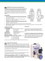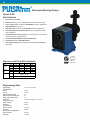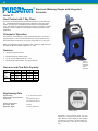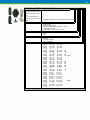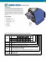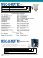
1
Product List Effective 01/14/13 Metering Pumps and Control Systems 2 TABLE OF CONTENTS Important Information When Placing An Order Feature Selection Guide Model Selection Guide 3 4 5-9 PULSAtron - Electronic Metering Pumps Series MP Series E Plus Series HV Series E Series E-DC Series A Plus Series T7 Series C Plus Series C Series ET 10-11 12-13 14-15 16-17 18-19 20-21 22-23 24-25 26-27 28-29 Electronic Metering Pump Accessories KOPkits Suction/Discharge Valves Parts 30-31 32 33-35 OMNI - Mechanical Diaphragm Pumps Model Selection Accessories and KOPkits 36-38 39 Chem-Tech Pumps – Peristaltic Metering Pumps Series XP Series XPV Series XP and XPV Parts Mechanical Diaphragm Pumps Prime Performance Series 100, 100D, 150, 150D, 200 and Parts Series 250 and Parts 40 41 42 43 44-47 48 Mec-O-Matic Pumps – Diaphragm Metering Pumps Stingray 100, 200 and Parts T-2000 Peristaltic Metering Pumps Dolphin Series and Related Parts VSP Series and Parts 2400T, 2400T Plus, 2400T-DC and Parts 49-50 50 51 52 53 Policies and Procedures Terms and Conditions 54-55 56 DUE TO CONTINUOUS IMPROVEMENT OF OUR PRODUCTS, WE RESERVE THE RIGHT 3 IMPORTANT INFORMATION WHEN PLACING AN ORDER 1) Fax, mail or telephone orders directly to the Customer Service Department: Pulsafeeder Incorporated—A Unit of IDEX Corporation Standard Product Operations Main Office & Manufacturing Facility 27101 Airport Road, Punta Gorda, Florida, USA 33982-2462 E-Mail: [email protected] Telephone: 800-333-6677 or 941-575-3800 Fax: 800-456-4085 or 941-575-4085 www.pulsatron.com 2) Please have the following information available when placing an order: Account Name Billing Zip Code Purchase Order Number Ship To Address Special Tags or Marks (if needed) Item(s) Being Ordered Quantity of Each Item 3) Orders are immediately entered into the computer upon receipt. Our ability to change in house orders is limited. Please be certain your orders are complete when placed. 4) For assistance or to order a “special” pump model not available in the price schedule, please contact our Technical Support Department. 5) Orders are assigned standard lead times based on the size of the order and the time required to manufacture the particular products. Requests to expedite orders may be routed through our Customer Service Department. 6) Repairs and returns are coordinated through our Customer Service Department. All orders returned must have factory authorization and are subject to a 25% restocking charge for standard product. 7) Other Locations: PULSAFEEDER (Knight UK Limited) Highland Industrial Estate, Unit 12 & 13 Edison Rd Eastbourne, East Sussex England, BN23 6PT Tel: +44 1323514855 Fax: +44 1323514828 Far East (Office Only) Room 3502-3504, Zhao Feng Plaza No. 1027 Changning Rd Shanghai 200050, China Tel: 86-2163906367 Fax: 86-2163863338 Latin America (Office Only) Av Ejercito Nacional #404 Piso 8, Officinas 801-802 Col. Chapultepec Morales Mexico, DF, CP 11560 Mexico Tel: 52-555-255-1357 Fax: 52-555-255-1356 IDEX India Private Ltd. Sunteck Center, 3rd Floor 37-40 Subhash Road, Vile Parle East Mumbai-400 057, India Tel: 91-22-66435500 Fax: 91-22-66780055 Prices are subject to change without notice and are effective when order is accepted and acknowledged at point of shipment. When ordering, specify your P.O. number, model number, quantity, price, shipping and/or billing address and order date. Standard terms are NET 30 days from date of invoice for approved accounts on open account. WE ACCEPT VISA AND MASTERCARD. ONE PERCENT DISCOUNT AVAILABLE FOR PAYMENT WITHIN 10 DAYS OF INVOICE DATE FOR ACCOUNTS THAT ARE CURRENT. PAYMENT BY CREDIT CARD WILL NOT RECEIVE AN ADDITIONAL DISCOUNT. All prices are F.O.B. Punta Gorda, FL or factory warehouse location. Custom product sales are final. Charges for export documentation apply. Expediting fees may apply. Fees for changes to or cancellation of orders may apply. Minimum factory order of $50. Possession of price schedule does not guarantee right to purchase direct from factory. DUE TO CONTINUOUS IMPROVEMENT OF OUR PRODUCTS, WE RESERVE THE RIGHT TO UPDATE THE INFORMATION CONTAINED IN THIS CATALOG WITHOUT NOTICE. 4 Feature Selection Guide Pulsafeeder offers one of the most flexible electronic metering pumps in the world. The product can be configured to meet a large variety of applications and needs. The next few pages will guide you in structuring a complete and correct model number. The first step in selecting the right model for your application is to select the correct Series. Each Series offers a variety of features that distinguish it from other Series. Within each Series are selections of models that offer different flow/ pressure envelopes to choose from. The following descriptions will help you understand the different features and then the chart at the bottom of the page will let you select the appropriate models that have the features you need. S = S t a nda rd F e a t ure s BAR 1.3 to 21 2.0 to 21 5.6 to 17 1.3 to 21 7 to 10 3.3 to 17 7 5.6 5.6 1.3 to 17 O = O pt io na l F e a t ure s S S O S S S S Timed Sequences Programmable Timer PSIG 20 to 300 30 to 300 80 to 100 20 to 300 100 to 150 50 to 250 100 80 80 20 to 250 Alarm Signals LPH 0.50 to 0.50 to 1.9 to 37.9 0.50 to 0.90 to 7.0 0.90 to 7.6 1.9 to 7.6 0.90 to 4.7 0.90 to 4.7 0.80 to Turn Dow n Ratio 1000:1 S 100:1 O 100:1 O 100:1 100:1 100:1 10:1 100:1 10:1 100:1 Signal/Power Relay Series GPH 0.13 to 21 MP 0.13 to 25 E Plus 0.50 to 10 HV 0.13 to 25 E 0.25 to 1.85 E-DC 0.25 to 2 A Plus 0.50 to 2 T7 C Plus 0.25 to 1.25 0.25 to 1.25 C 0.21 to 2 ET Pressure Digital Display Flow Capacity Touch Pad Stop Function Touch Pad Digital Display Signal Relay Pow er Relay Alarm Display Timed Sequences Programmable Timer Hall Effect Conductivity Control Bleed Relay Timer Control Flow Control External Pace And Stop External Pace Or Stop Function External Pace / Water Meter 20-4 mA 20-4mA Control the pump stroke frequence based on a current input signal from an external device. At 4mA input, the pump w ill not stroke. At 20mA input, the pump w ill stroke 100% Same as 4-20 except that at 20mA input, the pump w ill not stroke and at 4mA input, the pump strokes at 100%. Allow s the pump stroke to be controlled by an external dry contact closure, such as is provided by a Water Meter. For each closure, the pump w ill stroke one time. Some models provide the ability to multiply or divide the pulses. A dry contact input that w ill stop the pump on closure and allow the pump to operate w hen open. Electronic 'touch pad' control w ith internationally recognized symbols. Pump parameters are displayed on an LCD or LED type display. Provides a 24V DC signal output from the pump based on user specified conditions. Provides AC pow er output from the pump based on user specified conditions. Flashing display or LED indicator that w ill display an alarm condition on the front panel of the pump. Ability to pre-program operation for repetitive metering. Timer that can be programmed w ith up to 8 on/off cycles per day during a 7-day w eek. Hall Effect Water Meter input. Includes a conductivity controller built into the pump. Separate relay used to control a solenoid that w ill "Bleed" a cooling tow er as part of a control system. User defined timer functions that control w hen the pump w ill operate. Used in Cooling Tow er control systems. Optional Flow Sw itch turns pump on w hen flow is active. 4-20 mA 4-20mA S O S O O S S 5 Model Selection Guide Once you have selected the appropriate Series, you must configure the model so that it is built with the features you desire. The Configuration Guide associated with each Series will present the most popular selections. Select one code from each category to build up a complete model string. To help you better understand the model string, in the following pages, we will explain what each of the digits represent and provide you some additional charts to help you select options not found in the Configuration Guides. Model Selection: The first four digits represent the Series and Flow/Pressure Selection. LB02 Series The first digit will always start with the letter ‘L’. LB02 Flow/Pressure Code Digits 3 & 4 represent the Flow/Pressure Code. All PULSAtron models begin with this letter. The second letter designates the Series (e.g. Series MP, Series E+, Series A+, etc.). Each series has a different set of features that are available in terms of control and flow/ pressure capacity. The next two digits represent the flow/pressure capacity of the pump. Series Code Designator Series MP M Series E Plus P Series HV V Series E E Series E-DC S Series D F Series A Plus B Series C Plus D Series C & T7 C Series ET T This code represents the specific flow/pressure rating for the model and can be found in the specification for each Series. LB02SA Electrical Controls Digits 5 & 6 represent the Controls and Electrical selections. These selections are explained for each model in the Configuration Guide. 6 Selection Guide cont’d. Selecting the Wet-End Code & Connection Type: Digits 7-10 in the string represent the wet-end code. It is the group of four digits set apart by the dash lines. LB02SA-PTC1 These four digits represent your wet-end code and connection type. The four digits in the wet-end code represent the Head Material, Seats & O-Rings, Ball Material and Connection type. Using the above example, the code breads down as follows: P - Head Material, including fittings. In this example, the P represents GFPPL. T - Seat & O-Ring Material. In this example, the T represents TFE. C - Types of Balls used in the valves. In this example, the C represents Ceramic. 1 - Connection type. In this example, the 1 represents tubing connections for 3/8” OD tubing. In the configuration Guide, we have listed the most popular Wet-End codes. If you don’t find the materials or connection selection to meet your needs, refer to the following selection guides to configure the proper Wet-End Code. Selecting the Wet-End Code: The wet-end code represents the materials of construction that will be in contact with the chemical you are pumping. It is critical that the materials selected are compatible. If you do not find the wet-end code to meet your application in the configuration guides, you can use the Wet-End Code Selection Guide to determine the correct Head Material, Seats & O-Rings and Balls. If you do not know what materials are compatible with the chemicals you are pumping, refer to the chemical compatibility chart below. We have identified the proper wet-end code for the chemicals in the list. If your chemical is not found in the list, please contact your chemical supplier or visit www.pulsatron.com for a complete listing. PULSAtron Wet-End Code Selection Guide H ead A K P V W & F it t ings = 316 Stainless Steel (All models except H8) = PVDF (Kynar) (Consult factory for J7, H8 models) = GFPPL (Polypropylene) = PVC (Poly Vinyl Chloride) (for models rated < 150 psi excluding K7, H7, H8) = PVC (for models > 150 psi and K7, H7, H8) Seat s H = T = V = CSPE TFE (not available with TFE ball over 150 psi) Viton (150 psi max.) Balls C H S T Ceramic Alloy C (Hastelloy) 316 Stainless Steel TFE (not available with TFE seat over 150 psi) = = = = _ _ CSPE is generic formulation of Hypalon, a registered trademark of E.I. DuPont Co. Viton is a registered trademark of E.I. DuPont Company. _ Chemical Compatibility Chart Chem ical ACETIC ACID, 5 - 10% ALUMINUM SULFATE AMMONIA, 10% BROMINE CALCIUM HYPOCHLORITE CITRIC ACID, 10 - 20% DEAE - Steamline Treatment ETHYLENE GLYCOL FERRIC CHLORIDE FERRIC SULFATE FLUOSILICIC ACID HYDROCHLORIC ACID, 0 - 37% HYDROCHLORIC ACID, 37 - 100% HYDROFLUOSILICIC ACID, 20% HYDROGEN PEROXIDE, 0 - 30% LACTIC ACID NITRIC ACID, 0 - 20% PHOSPHORIC ACID, 0 - 100% POTASSIUM CHLORIDE POTASSIUM PERMANGANATE SODIUM BI-CARBONATE SODIUM BI-SULFATE SODIUM BI-SULFITE SODIUM CARBONATE SODIUM HYDROXIDE, 0 - 50% SODIUM HYPOCHLORITE SODIUM NITRATE SODIUM SILICATE SODIUM SULFATE SODIUM SULFIDE SULFURIC ACID, 0 - 10% SULFURIC ACID, 10 - 75% SULFURIC ACID, 95 - 100% Liquid End Code PHC VHC PHC KTC VVC PHC ATS PTC VTC PTC PTT PTC KTT PTT VVC PTC PVC KTC PTC PTC PTC PTC PTC PTC PHC VVC PTC PHC PHC PHC PTC PTC KTC This is an abbreviated version using most common chemicals. Refer to the Chemical Resistance Guide (EMP-030) for a more detailed listing. 7 Selecting the Connection Code: Selecting the proper connection code is probably the most difficult part of choosing a PULSAtron pump. Because of the flexibility built into this product line to meet a large variety of applications, the connection codes are determined by alot more factors than just the size of the tubing. Connection code is probably the wrong name for this selection because you are selecting more than just the tubing size. This code also determines the type of valves used in the pump. The valve type is determined by factors such as flow rate of the pump, ball type selected and viscosity of the fluid you will be pumping. Flow Rate: The pump you select is rated to pump a certain number of gallons per hour (GPH). When selecting the connection code, please note the GPH limitations and select a connection that fits within the parameters of the pump model that you selected. Ball Type: If the material selected for the balls used in the check valves is TFE, you will probably need to use a spring-loaded connection. This is due to the fact that the weight of the balls will not allow them to seat properly without the spring. See the connection chart for a list of spring loaded connection types. Viscosity: Viscosity of the fluid you are pumping impacts the connection. The higher viscosity fluids (>3000 cps) require larger connection types and spring-loaded valves. Medium viscosity fluids (1000 to 3000 cps) can be pumped without the spring-loaded valves but you must use SS balls with these connections in order for the balls to seat properly in the valve. Degassing Head: The degassing head assembly is the solution to pumping gas producing chemicals such as hydrogen peroxide or high strength sodium hypochlorite. The unique de-gas valve system is designed to allow air to be vented from the pump head while minimizing the return fluid volume. It also prevents the pump from losing its prime due to gas build up. The degassing head will be available on all PULSAtron pumps with volumes <44GPD & pressures <150PSI. This feature is only available with the wet-end codes VVC9, VHC9, and VTC9. Connection Codes Code Connect Type 2 4 6 8 C G I L X 1 3 5 7 9 A B D E F H J K M R N P Q S T U V W Y Suction Discharge Spring .25" FNPT .25" FNPT Piping Piping .25" FNPT .25" FNPT Piping .25" FNPT .25" FNPT Piping .50" FNPT .50" FNPT .50" FNPT .50" FNPT Piping Piping .25" FNPT .25" FNPT Piping .50" MNPT .50" MNPT Piping .50" MNPT .50" MNPT .50" MNPT .50" MNPT Piping Tubing .25" x .38" .25" x .38" Tubing .38" x .50" .38" x .50" Tubing .50" x .75" .38" x .50" Tubing .50" x .75" .50" FNPT .25" x .38" .25" x .38" Tubing Tubing .38" x .50" .38" x .50" Tubing .50" x .75" .50" x .75" Tubing .25" x .38" .25" x .38" .38" x .50" .38" x .50" Tubing Tubing .38" x .50" .38" x .50" Tubing .25" x .38" .25" x .38" Tubing .25" x .38" .25" x .38" .50" x .75" .50" x .75" Tubing Metric Connections Piping G 1/2 A G 1/2 A Piping G 1/2 A G 1/2 A Tubing 4 x 10 mm 4 x 10 mm 4 x 6 mm 4 x 6 mm Tubing Tubing 10 x 14 mm 10 x 14 mm Tubing 6 x 10 mm 6 x 10 mm Tubing 6 x 10 mm 6 x 10 mm 6 x 10 mm 6 x 10 mm Tubing Tubing 12 x 19 mm 12 x 19 mm Tubing 10 x 16 mm 10 x 16 mm Tubing 6 x 12 mm 6 x 12 mm Yes Yes Yes Yes Yes Yes Yes Yes Yes Yes Yes GPH Flow GPH Flow Limitations-125 SPM Limitations-250 SPM 0-3.76 0 - 1.88 3.26-20 1.63 - 10 NA Up to 10 NA Up to 25 50 25 0-3.76 0 - 1.88 NA Up to 10 0-3.76 0 - 1.88 3.26-20 1.63 - 10 0-3.76 0 - 1.88 3.26-20 1.63 - 10 NA Up to 10 NA Up to 25 0-3.76 0 - 1.88 0-3.76 0 - 1.88 50 25 0-3.76 0 - 1.88 0-3.76 0 - 1.88 3.26-20 1.63 - 10 3.26-20 1.63 - 10 0-2.08 0 - 1.04 NA 1.88 - 25 (<50 psi) LPH Flow Limitations LPH Flow Limitations 12.3-75.7 6.15 - 37.85 0-14.2 0 - 7.10 0-14.2 0 - 7.10 0-7.88 0 - 3.94 12.3-75.7 6.15 - 37.85 > 37.86 > 18.93 0-14.2 0 - 7.10 0-14.2 0 - 7.10 >59.92 > 29.96 12.3-75.7 6.15 - 37.85 0-14.2 0 - 7.10 Viscosity Other Factors 1000 up to 3000 cps w/ SS balls 1000 up to 3000 cps w/ SS balls less than 10,000 cps less than 10,000 cps 1000 up to 3000 cps w/ SS balls 1000 up to 3000 cps w/ SS balls less than 10,000 cps 1000 up to 3000 cps w/ SS balls 1000 up to 3000 cps w/ SS balls 1000 up to 3000 cps w/ SS balls 1000 up to 3000 cps w/ SS balls less than 10,000 cps less than 10,000 cps 1000 up to 3000 cps w/ SS balls 1000 up to 3000 cps w/ SS balls 1000 up to 3000 cps w/ SS balls 1000 up to 3000 cps w/ SS balls 1000 up to 3000 cps w/ SS balls 1000 up to 3000 cps w/ SS balls 1000 up to 3000 cps w/ SS balls 1000 up to 3000 cps w/ SS balls less than 10,000 cps No Bleed Valve No Bleed Valve No Bleed Valve No Bleed Valve No Bleed Valve No Bleed Valve No Bleed Valve No Bleed Valve No Bleed Valve 1000 up to 3000 cps w/ SS balls 1000 up to 3000 cps w/ SS balls 1000 up to 3000 cps w/ SS balls 1000 up to 3000 cps w/ SS balls 1000 up to 3000 cps w/ SS balls 1000 up to 3000 cps w/ SS balls 1000 up to 3000 cps w/ SS balls 1000 up to 3000 cps w/ SS balls 1000 up to 3000 cps w/ SS balls 1000 up to 3000 cps w/ SS balls 1000 up to 3000 cps w/ SS balls No Bleed Valve Degas Head/No Bleed Valve No Bleed Valve Not Available In PVDF No Bleed Valve Degas Head/No Bleed Valve No Bleed Valve - Pumps ranging from 0.25 gph (0.9 lph) to 0.90 gph (3.4 lph) with the stainless steel ball option (“S” in the 9th digit of the model number) must select a connection code with a spring. - Pumps less than or equal to .25 gph (0.9 lph) require a connection code with a spring and must use a ceramic ball in place of stainless steel. - Stainless steel head assemblies are only available in piping connections. 8 Selection Guide cont’d. Suffix Code: LB02SA-PTC1-XXX Suffix Code The last three digits of the model string are referred to as the Suffix Code. It is through the suffix code that the pump can be customized with optional features or customer specific features, e.g. private labeling. If your company has specific features that will be ordered on every pump, contact customer service with a description of what you want customized. We will then assign a unique suffix code that can be used as the last three digits in the model string when you place an order. Standard Suffix Code Descriptions: On the following pages are additional features that can be added to your PULSAtron pump through the use of the Suffix Code. Anytime you order a pump with one of these codes, it will be configured with that option. CZ_ _ _ _XXX = CE Approval This suffix code tells us that you require CE Approval on the pump you are ordering. This suffix code is seven to nine digits and can be used in conjunction with other suffix codes by replacing the XXX after the CZ _ _ _ _with another suffix code. For instance, if you require CE Approval and a Five Function Valve, the suffix code would be CZEURO500. 130 = PVDF Tubing This suffix code will replace the standard pump tubing with PVDF Tubing. 500 = Five Function Valve The five function valve is easily installed, no tools required. The valve operates with all PULSAtron models up to 240 GPD. The five function valve is packed with features that increase safety, enhance performance and generally improves the convenience of operation. FEATURES Pressure Relief – Allows for relief of excessive pressure in discharge line to protect connections and tubing. Back Pressure – Maintains output reproducibility and allows metering into atmospheric discharge. Anti-Siphon – Prevents siphoning through the pump when point of injection is lower than the pump or into the suction line of another pump. Rated at total vacuum. Air Bleed – Used during priming to manually remove air from the pump head. Discharge Drain – Depressurize pump discharge line without loosening tubing or fittings. Protects the operator from chemical exposure. SPECIFICATIONS Material Of Construction: Valve Body Polyvinylidene Flouride (PVDF) Diaphragm TFE faced CSPE O-Rings TFE Hardware 18-8 Stainless Steel (Recessed) Maximum Operating Pressure: 300 PSI/21 BAR (except PVC) Maximum Flow: 10 GPH (37.85 LPH) Maximum Viscosity: 1000 CPS Pressure Relief Settings: 275 PSI (17 BAR) - red (nominal cracking 175 PSI (12 BAR) - green pressure) 125 PSI (8.6 BAR) - blue 50 PSI (2.8 BAR) - black (PVC only) Note: Pressure relief will occur at no more than 50% above maximum rating of pump. REAR VIEW FRONT VIEW OPERATION The functions are selected by setting two dual position selector knobs. The label on the back panel of the valve identifies each function with selector knob positions. The five function valve is compatible with most PULSAtron pumps. Connected to the existing discharge valve the five function valve is capable of handling a large output flow as well as viscous liquids. A return port located on the side body provides flow of chemical back to the solution tank when in the air bleed or drain discharge mode. 9 520 = DG/5FV Five Function Valve with De-Gas With the DG/5FV you don’t have to give up the accuracy and control of a solenoid metering pump in order to pump gaseous solutions. Available in a variety of materials and popular sizes, the DG/5FV is ready to tackle most applications. Not only does the DG/5FV provide degassing, it is packed with features that increase safety, enhance performance and generally improves the convenience of operation. FEATURES De-Gas – Bypass gasses and fluid during normal pump operation. Allows for the constant removal of gases that would otherwise “air bind” the pump. Back Pressure – Maintains output reproducibility and allows metering into atmospheric discharge. Anti-Siphon – Prevents siphoning through the pump when point REAR VIEW FRONT VIEW of injection is lower than the pump or into the suction line of another pump. Rated at total vacuum. Air Bleed – Used during priming to manually remove air from the pump head. Discharge Drain – Depressurize pump discharge line without loosening tubing or fittings. Protects the operator from chemical exposure. SPECIFICATIONS Material Of Construction: Valve Body Polyvinylidene Flouride (PVDF) Diaphragm TFE faced CSPE O-Rings Viton or CSPE Hardware 18-8 Stainless Steel (Recessed) Maximum Flow: 10 GPH (37.85 LPH) Minimum Flow: 3 GPD (.47LPH) Maximum Viscosity: 1000 CPS MAX Pressure Ratings: Up to 250 psi (17 BAR) Note: Degas/bypass volume is adjustable, typically 1-10% of pump output. Connections: OPERATION The functions are selected by setting two dual position selector knobs. The label on the back panel of the DG/5FV identifies each function with selector knob positions. The DG/5FV is compatible with most PULSAtron pumps. Connected to the existing discharge valve the GG/5FV is capable of handling a large output flow as well as viscous liquids. A return port located on the side body provides flow of chemical back to the solution tank when in the degas, air bleed or drain discharge mode. ¼” (0.635 cm) Male NPT ½” (1.27 cm) OD tubing 3/8” (0.95 cm) OD tubing All ports (input, output & bypass) on the selected valve will be the same. ITS = Integrated Tank System The ITS System is a completely integrated tank system constructed of high density UV resistant polyethylene (PE) with a 15 gallon capacity. This tank system is translucent with 5 gallon increments and the tank's low level indicator allows visual monitoring of chemicals without opening the tank. The tight fitting child-proof lid keeps the chemical free of contaminants and protects the surrounding area from chemical fumes. The ITS System also allows for easy access to the liquid end and control panel of the mounted pump. A system consists of a chemical tank with lid and bulkhead fittings; a liquid level indicator float assembly; and feeder mounting hardware. ITS Tank not available on LM, LP, LT, and LE: H4, H5, H6, H7, J7, H8, K7 models) If you require a different type or size tank, please refer to our accessory price book. 10 Electronic Metering Pumps Series MP Key Features Automatic Control, Fully scalable 4-20mA current signal that can also be calibrated to precisely match the current signal reading of the sending device. Manual Control allows for a combined 1000:1 turndown resulting in accurate metering for critical applications. Flow Verification option is available on select sizes. Simple Prompts in plain language allow for easy-to-understand instructions for programming. Available in three languages. Alarm Signals for signal loss, full count, circuit failure, pulse overflow and pulse rate high. Liquid low level indicator capability is standard. Timed Sequences can be set for selected intervals and rate for repetitive metering. Pulse Signals can be multiplied or divided by 1 to 999 allowing for pumps to handle peak requirements. LCD, 3 line backlit multi-lingual display allows for easy reading and user-friendly programming. Calibrated Flow Rate display with total volume pumped last day, month and since last reset. Relay Output for computer interface or AC power allows for external control. Six-button Touch Pad Control with internationally recognized symbols for simplified programming. Pressure and Flow Rate Capacity MODEL LMK2 LMB2 LMA2 LMD3 LMB3 LMA3 LMK3 LMF4 LMD4 LMB4 LMH4 LMG4 LME4 LMK5 LMH5 LMH6 LMK7 LMH7 LMH8 Capacity GPH 0.13 0.21 0.25 0.50 0.50 0.50 0.60 0.85 0.90 1.00 1.70 1.75 1.85 2.50 3.15 5.00 8.00 10.00 21.00 nominal GPD 3 5 6 12 12 12 14 20 22 24 41 42 44 60 76 120 192 240 504 (max .) LPH 0.5 0.8 0.9 1.9 1.9 1.9 2.3 3.2 3.4 3.8 6.4 6.6 7.0 9.5 11.9 18.9 30.3 37.9 79.5 Pressure PSIG 300 250 150 250 150 100 100 250 150 100 250 150 100 150 150 100 50 35 20 (max .) BAR 7 7 7 7 7 21 17 10 17 10 17 10 17 10 10 10 3.3 2.4 1.3 3/8" ID X 1/2" OD 1/4" ID X 3/8" OD Connections Tubing 3/8" ID X 1/2" OD 1/2" ID X 3/4" OD (LPH8 ONLY) FLOW VERIFICATION (See Note) 1/4" FNPT 1/4" FNPT Piping 1/2" FNPT Note: Flow Verification: Av ailable on K3, B4 and E4 w ith connection code 1; H6, K7 and H7 w ith connection code H; 1/4” ID x 3/8” OD only . Engineering Data Engineering Data Reproducibility: +/- 2% at maximum capacity Viscosity Max CPS: For viscosity up to 3000 CPS, select connection size 3, 4, B or C with 316SS ball material. Flow rate will determine connection/ball size. Greater than 3000 CPS require spring loaded ball checks. See Selection Guide for proper connection. Controls: 6-Station Membrane Switch Status Display: 16-Position LCD Dot Matrix Backilght LED Indicator Lights, Panel Mount: Power On - Green Pulsing - Green Flashing Stop - Red Stroke Frequency Max SPM: 125 External Stroke Frequency Control (Automatic): 4-20 mADC, 20-4 mADC External Pacing Output Relay (Signal Level Option): 24 VDC, 10 mA Output Relay (Power Option): 250 VAC, 50/60 HZ, 0.5A Stroke Frequency Turn-Down Ratio: 100:1 Stroke Length Turn-Down Ratio: 10:1 Power Input: Average Current Draw: @ 115 VAC; Amps: @ 230 VAC; Amps: Peak Input Power: Average Input Power @ Max SPM: 115 VAC/50-60 HZ/1 ph 230 VAC/50-60 HZ/1 ph 1.0 Amps 0.5 Amps 300 Watts 130 Watts 11 PULSAtron Series MP Selection Guide 0.13 gph / 0.21 gph / 0.50 gph / 0.85 gph / 1.70 gph / 0.25 gph / 0.50 gph / 0.90 gph / 1.75 gph / 2.50 gph / 3.15 gph / 0.50 gph / 0.60 gph / 1.00 gph / 1.85 gph / 5.00 gph / 8.00 gph / 10.0 gph / 21.0 gph / K2 B2 D3 F4 H4 A2 B3 D4 G4 K5 H5 A3 K3 B4 E4 H6 K7 H7 H8 = = = = = = = = = = = = = = = = = = = C ON T R OLS: T K = Signal Level Output Relay = Power Level Output Relay ELEC T R I C AL: A 1 B 2 LI QU I D EN D M AT ER I ALS: Pump Head & Fittings/Seats & O-rings/Balls = = = = PT C = KT C = VH C = VT C = WTC = VVC = AT S = See page 6 f or addit ional 115 Volt 115 Volt 230 Volt 230 Volt / / / / LM _ _ _ _ - _ _ _ _ - _ _ _ 3 gpd ( 0.5 lph) max pres.: 300 PSI (21 BAR) 5 gpd ( 0.8 lph) max pres.: 250 PSI (17 BAR) 12 gpd ( 1.9 lph) max pres.: 250 PSI (17 BAR) 20 gpd ( 3.2 lph) max pres.: 250 PSI (17 BAR) 41 gpd ( 6.4 lph) max pres.: 250 PSI (17 BAR) 6 gpd ( 0.9 lph) max pres.: 150 PSI (10 BAR) 12 gpd ( 1.9 lph) max pres.: 150 PSI (10 BAR) 22 gpd ( 3.4 lph) max pres.: 150 PSI (10 BAR) 42 gpd ( 6.6 lph) max pres.: 150 PSI (10 BAR) 60 gpd ( 9.5 lph) max pres.: 150 PSI (10 BAR) 76 gpd (11.9 lph) max pres.: 150 PSI (10 BAR) 12 gpd ( 1.9 lph) max pres.: 100 PSI ( 7 BAR) 14 gpd ( 2.3 lph) max pres.: 100 PSI ( 7 BAR) 24 gpd ( 3.8 lph) max pres.: 100 PSI ( 7 BAR) 44 gpd ( 7.0 lph) max pres.: 100 PSI ( 7 BAR) 120 gpd (18.9 lph) max pres.: 100 PSI ( 7 BAR) 192 gpd (30.3 lph) max pres.: 50 PSI (3.3 BAR) 240 gpd (37.9 lph) max pres.: 35 PSI (2.4 BAR) 504 gpd (79.5 lph) max pres.: 20 PSI (1.3 BAR) M OD ELS: 50-60Hz 50-60Hz (without agency approvals) 50-60Hz / 1ph with 6' (1.8m) 3-wire US Plug 50-60Hz (without agency approvals) GFPPL / TFE / Ceramic PVDF / TFE / Ceramic (Consult factory for H8) PVC / CSPE / Ceramic (not available on H7, H8, K7) PVC / TFE / Ceramic (models <= 150 psi excluding H7, H8, K7) PVC / TFE / Ceramic (models > 150 psi and H7, H8, K7) PVC / Viton / Ceramic (not available on H8) 316 S.S. / TFE / 316 S.S. (must use FNPT piping connection) (not available on H8) liquid end m at erials . C ON N EC T I ON 1 = Tubing .25" I.D. x .38" O.D. / .25" Ball, 0 - 1.88 GPH SI Z ES: 3 = Tubing .38" I.D. x .50" O.D. / .38" Ball, 1.63 - 10 GPH 9 = Degas Head: .25" I.D. x .38" O.D. / 0-1.83 GPH J = Tubing, .25" I.D. x .38" O.D. / .19 Ball; 0 - 1.04 GPH M ET R I C : M = G 1/2 A Threads, .38" Ball, 6.15 - 37.85 LPH R = G 1/2 A Threads, .25" Ball, 0 - 7.10 LPH Y = 6 x 12mm, .25" Ball, 0 - 7.10 LPH Pleas e R ef er t o page 7 f or addit ional c onnec t ion s iz es . All pum ps w it h t ubing c onnec t ions c om e w it h t he f ollow ing it em s (ex c ept f or LM H 8, LPH 8, LEH 8, H V s eries pum ps ): 4' Suc t ion, 4' R et urn, 8' dis c hage t ubing, f oot v alv e/ s t rainer as s y . , injec t ion v alv e and bleed v alv e. SU F F I X C OD ES: XXX 130 500 520 F VE F VV ITS C Z XXX = No Additional Options = PVDF Tubing = Five Function Valve = Five Function Degas Valve = Flow Verification / EPDM (not available on pumps greater than 100 psi or H8 pump) = Flow Verification / Viton (not available on pumps greater than 100 psi or H8 pump) = 15 gal. ITS Tank System (ITS Tank not available on LM, LP, LT, and LE: H4, H5, H6, H7, H8, J7, K7 models) = CE Approval (CZUKXXX=UK; CZEUROXXX=Europe; CZEFRAXXX=France/Belgium; CZECRXXX=Czech Republic; CZSUIXXX=Sw itzerland/Liechtenstein) See pages 8 & 9 for additional inform ation and specs. A c om plet ed m odel num ber s hould look lik e ' LM B3T A-PT C 1-XXX' Series MP Dimensions (inches) Dimensions Model No. LMA2 LMA3 LMB2 LMB3 LMB4 LMD3 LMD4 LME4 LMF4 LMG4 A B B1 C C1 D 5.4 10.3 - 10.8 - 7.5 5.4 10.6 - 10.7 - 7.5 5.4 10.3 - 10.8 - 7.5 5.4 10.6 - 10.7 - 7.5 5.4 10.6 - 10.7 - 7.5 5.4 10.6 - 11.2 - 7.5 5.4 10.6 - 11.2 - 7.5 5.4 10.6 - 11.2 - 7.5 5.4 10.6 - 11.7 - 7.5 5.4 10.6 - 11.7 - 7.5 NOTE: Inches X 2.54 = cm / E Shpg Model A B B1 C C1 D E Wt No. 8.9 13 LMH4 6.2 10.9 - 11.2 - 8.2 9.5 9.2 13 LMH5 6.2 11.3 - 11.2 - 8.2 9.9 8.9 13 LMH6 6.2 11.3 - 11.2 - 8.2 9.9 9.2 13 LMH7 6.1 11.7 - 11.2 - 8.2 10.3 9.2 13 LMH8* 6.1 - 10.9 - 10.6 8.2 9.2 15 LMK2 5.4 10.3 - 10.8 - 7.5 8.9 9.2 15 LMK3 5.4 10.6 - 10.7 - 7.5 9.2 9.2 15 LMK5 5.4 10.9 - 11.7 - 7.5 9.5 9.2 18 LMK7 6.1 11.7 - 11.2 - 8.2 10.3 9.2 18 * the LMH8 is designed w ithout a bleed v alv e av ailable Shpg Wt 21 21 21 21 25 13 13 18 21 12 Electronic Metering Pumps Series E PLUS Key Features Automatic Control, available with 4-20 mADC direct or external pacing, with stop function. Manual Control by on-line adjustable stroke rate and stroke length. Safe & Easy Priming with durable leak-free bleed valve assembly (standard). Auto-Off-Manual switch. Highly Reliable timing circuit. Circuit Protection against voltage and current upsets. Panel Mounted Fuse. Solenoid Protection by thermal overload with auto reset. Water Resistant, for outdoor and indoor applications. Indicator Lights, panel mounted. Guided Ball Check Valve Systems, to reduce back flow and enhance outstanding priming characteristics. Pressure and Flow Rate Capacity MODEL LPK2 LPB2 LPA2 LPD3 LPB3 LPA3 LPK3 LPF4 LPD4 LPB4 LPH4 LPG4 LPE4 LPK5 LPH5 LPG5 LPH6 LPK7 LPH7 LPJ7 LPH8 Capacity GPH 0.13 0.21 0.25 0.5 0.50 0.50 0.60 0.85 0.90 1.00 1.70 1.75 1.85 2.50 3.15 4 5.00 8.00 10.00 10.00 25.00 nominal GPD 3 5 6 12 12 12 14 20 22 24 41 42 44 60 76 96 120 192 240 240 600 (max .) LPH 0.5 0.8 0.9 1.9 1.9 1.9 2.3 3.2 3.4 3.8 6.4 6.6 7 9.5 11.9 15.1 18.9 30.3 37.9 37.9 94.6 Pressure PSIG 300 250 150 250 150 100 100 250 150 100 250 150 100 150 150 100 100 50 35 80 30 (max .) BAR 21 17 10 17 10 7 7 17 10 7 17 10 7 10 10 7 7 3.3 2.4 5.5 2 3/8" ID X 1/2" OD Connections Tubing 1/4" ID X 3/8" OD 3/8" ID X 1/2" OD 1/2" ID X 3/4" OD (LPH8 ONLY) 1/4" FNPT 1/4" FNPT Piping 1/2" FNPT Engineering Data Reproducibility: +/- 2% at maximum capacity Viscosity Max CPS : For viscosity up to 3000 CPS, select connection size 3, 4, B or C with 316SS ball material. Flow rate will determine connection/ball size. Greater than 3000 CPS require spring loaded ball checks. See Selection Guide for proper connection. Stroke Frequency Max SPM: 125 Stroke Frequency Turn-Down Ratio: 10:1 Stroke Length Turn-Down Ratio: 10:1 Power Input: 115 VAC/50-60 HZ/1 ph 230 VAC/50-60 HZ/1 ph Average Current Draw: @ 115 VAC; Amps: 1.0 Amps @ 230 VAC; Amps: 0.5 Amps Peak Input Power: 300 Watts Average Input Power @ Max SPM: 130 Watts 13 PULSAtron Series E Plus Selection Guide 0.13 gph / 0.21 gph / 0.50 gph / 0.85 gph / 1.70 gph / 0.25 gph / 0.50 gph / 0.90 gph / 1.75 gph / 2.50 gph / 3.15 gph / 0.50 gph / 0.60 gph / 1.00 gph / 1.85 gph / 4.00 gph / 5.00 gph / 8.00 gph / 10.0 gph / 10.0 gph / 25.0 gph / K2 B2 D3 F4 H4 A2 B3 D4 G4 K5 H5 A3 K3 B4 E4 G5 H6 K7 H7 J7 H8 = = = = = = = = = = = = = = = = = = = = = C ON T R OLS: S M E = Manual On/Off = 4-20mADC Direct, w/ Stop = External/Remote Pacing, w/ Stop ELEC T R I C AL: A 1 B 2 LI QU I D EN D M AT ER I ALS: Pump Head & Fittings/Seats & O-rings/Balls = = = = PT C = PT T = KT C = VH C = VT C = WTC = AT S = See page 6 f or addit ional 115 Volt 115 Volt 230 Volt 230 Volt / / / / LP_ _ _ _ - _ _ _ _ - _ _ _ 3 gpd ( 0.5 lph) max pres.: 300 PSI (21 BAR) 5 gpd ( 0.8 lph) max pres.: 250 PSI (17 BAR) 12 gpd ( 1.9 lph) max pres.: 250 PSI (17 BAR) 20 gpd ( 3.2 lph) max pres.: 250 PSI (17 BAR) 41 gpd ( 6.4 lph) max pres.: 250 PSI (17 BAR) 6 gpd ( 0.9 lph) max pres.: 150 PSI (10 BAR) 12 gpd ( 1.9 lph) max pres.: 150 PSI (10 BAR) 22 gpd ( 3.4 lph) max pres.: 150 PSI (10 BAR) 42 gpd ( 6.6 lph) max pres.: 150 PSI (10 BAR) 60 gpd ( 9.5 lph) max pres.: 150 PSI (10 BAR) 76 gpd (11.9 lph) max pres.: 150 PSI (10 BAR) 12 gpd ( 1.9 lph) max pres.: 100 PSI (7 BAR) 14 gpd ( 2.3 lph) max pres.: 100 PSI (7 BAR) 24 gpd ( 3.8 lph) max pres.: 100 PSI (7 BAR) 44 gpd ( 7.0 lph) max pres.: 100 PSI (7 BAR) 96 gpd ( 15.1 lph) max pres.: 100 PSI (7 BAR) 120 gpd (18.9 lph) max pres.: 100 PSI (7 BAR) 192 gpd (30.3 lph) max pres.: 50 PSI (3.3 BAR) 240 gpd (37.9 lph) max pres.: 35 PSI (2.4 BAR) 240 gpd (37.9 lph) max pres.: 80 PSI (5.5 BAR) 600 gpd (94.6 lph) max pres.: 30 PSI (2 BAR) M OD ELS: 50-60Hz 50-60Hz (without agency approvals) 50-60Hz / 1ph with 6' (1.8m) 3-wire US Plug 50-60Hz (without agency approvals) GFPPL / TFE / Ceramic GFPPL / TFE / TFE PVDF / TFE / Ceramic (Consult factory for H8) PVC / CSPE / Ceramic (not available on H7, H8, K7) PVC / TFE / Ceramic (models <= 150 psi excluding H7, H8, K7) PVC / TFE / Ceramic (models > 150 psi and H7, H8, K7) 316 S.S. / TFE / 316 S.S. (must use FNPT piping connection) (not available on H8) liquid end m at erials . C ON N EC T I ON 1 = Tubing .25" I.D. x .38" O.D. / .25" Ball, 0 - 1.88 GPH SI Z ES: 3 = Tubing .38" I.D. x .50" O.D. / .38" Ball, 1.63 - 10 GPH 4 = Piping .25" FNPT / .38" Ball, 1.63 - 10 GPH B = Tubing .50" I.D. x .75" O.D. / .50" Ball, 25 GPH only M ET R I C : M = G 1/2 A Threads, .38" Ball, 6.15 - 37.85 LPH R = G 1/2 A Threads, .25" Ball, 0 - 7.10 LPH Y = 6 x 12mm, .25" Ball, 0 - 7.10 LPH Pleas e R ef er t o page 7 f or addit ional c onnec t ion s iz es . All pum ps w it h t ubing c onnec t ions c om e w it h t he f ollow ing it em s (ex c ept f or LM H 8, LPH 8, LEH 8, H V s eries pum ps ): 4' Suc t ion, 4' R et urn, 8' dis c hage t ubing, f oot v alv e/ s t rainer as s y . , injec t ion v alv e and bleed v alv e. SU F F I X C OD ES: XXX 130 500 520 ITS C Z XXX = No Additional Options = PVDF Tubing = Five Function Valve = Five Function Degas Valve = 15 gal. ITS Tank System (ITS Tank not available on LM, LP, LT, and LE: H4, H5, H6, H7, H8, J7, K7 models) = CE Approval (CZUKXXX=UK; CZEUROXXX=Europe; CZEFRAXXX=France/Belgium; CZECRXXX=Czech Republic; CZSUIXXX=Sw itzerland/Liechtenstein) See pages 8 & 9 f or addit ional inf orm at ion and s pec s . A c om plet ed m odel num ber s hould look lik e ' LPB3SA-PT C 1-XXX' Dimensions Model No. LPA2 LPA3 LPB2 LPB3 LPB4 LPD3 LPD4 LPE4 LPF4 LPG4 Series E Plus Dim ensions (inches) Shpg Model Shpg A B B1 C C1 D E A B B1 C C1 D E Wt No. Wt 5.4 10.3 - 10.8 - 7.5 8.9 13 LPH4 6.2 10.9 - 11.2 - 8.2 9.5 21 5.4 10.6 - 10.7 - 7.5 9.2 13 LPH5 6.2 11.3 - 11.2 - 8.2 9.9 21 5.4 10.3 - 10.8 - 7.5 8.9 13 LPG5 6.2 11.3 - 11.2 - 8.2 9.9 21 5.4 10.6 - 10.7 - 7.5 9.2 13 LPH6 6.2 11.3 - 11.9 - 8.2 9.9 21 5.4 10.6 - 10.7 - 7.5 9.2 13 LPH7 6.1 11.7 - 11.9 - 8.2 10.3 21 5.4 10.6 - 11.2 - 7.5 9.2 15 LPH8* 6.1 - 10.9 - 11.3 8.2 26 5.4 10.6 - 11.2 - 7.5 9.2 15 LPK2 5.4 10.3 - 10.8 - 7.5 8.9 13 5.4 10.6 - 11.2 - 7.5 9.2 15 LPK3 5.4 10.6 - 10.7 - 7.5 9.2 13 5.4 10.6 - 11.7 - 7.5 9.2 18 LPK5 5.4 10.9 - 11.7 - 7.5 9.5 18 5.4 10.6 - 11.7 - 7.5 9.2 18 LPK7 6.1 11.7 - 11.2 - 8.2 10.3 21 LPJ7 6.1 10.0 - 10.7 21 NOTE: Inches X 2.54 = cm /* the LPH8 is designed w ithout a bleed valve available 14 Electronic Metering Pumps Series HV Key Features Automatic Control, available with 4-20 mADC direct or external pacing, with stop function. Manual Control by on-line adjustable stroke rate and stroke length. Viscosities to 20,000 CPS. Agency approved for demanding OUTDOOR and indoor applications. Auto-Off-Manual switch. Highly Reliable timing circuit. Circuit Protection against voltage and current upsets. Panel Mounted Fuse. Solenoid Protection by thermal overload with auto reset. Water Resistant, for outdoor and indoor applications. Indicator Lights, panel mounted. Guided Ball Check Valve Systems, to reduce back flow and enhance outstanding priming characteristics. Pressure and Flow Rate Capacity MODEL Capacity GPH nominal GPD (max .) LPH Pressure PSIG (max .) BAR Connections Tubing LVB3 LVF4 LVG4 LVG5 LVH7 0.50 1.00 2.00 4.00 10.00 12 24 48 96 240 1.9 3.8 7.6 15.1 37.9 150 150 110 110 80 10 10 7 7 5.6 (S) .50" I.D. X .75" O.D. .38" I.D. X .50" OD (LVB3 & F4 only ) (S & D) .50" I.D. X .75" O.D. (LVG4,G5 & H7 only ) Engineering Data Reproducibility: Viscosity Max CPS: Stroke Frequency Max SPM: Stroke Frequency Turn-Down Ratio: Stroke Length Turn-Down Ratio: Power Input: Average Current Draw: @ 115 VAC; Amps: @ 230 VAC; Amps: Peak Input Power: Average Input Power @ Max SPM: +/- 2% at maximum capacity 20,000 CPS 125 10:1 10:1 115 VAC/50-60 HZ/1 ph 230 VAC/50-60 HZ/1 ph 1.0 Amps 0.5 Amps @ 230 VAC 300 Watts 130 Watts Contact factory for applicable agency approvals. 15 PULSAtron Series HV Selection Guide M OD ELS: B3 F4 G4 G5 H7 = = = = = 0.50 gph / 1.00 gph / 2.00 gph / 4.00 gph / 10.0 gph / C ON T R OLS: S M E = Manual On/Off = 4-20mADC Direct, w/ Stop = External/Remote Pacing, w/ Stop ELEC T R I C AL: A 1 B 2 = = = = 115 Volt 115 Volt 230 Volt 230 Volt LI QU I D EN D M AT ER I ALS: Pump Head & Fittings/Seats & O-rings/Balls = = = = = GFPPL / TFE / TFE - LVB3 & F4 only GFPPL / TFE / 316 SS - LVG4, G5 & H7 only PVC / TFE / 316 SS - LVH7 only PVC / TFE / TFE - LVB3 & F4 only PVC / TFE / 316 SS - LVG5 & G4 N o ot her liquid end m at erials av ailable. PT T PT S WTS VT T VT S / / / / LV _ _ _ _ - _ _ _ _ - _ _ _ 12 gpd ( 1.9 lph) max pres.: 150 PSI (10 BAR) 24 gpd ( 3.8 lph) max pres.: 150 PSI (10 BAR) 48 gpd ( 7.6 lph) max pres.: 110 PSI (7 BAR) 96 gpd (15.1 lph) max pres.: 110 PSI (7 BAR) 240 gpd (37.9 lph) max pres.: 80 PSI (5.6 BAR) 50-60Hz 50-60Hz (without agency approvals) 50-60Hz / 1ph with 6' (1.8m) 3-wire US Plug 50-60Hz (without agency approvals) C ON N EC T I ON 5 = Tubing (S) .50" I.D. x .75" O.D. / .38" I.D. x .50" O.D. - LVB3 & F4 only SI Z ES: K = Tubing .50" I.D. x .75" O.D. - LVG4, G5 & H7 only N o ot her c onnec t ion s iz es av ailable. Pum ps c om e w it h 4' s uc t ion t ubing and 8' dis c harge t ubing. N o bleed v alv e av ailable. SU F F I X XXX = No Additional Options C OD ES See pages 8 & 9 for additional inform ation and specs. A c om plet ed m odel num ber s hould look lik e ' LVB3SA-VT T 5-XXX' Dimensions Series HV Dimensions (inches) Model No. LVB3 LVF4 LVG4 LVG5 LVH7 A B C D 5.4 9.3 9.5 7.5 5.4 10.8 10.8 7.5 5.4 9.5 10.6 7.5 5.4 10.8 10.8 7.5 6.1 11.5 11 8.2 NOTE: Inches X 2.54 = cm Shipping Weight 13 18 18 18 25 16 Electronic Metering Pumps Series E Key Features Manual Control by on-line adjustable stroke rate and stroke length. Guided Ball Check Valve Systems, to reduce back flow and enhance outstanding priming characteristics. Premium Standard Wetted Component Materials. Agency approved for demanding OUTDOOR and indoor applications. Highly Reliable timing circuit. Water Resistant excellent for OUTDOOR and indoor applications. Internally Dampened To Reduce Noise, very acceptable for household installations. Few Moving Parts and Wall Mountable. Safe & Easy Priming with durable leak-free bleed valve assembly (standard). Pressure and Flow Rate Capacity MODEL LEK2 LE12 LE02 LE33 LE13 LE03 LEK3 LEF4 LE34 LE14 LEH4 LEG4 LE44 LEK5 LEH5 LEH6 LEK7 LEH7 LEJ7 LEH8 Capacity GPH 0.13 0.21 0.25 0.50 0.50 0.50 0.60 0.85 0.90 1.00 1.70 1.75 1.85 2.50 3.15 5.00 8.00 10.00 10.00 25.00 nominal GPD 3 5 6 12 12 12 14 20 22 24 41 42 44 60 76 120 192 240 240 600 (max .) LPH 0.5 0.8 0.9 1.9 1.9 1.9 2.3 3.2 3.4 3.8 6.4 6.6 7 9.5 11.9 18.9 30.3 37.9 37.9 94.6 Pressure PSIG 300 250 150 250 150 100 100 250 150 100 250 150 100 150 150 100 50 35 80 30 (max .) BAR 21 17 10 17 10 7 7 17 10 7 17 10 7 10 10 7 3.3 2.4 5.5 2 3/8" ID X 1/2" OD Connections Tubing 1/4" ID X 3/8" OD 1/2" ID X 3/4" OD (LPH8 ONLY) 3/8" ID X 1/2" OD 1/4" FNPT 1/4" FNPT Piping 1/2" FNPT Engineering Data Reproducibility: Viscosity Max CPS: Stroke Frequency Max SPM: Stroke Frequency Turn-Down Ratio: Stroke Length Turn-Down Ratio: Power Input: Average Current Draw: @ 115VAC; Amps: @ 230 VAC; Amps: Peak Input Power: Average Input Power @ Max SPM: +/- 3% at maximum capacity For viscosity up to 3000 CPS, select connection size 3, 4, B or C with 316SS ball material. Flow rate will determine connection/ball size. Greater than 3000 CPS require spring loaded ball checks. See Selection Guide for proper connection. 125 10:1 10:1 115 VAC/50-60 HZ/1 ph 230 VAC/50-60 HZ/1 ph 1.0 Amps 0.5 Amps 300 Watts 130 Watts 17 PULSAtron Series E Selection Guide K2 12 33 F4 H4 02 13 34 G4 K5 H5 03 K3 14 44 H6 K7 H7 J7 H8 = = = = = = = = = = = = = = = = = = = = C ON T R OLS: S = No Options Available ELEC T R I C AL: A 1 B 2 LI QU I D EN D M AT ER I ALS: Pump Head & Fittings/Seats & O-rings/Balls = = = = PH C = PT C = KT C = VH C = VT C = WTC = AT S = See page 6 f or addit ional LE_ _ S _ - _ _ _ _ - _ _ _ 0.13 gph / 3 gpd ( 0.5 lph) max pres.: 300 PSI (21 BAR) 0.21 gph 5 gpd ( 0.8 lph) max pres.: 250 PSI (17 BAR) 0.50 gph / 12 gpd ( 1.9 lph) max pres.: 250 PSI (17 BAR) 0.85 gph / 20 gpd ( 3.2 lph) max pres.: 250 PSI (17 BAR) 1.70 gph / 41 gpd ( 6.4 lph) max pres.: 250 PSI (17 BAR) 0.25 gph / 6 gpd ( 0.9 lph) max pres.: 150 PSI (10 BAR) 0.50 gph / 12 gpd ( 1.9 lph) max pres.: 150 PSI (10 BAR) 0.90 gph / 22 gpd ( 3.4 lph) max pres.: 150 PSI (10 BAR) 1.75 gph / 42 gpd ( 6.6 lph) max pres.: 150 PSI (10 BAR) 2.50 gph / 60 gpd ( 9.5 lph) max pres.: 150 PSI (10 BAR) 3.15 gph / 76 gpd (11.9 lph) max pres.: 150 PSI (10 BAR) 0.50 gph / 12 gpd ( 1.9 lph) max pres.: 100 PSI (7 BAR) 0.60 gph / 14 gpd ( 2.3 lph) max pres.: 100 PSI (7 BAR) 1.00 gph / 24 gpd ( 3.8 lph) max pres.: 100 PSI (7 BAR) 1.85 gph / 44 gpd ( 7.0 lph) max pres.: 100 PSI (7 BAR) 5.00 gph / 120 gpd (18.9 lph) max pres.: 100 PSI (7 BAR) 8.00 gph / 192 gpd (30.3 lph) max pres.: 50 PSI (3.3 BAR) 10.0 gph / 240 gpd (37.9 lph) max pres.: 35 PSI (2.4 BAR) 10.0 gph / 240 gpd (37.9 lph) max pres.: 80 PSI (5.5 BAR) 25.0 gph / 600 gpd (94.6 lph) max pres.: 30 PSI (2 BAR) M OD ELS: 115 Volt 115 Volt 230 Volt 230 Volt / / / / 50-60Hz 50-60Hz (without agency approvals) 50-60Hz / 1ph with 6' (1.8m) 3-wire US Plug 50-60Hz (without agency approvals) GFPPL / CSPE / Ceramic GFPPL / TFE / Ceramic PVDF / TFE / Ceramic (Consult factory for J7 or H8) PVC / CSPE / Ceramic (not available on H7, H8, K7) PVC / TFE / Ceramic (models <= 150 psi excluding H7, H8, K7) PVC / TFE / Ceramic (models > 150 psi and H7, H8, K7) 316 S.S. / TFE / 316 S.S. (must use FNPT piping connection) (not available on J7 or H8) liquid end m at erials . C ON N EC T I ON 1 = Tubing .25" I.D. x .38" O.D. / .25" Ball, 0 - 1.88 GPH SI Z ES: 3 = Tubing .38" I.D. x .50" O.D. / .38" Ball, 1.63 - 10 GPH M ET R I C : M = G 1/2 A Threads, .38" Ball, 6.15 - 37.85 LPH P = 4 x 6mm, .25" Ball, 0 - 3.94 LPH Pleas e R ef er t o page 7 f or addit ional c onnec t ion s iz es . All pum ps w it h t ubing c onnec t ions c om e w it h t he f ollow ing it em s (ex c ept f or LM H 8, LPH 8, LEH 8, H V s eries pum ps ): 4' Suc t ion, 4' R et urn, 8' dis c hage t ubing, f oot v alv e/ s t rainer as s y . , injec t ion v alv e and bleed v alv e. SU F F I X C OD ES: XXX 130 500 520 ITS C Z XXX = No Additional Options = PVDF Tubing = Five Function Valve = Five Function Degas Valve = 15 gal. ITS Tank System (ITS Tank not available on LM, LP, LT, and LE: H4, H5, H6, H7, H8, J7, K7 models) = CE Approval (CZUKXXX=UK; CZEUROXXX=Europe; CZEFRAXXX=France/Belgium; CZECRXXX=Czech Republic; CZSUIXXX=Sw itzerland/Liechtenstein) See pages 8 & 9 f or addit ional inf orm at ion and s pec s . A c om plet ed m odel num ber s hould look lik e ' LE33SA-PT C 1-XXX' Series E Dimensions (inches) Model Dimensions No. LE02 LE03 LE12 LE13 LE14 LE33 LE34 LE44 LEF4 LEG4 A B B1 C C1 D E Shpg Model A B B1 Wt No. 7 LEH4 6.2 10.9 7 LEH5 6.2 11.3 7 LEH6 6.2 11.3 7 LEH7 6.1 11.7 7 LEH8* 6.1 - 10.9 12 LEK2 5.4 10.3 12 LEK3 5.4 10.6 12 LEK5 5.4 10.9 15 LEK7 6.1 11.7 15 LEJ7 6.1 10.0 - 5 9.6 9.5 - 6.4 8.2 5 9.8 9.5 - 6.4 8.4 5 9.6 9.5 - 6.4 8.2 5 9.8 9.5 - 6.4 8.4 5 9.8 9.5 - 6.4 8.4 5.4 10.6 - 11.2 - 7.5 9.2 5.4 10.6 - 11.2 - 7.5 9.2 5.4 10.6 - 11.2 - 7.5 9.2 5.4 10.6 - 11.7 - 7.5 9.2 5.4 10.6 - 11.7 - 7.5 9.2 NOTE: Inches X 2.54 = cm * the LEH8 is designed w ithout a bleed v alv e av ailable C C1 D E 11.2 - 8.2 9.5 11.2 - 8.2 9.9 11.2 - 8.2 9.9 11.2 - 8.2 10.3 - 10.6 8.2 10.8 - 7.5 8.9 10.7 - 7.5 9.2 11.7 - 7.5 9.5 11.2 - 8.2 10.3 10.7 - Shpg Wt 18 18 18 18 23 10 10 15 18 18 18 Electronic Metering Pumps Series E-DC Key Features Powered by 12 Volt DC.. Guided Ball Check Valve Systems, to reduce back flow and enhance outstanding priming characteristics. Premium Standard Wetted Component Materials. Manual Control by on-line adjustable stroke rate and stroke length. Agency approved for demanding OUTDOOR and indoor applications. Highly Reliable timing circuit. Water Resistant excellent for OUTDOOR and indoor applications. Internally Dampened To Reduce Noise, very acceptable for household installations. Few Moving Parts and Wall Mountable. Safe & Easy Priming with durable leak-free bleed valve assembly (standard). Pressure and Flow Rate Capacity MODEL Capacity GPH nominal GPD (max .) LPH Pressure PSIG (max .) BAR Connections Tubing LS02 0.25 6 0.9 150 10 Piping LS13 LS14 0.50 1.00 12 24 1.9 3.8 150 100 10 7 1/4" ID X 3/8" OD 3/8" ID X 1/2" OD 1/4" FNPT LS44 1.85 44 7.0 100 7 Engineering Data Reproducibility: Viscosity Max CPS: LS02, 13: LS14, 44: Stroke Frequency Max SPM: Stroke Frequency Turn-Down Ratio: Stroke Length Turn-Down Ratio: Power Input: Average Current Draw: LS02, 13, 14 Amps: LS44 Amps: Peak Input Power: LS02, 13, 14 Power: LS44 Power: Average Input Power @ Max SPM: LS02, 13, 14 Power: LS44 Power: +/- 3% at maximum capacity 300 CPS 1000 CPS 125 10:1 10:1 12.6 VDC Nominal Range 11.8-14.0 VDC 4.0 Amps 8.0 Amps 138.6 Watts 189 Watts 50.4 Watts 100.8 Watts Contact factory for applicable agency approvals. 19 PULSAtron Series E-DC Selection Guide MODELS: 02 13 14 44 = 0.25 gph / 6 gpd (0.9 lph) max pres.: 150 PSI (10 BAR) = 0.50 gph / 12 gpd ( 1.9 lph) max pres.: 150 PSI (10 BAR) = 1.00 gph / 24 gpd ( 3.8 lph) max pres.: 100 PSI (7 BAR) = 1.85 gph / 44 gpd ( 7.0 lph) max pres.: 100 PSI (7 BAR) CONTROLS: S = No Options Available ELECTRICAL: 4 LS_ _ S 4 - ___ _ - ___ = 12V DC = GFPPL / CSPE / Ceramic LIQUID END PHC = GFPPL / TFE / Ceramic MATERIALS: PTC Pump Head & PVC = GFPPL / Viton / Ceramic Fittings/Seats VTC = PVC / TFE / Ceramic & O-rings/Balls See page 6 for additional liquid end m aterials. = Tubing .25" I.D. x .38" O.D. / .25" Ball, 0 - 1.88 GPH CONNECTION 1 = Tubing .25" I.D. x .38" O.D./ 19" Ball, 0 - 1.04 GPH SIZES: J METRIC: = G 1/2 A Threads, .38" Ball, 6.15 - 37.85 LPH M G 1/2 A Threads, .25" Ball, 0 - 7.10 LPH R Please Refer to page 7 for additional connection sizes. All pum ps w ith tubing connections com e w ith the follow ing item s (except for LMH8, LPH8, LEH8, HV series pum ps): 4' Suction, 4' Return, 8' dischage tubing, footvalve/strainer assy., injection valve and bleed valve. = No Additional Options XXX = PVDF Tubing 130 = Five Function Valve 500 = Five Function Degas Valve 520 = 15 gal. ITS Tank System ITS See pages 8 & 9 for additional inform ation and specs. A com pleted m odel num ber should look like 'LS02S4-PTC1-XXX' SUFFIX CODES: Dimensions Series E-DC Dimensions (inches) Model No. LS02 LS13 LS14 LS44 A B C D 5.0 9.6 9.6 6.5 5.0 9.9 9.5 6.5 5.0 9.9 9.5 6.5 5.0 10.6 11.4 7.5 NOTE: Inches X 2.54 = cm E 8.2 8.5 8.5 9.2 Shipping Weight 10 10 10 15 20 Electronic Metering Pumps Series A PLUS Key Features Manual Control by on-line adjustable stroke rate and stroke length. Guided Ball Check Valve Systems, to reduce back flow and enhance outstanding priming characteristics. Premium Standard Wetted Component Materials. Agency approved for demanding OUTDOOR and indoor applications. Highly Reliable timing circuit. Water Resistant excellent for OUTDOOR and indoor applications. Internally Dampened To Reduce Noise, very acceptable for household installations. Few Moving Parts and Wall Mountable. Safe & Easy Priming with durable leak-free bleed valve assembly (standard). Optional Control: External pace with auto/manual selection. External stop function 1000:1 turndown control (S2, S3 & S4 sizes only) Pressure and Flow Rate Capacity MODEL Capacity nominal (max .) GPH GPD LPH LBC2 0.25 6 0.9 LB02 0.25 6 0.9 LBC3 0.42 10 1.6 LB03 0.50 12 1.9 LB04 1.00 24 3.8 LB64 1.25 30 4.7 LBC4 2.00 48 7.6 150 (10) 250 (17) 150 (10) 100 (7) 100 (7) 50 (3.3) LBS2 0.50 12 1.9 LBS3 1.38 33 5.2 LBS4 2.42 58 9.14 150 (10) 100 (7) GFPP, PVDF, 316SS or PVC (W code) Pressure 1 (max .) w /TFE Seats) PSIG 250 (17) PVC (V code) Viton or (Bar) 250 (17) CSPE Seats / Degas Liquid End 150 (10) 150 (10) 1/4" ID X 3/8" OD 1/4" ID X 3/8" OD 3/8" ID X 1/2" OD Tubing 1/4" FNPT Piping 125 250 Strokes/Minute SPM Note 1: Pumps with rated pressure above 150 PSI will be de-rated to 150 PSI Max. when selecting certain valve options, see Price Book for details. Connections Engineering Data Reproducibility: Viscosity Max CPS: Stroke Frequency Max SPM: Stroke Frequency Turn-Down Ratio: Stroke Length Turn-Down Ratio: Power Input: Average Current Draw: @ 115 VAC; Amps: @ 230 VAC; Amps: Peak Input Power: Average Input Power @ Max SPM: +/- 3% at maximum capacity 1000 CPS 125 / 250 by Model 10:1 / 100:1 by Model 10:1 115 VAC/50-60 HZ/1 ph 230 VAC/50-60 HZ/1 ph 0.6 Amps 0.3 Amps 130 Watts 50 Watts 21 Pulsatron Series A Plus Selection Guide LB _ _ _ _ - _ _ _ - _ _ Models Produc t C ode S2 S3 S4 C2 C3 02 03 04 64 C4 F low R at e GPD 12 33 58 6 10 6 12 24 30 48 GPH 0.50 1.38 2.42 0.25 0.42 0.25 0.50 1.00 1.25 2.00 LPH 1.9 5.2 9.1 0.9 1.6 0.9 1.9 3.8 4.7 7.6 Pres s ure 1 R at ing PSI BAR 250 17 150 10 100 7 250 17 150 10 100 7 50 3.3 St rok e R at e (SPM ) 250 St andard Valv e Siz e J (TFE Only) M ax . Vis c os it y (c ps ) 1 125 J (TFE only) 1,000 1 3 C ontr ols S E P X Manual Control External Pace w/ Auto/Manual Switch Stop Function Option Manual Control (S2, S3 & S4 sizes only) 100:1 Turndown 10:1 Stroke Length 10:1 Frequency 1000:1 Turndown 10:1 Stroke Length 100:1 Frequency Electr ical A B 1 2 115 VAC, 230 VAC, 115 VAC, 230 VAC, 60Hz 50-60Hz, 1 Ph, 6' (2m) cord with 3 prong US plug 60Hz less Agency Approvals 50-60Hz, 1 Ph, 6' (2m) cord, no plug, less Agency Liquid End C onfigur ation - H ead & Valves / Seats & O- R ings / C heck Balls PH C PT C VT C WTC KT C VVC VH C Ot her 1 GFPPL / CSPE / Ceramic (150 PSI Max) GFPPL / TFE / Ceramic 1 PVC / TFE / Ceramic (150 PSI Max) PVC / TFE / Ceramic (models > 150 PSI Max); For use on S2, C2, C3 PVDF / TFE / Ceramic 1 PVC / Viton / Ceramic (Not available with J Valve) (150 PSI Max) 1 PVC / CSPE / Ceramic (Not available with J Valve) (150 PSI Max) See Page 6 for additional materials of construction C onnection Sizes J 1 3 9 M et ric R Y Ot her Options Tubing .25" I.D. x .38" O.D. Standard for pumps from 0 - 33 GPD Tubing .25" I.D. x .38" O.D. Standard for pumps from 20 - 45 GPD Tubing .38" I.D. x .50" O.D. Standard for pumps from 45 - 240 GPD Degas Head: Vent Tubing .25" I.D. x .38" O.D. (0-150 PSI pumps only) G 1/2 A Threads, .25" Ball, 0-7.1 LPH Tubing 6 x 12mm, .25" Ball, 0-7.1 LPH See Page 7 for additional connection options XXX 130 500 520 ITS StandardPump - No Options PVDF Tubing Five Function Valve Five Function Degassing Valve 15 gal. ITS Tank System CE Approval (CZUKXXX=UK; CZEUROXXX=Europe; CZEFRAXXX=France/Belgium; CZECRXXX=Czech Republic; C Z _XXX CZSUIXXX=Switzerland/Liechtenstein) A c om plet ed m odel num ber s hould look lik e ' LB03SA-PT C J -XXX' N ot e 1: Pum ps w it h rat ed pres s ure abov e 150 PSI w ill be de-rat ed t o 150 PSI M ax . w hen s elec t ing t hes e v alv e opt ions . Series A PLUS Dimensions (inches) Dimensions Shipping Model No. LB02 / S2 LBC2 LBC3 LB03 / S3 LB04 /S4 LB64 LBC4 A B C D 5.0 9.6 9.5 6.5 5.0 9.9 9.5 6.5 5.0 9.9 9.5 6.5 5.0 9.9 9.5 6.5 5.0 9.9 9.5 6.5 5.0 9.9 9.5 6.5 5.0 9.9 9.5 6.5 NOTE: Inches X 2.54 = cm E 8.2 8.5 8.5 8.5 8.5 8.5 8.5 Weight 10 10 10 10 10 10 10 22 Electronic Metering Pumps with Integrated Controller Series T7 Feed Control with 7 Day Timer The Series T7 was designed to feed chemical products on a timed schedule. Typical applications include the feed of biocides in open-air cooling towers. The feed cycle is initiated and controlled by the programmable timer. The Series T7 provides everything you need in one unique, compact package to create a simple and cost effective metering system for timed applications. Principal of Operation The Series T7 is controlled by a 7-day programmable timer. The timer is programmable in 1-minute increments with up to 8 on/off cycles per day. Each timed event can be set to run any day of the week on a 7-day cycle. Other control features include a standby mode, continuous ‘ON’ mode and the ability to adjust the stroke length from 0 – 100%. Features Isolated from Earth Ground Mode Select Knob, Stroke Length 12, 22, 30 & 44 GPD @ 100 psi – 7 bar Stroke length adjust 0-100%. Turn down ratio 10:1 Contact factory for applicable agency approvals. Pressure and Flow Rate Capacity MODEL Capacity GPH nominal GPD (max .) LPH Pressure PSIG (max .) BAR LC13BA 0.50 12 1.9 100 7 LC14BA 1.00 24 3.8 100 7 LC64BA 1.25 30 4.7 100 7 LC44BA 2.00 48 7.6 50 3.3 Engineering Data Reproducibility: Stroke Length Turn-Down Ratio: Power Input: Average Current Draw: @ 115 VAC; Amps: @ 230 VAC; Amps: +/- 3% at maximum capacity 10:1 115 VAC/50-60 HZ/1 ph 230 VAC/50-60 HZ/1 ph 0.6 Amps 0.3 Amps @ 230 VAC 7-Day Timer Solid-state 7-day electronic timer for easy adjustment of metering schedules and feed rates. Manual control allows for easy priming and start-up. The timer is programmable in 1 minute increments, with up to 8 events per day. 23 PULSAtron Series T7 Selection Guide MODELS: 13 14 64 44 = 0.50 gph / 12 gpd (1.9 lph) = 1.00 gph / 24 gpd (3.8 lph) = 1.25 gph / 30 gpd (4.7 lph) = 2.00 gph / 48 gpd (7.6 lph) CONTROLS: B = No Options Available ELECTRICAL: A 1 B 2 = = = = max max max max LC_ _ B _ - ___ _ - ___ pres.: 100 PSI (7 BAR) pres.: 100 PSI (7 BAR) pres.: 100 PSI (7 BAR) pres.: 50 PSI (3.3 BAR) 115 Volt / 50-60Hz 115 Volt / 50-60Hz (w ithout agency approvals) 230 Volt / 50-60Hz / 1ph w ith 6' (1.8m) 3-w ire US Plug 230 Volt / 50-60Hz (w ithout agency approvals) = GFPPL / CSPE / Ceramic LIQUID END PHC = GFPPL / TFE / Ceramic MATERIALS: PTC Pump Head & KTC = PVDF / TFE / Ceramic Fittings/Seats VHC = PVC / CSPE / Ceramic & O-rings/Balls VTC = PVC / TFE / Ceramic See page 6 for additional liquid end m aterials. = Tubing .25" I.D. x .38" O.D. / .25" Ball, 0 - 1.88 GPH CONNECTION 1 = Degas Head: .25" I.D. x .38" O.D. / 0-1.83 GPH SIZES: 9 = Tubing, .25" I.D. x .38" O.D. / .19 Ball; 0 - 1.04 GPH J METRIC: = 6 x 12mm, .25"" Ball, 0 - 7.10 LPH Y = 6 x 10mm, Degassing (Note: has 10mm suction), 0 - 7.10 LP T Please Refer to page 7 for additional connection sizes. All pum ps w ith tubing connections com e w ith the follow ing item s (except for LMH8, LPH8, LEH8, HV series pum ps): 4' Suction, 4' Return, 8' dischage tubing, footvalve/strainer assy., injection valve and bleed valve. = No Additional Options XXX = PVDF Tubing 130 = Five Function Valve 500 = Five Function Degas Valve 520 = 15 gal. ITS Tank System ITS See pages 8 & 9 for additional inform ation and specs. A com pleted m odel num ber should look like 'LC13BA-PTC1-XXX' SUFFIX CODES: Dimensions Series T7 Dimensions (inches Model No. LC13BA LC14BA LC64BA LC44BA A B C D 5.0 9.6 9.5 6.5 5.0 9.9 9.5 6.5 5.0 9.9 9.5 6.5 5.4 10.6 11.3 7.4 NOTE: Inches X 2.54 = cm E 8.2 8.5 8.5 9.2 Shipping Weight 10 10 10 11.8 24 Electronic Metering Pumps Series C PLUS Key Features Manual Control by on-line adjustable stroke rate and stroke length. Guided Ball Check Valve Systems, to reduce back flow and enhance outstanding priming characteristics. Premium Standard Wetted Component Materials. Agency approved for demanding OUTDOOR and indoor applications. Highly Reliable timing circuit. Water Resistant excellent for OUTDOOR and indoor applications. Internally Dampened To Reduce Noise, very acceptable for household installations. Few Moving Parts and Wall Mountable. Safe & Easy Priming with durable leak-free bleed valve assembly (standard). Optional Control: External pace with auto/manual selection. Pressure and Flow Rate Capacity MODEL Capacity GPH nominal GPD (max .) LPH Pressure PSIG (max .) BAR Connections Tubing LD02 0.25 6 0.9 80 5.6 Piping LD03 LD04 0.50 1.00 12 24 1.9 3.8 80 80 5.6 5.6 1/4" ID X 3/8" OD 3/8" ID X 1/2" OD 1/4" FNPT LD54 1.25 30 4.7 80 5.6 Engineering Data Reproducibility: Viscosity Max CPS: Stroke Frequency Max SPM: Stroke Frequency Turn-Down Ratio: Stroke Length Turn-Down Ratio: Power Input: Average Current Draw: @ 115 VAC; Amps: @ 230 VAC; Amps: Peak Input Power: Average Input Power @ Max SPM: +/- 3% at maximum capacity 1000 CPS 125 10:1 10:1 115 VAC/50-60 HZ/1 ph 230 VAC/50-60 HZ/1 ph 0.6 Amps 0.3 Amps @ 230 VAC 130 Watts 50 Watts 25 PULSAtron Series C Plus Selection Guide MODELS: 02 03 04 54 = 0.25 gph / 6 gpd (0.9 lph) max pres.: 80 PSI (5.6 BAR) = 0.50 gph / 12 gpd (1.9 lph) max pres.: 80 PSI (5.6 BAR) = 1.00 gph / 24 gpd (3.8 lph) max pres.: 80 PSI (5.6 BAR) = 1.25 gph / 30 gpd (4.7 lph) max pres.: 80 PSI (5.6 BAR) CONTROLS: S E G P = Manual = External Pacing w / Auto/Manual Sw itch = External Pacing w / Prime Button = Stop Function Option ELECTRICAL: A 1 B 2 = = = = LD_ _ _ _ - ___ _ - ___ 115 Volt / 50-60Hz 115 Volt / 50-60Hz (w ithout agency approvals) 230 Volt / 50-60Hz / 1ph w ith 6' (1.8m) 3-w ire US Plug 230 Volt / 50-60Hz (w ithout agency approvals) = GFPPL / CSPE / Ceramic LIQUID END PHC = GFPPL / TFE / Ceramic MATERIALS: PTC = PVDF / TFE / Ceramic Pump Head & KTC Fittings/Seats VHC = PVC / CSPE / Ceramic = PVC / TFE / Ceramic & O-rings/Balls VTC See page 6 for additional liquid end m aterials. = Tubing .25" I.D. x .38" O.D. / .25" Ball, 0 - 1.88 GPH CONNECTION 1 = Tubing .38" I.D. x .50" O.D. / .25" Ball, 0 - 1.88 GPH SIZES: A = Tubing, .25" I.D. x .38" O.D./ .19 Ball; 0 - 1.04 GPH J METRIC: = G 1/2 A Threads, .25" Ball, 0 - 7.10 LPH R = 6 x 12mm, .25" Ball, 0 - 7.10 LPH Y Please Refer to page 7 for additional connection sizes. All pum ps w ith tubing connections com e w ith the follow ing item s (except for LMH8, LPH8, LEH8, HV series pum ps): 4' Suction, 4' Return, 8' dischage tubing, footvalve/strainer assy., injection valve and bleed valve. = No Additional Options = PVDF Tubing = Five Function Valve = Five Function Degas Valve = 15 gal. ITS Tank System = CE Approval (CZUKXXX=UK; CZEUROXXX=Europe; CZEFRAXXX=France/Belgium; CZECRXXX=Czech Republic; CZSUIXXX=Sw itzerland/Liechtenstein) See pages 8 & 9 for additional inform ation and specs. A com pleted m odel num ber should look like 'LD03SA-PTC1-XXX' SUFFIX CODES: XXX 130 500 520 ITS C Z XXX Dimensions Series C PLUS Dimensions (inches) Model No. LD02 LD03 LD04 LD54 A B C D 5.0 9.6 9.5 6.5 5.0 9.9 9.5 6.5 5.0 9.9 9.5 6.5 5.0 9.9 9.5 6.5 NOTE: Inches X 2.54 = cm E 8.2 8.5 8.5 8.5 Shipping Weight 10 10 10 10 26 Electronic Metering Pumps Series C Key Features Automatic Control by external pacing with prime switch (optional). Guided Ball Check Valve Systems, to reduce back flow and enhance outstanding priming characteristics. Premium Standard Wetted Component Materials. Manual Control by on-line adjustable stroke length (fixed stroke rate). Liquid Low Level Option available to prevent loss of prime. Agency approved for demanding OUTDOOR and indoor applications. Highly Reliable timing circuit. Water Resistant excellent for OUTDOOR and indoor applications. Internally Dampened To Reduce Noise, very acceptable for household installations. Few Moving Parts and Wall Mountable. Safe & Easy Priming with durable leak-free bleed valve assembly (standard). Pressure and Flow Rate Capacity MODEL Capacity GPH nominal GPD (max .) LPH Pressure PSIG (max .) BAR Connections Tubing LC02 0.25 6 0.9 80 5.6 Piping LC03 LC04 0.50 1.00 12 24 1.9 3.8 80 80 5.6 5.6 1/4" ID X 3/8" OD 3/8" ID X 1/2" OD 1/4" FNPT LC54 1.25 30 4.7 80 5.6 Engineering Data Reproducibility: Viscosity Max CPS: Stroke Frequency Max SPM: Stroke Length Turn-Down Ratio: Power Input: Average Current Draw: @ 115 VAC; Amps: @ 230 VAC; Amps: Peak Input Power: Average Input Power @ Max SPM: +/- 3% at maximum capacity 1000 CPS 125 10:1 115 VAC/50-60 HZ/1 ph 230 VAC/50-60 HZ/1 ph 0.6 Amps 0.3 Amps @ 230 VAC 130 Watts 50 Watts 27 PULSAtron Series C Selection Guide MODELS: 02 03 04 54 = 0.25 gph / 6 gpd (0.9 lph) max pres.: 80 PSI (5.6 BAR) = 0.50 gph / 12 gpd (1.9 lph) max pres.: 80 PSI (5.6 BAR) = 1.00 gph / 24 gpd (3.8 lph) max pres.: 80 PSI (5.6 BAR) = 1.25 gph / 30 gpd (4.7 lph) max pres.: 80 PSI (5.6 BAR) CONTROLS: S E G P = Manual = External Pacing w / Auto/Manual Sw itch = External Pacing w / Prime Button = Stop Function Option ELECTRICAL: A 1 B 2 = = = = LC_ _ _ _ - ___ _ - ___ 115 Volt / 50-60Hz 115 Volt / 50-60Hz (w ithout agency approvals) 230 Volt / 50-60Hz / 1ph w ith 6' (1.8m) 3-w ire US Plug 230 Volt / 50-60Hz (w ithout agency approvals) = GFPPL / CSPE / Ceramic LIQUID END PHC = GFPPL / TFE / Ceramic MATERIALS: PTC Pump Head & VHC = PVC / CSPE / Ceramic Fittings/Seats VTC = PVC / TFE / Ceramic = PVC / Viton / Ceramic & O-rings/Balls VVC See page 6 for additional liquid end m aterials. = Tubing .25" I.D. x .38" O.D. / .25" Ball, 0 - 1.88 GPH CONNECTION 1 = Tubing .38" I.D. x .50" O.D. / .25" Ball, 0 - 1.88 GPH SIZES: A = Tubing, .25" I.D. x .38" O.D./ .19 Ball; 0 - 1.04 GPH J METRIC: = 4 x 6mm, .25" Ball, 0 - 3.94 LPH P = 6 x 10mm, .25" Ball, 0 - 7.10 LPH U Please Refer to page 7 for additional connection sizes. All pum ps w ith tubing connections com e w ith the follow ing item s (except for LMH8, LPH8, LEH8, HV series pum ps): 4' Suction, 4' Return, 8' dischage tubing, footvalve/strainer assy., injection valve and bleed valve. = No Additional Options = PVDF Tubing = Five Function Valve = Five Function Degas Valve = 15 gal. ITS Tank System = CE Approval (CZUKXXX=UK; CZEUROXXX=Europe; CZEFRAXXX=France/Belgium; CZECRXXX=Czech Republic; CZSUIXXX=Sw itzerland/Liechtenstein) See pages 8 & 9 for additional inform ation and specs. A com pleted m odel num ber should look like 'LC03SA-PTC1-XXX' SUFFIX CODES: XXX 130 500 520 ITS C Z XXX Dimensions Series C Dimensions (inches) Model No. LC02 LC03 LC04 LC54 A B C D 5.0 9.6 9.5 6.5 5.0 9.9 9.5 6.5 5.0 9.9 9.5 6.5 5.0 9.9 9.5 6.5 NOTE: Inches X 2.54 = cm E 8.2 8.5 8.5 8.5 Shipping Weight 10 10 10 10 28 Electronic Metering Pumps with Integrated Controller Series ET Feed Control with Water Meter Input The Series ET was designed to feed chemical in response to a water meter input. Typical applications include inhibitor feed for an open air-cooling tower. The Series ET provides everything you need in one unique, compact package to create a simple and cost effective metering system. Principal of Operation The Series ET counts pulses from a water meter. When the count exceeds a set value (either 1 or 10), the pump starts. The pump will continue to run for an adjustable time period. There are two time ranges – either 2 to 200 seconds or 12 seconds to 20 minutes. The setting is made by selecting a time base value (200 seconds or 20 minutes) and then setting the time base percentage from 1 to 100%. Other control features include a standby mode, continuous ‘ON’ mode and the ability to adjust the stroke length from 0 – 100%. The pump includes both input and output water meter connections at the front panel. The output connection provides an isolated dry contact output of the water meter contact to operate additional pumps or timers off the Features Isolated from Earth Ground Contact factory for applicable agency approvals. Isolated Dry Contact (Water Meter) Isolated Dry Contact (Water Meter) Mode Select Knob, Stroke Length, Stroke Rate Standby, On, 200 sec/count, 200 sec/10 count, 20 min/count and 20 min/10 count Stroke length adjust 0-100%. Agency approved for demanding OUTDOOR and indoor applications Pressure and Flow Rate Capacity MODEL Capacity GPH nominal GPD (max .) LPH Pressure PSIG (max .) BAR LTB2 0.21 5 0.8 250 17 LTA2 0.25 6 0.9 150 10 LTB3 0.50 12 1.9 150 10 LTA3 0.50 12 1.9 100 7 LTF4 0.85 20 3.2 250 17 LTD4 0.90 22 3.4 150 10 LTB4 1.00 24 3.8 100 7 LTH4 1.70 41 6.4 250 17 Engineering Data Reproducibility: Controls: Stroke Length Turn-Down Ratio: Power Input: Power Output: +/- 2% at maximum capacity Standby On 200 sec/count 200 sec/10 count 20 min/count 20 min/10 count 10:1 115 VAC/50-60 HZ/1 ph 230 VAC/50-60 HZ/1 ph 5 Amp max 120VAC or 250VAC @ 50/60 HZ, 5A max LTG4 1.75 42 6.6 150 10 LTE4 1.85 44 7.0 100 7 LTH5 3.15 76 11.9 150 10 LTH6 5.00 120 18.9 100 7 LTH7 10.00 240 37.9 35 2.4 LTH8 21 504 79.5 20 1.3 29 PULSAtron Series ET Selection Guide LT_ _ MODELS: B2 F4 H4 A2 B3 D4 G4 H5 A3 B4 E4 H6 H7 H8 = 0.21 gph / 5 gpd (0.8 lph) max pres.: 250 PSI (17 BAR) = 0.85 gph / 20 gpd (3.2 lph) max pres.: 250 PSI (17 BAR) = 1.70 gph / 41 gpd (6.4 lph) max pres.: 250 PSI (17 BAR) = 0.25 gph / 6 gpd (0.9 lph) max pres.: 150 PSI (10 BAR) = 0.50 gph / 12 gpd (1.9 lph) max pres.: 150 PSI (10 BAR) = 0.90 gph / 22 gpd (3.4 lph) max pres.: 150 PSI (10 BAR) = 1.75 gph / 42 gpd (6.6 lph) max pres.: 150 PSI (10 BAR) = 3.15 gph / 76 gpd (11.9 lph) max pres.: 150 PSI (10 BAR) = 0.50 gph / 12 gpd (1.9 lph) max pres.: 100 PSI (7 BAR) = 1.00 gph / 24 gpd (3.8 lph) max pres.: 100 PSI (7 BAR) = 1.85 gph / 44 gpd (7.0 lph) max pres.: 100 PSI (7 BAR) = 5.00 gph / 120 gpd (18.9 lph) max pres.: 100 PSI (7 BAR) = 10.0 gph / 240 gpd (37.9 lph) max pres.: 35 PSI (2.4 BAR) = 21.0 gph / 504 gpd (79.5 lph) max pres.: 20 PSI (1.3 BAR) CONTROLS: S = Manual On/Off ELECTRICAL: A 1 B 2 = = = = S _ - ___ _ - ___ 115 Volt / 50-60Hz 115 Volt / 50-60Hz (w ithout agency approvals) 230 Volt / 50-60Hz / 1ph w ith 6' (1.8m) 3-w ire US Plug 230 Volt / 50-60Hz (w ithout agency approvals) = GFPPL / TFE / Ceramic PTC = GFPPL / TFE / TFE PTT = PVDF / TFE / Ceramic (Consult factory for H8) KTC = PVC / CSPE / Ceramic VHC = PVC / TFE / Ceramic (models <= 150 psi excluding H7, H8, K7) VTC = PVC / TFE / Ceramic (models > 150 psi and H7, H8, K7) WTC = 316 S.S. / TFE / 316 S.S. (must use FNPT piping connection) ATS See page 6 for additional liquid end m aterials. LIQUID END MATERIALS: Pump Head & Fittings/Seats & O-rings/Balls = Tubing .25" I.D. x .38" O.D. / .25" Ball, 0 - 1.88 GPH CONNECTION 1 = Tubing .38" I.D. x .50" O.D. / .38" Ball, 1.63 - 10 GPH SIZES: 3 = Piping .25" FNPT / .38" Ball, 1.63 - 10 GPH 4 = Tubing .50" I.D. x .75" O.D. / .50" Ball, 21 GPH only B METRIC: = G 1/2 A Threads, .38" Ball, 6.15 - 37.85 LPH M = G 1/2 A Threads, .25" Ball, 0 - 7.10 LPH R = 6 x 12mm, .25" Ball, 0 - 7.10 LPH Y Please Refer to page 7 for additional connection sizes. All pum ps w ith tubing connections com e w ith the follow ing item s (except for LMH8, LPH8, LEH8, HV series pum ps): 4' Suction, 4' Return, 8' dischage tubing, footvalve/strainer assy., injection valve and bleed valve. = No Additional Options XXX = PVDF Tubing 130 = Five Function Valve 500 = Five Function Degas Valve 520 = 15 gal. ITS Tank System (ITS Tank not available on LM, LP, LT, and LE: H4, H5, H6, H7, H8, J7, K7 models) ITS See pages 8 & 9 for additional inform ation and specs. A com pleted m odel num ber should look like 'LTA3SA-PTC1-XXX' SUFFIX CODES: Series ET Dimensions (inches) Model Dimensions No. LTA2 LTA3 LTB2 LTB3 LTB4 LTD4 LTE4 LTF4 LTG4 LTH4 LTH5 LTH6 LTH7 LTH8 * A B B1 C C1 D E 5.4 10.3 10.8 7.5 8.9 5.4 10.6 10.7 7.5 9.2 5.4 10.3 10.8 7.5 8.9 5.4 10.6 10.7 7.5 9.2 5.4 10.6 10.7 7.5 9.2 5.4 10.6 11.2 7.5 9.2 5.4 10.6 11.2 7.5 9.2 5.4 10.6 11.7 7.5 9.2 5.4 10.6 11.7 7.5 9.2 6.1 10.9 11.2 8.2 9.5 6.1 11.3 11.2 8.2 9.9 6.1 11.3 11.2 8.2 9.9 6.1 11.7 11.2 8.2 10.3 6.1 10.9 10.6 8.2 NOTE: Inches X 2.54 = cm * the LPH8 is designed w ithout a bleed v alv e av ailable Shipping Weight 13 13 13 13 13 15 15 18 18 21 21 21 21 25 30 KOPkits Selecting a KOPkit: All KOPkit model strings begin with the letter K. The remainder of the string can be determined by knowing your pump model. When you select your KOPkit, you will need to build the model number based on the pump model string that you purchased. The two pieces of information you need are the head size and the wet-end code, which is part of the model string of the pump. The pump head size is the fourth digit in the pump model number. LB02SA-PTC1-XXX The 2 represents your pump head size. Digits 7-20 in the pump model string represent the wet-end code. It is the group of four digits set apart by the dash lines. LB02SA-PTC1-XXX These four digits represent your wet-end code. In the following selection guide, you will break down your wet-end code into the four parts to get your total price for the KOPkit. The four digits in the wet-end code represent the Head Material, Seats & O-Rings, Ball Material and Connection Type. Using the above example, the code breaks down as follows: P - Head Material, including fittings. In this example, the P represents GFPPL. T - Seat & O-Ring Material. In this example, the T represents Teflon. C - Types of Balls used in the valves. In this example, the C represents Ceramic. 1 - Connection type. In this example, the 1 represents tubing connections for 3/8” OD tubing. The completed KOPkit number for the above example is: K2PTC1 Note: If you do not find your connection size in the following selection guide, please consult the factory for accurate pricing. Our philosophy with the PULSAtron product line is to make it as flexible as our customers need it to be. 31 PULSAtron KOPkit Selection Guide K_ = = = = = = HEAD SIZE The digits 2-8 follow ing the K represents the pump head size. This is represented by the fourth digit in the pump model string. 2 3 4 5 6 7 HEAD MATERIALS A K P V SEATS/O-RINGS H = CSPE V = Viton T = TFE BALLS T C S H = TFE = Ceramic = 316 Stainless Steel = Alloy C (Hastelloy) 1 2 3 4 5 6 7 8 9 A B C D E F G I J K L M N P Q R S T U V W Y X Type = Tubing = Piping = Tubing = Piping = Tubing = Piping = Tubing = Piping = Tubing = Tubing = Tubing = Piping = Tubing = Tubing = Tubing = Piping = Piping = Tubing = Tubing = Piping = Piping = Tubing = Tubing = Tubing = Piping = Tubing = Tubing = Tubing = Tubing = Tubing = Tubing = Piping 8 = (Applies to WTCB only-for other options Consult factory) = 316 Stainless Steel = PVDF (Kynar) = GFPPL (Polypropylene) = PVC (Poly Vinyl Chloride) (models <= 150 psi excluding H7, H8, K7) W = PVC (models > 150 psi and H7, H8, K7) CONNECTION TYPE Suction .25" x .38" .25" FNPT .38" x .50" .25" FNPT .50" x .75" .25" FNPT .50" x .75" .50" FNPT 25" x .38" .38" x .50" .50" x .75" .50" FNPT .25" x .38" .38" x .50" .38" x .50" .25" FNPT .50" MNPT 25" x .38" .50" x .75" .50" MNPT G 1/2 A 4 x 10 mm 4 x 6 mm 10 x 14 mm G 1/2 A 6 x 10 mm 6 x 10 mm 6 x 10 mm 12 x 19 mm 10 x 16 mm 6 x 12 mm .50" MNPT Discharge .25" x .38" .25" FNPT .38" x .50" .25" FNPT .38" x .50" .25" FNPT .50" FNPT .50" FNPT .25" x .38" .38" x .50" .50" x .75" .50" FNPT .25" x .38" .38" x .50" .38" x .50" .25" FNPT .50" MNPT .25" x .38" .50" x .75" .50" MNPT G 1/2 A 4 x 10 mm 4 x 6 mm 10 x 14 mm G 1/2 A 6 x 10 mm 6 x 10 mm 6 x 10 mm 12 x 19 mm 10 x 16 mm 6 x 12 mm .50" MNPT Spring Yes Yes Yes Yes Yes Degas Yes Yes Yes Yes Yes Yes Degas _ _ _ _ 32 Suction/Discharge Valves Suction/Discharge Valve Selection Guide VALVE TYPE: 101 = Suction Valve 201 = Discharge Valve SEATS: H V T = CSPE = Viton = TFE BALLS: T C S H = TFE = Ceramic = 316 Stainless Steel = Alloy C (Hastelloy) CONNECTION TYPE: 1 2 3 4 5* 6 7* 8 A B* C D E F G I J K* L M N P Q R S U V* W Y X = Double Balls w hen TFE seats selected = Double Balls w hen TFE seats selected = Double Balls w hen TFE seats selected = Double Balls w hen TFE seats selected = Available for Discharge Only (L3201) = = Available for Suction Only (L3101) = = = = = Spring Loaded w ith SS Balls = Spring Loaded w ith SS Balls = Spring Loaded w ith SS Balls = Spring Loaded w ith SS Balls = = = = = = = = = = = = = = = L3_ _ _ _ _ MATERIALS OF FPP = Glass Filled Polypropylene CONSTRUCTION: PVC= Poly Vinyl Chloride PVD= Kynar 316 = 316 Stainless Steel * Available w ith Ceramic Balls and PVC Body Only - Consult factory for pricing on other options _ - ___ 33 LIQUID END COMPONENTS tem Description No. Part No. 1 L0200200-316 HEAD, PUMP .750 1 L0200200-FPPHEAD, PUMP .750 1 L0200900-FPPHEAD, PUMP HSA #2 HEAD J .750 1 L0200900-PVCHEAD, PUMP HSA #2 HEAD J .750 1 L0200200-PVDHEAD, PUMP HSA #2 HEAD J .750 1 L0200300-316 HEAD, PUMP 1.000 1 L0200300-FPPHEAD, PUMP 1.000 1 L0202500-HPVHEAD, PUMP 1.000 1 L0200300-PVDHEAD, PUMP 1.000 1 L0200300-PVCHEAD, PUMP 1.000 1 L0201000-FPPHEAD, PUMP HSA #3 HEAD J 1.000 1 L0201000-PVCHEAD, PUMP HSA #3 HEAD J 1.000 1 L0201000-PVDHEAD, PUMP HSA #3 HEAD J 1.000 1 L0200400-316 HEAD, PUMP 1.250 1 L0200400-FPPHEAD, PUMP 1.250 1 L0200400-PVCHEAD, PUMP 1.250 1 L0200400-PVDHEAD, PUMP 1.250 1 L0200500-SSTHEAD, PUMP 1.625 1 L0200500-FPPHEAD, PUMP 1.625 1 L0200500-PVCHEAD, PUMP 1.625 1 L0200500-PVDHEAD, PUMP 1.625 1 L0200600-SSTHEAD, PUMP 2.000 1 L0200600-FPPHEAD, PUMP 2.000 1 L0200600-PVCHEAD, PUMP 2.000 1 L0200600-PVDHEAD, PUMP 2.000 1 L0200700-316 HEAD, PUMP 2.500 1 L0200700-FPPHEAD, PUMP 2.500 1 L0200700-HPVHEAD, PUMP 2.500 1 L0200700-PVDHEAD, PUMP 2.500 1 L0200800-PPL HEAD, PUMP 3.625 1 L0200800-HPVHEAD, PUMP 3.625 2 L0300900-THYDIAPHRAGM .750 2 L0301000-THYDIAPHRAGM 1.000 2 L0301100-THYDIAPHRAGM 1.250 2 L0301200-THYDIAPHRAGM 1.625 2 L0301300-THYDIAPHRAGM 2.000 2 L0301400-THYDIAPHRAGM 2.500 2 L0301600-THYDIAPHRAGM 3.625 18 L1501300-HYPSUC/DIS VLV O-RING, CSPE 18 L1501300-TFESUC/DIS VLV O-RING, TFE 18 L1501300-VTNSUC/DIS VLV O-RING, VTN 24 L1103400-PVCCOUPLING NUT 5/16" OD 24 L1100300-FPPCOUPLING NUT 3/8" OD 24 L1100300-PVCCOUPLING NUT 3/8" OD 24 L1100300-PVDCOUPLING NUT 3/8" OD 24 L1100400-FPPCOUPLING NUT 1/2" OD 24 L1100400-PVCCOUPLING NUT 1/2" OD 24 L1100400-PVDCOUPLING NUT 1/2" OD 25 L9906700-000 WEIGHT, CERAMIC TUBE 36 L1501200-TFEBLEED VLV O-RING, TFE 60 L1500700-NTRSECONDARY SEAL, O-RING 2-109 DRIVE END COMPONENTS tem No. Part No. Description 3 L2100200-FPPDEFLECTION PLATE .750 3 L2100300-FPPDEFLECTION PLATE 1.000 3 L2100400-FPPDEFLECTION PLATE 1.250 3 L2100500-FPPDEFLECTION PLATE 1.625 3 L2100600-FPPDEFLECTION PLATE 2.000 3 L2100700-FPPDEFLECTION PLATE 2.500 4 L0400200-FPPADAPTER, .750 HSG #2 HSG #2 4 L0400300-FPPADAPTER, 1.000 4 L0400400-FPPADAPTER, 1.250 HSG #2 4 L0400500-FPPADAPTER, 1.625 HSG #2 4 L0400600-FPPADAPTER, 1.250 HSG #3 4 L0400700-FPPADAPTER, 1.625 HSG #3 4 L0400800-FPPADAPTER, 2.000 HSG #3 4 L0400900-FPPADAPTER, 2.500 HSG #3 4 L0401100-FPPADAPTER, .750 HSG #1 4 L0401200-FPPADAPTER, 1.000 HSG #1 4 L0401300-FPPADAPTER, 1.250 HSG #1 4 L0401400-PPL ADAPTER, 3.625 HSG #3 5 L9901200-BRSSHIM, DIAPHRAGM 6 L1500400-NTREPM/ADAPTER O-RING 6 L1500600-NTREPM/ADAPTER O-RING (ALL H PUMPS) 7 L9801700-188 #10-32 X 2.62 PAN HEAD, PHILLIPS LP_2-4 7 L9801800-188 .25-20 X 2.62 PAN HEAD, PHILLIPS LP_5-7 7 L9803400-188 .25-20 X 2.00 PAN HEAD LP_8 7 L9803300-188 #10-32 X 2.00 PAN HEAD 316SS 8 L9801300-188 #10 REG FLAT WASHER LP_2-4 8 L9801400-188 .25 REG FLAT WASHER LP_5-8 50 L0100100-115 EPM A, B, K2, 3 115V 50 L0100100-230 EPM A, B, K2, 3 230V DRIVE END COMPONENTS Item No. Part No. 50 L0100200-115 50 L0100200-230 50 L0100300-115 50 L0100300-230 50 L0100400-115 50 L0100400-230 50 L0100500-115 50 L0100500-230 50 L0100600-115 50 L0100600-230 50 L0100200-012 50 L0100600-012 51 L0500100-080 51 L0501100-040 51 L0501100-080 51 L0500300-040 51 L0500300-080 52 L0700101-125 52 L0700102-125 52 L0700201-125 52 L0700202-125 52 L0700401-125 52 L0700402-125 52 L0700501-150 52 L0700502-150 52 L0700501-200 52 L0700502-200 52 L0709401-220 52 L0709402-220 52 L0709101-220 52 L0709102-220 52 L0700801-150 52 L0700802-150 52 L0700801-200 52 L0700802-200 52 L0709301-220 52 L0709302-220 52 L0700901-150 52 L0700902-150 52 L0700901-200 52 L0700902-200 52 L0709201-220 52 L0709202-220 52 L0701900-150 52 L9906500-000 52 L9906600-000 52 L9906201-000 52 L9906202-000 52 L0702701-125 52 L0702702-125 52 L0702901-125 52 L0702902-125 52 L0703801-150 52 L0703802-150 52 L0703701-150 52 L0703702-150 52 L0702801-190 52 L0702802-190 52 L0703001-190 52 L0703002-190 52 52 52 53 53 53 53 53 54 54 55 55 55 L0705006-120 L0705106-120 L0705110-120 L0601200-000 L0601300-000 L0601400-000 L0601500-000 L0601600-000 L1600400-000 L1600500-000 L2000100-040 L2000100-080 L2000200-040 Description EPM D, E, LE33, 34, 44 115V EPM D, E, LE33, 34, 44 230V EPM F, G, K5 115V EPM F, G, K5 230V EPM H7, K7 115V EPM H7, K7 230V EPM LC, LD54 and LB64 115V EPM LC, LD54 and LB64 230V EPM LE 2, 3, 12, 13, 14 115V EPM LE 2, 3, 12, 13, 14 230V EPM LS44 12VDC EPM LS 2, 13, 14 12VDC HOUSING #3 .080 STRK HOUSING #2 .040 STRK HOUSING #2 .080 STRK HOUSING #1 .040 STRK HOUSING #1 .080 STRK CNTRL BD, A-B-D-E SIZE SLD 115V CNTRL BD, A-B-D-E SIZE SLD 230V CNTRL BD, EXT/STOP; A, B, D, E 115V CNTRL BD, EXT/STOP; A, B, D, E 230V CNTRL BD, 4-20MA/STOP; A, B, D, E 115V CNTRL BD, 4-20MA/STOP; A, B, D, E 230V CNTRL BD, F-G SIZE SLD 115V CNTRL BD, F-G SIZE SLD 230V CNTRL BD, H-K SIZE SLD 115V CNTRL BD, H-K SIZE SLD 230V CNTRL BD, LEH8 115V CNTRL BD, LEH8 230V CNTRL BD, LVH7, LP/LVH8 115V CNTRL BD, LVH7, LP/LVH8 230V CNTRL BD, EXT/STOP; F, G 115V CNTRL BD, EXT/STOP; F, G 230V CNTRL BD EXT/STOP H SIZE SLD 115V CNTRL BD EXT/STOP H SIZE SLD 230V CNTRL BD EXT/STOP LVH7, LP/LVH8 115V CNTRL BD EXT/STOP LVH7, LP/LVH8 230V CNTRL BD, 4-20 MA/STOP; F, G 115V CNTRL BD, 4-20 MA/STOP; F, G 230V CNTRL BD, 4-20 MA/STOP; H 115V CNTRL BD, 4-20MA/STOP; H 230V CNTRL BD, 4-20MA/STP, LVH7, LP/LVH8 115V CNTRL BD, 4-20MA/STP, LVH7, LP/LVH8 230V CNTRL BD, E - DC CNTRL BD, 0, 5 SIZE SING FUNC 115V CNTRL BD, 0, 5 SIZE SING FUNC 230V CNTRL BD, C+, A+ 115V CNTRL BD, C+, A+ 230V CNTRL BD, LM A, B, C, D, E/K2, 3 SIGNAL RELAY 115V CNTRL BD, LM A, B, C, D, E/K2, 3 SIGNAL RELAY 230V CNTRL BD, LM A, B, C, D, E/K2, 3 POWER RELAY 115V CNTRL BD, LM A, B, C, D, E/K2, 3 POWER RELAY 230V CNTRL BD, LM F, G, K5 SIGNAL RELAY 115V CNTRL BD, LM F, G, K5 SIGNAL RELAY 230V CNTRL BD, LM F, G, K5 POWER RELAY 115V CNTRL BD, LM F, G, K5 POWER RELAY 230V CNTRL BD, LM H, K7 Signal Relay 115V CNTRL BD, LM H, K7 Signal Relay 230V CNTRL BD, LM H, K7 115V POWER RELAY 115V CNTRL BD, LM H, K7 POWER RELAY 230V CNTRL BD, EXT, C+, A+ 230V CNTRL BD, EXT, SERIES C 230V CNTRL BD, EXT, C (LC54) 230V CNTRL PNL, SERIES MP SIGNAL, H & K7 CNTRL PNL, SERIES MP SIGNAL CNTRL PNL, SERIES MP POWER CNTRL PNL, SERIES MP POWER, H & K7 CNTRL PNL (ALL H & K7 PUMPS) DUST COVER, CONT PNL HSG #3 DUST COVER, CONT PNL HSG #2 SHAFT, ADJ FEMALE .040 HSG #2,3 SHAFT, ADJ FEMALE .080 HSG #2,3 SHAFT, ADJ FEMALE .040 HSG #1 34 DRIVE END COMPONENTS tem No. Part No. 55 L2000200-080 56 L2000300-PBT 56 L2000400-PBT 59 L1500100-EPB 59 L1500300-NTR 59 L1500500-NTR 61 L9900600-000 61 L9900700-000 62 L9700300-000 62 L9700400-000 62 L9701200-000 62 L9701300-000 63 L9700700-250 63 L9707300-000 63 L9706900-000 64 L9800200-188 65 L1500800-NTR 66 L1900800-000 70 L9700500-000 71 L1900100-FPP 71 L1900300-FPP 72 L9800200-188 76 L1500900-NTR 81 L5000801-115 81 L5000801-230 81 L5000901-115 81 L5000901-230 81 L5001001-115 81 L5001001-230 81 L5000301-230 81 81 81 81 81 81 81 L5001301-115 L5001301-230 L5028500-115 L5028500-230 L5028201-115 L5028200-230 L5001401-115 81 L5001401-230 81 L5028301-115 81 L5028300-230 81 L5001501-115 81 L5001501-230 81 L5028401-115 81 L5028401-230 81 L5000100-012 81 L5000200-012 81 L5000100-115 81 L5000100-230 81 L5000200-115 81 L5000200-230 81 L5002900-115 81 L5002900-230 81 L5003000-115 81 L5003000-230 81 L5011000-115 81 L5013000-115 81 L5003014-115 81 L5003015-115 Description SHAFT, ADJ FEMALE .080 HSG #1 SHAFT, ADJ MALE HSG #2,3 SHAFT, ADJ MALE HSG #1 O-RING, HSG #1/CONT PNL O-RING, HSG #2/CONT PNL O-RING, HSG #3/CONT PNL CONNECTOR, LIQUID TIGHT CONNECTOR, STRAIN RELIEF CORD, POWER, SERIES C, E 125V CORD, POWER, SERIES C, E 230V CORD,POWER, SERIES E PLUS 125V CORD,POWER, SERIES E PLUS 230V CIRCUIT BREAKER, SERIES MP FUSE 2 AMP, SERIES E, E PLUS BOARD MNTD FUSE, SERIES A+, C+, C, E CNTRL PNL SCREW GROMMET, STROKE LENGTH KNOB, STROKE RATE/SWITCH LOCKING TAB KNOB, STROKE LENGTH KNOB, STROKE LENGTH KNOB MOUNTING SCREW GROMMET STROKE LENGTH CNTRL PANEL ASSY, 115V A-B-D-E SIZE SLDS CNTRL PANEL ASSY, A-B-D-E SIZE SLDS 230V CNTRL PANEL ASSY, EXT/STOP, A-B-D-E SIZE SLDS 115V CNTRL PANEL ASSY, EXT/STOP, A-B-D-E SIZE SLDS 230V CNTRL PANEL ASSY, 4-20MA/STOP, A-B-D-E- SIZE SLDS 115V CNTRL PANEL ASSY, 4-20MA/STOP, A-B-D-E SIZE SLDS 230V CNTRL PANEL ASSY, F-G SIZE SLDS 230V CNTRL PANEL ASSY, H SIZE SLD 115V CNTRL PANEL ASSY, H SIZE SLD 230V CNTRL PANEL ASSY, LEH8 115V CNTRL PANEL ASSY, LEH8 230V CNTRL PANEL ASSY, LVH7, LP/LVH8 115V CNTRL PANEL ASSY, LVH7, LP/LVH8 230V CNTRL PANEL ASSY, EXT/STOP, 115V H SIZE SLD CNTRL PANEL ASSY, EXT/STOP, 230V H SIZE SLD CNTRL PANEL ASSY, EXT/STOP, 115V LVH7, LP/LVH8 CNTRL PANEL ASSY, EXT/STOP, 230V LVH7, LP/LVH8 CNTRL PANEL ASSY, 4-20MA/STOP, H SIZE SLD, 115V 115V CNTRL PANEL ASSY, 4-20MA/STOP, H SIZE SLD 230V CNTRL PANEL ASSY, 4-20MA/STOP, LVH7, LP/LVH8 115V 115V CNTRL PANEL ASSY, 4-20MA/STOP, LVH7, LP/LVH8 230V CNTRL PANEL ASSY, E-DC SIZE 01, 13, 14 CNTRL PANEL ASSY, E-DC SIZE 44 CNTRL PANEL ASSY, SERIES E 115V 0-1/SIZE SLD CNTRL PANEL ASSY, SERIES E 230V 0-1/SIZE SLD CNTRL PANEL ASSY, 3-4 SIZE SLDS 115V CNTRL PANEL ASSY, 3-4 ZISE SLDS 230V CNTRL PANEL ASSY SIN-FUNC 0-SIZE SLD, 115V SERIES C CNTRL PANEL ASSY SIN-FUNC 0-SIZE SLD, 230V SERIES C CNTRL PANEL ASSY SIN-FUNC 5-SIZE SLD, 115V SERIES C CNTRL PANEL ASSY SIN-FUNC 5-SIZE SLD, 230V SERIES C CNTRL PANEL ASSY EXT PACE SIZE 54, SERIES C 115V CNTRL PANEL ASSY EXT PACE SIZE 54, SERIES C 115V CNTRL PANEL ASSY, EXT/STOP K5 115V CNTRL PANEL ASSY, 4-20MA/STOP K2 115V DRIVE END COMPONENTS Item No. Part No. Description 81 L5003016-115 CNTRL PANEL ASSY, 4-20MA/STOP LPK5 81 L5003701-115 CNTRL PANEL ASSY, STD K SIZE SLD 81 L5003701-230 CNTRL PANEL ASSY, STD K SIZE SLD 81 L5003801-115 CNTRL PANEL ASSY, EXT/STOP K SIZE SLD 81 L5003801-230 CNTRL PANEL ASSY, EXT/STOP K SIZE SLD 81 L5003903-115 CNTRL PANEL ASSY, 4-20MA/STOP K7 81 L5003903-230 CNTRL PANEL ASSY, 4-20MA/STOP K7 81 L5004100-115 CNTRL PANEL ASSY, SIN-FUNC SIZE 54, 115V SERIES C PLUS 81 L5004100-230 CNTRL PANEL ASSY, SIN-FUNC SIZE 54, 230V SERIES C PLUS 81 L5010800-230 CNTRL PANEL ASSY EXT PACE SIZE 02, 03, 04, C3, C4 SERIES A+/C+ 81 L5010900-230 CNTRL PANEL ASSY EXT PACE SIZE 54, 64 SERIES A+/C+ 81 L5005200-115 CNTRL PANEL ASSY, SIZE 02, 03, 04, C3, C4 SERIES A+/C+ 81 L5005300-230 CNTRL PANEL ASSY, SIZE 02, 03, 04, C3, C4 SERIES A+/C+ 81 L5004800-115 CNTRL PANEL ASSY, SIZE 54, 64 SERIES A+/C+ 81 L5004900-230 CNTRL PANEL ASSY, SIZE 54, 64 SERIES A+/C+ 81 L5007501-115 CNTRL PNL ASSY LMK2 SIGNAL RELAY 81 L5007301-115 CNTRL PNL ASSY LM A,B,C,D,E,K3 SIGNAL RELAY 81 L5007501-230 CNTRL PNL ASSY LMK2 SIGNAL RELAY 81 L5007301-230 CNTRL PNL ASSY LM A,B,C,D,E,K3 SIGNAL RELAY 81 L5007601-115 CNTRL PNL ASSY LMK2 POWER RELAY 81 L5007401-115 CNTRL PNL ASSY LM A,B,C,D,E,K3 POWER RELAY 81 L5007601-230 CNTRL PNL ASSY LMK2 POWER RELAY 81 L5007401-230 CNTRL PNL ASSY LM A,B,C,D,E,K3 POWER RELAY 81 L5007701-115 CNTRL PNL ASSY LMK5 SIGNAL RELAY 81 L5007101-115 CNTRL PNL ASSY LM F, G SIGNAL RELAY 81 L5007701-230 CNTRL PNL ASSY LMK5 SIGNAL RELAY 81 L5007101-230 CNTRL PNL ASSY LM F, G SIGNAL RELAY 81 L5007801-115 CNTRL PNL ASSY LMK5 POWER RELAY 81 L5007201-115 CNTRL PNL ASSY LM F, G POWER RELAY 81 L5007801-230 CNTRL PNL ASSY LMK5 POWER RELAY 81 L5007201-230 CNTRL PNL ASSY LM F, G POWER RELAY 81 L5007901-115 CNTRL PNL ASSY LMK7 SIGNAL RELAY 81 L5006901-115 CNTRL PNL ASSY LM H SIGNAL RELAY 81 L5007901-230 CNTRL PNL ASSY LMK7 SIGNAL RELAY 81 L5006901-230 CNTRL PNL ASSY LM H SIGNAL RELAY 81 L5008001-115 CNTRL PNL ASSY LMK7 POWER RELAY 81 L5007001-115 CNTRL PNL ASSY H POWER RELAY 81 L5008001-230 CNTRL PNL ASSY LMK7 POWER RELAY 81 L5007001-230 CNTRL PNL ASSY H POWER RELAY 88 L9804000-000 GROUND LUG NUT 89 L9800500-STL GROUND LUG BOLT 92 L9700800-000 BREAKER COVER L9700200-000 CORD, SIGNAL, 10 FT L9700201-000 CORD, SIGNAL, 20 FT L9700800-000 PROTECTIVE BOOT, CKT BRKER 115V 115V 230V 115V 230V 115V 230V 230V 230V 115V 230V 115V 230V 115V 115V 230V 230V 115V 115V 230V 230V 115V 115V 230V 230V 115V 115V 230V 230V 115V 115V 230V 230V 115V 115V 230V 230V 35 BLEED VALVE ASSEMBLIES Item No. Part No. Description OD 11 L3300H01-FPP FPP/CSPE 3/8" 11 L3300H01-PVC PVC/CSPE 3/8" 11 L3300H03-FPP FPP/CSPE 1/2" 11 L3300H03-PVC PVC/CSPE 1/2" 11 L3300T01-FPP FPP/TFE 3/8" 11 L3300T01-PVC PVC/TFE 3/8" 11 L3300T01-PVD PVD/TFE 3/8" 11 L3300T03-FPP FPP/TFE 1/2" 11 L3300T03-PVC PVC/TFE 1/2" 11 L3300T03-PVD PVD/TFE 1/2" 11 L3300V01-FPP FPP/VTN 3/8" 11 L3300V01-PVC PVC/VTN 3/8" 11 L3300V01-PVD PVD/VTN 3/8" 11 L3300V03-FPP FPP/VTN 1/2" 11 L3300V03-PVC PVC/VTN 1/2" 11 L3300V03-PVD PVD/VTN 1/2" FOOT VALVE / STRAINER ASSEMBLIES tem No. Part No. Description ID X OD 12 J40117 FPP/CSPE/C 3/8" X 1/2" 12 J40203 FPP/CSPE/316 3/8" X 1/2" 12 J40123 FPP/CSPE/TFE 3/8" X 1/2" 12 J60509 FPP/VTN/C 3/8" X 1/2" 12 J40141 FPP/VTN/316 3/8" X 1/2" 12 J40125 FPP/VTN/TFE 3/8" X 1/2" 12 J40212 FPP/FTF/C 3/8" X 1/2" 12 J40175 FPP/FTF/316 3/8" X 1/2" 12 J40171 FPP/FTF/TFE 3/8" X 1/2" 12 J60728 PVD/FTF/C 3/8" X 1/2" 12 J60729 PVD/CSPE/C 3/8" X 1/2" 12 J60730 PVD/VTN/C 3/8" X 1/2" 12 J40116 FPP/CSPE/C 1/4" X 3/8" 12 J40156 FPP/CSPE/316 1/4" X 3/8" 12 J40122 FPP/CSPE/TFE 1/4" X 3/8" 12 J60524 FPP/VTN/C 1/4" X 3/8" 12 J40158 FPP/VTN/316 1/4" X 3/8" 12 J40124 FPP/VTN/TFE 1/4" X 3/8" 12 J40211 FPP/FTF/C 1/4" X 3/8" 12 J40170 FPP/FTF/316 1/4" X 3/8" 12 J40169 FPP/FTF/TFE 1/4" X 3/8" 12 J60716 PVD/FTF/C 1/4" X 3/8" 12 J60717 PVD/CSPE/C 1/4" X 3/8" 12 J60718 PVD/VTN/C 1/4" X 3/8" 12 J40095 316 .25 NPT 12 J40195 FPP/CSPE/C .25 NPT 12 J40187 FPP/VTN/C .25 NPT 12 J40179 FPP/FTF/C .25 NPT 12 J60503 FPP .50 NPT 12 J60561 FPP 1/2 X 3/4" 12 J60564 FPP/FTF/C 3/16 X 5/16" 12 J60712 PVD/FTF/C 3/16 X 5/16" STAINLESS STEEL VALVE REPAIR KITS Part No. L9904200-316 L9904600-316 L9904700-316 L9904800-316 L9904900-316 Description VALVE REPAIR KIT VALVE REPAIR KIT VALVE REPAIR KIT VALVE REPAIR KIT VALVE REPAIR KIT TUBING Part No. 00007 00008 00009 00010 00011 J00012 00013 J00022 J00023 J00024 J00032 L9902900-000 L9903000-000 L9904300-PEB L9904300-PEW L9904300-PVC L9904300-PVD L9904500-PEW L9913200-BRD Description SUCT, 3/8 OD, CLEAR PVC DISCH, 1/2 OD, WHITE PE DISCH, 1/2 OD, BLACK PE DISCH, 3/8 OD, WHITE PE DISCH, 3/8 OD, BLACK PE DISCH, 1/2 OD, HI PRES, WHITE DISCH, 1/2 OD, HI PRES, BLACK DISCH, 3/8 OD, HI PRES, WHITE SUCT, 1/2 OD, CLEAR PVC DISCH, 3/8 OD, HI PRES, BLACK SUCT/DISCH, 3/4 OD, CLEAR PV PVDF TUBING, 3/8 OD PVDF TUBING, 1/2 OD SUCT, 5/16 OD, PE BLACK SUCT, 5/16 OD, PE WHITE SUCT, 5/16 OD, CLEAR PVC SUCT, 5/16 OD, PVDF WHITE DISCH, 1/2 X 5/8, PE WHITE PVC CLEAR BRAIDED, 3/4 OD ATS2 ATS4 ATS6 ATS8 ATSG FT FT FT FT FT FT FT FT FT FT FT FT FT FT FT FT FT FT FT INJECTION BACK PRESS VALVE ASSEMBLIES Item No. Part No. Description ID X OD 13 J41767 FPP/CSPE/C 3/8" X 1/2" 13 J41863 FPP/CSPE/316 3/8" X 1/2" 13 J41773 FPP/CSPE/TFE 3/8" X 1/2" 13 41716 FPP/VTN/C 3/8" X 1/2" 13 J41882 FPP/VTN/316 3/8" X 1/2" 13 J41775 FPP/VTN/TFE 3/8" X 1/2" 13 J41872 FPP/FTF/C 3/8" X 1/2" 13 J41879 FPP/FTF/316 3/8" X 1/2" 13 J41875 FPP/FTF/TFE 3/8" X 1/2" 13 J41694 PVC/CSPE/C 3/8" X 1/2" 13 41698 PVC/CSPE/C 6" 3/8" X 1/2" 13 41702 PP/VTN/C 6" 3/8" X 1/2" 13 J41865 PVC/CSPE/316 3/8" X 1/2" 13 J41759 PVC/CSPE/TFE 3/8" X 1/2" 13 J41714 PVC/VTN/C 3/8" X 1/2" 13 J41095 PVC/VTN/316 3/8" X 1/2" 13 J41761 PVC/VTN/TFE 3/8" X 1/2" 13 J41873 PVC/FTF/C 3/8" X 1/2" 13 J41881 PVC/FTF/316 3/8" X 1/2" 13 J41877 PVC/FTF/TFE 3/8" X 1/2" 13 J61073 PVD/FTF/TFE 3/8" X 1/2" 13 J61021 PVD/FTF/C 3/8" X 1/2" 13 J41766 FPP/CSPE/C 1/4" X 3/8" 13 J41862 FPP/CSPE/316 1/4" X 3/8" 13 J41772 FPP/CSPE/TFE 1/4" X 3/8" 13 41715 FPP/VTN/C 1/4" X 3/8" 13 41701 FPP/VTN/C 6" 1/4" X 3/8" 13 J41866 FPP/VTN/316 1/4" X 3/8" 13 J41774 FPP/VTN/TFE 1/4" X 3/8" 13 J61098 FPP/FTF/C 1/4" X 3/8" 13 J41878 FPP/FTF/316 1/4" X 3/8" 13 J41874 FPP/FTF/TFE 1/4" X 3/8" 13 41693 PVC/CSPE/C 1/4" X 3/8" 13 41705 PVC/CSPE/C 6" 1/4" X 3/8" 13 J41864 PVC/CSPE/316 1/4" X 3/8" 13 J41758 PVC/CSPE/TFE 1/4" X 3/8" 13 J61237 PVC/VTN/C 1/4" X 3/8" 13 J41867 PVC/VTN/316 1/4" X 3/8" 13 41760 PVC/VTN/TFE 1/4" X 3/8" 13 J41996 PVC/FTF/C 1/4" X 3/8" 13 J41880 PVC/FTF/316 1/4" X 3/8" 13 J41876 PVC/FTF/TFE 1/4" X 3/8" 13 J61020 PVD/FTF/C 1/4" X 3/8" 13 J61026 PVD/FTF/TFE 1/4" X 3/8" 13 J41911 FPP/CSPE/C .25 NPT 13 J41901 FPP/VTN/C .25 NPT 13 J41944 FPP/FTF/C .25 NPT 13 J41904 PVC/CSPE/C .25 NPT 13 J41858 PVC/VTN/C .25 NPT 13 J41908 PVC/FTF/C .25 NPT 13 J61015 PVD/FTF/C .25 NPT 13 J61025 316/FTF/316 .25 NPT 13 J41969 PVC/CSPE/C 1/2 X 3/4" 13 J61149-10P FPP/FTF/C 1/2 X 3/4" 13 J61152-10P FPP/CSPE/C 1/2 X 3/4" 13 J61160-10P FPP/FTF/C .50 NPT 13 J61157-10P PVC/FTF/C .50 NPT 13 J61156-10P PVC/TFE/S .50 NPT OTHER Part No. 26858 26859 26860 26867 L9905000-FPP L9905000-PVC L9905100-FPP L9905100-PVC L9905100-PVD L9906901-000 L9907001-000 L9907101-000 Description BULKHEAD FITTING - PP 1/2" BULKHEAD FITTING - PVC 1/2" BULKHEAD FITTING - PVC 3/8" BULKHEAD FITTING - PP 3/8" J CONVERSION KIT (FPP/TFE/C) J CONVERSION KIT (PVC/TFE/C) J CONVERSION KIT (FPP/TFE/C) J CONVERSION KIT (PVC/TFE/C) J CONVERSION KIT (PVD/TFE/C) CONV. KIT (.75" VVC9) DEGAS HEAD CONV. KIT (1.00" VVC9) DEGAS HEAD CONV. KIT (1.25" VVC9) DEGAS HEAD 36 Mechanical Diaphragm Pumps OMNI mechanical metering pumps and controllers are the economical standard for a reliable chemical feed pump with virtually no maintenance. For high technology in a simple to understand package an an economical price, add an MPC (metering pump controller) to the OMNI pump to take advantage of complete system integration between metering pump and process. The OMNI offers the following user friendly benefits Long Life - DC2—DC6 are greased for life, DC7 is oil lubricated. Simple Design - Easy to install and operate. Premium Standard Wetted Component Materials. Compact and Lightweight - Saves space and easy handling. Controller Ready - Add an MPC when automatic pump control is required. Highly Efficient - Quiet and cool, standard fan cooled motor design. Guided Ball Check Valve Systems, to reduce back flow and enhance outstanding priming characteristics. Few Moving Parts and Wall Mountable. Liquid End Materials– PP, PVDF & 316 SS MPC NO MOTOR OPTION Minim al MPC Motor Requirem ents: HP/KW Defined on order (Pump Dependent) Voltage 230V nominal Base Freq 50 or 60Hz (by Mfgr's Motor design) Type TEFC Phases 3 phase 4 poles, 1500 rpm (50 hz) or 1,800 rpm (60hz) synchronous Poles speed SF >=1.05 Turn Dow n Minimum 3:1 constant torque Insulation Class F or better Inverter Duty Not Required Performance & Selection Table MODEL DC2A DC2B DC2C DC3B DC3C DC4B DC4C DC4D DC5C DC5D Capacity GPH 7 13.9 24 32.3 55.5 40.6 61.8 78.9¹ 105 138 60 hz & MPCLPH 26.4 52.8 90.8 122 210 154 234 298.8¹ 396 522¹ Capacity GPH 5.8 11.6 20 26.9 46.2 33.8 51.5 65.8 87.2 115 50 hz LPH 22 44 75.7 102 175 128 195 249 330 435 150 Pressure PSIG 75 150 90 10.3 (max.) BAR 5.1 10.3 6.2 1725 44 88 150 88 150 117 175 223 1 175 223 1 SPM @ 1425 37 73 125 73 125 97 145 186 146 186 HP/kW Required 0.25 / 0.18 0.50 / 0.37 Connection Size 1 1/4" (F)NPT 1/2" (F)NPT OR (F)BSPT DC6C 218.7 828 182.3 690 DC6D 272.6¹ 1032¹ 227.2 860 45 3.1 175 146 223 1 186 1" (F)NPT OR (F)BSPT This selection uses a high stroking rate, use with caution. Must have at least 25 psig discharge pressure and water-like viscosity. 37 OMNI DC2 thru DC6 Selection Guide DC_ _ _ _ _ - _ _ _ = PVDF - 7.0 GPH (26.4 LPH)@60Hz & MPC or 5.8 GPH (22.0 LPH)@50Hz 2A = 316SS - 7.0 GPH (26.4 LPH)@60Hz & MPC or 5.8 GPH (22.0 LPH)@50Hz 2A = PVDF - 13.9 GPH (52.8 LPH)@60Hz & MPC or 11.6 GPH (44.0 LPH)@50Hz 2B = 316SS - 13.9 GPH (52.8 LPH)@60Hz & MPC or 11.6 GPH (44.0 LPH)@50Hz 2B = PVDF - 24.0 GPH (90.8 LPH)@60Hz & MPC or 20 GPH (75.7 LPH)@50Hz 2C = 316SS - 24.0 GPH (90.8 LPH)@60Hz & MPC or 20 GPH (75.7 LPH)@50Hz 2C = PVDF - 32.3 GPH (122.4 LPH)@60Hz & MPC or 26.9 GPH (102.0 LPH)@50Hz 3B = 316SS - 32.3 GPH (122.4 LPH)@60Hz & MPC or 26.9 GPH (102.0 LPH)@50Hz 3B = PVDF - 55.5 GPH (210 LPH)@60Hz & MPC or 46.2 GPH (175.0 LPH)@50Hz 3C = 316SS - 55.5 GPH (210 LPH)@60Hz & MPC or 46.2 GPH (175.0 LPH)@50Hz 3C = PVDF - 40.6 GPH (153.6 LPH)@60Hz & MPC or 33.8 GPH (128.0 LPH)@50Hz 4B = 316SS - 40.6 GPH (153.6 LPH)@60Hz & MPC or 33.8 GPH (128.0 LPH)@50Hz 4B = PVDF - 61.8 GPH (234 LPH)@60Hz & MPC or 51.5 GPH (195.0 LPH)@50Hz 4C = 316SS - 61.8 GPH (234 LPH)@60Hz & MPC or 51.5 GPH (195.0 LPH)@50Hz 4C = PVDF - 78.91GPH (298.81 LPH)@60Hz & MPC or 65.8 GPH (249.0 LPH)@50Hz 4D = 316SS - 78.91 GPH (298.81 LPH)@60Hz & MPC or 65.8 GPH (249.0 LPH)@50Hz 4D = PP - 104.6 GPH (396 LPH)@60Hz & MPC or 87.2 GPH (330.0 LPH)@50Hz 5C = PVDF - 104.6 GPH (396 LPH)@60Hz & MPC or 87.2 GPH (330.0 LPH)@50Hz 5C = 316SS - 104.6 GPH (396 LPH)@60Hz & MPC or 87.2 GPH (330.0 LPH)@50Hz 5C = PP - 137.91 GPH (5221 LPH)@60Hz & MPC or 114.9 GPH (435.0 LPH)@50Hz 5D = PVDF - 137.91 GPH (5221 LPH)@60Hz & MPC or 114.9 GPH (435.0 LPH)@50Hz 5D = 316SS - 137.91 GPH (5221 LPH)@60Hz & MPC or 114.9 GPH (435.0 LPH)@50Hz 5D = PP - 218.7 GPH (828 LPH)@60Hz & MPC or 182.3 GPH (690.0 LPH)@50Hz 6C = PVDF2 - 218.7 GPH (828 LPH)@60Hz & MPC or 182.3 GPH (690.0 LPH)@50Hz 6C = 316SS - 218.7 GPH (828 LPH)@60Hz & MPC or 182.3 GPH (690.0 LPH)@50Hz 6C = PP - 272.61 GPH (10321 LPH)@60Hz & MPC or 227.2 GPH (860.0 LPH)@50Hz 6D = PVDF2 - 272.61 GPH (10321 LPH)@60Hz & MPC or 227.2 GPH (860.0 LPH)@50Hz 6D = 316SS - 272.61 GPH (10321 LPH)@60Hz & MPC or 227.2 GPH (860.0 LPH)@50Hz 6D 1 Caution: This pump has a high stroke rate & needs at least 25 psig back pressure and w ater-like viscosity. 2 These pumps are subject to export restrictions MODELS: = IEC 71 B14 Frame, 1PH 115/230V, 0.37kW (1/2HP), TEFC, Motor [50/60hz]* 1 = 56C Frame, 1PH 115/230V, 0.37kW (1/2HP), TEFC, MOTOR (60hz) 2 = IEC 71 B14 Frame, 3PH 220/380V (&460V), 0.37kW (1/2HP), TEFC, Motor [50/60hz]* 3 = 56C Frame, 3PH 220/380V (&460V), 0.37kW (1/2HP), TEFC, MOTOR (60hz) 4 = MPC w ith 56C frame motor - price included in MPC price 5 = MPC NO MOTOR w ith 56C frame [Alw ays @ 60 hz!] (price subtracted from MPC) 6 = MPC w ith 71 frame motor - price included in MPC price 7 = MPC NO MOTOR w ith 71 frame [Alw ays @ 60 hz!] (price subtracted from MPC) 8 = NO MOTOR - 56C frame X = NO MOTOR - IEC 71 B14 frame Y * In the Americas, lead tim e is 8 w eeks for any pump w ith these motors. MOTOR: = PP Liqud End - PTFE Diaphragm and PTFE O-rings - Ceramic Ball Valves P WET END = PVDF Liqud End - PTFE Diaphragm and PTFE O-rings - Ceramic Ball Valves MATERIALS: F = 316SS Liquid End - PTFE Diaphragm and PTFE O-rings - 316SS Ball Valves A * The DC2 has Ceramic Ball Valves = NPT CONNECTION P = Din ISO 228/1 (BSPT) (Not available on DC2 pumps) B TYPE Optional MPC Controller BLANK = No MPC Controller CONTROL: = MPC Controller M CONTROLLER BLANK = NO MPC CONTROLLER = 110-115V 50/60Hz ETL (UL & CSA) - Single Phase Only 1 INPUT = 220-230V 50/60Hz CE & ETL (UL & CSA) - Single Phase Only 2 VOLTAGE Contact factory for additional motor options. MPC output is 60Hz even if the input voltage is 50Hz - Select pump based on 60Hz perform ance. BLANK = NO MPC CONTROLLER EXTENDED = PUMP MOUNTED KEYPAD w ith standard 1.5m (4.5 feet) of cable X REMOTE = EXTENDED REMOTE CABLE, KEYPAD MOUNTED OFF THE PUMP * C CABLE: NOTE: * The MPC remote can be located up to 1000 feet (305m ) aw ay from the pump. Order extra cable by adding the line item part number NP530147-000 per foot to the order. Will be shipped loose as a line item for field installation. Exam ple: If 62 ft of cable is needed, order 62 pieces of NP530147-000. MPC - PANEL MOUNT: The MPC rem ote is already a NEMA 4X (IP56) rated enclsoure. Instead of integrating this into a control panel, w e suggest mounting the remote ""as is"" on the outside of a panel or next to a panel on the w all. The bracket for w all or panel mounting is the same bracket that comes as standard on the pump. There is no chassis m ount available. LANGUAGE (MPC w ill be shipped in language chosen) BLANK = NO MPC CONTROLLER = English E = French F = Spanish S = German G _ 38 Mechanical Diaphragm Pumps OMNI DC7 Series Selection Guide DC7_ 7C = PP - 412 GPH (1560 LPH)@60Hz & MPC or 343.4 GPH (1300 LPH)@50Hz 7C = PVDF2 - 412 GPH (1560 LPH)@60Hz & MPC or 343.4 GPH (1300 LPH)@50Hz 7D = PP - 5071 GPH (19201 LPH)@60Hz & MPC or 423 GPH (1600 LPH)@50Hz 7D = PVDF2 - 5071 GPH (19201 LPH)@60Hz & MPC or 423 GPH (1600 LPH)@50Hz Duplex Models 7J = PP - 824 GPH (3120 LPH)@60Hz & MPC or 687 GPH (2600 LPH)@50Hz 7J = PVDF2 - 824 GPH (3120 LPH)@60Hz & MPC or 687 GPH (2600 LPH)@50Hz 7K = PP - 10141 GPH (38401 LPH)@60Hz & MPC or 845 GPH (3200 LPH)@50Hz 7K = PVDF2 - 10141 GPH (38401 LPH)@60Hz & MPC or 845 GPH (3200 LPH)@50Hz 1 Caution: This pum p has a high stroke rate & needs at least 25 psig back pressure and w ater-like viscosity. 2 These pum ps are subject to export restrictions. MODELS MOTORS = 90 IEC FRAME = 100 IEC FRAME = 56C FRAME = 145TC FRAME 1 2 3 4 = PP Liqud End - PTFE Diaphragm and PTFE O-rings - Ceramic Ball Valves = PVDF Liqud End - PTFE Diaphragm and PTFE O-rings - Ceramic Ball Valve P WET END MATERIALS: F X = No Motor Purchased (Pump w ill come w ith Main Assy and Motor Frame Kit M = Motor Purchased (as line Item) (Pump w ill come completely assembled) MPC Vector Selection Guide EP MODELS EP = MPC VECTOR ENCLOSURE C = NEMA 4X (IP56) RATINGS B = 2 HP (1.5kW) 208-240 VAC, 1 Phase, 50/60 Hz LANGUAGE X = English A = German B = French C = Spanish A com pleted m odel num ber should look like "EPCBX" C B _ Motor Selection Part Num ber Pow er (hp / kW) 1.5 / 1.1 MD496 W773127-001 ** 2 / 1.5 (DC7 Duplex) 1.5 / 1.1 NP500622-000 1.5 / 1.1 NP500619-000 NP500624-000 ** 2 / 1.5 (DC7 Duplex) 1.5 / 1.1 NP500621-000 Volts Phase 208-230 / 460 220 / 380 3 3 Hz 60 60 60 50/60 RPM 1725 1140 1425 / 1725 940 / 1140 Performance & Selection Table MODEL Capacity GPH 60 hz & MPC LPH Capacity GPH 50 hz LPH Pressure PSIG (max.) BAR 1725 SPM @ 1425 HP/kW Required Connection Size 1 DC7C 412 1560 343 1300 DC7D DC7J DC7K 507¹ 824 1014¹ 1920¹ 3120 3840¹ 423 687 845 1600 2600 3200 60 4.1 175 223 1 175 223 1 146 186 146 186 1.5 / 1.1 2 / 1.5 1 1/2" (F)NPT, ANSI 1 1/2" & DIN 40 FLANGE This selection uses a high stroking rate, use with caution. Must have at least 25 psig discharge pressure and water-like viscosity. Fram e Enclosure NEMA 56C NEMA 145TC TEFC NEMA 56C IEC 90 TEFC _ _ _ 39 Mechanical Diaphragm Pumps Common Pump Accessories - Omni & Others C om ponent D rip C ov er, M ot or Siz e Pres s ure R elief Valv es Bac k Pres s ure Valv es Gauge I s olat or w / 200PSI Gauge C alibrat ion C olum n Y St rainer 56C 1/2" 1/2" 1/2" 1" 1" 1" 1.5" 1.5" 1/2" 1/2" 1/2" 1" 1" 1" 1.5" 1.5" 1/4" 1/4" 1/4" 1/2" 1/2" 3/4" 3/4" 1" 1" 2" 2" 1/2" 1/2" 3/4" 3/4" 1" 1" 1/2" 1/2" 3/4" 3/4" 1" 1" 1/2" 1/2" 1/2" 1" 1" 1" M at erial Steel, Baldor PVC/TFE PVDF/TFE SS/TFE PVC/TFE PVDF/TFE SS/TFE PVC/TFE PVDF/TFE PVC/TFE PVDF/TFE SS/TFE PVC/TFE PVDF/TFE SS/TFE PVC/TFE PVDF/TFE PVC/TFE PVDF/TFE 316SS/TFE PVC 100mL PVC 200mL PVC 500mL PVC 1000mL PVC 2000mL PVC 4000mL PVC 10,000mL PVC 20,000mL Glass/PVD 100mL Glass/PVD 200mL Glass/PVD 500mL Glass/PVD 1000mL Glass/PVD 2000mL Glass/PVD 4000mL Glass/SS 100mL Glass/SS 200mL Glass/SS 500mL Glass/SS 1000mL Glass/SS 2000mL Glass/SS 4000mL PVC CPVC PVD PVC CPVC PVD Part N o. N P999119 N A100001-PVC N A100001-PVD N A100001-316 N A100002-PVC N A100002-PVD N A100002-316 N A100003-PVC N A100003-PVD N A200001-PVC N A200001-PVD N A200001-316 N A200002-PVC N A200002-PVD N A200002-316 N A200003-PVC N A200003-PVD N A500001-PVC N A500001-PVD N A500001-316 N A300001-PVC N A300002-PVC N A300003-PVC N A300004-PVC N A300005-PVC N A300006-PVC N A300007-PVC N A300008-PVC N A300009-PVD N A300010-PVD N A300011-PVD N A300012-PVD N A300013-PVD N A300014-PVD N A300015-316 N A300016-316 N A300017-316 N A300018-316 N A300019-316 N A300020-316 40085 N A400001-C PVC N A400001-PVD N A400002-PVC N A400002-C PVC N A400002-PVD OMNI KOPkit Selection Guide T y pe C onnec t ion NPT NPT BSPT NPT BSPT NPT BSPT NPT BSPT NPT BSPT N/A NPT NPT BSPT NPT BSPT NPT BSPT W et t ed M at erial PVDF PVDF PVDF PVDF PVDF PVDF PVDF PP PP PP PP PVDF & PP 316SS 316SS 316SS 316SS 316SS 316SS 316SS Pum p DC2 DC3 or DC4 DC3 or DC4 DC5 DC5 DC6 DC6 DC5 DC5 DC6 DC6 DC7 DC2 DC3 or DC4 DC3 or DC4 DC5 DC5 DC6 DC6 KOPk it N um ber N LK020F P N LK040F P N LK040F B N LK050F P N LK050F B N LK060F P N LK060F B N LK050PP N LK050PB N LK060PP N LK060PB N LK070XX N LK020AP N LK040AP N LK040AB N LK050AP N LK050AB N LK060AP N LK060AB 150 PSI Pulsation Dampeners - Chargeable Volum e Body 10 cubic inches 85 cubic inches 370 cubic inches 36 cubic inches 175 cubic inches Bladder C onnec t ion EPDM 3/8" FNPT CSPE 3/8" FNPT TFE 3/8" FNPT Viton 3/8" FNPT POLY CSPE 1/2" FNPT 1/2" FNPT TFE Viton 1/2" FNPT CSPE 1/2" FNPT PVC TFE 1/2" FNPT Viton 1/2" FNPT EPDM 3/8" FNPT CSPE 3/8" FNPT PVDF TFE 3/8" FNPT Viton 3/8" FNPT EPDM 3/8" FNPT CSPE 3/8" FNPT 316 SS TFE 3/8" FNPT Viton 3/8" FNPT EPDM 3/4" FNPT CSPE 3/4" FNPT POLY TFE 3/4" FNPT Viton 3/4" FNPT EPDM 3/4" FNPT CSPE 3/4" FNPT PVDF TFE 3/4" FNPT Viton 3/4" FNPT EPDM 3/4" FNPT CSPE 3/4" FNPT 316 SS TFE 3/4" FNPT Viton 3/4" FNPT EPDM 2" FNPT CSPE 2" FNPT POLY TFE 2" FNPT Viton 2" FNPT EPDM 2" FNPT CSPE 2" FNPT PVDF TFE 2" FNPT Viton 2" FNPT EPDM 2" FNPT CSPE 2" FNPT 316 SS TFE 2" FNPT Viton 2" FNPT EPDM 3/4" FNPT CSPE 3/4" FNPT POLY TFE 3/4" FNPT Viton 3/4" FNPT EPDM 3/4" FNPT CSPE 3/4" FNPT PVDF TFE 3/4" FNPT Viton 3/4" FNPT EPDM 3/4" FNPT CSPE 3/4" FNPT 316 SS TFE 3/4" FNPT Viton 3/4" FNPT EPDM 2" FNPT CSPE 2" FNPT POLY TFE 2" FNPT Viton 2" FNPT EPDM 2" FNPT CSPE 2" FNPT PVDF TFE 2" FNPT Viton 2" FNPT EPDM 2" FNPT CSPE 2" FNPT 316 SS TFE 2" FNPT Viton 2" FNPT Specificati 150 PSI Maximum Pressure Part N um ber W 777614-PPN W 777614-PPH W 777614-PPT W 777614-PPV L9908300-H YP L9908300-T F E L9908300-VI T L9908400-H YP L9908400-T F E L9908400-VI T W 777614-PVN W 777614-PVH W 777614-PVT W 777614-PVV W 777611-16N W 777611-16H W 777611-16T W 777611-16V W 777616-PPN W 777616-PPH W 777616-PPT W 777616-PPV W 777616-PVN W 777616-PVH W 777616-PVT W 777616-PVV W 777613-16N W 777613-16H W 777613-16T W 777613-16V W 777618-PPN W 777618-PPH W 777618-PPT W 777618-PPV W 777618-PVN W 777618-PVH W 777618-PVT W 777618-PVV W 777631-16N W 777631-16H W 777631-16T W 777631-16V W 777615-PPN W 777615-PPH W 777615-PPT W 777615-PPV W 777615-PVN W 777615-PVH W 777615-PVT W 777615-PVV W 777612-16N W 777612-16H W 777612-16T W 777612-16V W 777617-PPN W 777617-PPH W 777617-PPT W 777617-PPV W 777617-PVN W 777617-PVH W 777617-PVT W 777617-PVV W 777630-16N W 777630-16H W 777630-16T W 777630-16V 40 Peristaltic Pumps Series XP The Chem-Tech XP Series with peristaltic technology delivers worry-free dosing in a modern design. Each and every component of the XP Series is designed and manufactured for optimum riability and durability for REAL Performance. The electronic timing circuit in the adjustable ‘A’ Models provides reliable pump control, without relying on mechanical adjustment components that wear out over time. The intuitive interface and controls provide easy operation and the peristaltic design is virtually maintenance-free. Tailor-made for the water conditioning market, the XP Series offer affordable solutions in both initial cost and operation. A rugged gear train and computer-aided peristaltic design ensure long-lasting performance. Contact factory for applicable agency approvals. Tested and Certified by WQA against NSF/ANSI 61-Section 8. and CSA B483.1 Chem-Tech XP Series Selection Guide Pum p Siz e M OD ELS: ELEC T R I C AL: XP004 XP007 XP009 XP015 XP014 XP023 XP030 XP050 XP048 XP080 F low 4 GPD (0.6 LPH) 7 GPD (1.1 LPH) 9 GPD (1.4 LPH) 15 GPD (2.4 LPH) 14 GPD (2.3 LPH) 23 GPD (3.6 LPH) 30 GPD (4.7 LPH) 50 GPD (7.9 LPH) 48 GPD (7.5 LPH) 80 GPD (12.6 LPH) Pres s ure R at ing - PSI (Bar) T ube Single H ead Opt ions D uplex Siz e ' H ' T ube ' L' T ube ' F ' T ube ' L' T ube 80 (5.5) 125 (8.6) 80 (5.5) 60 (4.1) 2 110 (7.6) 70 (4.8) 50 (3.4) 70 (4.8) 3 100 (5.9) 50 (3.4) 40 (2.8) 50 (3.4) 4 40 (2.8) 40 (2.8) 6 25 (1.7) 25 (1.7) 8 80 (5.5) XP_ _ _ Speed (R PM ) 30 50 30 50 30 50 30 50 30 50 L 115V, 60Hz H 230V, 50/60Hz R 230V, 50Hzwith Grounded Right Angle European Plug Note: 50Hz pumps will produce 5/6 of the rated flow D R I VE: F A G B 1 2 3 4 5 6 7 8 Fixed Rate, On / Off Only Adjustable 20:1 Turndown, On / Off with Current Interrupter Timer Duplex Head - Fixed Rate, On / Off Only, 'L' Tube Duplex Head - Adjustable, On / Off with Current Interrupter Timer, 'L' Tube Pulse Input, .1 to 1 Second Timer Pulse Input, .2 to 10 Second Timer Pulse Input, 1 to 60 Second Timer Dry Contact Input - Fixed Rate Pump Dry Contact Input - Adjustable Pump Flow Switch Activated with 3/4" NPT Flow Switch - Fixed Rate Pump Flow Switch Activated with 3/4" NPT Flow Switch - Adjustable Rate Pump 7 Day - 8 Event Electronic Timer - Fixed Rate Pump T U BI N G: L H 3 4 F G Low Pressure Norprene with 1/4" Tube Fittings High Pressure Norprene with 1/4" Tube Fittings Low Pressure Norprene with 3/8" Tube Fittings High Pressure Norprene with 3/8" Tube Fittings Fluran, Acid resistant tubing with 1/4" Tube Fittings (Doesnot include strainer & injector accessories) Fluran, Acid resistant tubing with 3/8" Tube Fittings (Doesnot include strainer & injector accessories) SYST EM : X 1 3 T Pump Only 15 Gallon Tank System 35 Gallon Tank System 15 Gallon ITS System A c om plet ed m odel s hould look lik e "XP030LF LX" _ _ _ _ 41 Peristaltic Pumps Series XPV The Chem-Tech XPV Series pump combines the best in variable speed peristaltic pump technology with state of the art control electronics, providing you with unparalleled performance, control and value. The XPV represents the leading edge of microprocessor performance management, giving you many choices of input signal types, and onboard timer programs to customize this pump to any application. Of course, this pump is as rugged and reliable as it’s fixed speed siblings, the XPF and the XPA. Key Features Variable Speed Fully Scalable 4-20mA Input Hall Effect Input Contacting Head Water Meter Flow Totalization Contact factory for applicable agency approvals. Cycle Timer Daily Timer LCD Display Chem-Tech Series XPV uses Chem-Tech Large Pump Discount Structure Chem-Tech XPV Series Selection Guide Pum p Size MODELS: XP008 XP017 XP033 XP055 XP100 Flow 8 GPD (1.3 LPH) 17 GPD (2.7 LPH) 33 GPD (5.2 LPH) 55 GPD (8.7 LPH) 100 GPD (15.8 LPH) XP_ _ _ _ _ Pressure Rating - PSI (Bar) Tube Speed Single Head Options Duplex Size (RPM) 'H' Tube 'L' Tube 'F' Tube 'L' Tube 125 (8.6) 80 (5.5) 60 (4.1) 80 (5.5) 2 65 3 110 (7.6) 70 (4.8) 50 (3.4) 1 70 (4.8) Max. 4 100 (5.9) 50 (3.4) 40 (2.8) 2 50 (3.4) 80 (5.5) 40 (2.8) 40 (2.8) 6 60 25 (1.7) 25 (1.7) 8 Max. ELECTRICAL: L H R 115V, 60Hz 230V, 60/50Hz 230V, 60/50Hz w ith Grounded Right Angle European Plug DRIVE: V G Variable Input Control w ith I/O Cable Duplex Head - Low Pressure Norprene w ith 1/4" Tube Fitting TUBING: L H 3 4 F G Low Pressure Norprene w ith 1/4" Tube Fittings High Pressure Norprene w ith 1/4" Tube Fittings Low Pressure Norprene w ith 3/8" Tube Fittings High Pressure Norprene w ith 3/8" Tube Fittings Fluran, Acid resistant tubing w ith 1/4" Tube Fittings (Doesnot include strainer & injector accessories) Fluran, Acid resistant tubing w ith 3/8" Tube Fittings (Doesnot include strainer & injector accessories) Pump Only 15 Gallon Tank System 35 Gallon Tank System 15 Gallon ITS System A com pleted m odel should look like "XP033LVLX" 1 Max flow rate is 15 GPD (2.4 LPH) w ith Fluran tube. 2 Max flow rate is 28 GPD (4.4 LPH) w ith Fluran tube. SYSTEM: X 1 3 T _ _ 42 XP & XPV Series Parts Schedule Part Number Description Part Number KOPkits - Low Pressure NCKA2LPAP1 KOPkit XP - 004 / 007 / 008 NCKA3LPAP1 KOPkit XP - 009 / 015 / 017 NCKA4LPAP1 KOPkit XP - 023 / 033 / 014 NCKA6LPAP1 KOPkit XP - 030 / 050 / 055 NCKA8LPAP1 KOPkit XP - 048 / 080 / 100 KOPkits - High Pressure NCKA2HPAP1 KOPkit XP - 004 / 007 / 008 NCKA3HPAP1 KOPkit XP - 009 / 015 / 017 NCKA4HPAP1 KOPkit XP - 023 / 033 / 014 NCKA6HPAP1 KOPkit XP - 030 / 055 NCKA24PAP1 KOPkit XP - 004 / 008 - 3/8" NCKA44PAP2 KOPkit XP - 033 / 014 - 3/8" KOPkits - Duplex Low Pressure NCKD2LPAP1 KOPkit XP - 004 / 008 NCKD3LPAP1 KOPkit XP - 009 / 017 NCKD4LPAP1 KOPkit XP - 033 / 014 NCKD6LPAP1 KOPkit XP - 030 / 055 NCKD8LPAP1 KOPkit XP - 048 / 100 TUBE KITS Low Pressure 1/4" Tube Fittings NC90XX2LPA-XXXXX Kit, Tube Assy NC90XX3LPA-XXXXX Kit, Tube Assy NC90XX4LPA-XXXXX Kit, Tube Assy NC90XX6LPA-XXXXX Kit, Tube Assy NC90XX8LPA-XXXXX Kit, Tube Assy High Pressure 1/4" Tube Fittings NC90XX2HPA-XXXXX Kit, Tube Assy NC90XX3HPA-XXXXX Kit, Tube Assy NC90XX4HPA-XXXXX Kit, Tube Assy - 004 / 007 / 008 - 009 / 015 / 017 - 023 / 033 / 014 - 030 / 050 / 055 - 048 / 080 / 100 - 004 / 007 / 008 - 009 / 015 / 017 - 023 / 033 / 014 NC90XX6HPA-XXXXX Kit, Tube Assy - 030 / 055 Low Pressure 3/8" Tube Fittings NC90XX23PA-XXXXX Kit, Tube Assy - 004 / 007 / 008 NC90XX33PA-XXXXX Kit, Tube Assy - 009 / 015 / 017 NC90XX43PA-XXXXX Kit, Tube Assy NC90XX63PA-XXXXX Kit, Tube Assy NC90XX83PA-XXXXX Kit, Tube Assy High Pressure 3/8" Tube Fittings NC90XX24PA-XXXXX Kit, Tube Assy NC90XX34PA-XXXXX Kit, Tube Assy NC90XX44PA-XXXXX Kit, Tube Assy NC90XX64PA-XXXXX Kit, Tube Assy Fluran 1/4" Tubing Fittings NC90XX2FPA-XXXXX Kit, Tube Assy NC90XX3FPA-XXXXX Kit, Tube Assy NC90XX4FPA-XXXXX Kit, Tube Assy Fluran 3/8" Tubing Fittings NC90XX2GPA-XXXXX Kit, Tube Assy NC90XX3GPA-XXXXX Kit, Tube Assy NC90XX4GPA-XXXXX Kit, Tube Assy - 023 / 033 / 014 - 030 / 050 / 055 - 048 / 080 / 100 - 004 / 007 / 008 - 009 / 015 / 017 - 023 / 033 / 014 - 030 / 055 - 004 / 007 / 008 - 009 / 015 / 017 - 023 / 033 / 014 - 004 / 007 / 008 - 009 / 015 / 017 - 023 / 033 / 014 Description ACCESSORIES ASSEMBLY J63051 Access. Kit, PVC/VTN, .25N J30257 Grease Kit PARTS J60609 J63002 J63004 J63007 J63013 J63016 J63017 J63018 J63019 J63023 J63024 L1900500-000 NC110002-PVC NC110016-000 NC170004-000 NC190000-000 U8800712 NC82XX3LP1-XXXXX NC82XX8LP1-XXXXX Strainer Assembly w /o Valve Control Panel Cover (Clear) Rain Hood Sw itch, On-Off Timer Assy Gear Motor, 30RPM / 120V / 50-60Hz Gear Motor, 30RPM / 240V / 50-60Hz Gear Motor, 50RPM / 120V / 50-60Hz Gear Motor, 50RPM / 240V / 50-60Hz Housing Assy, 100% Fixed Rate Housing Assy, 100% Timer Thumb Screw #6 (Control Pnl Cover) Coupling Nut, .25 NPT Sleeve, .25 OD Tube Label, Earth Ground Knob, #10 Thumb Screw (Head Mtg) Injection Valve Assembly Roller Assembly For Size 2-6 Tubes Roller Assembly For Size 8 Tube TANK / WALL MOUNT KITS J63047 15 Gal Tank Bracket J63048 ITS Tank Adaptor Plate J63049 Tank / Wall Mount w ith Shield WATER METER PULSE TIMER U8800655 U8800715 U0818343 Control Mate, 115V Control Mate LT, 0.1 to 10 seconds Bracket, Mount XPV Series Parts J63006 J63053 J63054 J63071 J63115 Drive Motor, Variable Speed Digital Control Board, Variable Speed Pow er Supply, Variable Speed Motor Control Board, Variable Speed Fuse Kit, Variable Speed 43 Mechanical Diaphragm Pumps Prime Performance The Chem-Tech Prime Performance Series pumps have a specially designed degassing valve system for applications using off-gasing chemicals like sodium hypochlorite. Built upon motorized-diaphragm technology, the Prime Performance Series delivers dependable performance, extended longevity and consistent metering over long periods of time in a compact form. A top-mounted, one-way vent valve assembly evacuates gas bubbles from the pump head, providing for reliable operation. Standard Agency Listings Model ETL ETLsan All 60Hz X X All 50Hz Contact factory for alternate listings PRIME PERFORMANCE Selection Guide Contact factory for applicable agency approvals. X_ _ _ - _ _ - _ _ A MODELS: 015 024 030 068 100 = 15 gpd (2.34 lph) max pres.: 100 PSI (7 BAR) = 24 gpd (3.78 lph) max pres.: 100 PSI (7 BAR) = 30 gpd (4.72 lph) max pres.: 100 PSI (7 BAR) = 68 gpd (10.72 lph) max pres.: 60 PSI (4 BAR) = 100 gpd (15.76 lph) max pres.: 60 PSI (4 BAR) ELECTRICAL: XA XB XC = 115V, 60 Hz = 230V, 50 Hz = 230V, 60 Hz LIQUID END MATERIALS: Head, Fittings/ Diaph., Seats/ Balls BAA BBA = PVC / CSPE / Ceramic = PVC / Viton / Ceramic CONNECTION SIZES: 6 8 7 9 = Tubing .38" PE BLK Suction / .38" PE BLK Discharge / .38" PE BLK Return = Tubing .38" PVC Suction / .38" PE Discharge / .38" PVC Return = Tubing .50" PE BLK Suction / .50" PE BLK Discharge / .50" PE BLK Return = Tubing .50" PVC Suction / .50" PE Discharge / .50" PVC Return SUFFIX CODES: XXX 001 15T 35T = Standard = Current Interrupter = 15 gal tank w / bulkhead for vent,level w and,safety cap & fasteners = 35 gal tank w / bulkhead for vent and fasteners A com plete m odel should look like "X024-XA-BBA9XXX" _ - ___ Pumps come with foot valve/strainer/weight, 4' of suction tubing, 4' of return tubing, 8' of discharge tubing, and injecion/back pressure valve assembly. KOPkits PRIME PERFORMANCE KOPkit Selection Guide PRODUCT DESIGNATOR: KX100 = Chem-Tech Kopkit LIQUID END MATERIALS: Head, Diaph., Seats & Balls BAA BBA = PVC / CSPE / Ceramic = PVC / Viton / Ceramic CONNECTION : 6 8 7 9 = Tubing .38" Suction / Discharge / Return = Tubing .38" Suction / Discharge / Return = Tubing .50" Suction / Discharge / Return = Tubing .50" Suction / Discharge / Return KX100 - _ _ A _ 44 Mechanical Diaphragm Pumps Series 100, 150, 200 Series 100 Models - The preferred metering pump for water conditioning professionals around the world. Perfect for applications where economical, consistent performance is required. Capable of a wide range of flows, from less than 3 USgpd up to 30 USgpd and pressures up to 100 psig. Series 150 Models - Built upon the same solid platform as the 100 Models, these units are capable of higher flowrates. With a range offering up to 100 USgpd, the Series 150 can meet the demands of larger applications. Maximum pressure is 60 psig. Standard Agency Listings Series 200 Models – The pump popular for their rugged Model ETL ETLsan design for continuous duty operation offers feed rates from All 60Hz X X 10 to 120 gpd and pressures up to 150 psi. Note: Standard Features do not add to the pump price. Chem-Tech Series 100, 150, 200 Selection Guide MODELS: ____ - __ Series 100 = 3 gpd (0.47 lph) max pres.: 100 PSI (7 BAR) X003 = 7 gpd (1.00 lph) max pres.: 100 PSI (7 BAR) X007 = 15 gpd (2.34 lph) max pres.: 100 PSI (7 BAR) X015 = 24 gpd (3.78 lph) max pres.: 100 PSI (7 BAR) X024 = 30 gpd (4.72 lph) max pres.: 100 PSI (7 BAR) X030 Series 150 = 68 gpd (10.72 lph) max pres.: 60 PSI (4 BAR) X068 = 100 gpd (15.76 lph) max pres.: 60 PSI (4 BAR) X100 Series 200 = 10 gpd (1.5 lph) max pres.: 150 PSI (10 BAR) X210 = 15 gpd (2.34 lph) max pres.: 150 PSI (10 BAR) X215 = 20 gpd (3.15 lph) max pres.: 150 PSI (10 BAR) X220 = 30 gpd (4.72 lph) max pres.: 125 PSI (9 BAR) X230 = 40 gpd (6.31 lph) max pres.: 125 PSI (9 BAR) X240 = 60 gpd (9.46 lph) max pres.: 125 PSI (9 BAR) X260 = 80 gpd (12.6 lph) max pres.: 100 PSI (7 BAR) X280 = 100 gpd (15.76 lph) max pres.: 100 PSI (7 BAR) 2100 = 120 gpd (18.91 lph) max pres.: 80 PSI (6 BAR) 2120 ELECTRICAL: XA XB XC XD XL = 115V, 60 Hz = 230V, 50 Hz (not available in 2120) = 230V, 60 Hz = 115V, 50/60 Hz, T.E.F.C. (X200's only) = 230V, 50/60 Hz, T.E.F.C. (X200's only) LIQUID END MATERIALS: Pump Head & Fittings/Seats & O-rings/Balls = Clear PVC / CSPE / Ceramic = Clear PVC / CSPE / TFE = Clear PVC / Viton / Ceramic = Clear PVC / Viton / TFE = Clear PVC / TFE/Viton / Ceramic = Clear PVC / TFE/CSPE / Ceramic = PVC / CSPE / Ceramic = PVC / CSPE / TFE = PVC / Viton / Ceramic = PVC / Viton / TFE = PVC / TFE/CSPE / Ceramic = PP / CSPE / Ceramic = PP / CSPE / TFE = PP / Viton / Ceramic = PP / Viton / TFE = Clear PVC / TFE / Ceramic (dbl) = Clear PVC / TFE / TFE (dbl) = 316SS / TFE / 316SS (dbl) AAA AAB ABA ABB ACA AHA BAA BAB BBA BBB BHA DAA DAB DBA DBB GFA GFB EFC CONNECTION A SIZES: C F S X w / 316 = Tubing .44" PVC Suction / .50" PE Discharge = Tubing .38" PVC Suction / .38" PE Discharge = Tubing .44" PVC Suction / .50" PE BLK Discharge = Tubing .38" PVC Suction / .38" PE BLK Discharge = .25" FNPT Suction / .25" FNPT Discharge = Standard XXX = Current Interrupter 001 = Five Function Valve 500* = Five Function Degas Valve 520* = 15 gal ITS Tank System ITS * Not available in SS. Adder price is per head. A com pleted m odel num ber should look like "X015-XA-BAAAXXX" SUFFIX CODES: Contact factory for applicable agency approvals. 100-150 50Hz 200 50Hz Contact factory for alternate listings - ___ _ ___ 45 Mechanical Diaphragm Pumps Series 100D and 150D Offering the same features as the Series 100 and 150 Models but configured as duplex units capable of dosing 2 chemicals at different rates. Note: Standard Features do not add to the pump price. Remember that liquid end adders must be doubled for duplex pump models. Standard Agency Listings Model ETL ETLsan All 60Hz X X 100-150 50Hz 200 50Hz Contact factory for alternate listings Contact factory for applicable agency approvals. Chem-Tech Series 100D and 150D Duplex Selection Guide MODELS: 1_ _ _ - _ _ - _ _ _ Series 100D Duplex Pum p = 4.0 gpd (0.63 lph) / 4.0 gpd (0.63 lph) max pres.: 50 PSI (3.5 BAR) 144 = 5.0 gpd (0.79 lph) / 4.0 gpd (0.63 lph) max pres.: 50 PSI (3.5 BAR) 145 = 5.0 gpd (0.79 lph) / 5.0 gpd (0.79 lph) max pres.: 50 PSI (3.5 BAR) 155 = 6.5 gpd (1.03 lph) / 6.5 gpd (1.03 lph) max pres.: 75 PSI (5.25 BAR) 244 = 7.5 gpd (1.18 lph) / 6.5 gpd (1.03 lph) max pres.: 75 PSI (5.25 BAR) 245 = 7.5 gpd (1.18 lph) / 7.5 gpd (1.18 lph) max pres.: 75 PSI (5.25 BAR) 255 = 12.0 gpd (1.89 lph) / 8.0 gpd (1.26 lph) max pres.: 60 PSI (4.2 BAR) 264 = 12.0 gpd (1.89 lph) / 9.0 gpd (1.43 lph) max pres.: 60 PSI (4.2 BAR) 265 = 14.0 gpd (2.21 lph) / 14.0 gpd (2.21 lph) max pres.: 75 PSI (5.25 BAR) 344 = 18.0 gpd (2.84 lph) / 14.0 gpd (2.21 lph) max pres.: 75 PSI (5.25 BAR) 345 = 18.0 gpd (2.84 lph) / 18.0 gpd (2.84 lph) max pres.: 75 PSI (5.25 BAR) 355 = 25.0 gpd (3.94 lph) / 15.0 gpd (2.37 lph) max pres.: 60 PSI (4.2 BAR) 364 = 25.0 gpd (3.94 lph) / 19.0 gpd (3.0 lph) max pres.: 60 PSI (4.2 BAR) 365 = 30.0 gpd (4.72 lph) / 30.0 gpd (4.72 lph) max pres.: 75 PSI (5.25 BAR) 444 = 30.0 gpd (4.72 lph) / 33.0 gpd (5.20 lph) max pres.: 75 PSI (5.25 BAR) 445 Series 150D = 33.0 gpd (5.20 lph) / 33.0 gpd (5.20 lph) max pres.: 75 PSI (5.25 BAR) 455 = 69.0 gpd (10.88 lph) / 32.0 gpd ( 5.05 lph) max pres.: 60 PSI (4.2 BAR) 464 = 69.0 gpd (10.88 lph) / 24.0 gpd ( 3.79 lph) max pres.: 60 PSI (4.2 BAR) 465 = 69.0 gpd (10.88 lph) / 69.0 gpd (10.88 lph) max pres.: 60 PSI (4.2 BAR) 466 ELECTRICAL: XA XB XC = 115V, 60 Hz = 230V, 50 Hz = 230V, 60 Hz LIQUID END MATERIALS: Pump Head & Fittings/Seats & O-rings/Balls = Clear PVC / CSPE / Ceramic = Clear PVC / CSPE / TFE = Clear PVC / Viton / Ceramic = Clear PVC / Viton / TFE = Clear PVC / TFE/Viton / Ceramic = Clear PVC / TFE/CSPE / Ceramic = PVC / CSPE / Ceramic = PVC / CSPE / TFE = PVC / Viton / Ceramic = PVC / Viton / TFE = PVC / TFE/CSPE / Ceramic = PP / CSPE / Ceramic = PP / CSPE / TFE = PP / Viton / Ceramic = PP / Viton / TFE = Clear PVC / TFE / Ceramic (dbl) = Clear PVC / TFE / TFE (dbl) = 316SS / TFE / 316SS (dbl) AAA AAB ABA ABB ACA AHA BAA BAB BBA BBB BHA DAA DAB DBA DBB GFA GFB EFC CONNECTION A SIZES: C F S X w / 316 _ ___ = Tubing .44" PVC Suction / .50" PE Discharge = Tubing .38" PVC Suction / .38" PE Discharge = Tubing .44" PVC Suction / .50" PE BLK Discharge = Tubing .38" PVC Suction / .38" PE BLK Discharge = .25" FNPT Suction / .25" FNPT Discharge = Standard XXX = Current Interrupter 001 = Five Function Valve 500* = Five Function Degas Valve 520* = 15 gal ITS Tank System ITS * Not available in SS. Adder price is per head. A com pleted m odel num ber should look like "1445-XA-BAAAXXX" SUFFIX CODES: STANDARD ACCESSORIES Series 100/150/100D/150D/200: Pumps with tubing connections come with foot valve/strainer/weight, 4' of suction tubing, bleed 46 KOPkits Chem-Tech KOPkit Selection Guide KX100 - _ _ _ PRODUCT DESIGNATOR: KX100 = Chem-Tech Kopkit LIQUID END MATERIALS: Head, Diaph., Seats & Balls AAA AAB ABA ABB ACA AHA BAA BAB BBA BBB BHA DAA DAB DBA DBB GFA GFB EFC = Clear PVC / CSPE / Ceramic = Clear PVC / CSPE / TFE = Clear PVC / Viton / Ceramic = Clear PVC / Viton / TFE = Clear PVC / TFE/Viton / Ceramic = Clear PVC / TFE/CSPE / Ceramic = PVC / CSPE / Ceramic = PVC / CSPE / TFE = PVC / Viton / Ceramic = PVC / Viton / TFE = PVC / TFE/CSPE / Ceramic = PP / CSPE / Ceramic = PP / CSPE / TFE = PP / Viton / Ceramic = PP / Viton / TFE = Clear PVC / TFE / Ceramic (dbl) = Clear PVC / TFE / TFE (dbl) = 316SS / TFE / 316SS (dbl) CONNECTION : A C F S X w / 316 = Tubing .44" PVC Suction / .50" PE Discharge = Tubing .38" PVC Suction / .38" PE Discharge = Tubing .44" PVC Suction / .50" PE BLK Discharge = Tubing .38" PVC Suction / .38" PE BLK Discharge = .25" FNPT Suction / .25" FNPT Discharge _ Series 100, 150, 100D, 150D And 200 Parts Schedule Part No. 00006 00007 00008 00009 00010 00011 20038 20039 J20560 21829 21960 21961 21962 21971 22255 22256 22257 23700 23701 J24269 24450 24452 24453 24454 24481 24482 24820 24821 J24960 24961 24963 25180 25704 25706 25707 J26780 26781 26858 26867 J26907 J26908 Description Suction Tubing - per foot 7/16" OD Suction Tubing - per foot 3/8" Discharge Tubing - per foot 1/2" OD Discharge Tubing - per foot 1/2" Black Discharge Tubing - per foot 3/8" Discharge Tubing - per foot 3/8" Black 1/2" NPT Connection - PVC - fits Suction side of Pump Head and Back Ck. Vlv. Assy. (per connection) 1/2" NPT Connection - PVC - fits Discharge side of Pump Head and Strainer Assy. (per connection) Ball Check (ceramic) Drive Bracket Assy. S100 Bronze Bushing (right) Bronze Bushing (left) Bronze Bushing (center) Diaphragm Shaft Bushing Cam Bearing Assy. S100 - 3, 7, 15, 30 GPD Cam Bearing Assy. S100 - 24 GPD Cam Bearing Assy. S150 - 68, 100 GPD Shaft Collar - .38 Small Shaft Collar - .38 Large Oil (quart) Current Interrupter - S100 - 115V Current Interrupter - S200 - 115V Current Interrupter/Plug Receptacle S200 - 115V Current Interrupter/Plug Receptacle/Bottom Plate (Standard) 115V Current Interrupter - S100 - 230V Current Interrupter - S200 - 230V Cord Assy. - 115V, 60 Hz Cord - 230V, 50 or 60 Hz Coupling Nut, PVC 1/2" (Standard) Coupling Nut, PP 1/2" Coupling Nut, PVC 3/8" Motor Cover Diaphragm, CSPE Diaphragm, Viton Diaphragm, PTFE Coated Injection Fitting, PVC 3/8" Injection Fitting, PVC 1/2" Bulkhead Fitting (PP-1/2") Bulkhead Fitting (PP-3/8") Bulkhead Fitting (PVC-1/2") Bulkhead Fitting (PVC-3/8") Part No. J26909 J26910 J26905 J27903 27911 28210 28211 28212 28213 28214 28215 28216 28217 28218 28521 28800 28803 28896 28897 28899 28902 29036 29230 29232 29313 29314 30460 30467 30468 J30496 J30497 J30498 J30503 J30504 J30505 J30507 J30509 J30510 J30511 J30513 Description Bulkhead Fitting (PVC-5/16") Bulkhead Fitting w ithout strainer (PVC-3/8") Bulkhead Fitting for ITS (PVC-1/4") Gasket, TFE Gasket Gear Housing Assembly #210 Gear Housing Assembly #215 Gear Housing Assembly #220 Gear Housing Assembly #230 Gear Housing Assembly #240 Gear Housing Assembly #260 Gear Housing Assembly #280 Gear Housing Assembly #2-100 Gear Housing Assembly #2-120 Grommet Head, Clear PVC Head, Polypropylene Head Assy, (SST-TFE-SST-1/4" S/D) Head Assy, (PVC-VT-C-1/2" S/D) Head Assy, (PP-VT-C-1/2" S/D) Head Assy, (PVC-VT-C-3/8" S/D) Head Assy, (PP-VT-C-3/8" D) Motor Housing Pump Housing (Duplex) Main Housing 10, 15, 20, 30, 40, 60, 100 GPD Main Housing 120 GPD only Output Adjustment Knob Output Adj Knob Asm S150 Output Adj Knob Asm S100 Housing - S100 - 3, 7, 15, 30 GPD Housing - S100 - 24 GPD Housing - S150, 68, 100 GPD Motor - 115V, 60 Hz, S200 Motor - 230V, 50 Hz, S200 Motor - 230V, 60 Hz, S200 Kit, Bleed, Valve, PVC/HPY/ 3/8 Kit, Bleed, Valve, PVC/VTN/ 3/8 Kit, Bleed, Valve, PVC/TFE/ 3/8 Kit, Bleed, Valve, FPP/CSPE/ 3/8 Kit, Bleed, Valve, FPP/VTN/ 3/8 47 Series 100, 150, 100D, 150D And 200 Parts Schedule Part Num ber J30514 J30515 J30517 J30518 J30519 L3300V03-FPP J30522 31081 31082 31083 32520 32521 32522 32523 32524 32525 32526 32527 32528 32529 32530 32531 32532 32533 32535 J34379 34405 34423 34532 J37073 37080 37081 37083 37088 37089 37300 J37440 J37442 37886 38080 38980 38981 38984 J38985 J60717 J60729 J60718 J60730 J41540 41541 41543 41544 J41548 J41834 41551 J41835 Description Kit, Bleed, Valve, FPP/TFE/ 3/8 Kit, Bleed, Valve, PVC/HPY/ 1/2 Kit, Bleed, Valve, PVC/VTN/ 1/2 Kit, Bleed, Valve, PVC/TFE/ 1/2 Kit, Bleed, Valve, FPP/CSPE/ 1/2 Kit, Bleed, Valve, FPP/VTN/ 1/2 Kit, Bleed, Valve, FPP/TFE/ 1/2 Locking Lever - S100, 215, 230, 260 Locking Lever 20, 40, GPD S200 Locking Lever - S150, 280, 2-100, 2-120 Motor - 7 SPM, 115V, 60 Hz, 003 Motor - 13 SPM, 115V, 60 Hz, 007 Motor - 25 SPM, 115V, 60 Hz, 015 Motor - 51 SPM, 115V, 60 Hz, 024/030/068 Motor - 7 SPM, 230V, 60 Hz, 003 Motor - 13 SPM, 230V, 60 Hz, 007 Motor - 25 SPM, 230V, 60 Hz, 015 Motor - 51 SPM, 230V, 60 Hz, 024/030/068 Motor - 7 SPM, 230V, 50 Hz, 003 Motor - 13 SPM, 230V, 50 Hz, 007 Motor - 25 SPM, 230V, 50 Hz, 015 Motor - 51 SPM, 230V, 50 Hz, 024/030/068 Motor - 70 SPM, 115V, 60 Hz, 100 Motor - 70 SPM, 230V, 50 Hz, 100 Motor - 70 SPM, 230V, 60 Hz, 100 Backing Plate Plate, Motor Cover Back Plate Oil Filler Plug w /Cap Screw Motor Cover Output Adjust Screw 10, 20, 40 GPD Output Adjust Screw 15, 30, 60 GPD Output Adjust Screw 80, 100, 120 GPD Output Adj Screw - S150 Output Adj Screw - S100 Oil Seal Valve Seat, CSPE Valve Seat, Viton Diaphragm Shaft Locking Sleeve Diaphragm Return Spring Coupling Spring Valve Spring - top - light Valve Spring Foot Valve & Strainer Assy (PVD-CSPE-C-3/8") Foot Valve & Strainer Assy (PVD-CSPE-C-1/2") Foot Valve & Strainer Assy (PVD-VT-C-3/8") Foot Valve & Strainer Assy (PVD-VT-C-1/2") Valve Housing Discharge, PVC 1/2" Valve Housing Discharge, PP 1/2" Valve Housing Discharge, PVC 3/8" Valve Housing Discharge, PP 3/8" Valve Housing Suction, PVC 1/2" Valve Housing Suction, PP 1/2" Valve Housing Suction, PVC 3/8" Valve Housing Suction, PP 3/8" Part Num ber 41588 41624 41657 J41658 41659 41661 41665 41666 J41667 41668 J41669 J41694 41695 41696 41705 41707 41708 41709 41710 41720 41786 41795 J42020 J42030 42031 J60030 J61222 J61271 J61539 J61502 J61503 J61504 J61505 J61506 J61507 J61508 J61509 J61510 J61511 J61512 J61513 J61515 J61516 J61518 L9906700-000 20013 28896 J41656 J40095 J41640 J41641 Description Anti-Siphon Valve (PVC-VT-1/2") Anti-Siphon Valve (PVC-CSPE-1/2") (Standard) Back Check Valve Assy (PVC-CSPE-C-3/8") Back Check Valve Assy (PVC-CSPE-C-1/2") Back Check Valve Assy (PP-VT-C-1/2") Back Check Valve Assy (PVC-VT-C-1/2") Anti-Scale Injector (PVC-CSPE-1/2") Double Ball Ck Vlv Cart Assy (PVC-3/8") Suct Double Ball Ck Vlv Cart Assy (PVC-1/2") Suct Double Ball Ck Vlv Cart Assy (PVC-3/8") Disch Double Ball Ck Vlv Cart Assy (PVC-1/2") Disch Back Check Valve Assy (PVC-CSPE-C-1/2") Back Check Valve Assy (PVC-VT-C-3/8") Back Check Valve Assy (PP-VT-C-3/8") 6" Ck Vlv Inj Assy (PVC-CSPE-C-3/8") 6" Ck Vlve Inj Assy (PVC-VT-C-3/8") 6" Ck Vlv Inj Assy (PVC-VT-C-1/2") 6" Ck Vlv Inj Assy (PP-VT-C-3/8") 6" Ck Vlv Inj Assy (PP-VT-C-1/2") Anti-Siphon Valve (PVC-CSPE-1/2" NPT) Anti-Siphon Valve (PVC-VT-1/2" NPT) Back Check Valve Assy (PVC-CSPE-C-1/2" x 1/2" NPT) Head Bolt Washer SS .20 x .38 Fiber Washer Washer, Fiber Head Assy (SAN-CSPE-C-3/8" D) Kit, 5 Function Valve incl L380DT03-PVC for Series 100/200 Kit, 5 Function Valve incl L380FT03-PVC for Series 200 Kit, 5 Function Valve incl L380DT02-PVC for Series 100/200 Kit, Oil Drain Plug (includes J37002 & J42030) Kit, S200 Back Plate Screw s (5 - J37017, 5 - J42030) Kit, S200 Motor Cover Hdw e (2 - J37002, 2 - J42030) Kit, S100 Motor Cover Hdw e (4 - J37032, 2 - J37073) Kit, S100 Cam Bearing Set Screw (2 - 37047) Kit, S100 Motor Mount Hdw e (3 - 37049) Kit, S200 Main Housing Screw (2 - 37021, 2 - J42083, 2 - 42031) Kit, S200 Shaft Coupling Motor (1 - 24966, 1 - 37060) Kit, S200 Shaft Coupling Gear (1 - 24967, 1 - 37061) Kit, Screw Motor Cover (2 - J37073) Kit, Valve Seats CSPE (4 - J37440) Kit, Ball Checks (4 - J20560) Kit, Valve Seats Viton (4 - J37442) Kit, Head Mounting Bolts (4 - J37005, 4 - J42020) Kit, Gasket TFE (4 - J27903) Sinker SPECIAL ADAPTERS Pressure Relief Valve Adapter STAINLESS STEEL PUMP ACCESSORIES 316 SS Head Assy - Double Check Vlv (TFE, SS) 1/4" FPT Conn 316 SS Double Back Ck Vlv Assembly (TFE, SS) 1/4" FPT Conn 316 SS Strainer Assy 1/4" FPT Conn 316 SS Suction Valve 1/4" FPT 316 SS Discharge Valve 1/4" FPT 48 Mechanical Diaphragm Pumps Series 250 The Series 250 is a mechanically activated, heavy duty diaphragm feed pump that provide excellent efficiency under strenuous conditions. The Series 250 combines the power and repeatability of piston pumps with the chemical resistance of diaphragm pumps for high pressure applications. Chem-Tech Series 250 Selection Guide MODELS: 3 4 ELECTRICAL: XD XL = 115V, 50/60 Hz, T.E.F.C. = 230V, 50/60 Hz, T.E.F.C. LIQUID END GFA MATERIALS: = PVC / TFE (dbl) / Ceramic CONNECTION Q SIZES: = 44" PVC Suction / .50" PP Discharge SUFFIX CODES: = Standard XXX X25_ - __ - ___ Q XXX = 76.8 gpd (12.11 lph) max pres.: 225 PSI (15.52 BAR) = 108 gpd (17.03 lph) max pres.: 160 PSI (11.03 BAR) A com plete m odel should look like "X253-XD-GFAQXXX" IMPORTANT NOTES: 1. 2. KOPkits are not available for this model. Shipping weight is 21 lbs. STANDARD ACCESSORIES: Models with tubing connections come with a footvalve/strainer/weight, 4' of suction tubing, 8' of discharge tubing, and an injection valve. Models with piping connections come with a strainer and an injection valve. Series 250 Parts Schedule Part No. 00006 J00012 00013 J20560 23705 23706 J24269 24820 24821 J24960 25681 25682 J27903 28220 J28815 28816 J28919 28920 Description Suction Tubing (per foot) 7/16" OD Polypropylene Tubing, 1/2" OD - Discharge (per foot) Polypropylene Tubing, 1/2" OD-Discharge (per ft) - Black Ball Check, Ceramic Collar - Model 253 Collar - Model 254 Oil (quart) Cord Assembly, 115V, 60Hz Cord, 230V, 50-60 Hz Coupling Nut - PVC 1/2" Diaphragm Assembly - Model 253 Diaphragm Assembly - Model 254 Gasket, TFE Gear Housing Assembly - Model 253/254 Pump Head, PVC - Model 253 Pump Head, PVC - Model 254 Head Assembly, PVC - Model 253 - 1/2" Head Assembly, PVC - Model 254 - 1/2" Part No. 29230 29313 30460 31084 32545 34532 37084 37886 J41658 J41667 41668 J41669 J42020 J60729 J61272 J61516 J61518 Description Motor Cover / 253 - 254 Pump Housing Output Adjustment Knob Locking Lever Motor, 115/230V, 50/60 Hz, TEFC Oil Filler Plug w ith Cap Adjustment Screw Diaphragm Shaft Back Check Valve Assy (PVC-CSPE-C-1/2") Double Ball Check Valve Cart Assy (PVC 1/2") Suction Double Ball Check Valve Cart Assy (PVC 3/8") Disch Double Ball Check Valve Cart Assy (PVC 1/2") Disch Bolt Washer (4 required) SS Foot Valve & Strainer Assy (PVD-CSPE-C-1/2") Kit, 5 Function Valve incl L380KT03-PVC for Series X253 Kit, Head Mounting Bolts (4 - J37005, 4 - J42020) Kit, Gasket TFE (4 - J27930) 49 DIAPHRAGM PUMPS STINGRAY Series 100 & 200 Versatility: range of models, offering feed rates from 8 GPD to 90 GPD, and operating pressures up to 100 PSI Durability: rugged, chemical-resistant plastic casing, and corrosion-resistant rubber and plastic solution handling components Long Life: PTFE coated diaphragm and viton seals, for long life even in highly corrosive applications Reliability: spring-loaded check valves for high reliability. Mec-O-Matic STINGRAY 100 and 200 Series Selection Guide MODELS: US_ _ _ _ _ - BCA K XXX Series 100 105 = 8.0 gpd (1.26 lph) max pres.: 100 PSI (6.90 BAR) 110 = 12.0 gpd (1.89 lph) max pres.: 100 PSI (6.90 BAR) 125 = 30.0 gpd (4.73 lph) max pres.: 100 PSI (6.90 BAR) 150 = 60.0 gpd (9.46 lph) max pres.: 100 PSI (6.90 BAR) 175 = 90.0 gpd (14.19 lph) max pres.: 60 PSI (4.14 BAR) Series 200 205 = 8.0 gpd (1.26 lph) max pres.: 100 PSI (6.90 BAR) 210 = 12.0 gpd (1.89 lph) max pres.: 100 PSI (6.90 BAR) 225 = 30.0 gpd (4.73 lph) max pres.: 100 PSI (6.90 BAR) 250 = 60.0 gpd (9.46 lph) max pres.: 100 PSI (6.90 BAR) 275 = 90.0 gpd (14.19 lph) max pres.: 60 PSI (4.14 BAR) ELECTRICAL: XA = 115V, 60 Hz LIQUID END BCA = PVC / Viton / Ceramic MATERIALS: CONNECTION K SIZES: SUFFIX CODES: = Tubing .38" PVC Suction / .38" PE Discharge XXX = Standard A com pleted m odel should look like "US110XA-BCAKXXX" 1. 2. 3. 4. Maximum GPD Rating is at Zero PSI. Standard material of construction is: PVC head/fittings, Viton Seats, PTFE faced diaphragm, spring loaded ceramic balls, 4 ft. 3/8" PVC suction tubing, 8 ft. 3/8" polyethelene discharge tubing. KOPkit includes head assembly, diaphragm and head screws. Shipping weight is 8 lbs STINGRAY Electro Mechanical Series Mec-O-Matic STINGRAY ELECTRO MECH. Selection Guide MODELS: 105 110 205 210 = 8.0 gpd (1.26 lph) max pres.: 100 PSI (6.90 BAR) = 12.0 gpd (1.89 lph) max pres.: 100 PSI (6.90 BAR) = 8.0 gpd (1.26 lph) max pres.: 100 PSI (6.90 BAR) = 12.0 gpd (1.89 lph) max pres.: 100 PSI (6.90 BAR) TIMER: D W = 24 Hour Timer = 7 Day Timer ELECTRICAL: XA US_ _ _ _ XA BCA K XXX = 115V, 60 Hz LIQUID END BCA = PVC / Viton / Ceramic MATERIALS: CONNECTION K SIZES: SUFFIX CODES: = Tubing .38" PVC Suction / .38" PE Discharge XXX = Standard A com pleted m odel should look like "US110DXABCAKXXX" 1. 2. 3. Available in 115V 60 cycle only. Maximum GPD Rating is at Zero PSI. Standard material of construction is: PVC head/fittings, Viton Seats, PTFE faced diaphragm, spring loaded ceramic balls, 4 ft. 3/8" PVC suction tubing, 8 ft. 3/8" polyethelene discharge tubing. 50 KOPkits Mec-O-Matic STINGRAY KOPkit Selection Guide KUSR_ - BCA K = Series 100 = Series 200 PRODUCT DESIGNATOR: 1 2 LIQUID END MATERIALS: Head, Diaph., Seats & Balls BCA = PVC / Viton / Ceramic CONNECTION : K = Tubing .38" PVC Suction / .38" PE Discharge STINGRAY Series Parts Schedule Part No. 41403 J41424 U0810545 U0811279 U0817888 U0811861 U0812318 U0814211 U0818143 U0818148 U0818215 U0818226 U0818227 U0818256 U0818257 U0818258 U0818339 U0818340 U8800412 U8800456 U8800470 U8800525 U8800554 U8800606 Description Discharge Tubing 8 ft PE 3/8" Suction tubing 4 ft PVC 3/8" Spring Clutch Pump Head Series 200 Shoulder Screw 10 - 24 X ,58 Head Cover Series 100 Pump Head Series 100 Compression Nut Drive Block Drive Plate Motor Housing Regulator Housing Regulator Top Cover Output Adjustment Knob Wear Plate Adjustment Knob Bushing Adjustment Plate Adjustment Shaft Assembly Tubing Assy, 15', 3/8" Foot Valve Strainer 3/8" OD Tubing (viton) Diaphragm Kit Relief/Release Plunger Kit (viton) Cartridge Valve Kit Series 100 (viton) Injection Fitting Part No. Description U8800656 Kit, SR Drive Block Conversion U8800701 Head Assembly Series 100 U8800703 Head Assembly Series 200 U8800704 Valve Kit Series 200 (viton) U8800729 Kit, Head Bolt S100 (4 - U0810036, 4 - L9801300-188) U8800730 Kit, Head Bolt S200 (4 - U0813501, 4 - L9801300-188) U8800732 Kit, Foot Pads (4 - U0818379) U8800735 Kit, Spring (2 - U0812915) L9900700-00Strain Relief U0818406 Motor, SR 105/205, 120V, 60Hz U0818407 Motor, SR 105/205, 240V, 50/60Hz U0818408 Motor, SR 110/210, 120V, 60Hz U0818409 Motor, SR 110/210, 240V, 50/60Hz U0818410 Motor, SR 125/225, 120V, 60Hz U0818411 Motor, SR 125/225, 240V, 50/60Hz U0818412 Motor, SR 150/250, 120V, 60Hz U0818413 Motor, SR 150/250, 240V, 50/60Hz U0818414 Motor, SR 175/275, 120V, 60Hz U0818415 Motor, SR 175/275, 240V, 50/60Hz 24820 Pow er Cord 120V 24821 Pow er Cord 240V U0818561 Timer Assy, 24 hr (SR Electro Mech) U0818562 Timer Assy, 7 Day (SR Electro Mech) U0818564 Motor Fan SR 105, 110, 205, 210 Miscellaneous Tubing Part No. U0811307 J41447 U0818134 Description Tube PE, Transparent, 1/4" OD X 100 ft. Tube PE, White, 3/8" OD X 100 ft. Viton Peri. Tube, 7/16" OD X 9" Part No. U0818324 U0818654 U0818994 Description Viton Peri. Tube, 3/8" OD X 9" Nozzle Assembly Tube PE, Black, 1/4" OD X 15 ft. WAREWASH PUMPS Series T-2000 Misting System Consistent misting pattern for maximum effectiveness. Diaphragm metering pump provides capacity of 180cc/6 oz. per minute at 100 PSI. Wide angle misting nozzle provides optimum pattern. Mec-O-Matic Series T-2000 Selection Guide MODELS: US275 ELECTRICAL: XA Contact factory for applicable agency approvals. US275 XA - BCXX112 = 6 oz. per minute max pres.: 100 PSI (6.90 BAR) = 115V, 60 Hz LIQUID END BCXX112 = PVC / Viton / Ceramic MATERIALS: 1. Standard system includes SR275 pump, 24 hour timer, spray nozzle and tubing in a lockable metal cabinet with an industrial gray finish. 2. Available in 115 volt only. 51 PERISTALTIC PUMPS Dolphin Series Exclusive quick-release, twist-off, clear polycarbonate, acid-resistant head to withstand the harshest environment. Self-lubricating chemical resistant roller assembly. Durable, long lasting tubing with no tube adjustment. Rugged and dependable – Heavy-duty shaded pole gearmotor with lifetime lubrication. Flexibility in feed rates - from .13 gallons to 97 gallons per Contact factory for applicable agency approvals. day ... to meet the demands of the pool and spa Indus try, and elsewhere. Agency approvals. Mec-O-Matic DOLPHIN Series Selection Guide MODELS: 10 50 75 ELECTRICAL: XA XL XB XC UD_ _ - _ _ - _ _ _ U XXX = 13.0 gpd (2.05 lph) max pres.: 25 PSI (1.72 BAR) = 60.0 gpd (9.46 lph) max pres.: 25 PSI (1.72 BAR) = 97.0 gpd (15.30lph) max pres.: 25 PSI (1.72 BAR) = 115V, 60 Hz = Standard 230V, 50/60 Hz, used w / Model 10 only = Standard 230V, 50 Hz, used w / Models 50 & 75 only = Standard 230V, 60 Hz, used w / Models 50 & 75 only LIQUID END LSA = Norprene Tubing MATERIALS: LBA = Viton Tubing CONNECTION U SIZES: = Tubing .25" I.D. X .44" O.D. XXX = Standard SUFFIX CODES: A com pleted m odel should look like "UD75-XA-LBAUXXX" Mec-O-Matic DOLPHIN KOPkit Series Selection Guide KUDXX-LSAU = Standard KOPkit for all Dolphin Pumps (includes head & tube assembly Junction Box option is available on 230V models at no additional charge. Contact the factory for model numbers. Shipping weight for Dolphin Pumps is 7 lbs. KOPkits Mec-O-Matic DOLPHIN KOPkit Selection Guide KUDXX - _ _ _ _ PRODUCT DESIGNATOR: KUDXX = Dolphin Kopkit LIQUID END MATERIALS: LSAU LLAU LBAU = Norprene Tubing CRM = Norprene Tubing BLK = Viton Tubing DOLPHIN Series Parts Schedule Part No. J60552 24820 24821 U0817630 U0817635 U0817923 U0817942 U0819142 U0819143 U0818180 U0818564 U0818565 U0812955 L9900700-000 Description Strainer Assembly w /o valve Pow er Cord 120V Pow er Cord 240V Lead Assembly Knob Sw itch, Rocker Screw 10 - 32 X .688", Motor Mount Box, Front Box, Back Potentiometer Assembly Fan D10 (CW) Fan D50, D75 (CCW) Screw 8 - 32 X 1/4", Fan Strain Relief Part No. U0818616 U0818617 U0818618 U0818619 U0818620 U0818621 U8800431 U8800637 U8800651 U8800712 U8800740 U8800741 U8800742 U8800743 U8800758 Description Gearmotor Assembly, 120V, 10 RPM - D10 Gearmotor Assembly, 240V, 10 RPM - D10 Gearmotor Assembly, 120V, 50 RPM - D50 Gearmotor Assembly, 240V, 50 RPM - D50 Gearmotor Assembly, 120V, 75 RPM - D75 Gearmotor Assembly, 240V, 75 RPM - D75 Tubing cut 1/4" X 15 ft. PE Tubing Replacement Kit (7/16"Norprene Crm) Pump Head Assembly Injection Fitting Kit, Timer 120V (1 - U0818183, 1 - U0020522) Kit, Timer 240V (1 - U0818182, 1 - U0020522) Kit, Pump Head Bearings (2 - U0817121) Kit, Collars (2 - U0817123) Kit, Pump Head Tubing (Viton) 52 PERISTALTIC PUMPS VSP Series Versatile - The VSP is engineered to dispense low volumes of chemicals at exacting amounts. Reliable – Heavy-duty gearmotor... fieldtested, proven peristaltic head... durable chemical-resistant housing. Low Maintenance – Self-lubricating roller assembly... NO tube adjustment required... exclusive quick-release, twist-off head. Guaranteed – Full one year warranty on dispenser. Mec-O-Matic VSP Series Selection Guide MODELS: 12 20 ELECTRICAL: XP XR UVSP_ _ = 12.0 gpd (1.89 lph) max pres.: 25 PSI (1.72 BAR) = 20.0 gpd (3.15 lph) max pres.: 25 PSI (1.72 BAR) = 24VAC = 120V 50/60 Hz LIQUID END LLA = Norprene Tubing MATERIALS: LBA = Viton Tubing CONNECTION U SIZES: U SUFFIX CODES: = Tubing .19" I.D. X .38" O.D. used w / UVSP12 only = Tubing .25" I.D. X .44" O.D. used w / UVSP20 only XXX = Standard A com pleted m odel should look like "UVSP12XRLLAUXXX" Shipping weight for all VSP pumps is 6 lbs. VSP Series Parts Schedule Part Num ber J60552 U0817122 U0817123 U0817742 U0817923 24820 U0819142 U0819143 L9710200-000 U0818083 U0818305 U0818306 U0818320 U0818463 U0818464 U0818667 U7013397 U8800431 U8800651 U8800700 U8800712 U8800739 U8800742 L9900700-000 Description Strainer w /o Valve Collar VSP - 12 Collar VSP - 20 Hose Clamps Sw itch Pow er Cord 120 V Front Housing Rear Assembly Lead Assembly Hole Plug Printed Circuit Board 24V Printed Circuit Board 120V Pow er Cord 24V Fuse 24V, 1/2 Amp Fuse 120V, 1/8 Amp Gearmotor Kit Tube Kit VSP - 20 15" X 1/4" Poly Tubing Pump Head Kit Tube Kit VSP - 12 IPF Auto Clean Injection Fitting Kit, Motor Mount (2 - U0818666, 2 - 32946, 2 - U0811297) Kit, Pump Head Bearings (2 - U0817121) Strain Relief __ ___ U XXX 53 PERISTALTIC PUMPS Series 2400T Grease Trap Dispenser Capable of Dispensing Low Volumes Programmable Simple Installation Prime Push Button for Quick Start-Up Quick Release Twist Off Head Built-In Timer No Tube Adjustment Needed Self Lubricating Roller Assembly Contact factory for applicable agency approvals. Mec-O-Matic 2400T Series Selection Guide MODELS: UT24 ELECTRICAL: -XA PXA -AD = 115V, 60 Hz used w / 2400T only = 115V, 60 Hz used w / 2400T PLUS only = 12V DC used w / 2400T-DC only LIQUID END LT MATERIALS: LB LL = Silicone Tubing = Viton Tubing = Norprene Tubing used w / 2400T-DC only CONNECTION AU SIZES: XU = Tubing .125" I.D. X .31" O.D. = Tubing .25" I.D. X .44" O.D. used w / 2400T-DC only SUFFIX CODES: ___ - __ _U UT24 = 2.5 gpd (0.39 lph) max pres.: 25 PSI (1.72 BAR) used w / 2400T & 2400T PLUS UT24 = 3.0 Oz / 1 Min max pres.: 25 PSI (1.72 BAR) used w / 2400T-DC only XXX = Standard A com pleted m odel should look like "UT24-XA-LBAUXXX" 1. 2. 3. 2400T comes standard with 24 hour mechanical timer. 2400T plus and DC utilizes a 7 day, 8 event programmable timer 2400T DC Pump requires 8 "D" cell batteries (not included). Shipping weight is 7.5 lbs. 2400T & T PLUS Series Parts Schedule Part No. J60552 U0814047 U0817131 U0817133 U0817742 U0817888 U0817942 U0817952 U0818018 U0819145 U0819144 Description Strainer Assembly w /o Valve Wire Clip Tubing Assy 5/16" X 9" Silicone Pump Cover (Backing Plate) Hose Clamp Pump Head Screw Screw 10 - 30 X .688", Motor Mount Timer (2400T) Indicator Light Pump Housing (front-2400T Plus) Pump Housing (front-2400T) Part No. U0819143 U0818061 U0818084 U0818564 U0818602 U0818740 U8800431 U8800712 U8800753 U0812955 L9900700-000 Description Pump Housing (rear) Toggle Sw itch Lead Assembly 4.5" Yellow (2) Timer Fan Gearmotor Assembly Timer (2400T Plus) 15' X 1/4" PE Tubing Injection Fitting Pump Head Assembly Kit (No Tubing) Hex Screw 8 - 32 X 1/4" Strain Relief 2400T DC Series Parts Schedule Part No. U0812955 U0817888 U0818026 U0818061 U0818666 U0818881 U0818888 U0818895 U0818897 U0818901 Description Screw 6 - 32 X .25" PHP Shoulder Screw Spacer SST (Motor) Toggle Sw itch Screw 8 - 32 X 1.25 FHP 12V DC Motor PVC Spacer (Timer) 1/4" X 20' Tubing PE Housing Assembly w /lock Lock Nuts (10-24 NY - Lock) Part No. U0818902 U0818903 U0818904 U0819037 U8800490 U8800637 U8800651 U8800700 U8800742 Description Battery Holder Assembly Low Battery Board Assembly Ground Wire Connection 12V DC Timer LO AMP Injection Fitting 7/16" Tubing Kit (Peristaltic) Pump Head Assembly Kit (No Tubing) 3/8" Tubing Kit Kit, Pump Head Bearings (2 - U0817121) ___ 54 Policies and Procedures 1. 2. 3. 4. Manufacturer’s Equipment Warranty a. Pulsafeeder warrants all pumps and controllers of its manufacture to be free of defects in material or workmanship. Liability under this policy extends for 24 months from date of shipment from the factory. The manufacturer’s liability is limited to repair or replacement of any failed equipment or part which is proven defective in material or workmanship upon manufacturer’s examination. This warranty does not include removal or installation costs and in no event shall the manufacturer’s liability exceed the selling price of such equipment or part. b. The manufacturer disclaims all liability for damage to its products through improper installation, maintenance, use or attempts to operate such products beyond their functional capacity, intentionally or otherwise, or any other unauthorized repair. The manufacturer is not responsible for consequential or other damages, injuries or expense incurred through the use of its products. c. The above warranty is in lieu of any other warranty, whether expressed or implied. The manufacturer makes no warranty of fitness or merchantability. No agent of ours is authorized to provide any warranty other than the above. Pulsafeeder’s Parts and Accessory Warranty a. Pulsafeeder, Inc. warrants parts and accessories provided to be free of defects in material or workmanship. Unless otherwise noted below, liability under this policy extends for 90 days from date of shipment from the factory when sold as service parts. (Replaceable elastomeric parts are expendable and are not covered by any warranty either expressed or implied.) b. This policy is extended to a full 12 months from the date of installation or 18 months from shipment from the factory whichever comes first on the following accessories; Digital Glycol Feeders Pre-Engineered Systems Corrosion Coupon Racks Analog Timers Water Meters Flow Controllers c. MicroTrac and MicroVision toroidal probes are warranted for 24 months from date of shipment from the factory when purchased in conjunction with the controller. All other electrodes/probes and sensors are considered maintenance items and such are warranted for six (6) months from the date of shipment when purchased in conjunction with the controller. Any electrodes/probes and sensors purchased as spare parts are warranted for 90 days from date of shipment. d. The manufacturer’s liability is limited to repair or replacement of any failed equipment or part which is proven defective in material or workmanship upon manufacturer’s examination. This warranty does not include removal or installation costs and in no event shall the manufacturer’s liability exceed the selling price of such equipment or part. e. The manufacturer disclaims all liability for damages to its products through improper installation, maintenance, use or attempts to operate such products beyond their functional capacity, intentionally or otherwise, or any unauthorized repair. The manufacturer is not responsible for consequential or other damages, injuries or expense incurred through the use of its products. f. The above warranty is in lieu of any other warranty, whether expressed or implied. The manufacturer makes no warranty of fitness or merchantability. No agent of ours is authorized to provide any warranty other than the above. Process for All Returned Goods a. Please contact our Customer Service Department to request a RMA (Return Material Authorization) number prior to returning any goods. The following information will be required: Billing and ship-to address Model number and serial number Contact name and phone number Reason for return Purchase order (where applicable) A packing slip will be provided to the shipper and MUST accompany the product being returned. Packages received without our proper packing list will be refused by the receiver. b. All material must be returned freight prepaid. c. All material must be properly packaged to prevent damage in shipment. d. All products MUST be wiped and flushed clean of any and all chemicals, solvents or buffers and be warranted to be safe for handling. You will be requested to acknowledge the condition of the product being returned on our packing list. Any product received that is deemed to be unsafe for handling or without this acknowledgement will be refused by our receiver. e. RMA for returning product for credit is effective for 90 days from the date of issue. After 90 days if the product has not been returned to Pulsafeeder the RMA number will be cancelled, and a new request must be made by the customer to continue with the return procedure. Non-Warranty Return Procedure a. If you are experiencing a concern with your Pulsafeeder product, first consult the distributor, dealer or Regional Sales Manager or the operation and maintenance manual for assistance. If service of your non-warranty unit is necessary, you must request a return material authorization. A RMA form will be issued and must be used as the packing list attached to the outside of the box. Please send the unit freight prepaid with the RMA number visibly displayed on the outside of the carton. All products MUST be wiped and flushed clean of any and all chemicals, solvents or buffers and be warranted to be safe for handling. You will be requested to acknowledge the condition of the product being returned on our packing list. Any product received that is deemed to be unsafe for handling or without this acknowledgement will be refused by our receiver. b. The charges listed in the following table will apply. c. Extended warranty on repair goods will be offered only when the repairs were made by the factory on non-warranty units. i. Microprocessor Controls – 1 year from date of shipment ii. Electronic Controls – 6 months from date of shipment (excluding electronic parts) Product Repair Cost Pumps and Pump Accessories – within 5 years of sale date Current List Price x .50 x Part Discount Multiplier Controllers and Controller Accessories within 5 years of sale date Current List Price x .50 x Part Discount Multiplier Any item older than 5 years from date of sale With purchase order, $50 bench fee to evaluate. The $50 bench fee may be applied towards repair cost of unit or towards a new controller iii. Standard metering pumps – 3 months from date of shipment 55 Policies and Procedures continued 5. Credit for Return of New, Unused Equipment a. No equipment will be accepted beyond six months after date of shipment from factory for credit. b. Only new, unused and undamaged standard equipment will be accepted for return to stock. c. All credits are based on evaluation and acceptance of material as new and unused by Pulsafeeder. You will be requested to acknowledge the condition of the product being returned on our packing list. Any product received that is deemed to be unsafe for handling or without this acknowledgement will be refused by our receiver. d. A restocking fee of 25% will apply to returned goods. When a PO is provided for a replacement item at the time of the return request the restocking fee will be 15%. Note: any product mounted on a panel or skid will be charged a 50% re-stocking fee. e. A request for a Returned Material Authorization (RMA) number must be made prior to returning product to Pulsafeeder. f. All equipment shall be returned with the RMA Packing List form attached to the outside of the box. g. If any chemical, solvent or buffer has been introduced into the product it must be wiped and flushed clean of any and all substances prior to returning to Pulsafeeder. h. All material shall be returned freight prepaid. i. Private label products or Engineered Panel Mount Systems are not returnable. 6. Pricing Errors a. Pulsafeeder does their very best to avoid errors in billing. You will receive a confirmation of your order within 24 hours of order entry. If upon review the customer feels there is a discrepancy, they should contact Pulsafeeder Customer Service as soon as possible to resolve. b. Should an invoice be received that the customer believes to have incorrect pricing, they should notify Pulsafeeder Customer Service to investigate. Missing Items a. If a product is received by the customer with an item missing the customer must notify Pulsafeeder Customer Service within 7 days of receipt of the product by the end user. A replacement item will be sent at no charge as quickly as possible. b. If a shipment is received by the customer with a line item missing they must notify Pulsafeeder Customer Service within 7 days of receipt of the product by the end user. If the customer had been billed for that item, a credit will be issued against the original Sales Order and a new Sales Order will be created for the replacement product. Damaged Items a. Should the customer receive an order that was damaged in transit, the customer must notify the carrier directly to initiate a claim on the day of delivery. b. Should the customer receive a product with damaged components due to improper packaging they should notify Pulsafeeder Customer Service within 7 days of receipt of product by end user. A replacement item will be sent at no charge as quickly as possible. Technical Support Services Available a. Pulsafeeder’s Technical Sales Support team is available to provide all your sales and support needs. The principle mission of this group is to sell and support our customer base in a timely and effective manner. This includes the ability to provide in-field service training, assistance in start-up of our products and perform field repair of goods when required. b. Scope Pulsafeeder, Inc. factory Field Service Technicians are available throughout the World for field services on all Pulsafeeder products. Services include: i. Maintenance Training Seminars, including Classroom slide presentations and or Hands-on Training. The seminar will take approximately four to five hours, and if time permits minor repair and or adjustments may be made to the customer’s pumps, controllers or accessories. ii. Pre-start up inspections and start up testing/calibration of pumps, controllers and accessories. 7. 8. 9. Service Rate (1) Fee Schedule Field Repairs and Start-ups Normal 8 hour day Overtime (in excess of 8 hrs, each day) $98.00/hour $148.00/hour Sundays, National Holiday $195.00/hour Travel time to job site and return Travel expenses (air fare, hotel, car and meals) Minimum charge End User Training Seminars $87.00/hour Chargeable to customer at cost 4 hours labor, plus travel time and expenses Normal work day $750.00/day plus expenses (air fare, car rental, hotel and meals at cost) Sundays, National Holiday $1495.00/day plus expenses (air fare, car rental, hotel and meals at cost) iii. iv. (1) Field repairs of pumps controllers and accessories Diagnosing and recommending solutions to systems problems. All rates listed in this section are actual hourly and daily rates, not reference rates 56 Terms & Conditions 1 . AGREEMENT. The contract of sale resulting from Seller’s documentation together with these terms and conditions (“Contract”) constitutes the entire agreement between the parties hereto, except as modified in writing signed by both the Seller and Purchaser. The Seller is Pulsafeeder, Inc. and the Purchaser is identified in the Contract. Any terms in a purchase order, irrespective of their materiality, which are either different from or additional to Seller’s conditions of sale, are objected to and are excluded unless the Seller expressly agrees in writing to such terms. Execution of such forms by Seller to accommodate Purchaser’s procurement or accounting procedures or to evidence agreed up on change orders shall not be construed as assent to Purchaser’s terms. Acceptance of the goods shipped shall constitute assent to Seller’s conditions of sale. This Contract shall be binding up on Purchaser and Seller, and on their successors and assigns. 2 . PROPOSAL OR QUOTATION. A proposal shall not become binding up on Seller until it has been executed and returned by Purchaser. An oral quotation shall not be considered an offer: only a written confirmation thereof incorporating Seller’s terms and conditions shall constitute an offer. 3 . CREDIT. Credit terms of payment must have the approval of Seller’s Credit Department and must be specified in writing on Seller’s invoice or in the Contract. If Purchaser’s credit is found by Seller to be unsatisfactory . Seller may rescind or terminate this Contract. If at any time during the term of this Contract Purchaser’s financial responsibility becomes impaired or unsatisfactory to Seller, Seller reserves the right to stop shipment on notification to Purchaser, project owner and surety with a demand for payment in advance or at time of delivery for future deliveries or to require other security satisfactory to Seller and in the absence thereof, to cancel the unfilled portion of the Contract. Seller will notify Purchaser promptly of its decision to stop shipments and give an advance notice to the extent this is possible. In the absence of credit terms, sales are for cash. 4 . PAYMENT. Specific terms of payment for this order shall be set forth on the reverse side of this Contract or identified and appended hereto. Purchaser agrees to make payment at Seller’s location specified in this Contract in lawful money of the United States. Purchaser further agrees to make all payments when due to Seller in accordance with the agreed terms of payment in this Contract without reference to Purchaser’s agreement with or payments by the owner and with no right of retention. 5 . INTEREST AND COSTS. Purchaser agrees to pay interest at 1.5% per month (to the extent permitted by law) on all delinquent balances if and when assessed by Seller, and any attorney’s fees or court costs arising out of and made necessary in collection of its obligation to Seller created by this Contract. 6 . TAXES. Any federal, state or local tax assessment, fee, duty or charge hereafter imposed on or measured by the products purchased hereunder shall be for Purchaser’s account unless Purchaser furnishes Seller an acceptable exemption certificate from such tax, fee, duty or charge prior to shipment. 7 . FORCE MAJEURE. Seller shall make delivery in accordance with the terms of this Contract or within a reasonable time in the absence of any commitment, but Seller shall not be liable for delays or defaults in delivery caused by floods, fires, storms, or other acts of God, by war or act of public enemy (or civil disturbance), strikes, lock outs, shortages of labor or raw materials and supplies (including fuel) or production facilities, transportation service or equipment shortages or failures, action of any governmental authority or other conditions beyond Seller’s reasonable control. 8 . CANCELLATION. If Purchaser desires to cancel or change any portion of this Contract, he must make such request in writing to Seller. Seller may, in its sole discretion, accept or reject any such request. If accepted, the Purchaser nonetheless must take delivery and make payment to Seller for all material manufactured and in process of manufacture at time of notice, and all special materials ordered at time of notice and for which Seller must take delivery , unless otherwise agreed by Seller in writing. All such materials must be removed from Seller’s premises within 30 days after payment and payment will due at time of notice. Seller also reserves the right to make a cancellation charge in the event of cancellation by the Purchaser of an order p laced in Seller’s shipping schedule and acknowledged by Seller. 9 . INSPECTION AND TESTING . Seller’s standard specifications and tests apply to all orders. All charges for inspections or tests not regularly furnished are for Purchaser’s account and subject to prior negotiation. All inspections shall be conducted at Seller’s plant, and failure of Purchaser to avail himself of inspection privileges shall be deemed a waiver of such privileges. 1 0 . PRICES. Prices are subject to change without notice. Orders based on published prices and accepted for scheduled shipment will be invoiced at Seller’s applicable price in effect on the scheduled date of shipment, unless otherwise specifically noted on the order acknowledgment. All prices will be in accordance with applicable government regulations. Orders specifying palletizing or special packaging will involve special charges. 1 1 . DELAYS. All orders are accepted subject to Seller’s ability to make delivery at the time and in the quantities specified, and Seller shall not be liable for damages for failure to make partial or complete shipment or for any delay in making shipments. Purchaser shall be liable for any added expenses incurred by Seller because of Purchaser’s delay in furnishing requested information to Seller, delay resulting from order changes by Purchaser, or delay in unloading shipments at delivery point. 1 2 . SHIPMENT. Seller will select method of shipment and routing when transportation charges are for account of Seller. When shipping instructions are specified by the Purchaser, all costs will be for the account of the Purchaser. The foregoing includes, but is not limited to, carriers charges for notification prior to delivery, demurrage, delay in unloading, diversion, or reconsignment. 1 3 . TITLE. Title to products transfers up on delivery to Purchaser at the F.O.B. point of delivery which will be clearly set forth in the shipment terms of this Contract. On receipt of title, Purchaser is then responsible for proper protection of product, placement, compliance with all regulations and ordinances, and will indemnify Seller against all claims for personal injuries or property damage arising from the storage, use or handling of such products. 1 4 . IN TRANSIT CLAIMS. Claims for damage or shortage in transit must be made against the carrier by the owner of the shipment according to the F.O.B. terms of the Contract. Purchaser has the responsibility to inspect shipments before or during unloading to identify any such damage or shortage and see that appropriate notation is made on the delivery tickets or an inspection report furnished by the local agent of the carrier in order to support a claim. 1 5 . CLAIMS. Notice of Claims against Seller hereunder for any reason, must be made to Seller in writing promptly after discovery and within any applicable warranty period. Failure to give such notice to Seller shall constitute a waiver by Purchaser of any right later to assert such a claim. 1 6 . RETURNS. Returned goods shall be accepted for credit only if in salable condition and only with evidence of Seller’s prior written consent. Seller will assess charges for freight both ways and any costs necessary to restore such goods to the regular plant inventory . The amount of credit given will depend further up on the degree of salability of products accepted in opinion of Seller. 1 7 . PATENTS. Seller agrees to defend, and to protect Purchaser against loss or damage arising out of any legal action for patent infringement in connection with the manufacture of its products sold to Purchaser, provided Seller is notified promptly of any such action with complete information and is given an opportunity to defend. 1 8 . WARRANTY : LIMITATION OF LIAB ILITY . Seller warrants title to each individual product sold under this Contract and further warrants for a period of twenty-four (24 ) months from ship date, but only to the extent and limit of the purchase price paid for such individual product, that such product conforms to the specifications set forth in the Contract and is free from defects in material and workmanship under normal service and use for which it was designed. Seller’s sole obligation and Purchaser’s exclusive remedy under this warranty shall be limited to one of the following, as selected by Seller: delivering to Purchaser a replacement for any product or part thereof determined by Seller to be defective, repairing such product or part, or refunding the purchase price (or an equitable portion thereof) paid for such product or part by Purchaser. SELLER MAKES NO WARRANTY OF FITNESS OR MERCHANTABILITY, AND NO OTHER WARRANTY, WHETHER EXPRESS OR ARISING BY OPERATION OF LAW, COURSE OF DEALING, USAGE OF TRADE OR OTHERWISE IMPLIED SHALL EXIST IN CONNECTION WITH SELLER’S PRODUCTS OR ANY SALE OR USE THERE OF. Purchaser must notify Seller promptly and within the warranty period of any claim under this warranty. Seller’s warranty extends only to the first purchaser of a product from Seller or Seller’s authorized distributor. All goods not manufactured by Seller are warranted only to the extent of the warranties of the original manufacturer. Seller disclaims any liability arising from tort, including strict liability , and Seller further disclaims any liability (whether arising under this or any other provision of this Contract or otherwise) for any costs (including costs of removal or replacement), liabilities, lost profits, loss of good will or any other general, special, incidental or consequential damages incurred by Purchaser in connection with this Contract or any product purchased there under. 1 9 . LAW . This order shall be governed by and shall be construed by the law of the State of New York . 2 0 . GOVERNMENTAL REGULATIONS. Seller warrants that no code, law, regulation or ordinance of the United States, a state or any other governmental authority or agency or any applicable Executive Order has been violated in the manufacture or sale of the items covered by this Agreement and warrants that the equipment, supplies, and/or articles covered thereby conform with all such requirements. 2 1 . NUCLEAR FINANCIAL PROTECTION. Purchaser agrees to procure and maintain, as available to it, nuclear energy liability insurance, in a form of policy approved by the Nuclear Regulatory Commission, and protection, as available, against liability for nuclear incidents not covered by such insurance through an indemnity agreement, as provided in Section 170 of the Atomic Energy Act of 1954, as amended, or any succeeding comparable statutory provision, and the regulations thereunder. Such financial protection shall be effective prior to the time any equipment purchased from us is used or installed at or in connection with any nuclear facility and shall cover us an insured party . To the extent that such financial protection is not suitable to Purchaser. Purchaser agrees to use its best efforts to cause such financial protection to be obtained by eligible parties. We will cooperate with Purchaser and representatives of the nuclear energy insurance syndicates in complying with all underwriting requirements and with those insurance recommendations which may be mutually agreed up on. Notwithstanding any representations or warranties made by us elsewhere in these conditions of sale, we shall not be responsible for any bodily injury or property damage liability or any other public liability for any nuclear incidents, whether or not in respect of or arising in connection with use or installation of our equipment at any nuclear facility or in connection with any such facility . Purchaser hereby assumes any liability which might otherwise be imposed up on us and agrees to indemnify us and hold harmless from any such liability and costs or expenses in connection therewith. 57 NOTES 58 NOTES 59 NOTES PLP001 F13