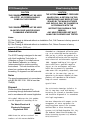
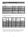
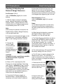
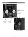
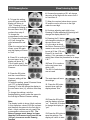
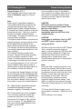
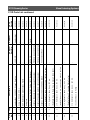
1
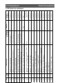
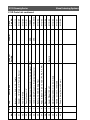
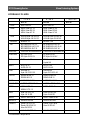
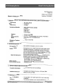
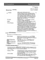
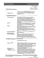
Instruction Manual Huck Model 911D Diesel Engine Hydraulic Powerig Manufacturer: Alcoa Fastening Systems Ltd; Telford, United Kingdom Form No. 911D ENG Rev. 24.11.09 911D Powerig Series Alcoa Fastening Systems (911D) 911D Powerig Series Alcoa Fastening Systems Contents Safety Guidelines when using Huck Installation Equipment to install Huck Fasteners 1 Description 4 Specification 4 Disposal 5 Utilisation 6 Servicing Powerig 7 Principle of operation 8 Main Components 9, 10 911D Hydraulic Schematic 11 911D Electrical Schematic 12 Preparation for First Time Use 13 Checking and Adjusting Pull, Return & Swage Pressures 15 Preparartion for regular use 21 911D Parts List 22, 23, 24, 25 Preventive Maintenance/Maintenance 26 Hydraulic Fluids 28 Hydraulic Oil Information & MSDS (Material Safety Data Sheet) 29 911D Powerig Series Alcoa Fastening Systems HUCK FASTENING SYSTEMS Safety Guidelines when using Huck Installation Equipment to install Huck Fasteners. Before using equipment: 1) Only Huck Installation Equipment should be used to install Huck fasteners. 2) Only persons that have received training approved by Huck International Ltd should use Huck Installation Equipment. 3) The Manuals and/or Data sheets and warning stickers/labels supplied with the Installation equipment should be studied before connecting the equipment to any primary power supply, in particular the following sections: • • • • • • • Warnings and Cautions. Specifications Electrical and/or Air supply. Principals of Operation. Preparation for use. Regular use. Regular maintenance. 4) With hydraulic tooling, ensure that it is suitable for use with the Huck Powerig or Huck approved hand pump being used. 7) Visually check all pneumatic and/or hydraulic hoses, electrical cables, Powerigs, hand pumps and hand tools, for any visible signs of damage and leakage. ALL HYDRAULIC HOSES SHOULD BE RENEWED EVERY FIVE YEARS. 8) Do not connect any equipment to primary power supplies or attempt to use any equipment, that shows signs of damage or leakage. 9) Ensure that all air and/or hydraulic hose and/or electrical plugs/connectors are correctly connected before switching on supply to equipment. When operating the equipment: 10) When using fasteners in some types of structure, the fracturing of the Pintail during installation may generate noise levels above the first action level of the Noise at Work Regulations and therefore hearing protection must be worn. 11) It is recommended that eye protection, (e.g.. safety glasses), should be worn by the operator. 12) Never look directly at the front or rear of the installation tool. 5) Check that the Powerig or approved hand pump "Pull" and "Return" pressures have been adjusted to suit the tool being used. Reference must be made to the instruction manual supplied with the equipment. 13) Never hold the Installation Tool around the Nose Assembly. 6) Check that the Nose Assembly is of the correct type suitable for installing the fastener being used. 15) Warning Fasteners should only ever be installed in the actual workpiece to prevent possible high velocity ejection from the Nose Assembly due to tensile forces induced during Pintail fracture. 14) Keep hands/fingers clear of any moving parts and also apertures in Nose Assemblies. 911D Powerig Series Alcoa Fastening Systems 16) When using two piece fasteners, (i.e.. Pin and Collar type), the conical/chamfered end of the collar MUST always be towards the Nose assembly, NOT against the work piece. 17) Keep fingers clear from the underside of the head, collars and blind side of fasteners and from within the joint being fastened, during the installation cycle. 18) Do not look directly at the head or blind side of fasteners during the installation cycle. 21) Beware of fastener Pintails which are ejected, (sometimes forcibly), from the tool at the completion, or at Pintail fracture, during the installation cycle. Tools designed to have Pintail Deflectors and or catchers must never be used without them. 22) Do not continue to use any equipment which develops a fault whilst being used. 23) Avoid kinking of hoses or dragging of hoses and electrical cables over sharp objects. 19) During the installation cycle, the tool will pull and straighten itself to the axis of the fastener, beware of hands being trapped against any nearby structure. KEEP HANDS CLEAR 20) In the event of any difficulty whilst installing a fastener, releasing the tool trigger at any time during the installation cycle will immediately put the tool into reverse. Note The following symbols are attached to the equipment: The equipment ,meets the requirements of CE Certification. Read the Instruction Manual before using or maintaining this equipment. Wear eye protection when using this equipment. 911D Powerig Series Alcoa Fastening Systems CAUTION BEFORE OPERATING THIS POWERIG, READ THE SEPA R ATE DIESEL ENGINE INSTRUCTION MANUALS PROVIDED. WITH THIS POWERIG. IN PARTICULAR, PAY ATTENTION TO A N Y SAFETY INSTRUCTIONS, CAUTIONS A N D W ARNINGS. 911D Powerig Series Alcoa Fastening Systems Description The 911D diesel engine Powerig is designed to be used with a wide range of Huck hydraulic Installation Tools (including Bobtail Tools -see utilisation ), and will operate one Tool. The maximum Pull Pressure is 700 bar (10150 psi) and the maximum Return Pressure is 400 bar ( 5800 psi). The Powerig is equipped with a 12 vdc Battery and an electric Starter Motor operated by a Key Switch. The Engine and Pump run continuously and a low hydraulic pressure , (Idle Pressure ), ensures that the Tool Piston is kept in the forward position when the Tool is not being used. The Installation Tool is connected to the Powerig by means of Pull and Return pressure Hydraulic Hoses and an electrical Control Cord. The Powerig Hydraulic Directional Valve (HDV), is controlled from the Installation Tool Trigger by a 12 VDC remote control circuit. When operating ST & DT type Bobtail Tools, or non-Bobtail Tools, the operator presses and holds the Tool Trigger which starts the Tool cycle to install the Specification Fastener. Once the Fastener is installed, the Trigger is released and the Tool Piston and Nose Assembly return to the fully forward position, the Tool/Nose Assembly are ejected from the installed Fastener. When operating “IT” type Bobtail Tools, a Limit Switch (sometimes referred to as a Micro-Switch), & a red LED Light on the Tool are activated when the Nose Assembly is correctly located onto the Fastener. The Tool Trigger will only function if the Limit Switch has been activated (indicated by the red LED). The operator now presses and holds the Trigger which starts the Tool cycle to install the Fastener. As long as the Trigger is kept pressed, the Bobtail Collar will be Swaged correctly and the Tool and Nose Assembly will return and eject from the installed Fastener automatically. “ST” type Bobtail Tools also have a MicroSwitch and LED light but the operator has to release the Trigger when the Bobtail Collar is fully swaged. “DT” Tools also function that way but do not have a Limit Switch or LED. Powerig type Flow L/min (Imp. Gals/min) (at Engine speed of 1800 RPM) Pull Pressure max. bar (psi) (See Note 1, page 5) Swage Pressure max. bar (psi) Return Pressure max. bar (psi) (See Note 2, page 5) Diesel Engine, single cylinder (see separate Manual for additional information) Hydraulic Pump Control Circuit Starter Motor Circuit Battery Noise Hydraulic Oil Reservoir capacity max ltrs (imp. Gals) Length mm (inches) (without removable Handles) W idth (including wheels) mm (inches) Height mm (inches) Diameter of min wheels mm (inches) W eight including fluid Kg (lbs) 911d 1.22 (0.26) 700 (10150) 600 (8700) 600 (8700) Lombardini 15LD350 Axial, 4 piston 12 VDC via Alternator 12 VDC via Battery 12 VDC 55 Amp Hour TBA 14.0 (3.11) 850 (33 ‰ ) 650 (26) 750 (29.5) 200 (7.5 ) 158 (344) 911D Powerig Series CAUTION THE POWERIG SHOULD NOT BE USED AS A STEP. NO PERSON SHOULD CLIMB ON THE POWERIG. CAUTION THE POWERIG SHOULD NOT BE USED IN AN EXPLOSIVE AND/OR HIGHLY FLAMMABLE ATMOSPHERE Alcoa Fastening Systems CAUTION THE HYDRAULIC OUTPUT PRESSURE VALVES (PULL & RETURN) ON THIS POWERIG MAY HAVE BEEN SET AND SEALED BY THE MANUFACTURER AND SHOULD ONLY BE CHANGED IN ACCORDANCE WITH THE INSTRUCTIONS SHOWN IN THIS MANUAL. ANY NEW PRESSURES SET MUST ALWAYS BE CHECKED AND TESTED. Notes: 1) If the Powerig is delivered without an Installation Tool, Pull Pressure is factory preset at 510 bar, (7400 psi). 2) If the Powerig is delivered without an Installation Tool, Return Pressure is factory preset at 221 bar, (3200 psi). Intended Use The 911D Powerig is designed to be used with Huck Installation Tools (refer to Utilisation on Page 5), to install various Huck Bobtail Fasteners, in a factory (where permitted),or outdoor working environment. The unit should be not be placed on a surface with an angle exceeding 15 degrees from the horizontal. Noise The sound measurement is in accordance with BS EN ISO 3746: 1996 is less than 70dB(A). Disposal Fluids should be disposed of by processing through authorised methods and in accordance with current legislation. This symbol indicates that this product must be disposed of according to the The Waste Electrical & Electronic Equipment Regulations 2006 WEEE Directive and our national law. Products of this nature should be forwarded to a designated collection point e.g. on an authorised one-for-one basis when you buy a similar new product or to an authorised collection site for recycling waste electrical and electronic equipment (EEE). Improper handling of this type of waste could have a possible negative impact on the environment and human health due to potentially hazardous substances that are generally associated with EEE. At the same time, your cooperation in the correct disposal of these products will contribute to the effective usage of natural resources. Special Note The 911D Series Powerigs include a 12 VDC 55 Amp Hour Lead Acid Battery. Batteries are classed as hazardous waste and should be disposed of in accordance with legal requirements. For more information with respect to the management of waste equipment for recycling please contact our Customer Services desk at Alcoa Fastening Systems Ltd, Telford Shropshire TF3 3BQ. The Producer Identification Number for Alcoa Fastening Systems Ltd, Telford is: WEE/AF0044SY 911D Powerig Series Alcoa Fastening Systems Utilisation Non-Bobtail Tools Huck Tool Series/Model Pull Pressure Max. bar/psi Return Pressure Max. bar/psi 2400, 2480 (See Note below) 2502, 2503 (See Note below) 2580 Series 2600 Series 2620,2624, 2628, 2630 Series 506, 507, 585, 586, 5901, 516, 520, 524, 528, 532, 536 6042, 7042, 8042 579/8400 579/8400 393/5700 393/5700 510/7400 393/5700 221/3200 165/2400 221/3200 193/2800 221/3200 165/2400 510/7400 221/3200 Note Pressures may be reduced for some smaller diameter Fasteners. Refer to appropriate Installation Tool Instruction Manual. Bobtail Tools Swage Pressure Bobtail Tool Pull Installation Model Fastener Pressure Nose Assy. Series Diameter Max. bar/psi Max. bar/psi Swage Pressure Collar Cutter Assy. Max. bar/psi BTT25 BTT25 BTT25 BTT35 BTT35 SFBTT20 BTT57 BTT57 235/3408 235/3408 290/4205 270/3915 270/3915 TBA TBA TBA 12 mm 12 mm 14 mm 16 mm 16 mm 16 mm 20 mm 20 mm 389/5640 389/5640 389/5640 380/5510 380/5510 TBA TBA TBA 289/4200 289/4200 340/4930 357/5177 357/5177 TBA TBA TBA Return Pressure Max. bar/psi 289/4200 289/4200 289/4200 350/5075 350/5075 Notes 1) The above Swage Pressures are only a guide and may have to be adjusted to obtain consistent correct Collar swaging. The Pull Pressure should always be a maximum of 60 (870 psi) to 100 bar (1450 psi) higher than the the Swage Pressure to minimise the risk of Bobtail (the part of the Fastener held by the Nose Assembly), fracture. 6 911D Powerig Series Alcoa Fastening Systems Pressures - definitions Pull Pressure: This is the maximum hydraulic pressure of the Pump which is set and adjusted with the Main Pressure Relief Valve (5). In particular, it controls the maximum hydraulic pressure applied to the front of the Tool Piston during the “Pull” stroke (Pulling on the Fastener Pintail), enabling the complete Fastener installation. Swage Pressure: Sometimes called Cut-Off Pressure, this is the hydraulic pressure which is applied to the front of the Tool Piston, enabling swaging of the Collar during the installation of Bobtail Fasteners when using IT type Bobtail Tools. This pressure is set using the Digital Pressure Switch (6) and is adjusted to ensure complete swaging of the Collar when the value of the set Swage Pressure is reached. This pressure will always be set lower than the Pull Pressure. Return Pressure: This is the hydraulic pressure applied to the rear of the Tool Piston and is set and adjusted with the Pressure Switch (7). In particular, it controls the maximum hydraulic pressure applied to the rear of the Tool Piston during the return stroke, enabling the Tool/Nose Assembly to eject from the installed Fastener. Servicing Powerig Only an appropriately qualified and competent person should service any Diesel Engine hydraulic or electrical components. A SEPARATE Manual is provided for the Diesel Engine. Alcoa Fastening Systems Account Managers and Systems Engineers are located in your area to offer assistance you require in solving your installation problems. If you need assistance by telephone, please call Alcoa Fastening Systems Customer Services at Telford UK. tel +44 1952 290011 911D Powerig Series Alcoa Fastening Systems Principle of Operation with Bobtail Tools Non Bobtail Tools When the tool trigger is depressed :Relay R2 is energised which also energises Relay R1 via contact R2-1 (latched in by the Digital Return Pressure Switch 7). Normally open Relay contacts R2-3 closes to operate the HDV 3 solenoid, allowing fluid through the HDV via outlet port P Normally closed Relay contacts R2-2 open, preventing the Return Pressure HDV solenoid from operating while the pull pressure HDV solenoid is energised. The Installation Tool Piston moves rearwards to begin the Fastener installation cycle. When the Installation Tool trigger is released, Relay R2 is de-energised, contacts R2-3 open to de-energise the HDV Pull Pressure solenoid. relay contacts R2-2 close to energise the Return Pressure solenoid, allowing fluid through the HDV via outlet port R. The Installation Tool piston moves forward. When the Piston reaches the fully forward position, pressure in the return line increases and opens the Digital Return Pressure Switch 7 contacts, which deenergises Relay R1. This also deenergises the HDV Return Pressure solenoid and the Digital Return Pressure Switch then recloses (re-closes-sets). The installation cycle is now complete. Bobtail Tools (when connected to the Powerig via the Multi-Pin Lemo Plug) When the Bobtail Tool Limit Switch is activated (LED Light on ), and the Tool trigger is pressed, Relay R3 is energised (and latched - see Note 1). which also energises relay R1 via contact R3-1 (latched in by the Digital Return Pressure switch). Normally open Relay contacts R3- 3 close to operate the HDV 3 Pull Pressure solenoid, allowing fluid through the HDV via outlet port P. Normally closed Relay contacts R3-2 open, preventing Return Pressure HDV solenoid from operating while the pull pressure HDV solenoid is energised. The Installation Tool Piston moves rearwards to begin the Fastener installation cycle When the Swage Pressure reaches the pressure set on the Digital Swage Pressure Switch 6 Relay R4 energises and latches in via Relay R1-3 and Relay R4-2 contacts. Normally closed Relay R4-1 contacts open and de-energises Relay R3. R3-3 contacts open to de-energise the HDV Pull Pressure solenoid. Relay R3-2 contacts close to energise the HDV Return Pressure solenoid allowing fluid through the HDV outlet port R The Installation Tool Piston moves forward. When the Piston reaches the fully forward position, pressure in the return line increases and opens the Digital Return Pressure Switch 7 which de-energises Relay R1. This also de-energises the HDV Return Pressure solenoid. The Digital Return Pressure Switch then recloses (recloses-sets). The installation cycle is now complete Notes: 1. The latching of Relay R3, allows the fastener installation to continue even if the Limit Switch contacts in the Tool open after activating the Tool Trigger. 911D Powerig Series Alcoa Fastening Systems 6 Digital Pressure Switch (Swage Pressure) 5 Main Pressure Relief Valve (Pull Pressure) 15/15A Oil Return Line Filter & Condition Gauge Fuel Tank Filler Cap 14 Filler/Strainer 41 Handle Screw in, removable) 7 Digital Pressure Switch (Swage Pressure) 16 Oil Level/Temp Gauge 1 Diesel Engine 19 Hydraulic Quick Disconnect Coupling (Return Pressure) 18 Hydraulic Quick Disconnect Coupling (Pull Pressure) 40 Main Wheel 34 12 VDC Electrical Connector (non Bobtail Tools or remote Triggers) 35 12 VDC Electrical Connector (Bobtail Tools) Key Start Switch (Starter Motor) Diesel Engine Indicator Lights Main Components FIG. 1 911D Powerig Series Alcoa Fastening Systems Throttle Control Lever Lock Throttle Control Lever Stop Lever (shown in Engine run position) Stop Lever (stop Engine position) Engine Controls Main Components FIG. 1A 911D Powerig Series Alcoa Fastening Systems Installation Tool P R 6 7 3 5 15/15A 2 1 LEGEND Ref. N0. 1 2 3 5 6 7 15 15A Part Number 911D/1 911D/2 911D/3 911D/5 911D/6 911D/7 911D/15 911D/15A Item Lombardini 15LD-350 Diesel Engine Pump Hydraulic Directional Valve Main Pressure Relief Valve (Pull Pressure) Digital Pressure Switch (Swage Pressure) Digital Pressure Switch (Return Pressure) Hydraulic Oil Return Line Filter Oil Filter Condition Gauge 911D Hydraulic Schematic FIG. 2 42 Fuse R2 R3 - 1 R1 R2 - 1 R1 - 1 911D Electrical Schematic 42 Fuse 3 HDV PULL PRESSURE SOLENOID 42 Fuse R3 - 3 R3 R4 - 1 B O B TAIL TO O L TRIGGER B O B TAIL TO O L LIMIT SWITCH NOTE: R1 TO R4 ARE RELAYS REF. 37 R2 - 3 3 HDV RETURN PRESSURE SOLENOID R3 - 2 R2 - 2 R1 - 2 7 DIGITAL P R E S S U R E SWITCH (RETURN PRESSURE) R4 - 2 R1 - 3 R4 6 DIGITAL P R E S S U R E SWITCH (PULL PRESSURE) DIGITAL P R E S S U R E SWITCH (PULL PRESSURE) HDV PULL P R E S S U R E SOLENOID HDV RETURN PRESSURE SOLENOID DIGITAL P R E S S U R E SWITCH (RETURN PRESSURE) 24 VDC SUPPLY LEMO PLUG/SOCKET C O N N E C TOR (BOBTAIL TOOLS) 911D Powerig Series Alcoa Fastening Systems 911D Powerig Series Alcoa Fastening Systems Preparation for First Time Use (Refer to FIG. 1 ) 1. Check the diesel engine oil level by using the dipstick. The oil level should be near the maximum. If necessary add clean oil via the filler cap. Note: Refer to the Diesel Engine maintenance Manual for correct grade of oil. 2. Open air cleaner and remove element. CAUTION To avoid explosions or fire outbreaks, do not smoke or use naked flames during operations. Fuel vapours are highly toxic. Only carry out operations outdoors or in a well ventilated area. Keep face well away from the filler cap and fuel tank to prevent inhalation of harmful vapours. Dispose of fuel in accordance with applicable laws and regulations as it is highly polluting. Use the same type of fuel as used in cars as use of other types could damage the engine. The cetane rating of the fuel must be higher than 45 to prevent difficult starting. Do not use dirty fuel of mixtures of diesel fuel and water, since this would cause serious engine damage 5. Check that there is sufficient engine diesel fuel for the time intended to operate the Powerig. A full tank of fuel will run the engine for approx. 4 hours at 2400 r.p.m. Do not fill the fuel tank completely but just up to 1 cm (0.39”) from the top of the fuel tank. This allows space for fuel movement. Only use clean fuel and wipe any fuel spillage from the engine before starting. 6. Using the Oil Level/Temp Gauge 16, check that the hydraulic fluid (oil) level is at the top of the glass. To avoid overheating of the fluid, the level should not be allowed to fall lower than half way down the glass. . 3. Fill with engine oil up to the level mark. 4. Reassemble air cleaner. Ensure that the air filter is mounted the correct way otherwise dust and other impurities could enter the intake ducts. 7. If necessary, remove Filler Cap 14 and fill Powerig Oil Reservoir with recommended hydraulic fluid, (refer to page 28) to the top of the glass. CAUTION For filling the reservoir, only use clean fluid and a clean funnel with a maximum of a 60 micron filter. Failure to do this will cause malfunction and component damage. 8. Reinstall Filler Cap. 911D Powerig Series Starting & stopping the engine... 9. Apply the brake on the Castor Wheel to avoid unexpected movement of the Powerig during operation. Push down with foot to operate brake. Throttle Lever Lock Throttle Lever Starting... 10. Set the throttle at 50% maximum speed. 11. Turn the key clockwise to position 1 as shown below. The warning light should illuminate. 12. Continue to turn the key clockwise to position 2 to operate the electric starter motor. Release the key once the engine has started. The key will now return to position 1 and should be left in this position whilst the engine is running. CAUTION Do not operate the starter for more than 20 seconds at a time. If the engine does not start, wait 1 minute before trying again. If the engine does not start after two attempts, trace the cause according to the Diagnosis Chart (page 75 - 77) of the Diesel Engine Maintenance Manual. All warning lights should stay off when the engine is running. Alcoa Fastening Systems Note: If there is not enough battery power to operate the electric starter motor, the engine maybe started with the recoil starter. Refer to page 53 of the Diesel Engine Maintenance Manual for instructions. 13. Move throttle lever to the idle position and allow engine to run at idle for a few minutes before increasing speed and putting under load. Note: During the first 50 hours of running the engine, do not exceed 70% of maximum load. Stopping... 14. Move throttle lever to the idle position and allow engine to run at idle for a few minutes. 15. Move the stop lever fully to the left until the engine stops. 16. Rotate the key anticlockwise to the stop position. 911D Powerig Series Checking & Adjusting Pull, Return & Swage Pressures... Pull Pressure (FIG.4) (refer to Utilisation (page 6) for correct setting) 1. With the engine running at operating speed, observe the display on the Digital Pressure Switch (Swage Pressure). This will show the unit of measurement set and will periodically show “bAr” or “PSI”. Note: When facing the hydraulic connectors, the Digital Pressure Switch (Swage Pressure), is on the right hand side. 2. Connect a remote electrical trigger (or the plug/cable from a non-Bobtail Installation Tool), to the Powerig electrical connector 34. 3. Operate the remote Trigger momentarily and note pressure reading displayed on the Digital Pressure Switch. CAUTION Complete this test as quickly as possible to prevent overload of hydraulic components. 4. Refer to FIG. 4 and adjust the Pull Pressure to suit the Installation Tool being used. Refer to Utilisation (Page 6) and/or the Installation Tool Instruction Manual for correct Pull Pressure setting. Only make small adjustments (1/4 turn) at one time. Do not remove any pre-installed washers or locknut from the adjusting screw. 5. Check the Pull Pressure again as described above. Repeat adjustment if necessary until correct value is obtained. Alcoa Fastening Systems 6. Once the Pull Pressure has been set, tighten the Lock Nut on the Adjustment Screw to ensure setting is retained. Check the pressure one more time to ensure it had not changed whilst tightening the Lock Nut. Return Pressure (FIG 4) (refer to Utilisation (page 6) for correct setting) Notes: a) The diesel engine does not have to be running during checking or adjustment of the return pressure but the key must be in position 1. b) When facing the hydraulic connectors, the Digital Pressure Switch (Return Pressure), is on the left hand side. c) The Digital Pressure Switches are able to measure two SEPARATE pressure switch points; S1 & S2. Only the S1 is used and for the Return Pressure, the normally closed (N/C) switch contacts are utilised. If the left hand indicator light is on, then the N/C contacts are closed. d) The reset pressures r1 & r2 should left at the factory setting of 50 bar (725 psi). e) The S1 button is used to change to the different menu items. The S2 button is used to access the menu items and the S1 button used again to change the settings of those menu items. 1. Press both the S1 & S2 buttons at the same time and the display will show the first menu item. 2. Press the S2 button and the current unit setting will be displayed. 911D Powerig Series Alcoa Fastening Systems Adjustment Screw Clockwise to increase Pull Pressure Anti-clockwise to decrease Pull Pressure Lock Nut 7 Digital Pressure Switch (Swage Pressure) 6 Digital Pressure Switch (Swage Pressure) 5 Main Pressure Relief Valve (Pull Pressure) FIG. 4 911D Powerig Series Alcoa Fastening Systems 6. Consecutive pressing of S1 will change the value of the digit over the cursor from 1 to 9 and then 0. 3. To keep this setting, press S2 again and the display will return to “Unit”. Pressing S1 now will change the display to the next menu item (S1); continue from step 5. To change the measurement units, press S1. Consecutive pressing of S1 will change the units between bAr and PSI. When the required unit is shown, press S2 again and the display will return to “Unit” 4. Press S1 to continue to the next menu item. The display will show “S1”. This is switch point 1, the value of this is the Return Pressure. 5. Press the S2 button and the current Return Pressure setting will be displayed. To keep this setting, press S2 several times until “S1” is displayed again. Pressing S1 now will change the display to the next menu item (r1); continue from step 9. To change the settings, note the flashing/blinking cursor under the space for the first digit of Return Pressure setting. Note: The display is able to show 4 digit numbers. In this example a value of 350 bar is shown and therefore the space for the first digit is blank. 4 digit numbers are only used if the measurement units are set to PSI. The Return Pressure must always be lower than the Pull Pressure by at least 6.9 bar (100 psi), to ensure correct Powerig 7. When the required value shown, press S2 and the cursor will move to the right under the next digit. 8. Continue adjusting each digit in turn. Pressing S2 after adjusting the last digit will change the display back to “S1”. 9. Pressing the S1 button will change the display to the next menu item. r1 is the value at which the Return Pressure (S1), resets to zero and should be set at 50 bar (725 psi). Press S2 to check the setting. If it is necessary to change the setting then follow the procedure as in steps 6 & 7. 10 Press S1 to continue to the next menu item which is S2. The S2 & r2 switch points are not used. The next steps will save the settings... 11. Press the S2 button several times until the display shows “Stor”. 12. Press the S2 button and the display will show “no”. Press the S1 button to change the display to “yes”. 13. Press the S2 button to save the settings. The display will return to zero. 911D Powerig Series Swage Pressure (FIG 4 (only applicable when using IT type tools. Refer to Utilisation (page 6) for correct setting) Note: When using IT type Bobtail Installation Tools, fitted to the Powerig connector 35 with the electrical 8 pin Lemo Plug, the Digital Pressure Switch (Swage Pressure) 6, controls the hydraulic pressure to the tool during the pull cycle. This in turn controls the amount (length) of Bobtail fastener Collar swage. The higher the pressure, the more the Collar is swaged. This Digital Pressure Switch is checked and adjusted using the same procedure as that for the Digital Pressure Switch for the Return Pressure as previously explained. The indicator will light not be illuminated as the normally open contacts should be in the open condition. Set a Swage Pressure just above the minimum required for the Nose Assembly Anvil to just lightly contact the Collar Flange. A circular witness mark around the Collar flange will indicate the Anvil contact. On most large diameter (12 mm (1/2”) and above), Bobtail Collars have a series of raised nodules around the flange which will be crushed by contact with the Anvil. Do not adjust the Swage Pressure too high as this increases the risk of Bobtail grooves being stripped/damaged or the Bobtail being broken away from the Pin. In either event, this will prevent a Bobtail Collar Cutter from being used to remove the installed fastener. 14. Inspect hoses, electrical cords and connections frequently for signs of damage or ageing. If necessary replace. 15. Connect both hoses of the Installation Tool, (or if being used with a Hose Set, connect the Hose Set), to the Powerig. Activate the Tool Trigger to fully cycle the Tool, or if using an “IT” type Bobtail Tool, then use a remote trigger attached to the Powerig connector 34. Note: Alcoa Fastening Systems It is not possible to cycle IT type Bobtail Tool s using it’s own trigger unless the tool Limit Switch is activated (contacts close). Therefore a remote Trigger as described above must be used. CAUTION BTT series tools do not have a Dump Valve to relieve hydraulic pressure from the front of the Piston. Therefore, release the trigger immediately when the tool Piston has stopped moving. CAUTION Some types of Installation Tool (e.g. BTT and SFBTT series, extend in length during operation. 16. When using tools other than BTT Bobtail Tools, continue to press the trigger for approx. 4 seconds when the Tool Piston has stopped moving. Release the Trigger and and allow the Tool Piston to return to the starting position. Repeat three times. This will ensure that any air in the hydraulic system is removed. Note: New Hose Sets or individual hoses my not contain any hydraulic fluid and the air must be removed. To do this, connect one pair of couplings at one end of the Hose set, to the Powerig. Connect the other pair of Hose set couplings to each other. With the Powerig running, activate the remote trigger/tool trigger and then release. Wait approx. 45 seconds, then stop the Powerig. Check the Powerig hydraulic oil level before continuing. 17. Check the Pull Pressure again and recloses-adjust if necessary. Tighten the Lock Nut to ensure settings to not change. 911D Powerig Series Alcoa Fastening Systems Connecting and testing a Bobtail Tool (after completing previous steps 1 to 17). 7. Prepare a sample joint with the Bobtail Fastener. Place the Collar (see note below), onto the Pin. IT type Bobtail Tools.... Note: Only Bobtail Fasteners of 12 mm (1/2”) diameter or larger, have thread form locking grooves into which a tab on the Collar locates. Rotating the Collar will enable it to be screwed hand tight to the joint face. 1. Inspect hoses, electrical cords and connections frequently for signs of damage or ageing. If necessary replace. 2. Remove the remote trigger from the Powerig. 3. Connect the Hydraulic Couplings of the Tool or Hose Set to the hydraulic couplings 18 & 19 of the Powerig. 4. Connect the plug of the Bobtail Tool or Hose Set to the Powerig Electrical Connector 35. WARNING TO AVOID THE RISK OF PERSONAL INJURY, TEMPORARILY DISCONNECT THE TOOL ELECTRICAL PLUG FROM THE POWERIG WHILST FITTING THE NOSE ASSEMBLY TO THE TOOL. 5. Attach the Nose Assembly to the tool in accordance with instructions contained in the Instruction Manual for the tool or as shown. 6. Check operation of the tool Limit Switches by locating the Bobtail part of the fastener as far as possible into the Nose Assembly Puller. The Limit Switch light on the Tool should illuminate. Note: The Powerig will not allow Fastener installation unless the tool Limit Switch is activated. If it fails to activate, then check that the Nose Assembly has been assembled onto the Tool correctly. Also, check for correct Limit Switch adjustment, (refer to the Instruction Manual for the tool). 8. Locate the Nose Assembly Puller onto the Bobtail grooves of the fastener Pin. The Nose Assembly should be in line with the axis of the fastener Pin. 9. Press and hold the tool Trigger. The Nose Assembly Puller will retract into the Anvil, closing around the end of Pin. The Anvil will be forced forward toward the Collar Flange to complete the Collar swaging/forming. When the Swage Pressure is reached, the Tool/Nose Assembly will eject automatically from the installed fastener, even if the Trigger is kept depressed. When the Nose Assembly Anvil is free from the Collar, the Puller will release from the end of the Pin and enable the Tool/Nose Assembly to be removed from the installed fastener. 10. Release the tool Trigger. 11. The installed fastener should be checked with the correct Bobtail Fastener inspection Gauge to ensure correct Collar swage. Adjust the Swage Pressure if necessary. Note: Set a Swage Pressure just above the minimum pressure required for the Nose Assembly Anvil to just lightly contact the Collar Flange. A circular witness mark around the Collar flange will indicate the Anvil contact. On most large diameter (12 mm (1/2”) and above), Bobtail Collars have a series of raised nodules around the flange 911D Powerig Series which will be crushed by contact with the Anvil. Do not adjust the Swage Pressure too high as this increases the risk of Bobtail grooves being stripped/damaged or the Bobtail being broken away from the pin. In either event, this will prevent a Bobtail Collar Cutter from being used. ST type Bobtail tools... These tools have a Limit Switch and operate in a similar way to the IT type tools except that the operator must release the tool Trigger to eject the Tool/Nose Assembly from the installed fastener. Follow steps 1 to 11 as for the IT type tools but in step 4. connect the plug of the Bobtail tool to the Powerig Electrical Connector 34 DT type Bobtail tools and non-Bobtail tools fitted with Bobtail Nose Assemblies... Note: When using DT type tools, the hydraulic Pull Pressure (as set with the Main Pressure Relief Valve 5), controls the Collar swaging. Ensure this has been adjusted to the correct value before attempting to install a fastener. The Digital Pressure Switch 6 is not utilised. 1. Inspect hoses, electrical cords and connections frequently for signs of damage or ageing. If necessary replace. 2. Remove the remote trigger from the Powerig. 3. Connect the Hydraulic Couplings of the Tool or Hose Set to the hydraulic couplings 18 & 19 of the Powerig. 4. Connect the plug of the Bobtail Tool or Hose Set to the Powerig Electrical Connector 34. Alcoa Fastening Systems WARNING TO AVOID THE RISK OF PERSONAL INJURY, TEMPORARILY DISCONNECT THE TOOL ELECTRICAL PLUG FROM THE POWERIG WHILST FITTING THE NOSE ASSEMBLY TO THE TOOL. 5. Attach the Nose Assembly to the tool in accordance with instructions contained in the Instruction Manual for the tool or as shown. 6. Prepare a sample joint with the Bobtail Fastener. Place the Collar (see note below), onto the Pin. Note: Only Bobtail Fasteners of 12 mm (1/2”) diameter or larger, have thread form locking grooves into which a tab on the Collar locates. Rotating the Collar will enable it to be screwed hand tight to the joint face. 8. Locate the Nose Assembly Puller onto the Bobtail grooves of the fastener Pin. The Nose Assembly should be in line with the axis of the fastener Pin. Note: DT type tools do not have a Limit Switch which means the tool Trigger is always enabled. Therefore, the operator must ensure that the Nose Assembly Puller is correctly located onto the Bobtail part of the fastener Pin before pressing the tool Trigger to start the installation cycle. Failure to do this may result in damage to the Puller and increases the risk of Bobtail grooves being stripped/damaged or the Bobtail being broken away from the pin. In either event, this may prevent the Collar from swaging correctly and will prevent a Bobtail Collar Cutter from being used to remove the installed fastener. 9. Press and hold the tool Trigger. The Nose Assembly Puller will retract into the 911D Powerig Series Anvil, closing around the end of Pin. The Anvil will be forced forward toward the Collar Flange to complete the Collar swaging/forming. 10. Release the tool Trigger when the Collar is fully swaged or the Nose Assembly stops moving. When the Nose Assembly Anvil is free from the Collar, the Puller will release from the end of the Pin and enable the Tool/Nose Assembly to be removed from the installed fastener. 11. The installed fastener should be checked with a Bobtail Fastener inspection Gauge to ensure correct Collar swage. Adjust the Main Pressure Relief Valve if necessary. Note: Set a Pull Pressure just above the minimum Alcoa Fastening Systems pressure required for the Nose Assembly Anvil to just lightly contact the Collar Flange. A circular witness mark around the Collar flange will indicate the Anvil contact. On most large diameter (12 mm (1/2”) and above), Bobtail Collars have a series of raised nodules around the flange which will be crushed by contact with the Anvil. Do not adjust the Pull Pressure too high as this increases the risk of Bobtail grooves being stripped/damaged or the Bobtail portion of the pin being broken away from the pin. In either event, this will prevent a Bobtail Collar Cutter from being used to remove the installed fastener Other tools used to install Pintail type fasteners... The Powerig Pull and Return Pressures should be set in accordance with the information in the Instruction Manual for Preparation for Regular Use Before each Powerig operation, perform the following: 1. Inspect hoses, electrical cords and connections frequently for signs of damage or ageing. If necessary replace. 2. Regularly check engine oil level and hydraulic fluid level. 3. Connect the Pull and Return Hydraulic Connectors of the Tool or Hose Set to the Powerig Hydraulic Connectors 18 & 19. Connect the Electrical Plug of the Tool or Hose Set to the Powerig connection 34 or 35 according to the tool being used. 4. Check that all electrical and hydraulic connectors of the Tool and Hose Sets are properly attached. 5. Cycle the Tool several times to circulate the oil through the Powerig valves, hoses and Tool. CAUTION Do not attempt to operate the Tool without the Tool hoses attached to the Powerig. When using HPT tools, release trigger immediately at the end of the pull stroke. 8. Powerig is ready for use. 911D Powerig Series Alcoa Fastening Systems 5 Main Pressure 15 Oil Relief Valve Return Line (Pull Pressure) Filter & Condition 14 Filler/Strainer Engine Oil Gauge Filler Cap 6 Digital Pressure Switch (Swage Pressure) Fuel Tank Filler Cap 1 Diesel Engine 7 Digital Pressure Switch (Return Pressure) 19 Hydraulic Quick Disconnect Coupling (Return Pressure) 41 Handle Screw in, removable) 34 12 VDC Electrical Connector (non Bobtail Tools 40 Main Wheel 35 12 VDC Electrical Connector or remote (Bobtail Tools) Triggers) 36 Battery 16 Oil 18 Hydraulic Quick Level/Temp Gauge Disconnect Coupling (Pull Pressure) 13 Hydraulic Hose 12 Hydraulic Hose 3 Hydraulic Directional Valve 39 Castor Wheel 37 Relay & Base (R1, R2, R3 & R4) 38 Electrical Enclosure Parts List 911D Powerig 42 Fuse Qty. 1 1 1 1 1 1 1 2 1 1 2 1 1 Ref. No. 1 2 3 4 5 6 7 8 9 10 11 12 13 (Oil Reservoir to Pump) 3/4 Hydraulic Hose Assy. 440 mm (Manifold Port P to under Relief valve) 1/4 Hydraulic Hose Assy.400 mm (Manifold Ports A & B to Pressure Switch Outlet) 1/4 Hydraulic Hose Assy.460 mm (Manifold Tee to Male Tee on Relief Tank Port) 3/8 Hydraulic Hose Assy.300 mm 3/8 Hydraulic Hose Assy.310 mm (Filter to Tee) Digital Pressure Switch Power Cable Digital Pressure Switch (Return Pressure) Digital Pressure Switch (Swage Pressure) Main Pressure Relief Valve (Pull Pressure) Subplate HDV (Hydraulic Directional Valve) Pump PF504H.XVB.1 Lombardini 15LD-350 Diesel Engine Description - - - - 804000E030M020 TECSIS S2400B087403 TECSIS S2400B087403 MVC41A - - - 15LD-350 Supplier Part No. - - - Voith - - Lombardini Supplier 911D/13 911D/12 911D/11 911D/10 911D/9 911D/8 911D/7 911D/6 911D/5 911D/4 911D/3 911D/2 911D/1 Huck Part No. 911D Powerig Series Alcoa Fastening Systems 911D Parts List continued Qty. No. 1 1 1 1 1 1 1 1 3 2 2 4 2 3 4 5 1 Ref. 14 15 15A 16 17 18 19 20 21 22 23 24 25 26 27 28 29 301/2 SIF-10A 10 CRS TP 102601 CRS L05127TE Adaptor - 3/4 BSP 12 SAE Dowty Washer 1/4 Dowty Washer 3/8 Swivel Tee - 1/4 BSP Female Adaptor - 1/4 BSP Male x 1/4 fixed Female Adaptor - 1/4 BSP Male Male Bush - 1/4 BSP Female x 3/8 NPT Bulkhead Adaptor - BSP 1/4 - - - - - - - - - Hydraulic Quick Disconnect Coupling (Return Pressure) Adaptor - 1/2 x 3/8 BSP Male - Adaptor - 3/8 x 1/4 BSP Male Supplier Part No. 45/F1315M90 - Hydraulic Quick Disconnect Coupling (Pull Pressure) Hydraulic Oil Filter/Breather (73 mm) Hydraulic Oil Level/Temp.Gauge (127 mm) Oil Filter Condition Gauge Hydraulic Oil Return Line Filter RTF3/10 Hydraulic Oil Filler ST34B Description - - - - - - - - - - AFS - - - - Supplier 911D/27 911D/26 911D/25 911D/24 911D/23 911D/22 911D/21 911D/20 911D/19 only available as a pair 10440 911D/18 911D/17 911D/16 911D/15A 911D/15 911D/14 Huck Part No. 911D Powerig Series Alcoa Fastening Systems 911D Parts List continued 1 1 1 1 1 1 1 4 1 1 2 2 3 30 31 32 33 34 35 36 37 38 39 40 41 42 No. Ref. Description - - - - Supplier Part No. Fuse - 5 Amp (5 mm x 20 mm) Handle - screw in, removable Main Wheel 200 mm x 20 mm bore Castor Wheel 100 x 27 Electrical Enclosure Relay & Base - 14 pin 12 VDC (R1, R2, R3, R4) Battery - 12 VDC 55 Amp Hour 12 VDC Multi-Pin Lemo Electrical Connector - - - Flexello - - - - 12 VDC Electrical Connector (for 2 pin Bayonet Plug) Dowty Washer 1/2” Tee - 3/8” Male Adaptor - 1/4” Male x 3/8” Female Swivel Adaptor - 1/4 Male x 3/8 Female Qty. - - - - - - - AFS AFS - - - - Supplier 911D/38 911D/37 911D/36 911D/35 911D/34 911D/33 911D/32 HKE-9076 110685 911D/31 911D/30 911D/29 911D/28 Huck Part No. 911D Powerig Series Alcoa Fastening Systems 911D Parts List continued 911D Powerig Series Alcoa Fastening Systems Preventive Maintenance 1. Before carrying out any maintenance, remove the key from the engine Key Switch to avoid accidental starting and electrical damage. manufacturer. 6. Refer to the engine manuals supplied with this Powerig for preventative maintenance details. 2. Regularly inspect the hydraulic fluid. If contamination particles larger than 20 um are present, then replace fluid. Good practice is to replace the hydraulic fluid every 12 Months to avoid ageing effects. Adding Hydraulic Fluid Note: The introduction of foreign material into the hydraulic system can result in poor performance and repair downtime. Observe the following practices: 2. Remove the screws from the top cover and remove cover. This will provide better access to the Filler. Alternatively, use a short length of flexible tubing between the funnel and the filler. 3. When filling or adding oil, always use a clean funnel with a maximum 60 micron filter. Ensure that correct fluid is used. 3. Before removing the filler cap, use a clean wipe to remove any accumulated dirt from the filler cap and surrounding area. Remove the filler cap. 4. Always ensure that hose couplings are free from dirt before attachment of Tools. 5. All hydraulic hoses should be renewed every five years. Notes: A) Mixing different manufacturers/kinds of hydraulic oil can cause a chemical reaction relating to resin or sludge. Contact the manufacturer for advise to avoid any problems. In any case, all traces of the original oil must be removed by rinsing (washing out) all hydraulic components. If filling/draining the Powerig, ensure that hydraulic fluids are not accidentally switched. B) Hydraulic fluids should be disposed of according to the environmental guidelines/legislation applicable in the country where the unit is being maintained and/or used. Please also consult the guidelines of your individual oil 1. Ensure that equipment is readily available to deal with any spillage of hydraulic fluid. 5. Locate a clean funnel into the filling port and place an absorbent wipe around the funnel spout to soak up any excess fluid. 6. Before adding any hydraulic fluid, check that it is the correct type and grade. (Refer to page 28). 7. Slowly add the new hydraulic fluid, pausing regularly to allow fluid in the funnel to flow into the pump reservoir and also preventing accidental spillage. 8. Continue to add fluid until it rises to the top of the Oil Level/Temperature Gauge glass. 9. Remove the funnel and replace the filler cap. Ensure filler cap is hand tightened. 10. Clean any fluid spillage with absorbent wipes. Replace cover and secure in place using the screws. 911D Powerig Series Draining Hydraulic Fluid...... 1. Ensure that equipment is readily available to deal with any spillage of hydraulic fluid. 2. If possible, place the Powerig onto an oil tray or draining sink sufficient to retain 14 ltrs (3.11 Gals.) of fluid. 3. Remove the screws from the rear cover and remove cover. 13 Hose Alcoa Fastening Systems to be made for any leakage from the hose connection. re-closes-tighten the hose connection if any leakage is observed. 8. Clean any remaining fluid spillage with absorbent wipes before replacing the rear cover and tightening the screws. Maintenance 1. Before carrying out any maintenance, remove the key from the engine to avoid accidental starting and electrical damage. 2. Electrical components are only allowed to be repaired and/or replaced by a qualified electrician. 3. Hydraulic components are only allowed to be repaired and/or replaced by a qualified mechanic. 4. Use a clean wipe to remove any accumulated dirt from around the area where Hydraulic Hose 13 is connected to the Pump. 5. Disconnect Hydraulic Hose 13 from the Pump and drain the oil into a suitable container which has a minimum capacity of 14 ltrs (3.11 Gals.). 6. After the oil has completely drained from the reservoir, re-closes-connect the hose to the pump and tighten. 7. Clean any fluid spillage with absorbent wipes. Note: Do not replace the rear cover until the reservoir has been re-closes-filled with new oil and the Powerig has been running for a few minutes. This will allow checks 4. Refer to the engine manuals supplied with this Powerig for further maintenance details. 911D Powerig Series Alcoa Fastening Systems HYDRAULIC FLUIDS * - <-- 0° C * 0° - 30° C HLP 32 HLP 46 AGIP AGIP OSO 35 AGIP OSO 45 ARAL ARAL Vitam GF 32 ARAL Vitam DE 32 ARAL Vitam HF 32 ARAL Vitam GF 46 ARAL Vitam DE 46 ARAL Vitam HF 46 AVIA AVILUB Hydr.-Oil RSL 32 AVILUB Hydr.-Oil HVI 32 AVILUB Hydr.-Oil RSL 46 AVILUB Hydr.-Oil HVI 46 BLASER BLASOL 157 BLASOL 158 BP BP ENERGOL HLP 32 BP ENERGOL HLP-D 32 BP ENERGOL SHF 32 BP ENERGOL HLP 46 BP ENERGOL HLP-D 46 BP ENERGOL SHF 46 CASTROL CASTROL HYSPIN AWS 32 CASTROL HYSPIN AWS 46 CHEVRON EP Hydr.-Oil 32 EP Hydr.-Oil 32 HV EP Hydr.-Oil 46 EP Hydr.-Oil 46 HV ELF ELF Acantis 32 ELF Acantis 46 Hydrelf 46 ESSO NUTO H 32 HLPD-OIL 32 NUTO H 46 HLPD-OIL 46 FINA HIDRAN 32 Hydr.-Oil D 3011-32 HIDRAN 46 Hydr.-Oil D 3011-46 FUCHS RENOLIN MR 10 RENOLIN B 10 RENOLIN MR 25 RENOLIN B 15 GULF HARMONY 32 AW HARMONY 46 AW HOUGHTON HYDROLUBRIC VG 32 HYDROLUBRIC VG 46 MOBIL MOBIL D.T.E. 24 MOBIL D.T.E. 13 MOBIL D.T.E. 25 OEST Hydr.-Oil H-LP 32 Hydr.-Oil 32 DD Hydr.-Oil H-LP 46 Hydr.-Oil 46 DD SHELL SHELL Tellus Oil 32 SHELL Tellus Oil 46 SUNOCO SUNVIS 816-WR SUNVIS 821-WR TEXACO Rando Oil HD A-32 Rando Oil HD AZ-32 Alcor Oil DD 32 Rando Oil HD B-46 Alcor Oil DD 46 VALVOLINE VALVOLINE ETC-25 VALVOLINE ETC-30 * Environment Temperature * 30° C --> + HLP 68 911D Powerig Series Alcoa Fastening Systems Important Note: The following pages contain the Material Safety Data Sheets (MSDS) for the Shell Tellus 46 Hydraulic Oil & the Esso Diesel Fuel which were both supplied with this Powerig when new. The MSDS for the engine oil is contained in the SEPA R ATE Diesel Engine manuals supplied with the Powerig. 911D Powerig Series Alcoa Fastening Systems 911D Powerig Series Alcoa Fastening Systems 911D Powerig Series Alcoa Fastening Systems 911D Powerig Series Alcoa Fastening Systems 911D Powerig Series Alcoa Fastening Systems 911D Powerig Series Alcoa Fastening Systems 911D Powerig Series Alcoa Fastening Systems 911D Powerig Series Alcoa Fastening Systems 911D Powerig Series Alcoa Fastening Systems 911D Powerig Series Alcoa Fastening Systems 911D Powerig Series Alcoa Fastening Systems 911D Powerig Series Alcoa Fastening Systems 911D Powerig Series Alcoa Fastening Systems 911D Powerig Series Alcoa Fastening Systems 911D Powerig Series Alcoa Fastening Systems 911D Powerig Series Alcoa Fastening Systems 911D Powerig Series Alcoa Fastening Systems 911D Powerig Series Alcoa Fastening Systems LIMITED WARRANTIES Tooling Warranty: Huck warrants that tooling and other items (excluding fasteners, and hereinafter referred as "other items") manufactured by Huck shall be free from defects in workmanship and materials for a period of ninety (90) days from the date of original purchase. Warranty on "non standard or custom manufactured products": With regard to nonstandard products or custom manufactured products to customer's specifications, Huck warrants for a period of ninety (90) days from the date of purchase that such products shall meet Buyer's specifications, be free of defects in workmanship and materials. Such warranty shall not be effective with respect to non-standard or custom products manufactured using buyer-supplied molds, material, tooling and fixtures that are not in good condition or repair and suitable for their intended purpose. THERE ARE NO WARRANTIES WHICH EXTEND BEYOND THE DESCRIPTION ON THE FACE HEREOF. HUCK MAKES NO OTHER WARRANTIES AND EXPRESSLY DISCLAIMS ANY OTHER WARRANTIES, INCLUDING IMPLIED WARRANTIES AS TO MERCHANTABILITY OR AS TO THE FITNESS OF THE TOOLING, OTHER ITEMS, NONSTANDARD OR CUSTOM MANUFACTURED PRODUCTS FOR ANY PARTICULAR PURPOSE AND HUCK SHALL NOT BE LIABLE FOR ANY LOSS OR DAMAGE, DIRECTLY OR INDIRECTLY, ARISING FROM THE USE OF SUCH TOOLING, OTHER ITEMS, NONSTANDARD OR CUSTOM MANUFACTURED PRODUCTS OR BREACH OF WARRANTY OR FOR ANY CLAIM FOR INCIDENTAL OR CONSEQUENTIAL DAMAGES. Huck's sole liability and Buyer's exclusive remedy for any breach of warranty shall be limited, at Huck's option, to replacement or repair, at FOB Huck's plant, of Huck manufactured tooling, other items, nonstandard or custom products found to be defective in specifications, workmanship and materials not otherwise the direct or indirect cause of Buyer supplied molds, material, tooling or fixtures. Buyer shall give Huck written notice of claims for defects within the ninety (90) day warranty period for tooling, other items, nonstandard or custom products described above and Huck shall inspect products for which such claim is made. Tooling, Part(s) and Other Items not manufactured by Huck. HUCK MAKES NO WARRANTY WITH RESPECT TO THE TOOLING, PART(S) OR OTHER ITEMS MANUFACTURED BY THIRD PARTIES. HUCK EXPRESSLY DISCLAIMS ANY WARRANTY EXPRESSED OR IMPLIED, AS TO THE MERCHANTABLITY OR FITNESS FOR USE OF ANY TOOL, PART(S), OR OTHER ITEMS THEREOF NOT MANUFACTURED BY HUCK. HUCK SHALL NOT BE LIABLE FOR ANY LOSS OR DAMAGE, DIRECTLY OR INDIRECTLY, ARISING FROM THE USE OF SUCH TOOLING, PART(S) OR OTHER ITEMS OR BREACH OF WARRANTY OR FOR ANY CLAIM FOR INCIDENTAL OR CONSEQUENTIAL DAMAGES. The only warranties made with respect to such tool, part(s) or other items thereof are those made by the manufacturer thereof and Huck agrees to cooperate with Buyer in enforcing such warranties when such action is necessary. Huck shall not be liable for any loss or damage resulting from delays or nonfulfillment of orders owing to strikes, fires, accidents, transportation companies or for any reason or reasons beyond the control of the Huck or its suppliers. Huck Installation Equipment Huck International, Inc. reserves the right to make changes in specifications and design and to discontinue models without notice. Huck Installation Equipment should be serviced by trained service technicians only. Always give the Serial Number of the equipment when corresponding or ordering service parts. Complete repair facilities are maintained by Huck International, Inc. Please contact one of the offices listed below. Eastern One Corporate Drive Kingston, New York 124010250 Telephone (845) 331-7300 FAX (845) 334-7333 Canada 6150 Kennedy Road Unit 10, Mississauga, Ontario, L5T 2J4, Canada. Telephone (905) 564-1825 FAX (905) 564-1963 Outside USA and Canada Contact your nearest Huck International Office, see back cover. In addition to the above repair facilities, there are Authorized Tool Service Centers (ATSC's) -located throughout the 'United States. These service centers offer repair services, spare parts, Service Parts Kits, Service Tools Kits and Nose Assemblies. Please contact your Huck Representative or the nearest Huck office listed on the back cover for the ATSC in your area. For the Long Haul™ A Global Organization Alcoa Fastening Systems (AFS) maintains company offices throughout the United States and Canada, with subsidiary offices in many other countries. Authorized AFS distributors are also located in many of the world’s industrial and Aerospace centers, where they provide a ready source of AFS fasteners, installation tools, tool parts, and application assistance. Alcoa Fastening Systems world-wide locations: Americas Alcoa Fastening Systems Alcoa Fastening Systems Aerospace Products Tucson Operations 3724 East Columbia Tucson, AZ 85714 800-234-4825 520-747-9898 FAX: 520-748-2142 Commercial Products Kingston Operations 1 Corporate Drive Kingston, NY 12401 800-431-3091 845-331-7300 FAX: 845-334-7333 www.hucktools.com Alcoa Fastening Systems Alcoa Fastening Systems Alcoa Fastening Systems Alcoa Fastening Systems Aerospace Products Carson Operations PO Box 5268 900 Watson Center Rd. Carson, CA 90749 800-421-1459 310-830-8200 FAX: 310-830-1436 Commercial Products Waco Operations PO Box 8117 8001 Imperial Drive Waco, TX 76714-8117 800-388-4825 254-776-2000 FAX: 254-751-5259 Far East Europe Alcoa Fastening Systems Alcoa Fastening Systems Commercial Products Australia Operations 14 Viewtech Place Rowville, Victoria Australia 3178 03-764-5500 Toll Free: 008-335-030 FAX: 03-764-5510 Commercial Products Canada Operations 6150 Kennedy Road, Unit 10 Mississagua, Ontario L5T2J4 Canada 905-564-4825 FAX: 905-564-1963 Commercial Products United Kingdom Operations Unit C, Stafford Park 7 Telford, Shropshire England TF3 3BQ 01952-290011 FAX: 0952-290459 Alcoa Fastening Systems Aerospace Products France Operations Clos D’Asseville BP4 95450 Us Par Vigny France 33-1-30-27-9500 FAX: 33-1-34-66-0600 Commercial Products Latin America Operations Avenida Parque Lira. 79-402 Tacubaya Mexico, D.F. C.P. 11850 FAX: 525-515-1776 TELEX: 1173530 LUKSME For The Long Haul, The Future of Fastening Technology, The Future of Assembly Technology, The Future of Tooling Technology, and Tools of Productivity are service marks of Huck International. Huck provides technical assistance regarding the use and application of Huck fasteners and tooling. products, and is not intended to create any warranty, express, implied, or statutory; all warranties are contained only in Huck’s written quotations, acknowledgements, and/or purchase orders. It is recommended that the user secure specific, up-to-date data and information regarding each application and/or use of such products. NOTICE: The information contained in this publication is only for general guidance with regard to properties of the products shown and/or the means for selecting such HWB898 1003-5M One Great ConnectionSM © 2003 Alcoa Fastening Systems 1 Corporate Drive, Kingston, NY 12401 • Tel: 800-431-3091 • Fax: 845-334-7333 • E-mail: [email protected] • www.alcoafasteningsystems.com