1
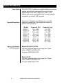
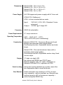
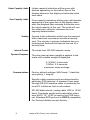
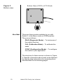
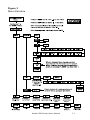
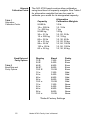
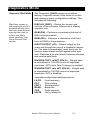
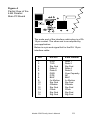
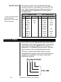
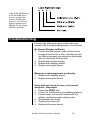
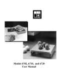
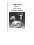
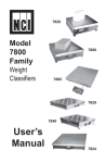
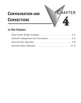
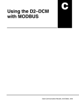
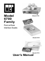
Model
6700
Family
Model 6720
Point-of-Sale
Interface Scales
Model 6702
Model 6710
User’s Manual
CAUTION
Risk of electrical shock. Do not remove cover. No user serviceable
parts inside. Refer servicing to qualified service personnel.
Weigh-Tronix reserves the right to change
specifications at any time.
03/12/02 6700_U.P65 PN 7424-14787E e1 Printed in USA
2
Model 6700 Family User’s Manual
Table of Contents
Specifications ...................................................... 4
Initial Setup ......................................................... 7
Operation ............................................................ 8
Menu Structure .................................................. 11
Diagnostics Mode .............................................. 13
Configuration Mode ........................................... 17
Calibration Mode ............................................... 19
Review/Test Scale Settings ............................... 21
Communication ................................................. 22
Error Codes ....................................................... 24
Troubleshooting................................................. 25
Spare Parts Listing ............................................ 27
Model 6700 Family User’s Manual
3
Specifications
Description
Capacity/Resolution
The NCI 6700 models are digital electronic bench
scales specifically designed for point-of-sale
applications and are “Legal-for-Trade.” The
scales are easily interfaced with a cash register,
computer or other POS terminal.
Important! Weights and Measures normally
requires inspection of scale before scale is
placed into operation.
Model
6702-7
6702-15
6710-7
6710-15
6720-7
6720-15
6720-30
6720-60
4740-15
Agency Certificates
of Conformance
Capacity (lb)
15 x .005
30 x .01
15 x .005
30 x .01
15 x .005
30 x .01
60 x .02
120 x .05
30 x .01
Capacity (kg)
7 x .002
15 x .005
7 x .002
15 x .005
7 x .002
15 x .005
30 x .01
60 x .02
15 x .005
Model 6702/6710/6720
US and Canada Approved Legal for Trade
USA: NTEP COC# 95-070
Canada: MOI# AM-5076
Model 4740
US and Canada Approved Legal for Trade
USA: NTEP COC# 92-151
Canada: MOI# AM-4778
4
Model 6700 Family User’s Manual
Dimensions
Power Supply
Model 6702: 10.4 x 6.4 x 2.5
Model 6710: 10.4 x 10.4 x 2.5
Model 6720: 14.1 x 12.6 x 4.1
Model 4740: 14.0 x 10.0
UL/CSA approved power supply with 6’ line cord
6702/6710: Wallmount
6720: In-line mounted below scale
Input:
120 VAC +10%-15%, Standard 3 wire
w/ground
Output: 15 VDC @.3 Amps DC
Frequency
Power Requirements
Operating Temperature
Construction
50/60 Hz selectable
0.1 amp maximum
42ºF – 104ºF (5ºC – 40ºC)
10% to 95% RH (non-condensing)
Models 6702/6710: Aluminum Base and Load
Bridge with stainless steel weigh platter.
Overload protection: Adjustable center and side
stops.
Model 6720: Die cast aluminum base with a
stainless steel weigh platter.
Overload protection: Adjustable center stop, fixed
corner stops.
Display
½" high, six-digit LCD.
Key panel with ZERO and TEST keys.
Remote display with 7 ft. cable. Standard on
Models 6702 and 6710, optional on 6720.
Scale Leveling
Using the leveling bubble as a guide, adjust the
four adjustable feet to level the scale.
Zero Window
Initial automatic zero setting is ±10% of maximum capacity—active at power up. Manual zero
setting range is ±2% of maximum capacity—
active using the ZERO key.
Model 6700 Family User’s Manual
5
Under Capacity Limits
Over Capacity Limits
Sealing
Internal Counts
Dynamic Response
Under capacity indication will be given with
dashes appearing on the bottom line of the
display whenever the display is below the initial
zero value.
Over capacity indication will be given with dashes
appearing in the upper line of the display whenever the weighed item exceeds 9 divisions over
the rated capacity of the unit. The scale will use
the initial zero value for reference for over
capacity determination.
Access to the calibration switch can be secured
with a lead wire or pressure sensitive security
seal. The remote or primary indicators have no
metrological features that require the use of a
security seal.
The scale has 100,000 internal counts.
The time interval when weight is applied to the
scale until a stable weight is displayed:
0–1000d,1.5 seconds
1000d+, 2.0 seconds
maximum mean average
Communications
Factory default settings: 9600 baud, 7 data bits,
even parity, 1 stop bit.
Specific cable requirements are determined by
particular POS terminal. A standard 9-pin pass
through RS-232 interface cable is necessary for
most PC interfaces. Not a null modem.
RS-232 bidirectional, configurable 1200 to 19.2K
baud. Transmits weight and scale status whenever ASCII “W” <CR> is sent by the POS terminal. Standard ECR protocol is OPOS compatible.
For Protocol details contact factory.
6
Model 6700 Family User’s Manual
Initial Setup
Unpacking the Scale
1. Remove contents of the shipping container.
2. Inspect the scale for evidence of shipping
damage. Immediately report any damage to
the shipper.
Installing the Scale
1. Mount the scale on a stable, level surface
that is free from air currents and vibration. Be
sure the scale platter does not touch any
adjacent surfaces.
2. To install the scale surface flush with a
countertop, use the dimensions on the
following page to guide construction.
Model 6702
Scale Dimensions
Min. Cut-Out Dimensions
D 10.4 in. (26.4 cm)
11.1 in. (28.2 cm)
W 6.4 in. (16.3 cm)
7.1 in. (18.0 cm)
H 2.5 in. (6.35 cm)*
*Adjustable to 3.0 in. (7.6 cm)
Model 6710
Scale Dimensions
Min. Cut-Out Dimensions
D 10.4 in. (26.4 cm)
11.1 in. (28.2 cm)
W 10.4 in. (26.4 cm)
11.1 in. (28.2 cm)
H 2.5 in. (6.35 cm)*
*Adjustable to 3.0 in. (7.6 cm)
Model 6720
Scale Dimensions
Min. Cut-Out Dimensions
D 12.6 in. (32.0 cm)
13.25 in. (33.7 cm)
W 14.1 in. (35.8 cm)
14.75 in. (37.5 cm)
H 4.1 in. (10.4 cm)*
*Adjustable to 4.6 in. (11.7 cm)
Model 6700 Family User’s Manual
7
3. Loosen the collets or jam nuts on the leveling
feet. Level the scale by using the level bubble
under the scale platter as a guide. Be sure all
four feet are in firm contact with the counter,
then tighten all collets and jam nuts.
4. Make sure all power cords, remote display
cables, etc., are not touching the live weighing surface.
5. Plug the unit into an appropriate voltage
outlet that is properly grounded.
6. The 6720 scale can support more than one
display; however, only one keypad is operable. Switch 3 selects internal or external
display keypad operation.
Switch 3 Settings
Closed= internal display keys operational
Open = external display keys operational
The normal setting for the 6720 with the
internal display is Switch 3=Closed. On 6720
w/remote only or 6710 and 6702 scales,
Switch 3=Open.
Operation
Power Up Test
Sequence
If RAM or ROM error
is reported, you must
press the TEST key to
acknowledge the
condition. See “Error
Codes” section.
When the scale is first powered up, it will perform
a test sequence. During this sequence, the
display will show the following:
• The model number and the software
version/revision level.
• A numeric counting test for all segments of
the display. During this test, a test of
Random Access Memory (RAM) and a test
of Read Only Memory (ROM) is performed.
If everything is OK, the display will show zero
weight and the scale is ready for use.
8
Model 6700 Family User’s Manual
Performing a Normal
Weighment
If the scale is outside
the ± 2% zero window,
center dashes are
displayed “- - - -.” If
necessary, reapply
power to reset the
initial zero setting.
1. With the scale powered on, make sure the
scale platter is empty and the display is at
zero. If it is not, press the ZERO key…
0.00 is displayed.
2. Place an item to be weighed on the scale
platter…
The scale will display the gross weight.
3. Remove the item from the scale platter.
Operation Controls
ZERO Key – The ZERO key will zero the scale if
weight is stable, and acts as the NO or SCROLL
key in the Menu mode.
TEST Key – The TEST key can be used to
perform the initial power-up test sequence, recall
diagnostic routines, or to view the scale configuration information. This key also acts as YES or
ACCEPT in the Menu mode.
Accessing the
Menu Mode
The 6700 models power up ready for weighing
operations. Access the Menu mode by setting
Switch 1 shown in Figure 1 or 2 to the OPEN or
Menu mode position.
Top View of 6720 Scale with Platter Removed.
Figure 1
6720 Switch
Location
Model 6700 Family User’s Manual
9
Figure 2
Bottom view
Menu Mode
Bottom View of 6702 or 6710 Scale
There are three modes available to you with
Switch 1 in the Menu mode or OPEN position.
They are as follows:
DIAG (Diagnostic Mode) – To test areas of
the scale’s function
CAL (Calibration Mode) – To calibrate the
scale
CONF (Configuration Mode) – To configure
the scale for your application
The structure for these menus is shown in Figure
3. Specific information about each mode followed
by step-by-step instructions for accessing them
are described in the following pages.
10
Model 6700 Family User’s Manual
Figure 3
Menu Structure
Model 6700 Family User’s Manual
11
Alternate
Calibration Points
Table 1
Alternative
Calibration Points
Baud Rate and
Parity Options
Table 2
Baud Rate and
Parity Options
The NCI 6700 bench scales allow calibration
using less than full capacity weights. See Table 1
for alternative weights that can be used to
calibrate your scale for its designated capacity.
Capacity
Alternative
Calibration Weights
9.995 lb
15 x .005 lb
7 x .002 kg
9.995 kg
30 x .01 lb
15 x .005 kg
60 x .02 lb
30 x .01 kg
99 x .05 lb
120 x .05 lb
60 x .02 kg
10 lb
10, 15 lb
7 kg
10 kg
10, 20, 30 lb
10, 15 kg
10, 30, 60 lb
10, 20, 30 kg
10, 50, 100 lb
10, 50, 100 lb
10, 30, 60 kg
Display
12 E
24 E
48 E
96 E*
19.2 E
12 o
24 o
48 o
96 o
19.2 o
12 n
24 n
48 n
96 n
19.2 n
Baud
1200
2400
4800
9600
19.2K
1200
2400
4800
9600
19.2K
1200
2400
4800
9600
19.2K
Parity
Even
Even
Even
Even
Even
Odd
Odd
Odd
Odd
Odd
None
None
None
None
None
*Default Factory Settings
12
Model 6700 Family User’s Manual
Diagnostics Mode
Diagnostic (DIAG) Mode
The Diagnostic (DIAG) mode menu allows
testing of specific areas of the scale’s function
and viewing current configuration settings. This
includes the following:
Tip: Easy access to
the diagnostic mode is
available directly from
the front panel without
opening the scale to
access the Menu
mode switches. See
Setup Review/Test
section.
DISPLAY (DISP) – Shows the version and
revision of the software, followed by a display
segment test.
RAM (RA) – Performs a nondestructive test of
RAM in the processor.
ROM (RO) – Performs a checksum of all locations of ROM in the processor.
INPUT/OUTPUT (I/O) – Data is output by the
scale and through the use of a loopback connector. The data is immediately read back into the
receive channel and verified against what was
sent. Requires a jumper (short) between transmit
and receive data lines.
DIVISION TEST, w/AZT (DIV-A) – Weight data
is normalized to 100,000 counts of displayed
resolution. AZT (Auto Zero Tracking) is enabled.
DIVISION TEST, w/o AZT (DIV-N) – Weight data
is normalized to 100,000 counts of displayed
resolution. AZT is disabled.
Viewable configuration settings include:
LN FR
FILT
PROT
BAUD
CAP
UNITS
Line frequency
Filter setting
Serial protocol
Baud rate
Scale capacity
Unit of measure
Model 6700 Family User’s Manual
13
Follow these steps to access the tests in the
DIAG menu.
1. From normal weighing mode, move Switch 1
to the Menu mode or OPEN position. (See
Figure 1 or 2).
If you encounter any
failure in these tests,
contact your local
Weigh-Tronix dealer.
DIAG is displayed.
2. Press the TEST key. . .
DISP is displayed. This stands for
display.
3. Press the TEST key to perform the display
test described earlier…
Display test is performed and the display
shows DISP after the test is completed.
4. Press the ZERO key…
RA is displayed. This stands for the RAM
test.
Press the ZERO key to
scroll through lists of
selections.
Press the TEST key to
make a selection.
To skip a test, press
the ZERO key to scroll
to the next test.
5. Press the TEST key to perform the RAM
test…
PASS or FAIL is displayed briefly; then
RA.
6. Press the ZERO key…
RO is displayed. This stands for the
ROM test.
7. Press the TEST key to perform the ROM
test . . .
PASS or FAIL is displayed briefly; then
RO.
8. Press the ZERO key…
I/O is displayed. This stands for the
INPUT/OUTPUT test.
14
Model 6700 Family User’s Manual
9-Pin RS-232 models:
9. With a loopback connector in place, press
the TEST key to perform the I/O test…
PASS or FAIL is displayed briefly, then
I/O. This test is only valid on 9-pin or
15-pin models configured as “RS” units.
On 15-Pin “RS” units,
jumper from Pin 1 to 2.
DIAG will flash every
15 seconds during the
high resolution test as
a reminder that you
are doing a test and
not seeing normal
weight readings.
10. Press the ZERO key . . .
DIV-A is displayed. This stands for the
high resolution DIVISION TEST W/AZT
enabled. See note at left.
11. Press the TEST key to perform this test…
The display shows the weight on the
scale at a resolution of 100,000 counts.
12. Press the TEST key to stop the test…
DIV-A is displayed.
13. Press the ZERO key…
DIV-N is displayed. This stands for the
high resolution DIVISION TEST w/o AZT
enabled.
14. Press the TEST key to perform this test…
The display shows the weight on the
scale at a resolution of 100,000 counts.
15. Press the TEST key to stop the test…
The remaining
selections are for
viewing current
settings only. You can
scroll through the
menu to verify the
settings, but to make
changes, you must
enter configuration or
calibration.
DIV-N is displayed.
16. Press the ZERO key…
LN FR is displayed. This stands for line
frequency.
17. Press the TEST key...
The current line frequency (50 or 60) is
displayed.
Model 6700 Family User’s Manual
15
18. Press the ZERO key…
FILT is displayed. This stands for filtering.
19. Press the TEST key…
The current filter setting, FAST or SLO,
is displayed.
18. Press the ZERO key…
PROT is displayed. This stands for
protocol.
19. Press the TEST key…
The current serial protocol selection is
displayed.
20. Press the ZERO key…
BAUD is displayed. This stands for baud
rate.
21. Press the TEST key…
The current baud rate and parity selection is displayed.
22. Press the ZERO key…
CAP is displayed. This stands for capacity.
23. Press the TEST key…
The current capacity/resolution selection
is displayed.
24. Press the ZERO key…
UNITS is displayed. This stands for unitof-measure.
25. Press the TEST key.
The current unit-of-measure LBS (for
pounds) or 1000G (for kilograms), is
displayed.
16
Model 6700 Family User’s Manual
26. When you are finished, press the ZERO key,
until DONE is displayed, then press the
TEST key to return to the top menu level…
DIAG is displayed. Or close Switch 1 to
return to normal weighing mode.
Configuration Mode
The Configuration (CONF) Mode menu allows
scale configuration for your specific application
needs. The items you can configure are as
follows:
FILTERING (FILT) – Choose between FAST and
SLO filtering. SLO should be chosen in areas
susceptible to vibration. Choose FAST filtering
for more stable conditions.
Baud (BAUD) – Choose a baud and parity from
Table 2.
Protocol (PROT) – Select the RS-232 communication protocol.
NCI – NCI standard
ECR – Cash register compatible
8213 – 8213 compatible (Sharp)
2250 – 2250 compatible (Swintec)
34-F – 34-MF compatible (Sweda-Mexico)
ATT – AT&T compatible
o4000 – Olympia Cash Register compatible
Access the Menu mode as shown in Figure 3.
1. From the DIAG display, press the ZERO key
until CONF is displayed, or from the normal
weighing mode, move Switch 1 to the Menu
mode or the OPEN position; then press the
ZERO key until CONF is displayed.
Model 6700 Family User’s Manual
17
2. Press the TEST key…
FILT is displayed.
3. Press the TEST key…
The current setting, FAST or SLO,
is displayed.
4. Use the ZERO key to toggle between the two
choices. Press the TEST key when the
choice you want is displayed. The choice is
accepted and the display shows the FILT
item.
5. Press the ZERO key…
BAUD is displayed.
6. Press the TEST key…
The current baud and parity choice is
displayed.
7. Use the ZERO key to scroll the choices
found in Table 2. When the choice you want
is displayed, press the TEST key. The choice
is accepted, and the display shows the BAUD
item.
8. Press the ZERO key until…
PROT is displayed.
9. Press the TEST key…
The current RS-232 communication
protocol is displayed.
10. Press the ZERO key to scroll through the
choices. When the choice you want is
displayed, press the TEST key. The choice is
accepted and the display shows the PROT
item.
18
Model 6700 Family User’s Manual
Calibration Mode
The Calibration (CAL) Mode menu lets you
calibrate your scale. The items in the calibration
menu are as follows:
POUNDS/KILOGRAMS (LBS or 1000 Gr) –
Selects the unit of measure of your calibration
test weights (lb or kg).
Step-by-Step
Instructions
for CAL Mode
CAPACITY (9.995, 15.005, 30.01, 60.02 etc.) –
Select the capacity of the scale.
Follow these steps to calibrate the scale. Refer to
Figure 3.
1. From the DIAG display, press the ZERO key
until CAL is displayed, or from the normal
weighing mode, move Switch 1 to the Menu
mode or OPEN position. Press the ZERO
key until CAL is displayed.
2. Press the TEST key…
50 H or 60 H is displayed. This is the AC
line frequency.
3. Press the ZERO key to toggle between the
choices. When the choice you want is
displayed, press the TEST key…
That choice is accepted and LB or KILO
is displayed.
4. Press the ZERO key to toggle between the
choices. When the choice you want is
displayed, press the TEST key…
The scale capacity is displayed.
(Example: 9.995)
If a different capacity selection is desired,
press the ZERO key to scroll through the
choices.
Model 6700 Family User’s Manual
19
5. When the desired capacity is displayed,
press the TEST key. . .
That choice is accepted and LOAD 0 is
displayed.
The capacity selected
must correlate with the
rated capacity of the
scale noted on the
serial tag.
6. Clear all weight from the scale platter and
press the TEST key…
After a brief wait LOAD xx is displayed.
Alternate calibration points can be
chosen using the ZERO key to scroll
between choices (see Table 1).
7. Place the appropriate calibration weights on
the scale and press the TEST key. After a
brief wait…
DONE is displayed.
8. Remove all calibration weights from scale.
If this procedure is
attempted without any
calibration weights
applied, the scale will
abort the process and
retain the original
calibration data.
9. Press the TEST key…
DIAG is displayed, or return Switch 1 to
the closed position. The scale returns to
normal weighing mode.
The scale is now tested, configured, and calibrated. It is ready for use in your application.
20
Model 6700 Family User’s Manual
Review/Test Scale Settings
IMPORTANT: If you
press and release the
TEST key, the display
will show the scales
model number,
version-revision, and
performs a display
test.
To review the current
system settings, press
and hold the TEST
until the display shows
dashes
“_ _ _ _.” Release the
TEST key and the
display will prompt
DISP and
the scale is now in the
Review/Test Mode.
The TEST key located on the front panel lets you
perform some basic system diagnostics, as well
as review the current system settings without
having to access switches inside the scale.
Press the ZERO key to
move to the next item
in the menu
Press the TEST key to
select the displayed
item to run or view.
IMPORTANT: Internal
rocker switches will be
ignored until you exit
this special mode or
power reset the scale.
When finished running tests or viewing the
settings, press the ZERO key until DONE is
displayed. Then press the TEST key to return to
normal (i.e., weighing) mode of operation.
Model 6700 Family User’s Manual
21
Communication
The 6700 is capable of interfacing with an EIA
Standard RS-232, full duplex, asynchronous,
smart device, or 4-bit parallel interface for
output of weight data to an ECR device. The
6700 15 pin style is normally configured as a 4bit Parallel standard from the factory. The 6700
9-pin style is capable of RS-232 communication
only.
Communications
Enabled
Serial Data
Transmission
Modem control lines
will not be supported
for RS-232
Serial commands will be responded to only
when the scale is in the ‘normal’ operating
mode and Switch 1 on the main board is in the
CLOSED position.
Baud Rates:
1200, 2400, 4800, 9600, or 19.2K
Word Length: 10 Bits
1 Start, 7 Data, 1 Parity, 1 Stop
Parity: Even, Odd, or None
The scale is DTE.
4-Bit Parallel
ECR Interface
The 15 pin version of the 6700 is normally
shipped configured to function as a 4-bit
parallel interface device.
Follow these steps to configure the scale to
serial RS-232 interface operation.
1. Locate the dip shunt jumper at JMP2 on the
main PC board.
2. Place the jumper so the shorting pins are
located away from the DE-15 connector at
end of the PC board. See Figure 4 below.
22
Model 6700 Family User’s Manual
Figure 4
Partial View of the
4-Bit Parallel
Main PC Board
The scale end of the interface cable plug is a DA
15 pin socket. The other end is as required by
your application.
Below is a pin and signal list for the DA 15 pin
interface cable.
Pin
RS-232
4-Bit Parallel
1
2
3
4
5
6
7
8
9
10
11
12
13
14
15
RXD
TXD
Sig Gnd
Data 4
Data 8
DSR
DTR
BHZ
/In Motion
Sig Gnd
/Enable
Sig Gnd
Clock
Sig Gnd
Sig Gnd
Data 1
Data 2
Sig Gnd
Data 4
Data 8
Over Capacity
NC
BHZ
/In Motion
Sig Gnd
/Enable
Sig Gnd
Clock
Sig Gnd
Sig Gnd
Model 6700 Family User’s Manual
23
RS-232 Interface
The 9-pin version of the 6700 has DE type
female connector accessible at the rear of the
unit. The functional pinout of this connector is
compatible with a standard PC with a passthrough cable.
DE-9 Female Scale
* Jmp1 and Jmp2 pins
are connected
internally on the scale
PCB connector.
DE-9 Male Host
Pin Name Direction Pin Name Direction
1.
JMP 1
-
1.
DCD
IN
2.
TXD
OUT
2.
RXD
IN
3.
RXD
IN
3.
TXD
OUT
4.
JMP 1
-
4.
DTR
OUT
5.
SG
-
5.
GRD
-
6.
JMP 1
-
6.
DSR
IN
7.
JMP 2
-
7.
RTS
OUT
8.
JMP 2
-
8.
CTS
IN
9.
NC
-
9.
RI
IN
Error Codes
Any system errors detected by the scale will be
displayed as the letter E followed by a two-digit
error code. Press the TEST key to continue
operation. If a calibration error occurs, the only
way to clear it is by recalibrating the scale.
The error codes are broken down into two
hexadecimal numbers, with each bit defining a
single error condition. The error codes are
defined as follows:
24
Model 6700 Family User’s Manual
If an E-02 ROM error
or E-04 RAM error
occurs, power the
scale off and then
back on. If it occurs
again contact your
Weigh-Tronix scale
service provider.
Troubleshooting
Perform the following steps in the order presented until the described problem is corrected.
No Power (Display is Blank)
1. Check that the primary side of the cord is
plugged into the AC outlet, and the secondary side is properly connected to the power
jack on the back of the scale.
2. Replace the power supply.
3. Replace the display board.
4. Replace the main board.
Missing or extra segments on display
1. Replace the display board.
2. Replace the main board.
Scale will not return to zero, or incorrect
weight is displayed
1. Press the ZERO key.
2. Check for interference of weighing platform.
3. Power down, remove all items from the
platter, and then power up the scale.
4. Recalibrate the scale.
5. Replace the load cell.
6. Replace the main board.
Model 6700 Family User’s Manual
25
Display shows unrecognized characters
1. Check software PROM for proper insertion.
2. Check display cables for the proper connection.
3. Replace PROM.
4. Replace the display board.
5. Replace the main board.
Display shows under “_ _ _ _” dashes
(Indicates that the scale is below zero or under
capacity.)
1. Verify that weigh platter is on the scale.
2. Press the ZERO key.
3. Power down, remove any items from the
platter, and then power up the scale.
4. Recalibrate the scale.
5. Replace the load cell.
6. Replace the main board.
Display shows center“_ _ _ _” dashes
(Indicates that the scale is outside zero capacity
of ±2%.)
1. Verify that weigh platter is on the scale.
2. Press the ZERO key.
3. Power down, remove any items from the
platter, and then power up the scale.
4. Recalibrate the scale.
5. Replace the load cell.
6. Replace the main board.
Display shows upper” _ _ _ _ “ dashes
(Indicates the scale is over capacity.)
1.
2.
3.
4.
5.
6.
26
Remove all items from the scale.
Press the ZERO key.
Power down, and then power up the scale.
Recalibrate the scale.
Replace the load cell.
Replace the main board.
Model 6700 Family User’s Manual
Scale is not transmitting data to the host
device
1. Check cable connection at both the rear
of the scale and the host device.
2. Check communication setting and baud rate
on both scale and software.
3. Perform I/O loopback test.
4. Replace the cable.
5. Replace the main board.
The ZERO key and the TEST key do not
function
1. Open display enclosure and verify that the
keypad cable is still installed correctly.
2. Replace the display panel.
3. Replace the display PCB.
4. Replace the display cable.
5. Replace the main PCB.
Spare Parts Listing
DESCRIPTION
PART NUMBER
Keyboard Panel
1163-13205
Display PCB
7405-15465
RS-232 PCB
7405-14704-2
4 Bit Parallel PCB
7405-14653-2
40 Bit Serial PCB
7405-14864-2
Power Supply - 6702/6710 1148-15535
Power Supply - 6720
1148-15536
RS-232 Cable - PC
1140-13842
6700-7 Kg Loadcell
7154-16323-07
6700-15 Kg Loadcell
7154-16323-15
6700-30 Kg Loadcell
7154-16323-30
6700-60 Kg Loadcell
7154-16323-50
Remote Display Kit
7300-16577-01
Remote Pole Kit
7200-14837
Remote Pole/Displ Kit 7’ 7300-16864-01
Remote Pole/Displ Kit 14’ 7300-16864-02
6702/6710 Fr/Rear Mt. Bkt.7200-14829
6700 Feet
7075-10256
6702/6710 Frt Mt. Bkt.
1062-17061
Model 6700 Family User’s Manual
27
Notes
28
Model 6700 Family User’s Manual
Model 6700 Family User’s Manual
29
30
Model 6700 Family User’s Manual
Model 6700 Family User’s Manual
31
1000 Armstrong Drive
Fairmont, MN 56031
Telephone: 507-238-4461
Facsimile: 507-238-4195
E-Mail: [email protected]
www.wt-nci.com