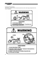
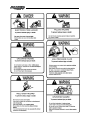
1
Operator and Parts Manual
Quick-Tach Grapple
Model C2000
012011
P3941
Table of Contents
Introduction..................................................................................................................................4
Safety.............................................................................................................................................5
• Safety.................................................................................................................................5
• General Safety...................................................................................................................6
• Start-up Safety..................................................................................................................6
• Operation Safety...............................................................................................................6
• Transport Safety................................................................................................................7
• Service and Maintenance Safety.....................................................................................7
• Storage Safety...................................................................................................................7
• Safety Signs......................................................................................................................8
• Safety Sign Installation....................................................................................................8
Mounting.......................................................................................................................................9
Assembly.....................................................................................................................................10
Parts............................................................................................................................................. 11
Grapple Hydraulic Kits...............................................................................................................12
Recommended Mounting Dimensions.....................................................................................12
• Standard Buckets............................................................................................................12
• 85" Manure Bucket..........................................................................................................13
Clamp and Cable Information....................................................................................................13
Grapple Removal/Attachment..................................................................................................14
Troubleshooting..........................................................................................................................15
Important Precautions...............................................................................................................16
Hydraulic Cylinder Assembly.....................................................................................................18
Warranty......................................................................................................................................20
Manufacturer’s statement: for technical reasons Buhler Industries Inc. reserves the right to modify
machinery design and specifications provided herein without any preliminary notice.
Information provided herein is of descriptive nature. Performance quality may depend on soil fertility,
applied agricultural techniques, weather conditions and other factors.
3
Introduction
Allied builds rugged attachments for all your commercial needs. Whether you need a skid steer or
tractor configuration, Allied makes all large jobs easier. Products range from commercial grade
snow blades to hay handling forks and grapples.
Attachments are coated with a three-part paint process to ensure many years of maintenance free
service. Allied loader attachments can be fixated to any loader or skid steer model currently on the
market. Simplicity and ease of use have been built into Allied for many years. Join in the tradition
of quality Allied products and have them working for your operation today.
Keep this manual handy for frequent reference. All new operators or owners must review the
manual before using the equipment and at least annually thereafter. Contact your Allied Dealer
if you need assistance, information, or additional copies of the manual. Visit our website at
www.buhlerindustries.com for a complete list of dealers in your area.
The directions left, right, front and rear, as mentioned throughout this manual, are as seen facing
in the direction of travel of the implement.
4
Safety
Safety Instructions
Remember, YOU are the key to safety. Good safety practices not only protect you, but also the
people around you. Make these practices a working part of your safety program. Be certain that
everyone operating this equipment is familiar with the recommended operating and maintenance
procedures and follows all the safety precautions. Most accidents can be prevented. Do not risk
injury or death by ignoring good safety practices.
The alert symbol is used throughout this manual. It indicates attention is required and identifies
hazards. Follow the recommended precautions.
The safety alert symbol means…
ATTENTION! BECOME ALERT! YOUR SAFETY IS INVOLVED!
Caution
The caution symbol indicates a potentially hazardous situation
that, if not avoided, may result in minor or moderate injury. It
may also be used to alert against unsafe practices.
Warning
The Warning Symbol indicates a potentially hazardous situation
that, if not avoided, could result in death or serious injury, and
includes hazards that are exposed when guards are removed. It
may also be used to alert against unsafe practices.
Danger
The Danger Symbol indicates an imminently hazardous situation
that, if not avoided will result in death or serious injury. This
signal word is to be limited to the most extreme situations,
typically for machine components that, for functional purposes,
cannot be guarded.
5
General Safety Instructions
•
•
•
•
•
•
•
•
•
Have a first-aid kit available for use and know how to use it.
Have a fire extinguisher available, stored in a highly visible location, and know how to use it.
Wear appropriate protective gear. This list may include but is not limited to:
-- hard hat
-- protective shoes with slip resistant soles
-- protective glasses or goggles
-- heavy gloves
-- wet weather gear
-- hearing protection
-- respirator or filter mask
Read and understand the Operator’s Manual and all safety signs before operating, servicing,
adjusting, repairing, or unplugging the equipment.
Do not attempt any unauthorized modifications to your Allied product as this could affect
function or safety, and could affect the life of the equipment.
Inspect and clean the working area before operating.
Keep hands, feet, clothing, and hair away from moving parts.
Ensure bystanders are clear of the area before operating.
Improper use of the loader and tractor can cause serious injury or death.
Start-Up Safety
•
•
Do not let inexperienced operators or children run this equipment.
Place all tractor and machine controls in neutral before starting.
Operation Safety
•
•
•
•
•
•
•
•
•
•
•
6
Do not permit riders.
Do not wear loose fitting clothing during operation.
Operate the loader while seated in the tractor seat only.
Never leave the tractor unattended while the attachment is raised. Always lower the
attachment to ground and shut the tractor off before leaving the tractor seat.
Never work beneath a raised loader unless it is securely supported. The control lever can be
moved or a hydraulic leak could cause the loader to drop resulting in serious injury or death.
Refer to the Lift Lock Instructions Decal for proper use of the lift locks.
Prior to use, check to ensure the attachment is properly locked to the quick-tach. Verify from
tractor seat by lowering the attachment to ground and retracting the lift cylinders.
Never operate the loader with frayed or damaged hoses or leaking fittings. A burst could
cause the loader to drop suddenly and result in serious injury or death and cause damage to
the loader or tractor.
Keep tractor on solid ground. Loose fill, rocks and holes can be dangerous for loader
operation and movement.
A pivoting front axle acts like a three-wheeled tractor until the stops hit the axle.
Space rear tires as recommended by the tractor manufacturer. Maximize width for high lift
applications and uneven terrain.
Add rear ballast as required to ensure 25% of gross vehicle weight is transferred to the rear
axle. Loader, attachment and payload must be included as weight.
•
Do not raise attachment to extreme heights while tractor in on an incline. Be alert for terrain
changes and adjust accordingly. Keep attachment at low travel height, no more than one
foot, as long as possible.
Transport Safety
•
•
•
•
•
•
•
Review Transport Safety instructions in tractor manual before moving.
Check with local authorities regarding transport on public roads. Obey all applicable laws
and regulations.
Make sure the SMV (Slow Moving Vehicle) emblem and all the lights and reflectors that are
required by the local highway and transport authorities are in place, are clean, and can be
seen clearly by all overtaking and oncoming traffic.
Never have the equipment in operation during transport.
Always travel at a safe speed.
Allow for attachment and loader length when turning.
The tractor must be equipped with an approved Roll Over Protection Structure (ROPS) and
safety belts.
Service and Maintenance Safety
•
•
•
•
•
•
•
•
Stop engine, set brake, remove ignition key, and wait for all moving parts to stop before
servicing, adjusting, repairing, or unplugging.
Support the equipment with blocks or safety stands before working beneath it.
Follow good shop practices including:
-- keep service area clean and dry
-- be sure electrical outlets and tools are properly grounded
-- use adequate light for the job.
Use only tools, jacks, and hoists of sufficient capacity for the job.
Replace and secure all shields removed during servicing before operating.
Use heavy leather gloves to handle sharp objects.
Check hydraulics regularly for leaks. Use cardboard to look for leaks, and use hand and eye
protection.
Relieve pressure on hydraulic system before repairing or adjusting.
Storage Safety
•
•
•
Store the unit in an area away from human activity.
Do not permit children to play on or around the stored machine.
Support the frame on stands and blocks to provide a secure base.
7
Safety Signs
•
•
Keep all safety signs clean and legible and replace any that are damaged or missing.
When original parts are replaced, any safety signs affixed to those parts should be replaced
as well. Replacement safety signs are available from your local dealer.
Installation
•
•
•
8
To install safety signs, ensure the installation area is clean and dry. Decide on the exact
position before you remove the backing paper. Remove the smallest portion of the split
backing paper and align over the specified area. Carefully press in place.
Slowly peel back the remaining paper and smooth the remaining portion in place. Small air
pockets can be pierced with a pin and smoothed out.
Replace safety signs immediately should they become damaged, torn or illegible. Obtain
replacements from your authorized dealer using the part numbers shown.
Mounting
Please read and understand the following instructions before mounting.
1.
Refer to the recommended mounting dimensions for mounting hole locations on various
loader/bucket combinations. Drill twelve 0.56" diameter holes as indicated. Drill two 0.44"
diameter holes into the top of the bucket for the hose clamps. Proper position of the hose
clamps will eliminate interference between the hoses and mechanical linkages during loader
operation. Specific grapple buckets equipped with backing plates and prepunched holes are
also available. See price pages or contact local dealer.
2. Install the quick-tach brackets (item 7, 31), grapple boots (item 6), and backing plates (item 8,
32) onto the bucket with carriage bolts (item 24) and steel lock nuts (item 27). Finger tighten
hardware. NOTE: backing plates must be adapted for all ‘X’ Series buckets as shown.
3. Install uprights (item 4) into boots and brackets with quick-tach pins (item 9) and hair pin clips
(item10). Assemble mainframes (item 3) into the uprights using pins (item 13), bolts (item 23)
and nylon lock nuts (item 26).
4. Support mainframes and install hydraulic cylinders using pins (item 14), bolts (item 23) and
nylon lock nuts (item 26).
5. Assemble elbows (item 17), 44" hoses (item 16), tees (item 18), 72" hoses (item 15) and
hydraulic tips (item 19). Connect hoses to grapple hydraulic kit. Clamp hoses to the top of the
bucket using clamps (item 36), plates (item 35), bolts (item 37), and nuts (item 34). Tyraps
(item 20) have been provided to group hoses. Ensure sufficient clearance during operation.
6. Using bolts (item 22) and steel lock nuts (item 25), assemble the outer tooth weldments
(item 1) and the cross tube (item 2) to the mainframes as shown. Torque bolts to 150 ft-lbs.
7.
Adjust the quick-tach bracket and boot locations such that the quick-tach pins can be removed
and installed by hand. Slots have been provided for adjustment. Torque bolts to 75 ft-lbs.
8. Attach remaining teeth (item1) to the cross tube (item 2) using u-bolts (item 21) and steel lock
nuts (item 25). Position teeth as required. Avoid interferences with bucket tines (if equipped).
Torque bolts to 150 ft-lbs.
9. Attach the cable (item 11) to the mainframe using cable clamps (item 12). See clamp and cable
information for proper assembly.
10. Apply grease to all pivots as indicated by grease symbols.
11. Completely raise and lower the loader and fully dump and rollback the bucket while the
grapple remains in an opened and closed position. Ensure that the loader and grapple operate
properly. Verify that all hoses are routed and tied appropriately to avoid rubbing or pinching
during operation.
9
Assembly
NOTE:
1.
Item 20, ty-raps, are to be used to hold
hoses together.
2. Item 29, dust caps, are to be attached to the
male hydraulic tip.
3. Item 30, cylinder decals, are to be placed
on the tube weldments.
4. Standard bucket assembly shown.
10
Parts
Part No.
1
114408
Tooth Weldment
5
5
2
114467
Cross Tube 84"
1
1
114793
Cross Tube 96"
24755
Mainframe Weldment
2
2
3
Description
Standard
Manure
Bucket
Bucket
C2000 (84") C2062 (84")
Item
4
24756
Upright Weldment
2
2
5
24875
Cylinder Assembly 2.5 x 7.25
2
2
6
114723
Grapple Boot Weldment
2
2
7
114427
Quick-Tach Weldment
2
8
115551
Backing Plate
2
9
114741
Quick-Tach Pin Weldment
2
2
10
12779
Hair Pin Clip
2
2
11
114880
Cable 0.250 dia GAC 7 x 19
1
1
12
961658
Clamp Cable 1/4"
4
4
13
104719
Pin 1.00 dia x 6.00 long
2
2
14
113797
Pin 1.00 dia x 5.00 long
4
4
15
811579
3/8 x 72 Hose 3/4 MORB x 3/4 SWFJIC
2
2
16
115635
3/8 x 50 Hose 3/4 SWFJIC x 3/4 SWFJIC
4
4
17
811414
Elbow 90 3/4 MORB x 3/4 MJIC
4
4
18
812069
Tee 3/4 MJIC
2
2
19
812841
Coupler Male 0.75 ORB
2
2
20
812075
Ty-Rap 13-5/8" long (TY-27M)
4
4
21
112988
U-Bolt 0.63 x 4.06 x 5.25
6
6
22
812087
Bolt Hex 0.625nc x 6.00 gr5 pl
8
8
23
810640
Bolt Hex 0.313nc x 2.00 gr5 pl
6
6
24
812217
Bolt Carriage 0.500nc x 1.50 gr5 pl
12
12
25
812482
Nut Lock (Steel) 0.625nc grB pl
20
20
26
84541
Nut Lock (Nylon) 0.313nc grB pl
6
6
27
812364
Nut Lock (Steel) 0.500nc grB pl
12
12
28
815034
Allied by Farm King Decal
2
2
29
813305
Dust Cap – Black
2
2
30
22370
Hydraulic Cylinder Decal
2
2
31
114900
Quick-Tach Weldment (manure bucket)
2
32
114904
Backing Plate (manure bucket)
2
33
114430
Bushing 1.0 I.D. x 1.25 O.D. x 0.88 LG
4
4
34
84217
Nut Wing 0.375nc gr2 pl
2
2
35
113923
Hose Clamp Plate
2
2
36
113843
3/8 Hose Clamp (Poly)
2
2
37
813471
Wing Screw 0.375nc x 2.00 gr5 pl
2
2
Tine
Kit
X1999
1
2
4
11
Grapple Hydraulic Kits
Part No.
NOTE:
Description
C9936
495-895 REG/HSL
C1964
595-795 TSL
C1965
895 TSL
C2246
2595/2596/2795
Grapple hydraulic kits are sold separately. Kits
include hydraulic tubes, which are mounted
along existing loader hydraulic tubes for
grapple operation, hydraulic couplers and
hardware.
Recommended Mounting Dimensions
Standard Buckets
Loader Model
495/595/695/2495/2595
Bucket Series
795/2795/895/2895/995
‘X’ Series
Any
‘X’ or ‘B’ Series
‘B’ Series
Bucket Width
72"*
84"
72"*
84"
96"*/102"*
84"
96"*/102"*
A
2.25
2.25
2.38
2.38
2.38
2.38
2.38
B
4.13
4.13
4.25
4.25
4.25
4.25
4.25
C
9.50
9.50
12.56
12.56
12.56
12.56
12.56
D
13.00
13.00
16.06
16.06
16.06
16.06
16.06
E
57.63
65.63
57.63
65.63
69.63
65.63
69.63
F
63.75
71.75
63.75
71.75
75.75
71.75
75.75
G
69.88
77.88
69.88
77.88
81.88
77.88
81.88
NOTE:
1.
The above table lists the recommended hole spacing for all Allied loaders from 495 to 995
(including Reg/S/HSL/TSL) with standard buckets. If required the grapple may be located to suit
specific applications. Verify all clearances between the grapple and the loader.
2. When used with Allied standard buckets, dimensions A, B, C, and D must be kept as specified
in the table.
3. The minimum cross tube length (84") will extend 6" past both ends of the 72" buckets.
4. Grapple buckets (B459584, B479584, B479596, B489596, B4259584 and B4279596) come
equipped with backing plates and pre-punched holes.
*This mounting combination may not allow the bucket quick-tach pin to be placed in the quick-tach storage location. This
does not affect the ability to install or remove the quick-tach bucket.
12
85" Manure Bucket
NOTE:
1.
Recommended grapple spacing for an 85” manure bucket. If required the grapple may be
located to suit specific applications. Verify all clearances between the grapple and the loader.
2. Grapple cannot be mounted as shown on 49" and 67" manure buckets. Mount inside quick-tach
brackets if desired.
Clamp and Cable Information
NOTE:
1.
Nominal breaking strength of 1/4" 7 x 9 Galvanized Aircraft Cable: 7000 lbs.
2. Do not reinstall used clamps.
3. Re-tighten nuts periodically after cable has been in use. Torque to 15 ft-lbs.
4. Do not lubricate threads.
5. Never use clips to make direct end-to-end joints of rope.
6. Saddle of clamps must always be installed at long (live) end of cable.
13
Grapple Removal/Attachment
NOTE:
1.
With grapple open, approach two bales placed end to end (Figure 1).
2. Position grapple over bales as shown (Figure 2).
3. Remove both quick attach pins.
4. Back out slowly. Grapple will slide out of mount bracket weldments (Figure 3.)
5. Disconnect hoses.
6. To reattach, reverse process
14
Troubleshooting
Problem
Cause
Quick couplers leaking
Hydraulic oil to heavy
Change or replace filter
Oil filter plugged
Loader slow and/or will not dump
Remedy
Check connections and compatibility or
replace
Clean or replace filter
Hydraulic pump worn
Repair or replace pump
Oil line restricted or leaking
Check all hoses and tubes for leaks,
damage or restrictions. Replace
damaged or restricted hoses or tube
lines.
Control valve does not shift properly
Inspect, clean, repair or replace valve
Air in hydraulic system
Cycle lift cylinders and bucket cylinders
several times to free system of air
Cylinder leaks internally
Replace seals
Faulty valve
Repair or replace valve
Air leak in pump inlet line.
Check, tighten or replace inlet line
Loader chatters or vibrates when
raising and lowering
Air in hydraulic system
Cycle lift cylinders and bucket
cylinders.
Excessive movement at pivots
Oil level too low
Add oil as required
Worn bushings and/or pins
Replace bushings and/or pins
Inlet line restricted or leaking.
Check for air leaks, restrictions or
collapsed hose. Tighten or replace
hose. Clean filter if necessary.
Oil level too low
Add oil as required
Pump worn or damaged
Repair or replace pump
Improper hydraulic pump operation
Repair or replace pump
Load is greater than boom lift capacity
Check loader specifications
Internal boom cylinder leakage
Replace any worn parts and install a
seal repair kit
Improper hydraulic valve operation
Repair or replace valve
Worn control valve
Have authorized dealer replace seals
Worn cylinder piston seals
Have authorized dealer replace seals
Excessive wear on bottom of
bucket and wear pads
Float position not used while
operating loader
Use float position provided on valve.
Hydraulic cylinders. Inoperative
Hose from control valve improperly
connected
Refer to plumbing diagrams.
Tractor control valve relief stuck open
See your tractor manual for proper
adjustment or loader dealer for loader
valve. (3000 PSI is maximum pressure
relief setting recommended.)
Hydraulic control valve set too low.
Adjust valve in accordance with
manual.
Loaders lift and bucket tilt controls do
not work according to decal
Hoses improperly connected.
Replace relief valve with closed center
plug and plug the power beyond
adapter on valve.
Valve noise and/or hot
Open center control valve on closed
center tractor
Replace relief valve with closed center
plug and plug the power beyond
adapter on valve.
Tractor loads/pump squeals.
Closed center control valve on open
center tractor
Install open center plug on optional
valve. Replace closed center plug with
relief and install short plug in place of
power beyond adapter
Pump noisy
Insufficient lift capacity
Slow leak down
Pump operating continually on
closed center tractor hydraulic
system
15
Important Precautions
The following pictorials indicate important precautions to be used during the operation of the
loader and grapple.
16
17
Hydraulic Cylinder Assembly
24758
24875
2.00"
2.50"
Diameter
Cylinder Assembly
7.25"
7.25"
Length of Stroke
16.50"
16.50"
Retracted Length
23.75"
23.75"
Extended Length
X1348
X1110
Seal Kit No.
1.25"
1.50"
Shaft Diameter
Item
Part No.
Part No.
Description
1
24516
24540
Head Plate
2
114411
24874
Shaft Weldment
3
24757
24873
Cylinder Tube Weldment
4
114520
113217
Piston Half (wide)
5
114521
113216
Piston Half (narrow)
6
812655
813407
Self-Locking Nut
7
114430
114430
Shaft Bushing
Caution
18
NOTE:
1.
Cylinders may vary in appearance.
2. All cylinder seals are contained in
corresponding seal kit.
3. Cylinder assembly no. 24875 (2.5 Dia.)
supplied as standard.
Maximum pressure - 3000 psi
Warranty
Allied by Farm King Limited Warranty
This document limits your warranty rights.
Base Limited Warranty
Buhler Industries Inc. provides this warranty only to original retail purchasers of its product.
Buhler Industries Inc. warrants to such purchasers that all Buhler Industries Inc. manufactured
parts and components used and serviced as provided for in the Operator’s Manual shall be free
from defects in materials and workmanship for a period following delivery to the original retail
purchaser of 12 months (80 days for commercial applications). This limited warranty applies only
to those parts and components manufactured by Buhler Industries Inc. Parts and components
manufactured by others are subject to their manufacturer’s warranties, if any.
Buhler Industries Inc. will fulfill this limited warranty by, at its option, repairing or replacing
any covered part that is defective or is the result of improper workmanship, provided that the
part is returned to Buhler Industries Inc. within thirty (30) days of the date that such defect or
improper workmanship is, or should have been, discovered. Buhler Industries Inc. reserves the
right to either inspect the product at the buyer’s location or have it returned to the factory for
inspection. Parts must be returned through the selling representative and the buyer must prepay
transportation charges.
Buhler Industries Inc. will not be responsible for repairs or replacements that are necessitated,
in whole or part, by the use of parts not manufactured by or obtained from Buhler Industries Inc.
Under no circumstances are component parts warranted against normal wear and tear. There
is no warranty on product pump seals, product pump bearings, rubber product hoses, pressure
gauges, or other components that require replacement as part of normal maintenance. Also:
Buckets and Bucket Tines carry no warranty, Bent Spears carry no warranty, Snowblower Fan
Shafts carry no warranty, Mower Blades carry no warranty, Portable Auger Parts Have Two (2)
Year Warranty, Loader Parts Have Two (2) Year Warranty. The purchaser is solely responsible for
determining suitability of goods sold. This warranty is expressly in lieu of all other warranties
expressed or implied. Buhler Industries Inc. will in no event be liable for any incidental or
consequential damages whatsoever. Nor for any sum in excess of the price received for the
goods for which liability is claimed.
Repair Parts Limited Warranty
Buhler Industries Inc. warrants Farm King replacement parts purchased after the expiration of the
Buhler Industries Inc. Limited Warranty, and used and serviced as provided for in the Operator’s
Manual, to be free from defects in materials or workmanship for a period of thirty (30) days
from the invoice date for the parts. Buhler Industries Inc. will fulfill this limited warranty by, at
its option, repairing or replacing any covered part that is defective or is the result of improper
workmanship, provided that the part is returned to Buhler Industries Inc. within thirty (30) days
of the date that such defect or improper workmanship is, or should have been, discovered. Such
parts must be shipped to Buhler Industries Inc. at the purchaser’s expense.
What is Not Covered
Under no circumstances does this limited warranty cover any components or parts that have
been subject to the following: negligence; alteration or modification not approved by Buhler
Industries Inc.; misuse; improper storage; lack of reasonable and proper maintenance, service,
or repair; normal wear; damage from failure to follow operating instructions; accident; and/
or repairs that have been made with parts other than those manufactured, supplied, and or
authorized by Buhler Industries Inc.
20
Warranty
Authorized Dealer and Labor Costs
Repairs eligible for labor under this limited warranty must be made by Buhler Industries Inc. or an
authorized Farm King dealer. Buhler Industries Inc. retains the exclusive discretion to determine
whether it will pay labor costs for warranty repairs or replacements, and the amount of such
costs that it will pay and the time in which the repairs will be made. If Buhler Industries Inc.
determines that it will pay labor costs for warranty work, it will do so by issuing a credit to the
dealer’s or distributor’s account. Buhler Industries Inc. will not approve or pay invoices sent for
repairs that Buhler Industries Inc. has not previously approved. Warranty service does not extend
the original term of this limited warranty.
Warranty Requirements
To be covered by warranty, each Farm King new product must be registered with Buhler
Industries Inc. within thirty (30) days of delivery to original retail purchaser. If the customer
decides to purchase replacement components before the warranty disposition of such
components is determined, Buhler Industries Inc. will bill the customer for such components and
then credit the replacement invoice for those components later determined to be covered by this
limited warranty. Any such replacement components that are determined not be covered by this
limited warranty will be subject to the terms of the invoice and shall be paid for by the purchaser.
Warranty Claims:
Warranty requests must be prepared on Buhler Industries Inc. Warranty Claim Forms with all
requested information properly completed. Warranty Claims must be submitted within a thirty
(30) day period from date of failure repair.
Warranty Labor:
Any labor subject to warranty must be authorized by Buhler Industries Inc. The labor rate for
replacing defective parts, where applicable, will be credited at 100% of the dealer’s posted shop
rate. Defective parts will receive an extra 10% discount to assist with freight or other incidental
costs.
Exclusive Effect of Warranty and Limitation of Liability
TO THE EXTENT PERMITTED BY LAW, Buhler Industries Inc. DISCLAIMS ANY
WARRANTIES, REPRESENTATIONS, OR PROMISES, EXPRESS OR IMPLIED, AS TO THE QUALITY,
PERFORMANCE, OR FREEDOM FROM DEFECT OF THE COMPONENTS AND PARTS COVERED BY
THIS WARRANTY AND NOT SPECIFICALLY PROVIDED FOR HEREIN.
TO THE EXTENT PERMITTED BY LAW, Buhler Industries Inc. DISCLAIMS ANY IMPLIED
WARRANTIES OF MERCHANTABILITY AND FITNESS FOR A PARTICULAR PURPOSE ON ITS
PRODUCTS COVERED HEREIN, AND DISCLAIMS ANY RELIANCE BY THE PURCHASER ON
Buhler Industries Inc.’S SKILL OR JUDGMENT TO SELECT OR FURNISH GOODS FOR ANY
PARTICULAR PURPOSE. THE PURCHASER’S ONLY AND EXCLUSIVE REMEDIES IN CONNECTION
WITH THE BREACH OR PERFORMANCE OF ANY WARRANTY ON ProductS manufactured
by Buhler Industries Inc. ARE THOSE SET FORTH HEREIN. IN NO EVENT SHALL Buhler
Industries Inc. BE LIABLE FOR INCIDENTAL OR CONSEQUENTIAL DAMAGES (INCLUDING,
BY WAY OF EXAMPLE ONLY AND NOT LIMITATION, LOSS OF CROPS, LOSS OF PROFITS OR
REVENUE, OTHER COMMERCIAL LOSSES, INCONVENIENCE, OR COST OF REPLACEMENT
OF RENTAL EQUIPMENT). IN NO EVENT SHALL FARM KING’S CONTRACT OR WARRANTY
LIABILITY EXCEED THE PURCHASE PRICE OF THE PRODUCT.
21
Warranty
(Note that some provinces or states do not allow limitations on how long an implied warranty
lasts or the exclusion or limitation of incidental or consequential damages, so the above
limitations and exclusion may not apply to you.) This warranty gives you specific legal rights and
you may also have other rights, which vary from province to province or state to state.
Buhler Industries Inc. neither assumes nor authorizes any person or entity, including its selling
representatives, to assume any other obligations or liability in connections with the sale of
covered equipment, or to make any other warranties, representations, or promises, express or
implied, as to the quality, performance, or freedom from defect of the components and parts
covered herein. No one is authorized to alter, modify, or enlarge this limited warranty, or its
exclusions, limitations and reservations.
Corrections of defects and improper workmanship in the manner, and for the applicable time
periods, provided for herein shall constitute fulfillment of all responsibilities of Buhler Industries
Inc. to the purchaser, and Buhler Industries Inc. shall not be liable in negligence, contract, or on
any other basis with respect to the subject equipment.
This limited warranty is subject to any existing conditions of supply which may directly affect
Buhler Industries Inc.’s ability to obtain materials or manufacture replacement parts.
Buhler Industries Inc. reserves the right to make improvements in design or changes in
specifications to its products at anytime, without incurring any obligation to owners of units
previously sold.
Government Legislation:
Warranty terms and conditions are subject to provincial or state legislation.
Important Note: This warranty does not apply to rentals.
22
www.farm-king.com
1330 43rd Street NW
Fargo, ND USA 58102
Ph.: 701.282.7014 | Fax: 701.282.5865
Toll Free: 888.524.1004
E-mail: [email protected]
www.farm-king.com
Equipment shown is subject to change without notice.
©2010 Buhler Trading Inc. Printed in USA. TSX:BUI
a division of Buhler Industries Inc.