1
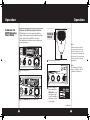
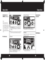
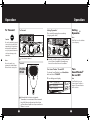
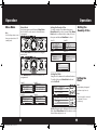
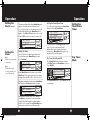
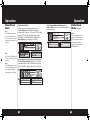
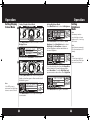
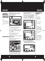
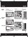
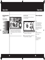
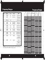
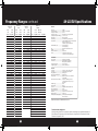
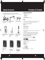
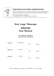
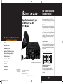
29 LX EU
Operating Instructions for your
Cobra 29 LX EU
CB Radio
The Cobra line of quality products includes:
Downloaded from www.cbradio.nl
Our Thanks to You and
Customer Service
Thank you for purchasing the Cobra 29 LX EU CB
Radio Transceiver. Properly used, this Cobra product
will give you many years of reliable service.
NOTICE!
Before using this transceiver, please check that the
radio has been programmed on the frequency band
specifications and operating modes allowed by the
regulations valid in the country where the product is
used. If not, please proceed to modify the frequency
band programming, as described in this owner’s
manual page 17. This transceiver is programmed at
the factory on the EU frequency band (40 CH AM
1W/40 CH FM 4W).
Customer Assistance
Radar/Laser Detectors
Should you encounter any problems with this
product, or not understand its many features, please
refer to this owner’s manual. If you require further
assistance after reading this manual, please contact
your local dealer.
Safety Alert® Traffic Warning Systems
This equipment is intended for use in:
CB Radios
microTALK® Radios
Truck-Specific Navigation Systems
This equipment is intended for use in:
HighGear® Accessories
CobraMarine VHF Radios
Power Inverters
U.S. Patent Nos. D625279, D630202 & D630625
LED Lights
Jumpstarters
Accessories
For more information or to
order any of our products,
please visit our website:
www.cobra.com
©2011 Cobra Electronics Corporation
Printed in China
Part No. 480-703-P Version D
Nothing Comes Close to a Cobra®
29LXEU_MANL_ENG_vD.indd 40-42
AT
BA
BE
BG
CH
CY
CZ
DE
DK
EE
ES
FI
FR
GB
GR
HR
HU
IE
IS
IT
LT
LV
LU
MK
MT
RU
NL
SE
NO
SI
PL
SK
PT
TR
RO
UA
RS
Countries of use
For Warranty, Product Service and
Accessory Information
Please contact your local dealer or distributor.
See the enclosed leaflet, which provides contact
information for the Cobra international
distributors.
A1
1/11/12 10:09 AM
Included in this Package
Controls and Indicators
29 LX EU Fuses
Front Side
2
3
19
cb tranceiver
4
1
17
NB /ANL
2
NB/ANL SWR 1.5
ANL
S/ RF
S/RF
SWR
CAL
OFF
CAL
SQ
SCAN
TX
3
18
ESC
5 79
+30dB
DYNAMIKE
M
EN
U SH EN
U P
TE
MEM
R
RF GAIN
MIN
MIN
DELTA TUNE
MAX
T BACK
2
NB/ANL SWR 1.5
ANL
DIM
SIG 1
16
12
15 14
NB /ANL
CH 9/
19
MEM SCAN
RX
RF
SWR /CAL
VOL
3
SWR
CAL
S/ RF
S/RF
SWR
CAL
1
OFF
3
5 79
+30dB
DYNAMIKE
M
EN
U SH EN
U P
TE
13
MEM
RF GAIN
DELTA TUNE
MAX
MIN
5
4
MEM SCAN
DIM
ESC
R
MIN
2
6
7
T BACK
2. Microphone
11
10
SWR
CAL
OFF
8
9
3
1. CB Transceiver
CH 9/
19
SCAN
TX
RX
SIG 1
SQ
OFF
CAL
RF
SWR /CAL
VOL
3
5
3. Transceiver Bracket
20
21
4. Microphone Bracket
FCC ID:BBO3K229LTD
COBRA
5. Operating Manual
6. DC Power Cord
S-MTR EXT.SP.
+ POWER –
6
22
A2
29LXEU_MANL_ENG_vD.indd 43-45
ANT
MADE IN CHINA
23
A3
1. 4-PinMicrophone
Connector
2. PowerOn/Off,Volume
3. Squelch
4. Dynamike
5. Menu/Enter/Channel
Selector
6. RFGain
7. DeltaTune
8. TalkBackControl
9. SWRCalibration
10. Dim/EscapeButton
11. Channel9/Channel19 Button
12. Scan/MemoryScan
13. AM/FMButton
14. LCDDisplay
15. RX(Receive)/TX(Transmit),
Indicators
16. SignalStrengthMeter
17. NB/ANLButton
18. S/RFSWRCALButton
19.1Microphone
Back Side
20. S-MeterJack
21. ExternalSpeakerJack
22 AntennaConnector
23. PowerJack
Replacing the
In-Line Fuse
IN-LINE
FUSE HOLDER
2A, 250V FUSE
IN-LINE
FUSE HOLDER
Note
Theradioisprotectedwitha2
To replace the in-line fuse; push the ends of the holder
fusesystemintheeventthatthe together then turn counter-clockwise and pull the two
sections apart.
userdecidesnottousethe
cigarettelighterplug.
IN-LINE
FUSE HOLDER
Caution
Forcontinuedprotection
againstfirehazard,replacewith
sametype2A,250Vfuses.
Replacing the
Fuse in the CLP
Note
Thereisaretainingspringin
theCLPusedfortension
connectivity.
IN-LINE
FUSE HOLDER
FUSE
IN-LINE
FUSE HOLDER
To replace the fuse in the cigarette light plug (CLP),
rotate the metal tip of the CLP to access the fuse.
Be sure not to lose the retaining spring within
the holder.
CIGARETTE
LIGHTER PLUG
RETAINING
SPRING
METAL TIP
2A, 250V FUSE
40
1/11/12 10:09 AM
How to Use Your Cobra 29 LX EU
Contents
Our Thanks to You & Customer Service ...........................................A1
Included in this Package .........................................................................A2
Controls & Indicators................................................................................A3
Installation
Location & Mounting/Connection ..................................................2
Antennas
CB Antenna & Marine Installation ...................................................6
Ignition Noise Interference....................................................................7
Operating Your 29 LX EU
Turning On Your CB.............................................................................. 8
Setting Channel Selector .................................................................... 9
Calibrate For SWR (Standing Wave Ratio) .................................... 10
To Receive ................................................................................................ 12
Selecting a Channel .............................................................................. 13
S/RF-Meter ............................................................................................... 13
To Transmit .............................................................................................. 14
Setting Dynamike® ............................................................................... 15
Turn SoundTracker® On and Off ...................................................... 15
Menu Mode ............................................................................................. 16
Setting the Country of Use ................................................................ 17
Setting the Clock ................................................................................... 17
Setting the Alarm .................................................................................. 18
Setting the Count Down Timer ........................................................ 19
Key Tones Mode .................................................................................... 19
Radio Check Mode ................................................................................ 20
Setting Display Colour Mode ............................................................ 22
Setting Brightness Mode .................................................................... 23
Setting Contrast Mode ........................................................................ 24
Software Version/Factory Settings ................................................. 25
NB-ANL/Off (Noise Blanker/Automatic.......................................... 26
Noise Limiter Switch)
RF Gain Control ...................................................................................... 26
Program Memory Channels............................................................... 27
Scan CB Channels .................................................................................. 28
Scan Memory Channels ...................................................................... 28
Dimmer Control ..................................................................................... 28
Setting Squelch ...................................................................................... 29
External Speaker .................................................................................... 31
Home And Office Set-Up .................................................................... 32
Temporary Mobile Set-Up .................................................................. 33
Frequency Ranges ..................................................................................... 34
29 LX EU Specifications ...........................................................................37
Optional Accessories ................................................................................ 38
Declaration of Conformity ..................................................................... 39
29 LX EU Fuses ............................................................................................ 40
Features of This Product
• AM/FM1W/4WMulti-Country
ProgrammableTransceiver
• Selectable4-ColourLCDDisplay
• Scan
• MemoryChannels/Scan
• ChannelFrequencyRead-Out
• RadioCheckDiagnostic
• Clock/Timer/Alarm
• Heavy-DutyDynamic
Microphone
• 1/4WAM/4WFMRFPowerOutput
• SoundTracker®NoiseReduction
• SWRCalibrationMeter
• InstantChannel19and9
• FrontPanel4-PinMicrophone
Connector
• SwitchableAutomaticNoise
Limiter&NoiseBlanker
• AdjustableDynamikeBoost
• TactileControls
• ProgrammableDimmerControl
• RFGain
• S-MeterJack
1
29LXEU_MANL_ENG_vD.indd 1
1/11/12 10:09 AM
Installation
Installation
Location
Location
Plan location of transceiver and microphone
bracket before starting the installation.
S-MTR EXT.SP.
+ POWER –
Select a location that is convenient for operation,
yet does not interfere with the driver or passenger.
The transceiver is usually mounted to the underside of the dash with the microphone bracket
beside it.
Mounting and
Connection
Mounting and Connection
1
Note
Thetransceiverisheldinthe
universalmountingbracketby
twothumbscrewswhichallow
foradjustmentataconvenient
angle.
Hold the radio with the mounting bracket in
the exact desired location. If there is no interference, remove the bracket and use it as a
template to mark the location for the mounting screws.
3
Connect the antenna cable plug to the receptacle marked “ANT” on the back of the unit.
Thebracketincludestwoself-
tappingscrewsandstarwashers.Themountingmustbe
mechanicallystrong,convenientlylocated.
2
Drill the holes and secure the bracket.
2
29LXEU_MANL_ENG_vD.indd 2-3
continued
3
1/11/12 10:09 AM
Installation
Installation
Note
12V Dashboard
Connection
Radiois12VDCandcanbe
connectedviavehicle’scigarette
lighterplug.
S-MTR EXT.SP.
+ POWER –
Before installing the CB radio
to the battery or fuse block,
visually check the vehicle’s
battery connection to determine which terminal, positive
or negative, is earthed (positive is the larger of the two) to
the engine block (or chassis).
A negatively earthed vehicle
has its negative lead grounded to the chassis.
Direct Wiring
6
Plug power cable into back of unit marked
“Power”. Be sure to observe polarity markings.
7
Mount the microphone
bracket on either side
of the unit (driver’s left)
using two screws supplied. Bracket should be
placed under the dash
so microphone is readily
accessible.
Note
Connectingtoanaccessoryfuse
preventstheunitfrombeingleft
onaccidentally,andalsopermitsoperatingtheunitwithout
runningtheengine.
Note
Note
Inpositiveearthvehiclesthered
wiregoestothechassisandthe
blackwireisconnectedtothe
ignitionswitch.
4
29LXEU_MANL_ENG_vD.indd 4-5
4
In a negative earthed vehicle, connect the red
lead of the DC power cord to an accessory 12
volt fuse.
5
Connect the black lead to the negative side
of the vehicle. This is usually the chassis. Any
convenient location with a good electrical
contact (remove paint) may be used.
If microphone is not
connected, audio will not
be heard at speaker.
8
Attach the 4-pin microphone cable to
receptacle on front of unit and install unit
in bracket securely.
5
1/11/12 10:09 AM
Antennas
Ignition Noise Interference
CB Antenna
CB Antenna
Since the maximum allowable power output of
the transmitter is limited, the antenna is critical in
affecting transmission distance. Only a properly
matched antenna system will allow maximum
power output. Cobra loaded type antenna models
are highly recommended for most installations.
Note
Foroptimumperformancein
passengercarstheidealantennalocationisonthecentreof
theroof.Secondchoiceisonthe
centreoftheboot.
S-MTR EXT.SP.
+ POWER –
Note
Becausemanynewertrucks
featurefibreglassdoorskins,
theoutsidemirrormustbe
earthedtothechassisviaa
earthstrap,iftheantennais
mountedonthemirrorbracket.
1
A standard antenna connector is provided
on the transceiver for easy connection.
Note
Marine Installation
3-wayCombinationAntennas
arealsoavailable,whichallow
operationofallthreebands
(AM-FM&CB),usingasingle
antenna.However,thistype
ofantennausuallyresultsin
lessthannormaltransmitand
receiverangewhencompared
toastandard-type“Single
Band”CBantenna.
The transceiver will not operate at maximum
efficiency in a boat without a ground plate,
(unless it has a steel hull). Before attempting
installation , consult your dealer for information
regarding an adequate earthing system and prevention of electrolysis between fittings in the hull
and water.
6
29LXEU_MANL_ENG_vD.indd 6-7
Use of a mobile receiver at low signal levels is
normally limited by the presence of electrical
noise. The primary source of noise in automobiles is from the alternator and ignition system.
Typically, when signal level is adequate, the backearth noise does not present a serious problem.
Also, when extremely low level signals are being
received, the transceiver may be operated with
the vehicle’s engine turned off. The unit requires
very little current and therefore will not significantly discharge the vehicle’s battery.
Even though the Cobra 29 LX EU has an automatic noise limiter, in some installations ignition
interference may be high enough to make good
communications impossible. Many possibilities
exist and variations between vehicles require
different solutions. Consult your Cobra dealer or
a 2-way radio technician for help in locating the
source of a severe noise.
7
1/11/12 10:09 AM
Operation
Operation
Turning On
Turning On
Note
Beforeusingthistransceiver,
pleasecheckthattheradiohas
beenprogrammedonthe
frequencybandspecifications
andoperatingmodesallowed
bytheregulationsvalidinthe
countrywheretheproductis
used.Ifnot,pleaseproceedto
modifythefrequencyband
programming,asdescribedon
page17.Thistransceiverisprogrammedatthefactoryonthe
EUfrequencyband(40CHAM
1W/40CHFM4W).
NB/ANL
2
NB/ANL SWR 1.5
ANL
S/RF
S/RF
SWR
CAL
VOL
OFF
3
3
CAL
SQ
TX
RX
RF
SWR/CAL
1
Setting Channel
Selector
Setting Channel Selector
Make sure the power cord, antenna and microphone are connected to their proper connectors
before starting.
3
SIG 1
5 79
+30dB
DYNAMIKE
MIN
M
EN
U SH EN
U P
TE
MEM
R
RF GA
MIN
Select one of the channels and adjust
volume. The selected channel will be indicated by the readout directly above the channel
selector knob
Rotate the On/Off Volume knob clockwise to
turn unit on and adjust to a normal listening
level.
NB /ANL
2
NB/ANL SWR 1.5
ANL
S/RF
S/RF
SWR
CAL
OFF
CAL
SQ
SCAN
TX
CH 9/
19
MEM SCAN
RX
RF
SWR/CAL
VOL
3
DIM
3
SIG 1
ESC
5 79
+30dB
DYNAMIKE
M
EN
U SH EN
U P
TE
RF GAIN
MIN
MIN
2
8
29LXEU_MANL_ENG_vD.indd 8-9
MEM
R
DELTA TUNE
MAX
T BACK
SWR
CAL
OFF
Press the AM/FM button to change bands.
9
1/11/12 10:09 AM
Operation
Calibrate For
SWR (Standing
Wave Ratio)
Operation
Calibrate for SWR (Standing Wave Ratio)
PUSH &
HOLD
SWR calibration is done to properly adjust the
length of the antenna and to monitor the quality
of the coaxial cable and all RF connections.
This calibration is critical in order to achieve optimum performance.
Note
NB /ANL
2
SWR 1.5
S/ RF
3
RX
RF
3
SIG 1
SWR /CAL
VOL
SQ
5 79
+30dB
M
DYNAMIKE
EN
U SH EN
U P
TE
MEM
R
3
Pushandhold mic button.
NB /ANL
OFF
2
NB/ANL SWR 1.5
ANL
MIN
S/ RF
1
S/RF
SWR
CAL
Select channel 20.SWR/CAL
VOL
OFF
3
CAL
M
RF
SQ
SCAN
TX
29LXEU_MANL_ENG_vD.indd 10-11
Note
Thereadingwillbeslightly
higheronChannels1and40
comparedtoChannel20.
DIM
3
SIG 1
ESC
5 79
+30dB
DYNAMIKE
M
EN
U SH EN
U P
TE
R
RF GAIN
MIN
MIN
Press SWR/CALbutton to select CAL.
10
CH 9/
19
MEM SCAN
RX
4
2
Calibrationmustbemadein
anopenarea(neverindoors).
Vehicledoorsmustbeclosed.
Nooneshouldbestandingnear
theantenna.(Seeyourantenna
directionsformorecomplete
information).
CAL
DELTA TUNE
MAX
T BACK
SWR
CAL
OFF
While holding mic
button adjust the
SWR CAL knob so
the meter swings
to the CAL mark on
the meter (located
on the right).
continued
11
1/11/12 10:09 AM
Operation
Operation
Calibrate for
SWR continued
S/RF
To Receive
RX
5 79
+30dB
3
SIG 1
SWR/CAL
WhenswitchedtoSWR
modethemeterreading
shouldideallybeasfartothe
leftaspossible.Anythingover
3isnotacceptable.Aslight
antennaheightadjustment
(higherorlower)maybe
required.Repeatrecalibration
steps.
CAL
RF
SWR
VOL
3
2
SWR 1.5
Note
Selecting A
Channel
Selecting A Channel
NB/ANL
SQ
M
DYNAMIKE
OFF
EN
RX
F
U SH EN
U P
TE
MEM
3
SIG 1
5 79
+30dB
R
DYNAMIKE
M
EN
U SH EN
U P
TE
MEM
R
RF GAIN
M
MIN
MIN
MIN
5
6
Release the PTT button, press and release the
S/RF-SWR CAL button to the SWR position.
Then press the PTT button to read the SWR
reading.
Repeat the same steps two to five on Channels
1 to 40. This will check SWR for all channels.
otate channel selector clockwise or
R
anticlockwise to select desired channel.
1
S/RF-Meter
S/RF-Meter
SWR 1.5
2
3
CAL
RX
NB/ANL
2
NB/ANL SWR 1.5
ANL
S/RF
SWR
CAL
VOL
3
SQ
S/RF
CAL
3
SIG 1
DYNAMIKE
MIN
SIG 1
5 79
+30dB
M
E
PU SH EN
TE
NU
12
29LXEU_MANL_ENG_vD.indd 12-13
3
5 79
+30dB
MEM
R
VOL
SQ
DYNAMIKE
M
EN
U SH EN
U P
MIN
1
1
RF
RX
RF
SWR /CAL
OFF
MAX
Swings proportionately to strength of incoming
signal when receiving.
To Receive
S/RF
DEL
Rotate the On/Off Volume knob clockwise.
The RX icon will be displayed.
The S/RF-SWR-CAL switch must be in the S/RF
setting to read the meter.
13
1/11/12 10:09 AM
Operation
To Transmit
Operation
Setting ®
Dynamike
Setting Dynamike®
To Transmit
This controls the microphone sensitivity
NB /ANL audio level).
(outgoing
S/ RF
Besuretheantennaisproperly
connectedtotheradiobefore
transmitting.Prolongedtransmittingwithoutanantenna,
orapoorlymatchedantenna,
couldcausedamagetothe
transmitter.
VOL
Select desired channel.
3
Transmit
PUSH &
HOLD
S/RF
SWR
CAL
VOL
14
DYNAMIKE
M
EN
DeltaTuneisusedtocalibrate
centrefrequency.
U SH EN
U P
TE
M
R
MIN
Initially, set fully clockwise so that maximum
voice volume is available. Dynamike may
have to be reduced in some conditions.
Turn
®
SoundTracker
On and Off
ST icon will appear in display.
2
3
CAL
SQ
SIG 1
SET COUNTRY
ST ON/OFF
SET CLOCK
TX
RX
RF
SWR /CAL
2
5 79
+30dB
To activate SoundTracker® press Menu/Enter
knob and select ST ON/OFF.
NB/ANL SWR 1.5
ANL
S/ RF
3
Turn SoundTracker® On and Off
NB /ANL
29LXEU_MANL_ENG_vD.indd 14-15
SQ
Note
TX
RX
SIG 1
OFF
1
CAL
RF
SWR/CAL
Note
Besuretheradioisprogrammedtothebandthatis
allowedinthecountryofuse.
S/RF
SWR
CAL
3
2
NB/ANL SWR 1.5
ANL
Caution!
3
5 79
+30dB
DYNAMIKE
M
Pushandhold mic button to transmit.
Transmitter is now activated. When transmitting, hold the microphone two inches from
OFF speak in a clear,
MIN
your mouth and
normal voice.
Release to receive.
E
PU SH EN
TE
NU
Note
SCAN
CH 9/
19
MEM SCAN
DIM
ESC
SoundTracker®givesyou
clearer,cleanerreceptionto
improveCBcommunications
whileontheair.
ST
R
RF GAIN
MIN
DELTA TUNE
MAX
T BACK
SWR
CAL
OFF
15
1/11/12 10:09 AM
Operation
Operation
Menu Mode
Menu Mode
Note
UseDim/Escapebuttontoexit
fromanyroutinebacktoCB
standbymode.
To set the country of use channel map, press
Menu/Enter knob to select country. Rotate Menu/
Enter knob to scroll and select country of choice
then press and release Menu/Enter to select.
Level 1:
NB/ANL
NB/ANL
S/RF
S/RF
SWR
CAL
3
2
NB/ANL SWR 1.5
ANL
CAL
RF
SWR/CAL
5 79
+30dB
3
VOL to
SQ navigate
DYNAMIKE
Rotate Menu/Enter knob clockwise
menu levels.
NB/ANL
S/RF
OFF
S/RF
SWR
CAL
CAL
SQ
5 79
+30dB
M
DYNAMIKE
2
S/RF
SWR
CAL
MIN
SWR/CAL
VOL
3
VOL
OFF
S/ RF
S/RF
SWR
CAL
VOL
3
CAL
3
SIG 1
SQ
5 79
+30dB
M
DYNAMIKE
S/RF
SWR/CAL
U SH EN
U P
TE
EN
R
NB /ANL
NB/ANL
2
NB/ANL SWR 1.5
ANL
OFF
S/RF
SWR
CAL
RF
SWR /CAL
VOL
SQ
3
CAL
RX
MIN
3
SIG 1
5 79
+30dB
DYNAMIKE
M
SQ
DYNAMIKE
RF
GAIN
OFF
S/RF
SWR
CAL
SWR/CAL
U SH EN
U P
TE
EN
VOL
SET
ALARM 3
NB/ANL
SWR 1.5 2
MEM SCAN
ANL SET COUNTDOWN
3
SIG
MEM
SWR/CAL
NB /ANL
SQ
CAL
TX
M
EN
SET
KEYTONES
ESC
RF
S/RF
MEM
P U S H SWR
EN
TE
R
DELTA TUNE
+30dB
R
DIM
U
EN
DISPLAY COLOR
RX
BRIGHTNESS
RF MINMIN
MAX
S/ RF
CONTRAST
3 5 79
1
NB/ANL SWR 1.5
ANL
S/RF
2
M
CH 9/
19
SCAN
CAL
MEM
Level 3:
TX
3
SET COUNTRY TX
RX
ST
ON/OFF
RF
SET
CLOCK
S/ RF
3 5 79
1
SIG
+30dB
S/RF
SWR
CAL
VOL
2
CAL
Level 4:
SCAN
3
2
NB/ANL RADIO
SWR 1.5 CHECK
MEM
SCANSQ
VOL
DYNAMIKE
ANL
SETTINGS
MIN
DIM
OFF
PA
S/RF
CB /WX/
U S H SWR
EN
U P
TE
R
CAL
RFDYNAMIKE
GAIN
DELTA TUNE
SWR/CAL
EXIT
RF
ESC
T BACK
MIN
OFF
16
29LXEU_MANL_ENG_vD.indd 16-17
MINMIN
MAX
OFF
OFF
T BACK
SCAN
TX
MEM SCAN
RX
/WX/
CBOFF
PA
+30dB
EN
U SH EN
U P
TE
RFDYNAMIKE
GAIN
DELTA TUNE
CB /WX/
PA
SWR RF GAIN
CAL
DELTA TUNE
M
EN
MAX MEM
U H EN
U P
TE
SCAN
SPAIN
FRANCE
DIM
MIN
UK
ESC
SCAN
CH 9/
19
CB /WX/
DIM
CALMEM
SCAN
TX
RX
PA
SWR RF GAIN
CAL
SCAN
OFF
WX !
/WX/
CBOFF
PA
CH
9/
DELTA
TUNE
19
U
EN
SCAN
CAL M
TX
SWR
CAL
PU SH EN
T
CH 9/
3
1
SWR
SIG
CAL RF GAIN
SQ
19
MEM SCAN
OFF
RX
5 79
+30dBT BACK
DELTA TUNE
DYNAMIKE
MAX
MIN
MIN
M
T BACK
RF GAIN
DELTA TUNE
T BACK
ESC
DIM
U
EN
OFF
SWR
CAL
OFF
MAX
CLOCK
IS 24
HRTUNE
RF GAIN
DELTA
12 HR
Setting the
Clock
OFF
SCAN
CH 9/
19
MEM SCAN
DIM
ESC
SCAN
T BACK
MEM SCAN
Note
Normaldisplaywillappearif
clockhasnotyetbeenset.
Note
CH 9/ Theclockshouldbeconnected
19
SWR
CAL toconstant12Vtorun
DIM
continuously.
ESC
SWR
CAL
PU SH EN
T
ESC
SWR
CAL
MEM
ER
DIM
DIM
MAX
MIN
SET COUNTRY
ST ON/OFF
SET CLOCK
ESC
SWR
CAL
CH 9/
19
WX !
R
MIN
ESC
MEM SCAN
MAX
Using the clock, alarm and countdown functions.
To set the clock, press Menu/Enter knob and
select Set Clock.
MIN
DIM
MEM SCAN
Setting the Clock
DYNAMIKE
T BACK
CH 9/
19
PA
MINMINS
CH 9/
19
WX !
MEM
R
T BACK
EXIT
TX
ESC
MIN
VOL
CAL
MEM
R
SCAN
MEM SCAN
Level 4:
DELTA TUNE
M
SQ
CAL
PU SH EN
TE
NU
CH 9/
19 CEPT
EU
EU
AM 1W
DIM
ITALY
1
ESC
MEM
OFF
OFF
MAX
WX !
E
MEM SCAN
CB /WX/
5DELTA
7 9 TUNE
+30dB T BACK
CH 9/
19
3
M
R
WX !
SWR RF GAIN3
CAL 1
SIG
T BACK
SIG
MEM
5 79
OFF +30dB
Level 2:
NB /ANL
NB/ANL SWR 1.5
ANL
TX
RX
RF
SWR /CAL
S/ RF
Level 1:
NB/ANL
2
NB/ANL SWR 1.5
ANL
2
SCAN
TX
RX
3
SIG 1
SQ
DYNAMIKE
RF
GAIN
ITALY 2
GERMANY
RF
MAX
MINMIN
POLAND
3 5 79
1
RF
Press Menu/Enter knob to select feature to be
programmed.
NB /ANL
S/RF
SWR
CAL
SWR/CAL
U SH EN
U P
TE
EN
NB/ANL SWR 1.5
ANL
S/RF
OFF
S/RF
OFF
MIN
3
SIG 1
NB/ANL
VOL
Level
SQ 3:
VOL
TX
CAL
MEM
NB/ANL SWR 1.5
ANL
RX
RF
SWR/CAL
S/RF
SWR
CAL
NB/ANL
3
2
NB/ANL SWR 1.5
ANL
S/RF
3
SET COUNTRY
RX
ST
ON/OFF
RF
SET
CLOCK
3 5 79
SIG 1
+30dB
SWR/CAL
U SH EN
U P
TE
EN
R
M
Level 2:
2
NB/ANL SWR 1.5
ANL
TX
RX
SIG 1
Setting the
Country of Use
Setting the Country of Use
Used to program special features. Menu/Enter
knob is used to move cursor to desired feature
to program.
MEM
MAXdisplay and the OFF
MIN
24:00 will appear
in the
hours will
SWR
RF GAIN
DELTA clockwise
TUNE
T BACK
CAL
flash. Rotate Menu/Enter
knob
to select
desired hour and press to set.
ER
MIN
MAX
OFF
17
1/11/12 10:09 AM
Operation
Operation
Setting the
Clock Continued
For 12:00 hour clock,
NB /ANL once the minutes are set, AM
3
or PM will then flash. Rotate
Menu/Enter
knob
NB/ANL
CAL
SWR 1.5 2
again to select AM or PM ANL
and press to set or scroll
S/RF
RF to main menu.
down to EXIT andS/ RF
press to
return
SWR
ANL
2
NB/ANL SWR 1.5
ANL
RF
S/RF
SWR
CAL
3
5 79
+30dB
SQ
OFF
NB/ANL
ANL
S/RF
SWR
CAL
SWR/CAL
SET AM-PM
11:30 PM VOL
EXIT
TX
RX
SIG 1
ANL
VOL
CAL
DYNAMIKE
Setting
the
Alarm
VOL
/CAL
CAL
RF
/CAL
RF
3
M
U
EN
Note
Defaultsnoozetimelength
MIN
3
1.5 2
is10minutes.
CAL TX
SWR
PU SH EN
T
Defaultalarmlength
3 5 79
SIG 1
+30dB
is60secondsandissetin N U
E
M
10secondincrements.
SQ
DYNAMIKE
MEM SCAN
SQ
DYNAMIKE
MIN
2
NB/ANL SWR 1.5
ANL
RF
S/RF
SWR
CAL
/CAL
VOL
OFF
3
CAL
RF GAIN
Setting the Alarm
OFF
3
MIN
DELTA TUNE
T BACK
MIN
MAX
OFF
SCAN
PU SH EN
TE
SQ
SWR
CAL
ESC
DYNAMIKE
M
E
MIN
PU SH EN
TE
NU
MEM SCAN
DELTA TUNE
T BACK
SWR
Key Tones
Mode
2
3
CAL
DYNAMIKE
CH 9/
19
MIN
SET KEY TONES
ON
OFF
TX
M
E
PU SH EN
TE
SCAN
CH 9/
19
MEM SCAN
DIM
ESC
MEM
R
SWR
RF GAIN
DELTA TUNE
BACK
Press Menu/Enter knob
to select
On/OffTand
exitCAL
to main menu.
MIN
MAX
OFF
DIM
ESC
MEM
R
Enter desired
snooze time (from 1 to 60 minutes).
SWR
RF GAIN
TUNE or
T BACK
Select Enter to exit,
return toDELTA
Set Snooze
Alarm CAL
Length. Select Alarm Length to set alarm duration
(from 10 to 300 seconds). Pressing Menu/Enter knob
returns unit to exit, Set Snooze or Alarm Length.
MIN
18
29LXEU_MANL_ENG_vD.indd 18-19
SCAN
OFF
ESC
R
RX
S/ RF to select
RotateR Menu/Enter knob clockwise
S/RF RFSet SWR
RF GAIN
DELTA TUNE
T BACK
CAL
Alarm Time. Follow instructions aboveSWR
for
setting
CAL
3 5 79
SIG 1
+30dB
SWR /CAL
the alarm time and AM or PM on
12:00 hour clock.
NU
EXIT
SET SNOOZE
ALARM LENGTH
DIM
Press Menu/Enter knob and rotate clockwise
to Set Key Tones. Press Menu/Enter to set Key
Tones On/Off.
CH 9/
19
DIM
SQ
MEM SCAN
Key Tones Mode On and Off
NB/ANL SWR 1.5
ANL
MEM
CH 9/
19
MEM
RF GAIN
MEM SCAN
NB /ANL
SCAN
Follow instructions in Setting the Clock sectionCAL
(page 17) to set count down hour and
minutes. Once desired count down time is
selected, press
Menu/Enter
knob againOFF
to set
MAX
MIN
and return to the standby menu.
ESC
SET CLOCK
ALARM CLOCK
SET COUNT DOWN
TX
5 79
+30dB
E
DIM
Your 29 LX EU can be utilised as an alarm clock.
To set the alarm, press Menu/Enter knob and
select Set Alarm.
RX
RF
SIG 1
M
PU SH EN
TE
NU
MEM
VOL
OFF
RX
Once alarm settings are complete, rotate Menu/Enter
MAX
MIN
knob clockwise
to Set Snooze
and press to OFF
select.
ANL
SET CLOCK
SET ALARM
SET COUNT DOWN
TX
CH 9/
5 7
SCAN 9 +30dB
19
ER
RX
RF
Note
To set the count down timer, press Menu/Enter
knob and select Set Count Down.
3
SIG 1
Setting the
Count Down
Timer
Setting the Count Down Timer
The minutes will then flash. Rotate Menu/Enter knob
again to select desired minutes and press to set.
MAX
OFF
19
1/11/12 10:09 AM
Operation
Operation
Radio Check
Mode
Radio Check Mode
Allows testing of important radio functions.
Test 1- Battery Level: ConfirmsNBthat
battery
/ANL
voltage level is between 10.8 V and 15.8
V. IfSWR
in that
1.5 2
NB/ANL
ANL
range, it is “PASS”. Outside of that
range,
either
S/ RF
S/RF RF
FAIL LOW” or “FAIL HIGH” will be displayed.
Press
SWR
CAL
3
Menu/Enter knob to advance SWR
to next
test.
SIG 1
/CAL
Note
PressDim/Escapebuttonto
returntoCBstandbymode.
If10secondspassorifEnter
buttonpressed,unitgoesto
2ndtest.
NB/ANL
1
VOL
S/RF
S/RF
SWR
CAL
2
2
NB/ANL SWR 1.5
ANL
S/ RF
S/RF
SWR
CAL
OFF
SQ
CAL
3
SIG 1
DYNAMIKE
MIN
M
E
S/RF
SWR
CAL
3
2
CAL TX
RF POWER
OUTPUT
RX
RF PASS
PU SH EN
TE
NU
VOL
2
5 79
+30dB
SWR/CAL
M
U SH EN
U P
T E3
2
R
N
NB/ANL ESWR 1.5
M
ANL
S/RF
U
EN
S/RF
SWR
CAL
PU SH EN
VOL
ANTENNA
RF PASS
TE
CAL
TX
RXRF GAIN
MINMIN
CH 9/
3 SCAN
19
ANTENNA
MEMDELTA
SCAN
TUNE
FAILDIM
T BACK
CB /WX/
R
DYNAMIKE
RF GAIN
MEM SCAN
MEM
PA
3 5 79
SIG 1
+30dB
MEM WX !
SQ
OFF
MIN
R
SQ
MINMIN
20
M
DYNAMIKE
RF GAIN
CH 9/
SCAN
19
RF POWER
OUTPUT
FAILDIM
MEM SCAN
CB /WX/
E
PU SH EN
TE
NU
DELTA TUNE
MAX
3
PA
3 5 79
SIG 1
+30dB
MEM WX !
OFF
29LXEU_MANL_ENG_vD.indd 20-21
5 79
+30dB
NB/ANL
TX
SCAN
PRESS PTT
TO CHECK
ANTENNA
RX
CAL
DYNAMIKE
MIN
1
TX
M
U
EN
PU SH EN
T
ESC
MEM
ER
MAX
OFF
MIN
Note
PressDim/Escapebuttonto
DIM
returntoCBstandbymode.
ESC
If10secondspassorifEnter
CH 9/
SCAN
buttonpressed,testingis
19
SWR
SCAN
CAL MEM
complete.Unitwillreturnto
DIM
CB /WX/
CBStandbymode.
PA
ESC
WX !
SWR
RF
GAIN
CAL
DELTA TUNEMAXT BACK
MIN
CH 9/
19
OFFDELTA TUNE
MAX
T BACK
SWR
CAL
OFF
1
2
5 79
+30dB
SWR /CAL
CAL
Test 2- RF Power Output: Confirms 3.3 to 4 Watt
output level. Once Push-to-Talk button is pressed,
Pass or Fail will be displayed if level is outside limits.
NB/ANL SWR 1.5
ANL
TX
S/RX
RF
RF
SWR /CAL
VOL
3
3
DYNAMIKE
RX
3
SIG 1
OFF
NB /ANL
NB /ANL
SQ
VOL OFFSQ
3
3
RF
SWR/CAL
Note
PressPush-To-Talkwithin10
secondsorunitwillgotothe
nexttest.
Note
PressDim/Escapebuttonto
returntoCBstandbymode.If
10secondspassorifEnter
buttonpressed,goto3rdtest.
2
NB/ANL SWR 1.5
ANL
Radio Check
Mode Continued
Test 3- Antenna Mismatch Warning: Press
Push-to-Talk button to check antenna/radio for
proper matching.
R
OFF
MIN
CH 9/
19
DIM
ESC
WX !
SWR
RF
GAIN
CAL
T BACK
CB /WX/
PA
ESC
MEM
SCAN
MEM SCAN
DELTA TUNE
MAX
T BACK
SWR
CAL
OFF
21
Weather Auto
Scan
1/11/12 10:09 AM
Operation
Operation
Setting Display Colour Mode
Setting Display
Colour Mode
1
Press Menu/Enter knob to select Set Brightness
Press Menu/Enter knob and scroll down to select
Display Colour.
NB/ANL
2
NB/ANL SWR 1.5
ANL
S/RF
S/RF
SWR
CAL
3
2CAL
RF
3
SIG 1
SWR/CAL
DISPLAY COLOR
BRIGHTNESS
CONTRAST
TX
RX
5 79
+30dB
U
EN
VOL
SQ
PU SH EN
T
SCAN
CH 9/
19
MEM SCAN
DIM
Note
Ifanattemptismadeto
exceedthehighestorlowest
brightnesslevels,1errorbeep
willbeheard.
Rotate Menu/Enter knob clockwise to Select
Brightness. Press Menu/Enter knob to select
Day-Bright. Turn Menu/Enter clockwise to
increase brightness and turn anticlockwise to
decrease brightness.
Note
Exitwillreturntomenumode.
ESCwillexitandreturntoCB
Standby.
ESC
MEM
ER
M
Press
and release Menu/Enter
to set the Tcolour.
RF GAIN
DELTA TUNE
BACK
DYNAMIKE
Setting
Brightness
Mode
Setting Brightness Mode
Note
Toselectdayornightlevels,
pressandreleaseDim/Escape
buttononcelevelsareset.
SWR
CAL
3
OFF
MIN
MIN
MAX
To set the day bright level, turn the Menu/Enter
knob clockwise to a desired setting and then
press Menu/Enter. To set the Night-Dim level,
repeat instructions above then select Night-Dim.
OFF
Rotating Menu/Enter knob clockwise changes the
display colour from green to blue to amber to red
then back to green.
NB/ANL
Note NB/ANL SWR 1.5 2 3 4 CAL TX
ANL
SelectEXITtoreturnto
RX
S/RF
S/RF RF
mainmenu.PressDim/Escape
SWR
CAL
3 5 79
SIG 1
+30dB
buttontoreturntoCBmode.
SWR/CAL
U
EN
VOL
OFF
SQ
DYNAMIKE
PU SH EN
T
SCAN
DIM
ESC
Press Menu/Enter knob again to exit routine.
MEM
ER
MIN
22
CH 9/
19
MEM SCAN
M
Press
Menu/Enter knob
or escape
RF GAIN
DELTA button
TUNE
Tagain
BACK
to exit routine.
MIN
29LXEU_MANL_ENG_vD.indd 22-23
TURN CH KNOB TO
SET COLOR
EXIT
TURN CH KNOB TO
SET LEVEL
MAX
SWR
CAL
OFF
23
1/11/12 10:09 AM
Operation
Setting
Contrast Mode
Note
Ifanattemptismadeto
exceedthehighestorlowest
contrastlevels,1errorbeepwill
beheard.
Operation
Software Version/Factory Settings
Setting Contrast Mode
Displays current software version and returns
unit to original factory settings. To view software
version, rotate Menu/Enter knob clockwise to
select Settings then Software Version.
Press Menu/Enter knob and rotate clockwise to
select Set Contrast. Press Menu/Enter knob
again and rotate clockwise to increase contrast,
anticlockwise to decrease contrast.
NB /ANL
Press Menu/Enter knob to set contrast.
NB/ANL SWR 1.5
2
3
ANL
S/ RF
TURN CH KNOB TO
SET CONTRAST
NB /ANL
SWR
/CAL
S/RF
SWR
CAL
RX
2
5 79
+30dB
3
CAL
OFF
3
EN
S/RF
SWR
CAL
VOL
S/ RF
SQ
S/RF
SWR
CAL
OFF
24
29LXEU_MANL_ENG_vD.indd 24-25
3
2
SQ
SIG 1
3
ESC
SOFTWARE
VER
RF GAIN
DELTA TUNE
GO TO DEFAULT
SCAN
T BACK
CH 9/
19
SWR
CAL
MEM SCAN
DIM
MEM
R
MIN
MAX
MAXVER
MIN
SOFTWARE
GO TO DEFAULT
RX
5 79
+30dB
3
CAL TX N U P U S H E N T
M
E
RX
5 79
+30dB
MINDYNAMIKE
MIN
U SH EN
U P
TE
TX
DYNAMIKE
RF
SWR /CAL
OFF
VOL
CAL
RF
SIG 1
NB/ANL SWR 1.5
ANL
SWR /CAL
3
DIM
MEM
R
CH 9/
19
OFF
M
To
restore default settings,
Menu/Enter
RF GAIN Press
DELTA
TUNE
T BACK
knob again. Rotate Menu/Enter knob clockwise
to select Settings then Go To Default.
DYNAMIKE
1.5 2
OFF NB/ANL SWR MIN
ANL
SCAN
MEM SCAN
ESC
5 79
+30dB
MIN
SQ
U SH EN
U P
TE
RX
NB /ANL
S/ RF
M
TX
DYNAMIKE
SIG 1
Press Menu/Enter knob again to exit routine.
NB /ANL
EN
RF
SWR /CAL
VOL
3
SIG 1
NB/ANL SWR 1.5
S/RF
SWR
CAL
CONTRAST
RADIO CHECK
SETTINGS
TX
RF
VOLANL SQ
S/ RF
CAL
Software
Version/Factory
Settings
SCAN
OFF
SWR
CAL
CH 9/
19
MEM SCAN
Note
Defaultdisplaycolourisgreen.
DIM
ESC
MEM
ER
RESTORE DEFAULT
DELTA TUNE
YES RF GAIN
NO
SCAN
MEM SCAN
T BACK
CH 9/
19
SWR
CAL
DIM
ESC
MEM
U SH EN
U P Menu/Enter
TE
Press
knob to restore default
EN
R
M
MAX DELTA
TUNE
TOFF
BACK
settings. Choose MIN
NORFtoGAIN
maintain
present
setting with no change.
MIN
MAX
SWR
CAL
OFF
25
1/11/12 10:09 AM
Operation
Operation
Program Memory Channels
NB-ANL/OFF (Noise Blanker/Automatic
NB-ANL/OFF
(Noise Blanker / Noise Limiter) Button
Automatic Noise
Limiter) Button
Set first channel. Press and hold Scan/MemScan
button. Memory icon will appear. Select second
channel, press and hold Scan/MemScan button
again until Memory icon appears. Repeat above
steps to enter up
to 10
channels in memory.
CH 9/
SCAN
NB/ANL
Note
NB/ANL SWR 1.5
ANL
TheRFnoiseblankerisvery
effectiveinreducingrepetitive
noisessuchasignitioninterference.
S/ RF
S/RF
1
3
CAL
SIG 1
SQ
3
Note
DIM
5 79
+30dB
S/RF M
Theradioshouldbe
squelchedbeforescan
featuresareactivated.
MEM SCAN
NB/ANL
DYNAMIKE
Note
19
TX
RX
RF
SWR /CAL
VOL
2
Program Memory
Channels
U
EN
3
2
1.5 MEM
NB/ANL
CAL TX
P U S H E SWR
NT
ANL
ER
RX
S/RF RF
RF GAIN
SWR
CAL
3 5 79
SIG 1
+30dB
ESC
DELTA TUNE
When switched to ANL the Automatic Noise
Limiter is activated. This helps reduce noise
VOL
SQ
DYNAMIKE
created OFF
by the vehicle’s
electronics.
MAX
MIN
MIN
When switched to NB/ANL mode the RF Noise
Blanker is also activated, providing
OFFincreased
MIN
noise filtration.
When switched to OFF mode all noise
3
NB/ANL SWR 1.5 2
CAL TX
ANL
filtration will be turned off.
RX
S/RF
SWR/CAL
M
E
T BACK
Keyingthemicrophonewill
stopthescanfeature.
CH 9/
19
SCAN
MEM SCAN
SWR
CAL
Note
DIM
ESC
PU SH EN
TE
NU
MEM
R
RF GAIN
DELTA TUNE
OFF
MIN
MAX
Ifyouattempttoprogram
morethan10channels,3
errorbeepswillbeheardand
“MemoryFull”willbedisplayed
for10secondsoruntilany
buttonispushed.
SWR
CAL
T BACK
OFF
NB/ANL
S/RF
RF Gain Control
SWR
CAL
RF Gain Control
RF
SQ
M
E
PU SH EN
TE
NU
Toremoveachannelfrom
memory,gototheunwanted
memorychannelthenpress
andholdthescanbuttonuntil
theMEMiconturnsoff.
MEM
R
RF GAIN
1
MIN
FM
Note
DIM
ESC
5 79
+30dB
DYNAMIKE
The RF Gain is used to optimise reception in
strong or weak signal areas.
OFF
3
SIG 1
SWR/CAL
VOL
CH 9/
19
SCAN
MEM SCAN
DELTA TUNE
SWR
CAL
T BACK
Pressing the Scan/Memory Scan button
MIN
OFF
toggles from
OffMAX
to Scan All Channels
to
Memory Channel Only Scan and back to Off.
NB /ANL
NB/ANL SWR 1.5
ANL
S/ RF
S/RF
SWR
CAL
1
26
29LXEU_MANL_ENG_vD.indd 26-27
3
CAL
SQ
SIG 1
SCAN
TX
CH 9/
19
MEM SCAN
RX
RF
SWR/CAL
VOL
2
DIM
3
ESC
5 79
+30dB
DYNAMIKE
Rotate the RF Gain knob anticlockwise to
reduce gain in strong signal
weak
OFF areas. InMIN
signal areas turn clockwise to increase gain.
M
EN
U SH EN
U P
TE
MEM
R
RF GAIN
2
DELTA TUNE
T BACK
SWR
CAL
Press Dim/Escape button to end Scan and
OFF
MAX
returnMINto CB mode.
27
1/11/12 10:09 AM
Operation
Operation
Scan CB
Channels
Setting Squelch
Scan CB Channels
Setting Squelch
To scan all channels, the unit must be squelched.
Press and release Scan/Mem Scan button once.
Squelch is the “control gate” for incoming signals.
Gate closed
STRONG SIGNALS
S/RF
S/RF
SWR
CAL
3
2
NB/ANL SWR 1.5
ANL
CAL
RX
RF
SWR/CAL
SQ
DYNAMIKE
Scan
Memory
Channels
M
VOL
OFF
CH 9/
19
MEDIUM SIGNALS
MEM SCAN
FM
DIM
ESC
5 79
+30dB
3
SIG 1
SCAN
CB SCAN
27.405
TX
U
EN
PU SH EN
TE
R
Scan Memory Channels
RF GAIN
DELTA TUNE
T BACK
To scan memory channels, press and release
Scan/Mem Scan button twice.
MAX
MIN
MIN
WEAK SIGNALS
SWR
CAL
1
Full clockwise rotation closes the gate,
allowing only very strong signals to enter.
NOISE
G AT E C L O S E D
NB/ANL
OFF
NB/ANL
S/RF
S/RF
SWR
CAL
CAL
RX
SQ
M
DYNAMIKE
Dimmer Control
CH 9/
19
Gate open
MEM SCAN
DIM
ESC
5 79
+30dB
3
SIG 1
SCAN
CB MEM SCAN
27.405
FM
TX
RF
SWR/CAL
VOL
3
2
NB/ANL SWR 1.5
ANL
E
PU SH EN
TE
NU
STRONG SIGNALS
MEM
R
RF GAIN
DELTA TUNE
Dimmer Control
T BACK
SWR
CAL
MEDIUM SIGNALS
NB /ANL
2
NB/ANL SWR 1.5
ANL
S/RF
SWR
CAL
RF
SWR /CAL
VOL
OFF
SQ
3
CAL
MIN
SCAN
TX
MIN
RX
CH 9/
19
MAX MEM SCAN
WEAK SIGNALS
OFF
DIM
3
SIG 1
ESC
5 79
+30dB
DYNAMIKE
M
EN
U SH EN
U P
TE
1
MIN
28
29LXEU_MANL_ENG_vD.indd 28-29
MEM
2
R
RF GAIN
DELTA TUNE
T BACK
SWR
CAL
Press Dim/Esc button to toggle between day
and night settings.
See setting
instructions
on page
23.
MIN
OFF
MAX
Full anticlockwise rotation opens the “gate”
allowing all signals in.
NOISE
G AT E
OPEN
OFF
S/ RF
29
1/11/12 10:09 AM
Operation
Operation
External Speaker
External Speaker
Setting Squelch
Continued
The external speaker jack is used for remote
receiver monitoring.
Gate set to Desired
Squelch Setting (DSS)
Note
STRONG SIGNALS
S-MTR EXT.SP.
+ POWER –
MEDIUM SIGNALS
WEAK SIGNALS
G AT E
NOISE
3
30
29LXEU_MANL_ENG_vD.indd 30-31
To achieve the Desired Squelch Setting (DSS),
turn the Squelch control anticlockwise until
you hear noise. Now turn the control clockwise just until the noise stops. This is the DSS
setting.
1
Connect an external speaker to the external
speaker jack on the rear panel.
2
Connect external S-Meter to jack for use of
external S-Meter (not supplied).
Theexternalspeakershould
have8-ohmimpedanceand
beratedtohandleatleast
4.0watts.Whentheexternal
speakerispluggedin,theinternalspeakerisautomatically
disconnected.
Note
Cobraexternalspeakersare
ratedat10watts.
Note
ExternalS-Meterindicates
receive/transmitsignal
strengthonly.
31
1/11/12 10:09 AM
Home And Office Set-Up
Base Station
Operation
(From 230V AC
House Current)
Base Station Operation
(From 230V AC House Current)
To operate your transceiver from home or office
you will need a 13.2 volt DC Power Pack rated at
a minimum of 2 amps, and a properly installed
base station antenna.
+
Warning!
Donotattempttooperatethis
transceiverbyconnectingit
directlyto230VAC.
1
32
29LXEU_MANL_ENG_vD.indd 32-33
Temporary Mobile Set-Up
S-MTR EXT.SP.
+ POWER –
2
Plug power cable into back of unit marked
“Power”. Be sure to observe polarity markings.
3
Connect properly installed and matched base
station antenna.
—
Simply connect the red (+) and black (-)
leads of the transceiver to the corresponding
terminals of the power pack.
33
1/11/12 10:09 AM
Frequency Ranges
Frequency Ranges
Band
Channels
Power
Country
(MHz)
EU
EU
40 CH AM
40 CH FM
1W
4W
Europe/France
Europe/France
CEPT Frequencies
CEPT Frequencies
26.965-27.405
CE
40 CH FM only
4W
UK
UK
40 CH FM
40 CH FM
4W
4W
England (UK)
England (UK)
UK Frequencies
CEPT Frequencies
PL
PL
40 CH AM
40 CH FM
4W
4W
Poland
Poland
Polish Frequencies
Polish Frequencies
E1
E1
40 CH AM
40 CH FM
4W
4W
Italy/Spain
Italy/Spain
CEPT Frequencies
CEPT Frequencies
I2
I2
36 CH AM
36 CH FM
4W
4W
Italy
Italy
Italian Frequencies
Italian Frequencies
DE
40 CH AM
1W
Germany
26.965 (CH1) to
27.405(CH40)
CEPT Frequencies
DE
80 CH FM
4W
Germany
1st 40 CH
CEPT Frequencies
2nd 40 CH
German Frequencies
CEPT Frequencies
NOTE: If the country of usage is not listed above, please consult with your
local communications authority for frequency usage.
34
29LXEU_MANL_ENG_vD.indd 34-35
Band ID EU:
EU
AM
1.0W
FM
4.0W
Ch. No. Freq.(MHz)
1
26.965
2
26.975
3
26.985
4
27.005
5
27.015
6
27.025
7
27.035
8
27.055
9
27.065
10
27.075
11
27.085
12
27.105
13
27.115
14
27.125
15
27.135
16
27.155
17
27.165
18
27.175
19
27.185
20
27.205
21
27.215
22
27.225
23
27.255
24
27.235
25
27.245
26
27.265
27
27.275
28
27.285
29
27.295
30
27.305
31
27.315
32
27.325
33
27.335
34
27.345
35
27.355
36
27.365
37
27.375
38
27.385
39
27.395
40
27.405
Band ID CE:
CEPT
FM
4.0W
Band ID UK:
United Kingdom
40 CH
FM 4.0W
Ch. No. Freq.(MHz) Ch. No.
1
1
26.965
2
2
26.975
3
3
26.985
4
4
27.005
5
5
27.015
6
6
27.025
7
7
27.035
8
8
27.055
9
9
27.065
10
10
27.075
11
11
27.085
12
12
27.105
13
13
27.115
14
14
27.125
15
15
27.135
16
16
27.155
17
17
27.165
18
18
27.175
19
19
27.185
20
20
27.205
21
21
27.215
22
22
27.225
23
23
27.255
24
24
27.235
25
25
27.245
26
26
27.265
27
27
27.275
28
28
27.285
29
29
27.295
30
30
27.305
31
31
27.315
32
32
27.325
33
33
27.335
34
34
27.345
35
35
27.355
36
36
27.365
37
37
27.375
38
38
27.385
39
39
27.395
40
40
27.405
Freq.(MHz)
27.60125
27.61125
27.62125
27.63125
27.64125
27.65125
27.66125
27.67125
27.68125
27.69125
27.70125
27.71125
27.72125
27.73125
27.74125
27.75125
27.76125
27.77125
27.78125
27.79125
27.80125
27.81125
27.82125
27.83125
27.84125
27.85125
27.86125
27.87125
27.88125
27.89125
27.90125
27.91125
27.92125
27.93125
27.94125
27.95125
27.96125
27.97125
27.98125
27.99125
Band ID PL:
Poland
AM
4.0W
FM
4.0W
Ch. No.
1
2
3
4
5
6
7
8
9
10
11
12
13
14
15
16
17
18
19
20
21
22
23
24
25
26
27
28
29
30
31
32
33
34
35
36
37
38
39
40
Freq.(MHz)
26.960
26.970
26.980
27.000
27.010
27.020
27.030
27.050
27.060
27.070
27.080
27.100
27.110
27.120
27.130
27.150
27.160
27.170
27.180
27.200
27.210
27.220
27.250
27.230
27.240
27.260
27.270
27.280
27.290
27.300
27.310
27.320
27.330
27.340
27.350
27.360
27.370
27.380
27.390
27.400
Band ID E1:
Spain
AM
4.0W
FM
4.0W
Ch. No.
1
2
3
4
5
6
7
8
9
10
11
12
13
14
15
16
17
18
19
20
21
22
23
24
25
26
27
28
29
30
31
32
33
34
35
36
37
38
39
40
Freq.(MHz)
26.965
26.975
26.985
27.005
27.015
27.025
27.035
27.055
27.065
27.075
27.085
27.105
27.115
27.125
27.135
27.155
27.165
27.175
27.185
27.205
27.215
27.225
27.255
27.235
27.245
27.265
27.275
27.285
27.295
27.305
27.315
27.325
27.335
27.345
27.355
27.365
27.375
27.385
27.395
27.405
35
1/11/12 10:09 AM
29 LX EU Specifications
Frequency Ranges continued
Band ID EU:
France
AM
1.0W
FM
4.0W
Ch. No. Freq.(MHz)
1
26.965
2
26.975
3
26.985
4
27.005
5
27.015
6
27.025
7
27.035
8
27.055
9
27.065
10
27.075
11
27.085
12
27.105
13
27.115
14
27.125
15
27.135
16
27.155
17
27.165
18
27.175
19
27.185
20
27.205
21
27.215
22
27.225
23
27.255
24
27.235
25
27.245
26
27.265
27
27.275
28
27.285
29
27.295
30
27.305
31
27.315
32
27.325
33
27.335
34
27.345
35
27.355
36
27.365
37
27.375
38
27.385
39
27.395
40
27.405
Band ID I1:
Italy 1
AM
4.0W
FM
4.0W
Ch. No.
1
2
3
4
5
6
7
8
9
10
11
12
13
14
15
16
17
18
19
20
21
22
23
24
25
26
27
28
29
30
31
32
33
34
35
36
37
38
39
40
Freq.(MHz)
26.965
26.975
26.985
27.005
27.015
27.025
27.035
27.055
27.065
27.075
27.085
27.105
27.115
27.125
27.135
27.155
27.165
27.175
27.185
27.205
27.215
27.225
27.255
27.235
27.245
27.265
27.275
27.285
27.295
27.305
27.315
27.325
27.335
27.345
27.355
27.365
27.375
27.385
27.395
27.405
36
29LXEU_MANL_ENG_vD.indd 36-37
Band ID I2:
Italy 2
AM
4.0W
FM
4.0W
Ch. No.
1
2
3
4
5
6
7
8
9
10
11
12
13
14
15
16
17
18
19
20
21
22
23
24
25
26
27
28
29
30
31
32
33
34
35
36
Freq.(MHz)
26.965
26.975
26.985
27.005
27.015
27.025
27.035
27.055
27.065
27.075
27.085
27.105
27.115
27.125
27.135
27.155
27.165
27.175
27.185
27.205
27.215
27.225
27.255
27.245
27.265
26.875
26.885
26.895
26.905
26.915
26.925
26.935
26.945
26.955
26.855
26.865
Band ID DE:
Germany
40 CH
AM 1.0W
80 CH
FM 4.0W
Ch. No.
1
2
3
4
5
6
7
8
9
10
11
12
13
14
15
16
17
18
19
20
21
22
23
24
25
26
27
28
29
30
31
32
33
34
35
36
37
38
39
40
Freq.(MHz) Ch. No.
26.965
41
26.975
42
26.985
43
27.005
44
27.015
45
27.025
46
27.035
47
27.055
48
27.065
49
27.075
50
27.085
51
27.105
52
27.115
53
27.125
54
27.135
55
27.155
56
27.165
57
27.175
58
27.185
59
27.205
60
27.215
61
27.225
62
27.255
63
27.235
64
27.245
65
27.265
66
27.275
67
27.285
68
27.295
69
27.305
70
27.315
71
27.325
72
27.335
73
27.345
74
27.355
75
27.365
76
27.375
77
27.385
78
27.395
79
27.405
80
GENERAL
Freq.(MHz)
26.565
26.575
26.585
26.595
26.605
26.615
26.625
26.635
26.645
26.655
26.665
26.675
26.685
26.695
26.705
26.715
26.725
26.735
26.745
26.755
26.765
26.775
26.785
26.795
26.805
26.815
26.825
26.835
26.845
26.855
26.865
26.875
26.885
26.895
26.905
26.915
26.925
26.935
26.945
26.955
Channels ......................................................FM/AM
Frequency Range .....................................26.565 to 27.99125 MHZ
Frequency Tolerance ..............................0.005 %
Frequency Control ..................................PLL (Phase Lock Loop) Synthesizer
Operating Temperature Range ...........-30° C TO + 65° C
Microphone ................................................Plug-in dynamic
Input Voltage ............................................13.2 VDC nom. (negative ground)
Current Drain .............................................Transmit: AM/FM full mod., 1.4A (maximum)
Receive: Squelched, 0.9 A;
Full audio output, 1.2A (nominal)
Maximum Duty Cycle ............................5 minute transmit
5 minute stand-by
Size ..............................................................8.625”D x 7.28125”W x 2.8125”H
Weight ..........................................................4 lbs.
Antenna Connector .................................UHF; SO-239
Meter.............................................................LCDs; indicates relative power
output and received signal strength
TRANSMITTER
Power Output ............................................4 watts FM, 4/1 watt AM
Modulation .................................................AM (Amplitude Modulation)
FM (Frequency Modulation)
Frequency Response ...............................300 to 3000 Hz
Output Impedance ..................................50 ohms, unbalanced
RECEIVER
Sensitivity ....................................................Less than 1 µV for 10 dB (S+N) /N
Selectivity ....................................................6 dB @ 7 KHz, 60 dB @ 10KHz
Image Rejection ........................................80 dB, typical
Adjacent-Channel Rejection ................60 dB, typical
IF Frequencies ...........................................Double Conversion: 1st: 10.695 MHz
2nd: 455 KHz
Automatic Gain Control (AGC) ............Less than 10 dB change in audio
output for inputs from 10 to 50,000
microvolts
RF Gain range ............................................40 db
Noise Blanker .............................................RF type
Squelch ........................................................Adjustable; threshold less than 1µV
Audio Output Power ...............................4 watts
Frequency Response ...............................300 to 3000 Hz
Distortion ....................................................Less than 7% @3 watts @ 1000 Hz
Built-in Speaker .........................................8 ohms, 5w
External Speaker (Not supplied)............ 8 ohms; disables internal speaker
when connected
(SPECIFICATIONS SUBJECT TO CHANGE WITHOUT NOTICE)
Trademark Acknowledgement
Cobra®, Nothing Comes Close to a Cobra® and the snake design are registered trademarks of
Cobra Electronics Corporation, USA. Cobra Electronics Corporation™ is a trademark of Cobra
Electronics Corporation, USA.
37
1/11/12 10:09 AM
Declaration of Conformity
Optional Accessories
You can find quality Cobra products and accessories at your local Cobra dealer.
Declaration of Conformity
We, Cobra Electronics Europe Limited of
Dungar House
Northumberland Avenue
Dun Laoghaire
County Dublin, Ireland
Declare under our sole responsibility that the product:
29 LX EU
CB radio
Replacement DC Power Cord
Forinvehicleuse
Replacement Mounting
Bracket
Replacement Thumb Screws
to which this declaration relates, is in conformity with the following standards and/ or other normative
documents when properly installed and maintained and used for their intended purpose:
EN60950-1:2006 + A11:2009 + A1:2010 + A12:2011
EN62311 (2008)
EN 301 489-1 V1.8.1 (2008-04)
EN 301 489-13 V1.2.1 (2002-08)
EN 300 433-2 V1.3.1 (2011-07)
We hereby declare that the above named product is in conformity to all the essential requirements of
the Directive 1999/5/EC.
Replacement Microphone
Bracket
21” Base Loaded Magnet
Mount Antenna
38” Base Loaded Magnet
Mount Antenna
HGA1000
HGA1500
The conformity assessment procedure referred to in Article 10 and detailed in Annex III or IV of
Directive 1999/5/EC has been followed with the involvement of the following Notified Body:
BABT, Forsyth House, Churchfield Road, Walton-on-Thames, Surrey, KT12 2TD, UK
Identification mark 0168 (Notified Body Number)
The equipment will also carry the Class 2 equipment identifier:
The technical documentation relevant to the above equipment will be held at:
Cobra Electronics Europe Limited of
Dungar House
Northumberland Avenue
Dun Laoghaire
County Dublin, Ireland
Dynamic External
Speaker
Noise Cancelling
External Speaker
HG S100
HGS300
38
29LXEU_MANL_ENG_vD.indd 38-39
Noise Cancelling
With Talk Back
External Speaker
HGS500
JEAN-LOUIS POOT, Managing Director
December 2011
39
1/11/12 10:09 AM