1
Series 97
User’s Manual
User Levels:
• New User ....................................................... go to page 1.1
• Experienced User .......................................... go to page 2.1
• Expert User .................................................... go to page 2.1
Installers:
• Installation ...................................................... go to page 2.1
• Wiring .............................................................go to page 3.1
TOTAL
CUSTOMER
SATISFACTION
3 Year Warranty
ISO 9001
Registered Company
Winona, Minnesota USA
1241 Bundy Blvd., P.O. Box 5580, Winona, Minnesota USA 55987-5580
Phone: (507) 454-5300, Fax: (507) 452-4507 http://www.watlow.com
0600-0021-0000 Rev E
July 2005
Supersedes: 0600-0021-0000 Rev D
Made in the U.S.A.
$15.00
NOTE:
Details of a “Note”
appear here in the
narrow margin on the
outside of each
page.
CAUTION:
Details of a
“Caution” appear
here in the narrow
margin on the outside of each page.
WARNING:
Details of a
“Warning” appear
here in the narrow
margin on the outside of each page.
Safety Information
We use note, caution and warning symbols throughout this book to draw your
attention to important operational and safety information.
A “NOTE” marks a short message in the margin to alert you to an important
detail.
A “CAUTION” safety alert appears with information that is important for protecting your equipment and performance. Be especially careful to read and follow all cautions that apply to your application.
A “WARNING” safety alert appears with information that is important for protecting you, others and equipment from damage. Pay very close attention to all
warnings that apply to your application.
The safety alert symbol, ç, (an exclamation point in a triangle) precedes a
general CAUTION or WARNING statement.
The electrical hazard symbol, Ó, (a lightning bolt in a triangle) precedes an
electric shock hazard CAUTION or WARNING safety statement.
Technical Assistance
If you encounter a problem with your Watlow controller, see the Troubleshooting Table in the Appendix and review all of your configuration information to verify that your selections are consistent with your application: inputs;
outputs; alarms; limits; etc. If the problem persists after checking the above,
you can get technical assistance from your local Watlow representative, or by
dialing (507) 454-5300.
An applications engineer will discuss your application with you.
Please have the following information available when calling:
• Complete model number
• All configuration information
• User’s Manual
• Diagnostic menu readings
Your Feedback
Your comments or suggestions on this manual are welcome. Please send them
to: Technical Writer, Watlow Winona, 1241 Bundy Blvd., P.O. Box 5580,
Winona, MN 55987-5580; phone: (507) 454-5300; fax: (507) 452-4507. The
Series 97 User’s Manual is copyrighted by Watlow Winona, Inc., © July 2005,
with all rights reserved. (2194)
T
Series 97
Table of Contents
Chapter 1: Overview . . . . . . . . . . . . . . . . . . . . . . .1.1
Chapter 2: Installation . . . . . . . . . . . . . . . . . . . . . .2.1
Chapter 3: Wiring . . . . . . . . . . . . . . . . . . . . . . . . . .3.1
Power Wiring . . . . . . . . . . . . . . . . . . . . . . . . .3.3
Sensor Installation Guidelines . . . . . . . . . . . .3.3
Wiring Example . . . . . . . . . . . . . . . . . . . . . . .3.4
Wiring Notes . . . . . . . . . . . . . . . . . . . . . . . . .3.5
Input 1 . . . . . . . . . . . . . . . . . . . . . . . . . . . . . .3.6
Input 2 . . . . . . . . . . . . . . . . . . . . . . . . . . . . . .3.6
Output 1 . . . . . . . . . . . . . . . . . . . . . . . . . . . . .3.7
Output 2 . . . . . . . . . . . . . . . . . . . . . . . . . . . . .3.8
Output 3 . . . . . . . . . . . . . . . . . . . . . . . . . . . . .3.9
Output 4 . . . . . . . . . . . . . . . . . . . . . . . . . . . . .3.10
Chapter 4: Software Navigation . . . . . . . . . . . . . . .4.1
Keys and Displays . . . . . . . . . . . . . . . . . . . . .4.2
Navigation . . . . . . . . . . . . . . . . . . . . . . . . . . .4.3
Software Map . . . . . . . . . . . . . . . . . . . . . . . . .4.4
Task Charts . . . . . . . . . . . . . . . . . . . . . . . . . . 4.6
Chapter 5: Features . . . . . . . . . . . . . . . . . . . . . . . . 5.1
Limit. . . . . . . . . . . . . . . . . . . . . . . . . . . . . . . . 5.2
Input . . . . . . . . . . . . . . . . . . . . . . . . . . . . . . .5.3
Alarms . . . . . . . . . . . . . . . . . . . . . . . . . . . . . .5.8
Communications . . . . . . . . . . . . . . . . . . . . . .5.11
Chapter 6: Parameters . . . . . . . . . . . . . . . . . . . . . 6.1
Home Page . . . . . . . . . . . . . . . . . . . . . . . . . .6.3
Operations Page . . . . . . . . . . . . . . . . . . . . . . 6.4
Setup Page . . . . . . . . . . . . . . . . . . . . . . . . . . 6.7
Factory Page . . . . . . . . . . . . . . . . . . . . . . . . . 6.17
Appendix . . . . . . . . . . . . . . . . . . . . . . . . . . . . . . . . A.1
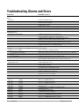
Troubleshooting . . . . . . . . . . . . . . . . . . . . . . . A.2
Modbus™ RTU . . . . . . . . . . . . . . . . . . . . . . . A.4
Calibrating the Series 97 . . . . . . . . . . . . . . . . A.11
Glossary . . . . . . . . . . . . . . . . . . . . . . . . . . . . A.14
Specifications . . . . . . . . . . . . . . . . . . . . . . . . A.18
Ordering Information . . . . . . . . . . . . . . . . . . . A.20
Index . . . . . . . . . . . . . . . . . . . . . . . . . . . . . . . A.21
Prompt Index . . . . . . . . . . . . . . . . . . . . . . . . . A.23
Declaration of Conformity. . . . . . . . . . . . . . . . A.24
Parameter setup order . . . . . . . . . . . . . . . . . . A.25
Fold out Software Map. . . . . . . . . . . . . A.25 - A.26
Warranty and Returns . . . . . . . . . . . . back cover
Figures and Tables
Inputs and outputs . . . . . . . . . . . . . . . . . . . . . . . . .1.1
Multiple panel cutout dimensions . . . . . . . . . . . . . .2.1
Installing the controller . . . . . . . . . . . . . . . . . . . . . .2.2a
Gap dimensions . . . . . . . . . . . . . . . . . . . . . . . . . . .2.2b
Removing the controller . . . . . . . . . . . . . . . . . . . . .2.3
Isolation blocks . . . . . . . . . . . . . . . . . . . . . . . . . . .3.2
Power wiring . . . . . . . . . . . . . . . . . . . . . . . . . . . . .3.3
Wiring example . . . . . . . . . . . . . . . . . . . . . . . . . . .3.4
Wiring notes . . . . . . . . . . . . . . . . . . . . . . . . . . . . .3.5
Input 1 Wiring
Thermocouple . . . . . . . . . . . . . . . . . . . . . . . .3.6a
RTD (2- or 3-Wire) 100Ω platinum . . . . . . . . .3.6b
Input 2 Wiring
Digital Event . . . . . . . . . . . . . . . . . . . . . . . . . .3.6c
Output 1 Limit Output Wiring
AC Outputs . . . . . . . . . . . . . . . . . . . . . . . . . .3.7a
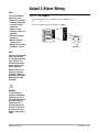
Output 2 Alarm Output Wiring
AC Outputs . . . . . . . . . . . . . . . . . . . . . . . . . .3.8a
Switched DC, Open Collector . . . . . . . . . . . . . . . . .3.8b
Output 3 Alarm Wiring
AC Outputs . . . . . . . . . . . . . . . . . . . . . . . . . .3.9
Output 4 wiring
AC Outputs . . . . . . . . . . . . . . . . . . . . . . . . . .3.10a
Communications and Retransmit . . . . . . . . . .3.10b
EIA-232 to EIA-435 Conversion . . . . . . . . . . . . . . .3.11a
EIA-232 to EIA-485 Converter . . . . . . . . . . . .3.11b
Keys and displays . . . . . . . . . . . . . . . . . . . . . . . . .4.2
Navigating the Series 97 . . . . . . . . . . . . . . . . . . . .4.3
Software Map . . . . . . . . . . . . . . . . . . . . . . . . . . . .4.4
Calibration offset . . . . . . . . . . . . . . . . . . . . . . . . . .5.3
Filtered and unfiltered input signals . . . . . . . . . . . .5.4
Sensor ranges . . . . . . . . . . . . . . . . . . . . . . . . . . . .5.5
Event inputs . . . . . . . . . . . . . . . . . . . . . . . . . . . . . .5.6
Retransmitting a remote set point . . . . . . . . . . . . . .5.7
Alarm settings . . . . . . . . . . . . . . . . . . . . . . . . . . . .5.8
Alarm latching . . . . . . . . . . . . . . . . . . . . . . . . . . . .5.9
Alarm silencing . . . . . . . . . . . . . . . . . . . . . . . . . . .5.10
Parameter setup order . . . . . . . . . . . . . . . . . . . . . .6.2
. . . . . . . . . . . . . . . . . . . . . . . . . . . . .inside back cover
TOTAL
About Watlow Winona
CUSTOMER
SATISFACTION
3 Year Warranty
Watlow Winona is a division of Watlow Electric Mfg. Co., St. Louis, Missouri, a
manufacturer of industrial electric heating products, since 1922. Watlow begins
with a full set of specifications and completes an industrial product that is
manufactured totally in-house, in the U.S.A.. Watlow products include electric
heaters, sensors, controllers and switching devices. The Winona operation has
been designing solid state electronic control devices since 1962, and has earned
the reputation as an excellent supplier to original equipment manufacturers.
These OEMs depend upon Watlow Winona to provide compatibly engineered
controls which they can incorporate into their products with confidence. Watlow
Winona resides in a 100,000 square foot marketing, engineering and
manufacturing facility in Winona, Minnesota.
ii ■ Table of Contents
Watlow Series 97
1
Chapter One
Overview
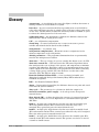
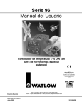
Introduction
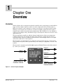
Watlow’s Series 97 is a microprocessor-based controller with a single input, second auxiliary
input and four outputs. Input 1 is used to measure temperature from a thermocouple or
RTD sensor. Input 2 can be utilized as a remote reset switch or a hardware lockout switch.
With up to four outputs, the controller is versatile in handling applications that require a
high/low limit, alarms, retransmit and communications. The controller is so user friendly it
can be set up to display safety and limit messages created by the end user to meet the exact
application need.
The Series 97 limit controller is added to thermal applications to limit over-temperature
conditions. The Series 97 controller provides safety assurance against instances where a
high temperature runaway condition could occur from a shorted input sensor or an output
device that could fail in a closed position.
The Series 97 is recommended for any application where thermal runaway could result in
large product scrap costs, affect operator safety, cause damage to equipment, or create a fire
hazard.
The Series 97 is manufactured by ISO 9001-registered Watlow Winona and reliably backed
by a three-year warranty.
LIMIT 97
Input 1
Process
Input 2
Remote Reset or
Hardware Lockout
1
2
3
4
Output 1
Limit Relay
Output 2
Alarm
Output 3
Alarm
RESET
Output 4
Alarm, Analog or
Communications
Figure 1.1 — Series 97 inputs and outputs.
Watlow Series 97
Over view ■ 1.1
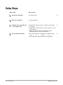
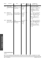
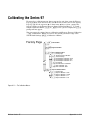
Setup Steps
What to do
How to do it
1
Install the controller.
See Chapter Two.
2
Wire the controller.
See Chapter Three.
3
Configure the controller for
your application.
Chapter Four explains the keys, displays and software
navigation.
Chapter Five explains features, such as alarms and control methods.
Chapter Six lists parameter descriptions, ranges,
Modbus numbers and other information.
4
Set up communications.
The controller must be equipped for communications,
(97_ _ - _ _ _ U - _ _ _ _ or 97_ _ - _ _ _ R - _ _ _ _).
See Chapter Five, Chapter Six and the Appendix.
1.2 ■ Over view
Watlow Series 97
2
Chapter Two
Installation
2.050"
1.77" to 1.79"
(44.96mm to 45.47mm)
LIMIT 97
1
2
3
4
Panel Cutout
2.050"
Panel
Thickness
0.06" to 0.38"
(1.5 to 9.7 mm)
1.77" to 1.79"
(44.96mm
to 45.47mm)
RESET
0.540"
(13.72mm)
Minimum
0.310"
(7.874mm)
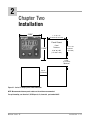
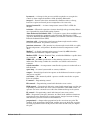
Figure 2.1 - Series 97 multiple panel cutout dimensions.
NOTE: Measurements between panel cutouts are the minimum recommended.
For rapid mounting, use Greenlee 1/16 DIN punch, die, draw stud, part number 60287.
Watlow Series 97
Installation ■ 2.1
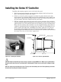
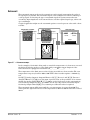
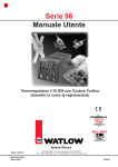
Installing the Series 97 Controller
Installing and mounting requires access to the back of the panel.
1. Make the panel cutout using the tear-out mounting template found on the previous
page, or the dimensions found in this chapter.
2. Check to see that the gasket is properly seated into the gasket channel on the front
bezel and that it is not twisted. Make sure that the rounded surface of the gasket is the
surface that is exposed from the gasket channel, as this is the surface that will mate to
the panel surface. Insert the controller into the panel cutout.
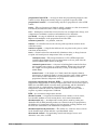
3. With the controller inserted into the panel cutout, take the retention collar and slide it
over the controller, making certain that the two locating holes in the retention collar are
visible from the rear of the controller, with one hole pointing up and one pointing down.
Then, take the mounting collar and slide it over the controller, making certain that one
cantilever is pointing up and one is pointing down also. With one hand holding the controller and the other hand using a #2 Phillips screw driver, tighten the two screws in
the mounting collar until the gap between the bezel and panel surface is .025” maximum. See figure below. Make sure that you cannot move the controller back and forth in
the cutout. If you can, you do not have a proper seal.
.025" Maximum gap
Retention Collar
Mounting Collar
Front Bezel
.325"
(8.6 mm)
Figure 2.2a - Installing the controller.
Customer's Front Panel
3.875"
(98.4 mm)
Figure 2.2b - Series 97 gap dimensions.
ç
CAUTION: Follow the installation procedure exactly to guarantee a proper NEMA 4X seal. Make sure the gasket between
the panel and the rim of the case is not twisted and is seated properly. Failure to do so could result in damage to equipment.
NOTE: Be careful not to over-tighten the screws. This may cause the mounting cover to fail. Over-tightening occurs when
the front bezel is touching the customer’s front panel.
2.2 ■ Installation
Watlow Series 97
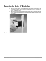
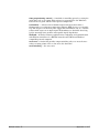
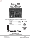
Removing the Series 97 Controller
1
Hold the controller with one hand while using the other hand to loosen the screws with
a #2 Phillips screwdriver until the end of the screw is flush or past the end of the cantilevers, see the figure below.
2. After the screws have been loosened, hold the controller with one hand while squeezing
the two screws together with the other hand. Then simply slide the mounting collar off
the controller.
Figure 2.3 - Removing the controller.
Watlow Series 97
Installation ■ 2.3
Notes
2.4 ■ Installation
Watlow Series 97
3
Chapter Three
Wiring
Power Wiring . . . . . . . . . . . . . . . . . . . . . .3.3
Sensor Installation Guidelines . . . . . . . . .3.3
Wiring Example . . . . . . . . . . . . . . . . . . . .3.4
Wiring Notes . . . . . . . . . . . . . . . . . . . . . .3.5
Input 1 . . . . . . . . . . . . . . . . . . . . . . . . . . .3.6
Input 2 . . . . . . . . . . . . . . . . . . . . . . . . . . .3.6
Output 1 Limit Output Wiring . . . . . . . . . .3.7
Output 2 Alarm Output Wiring . . . . . . . . .3.8
Output 3 Alarm Wiring . . . . . . . . . . . . . . .3.9
Output 4 . . . . . . . . . . . . . . . . . . . . . . . . .3.10
EIA Conversions . . . . . . . . . . . . . . . . . . .3.11
Watlow Series 97
Wiring ■ 3.1
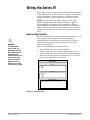
Wiring the Series 97
Wiring options depend on the model number. Check the terminal
designation stickers on either side of the controller and compare
your model number to those shown here and with the model
number breakdown on the inside back cover of this manual.
NOTE: Using the Diagnostics Menu (Factory Page) check
Output 1 Hardware through Output 4 Hardware, [Oty1]
through [Oty4]. See Chapter Six for information about the
menu and range of settings for each output. These outputs may
differ from those listed for the model number on the controller
and described in this manual, indicating a customized hardware
setup.
Input-to-output Isolation
∫
WARNING:
To avoid potential
electric shock, use
National Electric Code
(NEC) safety practices
when wiring and
connecting this unit to a
power source and to
electrical sensors or
peripheral devices.
Failure to do so could
result in injury or death.
The Series 97 uses optical and transformer isolation between the
analog inputs and the controller outputs, including the
communications interface. This isolation provides a barrier to
prevent ground loops when using grounded sensors and/or
peripheral equipment.
Here is a breakdown of the isolation barriers:
•
Analog inputs 1 and 2 are grouped together.
•
Outputs 1 through 4 are grouped together. This does not
apply to Output 4 when it is configured for communications.
•
If Output 4 is configured for communications, it is isolated
from the the other inputs and outputs.
Isolation Blocks
There are no electrical connections between these blocks.
INPUT
Input 1
Input 2
OUTPUT
Output 1
Output 2
Output 3
Output 4 (unless Output 4 is used for communications)
COMMUNICATIONS
Output 4 (if Output 4 is used for communications)
Figure 3.2 — Isolation blocks.
3.2 ■ Wiring
Watlow Series 97
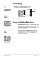
Power Wiring
ç
CAUTION:
If high voltage is applied
to a low-voltage unit,
irreversible damage will
occur.
100 to 240VÅ (ac), nominal (85 to 264 actual) 97 A _ - _ _ _ _ - _ _ _ _
24 to 28V‡ (ac/dc), nominal (21 to 30 actual) 97 B _ - _ _ _ _ - _ _ _ _
8
13
14
15
1
8
2
9
3
10
9
-
L2
+
L1
Fuse
11
4
16
17
18
12
5
6
ç∫
WARNING:
To avoid damage to
property and equipment,
and/or injury of loss of
life, use National Electric
Code (NEC) standard
wiring practices to install
and operate the Series
97. Failure to do so could
result in such damage,
and/or injury or death.
ç
CAUTION:
Maintain isolation
between input 1 and
input 2 to prevent a
ground loop. A ground
loop may cause incorrect
readings, dashes across
the upper display or the
display of error codes.
Failure to follow this
guideline could result in
damage to equipment.
Watlow Series 97
7
19
20
21
Figure 3.3 - Power wiring.
Sensor Installation Guidelines
Thermocouple inputs: Extension wire for thermocouples must
be of the same alloy as the thermocouple to limit errors.
When using a voltage input for the digital event on Input 2, use
an ungrounded thermocouple on Input 1. If a grounded
thermocouple is required, the signal to input 2 must be isolated
to prevent possible ground loops.
RTD input: Each 1Ω of lead wire resistance can cause a +2°F
error when using a two-wire RTD. A three-wire RTD sensor
overcomes this problem. All three wires must have the same
electrical resistance (i.e., same gauge, same length, multistranded or solid, same metal).
Wiring ■ 3.3
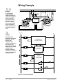
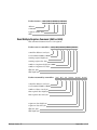
Wiring Example
∫ç
WARNING:
L1
120VÅ (ac)
L2
high
temperature
light
To avoid potential
electric shock and
damage to property and
equipment, use National
Electric Code (NEC)
safety practices when
wiring and connecting
this unit to a power
source and to electrical
sensors or peripheral
devices. Failure to do so
could result in injury or
death.
ç
fuse
high limit
mechanical
contactor
coil
16
14
15 (+)
13 (-)
13
14
15
9
2
9
3
10
3
4
16
17
3
optional
normally open
momentary switch
15
14
15
8
2
9
3
10
4
11
16
17
9
17
18
12
5
6
18
7 (+)
12
5
13
1
6 (-)
Heater
11
4
1
DIN-a-mite
DA10-24C0-0000
5
8
8
2
6
(+)
1
6 (-)
1
(-)
19
7
20
21
6
7 (+)
7
19
20
97A1-DDAA-00RR
Limit Controller
21
96AO-CAAA-OORR
rear view
process sensor
limit sensor
120VÅ (ac)
L1
L2
WARNING:
Install high or low
temperature limit control
protection in systems
where an over
temperature fault
condition could present a
fire hazard or other
hazard. Failure to install
temperature limit control
protection where a
potential hazard exists
could result in damage to
equipment, property and
injury to personnel.
1
9
1
8
3
2
4 (+)
2
5
3
(-)
Series 96
96A0 - CAAA - 00RR
Temperature Controller
7
6
15
4
1 CR-1
1
1
9
8
13
6 (+)
7 (-)
5
6
2
2
10
DIN-a-mite
DA10-24C0-0000
5
Heater
11
6
7
1
9
13
8
14
15
1
7
9
(+)
16
10
(-)
17
11
12
4
3
12
8
2
Series 97
97A1-DDAA-00RR
3
Limit Controller
6
15
18
14
1
1CR
2
19
13
16
17
1
20
21
R
2
high-temperature light
Figure 3.4 - System wiring example.
3.4 ■ Wiring
Watlow Series 97
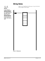
Wiring Notes
∫ç
Sketch in your application on this page or a copy of it. See the
wiring example in this chapter.
WARNING:
To avoid damage to
property and equipment,
and/or injury of loss of
life, use National Electric
Code (NEC) standard
wiring practices to
install and operate the
Series 97. Failure to do
so could result in such
damage, and/or injury or
death.
L1
L2
9
power
8
Figure 3.5 - Wiring notes.
Watlow Series 97
Wiring ■ 3.5
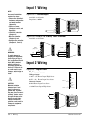
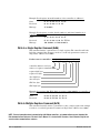
Input 1 Wiring
NOTE:
Successful installation
requires five steps:
• Choose the controller’s
hardware configuration
and model number
(Appendix);
Figure 3.6a – Thermocouple
Available on all units
Impedance: 20MΩ
13
14
15
1
8
2
9
3
10
11
4
• Choose a sensor
(Chapters 3 and 6, and
Appendix);
• Install the controller
(Chapter 2);
• Wire the controller
(Chapter 3) and
16
17
18
12
5
6
-6
+7
19
7
20
21
Figure 3.6b – RTD (2- or 3-Wire) 100Ω Platinum
Available on all units
• Configure the controller
(Chapters 4, 5 and 6).
1
1
ç
WARNING:
To avoid damage to
property and equipment,
and/or injury of loss of
life, use National Electric
Code (NEC) standard
wiring practices to
install and operate the
Series 97. Failure to do
so could result in such
damage, and/or injury or
death.
1
2
2-wire
jumper 5 to 6
2
3-wire
3
3
4
5
S3
S1
6
4
5
6
S2
5
S3
6
S1
7
7
7
5
6
7
Input 2 Wiring
Figure 3.6c – Digital Event
97 _ 1 - _ _ _ _ - _ _ _ _
+5V
Voltage input
3-36VÎ (dc) Event Input High State
ç
CAUTION:
3.6 ■ Wiring
2.67kΩ
EVENT
Contact closure
+
3
20kΩ
0-2kΩ Event Input Low State
100Ω
> 23kΩ Event Input High State
EVENT
1
-
- 1
13
14
15
8
1
+
Maintain isolation
between input 1 and
input 2 to prevent a
ground loop. A ground
loop may cause incorrect
readings, dashes across
the upper display or the
display of error codes.
Failure to follow this
guideline could result in
damage to equipment
and product.
0-2VÎ (dc) Event Input Low State
3
2
9
3
10
11
4
16
17
18
12
5
6
7
19
20
21
Watlow Series 97
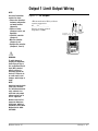
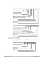
Output 1 Limit Output Wiring
NOTE:
Successful installation
requires five steps:
• Choose the controller’s
hardware configuration
and model number
(Appendix);
• Choose a sensor
(Chapters 3 and 6, and
Appendix);
• Install the controller
(Chapter 2);
• Wire the controller
(Chapter 3) and
• Configure the controller
(Chapters 4, 5 and 6).
Figure 3.7a – AC Outputs
•Electromechanical Relay without
contact suppression
97 _ _ - D _ _ _ - _ _ _ _
L1 L2
External
Load
Form C, 2 amps, off-state
impedance: 31MΩ
customer-supplied
N.C. COM. N.O. Quencharc
(13 used for
D outputs only) 13 14 15
13
14
15
8
1
2
9
3
10
11
4
16
17
18
12
5
6
ç
7
19
20
21
WARNING:
To avoid damage to
property and equipment,
and/or injury of loss of
life, use National Electric
Code (NEC) standard
wiring practices to
install and operate the
Series 97. Failure to do
so could result in such
damage, and/or injury or
death.
NOTE:
Switching inductive loads
(relay coils, solenoids,
etc.) with the mechanical
relay, switched dc or
solid-state relay output
options requires use of
an R.C. suppressor.
Watlow carries the R.C.
suppressor Quencharc
brand name, which is a
trademark of ITW Pakron.
Watlow Part No. 08040147-0000.
Watlow Series 97
Wiring ■ 3.7
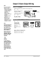
Output 2 Alarm Output Wiring
NOTE:
Successful installation
requires five steps:
• Choose the controller’s
hardware configuration
and model number
(Appendix);
• Choose a sensor
(Chapters 3 and 6, and
Appendix);
• Install the controller
(Chapter 2);
Figure 3.8a – AC Outputs
•Electromechanical relay without contact suppression
97 _ _ - _ D _ _ _ - _ _ _ _
13
Form C, 2 amps, off-state
impedance: 31MΩ
14
15
8
1
•Solid-state relay without
contact suppression
2
9
16
3
10
N.O. COM. N.C.
18
(18 used for
D outputs only)
11
4
16
17
18
12
5
External
Load
6
97 _ _ - _ K _ _ - _ _ _ _
17
19
7
20
0.5 amps, off-state
impedance: 31MΩ
21
customer-supplied
Quencharc
L1
L2
• Wire the controller
(Chapter 3) and
• Configure the controller
(Chapters 4, 5 and 6).
Figure 3.8b – Switched DC, Open Collector
97 _ _ - _ C _ _ - _ _ _ _
13
14
15
NOTE:
2
9
3
10
Maximum voltage:
28VÎ (dc)
Watlow carries the R.C.
suppressor Quencharc
brand name, which is a
trademark of ITW Pakron.
Watlow Part No. 08040147-0000.
Maximum voltage: 42VÎ (dc)
Maximum current:
30mA
11
4
Switching inductive loads
(relay coils, solenoids,
etc.) with the mechanical
relay, switched dc or
solid-state relay output
options requires use of
an R.C. suppressor.
22 to 28VÎ (dc)
+VÎ (dc)
8
1
Switched DC
configuration:
16
17
18
16
+ 16
17 18 COM.
5
Internal Circuitry
6
7
18
17
12
19
20
21
Switched DC
External
Load
Open collector configuration:
Maximum current: 200 mA
ç
WARNING:
To avoid damage to
property and equipment,
and/or injury of loss of
life, use National Electric
Code (NEC) standard
wiring practices to
install and operate the
Series 97. Failure to do
so could result in such
damage, and/or injury or
death.
3.8 ■ Wiring
Watlow Series 97
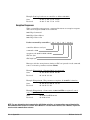
Output 3 Alarm Wiring
NOTE:
Successful installation
requires five steps:
• Choose the controller’s
hardware configuration
and model number
(Appendix);
• Choose a sensor
(Chapters 3 and 6, and
Appendix);
Figure 3.9 – AC Outputs
Electromechanical Relay without Contact Suppression
97 _ _ - _ _ D_ - _ _ _ _
Form C, 2 amps, off-state impedance: 31MΩ
13
15
8
2
9
3
10
• Install the controller
(Chapter 2);
4
• Wire the controller
(Chapter 3) and
7
• Configure the controller
(Chapters 4, 5 and 6).
14
1
11
16
17
18
12
5
6
19
20
10
N.C.
11
COM.
12
N.O.
L1
External
Load
L2
21
customer-supplied
Quencharc
NOTE:
Switching inductive loads
(relay coils, solenoids,
etc.) with the mechanical
relay, switched dc or
solid-state relay output
options requires use of
an R.C. suppressor.
Watlow carries the R.C.
suppressor Quencharc
brand name, which is a
trademark of ITW Pakron.
Watlow Part No. 08040147-0000.
ç
WARNING:
To avoid damage to
property and equipment,
and/or injury of loss of
life, use National Electric
Code (NEC) standard
wiring practices to
install and operate the
Series 97. Failure to do
so could result in such
damage, and/or injury or
death.
Watlow Series 97
Wiring ■ 3.9
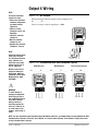
Output 4 Wiring
NOTE:
Successful installation
requires five steps:
• Choose the controller’s
hardware configuration
and model number
(Appendix);
Figure 3.10a – AC Outputs
Electromechanical Relay without Contact Suppression
97 _ _ - _ _ _ D - _ _ _ _
Form C, 2 amps, off-state impedance: 31MΩ
13
• Choose a sensor
(Chapters 3 and 6, and
Appendix);
1
• Install the controller
(Chapter 2);
5
14
15
8
2
9
3
10
11
4
16
17
18
12
6
19
7
20
21
• Wire the controller
(Chapter 3) and
• Configure the controller
(Chapters 4, 5 and 6).
19
NOTE:
Switching inductive loads
(relay coils, solenoids,
etc.) with the mechanical
relay, switched dc or
solid-state relay output
options requires use of
an R.C. suppressor.
Watlow carries the R.C.
suppressor Quencharc
brand name, which is a
trademark of ITW Pakron.
Watlow Part No. 08040147-0000.
External
Load
customer-supplied
Quencharc
L2
L1
Figure 3.10b – Communications and Retransmit Option
EIA/TIA-232
EIA/TIA-485
Retransmit Option
97 _ _ - _ _ _ R - _ _ _ _
97 _ _ - _ _ _ U - _ _ _ _
97_ _ - _ _ _ M - _ _ _ _
13
14
15
13
14
13
15
8
9
10
3
10
11
4
12
5
1
8
2
9
2
9
3
10
3
4
11
4
12
5
17
18
6
16
17
18
19
20
21
11
16
17
18
12
6
6
7
15
2
8
16
14
1
1
5
ç
20 21
N.O. COM. N.C.
19
7
20
21
19
7
20
21
WARNING:
To avoid damage to
property and equipment,
and/or injury of loss of
life, use National Electric
Code (NEC) standard
wiring practices to
install and operate the
Series 97. Failure to do
so could result in such
damage, and/or injury or
death.
19
20 21
19
20 21
T out
COM. R in
T-/R-
COM. T+/R+
19
20
21
V out
COM.
I out
NOTE: For more information about communicating with Watlow controllers, go to www.watlow.com and download the Data
Communications Reference: Electronic User’s Manual. It is located under Literature, User’s Manuals, English and search
on data communications reference.
3.10 ■ Wiring
Watlow Series 97
NOTE:
Figure 3.11a — EIA-232 to EIA-485 Conversion
TD (A)
TD (B)
RD (A)
RD (B)
EIA-485
485OIC
EIA-232
Successful installation
requires five steps:
• Choose the controller’s
hardware configuration
and model number
(Appendix);
• Choose a sensor
(Chapters 3 and 6, and
Appendix);
• Install the controller
(Chapter 2);
• Wire the controller
(Chapter 3) and
• Configure the controller
(Chapters 4, 5 and 6).
T-/RT+/R+
COM.
+12VÎ(dc)
GND
+12VÎ(dc)
GND (232 power)
EIA-485
+
Power Supply
–
AD-1210
19
21
20
120V~(ac)
B&B Converter (B&B Electronics Manufacturing Company, (815) 433-5100).
NOTE:
The CMC converter
requires an external
power supply when used
with a laptop computer.
NOTE:
If the system does not
work properly, it may need
termination resistors at
each end of the network. A
typical installation would
require a 120-ohm resistor
across the transmit/receive
terminals (19 and 21) of
the last controller in the
network and the converter
box or serial card. Pull-up
and pull-down resistors
may be needed to maintain the correct voltage
during the idle state.
Watlow Series 97
EIA-485
G
B
A
B
A
DI/O DI/O
To avoid damage to
property and equipment,
and/or injury of loss of
life, use National Electric
Code (NEC) standard
wiring practices to install
and operate the Series 97.
Failure to do so could
result in such damage,
and/or injury or death.
ADA485L
WARNING:
G
9VÎ
EIA-232
ç
120VÅ (ac)
9VÎ (dc) (see note)
COM.
T+/R+
T-/R-
20
21
19
0219-0217-0000
7 ft. comms cable
CMC Converter (CMC Connecticut Micro-Computer, Inc., 800-426-2872).
Figure 3.11b — Termination for EIA-232 to EIA-485 Converter
+5V
Converter box
termination
with pull-up
and pull-down
resistors.
B
T+/R+
A
T-/R-
GND
Com
1KΩ
120Ω
1KΩ
Wiring ■ 3.11
Notes
3.12 ■ Wiring
Watlow Series 97
4
Chapter Four
Navigation and Software
Keys and Displays . . . . . . . . . . . . . . . . . .4.2
Navigation . . . . . . . . . . . . . . . . . . . . . . . .4.3
Software Map . . . . . . . . . . . . . . . . . . . . .4.4
Task Charts . . . . . . . . . . . . . . . . . . . . . . .4.6
Watlow Series 97
Navigation ■ 4.1
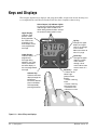
Keys and Displays
This chapter explains keys, displays and navigation skills, and presents charts showing how
to accomplish basic and advanced tasks. You’ll also find a complete software map.
Upper Display:
Indicates actual
process values
during operation,
the value for the
parameter in the
lower display, or the
user programmed
message.
Active Output (1-4) Indicator Lights:
Lit when the corresponding output trips.
Indicator light next to number 4 will
flicker during communications activity if
the communications option is used.
Lower Display:
Indicates factory
programmed
message during
operation, the value
for the parameter in
the lower display, or
the user programmed
message.
Advance Key:
Advances the lower
display through the
parameters.
To reverse direction,
press and hold ‰
while repeatedly
pressing the ¿ key.
LIMIT 97
1
2
3
4
RESET
Up Key:
Changes the upper
display to a higher
value, or up through
a list of values.
Moves from menu to
menu in a page.
Down Key:
Changes the upper
display to a lower
value, or down
through a list of
values. Moves from
menu to menu in a
page.
Reset Key:
• Returns to the
Home Page
(process/actual
display).
• Resets a latching
alarm.
• Resets a latching
input sensor error.
• Resets the limit.
• Silences an alarm.
Figure 4.2 — Series 97 keys and displays.
4.2 ■ Navigation
Watlow Series 97
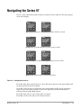
Navigating the Series 97
Choose a page (Operations, Setup or Factory) and press its key sequence. The page appears
in the lower display.
LIMIT 97
1
2
3
4
LIMIT 97
1
2
3
RESET
4
RESET
• Operations Page: press ¿ and ¯ keys together for three seconds.
LIMIT 97
LIMIT 97
1
2
3
1
4
2
3
4
RESET
RESET
• Setup Page: press ¿ and ¯ keys together for six seconds.
LIMIT 97
1
2
3
1
4
2
3
4
RESET
RESET
• Factory Page: press ‰ and Reset keys together for six seconds.
LIMIT 97
1
2
3
4
RESET
%
LIMIT 97
1
2
3
4
RESET
• Home Page: From anywhere, press the Reset Key.
Figure 4.3 — Navigating the Series 97.
Press ¯ or ¿ to find a specific menu in a page. The menu appears in the upper display and
the page remains in the lower display.
Press ‰ to enter the list of paramenters in the menu displayed. The menu’s parameters
appear in the lower display and the values in the upper. To go backward through the
parameter list press ‰ and ¿ together.
Press ¯ or ¿ to select a value, either alpha or numeric.
Press ‰ to set the value and go to the next parameter.
Watlow Series 97
Navigation ■ 4.3
Navigation
Home Page
‰ and RESET
for 6 seconds
¿ and ¯
for 3 seconds
Operations Page
¿ and ¯
for 3 seconds
Setup Page
[``97] Process Value
[Safe] Limit Status
[LIM] Limit Menu
[OPEr] Operations Page
[InP1] Input 1 Menu
[`SEt] Setup Page
[`LOC] Custom Menu
[FctY] Factory Page
¿ to cycle through menus
‰ to select a parameter in a menu
¿ to select a value
‰ to enter a value and go to the next parameter
RESET anytime to return to the Home Page
Factory Page
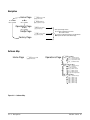
Software Map
Home Page
[``97]
Process Value
[safe] Limit Status
Operations Page
[LIM]
[OPEr]
¿
¯
‰
Limit Menu
[OPEr] Operations Page
[L`Lo] Low Limit Set Point
[L`hi] High Limit Set Point
[CAL1] Calibration Offset
[Mon] Monitor Menu
¯ [OPEr]
‰
¿
[OPEr] Operations Page
[Pr1`] Process 1
[L`St] Limit Status
[AL`2] Alarm 2 Status
[AL`3] Alarm 3 Status
[AL`4] Alarm 4 Status
[E`St] Event Input Status
[ALM] Alarm Menu
[OPEr]
‰
[OPEr] Operations Page
[A2Lo] Alarm 2 Low
[A2hi] Alarm 2 High
[A3Lo] Alarm 3 Low
[A3hi] Alarm 3 High
[A4Lo] Alarm 4 Low
[A4hi] Alarm 4 High
Figure 4.4 — Software Map.
4.4 ■ Navigation
Watlow Series 97
Setup Page
[InP1]
[`SEt]
¿
¯
‰
[InP2]
[`SEt]
¿
¯
‰
[Out1]
[`SEt]
¿
¯
‰
[Out2]
[`SEt]
‰
¿
¯
[Out3]
[`SEt]
‰
¿
¯
[Out4]
[`SEt]
‰
¿
¯
Input 2 Menu
[`SEt] Setup Page
[In`2] Input 2
[E`Fn] Event Function
[E`cn] Event Condition
Output 1 Menu
[`SEt] Setup Page
[LSid] Set Limit Active Sides
[LhYS] Limit Hysteresis
Output 2 Menu
[`SEt] Setup Page
[Ot`2] Output 2
[hys2] Alarm Hysteresis 2
[LAt2] Latching 2
[SiL2] Silencing 2
[Sid2] Alarm Active Sides 2
[Lgc2] Alarm Logic 2
[Anu2] Alarm Annunciation 2
Output 3 Menu
[`SEt]
[Ot`3]
[hys3]
[LAt3]
[SiL3]
[Sid3]
[Lgc3]
[Anu3]
Setup Page
Output 3
Alarm Hysteresis 3
Latching 3
Silencing 3
Alarm Active Sides 3
Alarm Logic 3
Alarm Annunciation 3
Display Menu
[Udsp] Upper Display
[UP`L] Upper Display
User Limit Message
[Ldsp] Lower Display
[Lo`S] Lower Display
User Safe Message
[Lo`L] Lower Display
User Limit Message
[GLbL]
[`SEt]
‰
[`LOC]
Lockout Menu
[FctY]
¿
¯
‰
[Fcty]
[OPEr]
[`SEt]
[`CAL]
Factory Page
Operations Page Mode
Setup Page Lock
Calibration Menu Lock
[dIAg]
Diagnostics Menu
[FctY]
[Fcty]
[MdL]
[dAtE]
[`Sn1]
[`Sn2]
[Soft]
[`rEu]
[Ity2]
[Oty1]
[Oty2]
[Oty3]
[Oty4]
[tout]
[dISP]
[hrES]
[AMb]
[Acnt]
[cnt1]
[cnt2]
[tSht]
‰
Factory Page
Model Number
Date of Manufacture
Serial Number 1
Serial Number 2
Software ID Number
Software Revision
Input 2 Hardware Enabled
Output 1 Hardware
Output 2 Hardware
Output 3 Hardware
Output 4 Hardware
Test Output
Test Displays
High Resolution
Ambient Temperature
Ambient A-D Counts
Channel 1 A-D Counts
Channel 2 A-D Counts
Communication Test /
Troubleshooting
[Line] Line Frequency
Note: The Factory Page also includes calibration
parameters that are not necessary for everyday use of
the controller. Calibration parameters and procedures
are explained in the Appendix.
Setup Page
Output 4
Alarm Hysteresis 4
Latching 4
Silencing 4
Alarm Active Sides 4
Alarm Logic 4
Alarm Annunciation 4
Analog Output 4
Process 4 Type
Analog Output High
Analog Output Low
Analog Output Offset
Baud Rate
Address
[`SEt]
¿
¯
Factory Page
Output 4 Menu
[`SEt]
[Ot`4]
[hys4]
[LAt4]
[SiL4]
[Sid4]
[Lgc4]
[Anu4]
[Aout]
[Prc4]
[A`hi]
[A`Lo]
[ACAL]
[BaUd]
[Addr]
[Disp]
‰
Watlow Series 97
Input 1 Menu
[`SEt] Setup Page
[SEn1] Sensor Type 1
[In`1] Input 1
[rL`1] Range Low 1
[rh`1] Range High 1
[dEC1] Decimal 1
[Ftr1] Input Software Filter 1
Global Menu
[`SEt] Setup Page
[`C-F] C or F
[`Err] Input Error Latching
Navigation ■ 4.5
Tip: Use the software map on the inside back
cover for easy reference.
Basic navigation for new users
Use this example task to learn how to use the keys and displays. Navigation skills are
essential for setting up the controller. For more information about the control features available in the Series 97, see Chapter Five. For a table of all parameters and values, see
Chapter Six.
Configure the controller
To configure the controller to suit your application, go to the Setup Page, enter the menus
and set the parameters for the system, its inputs and outputs.
Do this
Press these keys
You’ll see*
1
Go to the Setup
Page from the
Home Page.
¿Up-arrow and
¯Down-arrow
keys for 6 seconds.
After three seconds the Operations
Page appears in the lower display; after six seconds the Setup
Page appears in the lower display. A menu is in the upper display.
[InP1]
2
Select a menu to
enter.
¿Up-arrow key.
The Setup Page remains in the
lower display while menu names
appear in the upper display.
[Inp2]
3
Go to a parameter.
‰Advance key.
The menu’s parameters appear in
the lower display and the values
appear in the upper display.
[Off`]
[`SEt]
[`SEt]
[In`2]
(Note: When you enter a menu, the
display changes. Instead of the
Setup Page and menu, you see
parameter and value.)
4
Choose a value.
5
Set a value and
go on to the
next parameter.
Summary
¿Up-arrow key,
until you reach the
desired value.
Values appear in the upper display
when the parameter is in the
lower display.
[E`In]
‰Advance key
(when the chosen
value is displayed).
You will see the chosen value in the
upper display. After pressing the
Advance key, the next parameter
appears in the lower display, with
one of its values in the upper display. Values auto-enter after five
seconds.
[none]
[In`2]
[E`Fn]
To make a selection or choice:
Press ¿Up-arrow key or ¯Down-arrow key.
To move or change location in
a page or menu:
Press ‰Advance key or Reset Key.
*What you see depends on the options included in your controller.
4.6 ■ Navigation
Watlow Series 97
5
Chapter Five
Features
Limit . . . . . . . . . . . . . . . . . . . . . . . . . . . .5.2
Input
Calibration Offset . . . . . . . . . . . . . . . .5.3
Filter Time Constant . . . . . . . . . . . . .5.4
Sensor Selection . . . . . . . . . . . . . . . .5.5
Range Low and Range High . . . . . . .5.5
Event Input . . . . . . . . . . . . . . . . . . . .5.6
Retransmitting the process value . . . .5.7
Alarms
Alarm Set Points . . . . . . . . . . . . . . . .5.8
Alarm Hysteresis . . . . . . . . . . . . . . . .5.8
Process or Deviation Alarms . . . . . . .5.9
Alarm Latching . . . . . . . . . . . . . . . . .5.9
Alarm Silencing . . . . . . . . . . . . . . . . .5.10
Communications
Overview . . . . . . . . . . . . . . . . . . . . . .5.11
Watlow Series 97
Features ■ 5.1
Limit
The Series 97 limit controller is added to thermal applications to limit over- or under-temperature conditions. The Series 97 controller provides safety assurance against instances
where a high temperature runaway condition could occur from a shorted input sensor or an
output device that could fail in a closed position. A limit condition is latched and therefore
requires operator intervention to clear it. This is done by pressing the Reset key after the
limit condition has passed.
The Series 97 is recommended for any application where thermal runaway could result in
large product scrap costs, affect operator safety, cause damage to equipment or create a fire
hazard.
5.2 ■ Features
Watlow Series 97
Input
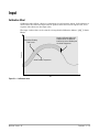
Calibration Offset
Calibration offset allows a device to compensate for an inaccurate sensor, lead resistance or
other factors that affect the input value. A positive offset increases the input value, and a
negative offset decreases the input value.
The input 1 offset value can be viewed or changed with Calibration Offset 1 [CAL1] (Limit
Menu).
Negative Calibration Offset will
compensate for the difference
between the Sensor Reading and
the Actual Temperature.
Temperature
Temperature Reading
from Sensor
Actual Process Temperature
Time
Figure 5.3 — Calibration offset.
Watlow Series 97
Features ■ 5.3
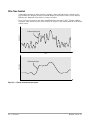
Filter Time Constant
A time filter smooths an input signal by applying a first-order filter time constant to the
signal. Either the displayed value or both the displayed and control values can be filtered.
Filtering the displayed value makes it easier to monitor.
View or change the input 1 time filter with Filter Time Constant 1 [Ftr1] (Input 1 Menu).
A positive value affects only the viewed values. A negative value affects both the viewed and
control values.
Temperature
Unfiltered Input Signal
Time
Temperature
Filtered Input Signal
Time
Figure 5.4 — Filtered and unfiltered input signals.
5.4 ■ Features
Watlow Series 97
Sensor Selection
You need to configure a controller to match the input device, which is normally a thermocouple or RTD. When you select an input device the controller automatically sets the input
linearization to match the sensor. It also sets high and low limits, which in turn limit the
range high and range low values.
Use Sensor Type 1 [SEn1] and Input 1 [In1`] (Input 1 Menu) to select the appropriate
sensor for input 1.
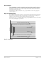
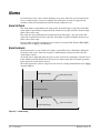
Range Low and Range High
The controller constrains the set point to a value between range high and range low. Range
high cannot be set higher than the sensor high limit or lower than range low. Range low
cannot be set lower than the sensor low limit or higher than range high.
Use Range Low 1 [rL1`] and Range High 1 [rh1`] (Input 1 Menu) to select or view values
for the corresponding input 1 parameters.
High Limit of selected Sensor Range
Range High Range (between High Limit of Sensor and Range Low)
Temperature
Range High
Range Low
Range Low Range (between Low Limit of Sensor and Range High)
Low Limit of selected Sensor Range
Figure 5.5 — Sensor ranges.
Watlow Series 97
Features ■ 5.5
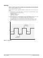
Event Input
With an event input an operator can perform certain operations on a system by opening or
closing a switch or applying a dc logic signal to the controller. This feature can add convenience, safety or security to a system.
Use Event Input Status [E`St] (Monitor Menu) to read the state of the event input parameter.
Use Event Function [E`Fn] (Input 2 Menu) to select how an event will affect the system.
[nonE] Events will not affect the system.
[Lrst] Clear Limit.
[`LOC] Lock out key board.
[`ALr] Clear an alarm.
Use Event Condition [E`cn] (Input 2 Menu) to select what condition will trigger an event.
[`Lo`] Low generates an event while the voltage is low (switch closed).
[`hi`] High generates an event while the voltage is high (switch open).
[riSE] Rise changes the event state when the voltage changes from low to high.
[FALL] Fall changes the event state when the voltage changes from high to low.
Voltage
High Event
(Switch open)
Rise Event
Fall Event
Low Event
(switch closed)
Time
Figure 5.6 — Event inputs.
5.6 ■ Features
Watlow Series 97
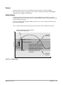
Retransmit
The retransmit output can be used to transmit an analog signal representing the value of
the input process variable. The retransmit signal can be configured as either a milliamp or
a voltage signal. In choosing the type of retransmit signal the operator must take into
account the input impedance of the external device and the required signal type, either voltage or milliamps.
A typical application might use the retransmit option to record a process value with a chart
recorder.
Temperature Controller
input 1
96
1
2
3
4
%
Heat-treat Oven
Limit Controller
LIMIT 97
output 1
1
2
3
4
output 1
input 1
input 2
limit
sensor
RESET
temperature
sensor
output 4
heater
Chart Recorder
Figure 5.7 — Retransmit example.
In the example a Series 96 is being used to control the temperature of a heat-treat oven and
the Series 97 is being used as a safety limit with a retransmit output. Output 4 of the
Series 97 must be equipped for retransmit (97_ _ - _ _ _ M - _ _ _ _).
The temperature of the limit process value is being recorded on a chart recorder. The oven
temperature range stays between 600 to 900°F. The chart recorder requires a 4-20mA signal.
Set [Aout] Analog Output 4 (Output 4 Menu) to [Proc] Process 1 and [Prc4] Process 4
(Output 4 Menu) to [4-20] to tag the input 1 process value as the parameter to be retransmitted. Set Analog Output High [A`hi] to 900 to set the high range for the retransmit signal. Set Analog Output Low [A`Lo] to 600 to set the low range for the retransmit signal.
Set Analog Output Offset [ACAL] to 0, assuming no calibration offset is required.
The retransmit output will be 4mA until the oven temperature is greater than 600°F, at
which point the signal will increase with temperature to 20mA at 900°F and will not exceed
20mA.
Watlow Series 97
Features ■ 5.7
Alarms
An alarm takes some action, usually notifying an operator, when the process temperature
leaves a defined range. A user can configure how and when an alarm is triggered and
whether it turns off automatically when the alarm condition is over.
Alarm Set Points
The alarm high set point defines the temperature that will trigger a high side alarm. The
alarm high set point must be higher than the alarm low set point and lower than the high
limit of the sensor range.
The alarm low set point defines the temperature that will trigger a low side alarm. The
alarm low set point must be lower than the alarm high set point and higher than the low
limit of the sensor range.
Process alarm set points for output 2 can be viewed or changed with Alarm 2 High [A2hi]
and Alarm 2 Low [A2Lo] (Alarm Menu).
Alarm Hysteresis
Alarm hysteresis is a zone inside each alarm set point. This zone is defined by adding the
hysteresis value to the alarm low set point or subtracting the hysteresis value from the
alarm high set point.
An alarm state is triggered when the process value reaches the alarm high or alarm low set
point. Alarm hysteresis defines how far the process must return into the normal operating
range before the alarm can be cleared.
The alarm hysteresis value for output 2 can be viewed or changed with Hysteresis 2 [hYS2]
(Output 2 Menu).
High Side Alarm Range
Alarm High Set Point
Temperature
Alarm Hysteresis
Normal Operating Range
Alarm Hysteresis
Alarm Low Set Point
Low Side Alarm Range
Time
Figure 5.8 — Alarm settings.
5.8 ■ Features
Watlow Series 97
Process
A process alarm uses one or two absolute set points to define an alarm condition.
The alarm process value of output 2 can be viewed or changed with Alarm 2 High [A2hi]
and Alarm 2 Low [A2Lo] (Alarm Menu).
Alarm Latching
A latched alarm will remain active after the alarm condition has passed. It can only be
deactivated by the user. An alarm that is not latched will deactivate automatically when the
alarm condition has passed.
Alarm 2 Latching [LAt2] (Output 2 Menu) allows you to view or change whether the output 2 alarm will latch.
Clear a latched alarm by pressing the Reset key after the alarm condition has passed.
The alarm state begins when the temperature
reaches the alarm high set point.
Alarm High
Set Point
Temperature
Alarm Hysteresis
Normal Operating Range
Process
Temperature
The alarm state continues until the
temperature drops to the alarm high
set point minus the hysteresis. A
latching alarm could be turned off by
the operator at this point. A nonlatching alarm would turn off
automatically.
Alarm Low
Set Point
Time
Figure 5.9 — Alarm latching.
Watlow Series 97
Features ■ 5.9
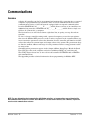
Alarm Silencing
Alarm silencing has two uses:
1. It is often used to allow a system to warm up after it has been started up. With alarm
silencing on, an alarm is not triggered when the process temperature is initially lower
than the alarm low set point. The process temperature has to enter the normal operating range beyond the hysteresis zone in order to activate the alarm function.
2. Alarm silencing also allows the operator to disable the alarm output while the controller
is in an alarm state. The process temperature has to enter the normal operating range
beyond the hysteresis zone in order to activate the alarm output function.
Alarm Silencing 2 [SiL2] (Output 2 Menu) allows you to view or change whether alarm
silencing is on. If Alarm Annunciation 2 [Anu2] (Output 2 Menu) is set to [`YES], the output 2 indicator light will remain on and an alarm message will appear in the display, even
though the alarm is silenced.
Alarm High
Set Point
Temperature
Hysteresis
Process
Temperature
Normal Operating Range
Alarm
enabled
here
Hysteresis
Startup,
Alarm
disabled
Alarm
triggered
here
Alarm Low
Set Point
Time
Figure 5.10 — Alarm silencing.
5.10 ■ Features
Watlow Series 97
Communications
Overview
A Series 97 controller can also be programmed and monitored by connecting it to a personal
computer or programmable logic controller (PLC) via serial communications. To use this
communications option, a Series 97 must be equipped with an output 4 communications
board for EIA/TIA-485 (97_ _ - _ _ _U - _ _ _ _), which allows as many as 32 controllers on a
4,000-foot-long network, or EIA/TIA-232 (97_ _ - _ _ _R - _ _ _ _), which allows a single controller to be connected to a computer.
The Series 97 uses an 8-N-1 data format (eight data bits, no parity, one stop bit and one
start bit).
To view or change controller settings with a personal computer, you need to run software
that uses the Modbus RTU protocol to read or write to registers in the controller. These registers contain the parameter values that determine how the controller will function and the
values that reflect the current input and output values of the system. The parameters chapter lists the modbus address and range for each parameter. Refer to setup parameter table
for setup order.
Communications parameters appear in the Output 4 Menu (Setup Page). Match the Baud
Rate [baud] to that of the computer and select an Address [Addr] for each Series 97.
The wiring chapter shows how to wire a Series 97 controller for EIA/TIA-485 or EIA/TIA232 communications.
The Appendix provides technical information about programming for Modbus RTU.
NOTE: For more information about communicating with Watlow controllers, go to www.watlow.com and download the
Data Communications Reference: Electronic User’s Manual. It is located under Literature, User’s Manuals, English and
search on data communications reference.
Watlow Series 97
Features ■ 5.11
Notes
5.12 ■ Features
Watlow Series 97
6
Chapter Six
Parameters
Parameter Setup Order . . . . . . . . . . . . . .6.2
Home Page . . . . . . . . . . . . . . . . . . . . . . .6.3
Operations Page . . . . . . . . . . . . . . . . . . .6.4
Monitor Menu . . . . . . . . . . . . . . . . . .6.4
Limit Menu . . . . . . . . . . . . . . . . . . . . .6.5
Alarm Menu . . . . . . . . . . . . . . . . . . . .6.5
Setup Page . . . . . . . . . . . . . . . . . . . . . . .6.7
Input 1 Menu . . . . . . . . . . . . . . . . . . .6.7
Input 2 Menu . . . . . . . . . . . . . . . . . . .6.9
Output 1 Menu . . . . . . . . . . . . . . . . . .6.9
Output 2 Menu . . . . . . . . . . . . . . . . . .6.9
Output 3 Menu . . . . . . . . . . . . . . . . . .6.11
Output 4 Menu . . . . . . . . . . . . . . . . . .6.12
Display Menu . . . . . . . . . . . . . . . . . . .6.14
Global Menu . . . . . . . . . . . . . . . . . . .6.16
Factory Page . . . . . . . . . . . . . . . . . . . . . .6.17
Lockout Menu . . . . . . . . . . . . . . . . . .6.17
Diagnostics Menu . . . . . . . . . . . . . . .6.17
Input Calibration Menu . . . . . . . . . . . .6.20
Output Calibration Menu . . . . . . . . . .6.21
NOTE: To see how all the pages, menus and parameters are grouped, refer to the gatefold back cover of this manual.
For more information about how parameter settings affect the controller’s operation, see Chapter Five, Features.
Watlow Series 97
Parameters ■ 6.1
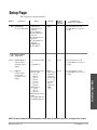
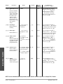
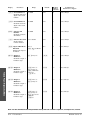
Table 6.2 — Set up
parameters in this
order.
Input 2 [In`2]
Decimal 1 [DeC1]
Range Low [rL`1]
Range High 1 [rh`1]
Input 1 [In`1]
Sensor Type [Sen1]
Output 2 [Out2]
Output 1 [Out1]
°C or °F [`C-F]
Changing this
Affects this
°C or °F [`C-F]
Output 1 [Out1]
Output 2 [Out2]
Output 3 [Out3]
Output 4 [Out4]
Sensor Type [Sen1]
Input 1 [In`1]
O
Range High 1 [rh`1]
C
D
D
C
Range Low [rL`1]
C
D
D
C
D
D
D
D
C
D
D
O
Decimal 1 [DeC1]
Calibration Offset 1 [Cal1]
C
Input Software Filter 1 [Ftr1]
Input 2 [In`2]
Key:
D = Changing will change
the default
C = Changing will convert
the
temperature scale
O = Other effect
Event Function [E`fn]
O
Event Condition [E`cn]
O
Analog Output 4 [Aout]
D
D
Analog Output High [A`hi]
C
D
D
Analog Output Low [A`lo]
C
D
D
C
C
Analog Output Offset [ACAL]
C
D
D
C
Alarm Hysteresis 2, 3, 4 [hys2] 3] 4]
C
D
D
C
Alarm 2, 3, 4 High [A2hi] 3] 4]
C
D
D
C
Alarm 2, 3, 4 Low [A2lo] 3] 4]
C
D
D
C
Alarm Latching 2, 3, 4 [Lat2] 3] 4]
Alarm Silencing 2, 3, 4 [Sil2] 3] 4]
Alarm Active Sides 2, 3, 4 [Sid2] 3] 4]
Alarm Logic 2, 3, 4 [Lgc2] 3] 4]
Parameter Setup Order
6.2 ■ Parameters
Watlow Series 97
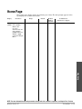
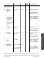
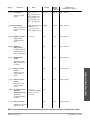
Home Page
The resting-state display shows the following set of data. The first prompt appears in the
top display, the second in the bottom.
Display
Parameter
[``97] Upper Display
Range
Default
Modbus
Address
read/write
Conditions for
Parameters to Appear
Active: Always
[safe] Lower Display
Home Page
Monitor the
processes
determined by the
Upper Display
[UdSP] and Lower
Display [LdSp]
parameters Display
Menu.
NOTE: For more information about how parameter seetings affect the controller’s operation, see Chapter Five, Features.
Watlow Series 97
Parameters ■ 6.3
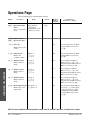
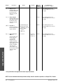
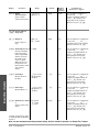
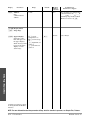
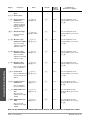
Operations Page
The operations page contains three menus:
Display
Parameter
[Oper] Operations Page
Select
Go to an operations
menu.
Range
[Mon] Monitor
[LIM] Limit
[Alm] Alarm (if any
alarms are active)
Default
Modbus
Address
read/write
Conditions for
Parameters to Appear
[LIM]
[mon] Monitor Menu
[Oper] Operations Page
100 r
Active if Operations Page Mode
(Lockout Menu) is not set to
[hide].
[SAFE] (0)
[``hi] (1)
[``Lo] (2)
319 r
Active if Operations Page Mode
(Lockout Menu) is not set to
[hide].
[nonE] (0)
[``Lo] (1)
[``hi] (2)
106 r
Active if Output 2 (Output 2
Menu) is set to [``AL] and
Operations Page Mode (Lockout
Menu) is not set to [hide].
[nonE] (0)
[``Lo] (1)
[``hi] (2)
110 r
Active if Output 3 (Output 3
Menu) is set to [``AL] and
Operations Page Mode (Lockout
Menu) is not set to [hide].
[nonE] (0)
[``Lo] (1)
[``hi] (2)
114 r
Active if Output 4 (Output 4
Menu) is set to [``AL] and
Operations Page Mode (Lockout
Menu) is not set to [hide].
201 r
Active if Input 2 (Input 2 Menu)
is set to [E`In] (event input),
[`EFn] is not set to [none]
and Operations Page Mode
(Lockout Menu) is not set to
[hide].
[`Pr1] Process 1
Monitor the process
1 value.
[L`St] Limit Status
Monitor the
condition of limit.
[AL`2] Alarm 2 Status
Monitor alarm 2
status.
[AL`3] Alarm 3 Status
Operations Page / Monitor Menu
Monitor alarm 3
status.
[AL`4] Alarm 4 Status
Monitor alarm 4
status.
[E`St] Event Input Status [FALS] false (0)
[truE] true (1)
Monitor the event
input status.
NOTE: For more information about how parameter settings affect the controller’s operation, see Chapter Five, Features.
6.4 ■ Parameters
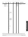
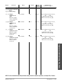
Watlow Series 97
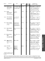
Display
Parameter
Range
Default
Modbus
Address
read/write
Conditions for
Parameters to Appear
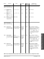
[LIM] Limit Menu
[Oper] Operations Page
[L`Lo] Low Limit Set
Point
[`rL1] to [L`hi] -1
[`rL1]
701 r/w
Active: Always
[L`Lo] +1 to [`rh1]
[`rh1]
702 r/w
Active: Always
0
605 r/w
Active: Always
321 r/w
Active if Output 2 (Output 2
Menu) is set to [``AL] (Alarm),
Alarm Active Sides 2 (Output 2
Menu) is not set to [hi``],
Output 2 is present (97 _ _-_ D
_ _-_ _ _ _ or 97 _ _-_ K_ _-_ _ _
_) and Operations Page Mode
(Lockout Menu) is not set to
[hide].
Process:
Process: high 322 r/w
Alarm 2 Low +1 to
limit of
high limit of selected
selected
sensor range
sensor
range
Active if Output 2 (Output 2
Menu) is set to [``AL] (Alarm),
Alarm Active Sides 2 (Output 2
Menu) is not set to [Lo``],
Output 2 is present (97 _ _-_ D
_ _-_ _ _ _ or 97 _ _-_ K_ _-_ _ _
_) and Operations Page Mode
(Lockout Menu) is not set to
[hide].
Process: low limit of
Process: low
selected sensor range
limit of
to Alarm 3 High -1
selected
sensor
range
Active if Output 3 (Output 3
Menu) is [``AL] (Alarm),
Alarm Sides 3 (Output 3 Menu)
is not [hi``], or Output 3 is
present (97 _ _-_ _ D _-_ _ _ _)
and Operations Page Mode
(Lockout Menu) is not set to
[hide].
Sets the low limit
point.
[L`hi] High Limit Set
Point
Sets the high limit
point.
[CAL1] Calibration Offset -1999 to 9999
Sets the input 1
calibration offset.
[Alm] Alarm Menu
[A2Lo] Alarm 2 Low
Sets the low alarm
set point for output
2.
[A2hi] Alarm 2 High
Sets the high alarm
set point for output
2.
[A3Lo] Alarm 3 Low
Sets the low alarm
set point for output
3.
Process: low limit of
Process: low
selected sensor range
limit of
to Alarm 2 High -1
selected
sensor
range
340 r/w
NOTE: For more information about how parameter settings affect the controller’s operation, see Chapter Five, Features.
Watlow Series 97
Parameters ■ 6.5
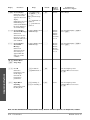
Operations Page / Alarm and Limit Menus
[Oper] Operations Page
Display
Parameter
[A3hi] Alarm 3 High
Sets the high alarm
set point for output
3.
[A4Lo] Alarm 4 Low
Sets the low alarm
set point for output
4.
[A4hi] Alarm 4 High
Sets the high alarm
set point for output
4.
Range
Default
Modbus
Address
read/write
Conditions for
Parameters to Appear
Process:
Process: high 341 r/w
Alarm 3 Low +1 to
limit of
high limit of selected
selected
sensor range
sensor
range
Active if Output 3 (Output 3
Menu) is [``AL] (Alarm),
Alarm Sides 3 (Output 3 Menu)
is set to [lo``], Output 3 is
present (97 _ _-_ _ D _-_ _ _ _)
and Operations Page Mode
(Lockout Menu) is not set to
[hide].
Process: low limit of
Process: low
selected sensor range
limit of
to Alarm 4 High -1
selected
sensor
range
none*
Active if Output 4 (Output Menu
4) is [``AL] (Alarm), Alarm
Sides 4 (Output Menu 4) is not
[hi``], Output 4 is a relay
(97 _ _-_ _ _ D-_ _ _ _) and
Operations Page Mode
(Lockout Menu) is not set to
[hide].
Process:
Process: high none*
Alarm 4 Low +1 to
limit of
high limit of selected
selected
sensor range
sensor
range
Active if Output 4 (Output Menu
4) is [``AL] (Alarm), Alarm
Sides 4 (Output Menu 4) is not
set to [lo``], Output 4 is a
relay (97 _ _-_ _ _ D-_ _ _ _)
and Operations Page Mode
(Lockout Menu) is not set to
[hide].
Operations Page / Alarm Menu
*Output 4 parameters cannot
be changed with the Modbus
interface.
NOTE: For more information about how parameter seetings affect the controller’s operation, see Chapter Five, Features.
6.6 ■ Parameters
Watlow Series 97
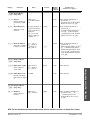
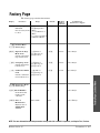
Setup Page
The setup page contains 8 menus.
Display
Parameter
Range
[`Set] Setup Page
[InP1] Input 1
Go to a setup menu. [Inp2] Input 2 (if
present)
[Out1] Output 1
[Out2] Output 2 (if
present)
[Out3] Output 3 (if
present)
[Out4] Output 4 (if
present)
[dISP] Display
[glbl] Global
Default
Modbus
Address
read/write
Conditions for
Parameters to Appear
Active if Setup Page Lock
(Lockout Menu) is not set to
[hide].
[InP1]
[Inp1] Input 1 Menu
[`set] Setup Page
Sets the input
hardware type of
input 1.
[In`1] Input 1
Sets the input
linearization
parameter of the
input 1.
600 r/w
Active if Setup Page Lock
(Lockout Menu) is not set to
[hide].
If Sensor Type is set to If Sensor
601 r/w
thermocouple
Type (Input
1 Menu) is
[```j] J (0)
changed to
[```H] K (1)
thermocoup
[```T] T (2)
[```e] E (3)
le: [```j],
if Sensor
[```n] N (4)
Type is
[```C] C (5)
changed to
[```d] D (6)
RTD:
[`Pt2] PT2 (7)
[```r] R (8)
[`din]
[```s] S (9)
[```b] B (10)
if Sensor Type is set to
RTD
[`din] RTD_DIN (11)
[`JIS] RTD_JIS (12)
Active if Setup Page Lock
(Lockout Menu) is not set to
[hide].
[``tc] Thermocouple
(0)
[`RTD] RTD (1)
[``tc]
Setup Page / Input 1 Menu
[Sen1] Sensor Type 1
NOTE: For more information about how parameter settings affect the controller’s operation, see Chapter Five, Features.
Watlow Series 97
Parameters ■ 6.7
Display
Parameter
[rL`1] Range Low 1
Range
Default
Modbus
Address
read/write
*
*
602 r/w
Active if Setup Page Lock
(Lockout Menu) is not set to
[hide].
*
*
603 r/w
Active if Setup Page Lock
(Lockout Menu) is not set to
[hide].
Sets the input range
low. This setting is
the lowest value
that the set point
can have.
[rh`1] Range High 1
Sets the input range
high. This setting is
the highest value
that the set point
can have.
[dEC1] Decimal 1
Sets the position of
the decimal point for
input readings.
[ftr1] Input Software
Filter 1
Sets the filter time
for the input, in
seconds. This
smooths out a
rapidly changing
input signal. Positive
values affect the
monitor readings
only. Negative
values affect both
the monitor readings
and the control
values.
Conditions for
Parameters to Appear
If Set Sensor Type is
RTD, thermocouple,
(excluding R, S, or B
thermocouple)
[```0] 0(0)
[``)0] 0.0(1)
0
606 r/w
Active if Setup Page Lock
(Lockout Menu) is not set to
[hide].
-60.0 to 60.0
0 (or 1.0 if
[dEC1] is
set to 0.0)
604 r/w
Active if Setup Page Lock
(Lockout Menu) is not set to
[hide].
Setup Page / Input 1 Menu
*See specifications in the appendix for sensor ranges and defaults.
NOTE: For more information about how parameter settings affect the controller’s operation, see Chapter Five, Features.
6.8 ■ Parameters
Watlow Series 97
Display
Parameter
Range
Default
Modbus
Address
read/write
Conditions for
Parameters to Appear
[Inp2] Input 2 Menu
[`set] Setup Page
[In`2] Input 2
Sets the input type
parameter of input
2.
[E`Fn] Event Function
Selects the event
function.
[`OFF] off: (0)
[E`In] Event Input:
(1)
0
611 r/w
Active if Input 2 hardware is
present (97 _1 _-_ _ _ _ -_ _ _ _)
and Setup Page Lock (Lockout
Menu) is not set to [hide].
[none] no function (0)
[Lrst] reset limit (1)
[`LOC] lock out key
board (2)
[`ALr] clear and
silence alarms if
possible (3)
[nonE]
1060 r/w
Active if Input 2 hardware is
present (97 _1 _-_ _ _ _ -_ _ _ _)
or Input 2 (Input 2 Menu) is
set to [E`in] (Event Input)
and Setup Page Lock (Lockout
Menu) is not set to [hide].
1061 r/w
Active if Input 2 hardware is
present (97 _1 _-_ _ _ _ -_ _ _ _),
Input 2 (Input 2 Menu) is set to
[E`in] (Event Input), Event
Function (Input 2 Menu) is not
set to [none] and Setup Page
Lock (Lockout Menu) is not set
to [hide].
[both]
700 r/w
Active: Always.
1 to 9999
3
507 r/w
Active: Always.
[`OFF] off (0)
[`AL`] alarm (1)
[`OFF]
717 r/w
Active if Output 2 hardware is
present (not 97 _ _-_ A _ _-_ _ _
_) and Setup Page Lock
(Lockout Menu) is not set to
[hide].
[E`cn] Event Condition
[`Lo`] low (0)
Selects the condition [`hi`] high (1)
to trigger an event. [rise] rise (2)
[FALL] fall (3)
[`Lo`]
[Out1] Output 1 Menu
[LSid] Limit Active Sides [both] both (0)
[`hi`] high (1)
Selects output 1
[`Lo`] low (2)
active sides.
[LhYS] Limit Hysteresis
Sets the switching
hysteresis for output
1.
[Out2] Output 2 Menu
[`set] Setup Page
[Ot`2] Output 2
Selects output 2
function.
NOTE: For more information about how parameter settings affect the controller’s operation, see Chapter Five, Features.
Watlow Series 97
Parameters ■ 6.9
Setup Page / Input 2 and Output 1 Menus
[`set] Setup Page
Display
Parameter
Range
Default
Modbus
Address
read/write
Conditions for
Parameters to Appear
1 to 9999
3
720 r/w
Active if Output 2 is enabled,
hardware is present (not 97 _
_-_ A _ _-_ _ _ _ ), Output 2
(Output 2 Menu) is set to
[``AL] (Alarm) and Setup
Page Lock (Lockout Menu) is
not set to [hide].
[``no] no action (0)
[`Yes] latching
enabled (1)
[``no]
721 r/w
Active if Output 2 (Output 2
Menu) is set to [``AL] (Alarm)
and Setup Page Lock (Lockout
Menu) is not set to [hide].
[``no] no action (0)
[`Yes] silence alarm
(1)
[``no]
722 r/w
Active if Output 2 (Output 2
Menu) is set to [``AL] (Alarm)
and Setup Page Lock (Lockout
Menu) is not set to [hide].
[both] both (0)
[both]
[``hi] high (1): high
side only
Selects which side
[``lo] low (2): low side
or sides the alarm
only
723 r/w
Active if Output 2 (Output 2
Menu) is set to [``AL],
hardware is present (not 97 _
_-_ A _ _-_ _ _ _ ), and Setup
Page Lock (Lockout Menu) is
not set to [hide].
[Al`O] alarm condition [AL`0]
de-energizes output
(fail safe operation)
(0)
[Al`C] alarm condition
energizes output (1)
724 r/w
Active if Output 2 (Output 2
Menu) is set to [``AL],
hardware is present (not 97 _
_-_ A _ _-_ _ _ _ ), and Setup
Page Lock (Lockout Menu) is
not set to [hide].
[``no] no (0)
[`yes] yes (1)
725 r/w
Active if Output 2 is set to
[``AL], hardware is present
(not 97 _ _-_ A _ _-_ _ _ _ ), and
Setup Page Lock (Lockout
Menu) is not set to [hide].
[hys2] Alarm Hysteresis
2
Sets the switching
hysteresis for the
alarm output. This
defines a band on
the inside of the
alarm set point.
When the process
temperature is in
this band, the alarm
state will not
change.
[LAT2] Latching 2
Enables Alarm 2
Latching.
[SiL2] Silencing 2
Enables Silence 2.
[Sid2] Alarm Active
Sides 2
setpoints can be
programmed for.
[Lgc2] Alarm Logic 2
Selects alarm 2
output condition in
the alarm state.
Setup Page / Output 2 Menu
[Anu2] Alarm
Annunciation 2
Selects alarm 2
annunciation option.
[`yes]
NOTE: For more information about how parameter settings affect the controller’s operation, see Chapter Five, Features.
6.10 ■ Parameters
Watlow Series 97
Display
Parameter
Range
Default
Modbus
Address
read/write
Conditions for
Parameters to Appear
[Out3] Output 3 Menu
[Ot`3] Output 3
Selects type of
output 3.
[`OFF]
734 r/w
Active if Output 3 hardware is
present (97 _ _-_ _ D _-_ _ _ _),
Output 3 (Output 3 Menu) is
set to [``AL] (Alarm) and
Setup Page Lock (Lockout
Menu) is not set to [hide].
3
737 r/w
Active if Output 3 hardware is
present (97 _ _-_ _ D _-_ _ _ __ ,
Output 3 (Output 3 Menu) is
set to [``AL] (Alarm) and
Setup Page Lock (Lockout
Menu) is not set to [hide].
[``no] no action (0)
[`Yes] latching
enabled (1)
[``no]
738 r/w
Active if Output 3 hardware is
present (97 _ _-_ _ D _-_ _ _ _),
Output 3 (Output 3 Menu) is
set to [``AL] (Alarm) and
Setup Page Lock (Lockout
Menu) is not set to [hide].
[``no] no action (0)
[`yes] silence 3
enabled (1)
[``no]
739 r/w
Active if Output 3 hardware is
present (97 _ _-_ _ D _-_ _ _ _),
Output 3 (Output 3 Menu) is
set to [``AL] (Alarm) and
Setup Page Lock (Lockout
Menu) is not set to [hide].
[both]
740 r/w
Active if Output 3 hardware is
present (97 _ _-_ _ D _-_ _ _ _),
Output 3 (Output 3 Menu) is
set to [``AL] (Alarm) and
Setup Page Lock (Lockout
Menu) is not set to [hide].
[Al`O] alarm condition [Al`O]
de-energizes output
(fail safe operation)
(0)
[Al`C] alarm condition
energizes output (1)
741 r/w
Active if Output 3 hardware is
present (97 _ _-_ _ D _-_ _ _ _),
Output 3 (Output 3 Menu) is
set to [``AL] (Alarm) and
Setup Page Lock (Lockout
Menu) is not set to [hide].
[`OFF] off (0)
[`AL`] alarm (1)
[hys3] Alarm Hysteresis 3 1 to 9999
Sets the switching
hysteresis for the
alarm output. This
defines a band on
the inside of the
alarm set point.
When the process
temperature is in
this band, the alarm
state will not
change.
[Lat3] Latching 3
Enables Alarm 3
Latching.
[SiL3] Silencing 3
Enables Silence 3.
[Sid3] Alarm Active
Sides 3
[both] both (0)
[``hi] high (1)
Selects alarm 3 side [``lo] low (2)
option.
[Lgc3] Alarm Logic 3
Selects alarm 3
output condition in
the alarm state.
NOTE: For more information about how parameter settings affect the controller’s operation, see Chapter Five, Features.
Watlow Series 97
Parameters ■ 6.11
Setup Page / Output 3 Menu
[`set] Setup Page
Display
Parameter
[Anu3] Alarm
Annunciation 3
Range
Default
Modbus
Address
read/write
Conditions for
Parameters to Appear
[``no] no (0)
[`Yes] yes (1)
[`Yes]
742 r/w
Active if Output 3 hardware is
present (97 _ _-_ _ D _-_ _ _ _),
Output 3 (Output 3 Menu) is
set to [``AL] (Alarm) and
Setup Page Lock (Lockout
Menu) is not set to [hide].
[`OFF] off
[`AL`] alarm
[`OFF]
none*
Active if Output 4 is equipped for
a relay (97 _ _-_ _ _ D-_ _ _ _)
and Setup Page Lock (Lockout
Menu) is not set to [hide].
3
none*
Active if Output 4 is equipped for
a relay, (97 _ _-_ _ _ D -_ _ _ _ ,
Output 4 (Output 4 Menu) is
set to [``AL] (Alarm) and
Setup Page Lock (Lockout
Menu) is not set to [hide].
[``no] no action
[`Yes] latching
enabled
[``no]
none*
Active if Output 4 is equipped for
a relay (97 _ _-_ _ _ D-_ _ _ _),
Output 4 (Output 4 Menu) is
set to [``AL] (Alarm) and
Setup Page Lock (Lockout
Menu) is not set to [hide].
[``no] no action
[`yes] silence 4
enabled
[``no]
none*
Active if Output 4 is equipped for
a relay (97 _ _-_ _ _ D -_ _ _ _),
Output 4 (Output 4 Menu) is
set to [``AL] (Alarm) and
Setup Page Lock (Lockout
Menu) is not set to [hide].
[both]
none*
Active if Output 4 is equipped for
a relay (97 _ _-_ _ _ D-_ _ _ _),
Output 4 (Output 4 Menu) is
set to [``AL] (Alarm) and
Setup Page Lock (Lockout
Menu) is not set to [hide].
Selects alarm 3
annunciation option.
[Out4] Output 4 Menu
[`set] Setup Page
[Ot`4] Output 4
Selects output 4
type.
[hys4] Alarm Hysteresis 4 1 to 9999
Sets the switching
hysteresis for the
alarm output. This
defines a band on
the inside of the
alarm set point.
When the process
temperature is in
this band, the alarm
state will not
change.
[Lat4] Latching 4
Enables alarm 4
latching.
Setup Page / Output 4 Menu
[SiL4] Silencing 4
Enables Silence 4.
[Sid4] Alarm Active Sides [both] both
4
[``hi] high
Selects alarm 4 side [``lo] low
option.
*Output 4 parameters cannot
be changed with the Modbus
interface.
NOTE: For more information about how parameter settings affect the controller’s operation, see Chapter Five, Features.
6.12 ■ Parameters
Watlow Series 97
Parameter
[Lgc4] Alarm Logic 4
Selects alarm 4
output condition in
alarm state.
[Anu4] Alarm
Annunciation 4
Range
Default
Modbus
Address
read/write
[al`0] alarm condition [al`0]
de-energizes output
[al`C] alarm condition
energizes output
none*
Active if Output 4 is equipped for
a relay (97 _ _-_ _ _ D-_ _ _ _),
Output 4 (Output 4 Menu) is
set to [``AL] (Alarm) and
Setup Page Lock (Lockout
Menu) is not set to [hide].
[``no] no
[`Yes] yes
[`yes]
none*
Active if Output 4 is equipped for
a relay (97 _ _-_ _ _ D-_ _ _ _),
Output 4 is Set to [``AL]
(Alarm) and Setup Page Lock
(Lockout Menu) is not set to
[hide].
[``no] not active
[proc] process
[proc]
none*
Active if Output 4 is equipped for
retransmit (97 _ _-_ _ _ M-_ _ _ _)
and Setup Page Lock (Lockout
Menu) is not set to [hide].
[4-20] 4-20 mA
[0-20] 0-20 mA
[0-`5] 0-5VÎ (dc)
[1-`5] 1-5VÎ (dc)
[0-10] 0-10VÎ (dc)
[4-20]
none*
Active if Output 4 is equipped for
retransmit (97 _ _-_ _ _ M-_ _ _ _)
and Setup Page Lock (Lockout
Menu) is not set to [hide].
-1999 to Analog Range
High
-999
none*
Active if Output 4 is equipped for
retransmit (97 _ _-_ _ _ M-_ _ _ _),
and Analog Output 4 (Output 4
Menu) is set to [Proc] and
Setup Page Lock (Lockout
Menu) is not set to [hide].
Analog Range Low to
9999
999
none*
Active if Output 4 is equipped for
retransmit (97 _ _-_ _ _ M-_ _ _ _),
and Analog Output 4 (Output 4
Menu) is set to [`yes] and
Setup Page Lock (Lockout
Menu) is not set to [hide].
-1999 to 9999
0
none*
Active if Output 4 is retransmit
(97 _ _-_ _ _ M-_ _ _ _), and
Analog Output 4 (Output 4
Menu) is set to [`yes] and
Setup Page Lock (Lockout
Menu) is not set to [hide].
[1200] 1200
[2400] 2400
[4800] 4800
[9600] 9600
[1(20] 19.2K
[9600]
none*
Active if Output 4 is equipped for
communications (97 _ _-_ _ _ R_ _ _ _ or 97 _ _-_ _ _ U-_ _ _ _)
and Setup Page Lock (Lockout
Menu) is not set to [hide].
Selects alarm 4
annunciation option.
[Aout] Analog Output 4
Selects output 4
retransmit signal.
[Prc4] Process 4 Type
Sets process 4 output type.
[A`Lo] Analog Output
Low
Sets analog output
range low scaling.
[A`hi] Analog Output
High
Sets analog output
range high scaling.
[ACAL] Analog Output
Offset
Sets analog output
offset.
[bAUd] Baud Rate
Sets
communications
baud rate.
Conditions for
Parameters to Appear
*Output 4 parameters cannot
be changed with the Modbus
interface.
NOTE: For more information about how parameter seetings affect the controller’s operation, see Chapter Five, Features.
Watlow Series 97
Parameters ■ 6.13
Setup Page / Output 4 Menu
Display
Display
Parameter
[Addr] Address
Range
1 to 247
Default
Modbus
Address
read/write
Conditions for
Parameters to Appear
1
none*
Active if Output 4 is equipped for
communications (97 _ _-_ _ _ R_ _ _ _ or 97 _ _-_ _ _ U-_ _ _ _)
and Setup Page Lock (Lockout
Menu) is not set to [hide].
[`Pr1]
1400 r/w
Active: Always.
Sets
communications
address.
[dISP] Display Menu
[`set] Setup Page
[UdSP] Upper Display
[`Pr1] actual
temperature (0)
[USEr] user message
(1)
[L`hi] high limit set
Alarm messages will
point (3)
toggle in the upper
[L`Lo] low limit set
display if out of
point (2)
alarm range.
Selects the value
that will appear in
the upper display.
Setup Page / Display Menu
*Output 4 parameters cannot
be changed with the Modbus
interface.
NOTE: For more information about how parameter settings affect the controller’s operation, see Chapter Five, Features.
6.14 ■ Parameters
Watlow Series 97
Parameter
[UP`L] Upper Display
User Limit
Message
Select four
characters for limit
message.
Range
0: _
1: A
2: b
3: C
4: c
5: d
6: E
7: e
8: F
9: g
10: H
11: h
12: I
13: i
14: J
15: L
16: l
17: M (1st half)
18: M (2nd half)
19: N
20: n
21: O
22: o
23: P
24: r
25: S
26:t
27: U
28: u
29: W (1st half)
30: W (2nd half)
31: backwards “C”
32: backwards “c”
33: y
34: 0
35: 1
36: 2
37: 3
38: 4
39: 5
40: 6
41: 7
42: 8
43: 9
44: blank
45: 46: .
47:-1
48: li
49: il
50: ll
51: i
52: l
53: l
54: °
Default
[____]
Modbus
Address
read/write
1401 r/w
1402 r/w
1403 r/w
1404 r/w
characters
1 to 4
Conditions for
Parameters to Appear
Active if Upper Display [UdSP] is
set to [USEr].
Setup Page / Display Menu
Display
NOTE: For more information about how parameter settings affect the controller’s operation, see Chapter Five, Features.
Watlow Series 97
Parameters ■ 6.15
Display
Parameter
Range
Default
Conditions for
Parameters to Appear
1405 r/w
Active: Always.
1406 r/w
1407 r/w
1408 r/w
1409 r/w
characters
1 to 4
Active if Lower Display [LdSP] is
set to [USEr].
see Upper Display User [____]
Limit Message
1410 r/w
1411 r/w
1412 r/w
1413 r/w
characters
1 to 4
Active if Lower Display [LdSP] is
set to [USEr].
[``°C] Celsius (1)
[``°F] Fahrenheit (0)
[``°F]
901 r/w
Active if Setup Page Lock
(Lockout Menu) is not set to
[hide].
[`Lat] latching (0)
[nLat] no latching (1)
[nLat]
607 r/w
Active if Setup Page Lock
(Lockout Menu) is not set to
[hide].
[LdSP] Lower Display
[L`St] limit status
(0):[SAFE]; [``hi];
Selects the value or
[``lo]
message that will
appear in the lower [USEr] user message
(1)
display.
[L`hi] high limit set
Limit Status or User
point (3)
Limit Message, if
[L`Lo] low limit set
selected, will flash in
point (2)
the lower display if
out of limit range.
[L`St]
see Upper Display User [____]
[Lo`S] Lower Display
User Safe Message
Limit Message
Selects four
characters for user
message to appear
while the unit is in a
safe condition.
[Lo`L] Lower Display
User Limit
Message
Modbus
Address
read/write
Selects four
characters for the
user message to
appear while the
unit is in a limit
condition.
[glbl] Global Menu
[`set] Setup Page
[`C-F] C or F
Setup Page / Global Menu
Selects the
temperature scale
for the input.
Converts all
temperature
parameters.
[`Err] Input Error
Latching
Selects input error
latching mode.
NOTE: For more information about how parameter settings affect the controller’s operation, see Chapter Five, Features.
6.16 ■ Parameters
Watlow Series 97
Factory Page
The factory page contains four menus:
Display
Parameter
Range
Default
Modbus
Address
read/write
Conditions for
Parameters to Appear
Active: Always
[fcty] Factory Page
Selection
[`LOC] Lockout Menu [cin1]
[dIag] Diagnostics
Menu
Choose factory menu
[cin1]
Calibration 1
to enter.
Menu
[cout] Process Output
Calibration Menu
[`LOC] Lockout Menu
[Fcty] Factory Page
[hide] hide (0)
[chng] change (1)
[read] read (2)
[chng]
1301 r/w
Active: Always
[`Set] Setup Page Lock
[hide] hide (0)
Sets the Setup Page [chng] change (1)
[read] read (2)
lockout level.
[chng]
1302 r/w
Active: Always
[`Cal] Calibration Menu [hide] hide (0)
Lock
[chng] change (1)
Sets the calibration [read] read (2)
[chng]
1305 r/w
Active: Always
97
97
0r
Active: Always
0197 to 9999
0197
5r
Active: Always
[Oper] Operations Page
Mode Lock
Sets the Operations
Page lockout level.
[dIag] Diagnostics Menu
[Fcty] Factory Page
[MdL] Model Number
Reads the model
number of the
controller.
[dAtE] Date of
Manufacture
Displays date as
WEEK:YEAR
(WWYY).
NOTE: For more information about how parameter seetings affect the controller’s operation, see Chapter Five, Features.
Watlow Series 97
Parameters ■ 6.17
Factory Page / Lockout Menu
menu lockout level.
Display
Parameter
[`Sn1] Serial Number 1
Range
Default
Modbus
Address
read/write
Conditions for
Parameters to Appear
0 to 9999
none
1r
Active: Always
0 to 9999
none
2r
Active: Always
0 to 9999
none
3r
Active: Always
none
4r
Active: Always
Reads the first four
digits of the serial
number.
[`Sn2] Serial Number 2
Reads the last four
digits of the serial
number.
[Soft] Software ID
Number
Reads the software
ID number.
[`reu] Software Revision 0.00 to 99.99
Reads software
revision number.
[Ity2] Input 2 Hardware none (0)
Enabled
[Pret] Process Event
(5)
Enables the input 2
none
9r
Active: Always
[reLy] relay (1)
[reLy]
16 r
Active: Always
[none] none (0)
[reLy] relay (1)
[`Ssr] solid-state
relay (2)
[``dc] dc (3)
[none]
17 r
Active: Always
[none] none (0)
[reLy] relay (1)
[none]
18 r
Active: Always
[none]
[reLy]
[Proc]
[`485]
[`232]
[none]
19 r
Active: Always
hardware.
[OTY1] Output 1
Hardware
Reads the output 1
hardware type.
[OTY2] Output 2
Hardware
Factory Page / Diagnostics Menu
Reads the output 2
hardware type.
[OTY3] Output 3
Hardware
Reads the output 3
hardware type.
[OTY4] Output 4
Hardware
Reads the output 4
hardware type.
none (0)
relay (1)
process (4)
(6)
(7)
NOTE: For more information about how parameter seetings affect the controller’s operation, see Chapter Five, Features.
6.18 ■ Parameters
Watlow Series 97
Display
Parameter
[tout] Test Output
Turns on specific
output.
[DISP] Test Display
Tests the indicator
lights on the front
panel.
[hres] High Resolution
Range
Default
Modbus
Address
read/write
Conditions for
Parameters to Appear
[none]
1514 r/w
Active: Always
[`OFF] turn off cyclical [`OFF]
display test (0)
[``on] turn on the
cyclic display test (1)
1513 r/w
Active: Always
0.0 to 99.9
none
1707 r
Active: Always
none
1500 r
Active: Always
none
1501 r
Active: Always
none
1504 r
Active: Always
none
1505 r
Active: Always
1515 r
Active: Always
[none] none (0)
[Out1] Output 1 (1)
[Out2] Output 2 (2)
[Out3] Output 3 (3)
[Out4] Output 4 (4)
[all`] all outputs (5)
Displays high
resolution input
value.
[amb] Ambient
Temperature
Reads the ambient
temperature in 0.1
degrees Fahrenheit.
[Acnt] Ambient A-D
Counts
[cnt1] Channel 1 A-D
Counts
Displays the raw
channel 1 A-D
counts.
[cnt2] Channel 2 A-D
Counts
Displays the raw
channel 2 A-D
counts.
[tSht] Communication
Test and
Troubleshooting
Helps solve
problems with the
controller.
[line] Line Frequency
[``no] (0)
[coM] sends Modbus
packet every one
second (2)
none
none
Displays the AC line
frequency in Hz.
NOTE: For more information about how parameter settings affect the controller’s operation, see Chapter Five, Features.
Watlow Series 97
Parameters ■ 6.19
Factory Page / Diagnostics Menu
Displays the raw
ambient channel AD counts.
Display
Parameter
Range
Default
Modbus
Address
read/write
Conditions for
Parameters to Appear
[cin1] Input Calibration
Menu
[Fcty] Factory Page
[`rSt] Restore Factory
Calibration
Restores factory
calibration (Stores
factory calibration
with special key
sequence).
[``no] No (0)
[`yes] Yes (1)
[``no]
1601 w
Active if Calibration Lock
(Lockout Menu) is not set to
[hide]
[dflt] Default Settings
[``no] no (0)
[`yes] yes (800)
[``no]
1602 w
Active if Calibration Lock
(Lockout Menu) is not set to
[hide]
[``no]
1603 w
Active if Calibration Lock
(Lockout Menu) is not set to
[hide]
[``no] no (0)
[`yes] yes (1)
[``no]
1603 w
Active if Calibration Lock
(Lockout Menu) is not set to
[hide]
[``no] no (0)
[`yes] yes (3)
[``no]
1603 w
Active if Calibration Lock
(Lockout Menu) is not set to
[hide]
[``no] no (0)
Stores calibration for [`yes] yes (4)
ground at gains of 1
and 32.
[``no]
1603 w
Active if Calibration Lock
(Lockout Menu) is not set to
[hide]
[``no] no (0)
[`yes] yes (5)
[``no]
1603 w
Active if Calibration Lock
(Lockout Menu) is not set to
[hide]
[``no] no (0)
[`yes] yes (6)
[``no]
1603 w
Active if Calibration Lock
(Lockout Menu) is not set to
[hide]
[``no] no (0)
[`yes] yes (7)
[``no]
1603 w
Active if Calibration Lock
(Lockout Menu) is not set to
[hide]
Restores default
settings.
[tc50] Thermocouple
[``no] no (0)
Calibration, 50mV [`yes] yes (2)
Stores 50.000mV
calibration for input
1 thermocouple.
[tc00] Thermocouple
Calibration, 0mV
Stores 0.000mV
calibration for input
1 thermocouple.
[tc32] Thermocouple
Calibration, 32º
Stores 32 degrees F
type J calibration.
Factory Page / Calibration 1 Menu
[`gnd] Set Ground
[Lead] Lead Resistance
Calibration
Stores calibration
for lead resistance.
[r`15] RTD Calibration,
15Ω
Stores 15.00Ω
calibration for input
1 RTD.
[r380] RTD Calibration,
380Ω
Stores 380.00Ω
calibration for input
1 RTD.
NOTE: For more information about how parameter settings affect the controller’s operation, see Chapter Five, Features.
6.20 ■ Parameters
Watlow Series 97
Display
Parameter
Range
Default
Modbus
Address
read/write
Conditions for
Parameters to Appear
[cout] Output Calibration
Menu
[Fcty] Factory Page
[4``4] Output
Calibration 4,
4mA
0.00 to 99.99
4.00
1619 w
Active if Output 4 is process (97 _
_-_ _ _ M-_ _ _ _) and
Calibration Lock (Lockout
Menu) is not set to [hide]
0.00 to 99.99
20.00
1620 w
Active if Output 4 is process (97 _
_-_ _ _ M-_ _ _ _) and
Calibration Lock (Lockout
Menu) is not set to [hide]
0.00 to 99.99
1.00
1621 w
Active if Output 4 is process (97 _
_-_ _ _ M-_ _ _ _) and
Calibration Lock (Lockout
Menu) is not set to [hide]
10.00
1622 w
Active if Output 4 is process (97 _
_-_ _ _ M-_ _ _ _) and
Calibration Lock (Lockout
Menu) is not set to [hide]
Enter the output
value in milliamps
as measured.
[4`20] Output
Calibration 4,
20mA
Enter the output
value in milliamps
as measured.
[4``1] Output
Calibration 4, 1V
Enter the output
value in volts as
measured.
0.00 to 99.99
[4`10] Output
Calibration 4, 10V
Factory Page / Process Output Calibration Menu
Enter the output
value in volts as
measured.
NOTE: For more information about how parameter settings affect the controller’s operation, see Chapter Five, Features.
Watlow Series 97
Parameters ■ 6.21
Notes
Notes
NOTE: For more information about how parameter settings affect the controller’s operation, see Chapter Five, Features.
6.22 ■ Parameters
Watlow Series 97
A
Appendix
Troubleshooting Alarms and Errors . . . .A.2
Modbus™ RTU . . . . . . . . . . . . . . . . . . A.4
Modbus Address Chart . . . . . . . . . . . . .A.10
Calibrating the Series 97 . . . . . . . . . . . .A.11
Glossary . . . . . . . . . . . . . . . . . . . . . . . A.14
Specifications
. . . . . . . . . . . . . . . . . . . A.18
Ordering Information . . . . . . . . . . . . . . A.20
Index . . . . . . . . . . . . . . . . . . . . . . . . . . A.21
Prompt Index . . . . . . . . . . . . . . . . . . . . A.23
Declaration of Conformity . . . . . . . . . . .A.24
Software Map . . . . . . . . . inside back cover
Warranty Information . . . . . . . . . back cover
Watlow Series 97
Appendix ■ A.1
Troubleshooting Alarms and Errors
Indication
Power
• No power.
Communications
• Unit will not communicate.
Probable Cause(s)
• Power to unit may be off.
• Fuse may be blown.
• Breaker may be tripped.
• Safety interlock door switch etc. may be activated.
• Wiring may be open.
• Input Power may not be hooked up to pins 8 and 9.
• Address parameter may be incorrectly set.
• Baud rate parameter may be incorrectly set.
• Unit-to-unit daisy chain may be disconnected.
• Communications wiring may be reversed, short or open.
• EIA-485 converter box may be incorrectly wired.
• Computer COM port may be incorrectly set up.
• Communications software setup or address may be incorrect.
• Protocol or parity may be wrong, should be 8, n, 1.
• Application software not working properly.
• May need termination and pull-up and pull-down resistors.
Input Error (error number in top display, percent power in bottom)
• Input is in error condition.
• The sensor may be improperly wired.
[Err1] Underflow
• Sensor wiring may be reversed, shorted or open.
[Err2] Under Sensor Range
• Input type setting may be for the wrong sensor / may not be calibrated.
[Err3] Over Sensor Range
• Power may be incorrect.
[Err4] Overflow
• Ambient temperature may be too hot or too cold.
• The open loop detect shows a broken sensor.
• The calibration offset parameter is set much too high or low.
Alarms
• Alarm won’t occur.
• Alarm won’t clear.
• Alarm output may be off.
• Alarm set points may be incorrect.
• Alarm may be silenced.
• Alarm sides may be incorrect.
• Controller may be in diagnostics mode.
• Alarm may be latched.
• Alarm set points may be incorrect.
• Alarm hysteresis may be incorrect.
• Input may be in error condition.
Unit Errors (error number in top display, error message in bottom display)
• [Er`4]
[rAM]
• There is a RAM malfunction.
• [Er`5]
[EEcs]
• The EEPROM data is corrupted.
• [Er`6]
[roM]
• There is a PROM malfunction.
• [Er`7]
[HArd]
• There is a logic hardware problem.
• [Er`8]
[PLug]
• Module error.
• [Er`9]
[cnFg]
• Configuration error. Module in invalid position.
• [Er10]
[chng]
• Module changed.
• [Er11]
[SoFt]
• New firmware is installed.
• [Er12]
[cAL`]
• Calibration data is corrupted.
• [Er13]
[Atod]
• There is an analog-to-digital hardware failure.
• [Er14]
[EEhd]
• There is an EEPROM hardware problem.
• [Er15]
[nEW]
• It is the new unit’s first power up.
• [Er16]
[Addr]
• There is an EEPROM hardware problem.
A.2 ■ Appendix
Watlow Series 97
Corrective Action
• Check switches, fuses, breakers, interlocks, limits, connectors,
etc. for energized condition and proper connection.
• Measure power upstream for required level. Check part number for input power required.
• Check wire size.
• Check for bad or incorrect connections.
• Check comms setup menu and set to correct address.
• Check comms setup menu and set to correct baud rate.
• Look for a break in the daisy chain.
• Verify correct connections and test wiring paths.
• Check converter box wiring and its documentation.
• Reconfigure computer's COM port setup and verify communications ok.
• Check the communication card documentation for setable variables and operational testing.
• Restart COMS software and check for settings agreement. Verify the COM bus is active.
• Verify operation with Watlow comms tool.
• Check sensor connections.
• Check sensor connections and sensor wiring.
• Change the Sensor Type parameter to match the sensor hardware.
• Measure power upstream for required level. Check part number for power requirements.
• Verify that the temperature surrounding the controller is 32 to 149°F (0 to 65°C).
• Check sensor function. The Open Loop Detect parameter indicates it may be broken.
• Check the Calibration Offset parameter value; set it to a lower level.
• Configure output as an alarm.
• Check alarm set points.
• To clear the alarm, correct the alarm condition; check to see if the alarm is latched.
• Check the alarm sides setting.
• Check the alarm type setting.
• Check the alarm logic for compatibility with system peripherals and annunciators.
• Check the power limit setting.
• Check the operation mode.
• Check the alarm output function.
• Check the °C or°F setting.
• Check the calibration offset value; set it to a lower level.
•
•
•
•
•
•
•
•
•
•
•
•
•
Cycle power to unit. If problem persists, return unit to factory.
Cycle power to unit.
Cycle power to unit. If problem persists, return unit to factory.
Cycle power to unit. If problem persists, return unit to factory.
Module defective, replace or verify module configuration.
Return unit to factory.
Cycle power to unit.
Cycle power to unit.
Recalibrate unit.
Cycle power to unit. If problem persists, return unit to factory.
Cycle power to unit. If problem persists, return unit to factory.
Cycle power to unit. If problem persists, return unit to factory.
Cycle power to unit. If problem persists, return unit to factory.
Watlow Series 97
Appendix ■ A.3
Modbus Remote Terminal Unit (RTU)
Modbus RTU enables a computer or PLC to read and write directly to registers
containing the controller’s parameters. With it you could read all 141 of the
controller’s parameters with five read commands.
Because of the wide array of choices available for setting up a Series 97
controller, only a subset of the prompts contain parameters in a given situation.
This manual explains the interrelations between prompts. A Modbus read
command response of -32000 indicates that a register is not implemented;
-32001, register not active; or -32002, not read accessible. A write command will
return an exception response of 01 to indicate an illegal function, 02, illegal
register; or 03, illegal data. If you try to write to an inactive prompt the
controller will return an illegal data address message (02).
If you already have a software application that uses Modbus, you can simply
skip to the Temperature/process Controller Prompt Table or the Modbus RTU
Address Table in this chapter for the address information your program will
need. The rest of this section on the Modbus provides information for writing a
software application that uses Modbus.
Writing a Modbus Application
You need to code messages in eight-bit bytes, with no parity bit, one stop bit (8,
n, 1). Negative parameter values must be written in twos complement format.
Parameters are stored in two-byte registers accessed with read and write
commands to a relative address.
Messages are sent in packets that are delimited by a pause at least as long as
the time it takes to send 30 bits. To determine this time in seconds, divide 30 by
your baud rate.
Because changing some parameters automatically changes or defaults other
parameters, use the Complete Parameter Download Sequence table in this
chapter to order write commands.
Using a controller address of 0x00 for a write command broadcasts that
command to all the controllers in the network. This is a powerful feature if all
the controllers on a network use all or most of the same parameters.
Packet Syntax
Each message packet begins with a one-byte controller address, from 0x01 to
0xF7. The second byte in the message packet identifies the message command:
read (0x03 or 0x04); write (0x06 or 0x10); or loop back (0x08).
The next n bytes of the message packet contain register addresses and/or data.
The last two bytes in the message packet contain a two-byte Cyclical
Redundancy Checksum (CRC) for error detection.
NOTE: For more information about communicating with Watlow controllers, go to www.watlow.com and download the
Data Communications Reference: Electronic User’s Manual. It is located under Literature, User’s Manuals, English and
search on data communications reference.
A.4 ■ Appendix
Watlow Series 97
Packet format: | nn | nn | nn nn… | nn nn |
∆
∆
∆
∆
∆ ∆
address
command
registers and/or data
CRC
Read Multiple Registers Command (0x03 or 0x04)
This command returns from 1 to 32 registers.
Packet sent to controller: | nn | 03 | nn nn | 00 nn | nn nn |
∆
∆
∆ ∆
∆ ∆
∆ ∆
controller address (one byte)
read command (0x03 or 0x04)
starting register high byte
starting register low byte
number of registers high byte (0x00)
number of registers low byte
CRC low byte
CRC high byte
Packet returned by controller: | nn | 03 | nn | nn nn… nn nn | nn nn |
∆
∆
∆
∆ ∆
∆ ∆
∆ ∆
controller address (one byte)
read command (0x03 or 0x04)
number of bytes (one byte)
first register data high byte
first register data low byte
register n data high byte
register n data low byte
CRC low byte
CRC high byte
Watlow Series 97
Appendix ■ A.5
Example: Read register 0 (model number) of the controller at address 1.
Sent:
01 03 00 00 00 01 84 0A
Received:
01 03 02 00 61 79 AC
Message:
97 (0x0061).
Example: Read register 1 and 2 (Serial number 1 and Serial number 2) of
controller at address 5.
Sent:
05 03 00 01 00 02 94 4F
Received:
05 03 04 00 64 00 C8 FF BA
Message:
100 (0x0064) and 200 (0x00C8).
Write to a Single Register Command (0x06)
This command writes a parameter to a single register. The controller will echo
back the command. An attempt to write to a read-only parameter returns an
illegal data address error (0x02).
Packet sent to controller: | nn | 06 | nn nn | nn nn | nnnn |
∆
∆
∆ ∆
∆ ∆
∆ ∆
controller address (one byte)
write to a register command (0x06)
register high byte
register low byte
data high byte
data low byte
CRC low byte
CRC high byte
Example: Set register 702 (High limit set point) to 200 (0x00C8) on controller at
address 9.
Sent:
09 06 02 BE 00 C8 E8 88
Received:
09 06 02 BE 00 C8 E8 88
Write to Multiple Registers Command (0x10)
This command actually writes a parameter to only a single register. An attempt
to write to a read-only parameter returns an illegal data address error (0x02).
NOTE: For more information about communicating with Watlow controllers, go to www.watlow.com and download the
Data Communications Reference: Electronic User’s Manual. It is located under Literature, User’s Manuals, English and
search on data communications reference.
A.6 ■ Appendix
Watlow Series 97
Packet sent to controller: | nn | 10 | nn nn | 00 01 | 02 | nn nn | nn nn |
∆
∆
∆ ∆
∆ ∆
∆
∆ ∆
∆ ∆
controller address (one byte)
write to multiple registers command (0x10)
starting register high byte
starting register low byte
number of registers to write high byte (0x00)
number of registers to write low byte (must be 0x01)
number of data bytes (must be 0x02)
data high byte
data low byte
CRC low byte
CRC high byte
Packet returned by controller: | nn | 10 | nn nn | 00 01 | nn nn |
∆
∆
∆ ∆
∆ ∆
∆ ∆
controller address (one byte)
write to multiple registers command (0x10)
starting register high byte
starting register low byte
number of registers to write high byte (0x00)
number of registers to write low byte (must be 0x01)
CRC low byte
CRC high byte
Loop Back Command (0x08)
This command simply echoes the message. This serves as a quick way to check
your wiring.
Packet sent to controller: | nn |
∆
08 | nn nn | nn nn |
∆
∆ ∆
∆ ∆
controller address (one byte)
loop back command (0x08)
data high byte
data low byte
CRC low byte
CRC high byte
Watlow Series 97
Appendix ■ A.7
Example: Run loop back test on controller at address 40 (0x28).
Sent:
28 08 55 66 77 88 31 B7
Received:
28 08 55 66 77 88 31 B7
Exception Responses
When a controller cannot process a command it returns an exception response
and sets the high bit (0x80) of the command.
0x01 illegal command
0x02 illegal data address
0x03 illegal data value
Packet returned by controller: | nn | nn | nn | nn nn |
∆
∆
∆
∆ ∆
controller address (one byte)
command + 0x80
exception code (0x01 or 0x02 or 0x03)
CRC low byte
CRC high byte
Messages with the wrong format, timing or CRC are ignored. A read command
sent to an inactive parameter returns 0x0000.
Example: Exception 01 - Command 02 is not supported.
Sent:
01 02 00 01 00 02 A8 0B
Received:
01 82 01 81 60
Example: Exception 02 - The parameter at register 45 (0x002D) is inactive.
Sent:
01 06 00 2D 00 01 D8 C3
Received:
01 86 02 C3 A1
Example: Exception 03 - Cannot write 12,000 (0x2EE0) to register 7, out of
range, illegal data value.
Sent:
01 06 02 59 2E E0 44 49
Received:
01 86 03 81 82
NOTE: For more information about communicating with Watlow controllers, go to www.watlow.com and download the
Data Communications Reference: Electronic User’s Manual. It is located under Literature, User’s Manuals, English and
search on data communications reference.
A.8 ■ Appendix
Watlow Series 97
Cyclical Redundancy Checksum (CRC) Algorithm
This C routine, calc_crc(), calculates the cyclical redundancy checksum, CRC, for
a string of characters. The CRC is the result of dividing the string by 0xA001.
Modbus applications calculate the packet’s CRC then append it to the packet.
#define POLYNOMIAL 0xA001;
unsigned int calc_crc(unsigned char *start_of_packet, unsigned char
*end_of_packet)
{
unsigned int crc;
unsigned char bit_count;
unsigned char *char_ptr;
/* Start at the beginning of the packet */
char_ptr = start_of_packet;
/* Initialize CRC */
crc = 0xffff;
/* Loop through the entire packet */
do{
/* Exclusive-OR the byte with the CRC */
crc ^= (unsigned int)*char_ptr;
/* Loop through all 8 data bits */
bit_count = 0;
do{
/* If the LSB is 1, shift the CRC and XOR the polynomial mask with the CRC */
if(crc & 0x0001){
crc >>= 1;
crc ^= POLYNOMIAL;
}
/* If the LSB is 0, shift the CRC only */
else{
crc >>= 1;
}
} while(bit_count++ < 7);
} while(char_ptr++ < end_of_packet);
return(crc);
}
Watlow Series 97
Appendix ■ A.9
Modbus Register Numbers
Absolute
Relative Parameters
Absolute
40001
40002
40003
40004
40005
40006
40010
40017
40018
40019
40020
40025
0
1
2
3
4
5
9
16
17
18
19
24
40101
40107
40111
40115
40202
40320
40322
40323
40341
40342
40508
40601
40602
40603
40604
40605
40606
40607
40608
40612
40701
40702
40703
40718
40721
40722
40723
40724
40725
40726
40735
40738
40739
40740
40741
40742
40743
40902
41061
41062
41302
41303
41306
41401
100
106
110
114
201
319
321
322
340
341
507
600
601
602
603
604
605
606
607
611
700
701
702
717
720
721
722
723
724
725
734
737
738
739
740
741
742
901
1060
1061
1301
1302
1305
1400
41402-41405 1401-1404 Upper Display User
Limit Message (4 characters)
41406
1405
Lower Display
41407- 41410 1406-1409 Lower Display User Safe Message
(4 characters)
41411-41414 1410-1413 Lower Display User Limit
Message (4 characters)
41501
1500
Ambient Temperature
41502
1501
Ambient A-D Count
41505
1504
Channel 1 A-D Counts
41506
1505
Channel 2 A-D Counts
41514
1513
Test Display
41515
1514
Test Output
41516
1515
Line Frequency
41602
1601
Restore Factory Calibration
41603
1602
Default Settings
14604 (1)
1603 (1)
Thermocouple Calibration, 0mV
41604 (2)
1603 (2)
Thermocouple Calibration, 50mV
41604 (3)
1603 (3)
Thermocouple Calibration, 32°
41604 (4)
1603 (4)
Set Ground
41604 (5)
1603 (5)
Lead Resistance Calibration
41604 (6)
1603 (6)
RTD Calibration 15Ω
41604 (7)
1603 (7)
RTD Calibration 380Ω
41620
1619
Output Calibration 4, 4mA
41621
1620
Output Calibration 4, 20mA
41622
1621
Output Calibration 4, 1V
41623
1622
Output Calibration 4, 10V
41708
1707
High Resolution
A.10 ■ Appendix
Model Number
Serial Number 1
Serial Number 2
Software ID Number
Software Revision
Date of Manufacture
Input 2 Hardware Enabled
Output 1 Hardware
Output 2 Hardware
Output 3 Hardware
Output 4 Hardware
Disable Nonvolatile Memory
(System)
Process 1
Alarm 2 Status
Alarm 3 Status
Alarm 4 Status
Event Input Status
Limit Status
Alarm 2 Low
Alarm 2 High
Alarm 3 Low
Alarm 3 High
Limit Hysteresis
Sensor Type 1
Input 1
Range Low 1
Range High 1
Input Software Filter 1
Calibration Offset
Decimal 1
Input Error Latching
Input 2
Limit Active Sides
Low Limit Set Point
High Limit Set Point
Output 2
Alarm Hysteresis 2
Latching 2
Silencing 2
Alarm Active Sides 2
Alarm Logic 2
Alarm Annunciation 2
Output 3
Alarm Hysteresis 3
Latching 3
Silencing 3
Alarm Active Sides 3
Alarm Logic 3
Alarm Annunciation 3
C or F
Event Function
Event Condition
Operations Page Mode Lock
Setup Page Lock
Calibration Menu Lock
Address
Relative Parameters
Watlow Series 97
Calibrating the Series 97
To enter the a calibration menu, first warm up the unit, then enter the Factory
Page by holding down the Reset Key and ‰ for six seconds. Once in the Factory
Page [Fcty] use the up-arrow ¿ or down-arrow ¯ key to select a menu. The
last two menus on the Factory Page are Input Calibration Menu [cin1] and
Output Calibration Menu [cout]. If [`Ot4] is not a process output, the [cout]
prompt will not appear.
You can restore the original factory calibration with Restore Factory Calibration
[`rSt] (Calibration 1 Menu) or revert to the default parameter range value
with Default Settings [dFLt] (Calibration 1 Menu).
Factory Page
[`LOC] Lockout Menu
[FctY]
[dIAg] Diagnostics Menu
[FctY]
[cin1] Input Calibration
[FctY]
‰
¿
¯
Menu
[Fcty] Factory Page
[`rSt] Restore Factory Calibration
[dFLt] Default Settings
[tc50] Thermocouple Calibration, 50mV
[tc00] Thermocouple Calibration, 0mV
[tc32] Thermocouple Calibration, 32°F
[`gnd] Set Ground
[LEAd] Lead Resistance Calibration
[r`15] RTD Calibration, 15Ω
[r380] RTD Calibration, 380Ω
[cout] Output Calibration Menu
[FctY]
‰
[Fcty] Factory Page
[4``4] Output Calibration 4, 4mA
[4`20] Output Calibration 4, 20mA
[4``1] Output Calibration 4, 1V
[4`10] Output Calibration 4, 10V
Figure A.11 — The Calibration Menus.
Watlow Series 97
Appendix ■ A.11
Thermocouple Input Procedure
Equipment
• Type J reference compensator with reference junction at 32°F/0°C, or type J
thermocouple calibrator to 32°F/0°C.
• Precision millivolt source, 0 to 50mV minimum range, 0.002mV resolution.
Input 1 Setup and Calibration
1. Connect the correct power supply to terminals 8 and 9 (see Chapter Three
and the Appendix).
2. Connect the millivolt source to terminals 6 (-) and 7 (+) with copper wire.
3. Enter 50.000mV from the millivolt source. Allow at least 10 seconds to
stabilize. Set Thermocouple Calibration, 50mV [tc50] (Input Calibration
Menu) to [`yES]. Press the Advance Key ‰ to store 50.000mV input and
move to the next prompt.
4. Enter 0.000mV from the millivolt source. Allow at least 10 seconds to
stabilize. Set Thermocouple Calibration, 0mV [tc00] (Input Calibration
Menu) to [`yES]. Press the Advance Key ‰ to store 0.000mV input and
move to the next prompt.
5. Disconnect the millivolt source and connect the reference compensator or
thermocouple calibrator to terminals 6 (-) and 7 (+). With type J
thermocouple wire, if using a compensator, turn it on and short the input
wires. When using a type J calibrator, set it to simulate 32°F/0°C. Allow 10
seconds for the controller to stabilize. Set Thermocouple Calibration, 32°
[tc32] (Input Calibration Menu) to [`yES]. Press the Advance Key ‰ to
store type J thermocouple calibration and move to the next prompt.
6. Rewire for operation and verify calibration.
RTD Input Procedure
Equipment Required
• 1kΩ decade box with 0.01Ω resolution.
Input 1 Setup and Calibration
1. Connect the correct power supply to terminals 8 and 9 (see Chapter Three
and the Appendix).
2. Short terminals 5, 6 and 7 together with less than 0.1Ω. Set Ground [`gnd]
(Input Calibration Menu) to [`yES]. Press the Advance Key ‰ to store
ground input and move to the next prompt.
2. Short terminals 5 and 7 together with less than 0.5Ω. Set Lead Resistance
Calibration [LEAd] (Input Calibration Menu) to [`yES]. Press the Advance
Key ‰ to store the lead resistance and move to the next prompt.
4. Connect the decade box to terminals 5 (S2), 6 (S3) and 7 (S1), with 20- to 24gauge wire.
5. Enter 15.00Ω from the decade box. Allow at least 10 seconds to stabilize. Set
RTD Calibration, 15Ω [r`15] (Input Calibration Menu) to [`yES]. Press
the Advance Key ‰ to store the 15.00Ω input and move to the next prompt.
6. Enter 380.00Ω from the decade box. Allow at least 10 seconds to stabilize.
A.12 ■ Appendix
Watlow Series 97
Set RTD Calibration, 380Ω [r380] (Input Calibration Menu) to [`yES].
Press the Advance Key ‰ to store the 380.00Ω input and move to the next
prompt.
7. Rewire for operation and verify calibration.
Process Output Procedures
Equipment
• Precision volt/ammeter with 3.5-digit resolution.
Output 4 Setup and Calibration
1. Connect the correct power supply to terminals 8 and 9 (see Chapter Three
and the Appendix).
Milliamperes
2. Connect the volt/ammeter to terminals 20 (-) and 21 (+).
3. At Output Calibration 4, 4mA [4``4] (Output Calibration Menu) enter the
reading from the ammeter. The unit should stabilize within one second.
Repeat until the volt/ammeter reads 4.00mA, ±0.1mA. Press the Advance
Key ‰ to store the value and move to the next prompt.
4. At Output Calibration 4, 20mA [4`20] (Output Calibration Menu) enter the
reading from the volt/ammeter. The unit should stabilize within one
second. Repeat until the ammeter reads 20.00mA, ±0.1mA. Press the
Advance Key ‰ to store the value and move to the next prompt.
Volts
5. Connect the volt/ammeter to terminals 19 (+) and 20 (-).
6. At Output Calibration 4, 1V [4``1] (Output Calibration Menu) enter the
reading from the volt/ammeter. The unit should stabilize within one
second. Repeat until the voltmeter reads 1.00V, ±0.1V. Press the Advance
Key ‰ to store the value and move to the next prompt.
7. At Output Calibration 4, 10V [4`10] (Output Calibration Menu) enter the
reading from the volt/ammeter. The unit should stabilize within one
second. Repeat until the volt/ammeter reads 10.00V, ±0.1V. Press the
Advance Key ‰ to store the value and move to the next prompt.
8. Rewire for operation and verify calibration.
Watlow Series 97
Appendix ■ A.13
Glossary
annunciator — A visual display that uses pilot lights to indicate the former or
existing condition of several items in a system.
burst fire — A power control method that repeatedly turns on and off full ac
cycles. Also called zero-cross fire, it switches close to the zero-voltage point of the
ac sine wave. Variable-time-base burst fire selectively holds or conducts ac cycles
to achieve the desired power level. See zero cross.
calibration offset — An adjustment to eliminate the difference between the
indicated value and the actual process value.
CJC — see cold junction compensation.
closed loop — A control system that uses a sensor to measure a process
variable and makes decisions based on that feedback.
cold junction — see junction, cold.
cold junction compensation — Electronic means to compensate for the
effective temperature at the cold junction.
default parameters — The programmed instructions that are permanently
stored in the microprocessor software.
derivative — The rate of change in a process variable. Also known as rate. See PID.
derivative control (D) — The last term in the PID control algorithm. Action
that anticipates the rate of change of the process, and compensates to minimize
overshoot and undershoot. Derivative control is an instantaneous change of the
control output in the same direction as the proportional error. This is caused by
a change in the process variable (PV) that decreases over the time of the
derivative (TD). The TD is in units of seconds.
Deutsche Industrial Norm (DIN) — A set of technical, scientific and
dimensional standards developed in Germany. Many DIN standards have
worldwide recognition.
DIN — See Deutsche Industrial Norm.
droop — In proportional controllers, the difference between set point and actual
value after the system stabilizes.
duty cycle — The percentage of a cycle time in which the output is on.
external transmitter power supply — A dc voltage source that powers
external devices.
filter, digital (DF) — A filter that slows the response of a system when inputs
change unrealistically or too fast. Equivalent to a standard resistor-capacitor
(RC) filter.
form A — A single-pole, single-throw relay that uses only the normally open
(NO) and common contacts. These contacts close when the relay coil is
energized. They open when power is removed from the coil.
form B — A single-pole, single-throw relay that uses only the normally closed
(NC) and common contacts. These contacts open when the relay coil is energized.
They close when power is removed from the coil.
form C — A single-pole, double-throw relay that uses the normally open (NO),
normally closed (NC) and common contacts. The operator can choose to wire for
a form A or form B contact.
A.14 ■ Appendix
Watlow Series 97
hysteresis — A change in the process variable required to re-energize the
control or alarm output. Sometimes called switching differential.
integral — Control action that automatically eliminates offset, or droop,
between set point and actual process temperature. See auto-reset.
integral control (I) — A form of temperature control. The I of PID. See
integral.
isolation — Electrical separation of sensor from high voltage circuitry. Allows
use of grounded or ungrounded sensing element.
Joint Industrial Standards (JIS) — A Japanese agency that establishes and
maintains standards for equipment and components. Also known as JISC
(Japanese Industrial Standards Committee), its function is similar to Germany’s
Deutsche Industrial Norm (DIN).
junction, cold — Connection point between thermocouple metals and the
electronic instrument. See junction, reference.
junction, reference — The junction in a thermocouple circuit held at a stable,
known temperature (cold junction). Standard reference temperature is 32°F
(0°C).
Modbus™ — A digital communications protocol owned by AEG Schneider
Automation for industrial computer networks.
Modbus™ RTU — Remote Terminal Unit, an individual Modbus™-capable device
on a network.
NEMA 4X — A NEMA specification for determining resistance to moisture
infiltration. This rating certifies the controller as washable and corrosion
resistant.
on/off controller — A temperature controller that operates in either full on or
full off modes.
open loop — A control system with no sensory feedback.
output — Control signal action in response to the difference between set point
and process variable.
overshoot — The amount by which a process variable exceeds the set point
before it stabilizes.
P control — Proportioning control.
PD control — Proportioning control with derivative (rate) action.
PDR control — Proportional derivative control with manual reset, used in fast
responding systems where the reset causes instabilities. With PDR control, an
operator can enter a manual reset value that eliminates droop in the system.
PI control — Proportioning control with integral (auto-reset) action.
PID — Proportional, integral, derivative. A control mode with three functions:
proportional action dampens the system response, integral corrects for droop,
and derivative prevents overshoot and undershoot.
proportional — Output effort proportional to the error from set point. For
example, if the proportional band is 20° and the process is 10° below set point,
the heat proportioned effort is 50 percent. The lower the PB value, the higher
the gain.
Watlow Series 97
Appendix ■ A.15
proportional band (PB) — A range in which the proportioning function of the
control is active. Expressed in units, degrees or percent of span. See PID.
proportional control — A control using only the P (proportional) value of PID
control.
range — The area between two limits in which a quantity or value is measured.
It is usually described in terms of lower and upper limits.
rate — Anticipatory action that is based on the rate of temperature change, and
compensates to minimize overshoot and undershoot. See derivative.
rate band — A range in which the rate function of a controller is active.
Expressed in multiples of the proportional band. See PID.
reference junction — see junction, reference.
remote — A controller that receives its set point signal from another device
called the master.
remote set point — A signal that indicates the set point for the process, and is
sent from another device.
reset — Control action that automatically eliminates offset, or droop, between
set point and actual process temperature. Also see integral.
automatic reset — The integral function of a PI or PID temperature
controller that adjusts the process temperature to the set point after the
system stabilizes. The inverse of integral.
automatic power reset — A feature in latching limit controls that does
not recognize power outage as a limit condition. When power is restored,
the output is re-energized automatically, as long as the temperature is
within limits.
manual reset — 1) A feature on a limit control that requires human
intervention to return the limit to normal operation after a limit condition
has occurred. 2) The adjustment of a proportional control to raise the
proportional band to compensate for droop.
resistance temperature detector (RTD) — A sensor that uses the resistance
temperature characteristic to measure temperature. There are two basic types of
RTDs: the wire RTD, which is usually made of platinum, and the thermistor,
which is made of a semiconductor material. The wire RTD is a positive
temperature coefficient sensor only, while the thermistor can have either a
negative or positive temperature coefficient.
RTD — See resistance temperature detector.
thermal system — A regulated environment that consists of a heat source,
heat transfer medium or load, sensing device and a control instrument.
thermocouple (t/c) — A temperature sensing device made by joining two
dissimilar metals. This junction produces an electrical voltage in proportion to
the difference in temperature between the hot junction (sensing junction) and
the lead wire connection to the instrument (cold junction).
thermocouple break protection — The ability of a control to detect a break
in the thermocouple circuit and take a predetermined action.
three-mode control — Proportioning control with integral (reset) and
derivative (rate). Also see PID.
A.16 ■ Appendix
Watlow Series 97
time proportioning control — A method of controlling power by varying the
on/off duty cycle of an output. This variance is proportional to the difference
between the set point and the actual process temperature.
transmitter — A device that transmits temperature data from either a
thermocouple or a resistance temperature detector (RTD) by way of a two-wire
loop. The loop has an external power supply. The transmitter acts as a variable
resistor with respect to its input signal. Transmitters are desirable when long
lead or extension wires produce unacceptable signal degradation.
WatLink — A Watlow software application for configuring and communication
with Watlow controllers via a EIA-485 network and a Microsoft Windowscompatible personal computer.
zero cross — Action that provides output switching only at or near the zerovoltage crossing points of the ac sine wave. See burst fire.
zero switching — See zero cross.
Watlow Series 97
Appendix ■ A.17
Specifications
(2195)
Controller
Electromechanical Relay
• Microprocessor-based, user selectable control modes
• Input sample period; Single input 10Hz (100 msec), dual input
5Hz (200 msec) digital filter adjustable
• Display update; 2Hz (500 msec), time filter adjustable
• Input/Output/Communication isolation
• Displayed in °C or °F
• Form C contact configuration
• Minimum load current 10mA @ 5VÎ (dc)
• Rated resistive and inductive loads: 2A @ 250VÅ (ac) or
30VÎ (dc) maximum
• Electrical life 100,000 cycles at rated current
• For resistive loads only, must use RC suppression for
inductive loads
Operator Interface
• Dual 4-digit LED displays: upper 10.2 mm (0.4 in), lower 6.2
mm (0.244 in)
• Advance, Up Arrow, Down Arrow, Reset tactile keys
Standard Conditions For Specifications
• Ambient temperature 25°C/77°F ±3°C, rated line voltage, 50 to
60Hz, 0 to 90% RH non-condensing,
15 minute warm-up
Universal Input 1
Thermocouple
• Type J, K, T, N, C (W5), E, PTII, D (W3), B, R, S thermocouple
types
• >20MΩ input impedance
• Maximum 20Ω source resistance
• 30mA open detection bias
RTD
•
•
•
•
2- or 3-wire platinum, 100Ω
DIN and JIS curves
Whole or tenth degree indication
150µA nominal RTD excitation currrent
Input 2
Event Input
• Contact or voltage
• 20KΩ input impedance
• Voltage input: event high state 3 to 36VÎ (dc),
event low state 0 to 2VÎ (dc)
• Resistance/contact input: event high state > 23kΩ, event low
state 0 to 2kΩ
Output Types
Open Collector/Switched DC
• Open collector configuration:
Maximum voltage 42VÎ (dc)
Maximum current 200mA
Maximum “on” resistance 1.1Ω
Maximum offstate leakage current 100µA
• Switched dc configuration:
Switched dc supply voltage 22 to 28VÎ (dc)
dc supply current limited to 30mA
Solid-state Relay
•
•
•
•
•
•
•
Optically isolated
Zero cross switched
Without contact suppression
Minimum load current 0.5mA rms
Maximum current 0.5A rms at 20 to 280VÅ (ac)
Maximum offstate leakage current 10µA rms
For resistive loads only, must use RC suppression for
inductive loads
A.18 ■ Appendix
Retransmit
• Range selectable: 0-20mA, 4-20mA, 0-5VÎ (dc),
1-5VÎ (dc), 0-10VÎ (dc)
• 0 to 10VÎ (dc) voltage output into a 1,000Ω minimum load
resistance
• 0 to 20mA current output into an 800Ω maximum load
resistance
• Resolution:
dc ranges = 2.5mV nominal
mA ranges = 5µA nominal
• Calibration accuracy:
dc ranges = ±15mV
mA ranges = ±30µA
• Temperature stability 100ppm/°C
Communications
•
•
•
•
•
EIA/TIA-485, EIA/TIA-232
Opto-isolated
Modbus™ RTU protocol
1200, 2400, 4800, 9600, 19200 baud rates
32 maximum units can be connected (With additional 485
repeater hardware, up to 247 units may be connected)
Accuracy
• Input ranges
Type J:
32
Type K:
-328
Type T:
-328
Type N:
32
Type E:
-328
Type C(W5): 32
Type D(W3): 32
Type PTII:
32
Type R:
32
Type S:
32
Type B:
1598
DIN:
-328
JIS:
-328
to
to
to
to
to
to
to
to
to
to
to
to
to
1382°F
2282°F
662°F
2282°F
1470°F
4200°F
4200°F
2540°F
2642°F
2642°F
3092°F
1472°F
1166°F
or
or
or
or
or
or
or
or
or
or
or
or
or
0
-200
-200
0
-200
0
0
0
0
0
870
-200
-200
to 750°C
to1250°C
to 350°C
to1250°C
to 900°C
to2315°C
to2315°C
to1393°C
to1450°C
to1450°C
to1700°C
to 800°C
to 630°C
Thermocouple Inputs
• Calibration accuracy ±0.1% of span ±1°C at standard
conditions
Exceptions:
Type T; 0.12% of span for -200°C to -50°C,
Types R and S; 0.15% of span for 0°C to 100°C
Types B; 0.24% of span for 870°C to 1700°C
• Accuracy span: 540°C/1000°F minimum
• Temperature stability: ±0.1 degree per degree change in
ambient
Watlow Series 97
RTD Inputs
• Calibration accuracy ±0.1% of span ±1°C at standard conditions
• Accuracy span: 540°C/1000°F minimum
• Temperature stability: ±0.05 degree per degree change in
ambient
Functionality Matrix
Agency Approvals
Input 1
Input 2
Output 1
Output 2
Output 3
Output 4
• FM Class 3545 File J.I. 1B5A6.AF, Temperature Limit Switches,
Indicating
• CE EN 61326 Industrial Immunity, Class A emissions and
EN61010-1 Safety standard.
• IP65, UL 50 Recognized Enclosure (Nema 4X & 12)
Universal
Input
Event
High
Low
Limit
High
Low
Alarm
Retransmit
232
485
Comm
Terminals
• Touch safe
• 22 to 12 AWG
Power
•
•
•
•
100-240VÅ (ac) +10%, -15%; 50/60Hz, ±5%
24-28VÅ (ac) or VÎ (dc) +10%, -15%; 50/60Hz, ±5%
7.0 VA maximum power consumption
Data retention upon power failure via nonvolatile memory
Operating Environment
• 0 to 65°C, 32 to 149°F
• 0 to 90% RH, non-condensing
• Storage temperature: -40 to 85°C, -40 to 185°F
Dimensions
•
•
•
•
•
Width 52 mm or 2.05 in
Height 52 mm or 2.05 in
Length 107 mm or 4.2 in
Depth behind panel surface 98.4 mm or 3.875 in
Approximate controller weight 0.2 kg (0.4 lbs)
Allowable Operating Ranges
Type J:
1.0
0.1
Type K: 1.0
0.1
Type T:
1.0
0.1
Type N: 1.0
0.1
Type E: 1.0
0.1
Type C: 1.0
0.1
Type D: 1.0
0.1
Type PTII: 1.0
0.1
Type R: 1.0
Type S: 1.0
Type B: 1.0
DIN
JIS
32
32.0
-454°F
-199.9
-454°F
-199.9
32
32.0
-454°F
-199.9
32
32.0
32
32.0
32
32.0
32
32
32
1.0 -328
0.1 -199.9
1.0 -328
0.1 -199.9
to
to
to
to
to
to
to
to
to
to
to
to
to
to
to
to
to
to
to
1500°F
999.9°F
2500°F
999.9°F
750°F
750.0°F
2372°F
999.9°F
1470°F
999.9°F
4200°F
999.9°F
4200°F
999.9°F
2543°F
999.9°F
3200°F
3200°F
3300°F
to 1472°F
to 999.9°F
to 1166°F
to 999.9°F
or
or
or
or
or
or
or
or
or
or
or
or
or
or
or
or
or
or
or
0
0.0
-270°C
-199.9
-270°C
-199.9
0
0.0
-270°C
-199.9
0
0.0
0
0.0
0
0.0
0
0
0
to
to
to
to
to
to
to
to
to
to
to
to
to
to
to
to
to
to
to
815°C
815.0°C
1370°C
999.9°C
400°C
400.0°C
1300°C
999.9°C
800°C
800.0°C
2315°C
999.9°C
2315°C
999.9°C
1395°C
999.9°C
1760°C
1760°C
1816°C
or
-200 to
800°C
or -199.9 to 800.0°C
or
-200 to
630°C
or -199.9 to 630.0°C
Note: These specifications are subject to change without prior notice.
Modbus™ is a trademark of AEG Schneider Automation.
UL® is a registered trademark of the Underwriter’s Laboratories, Inc.
Watlow Series 97
Appendix ■ A.19
Ordering Information
(1635)
Series 97
97 ——-————-————
Microprocessor-based 1⁄16 DIN
with thermocouple and RTD input 1.
Options include: software, power
supply, input 2, four outputs and
display color
Power Supply
A = 100-240VÅ (ac)
B = 24-28Vı (ac/dc)
Input 2
0
= None
1
= Event input
Output 1
D = Electromechanical relay, Form C,
2A, without RC suppression
Output 2
A = None
C = Switched dc output/open collector
D = Electromechanical relay, Form C,
2A, without RC suppression
K = 0.5A solid-state relay without
RC suppression
Output 3
A = None
D = Electromechanical relay, Form C,
2A, without RC suppression
Output 4
A = None
D = Electromechanical relay, Form C,
2A, without RC suppression
R = 232 Communications
U = 485 Communications
M = Universal Retransmit, range selectable: 0-20mA,
4-20mA, 0-5VÎ (dc), 1-5VÎ (dc),
0-10VÎ (dc)
Software/Preset Parameters
00 = Standard software
Display/Overlay
Upper/Lower
RR = Red/Red display
RG = Red/Green display
GR = Green/Red display
GG = Green/Green display
A.20 ■ Appendix
Watlow Series 97
Index
A
Address 6.14
Alarm 2 Low 6.5
Alarm 2 High 6.5
Alarm 2 Status 6.4
Alarm 2 Type 6.10
Alarm 3 Low 6.5
Alarm 3 High 6.6
Alarm 3 Status 6.4
Alarm 3 Type 6.11
Alarm 4 Low 6.6
Alarm 4 High 6.6
Alarm 4 Status 6.4
Alarm 4 Type 6.12
Alarm 5.8-5.11
hysteresis 5.8
latching 5.9
process 5.9
set points 5.8
silencing 5.10
Alarm Active Sides 2 6.10
Alarm Active Sides 3 6.11
Alarm Active Sides 4 6.12
Alarm Annunciation 2 6.10
Alarm Annunciation 3 6.12
Alarm Annunciation 4 6.13
Alarm Hysteresis 2 6.10
Alarm Hysteresis 3 6.11
Alarm Hysteresis 4 6.12
Alarm Logic 2 6.10
Alarm Logic 3 6.11
Alarm Logic 4 6.13
Alarm Menu 6.5-6.6
Ambient A-D Counts 6.19
Ambient Temperature 6.19
Analog Output 4 6.13
Analog Output High 6.13
Analog Output Low 6.13
Analog Output Offset 6.13
B
Calibration Menu Lock 6.17
Calibration Offset 5.3, 6.5
Channel 1 A-D Counts 6.19
Channel 2 A-D Counts 6.19
configure the controller 4.6
communications 5.11
and retransmit option 3.10
converting between EIA-232 and EIA435 3.11
customer feedback inside front cover
cyclical redundancy checksum (CRC)
algorithm A.9
D
Date of Manufacture 6.17
Decimal 1 6.8
Default Settings 6.20
Diagnostics Menu 6.17-6.19
Digital event, wiring 3.6
Display Menu 6.14-6.16
E
EIA Conversion 3.11
Errors, troubleshooting A.2-A.3
Event Condition 6.9
Event Function 6.9
Event Input 5.6
Event Input Status 6.4
exception responses A.8
F
Factory Page 4.5
Factory Page menus 6.17-6.21
filter time constant 5.4
G
gap dimensions 2.2
Global Menu 6.16
Input Calibration Menu 6.19-6.21,
A.12
Input Error Latching 6.16
Inputs and outputs 1.1
Input Software Filter 1 6.8
Input-to-output isolation 3.2
Input wiring
digital event 3.6
RTD 3.6
thermocouple 3.6
Installation 2.1-2.2
Installation sensor 3.3
Isolation blocks 3.2
K
Keys and displays 4.2
L
Latching 2 6.10
Latching 3 6.11
Latching 4 6.12
Lead Resistance Calibration 6.20
Limit Active Sides 6.9
Limit Hysteresis 6.9
Limit Menu 6.5
Limit Status 6.4
Line Frequency 6.19
Lockout Menu 6.17
Loop back command A.7
Lower Display 6.14
Lower Display User Limit Message
6.16
Lower Display User Safe Message
6.15
Low Limit Set Point 6.5
M
High Limit Set Point 6.5
High Resolution 6.19
Home Page 4.4, 6.3
Modbus Remote Terminal Unit
(RTU) A.4
Model Number 6.17
Monitor Menu 6.4
Multiple registers command
read A.5
write A.6
IJ
N
Input 1 6.7
Input 2 6.9
Input 2 Hardware Enabled 6.18
Input 1 Menu 6.7-6.8
Input 2 Menu 6.9
Navigation
map 4.4-4.5
and Software 4.1-4.7
tasks for users 4.6-4.7
H
Baud Rate 6.13
C
C or F 6.16
Calibrating A.11-A.13
Process Output A.13
RTD Input A.12
Thermocouple Input A.12
Watlow Series 97
Appendix ■ A.21
O
Operations Page 4.4
Operations Page menus 6.4-6.6
Operations Page Mode Lock 6.17
ordering information A.20
Output 2 6.9
Output 3 6.11
Output 4 6.12
Output 1 Hardware 6.18
Output 2 Hardware 6.18
Output 3 Hardware 6.18
Output 4 Hardware 6.18
Output 1 Menu 6.9
Output 2 Menu 6.9-6.11
Output 3 Menu 6.11-6.12
Output 4 Menu 6.12-6.14
Output Calibration Menu 6.21, A.11
output wiring
AC 3.7-3.10
communications and
retransmit option 3.10
switched DC, open collector
3.8
PQ
packet syntax A.4
panel cutout dimensions 2.1
parameter setup order 6.2, A.25
power wiring 3.3
Process 1 6.4
Process 4 Type 6.13
R
Range Low and Range High 5.5
Range High 1 6.8
Range Low 1 6.8
Remote Terminal Unit (RTU) A.4
removing controller 2.3
Restore Factory Calibration 6.20
retransmit 5.7
RTD Calibration, 15Ω 6.20
RTD Calibration, 380Ω 6.20
RTD input wiring 3.3, 3.6
Serial Number 1 6.18
Serial Number 2 6.18
Set Ground 6.20
Setup Page 4.5
Setup Page Lock 6.17
Setup Page menus 6.7-6.16
setup steps 1.2
Silencing 2 6.10
Silencing 3 6.11
Silencing 4 6.12
single register command, write A.6
Software ID Number 6.18
Software Map 4.4-4.5, A.26
Software Revision 6.18
specifications A.18-A.19
T
technical assistance inside front cover
Test Display 6.19
Test Output 6.19
Thermocouple Calibration, 0mV 6.20
Thermocouple Calibration, 32° 6.20
Thermocouple Calibration, 50mV 6.20
thermocouple input wiring 3.3
troubleshooting alarms and errors A.2A.3
UV
Upper Display 6.14
Upper Display User Limit Message 6.15
WXYZ
warranty information back cover
wiring 3.2-3.10
Input 1 3.6
Input 2 3.6
Output 1 3.7
Output 2 3.8
Output 3 3.9
Output 4 3.10
wiring example 3.4
wiring notes 3.5
S
safety information inside front
cover
sensor
installlation 3.3
selection 5.5
Sensor Type 1 6.7
A.22 ■ Appendix
Watlow Series 97
Prompt Index
[4``1]
[4``4]
[4`10]
[4`20]
Output Calibration 4, 1V 6.21
Output Calibration 4, 4mA 6.21
Output Calibration 4, 10V 6.21
Output Calibration 4, 20mA 6.21
A
[A2hi]
[A2lo]
[A3hi]
[A3lo]
[A4hi]
[A4lo]
[ACAL]
[Acnt]
[Addr]
[A`hi]
[Al`2]
[Al`3]
[Al`4]
[Alm]
[A`Lo]
[Amb]
[Anu2]
[Anu3]
[Anu4]
[Aout]
Alarm 2 High 6.5
Alarm 2 Low 6.5
Alarm 3 High 6.6
Alarm 3 Low 6.5
Alarm 4 High 6.6
Alarm 4 Low 6.6
Analog Output Offset 6.13
Ambient A-D Counts 6.19
Address 6.14
Analog Output High 6.14
Alarm 2 Status 6.4
Alarm 3 Status 6.4
Alarm 4 Status 6.4
Alarm Menu 6.5-6.6
Analog Output Low 6.13
Ambient Temperature 6.19
Alarm Annunciation 2 6.11
Alarm Annunciation 3 6.12
Alarm Annunciation 4 6.13
Analog Output 4 6.13
B
[baUd] Baud Rate 6.13
C
[`Cal]
[Cal1]
[cin1]
[`C-f]
[cnt1]
[cnt2]
[cout]
Calibration Menu Lock 6.17
Calibration Offset 6.5
Input Calibration Menu A.11
C or F 6.16
Channel 1 A-D Counts 6.19
Channel 2 A-D Counts 6.19
Output Calibration Menu A.11
D
[date]
[deC1]
[dfLt]
[diag]
[disp]
[dIsp]
Date of Manufacture 6.17
Decimal 1 6.8
Default Settings 6.20
Diagnostics Menu 6.17-6.19
Display Menu 6.14-6.16
Test Display 6.19
E
[E`cn]
[E`Fn]
[`Err]
[E`St]
Event Condition 6.9
Event Function 6.9
Input Error Latching 6.16
Event Input Status 6.4
L
MN
[Mdl] Model Number 6.17
[Mon] Monitor Menu 6.4
O
[Oper]
[Oper]
[Oty1]
[Oty2]
[Oty3]
[Oty4]
[Ot`2]
[Ot`3]
[Ot`4]
[Out1]
[Out2]
[Out3]
[Out4]
[Pr`1] Process 1 6.4
[Prc4] Process 4 Type 6.13
R
[r`15]
[r380]
[`reu]
[rh`1]
[rl`1]
[`rst]
H
T
G
[hres]
[hys2]
[hys3]
[hys4]
High Resolution 6.19
Alarm Hysteresis 2 6.10
Alarm Hysteresis 3 6.11
Alarm Hysteresis 4 6.12
IJK
[In`1]
[In`2]
[Inp1]
[Inp2]
[Ity2]
Input
Input
Input
Input
Input
1
2
1
2
2
6.7
6.9
Menu 6.7-6.8
Menu 6.9
Hardware Enabled 6.18
Watlow Series 97
RTD Calibration, 15Ω 6.20
RTD Calibration, 380Ω 6.20
Software Revision 6.18
Range High 1 6.8
Range Low 1 6.8
Restore Factory Calibration 6.20
S
[glbl] Global Menu 6.16
[`gnd] Set Ground 6.20
[Fcty] Factory Page menus 6.17-6.21
[ftr1] Input Software Filter 1 6.8
Operations Page menus 6.4-6.6
Operations Page Mode Lock 6.17
Output 1 Hardware 6.18
Output 2 Hardware 6.18
Output 3 Hardware 6.18
Output 4 Hardware 6.18
Output 2 6.9
Output 3 6.11
Output 4 6.12
Output 1 Menu 6.9
Output 2 Menu 6.9-6.11
Output 3 Menu 6.11-6.12
Output 4 Menu 6.12-6.14
PQ
[sen1]
[`Set]
[`Set]
[Sid2]
[Sid3]
[Sid4]
[SiL2]
[SiL3]
[Sil4]
[`Sn1]
[`Sn2]
[Soft]
F
[Up`l] Upper Display User Limit Message 6.15
[Lat2] Latching 2 6.10
[Lat3] Latching 3 6.11
[Lat4] Latching 4 6.12
[LdSp] Lower Display 6.16
[lead] Lead Resistance Calibration 6.20
[L9c2] Alarm Logic 2 6.10
[L9c3] Alarm Logic 3 6.11
[L9c4] Alarm Logic 4 6.13
[L`hi] High Limit Set Point 6.5
[Lhys] Limit Hysteresis 6.9
LiM] Limit Menu 6.5
[[Line] Line Frequency 6.19
[L`Lo] Low Limit Set Point 6.5
[`LOC] Lockout Menu 6.17
[Lo`l] Lower Display User Limit Message 6.16
[Lo`s] Lower Display User Safe Message 6.16
[LSid] Limit Active Sides 6.9
[L`St] Limit Status 6.4
[tc00]
[tc32]
[tc50]
[tout]
[tsht]
6.19
Sensor Type 1 6.7
Setup Page menus 6.7-6.16
Setup Page Lock 6.17
Alarm Active Sides 2 6.10
Alarm Active Sides 3 6.11
Alarm Active Sides 4 6.12
Silencing 2 6.10
Silencing 3 6.11
Silencing 4 6.12
Serial Number 1 6.18
Serial Number 2 6.18
Software ID Number 6.18
Thermocouple Calibration, 0mV 6.20
Thermocouple Calibration, 32° 6.20
Thermocouple Calibration, 50mV 6.20
Test Output 6.19
Communications Test/ Troubleshooting
UVWXYZ
[Udsp] Upper Display 6.14
Appendix ■ A.23
Declaration of Conformity
Series 97
WATLOW Winona, Inc.
1241 Bundy Boulevard
Winona, Minnesota 55987 USA
Declares that the following product:
English
Designation:
Series 97
Model Number(s):
97(A or B) (0 or 1) - D (A, C, D or K) (A or D)
(A , D, R, U or M) - (Any four letters or numbers)
Classification:
Temperature control, Installation Category II,
Pollution degree 2
Rated Voltage:
100 to 240VÅ (ac) or 24 to 28V‡ (ac or dc)
Rated Frequency:
50 or 60 Hz
Rated Power Consumption: 7VA maximum
Meets the essential requirements of the following European Union Directives by
using the relevant standards show below to indicate compliance.
89/336/EEC Electromagnetic Compatibility Directive
EN 61326:1997 With A1:1998 – Electrical equipment for measurement,
control and laboratory use – EMC requirements (Industrial Immunity, Class A
Emissions).
EN 61000-4-2:1996 With A1, 1998 – Electrostatic Discharge Immunity
EN 61000-4-3:1997 – Radiated Field Immunity
EN 61000-4-4:1995 – Electrical Fast-Transient / Burst Immunity
EN 61000-4-5:1995 With A1, 1996 – Surge Immunity
EN 61000-4-6:1996 – Conducted Immunity
EN 61000-4-11:1994 Voltage Dips, Short Interruptions and Voltage Variations
Immunity
EN 61000-3-2:1995 With A1-3:1999 – Harmonic Current Emissions
EN 61000-3-3:1995 With A1:1998 – Voltage Fluctuations and Flicker
73/23/EEC Low-Voltage Directive
EN 61010-1:1993 With A1:1995 Safety Requirements of electrical equipment
for measurement, control and laboratory use. Part 1: General requirements
Déclare que le produit suivant :
Désignation:
Numéro(s) de modèle(s):
Classification:
Français
Série 97
97 (A ou B) (0 ou 1) - D (A, C, D ou K) (A ou D)
(A, D, R, U ou M) - (quatre chiffres ou lettres
quelconques)
Composant de sécurité (limiteur de température),
installation catégorie II, degré de pollution 2
100 à 240 VÅ (c.a) ou 24 à 28 V‡ (c.a ou c.c)
50 ou 60 Hz
Tension nominale:
Fréquence nominale:
Consommation
d’alimentation nominale:
7 VA maximum
Répond aux normes essentielles des directives suivantes de l'Union européenne
en utilisant les standards normalisés ci-dessous qui expliquent les normes
auxquelles répondre :
Directive 89/336/CEE sur la compatibilité électromagnétique
EN 61326:1997 avec A1 :1998 – Matériel électrique destiné à l’étalonnage, au
contrôle et à l’utilisation en laboratoire – Exigences CEM (Immunité
industrielle, Émissions de catégorie A).
EN 61000-4-2:1996 Avec A1, 1998 – Immunité aux décharges électrostatiques
EN 61000-4-3:1997 – Immunité aux champs de radiation
EN 61000-4-4:1995 – Immunité contre les surtensions électriques rapides/ Rafale
EN 61000-4-5:1995 avec A1, 1996 – Immunité contre les surtensions
EN 61000-4-6:1996 – Immunité conduite
EN 61000-4-11:1994 Immunité contre les écarts de tension, interruptions courtes
et variations de tension
EN 61000-3-2:1995 avec A1-3 :1999 – Emissions de courant harmoniques
EN 61000-3-3:1995 avec A1 :1998 – Fluctuations et vacillements de tension
Directive 73/23/CEE sur les basses tensions
EN 61010-1:1993 avec A1 :1995 Normes de sécurité du matériel électrique
pour la mesure, le contrôle et l’utilisation en laboratoire. 1ère partie :
Conditions générales
Erklärt, daß das folgende Produkt:
Deutsch
Beschreibung:
Serie 97
Modellnummer(n):
97(A oder B)(0 oder l) – D (A, C, D oder K)(A oder
D)(A, D, R, U oder M) - (4 beliebige Buchstaben
oder Ziffern)
Klassifikation:
Temperaturregler, Installationskategorie II,
Verschmutzungsgrad 2
Nennspannung:
100 bis 240 VÅ (AC) oder 24 bis 28 V‡ (AC oder
DC)
Nennfrequenz:
50 oder 60 Hz
Nominaler Stromverbrauch: Max. 7 VA
Erfüllt die wichtigsten Normen der folgenden Anweisung(en) der Europäischen
Union unter Verwendung des wichtigsten Abschnitts bzw. der wichtigsten
Abschnitte die unten zur Befolgung aufgezeigt werden.
89/336/EEC Elektromagnetische Kompatibilitätsrichtlinie
EN 61326:1997 mit A1:1998 – Elektrisches Gerät für Messung, Kontrolle und
Laborgebrauch – EMV-Anforderungen (Störfestigkeit Industriebereich,
Klasse A Emissionen)
EN 61000-4-2:1996 mit A1, 1998 – Störfestigkeit gegen elektronische Entladung
EN 61000-4-3:1997 – Störfestigkeit gegen Strahlungsfelder
EN 61000-4-4:1995 – Störfestigkeit gegen schnelle Stöße/Burst
EN 61000-4-5:1995 mit A1, 1996 – Störfestigkeit gegen Überspannung
EN 61000-4-6:1996 – Geleitete Störfestigkeit
EN 61000-4-11:1994 Störfestigkeit gegen Spannungsabfall, kurze
Unterbrechungen und Spannungsschwankungen
EN 61000-3-2:1995 mit A1-3:1999 – Harmonische Stromemissionen
EN 61000-3-3:1995 mit A1:1998 – Spannungsfluktationen und Flimmern
73/23/EEC Niederspannungsrichtlinie
EN 61010-1:1993 mit A1:1995 Sicherheitsanforderungen für elektrische
Geräte für Messungen, Kontrolle und Laborgebrauch. Teil 1: Allgemeine
Anforderungen
Declara que el producto siguiente:
Español
Designación:
Serie 97
Números de modelo:
9 7 (A o B)(0 ó 1) - D(A, C, D o K)(A o D)(A, D, R, U o M)
- (Cualquier combinación de cuatro números y letras)
Clasificación:
Control de temperatura, Categoría de instalación II,
Grado de contaminación 2
Tensión nominal:
100 a 240VÅ (CA) o 24 a 28 V‡ (CA o CD)
Frecuencia nominal:
50 o 60 Hz
Consumo nominalde energía: 7 VA máximo
Cumple con los requisitos esenciales de las siguientes Directrices de la Unión
Europea mediante el uso de las normas aplicables que se muestran a
continuación para indicar su conformidad.
89/336/EEC Directriz de compatibilidad electromagnética
EN 61326:1997 CON A1:1998.– Equipo eléctrico para medición, control y
uso en laboratorio – Requisitos EMC (Inmunidad industrial, Emisiones
Clase A).
EN 61000-4-2:1996 con A1, 1988 – Inmunidad a descarga electrostática
EN 61000-4-3:1997 – Inmunidad a campo radiado
EN 61000-4-4:1995 – Inmunidad a incremento repentino/rápidas fluctuaciones
eléctricas transitorias
EN 61000-4-5:1995 con A1, 1996 – Inmunidad a picos de voltaje o corriente
EN 61000-4-6:1996 – Inmunidad por conducción
EN 61000-4-11:1994 Inmunidad a caídas de voltaje, variaciones y pequeñas
interrupciones de voltaje
EN 61000-3-2:1995 con A1-3:1999 – Emisiones de corriente armónica
EN 61000-3-3:1995 con A1:1998 – Fluctuaciones de voltaje y centelleo.
73/23/EEC Directriz de bajo voltaje
EN 61010-1:1993 con A1:1995 Requisitos de seguridad de equipo eléctric
para medición, control y uso en laboratorio. Parte 1: Requisitos generales
Jim Boigenzahn
Name of Authorized Representative
Winona, Minnesota, USA
Place of Issue
General Manager
Title of Authorized Representative
September, 2001
Date of Issue
________________________________________
Signature of Authorized Representative
(2196)
A.24 ■ Appendix
Watlow Series 97
Series 97 Software Map
Home Page
Setup Page
Factory Page
[Safe] Limit Status
[`SEt] Setup Page
[SEn1] Sensor Type 1____________
[In`1] Input 1 __________________
[rL`1] Range Low 1 _____________
[rh`1] Range High 1 _____________
[dEC1] Decimal 1 ________________
[Ftr1] Input Software Filter 1 ______
[`LOC] Lockout Menu
[FctY] Factory Page
[OPEr] Operations Page Mode _______
[`SEt] Setup Page Lock ___________
[`CAL] Calibration Menu Lock _______
[``97] Process Value
[InP1] Input 1 Menu
[InP2] Input 2 Menu
Operations Page
[LIM] Limit Menu
[OPEr] Operations Page
[L~Lo] Low Limit Set Point _________
[L~hi] High Limit Set Point _________
[CAL1] Calibration Offset ___________
[Mon] Monitor Menu
[OPEr] Operations Page
[Pr1`] Process 1_________________
[L`St] Limit Status _______________
[AL`2] Alarm 2 Status _____________
[AL`3] Alarm 3 Status _____________
[AL`4] Alarm 4 Status _____________
[E`St] Event Input Status __________
[ALM] Alarm Menu
[OPEr] Operations Page
[A2Lo] Alarm 2 Low _______________
[A2hi] Alarm 2 High ______________
[A3Lo] Alarm 3 Low _______________
[A3hi] Alarm 3 High ______________
[A4Lo] Alarm 4 Low _______________
[A4hi] Alarm 4 High ______________
[`SEt] Setup Page
[In`2] Input 2 __________________
[E`Fn] Event Function ____________
[E`cn] Event Condition ___________
[Out1] Ouput 1 Menu
[`SEt] Setup Page
[LSid] Set Limit Active Sides ______
[LhyS] Limit Hysteresis ___________
[Out2] Ouput 2 Menu
[`SEt] Setup Page
[Ot`2] Output 2 _________________
[hys2] Alarm Hysteresis 2 _________
[LAt2] Latching 2 _______________
[sil2] Silencing 2 _______________
[Sid2] Alarm Active Sides 2 _______
[Lgc2] Alarm Logic 2 _____________
[Anu2] Alarm Annunciation 2 _______
[dIAg] Diagnostics Menu
[FctY] Factory Page
[MdL] Model Number _____________
[dAtE] Date of Manufacture _________
[`Sn1] Serial Number 1 ____________
[`Sn2] Serial Number 2 ____________
[Soft] Software ID Number _________
[`rEu] Software Revision ___________
[ity2] Input 2 Hardware Enabled_____
[OTY1] Output 1 Hardware __________
[Oty2] Output 2 Hardware __________
[Oty3] Output 3 Hardware __________
[Oty4] Output 4 Hardware __________
[tout] Test Output ________________
[dISP] Test Displays _______________
[hrES] High Resolution ____________
[AMb] Ambient Temperature ________
[Acnt] Ambient A-D Counts _________
[cnt1] Channel 1 A-D Counts _______
[cnt2] Channel 2 A-D Counts _______
[LinE] Line Frequency _____________
[Out3] Ouput 3 Menu
[`SEt] Setup Page
[Ot`3] Output 3 _________________
[hys3] Alarm Hysteresis 3 _________
[LAt3] Latching 3 _______________
[sil3] Silencing 3 _______________
[sid3] Alarm Active Sides 3 _______
[Lgc3] Alarm Logic 3 _____________
[Anu3] Alarm Annunciation 3 _______
The Factory Page also includes
calibration parameters that are
not necessary for everyday use of
the controller. Calibration parameters and procedures are
explained in the Appendix.
[Out4] Ouput 4 Menu
[`SEt] Setup Page
[Ot`4] Output 4 _________________
[hys4] Alarm Hysteresis 4 _________
[LAt4] Latching 4 _______________
[sil4] Silencing 4 _______________
[Sid4] Alarm Active Sides 4 _______
[Lgc4] Alarm Logic 4 _____________
[Anu4] Alarm Annunciation 4 _______
[Aout] Analog Output 4 ___________
[Prc4] Process 4 Type ___________
[A`hi] Analog Output High ________
[A`lo] Analog Output Low ________
[ACAL] Analog Output Offset _______
[BaUd] Baud Rate _______________
[Addr] Address _________________
Enter your settings on a photocopy
of this page.
[diSP] Display Menu
[`SEt] Setup Page
[UdSP] Upper Display_____________
[UP`L] Upper Display
User Limit Message________
[LdSP] Lower Display_____________
[Lo`S] Lower Display
User Safe Message________
[Lo`L] Lower Display
User Limit Message________
[GLbL] Global Menu
[`SEt] Setup Page
[C-F`] C or F ___________________
[`Err] Input Error Latching ________
Watlow Series 97
Appendix ■ A.25
■ Using the Manual
How to Reach Us
Contact
TOTAL
Your Authorized Watlow Distributor is:
CUSTOMER
SATISFACTION
3 Year Warranty
Quality and
Mission
Statement:
Watlow Winona will be
the world’s best
supplier of industrial
temperature control
products, services, and
systems by exceeding
our customers’,
employees’, and
shareholders’
expectations.
• Phone: (507) 454-5300.
• Fax: (507) 452-4507.
• For technical support, ask for an Applications Engineer.
• To place an order, ask for Customer Service.
• To discuss a custom option, ask for a Series 97 Product Manager.
Warranty
The Watlow Series 97 is warranted to be free of defects in material and workmanship for 36 months after delivery to the first purchaser for use, providing
that the units have not been misapplied. Since Watlow has no control over their
use, and sometimes misuse, we cannot guarantee against failure. Watlow's
obligations hereunder, at Watlow's option, are limited to replacement, repair or
refund of purchase price, and parts which upon examination prove to be defective within the warranty period specified. This warranty does not apply to damage resulting from transportation, alteration, misuse, or abuse.
Returns
• Call or fax Customer Service for a Return Material Authorization (RMA)
number before returning a controller.
• Put the RMA number on the shipping label, and also on a written description of the problem.
• A restocking charge of 20% of the net price is charged for all standard units
returned to stock.
Watlow Series 97 User’s Manual
Watlow Winona, 1241 Bundy Blvd., P.O. Box 5580, Winona, Minnesota 55987-5580, Phone: (507) 454-5300, Fax: (507) 452-4507