1
4
© Siemens AG 2014
AS-Interface
4/2
4/2
4/3
4/4
Introduction
Communication overview
System components
AS-Interface specification V3.0
4/6
4/6
4/48
4/40
Ch.3
ASIsafe
Introduction
DP/AS-i F-Link
F-CM AS-i Safety ST for SIMATIC ET 200P
SIRIUS 3RK3
Modular Safety System
AS-Interface safety monitors
AS-Interface safety modules
SIRIUS 3SF1 mechanical safety switches
SIRIUS 3SF2 cable-operated switches
for AS-Interface
SIRIUS EMERGENCY-STOP mushroom
pushbuttons for AS-Interface
AS-Interface F adapters
for EMERGENCY-STOP devices
4/8
4/9
4/12
4/28
4/29
4/32
4/33
4/33
4/33
4/35
4/37
4/37
4/40
Masters
Masters for SIMATIC S7
CM 1243-2
CP 343-2P / CP 343-2
Masters for SIMATIC ET 200
CM AS-i Master ST for SIMATIC ET 200SP
F-CM AS-i Safety ST for SIMATIC ET 200SP
4/43
4/43
4/46
4/48
4/52
Network transitions
DP/AS-i LINK Advanced
DP/AS-Interface Link 20E
DP/AS-i F-Link
IE/AS-i LINK PN IO
4/55
4/55
Slaves
I/O modules for use in the field,
high degree of protection
Digital I/O modules, IP67 - Introduction
Digital I/O modules, IP67 - K60
Digital I/O modules, IP68/IP69K - K60R
Digital I/O modules, IP67 - K45
Digital I/O modules, IP67 - K20
Analog I/O modules, IP67 - K60
I/O modules for use in the control cabinet
Introduction
SlimLine
F90 module
Flat module
Special integrated solutions
AS-interface communication modules
Modules with special functions
Counter modules
Ground-fault detection modules
Overvoltage protection module
AS-Interface connections for LOGO!
Contactors and contactor assemblies
Power contactors for switching motors –
SIRIUS 3RT20 contactors
Contactor assemblies – SIRIUS 3RA24
for wye-delta assemblies
4/55
4/56
4/58
4/60
4/62
4/64
4/67
4/67
4/68
4/70
4/71
4/72
4/72
4/74
4/74
4/75
4/76
4/77
4/78
4/78
4/79
4/80
4/82
4/82
4/82
4/85
4/86
4/87
4/92
4/94
4/101
4/101
4/101
4/102
4/107
4/111
4/111
4/113
4/114
4/116
4/117
4/120
4/123
4/123
4/123
4/124
4/125
4/126
4/127
4/132
SIRIUS 3RA27 function modules
for AS-Interface
Motor starters for use in the
control cabinet
SIRIUS 3RA6 compact starters
- General data
- 3RA61 direct-on-line starters
- 3RA62 reversing starters
- Accessories
- Add-on modules for AS-Interface
- Infeed system for 3RA6
Motor starters for use in the field,
high degree of protection
SIRIUS M200D motor starters
- General data
- M200D motor starters for AS-Interface
- Accessories
SIRIUS MCU motor starters
for AS-Interface
- General data
- Plastic enclosures, electromechanical
switching
- Metal enclosures, electromechanical
switching
- Metal enclosures, electronic switching
Motor starters for AS-Interface, 24 V DC
SINAMICS G110D distributed inverters
3SF5 pushbuttons and indicator lights
Housing and front panel module
for AS-Interface
- General data
- With standard fittings
- Components
- Customized equipment
- Front panel module
8WD4 signaling columns
4/137
Power supply units and
data decoupling modules
4/137 AS-Interface power supply units
4/138 30 V power supply units
IC 101) 24 V power supply units
4/140 S22.5 data decoupling modules
4/142 Data decoupling modules for S7-1200
4/142 DCM 1271 data decoupling modules
4/144
4/144
Transmission media
AS-Interface shaped cables
4/145
4/145
4/146
4/147
4/149
4/152
System components and accessories
Repeater
Extension plug
Addressing units
Analyzer
Miscellaneous accessories
4/155
4/155
Software
AS-Interface block library
for SIMATIC PCS 7
1)
See Catalog IC 10
"Industrial controls".
Siemens IK PI · 2015
© Siemens AG 2014
AS-Interface
Introduction
Communication overview
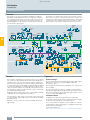
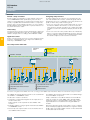
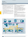
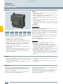
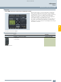
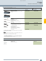
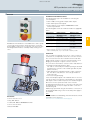
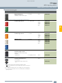
■ Overview
AS-Interface is a single master system. For automation systems
from Siemens, there are communications processors (CPs) communications modules (CMs) and network transitions (links) that
control the process or field communication as masters, and actuators and sensors that are activated as AS-Interface slaves.
AS-Interface is an open, international standard according to
EN 50295 and IEC 62026-2 for process and field communication. Leading manufacturers of actuators and sensors all over
the world support the AS-Interface. Interested companies are
provided with the electrical and mechanical specifications by
the AS-Interface Association.
Laptop
Telecontrol and
substation
control
PC
Remote access,
e.g. via
teleservice
S7-1200 with
CP 1242-7
Numeric Control
Controller
Controller
Control and
monitoring system
Motion Control
Systems
IWLAN
Controller
Security
PROFINET
Industrial Ethernet
Access
Point
Controller
Controller
Notebook
PC/PG
Access
Point
Industrial Ethernet
Switches
IWLAN
RCoax Cable
Controller
Field device for
intrinsically safe area
PC/PG/IPC
Control and
monitoring system
Numeric
Control
Wireless
Devices
Coupler
Link
PROFIBUS
PROFIBUS PA
RF180C
ASM456
Field devices
Mobile
Panel
Field devices
SIMOCODE
pro
RFID
system
Code
reading
systems
Mobile
Panel
DP-Slave
Drives
RFID
system
IO-Link
master
Motion Control
Systems
Code
reading
systems
Access
Point
Link
IO-Link
module
IO-Link
module
Power
supply
LOGO!
Compact
starter
Protection and
monitoring
devices
RFID system
Controller
SINAMICS
Drives
Link
Power
supply
Protection and
monitoring
devices
RFID system
Client
Module
Compact
starter
AS-Interface
Compact Compact
starter
feeder
Slaves
Field device
Slaves
Signalling column
■ Benefits
G_IK10_XX_20002
4
PC/PG/IPC
Database
Server
Telecontrol and
substation control
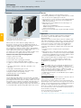
■ Application
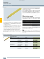
A key feature of AS-Interface technology is the use of a shared
two-conductor cable for data transmission and the distribution of
auxiliary power to the sensors/actuators. A power supply unit
which meets the requirements of the AS-Interface transmission
method and has an external data decoupling module if required
is used for the distribution of auxiliary power. The AS-Interface
cable used for the wiring is mechanically coded and hence protected against polarity reversal and can be easily contacted by
the insulation piercing method.
Elaborately wired control cables in the control cabinet and marshalling racks can be replaced by AS-Interface.
The AS-Interface cable can be connected to any points thanks
to a specially developed cable and connection by the insulation
piercing method.
With this concept you become extremely flexible and achieve
high savings.
I/O data exchange
The AS-i master transmits automatically the inputs and outputs
between the control system and the digital and analog
AS-Interface slaves.
Slave diagnostics information is forwarded to the control system
when required.
The latest AS-Interface masters according to the AS-Interface
Specification V3.0 support integrated analog value processing.
This means that data exchange with analog AS-Interface slaves
is just as easy as with digital slaves.
Command interface
In addition to I/O data exchange with binary and analog
AS-Interface slaves the AS-Interface masters provide a number
of other functions through the command interface.
Hence it is possible, for example, for slave addresses to be issued, parameter values transferred or configuration information
read out from user programs.
For more information see
http://support.automation.siemens.com/WW/view/en/51678777.
4/2
Siemens IK PI · 2015
© Siemens AG 2014
AS-Interface
Introduction
System components
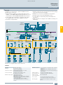
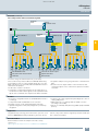
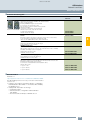
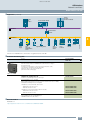
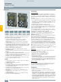
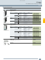
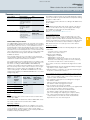
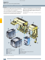
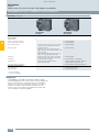
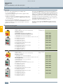
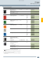
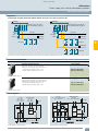
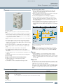
■ Overview
To implement communication, a system installation has the
following main components:
• Master interface modules for central control units such as
SIMATIC S7, ET 200/ET 200SP distributed peripherals, or network transitions from PROFIBUS/PROFINET to AS-Interface
• Power supply units, if required in combination with a data
decoupling module for the power supply to the slaves
• AS-Interface shaped cables
• Network components such as repeaters and extension plugs
(cannot be used for AS-i Power24V)
• Modules for connection of standard sensors/actuators
• Actuators and sensors with integrated AS-i slave
• Secure modules for transferring safety-related data over
AS-Interface
• Addressing units for setting the slave addresses during commissioning
SIMATIC/
SIMOTION
SINUMERIK
4
PROFINET
Industrial Ethernet
DP/AS-i F-Link
S7-300
CP 343-2(P)
AS-Interface
power supply
CM AS-i Master ST
for ET 200SP
DP/AS-i LINK Advanced
DP/AS-i Link 20E
S7-300
CP343-2(P)
AS-Interface
power supply
S7-200
with CP 243-2
S7-1200
with CM 1243-2
IE/AS-i LINK PN IO
AS-Interface
Digital and analog
K20, K45, K60 field modules
Safety switch
without
with
tumbler tumbler
Safe
EMERGENCY-STOP
and field module
PROFIBUS DP
Signaling
columns
Pushbuttons
Indicator lights
Safe and standard control cabinet
modules S22.5 and S45
24 V DC
power
supply
MSS
Advanced
MSS
ASIsafe
3RA2 load
feeders
SIRIUS
M200D motor
starters or
G110D
inverters
3RA6
compact
starters
G_IK10_XX_20027j
Load feeders
with safe
AS-i outputs
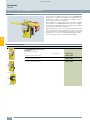
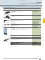
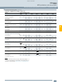
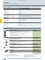
Example of a configuration with the system components
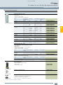
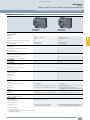
Features
Standard
EN 50295 / IEC 62026-2
Topology
Line, star or tree structure
(same as electrical wiring)
Transmission medium
Unshielded two-wire cable (2 x 1.5 mm2)
for data and auxiliary power
Connection methods
Contacting of the AS-Interface cable
by insulation piercing method
Maximum cable length •
•
•
•
100 m without repeater
200 m with extension plug
300 m with two repeaters in series connection
600 m with extension plugs and two repeaters
connected in parallel
Larger cable lengths are also possible
when additional repeaters are connected in
parallel
Maximum cycle time
• 5 ms in maximum configuration with 31 standard
addresses
• 10 ms in maximum configuration with 62 A/B
addresses
• profile-specific for slaves with extended data, e.g.
analog slaves
Number of stations
per AS-Interface line
• Up to 62 Slaves (A/B technology)
• Integrated analog value transmission
Number of binary
sensors and actuators
Max. 496 DI/496 DO
Access control
• Cyclic polling master/slave procedure
• Cyclic data acceptance from host (PLC, PC)
Error safeguard
Identification and repetition of faulty message
frames
Siemens IK PI · 2015
4/3
© Siemens AG 2014
AS-Interface
Introduction
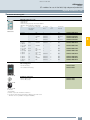
AS-Interface specification
Specification V3.0
■ Overview
■ More information
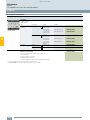
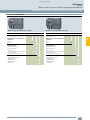
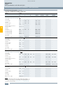
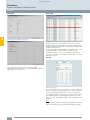
Scope of the AS-Interface specification
AS-Interface system manual
Maximum number of slaves
Number of
digital inputs
Number of
digital outputs
Digital
Analog
ASIsafe
DI
DO
62
62
31
62 8 = 496
62 8 = 496
Basic data
4
AS-Interface Specification 3.0 describes a fieldbus system with
an AS-i master and up to 62 AS-i slaves.
• The standard slaves continue to occupy one AS-i address
(1...31).
• Slaves with extended addressing divide an address into an
A address (1A...31A) and a B address (1B...31B). Up to 62
A/B slaves can be connected accordingly to one AS-Interface
network.
• Mixed operation of standard slaves and A/B slaves is possible
without difficulty. The AS-i master identifies automatically
which type of slave is connected. No special adjustments are
required of the user.
• A digital AS-i slave has up to 4 digital inputs and 4 digital
outputs.
• Transmission of digital input/output data requires a cycle time
of max. 5 ms with 31 slaves, see "Communication cycle" for
further values.
• Integrated analog value transmission permits access to both
analog values and digital values without the need for any
special function blocks.
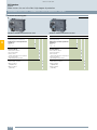
Communication cycle
Maximum cycle time (digital signals)
•
•
•
•
5 ms with 31 slaves
10 ms with 62 slaves
Up to 20 ms for A/B slaves with 4DI/4DO
Up to 40 ms for A/B slaves with 8DI/8DO
Each address is queried in max. 5 ms cycle time. If two A/B
slaves are operated on one basic address (e.g. 12A and 12B), a
maximum 10 ms will be required for updating the data of both
slaves.
All slave types can be mixed and used on a single AS-Interface
network.
For more information, for example, to find out whether an
AS-Interface slave is a standard or A/B slave, refer to "Selection
and ordering data" of the relevant slave.
Available masters with the latest AS-Interface specification V3.0
• CP 343-2, CP 343-2P (S7-300 / ET 200M)
• DP/AS-i LINK Advanced
• DP/AS-i F-Link
• DP/AS-Interface Link 20E
• IE/AS-i LINKPNIO
• CM 1243-2 (S7-1200)
• CM AS-i Master ST (ET 200SP)
4/4
Siemens IK PI · 2015
The AS-Interface system manual is available as a free download.
• German
http://support.automation.siemens.com/WW/view/de/26250840
• English
http://support.automation.siemens.com/WW/view/en/26250840
© Siemens AG 2014
AS-Interface
Introduction
AS-Interface specification
AS-i Power24V expansion
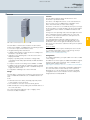
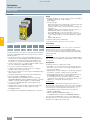
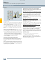
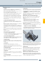
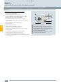
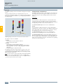
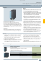
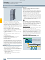
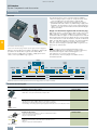
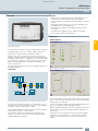
■ Overview
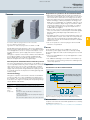
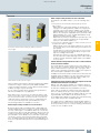
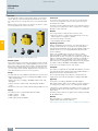
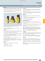
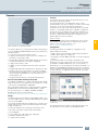
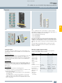
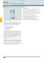
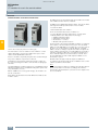
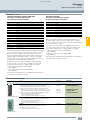
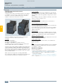
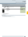
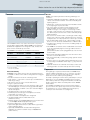
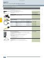
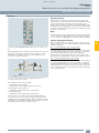
AS-Interface data decoupling modules for AS-i Power24V,
left: S22.5 data decoupling module,
right: DCM 1271 data decoupling module for SIMATIC S7-1200
Parallel wiring frequently dominates, above all, in applications
with very few I/Os. Although AS-Interface is similarly well suited
for small applications, its use is often prevented by the cost of
the 30 V AS-Interface power supply unit which is required in
addition.
Through the expansion of AS-Interface with AS-i Power24V and
the resulting possibility of using existing standard 24 V DC
power supply units in AS-i networks, AS-Interface is now also
attractive for applications with a very tight budget.
Data and power in standard AS-Interface networks up to now
One of the great advantages of AS-Interface is the ability to convey not only data, but also the power needed for the connected
slaves and sensors over the same unshielded two-conductor
cable. This is owed to the service-proven AS-Interface power
supply units which provide integrated data decoupling as well
as overload and short-circuit protection and integrated groundfault monitoring.
Requirements for operation of an AS-i Power24V network
• When 24 V power supply units are used, the maximum network range of 50 m must be observed in order to reach slaves
and sensors with a sufficient level of voltage (at least 18 V).
• The power supply units must comply with the PELV (Protective
Extra Low Voltage) or SELV (Safety Extra Low Voltage) standards, have a residual ripple of < 250 mVpp, and in the event
of a fault must limit the output voltage to a maximum of 40 V.
SITOP power supply units are recommended, see Catalog
IC 10, Chapter 15 "Products for Specific Requirements"
"Stabilized Power Supplies".
• When used in conjunction with standard 24 V power supply
units, each AS-Interface network requires Power24V-capable
data decoupling with adapted ground-fault detection, see
page 4/75.
• For reliable operation of an AS-i network with 24 V voltage, it is
important that the masters, slaves and other components are
approved for AS-i Power24V. AS-i Power24V-capable AS-i
components can also be used without restriction in standard
30 V AS-i networks.
• The use of repeaters or extension plugs in AS-i Power24V
networks is not permitted.
■ Benefits
AS-i Power24V networks incur no additional costs for an
AS-Interface power supply unit because an already existing
24 V power supply unit can be used. This brings the user several
benefits:
• The level of standardization of very small applications can be
increased further.
• The additional advantages of a modern communication system in terms of commissioning, maintenance and diagnostics
can be fully exploited.
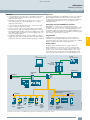
■ Application
Construction of an AS-i Power24V network
PROFINET
The new technology
S7-1200 with DCM 1271, CM 1243-2
and 24 V standard power supply unit
Through the expansion of AS-Interface with AS-i Power24V it is
now also possible to use 24 V standard power supply units in
AS-i networks. The communication technology of AS-Interfaces
works at the same high level of quality with an operating voltage
of both 30 V DC and 24 V DC.
Up to 50 m
Key data of AS-i Power24V
Up to 62 standard slaves and up to 31 safe slaves
Topology
Any
Range
Up to 50 m
Components
• 24 V power supply unit with little residual ripple and
imitation to max. 40 V
• AS-i Power24V-capable data decoupling with integrated
ground-fault detection
• AS-i Power24V-capable masters, slaves and components
AS-Interface
I/O modules
NSB0_02245
Number of
slaves
Construction of an AS-i Power24V network with an AS-Interface
DCM 1271 data decoupling module and S7-1200 (simple network)
■ More information
Complete overview of AS-i Power24V-capable devices currently
available from Siemens see
http://support.automation.siemens.com/WW/view/en/42806066.
Siemens IK PI · 2015
4/5
4
© Siemens AG 2014
AS-Interface
ASIsafe
Introduction
■ Overview
ASIsafe – Safety is included
Configuring safety functions
ASIsafe enables the integration of safety-related components,
such as EMERGENCY-STOP pushbuttons, protective door
switches or safety light arrays, in an AS-Interface network. These
are fully compatible with the familiar AS-Interface components
(masters, slaves, power supplies, repeaters, etc.) in accordance
with IEC 62026-2 and are operated in conjunction with them on
the yellow AS-Interface cable.
In order to implement safe functions, the information from the
safe and standard nodes must be combined logically and further parameters set. The configuration of the safety functions depends on which safety solution is being used:
• In the case of the AS-i safety solution with F-CPU: In conjunction with the SIMATIC AS-i F-Link as a safe AS-i master, all
safety functions and logic operations are configured via STEP
7 and processed in the controller (F-CPU) by the fail-safe program.
• In the case of the AS-i safety solution with local evaluation by
MSS: In conjunction with the Modular Safety System, all safety
functions and logic operations are configured using the MSS
ES software and processed in the MSS central unit.
Tested safety
The transmission method for safety-related signals is approved
for implementing applications up to PL e according to EN ISO
13849-1 and up to SIL 3 according to IEC 62061/IEC 61508.
Higher-level control
Nodes on the AS-Interface bus are as usual controlled in operation by the standard program of the higher-level SIMATIC (F)
CPU or by a SINUMERIK control.
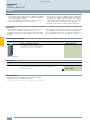
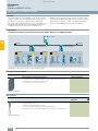
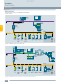
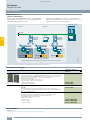
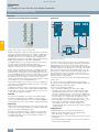
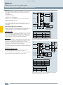
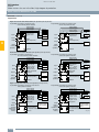
AS-i safety solution with F-CPU
Operational
control
Safety-oriented
processing
Safe control
SIMATIC S7-300F
PROFINET / PROFIsafe
SIMATIC
AS-i F-Link
SIMATIC
AS-i F-Link
AS-Interface / ASIsafe
AS-Interface / ASIsafe
AS-Interface / ASIsafe
IC01_00288
4
1
2
3
4
5
6
1
2
3
4
5
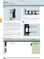
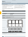
1 Safe EMERGENCY-STOP
4 Load feeder with safe AS-i outputs
2 Safe position switch with door interlock
5 Digital K45 field module
3 Field module
6 3RA2 load feeder
6
1
2
3
4
5
6
AS-Interface configuration with SIMATIC AS-i F-Link, consisting of an ET 200SP station with CM AS-i Master ST and F-CM AS-i Safety ST modules
The SIMATIC AS-i F-Link allows AS-Interface to be used with failsafe SIMATIC or SINUMERIK controls.
The SIMATIC AS-i F-Link is implemented as a modular arrangement of ET 200SP components.
The allocation of tasks is as follows:
• Acquisition of safety-related signals via safe input slaves on
the AS-Interface bus.
Further signals can be acquired via other SIMATIC F-DI
modules.
• Evaluation and processing of signals via the fail-safe SIMATIC
or SINUMERIK control
• Reaction by safe output modules on the AS-Interface bus or
other SIMATIC F-DQ modules
Simple combination of the CM AS-i Master ST and F-CM AS-i
Safety ST modules in one ET 200SP station with PROFINET
interfacing results in a powerful PN/AS-i F-Link, which can be
expanded further in a modular fashion using ET 200SP I/O
modules.
4/6
Siemens IK PI · 2015
Using these design methods, it is possible to create configurations for virtually any application. Besides the single AS-i master,
double, triple or generally multiple masters can be realized with
or without fail-safe functionality.
© Siemens AG 2014
AS-Interface
ASIsafe
Introduction
■ Overview (continued)
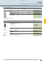
AS-i safety solution with local evaluation by MSS
Operational
control
Controls
e. g. SIMATIC S7-300
PROFINET
PROFIBUS
Safety-oriented
processing
Safety-oriented
processing
AS-Interface / ASIsafe
2
3
4
MSS
AS-Interface / ASIsafe
5
6
2
1
3
4
4
Safety-oriented
processing
MSS
MSS
1
DP/AS-i LINK Advanced
SIMATIC S7-1200
AS-Interface / ASIsafe
5
6
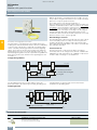
1 Safe EMERGENCY-STOP
4 Load feeder with safe AS-i outputs
2 Safe position switch with door interlock
5 Digital K45 field module
3 Fieldmodule
6 3RA2 load feeder
1
2
3
4
5
6
IC01_00167a
Operational
control
IE/AS-i LINK PN IO
AS-Interface design with 3RK3 Modular Safety System (MSS)
The local AS-i safety solution utilizes the 3RK3 Modular Safety
System (MSS) to process safety-related signals. Use of a standard controller (i.e. not an F-CPU) and a standard AS-i master is
sufficient for this purpose.
The allocation of tasks is as follows:
• Acquisition of safety-related signals via safe input slaves on
the AS-Interface bus. Further signals can be acquired via F-DI
inputs of the central unit or the expansion modules of the MSS.
• Acquisition and processing of signals via the central unit of the
MSS
• Reaction via safe output modules on the AS-Interface bus
of via F-DQ outputs of the central unit or expansion modules
of the MSS
■ Benefits
• Easy plant configuration thanks to standardized AS-Interface
technology
• Safety-related and standard data on the same bus
• Existing systems can be expanded quickly and easily
• Optimum integration in TIA (Safety Diagnostics) and Safety
Integrated
• Inclusion of the safety signals in the plant diagnostics, also on
existing HMI panels
• Approved to PL e according to EN ISO 13849-1 or SIL 3
according to IEC 61508
• ASIsafe is certified by TÜV (Germany), NRTL (USA) and INRS
(France)
■ Application
Integrated safety technology in the AS-Interface system is used
wherever EMERGENCY-STOP pushbuttons, protective door in-
terlocks, safe position switches, light arrays and two-hand operator controls are installed.
■ More information
More information and circuit examples relevant to safety
systems see
http://support.automation.siemens.com/WW/view/en/20208582.
Siemens IK PI · 2015
4/7
© Siemens AG 2014
AS-Interface
ASIsafe
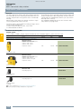
AS-Interface safety monitors
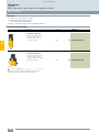
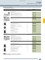
■ Selection and ordering data
Version
Article No.
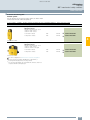
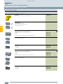
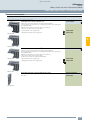
Basic safety monitor
Version 3
With screw terminals, removable terminals,
width 45 mm
Screw terminals
• One enabling circuit (monitor type 1)
3RK1105-1AE04-0CA0
• Two enabling circuits (monitor type 2)
3RK1105-1BE04-0CA0
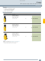
Expanded safety monitors
Version 3
With screw terminals, removable terminals,
width 45 mm
3RK1105-1BE04-0CA0
• One enabling circuit (monitor type 3)
3RK1105-1AE04-2CA0
• Two enabling circuits (monitor type 4)
3RK1105-1BE04-2CA0
Expanded safety monitors with integrated safe slave
Version 3
With screw terminals, removable terminals, width 45 mm
4
• Two enabling circuits including control of a safe AS-i output /
safe coupling (monitor type 6)
3RK1105-1BE04-4CA0
Basic safety monitors
Version 3
With spring-type terminals, removable terminals,
width 45 mm
Spring-type terminals
• One enabling circuit (monitor type 1)
3RK1105-1AG04-0CA0
• Two enabling circuits (monitor type 2)
3RK1105-1BG04-0CA0
Expanded safety monitors
Version 3
With spring-type terminals, removable terminals,
width 45 mm
• One enabling circuit (monitor type 3)
3RK1105-1AG04-2CA0
• Two enabling circuits (monitor type 4)
3RK1105-1BG04-2CA0
Expanded safety monitor with integrated safe slave
Version 3
With spring-type terminals, removable terminals,
width 45 mm
• Two enabling circuits including control of a safe AS-i output /
safe coupling (monitor type 6)
3RK1105-1BG04-4CA0
ASIsafe CD
3RK1802-2FB06-0GA1
Accessories
Included in the scope of supply:
• ASIMON V3 configuration software on CD ROM, for PC with the
32-bit operating systems Windows XP, Windows Vista Business/Ultimate, Windows 7
Cable sets
3RK1901-5AA00
Included in the scope of supply:
• PC configuration cable for communication between PC (serial interface) and
safety monitor,
length approx. 1.50 m
• Transfer cable between two safety monitors,
length approx. 0.25 m
3RK1901-5AA00
4/8
Sealable covers
For securing against unauthorized configuration of the safety monitor
3RP1902
Push-in lugs
For screw fixing
3RP1903
Siemens IK PI · 2015
© Siemens AG 2014
AS-Interface
ASIsafe
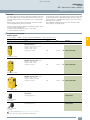
AS-Interface safety modules
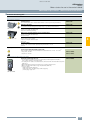
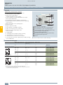
■ Overview
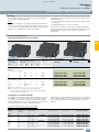
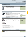
K45F compact safety modules for use in the field
AS-Interface safety modules: K45F (left), K20F (center) and
S22.5F (right)
The platform of the K45F modules covers the following variations:
• Connection of ("mechanical") switches/safety sensors
with contacts:
- K45F 2F-DI: Two safety-related inputs in operation up to
Category 2 according to EN ISO 13849-1. If Category 4 is
required, a two-channel input is available on the module.
- K45F 2F-DI/2DO: There are also two standard outputs in addition to the safe inputs. Supplied from the yellow AS-i cable
- K45F 2F-DI/2DO Uaux: same as K45F 2F-DI/2DO, but supplied from the black 24 V DC cable
- K45F 4F-DI: Four safety-related inputs in operation up to Category 2, two for Category 4. Extremely compact double
slave (uses two full AS-i addresses).
• Connection of solid-state switches / safety sensors (non-contact protective devices, ESPE):
- K45F LS (light sensor): Safe input module for the connection
of electronic safety sensors with testing semiconductor outputs (OSSD)
In particular non-contact protective devices such as active,
optoelectronic light arrays and light arrays for Type 2 and
Type 4 according to IEC 61496.
Transmitters as well as receivers are supplied with power
from the yellow AS-i cable. Matching sensor cables and optionally a separate transmitter supply module are available
as accessories.
S22.5F SlimLine safety modules for use in control cabinets
and local control cabinets
The S22.5F SlimLine safety module has two safety inputs. The
safe connection of signals to ASIsafe networks in the cabinet is
also possible therefore. For operation up to Category 2, both
inputs can be separately assigned; if Category 4 is required, a
two-channel input is available on the module.
In addition there are two S22.5F module versions which have two
standard outputs in addition to the two safety inputs; power is
supplied either from only the yellow AS-Interface cable or as
auxiliary voltage from the black 24 V DC cable.
S45F SlimLine module, safe AS-i output
Safety modules for AS-Interface (ASIsafe modules) are available
for field use in degree of protection IP67 (K20F and K45F
compact modules) and for the control cabinet (S22.5F SlimLine
modules) in degree of protection IP20.
A very compact module with an optimum price/performance
ratio is thus available for very application.
All modules for the connection of (mechanical) switches and
safety sensors with contacts feature cross-circuit monitoring of
the connected sensor line. On versions for the connection of
solid-state switches and safety sensors (e.g. light arrays) the
cross-circuit monitoring must be performed by the sensor.
The following modules are available for selection:
K20F compact safety modules for use in the field
S45F SlimLine safety modules with safe outputs for the safe
distributed disconnection of actuators
With the safe S45F SlimLine-Module, the shutdown signal, for
example from the Modular Safety System, can be used through
the ASIsafe for distributed safety-related disconnection.
To this end, the module has a dual-channel relay output with
which an enabling circuit up to safety category 4 and Performance Level e according to EN ISO 13849-1 and SIL 3 according to EN 62061 / IEC 61508 can be deactivated safely.
As an additional possibility the module offers normal switching
of the output using an AS-i standard output bit.
The module has three digital inputs and two digital outputs for
the additional connection of sensors and actuators. These can
be used, inter alia, for the necessary monitoring of downstream
contactors of the feedback circuit.
Being only 20 mm wide, the K20F module is particularly well
suited for applications where modules need to be arranged in
the most confined space. The K20F modules are connected to
the AS-Interface with a round cable with M12 cable box instead
of with the AS-Interface flat cable. This enables extremely compact installation. The flexibility of the round cable means that it
can also be used on moving machine parts without any problems. The K20 modules are also ideal for such applications as
their non-encapsulated design makes them particularly light in
weight.
Siemens IK PI · 2015
4/9
4
© Siemens AG 2014
AS-Interface
ASIsafe
AS-Interface safety modules
■ Selection and ordering data
Version
Article No.
K20F compact safety modules
I/O type
Uaux 24 V
2 F-DI
--
3RK1205-0BQ30-0AA3
3RK1205-0BQ30-0AA3
K45F compact safety modules
Modules supplied without mounting plate
3RK1205-0BQ00-0AA3
4
I/O type
Uaux 24 V
2 F-DI
--
3RK1205-0BQ00-0AA3
4 F-DI1)
--
3RK1205-0CQ00-0AA3
2 F-DI / 2 DO
--
3RK1405-0BQ20-0AA3
2 F-DI / 2 DO
3RK1405-1BQ20-0AA3
2 F-DI LS type 22)
--
3RK1205-0BQ21-0AA3
2 F-DI LS type 43)
--
3RK1205-0BQ24-0AA3
S22.5F SlimLine safety modules
Connection
I/O type
Uaux 24 V
Screw
2 F-DI
--
3RK1205-0BE00-0AA2
2 F-DI / 2 DO
--
3RK1405-0BE00-0AA2
2 F-DI / 2 DO
3RK1405-1BE00-0AA2
2 F-DI
--
3RK1205-0BG00-0AA2
2 F-DI / 2 DO
--
3RK1405-0BG00-0AA2
2 F-DI / 2 DO
3RK1405-1BG00-0AA2
Spring-type
3RK1205-0BE00-0AA2
S45F SlimLine safety module
Connection
I/O type
Uaux 24 V
Screw
1F-RO/3DI/2DO
3RK1405-1SE15-0AA2
Spring-type
1F-RO/3DI/2DO
3RK1405-1SG15-0AA2
3RK1405-1SE15-0AA2
Available or possible
-- Not available or not possible
1)
Module occupies two AS-Interface addresses
2)
Connection of previous Siemens light curtain FS 400 3RG7843 (type 2)
through socket 1/3.
3)
Connection of previous Siemens light curtain FS 400 3RG7846 (type 4)
through socket 1/3, other makes through socket 2/3.
4/10
Siemens IK PI · 2015
© Siemens AG 2014
AS-Interface
ASIsafe
AS-Interface safety modules
■ Accessories
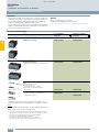
Version
Article No.
K45 mounting plates
For mounting K45F
• For wall mounting
3RK1901-2EA00
• For standard rail mounting
3RK1901-2DA00
24 V supply modules for K45F LS (light sensor)
3RK1901-1NP00
3RK1901-2EA00
• Optional, for transmitter power supply for large protective field widths
• Max. current carrying capacity 200mA
• Modules supplied without mounting plate
Input bridges for K45F
3RK1901-1AA00
• Black version
3RK1901-1AA00
• Red version
3RK1901-1AA01
AS-Interface M12 sealing caps
For free M12 sockets
3RK1901-1KA00
AS-Interface M12 sealing caps, tamper-proof
For free M12 sockets
3RK1901-1KA01
4
3RK1901-1KA00
3RK1901-1KA01
Siemens IK PI · 2015
4/11
© Siemens AG 2014
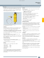
AS-Interface
ASIsafe
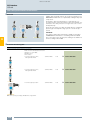
3SF1 mechanical safety switches
■ Overview
The 3SF1 position switches with safety-related communication
can be directly connected using the AS-Interface bus system.
The safety functions no longer have to be conventionally wired
up.
With the 3SF1 position switches the ASIsafe electronics component is integrated in the switch enclosure.
Connection
Connection to the AS-Interface is by means of a 4-pole M12
connector socket (plastic version) connected to the yellow
AS-Interface bus cable.
The wide enclosures (50 or 56 mm) also have an M12 socket for
connecting a second position switch. Category 4 according to
EN 954-1 is thus achieved.
Benefits
The new generation of 3SF1 position switches offers:
• ASIsafe electronics component integrated in the enclosure,
with low power consumption < 60 mA
• An extensive range of actuators
• Status display with three LEDs
4
Operating conditions
With the standard position switches, mechanical positions of
moving machine parts are converted into electrical signals.
Through their modular and uniform design and large number of
variants, the devices can comply with practically all requirements in industry.
Examples of selection options in the modular system
Modular system
The position switches of the 3SF11.4 and 3SF12.4 series are designed as a modular system comprising different versions of the
basic switch and an actuator which must be ordered separately.
Thanks to the modular design of the switch the end users can
select the right solution for their application from numerous versions and install it themselves in a very short time.
Design
The 3SF1 switches are available in four different enclosure sizes:
• Plastic and metal enclosures according to EN 50047, 31 mm
wide, with M12 plug
• Metal enclosures according to EN 50041, 40 mm wide, with
M12 plug
• Plastic enclosures, 50 mm wide, with M12 plug and M12
socket
• Metal enclosures, 56 mm wide, with M12 plug and M12 socket
Display
The switches have a status display with three LEDs:
• LED 1 (yellow):
F-IN1
• LED 2 (yellow):
F-IN2
• LED 3 (green/red): AS-i/FAULT
4/12
Siemens IK PI · 2015
Devices are available with enclosure versions to suit the
particular ambient conditions. Different control tasks can be
performed with the best contact blocks suited for the particular
purpose. And many different actuator variants are available to
match the mechanical configuration of the moving machine
parts. Dimensions, fixing points and characteristics are largely in
accordance with the EN 50041 or EN 50047 standards.
The devices are suitable for use in any climate.
Standards
The switches comply with the standards IEC 60947-1 (Low-Voltage Switchgear and Controlgear, General) and IEC 60947-5-1
(Electromechanical Control Circuit Devices).
The mechanical design of the switches corresponds to the
requirements of the fail-safe principle according to EN 1088.
Approvals
AS-Interface according to EN 50295 and IEC 62026-2.
With a 3SF1 position switch it is possible to achieve Category 2
according to ISO 13849-1 or SIL 1 according to IEC 61508.
Categories 3 or 4 according to ISO 13849-1 or SIL 2 or 3 according to IEC 61508 can be achieved by using a second 3SE5 position switch.
The 3SF1 position switches are approved according to UL 508,
UL 50 and UL 746-C.
Manuals
More information see configuration manual
"SIRIUS 3SE5 / 3SF1 Position Switches"
http://support.automation.siemens.com/WW/view/en/43920150
http://support.automation.siemens.com/WW/view/en/43920150
© Siemens AG 2014
AS-Interface
ASIsafe
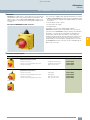
3SF1 mechanical safety switches
Plastic enclosures
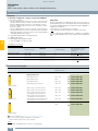
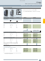
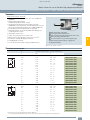
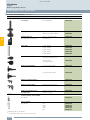
■ Selection and ordering data
Modular system
For the ASIsafe version of the position switch, the basic switch
and actuator must be ordered separately.
1 or 2 contacts · 3 LEDs · Degree of protection IP65 (31 mm) or IP66/IP67 (50 mm) · M12 connector socket
Version
Contacts
LEDs
Article No.
Basic switches (with rounded plunger1)) · Enclosure width 31 mm acc. to EN 50047
With Teflon plunger,
with M12 connector socket, 4-pole
channel 1 on NC contact,
channel 2 on NC contact
• Slow-action contacts
2 NC
24 V DC
q
3SF1234-1KC05-1BA1
• Snap-action contacts
2 NC
24 V DC
q
3SF1234-1LC05-1BA1
4
ASIsafe basic switch
Basic switches (with rounded plunger1)) · Enclosure width 50 mm
With Teflon plunger,
with M12 connector socket, 4-pole
channel 1 on NC contact,
channel 2 on M12 socket, right
• Slow-action contacts
1 NC
24 V DC
q
3SF1244-1KC05-1BA2
• Snap-action contacts
1 NC
24 V DC
q
3SF1244-1LC05-1BA2
ASIsafe basic switch
For online configurator see www.siemens.com/sirius/configurators.
q Positive opening according to IEC 60947-5-1, Appendix K, or
positively driven actuator for use in safety circuits.
1)
For enclosures with widths of 31 mm and 50 mm, the basic switch is a
complete unit with rounded plungers.
Siemens IK PI · 2015
4/13
© Siemens AG 2014
AS-Interface
ASIsafe
3SF1 mechanical safety switches
Plastic enclosures
■ Selection and ordering data (continued)
Version
Diameter
Article No.
mm
Operating mechanisms
Roller plungers, type C acc. to EN 50047
Roller plunger
• Plastic roller
10
q
3SE5000-0AD03
• High-grade steel roller
10
q
3SE5000-0AD04
• Plastic roller
10
q
3SE5000-0AD10
• High-grade steel roller
10
q
3SE5000-0AD11
• Metal lever, plastic roller
13
q
3SE5000-0AE10
• Metal lever, high-grade steel roller
13
q
3SE5000-0AE11
• High-grade steel lever, plastic roller
13
q
3SE5000-0AE12
• High-grade steel lever, high-grade steel roller
13
q
3SE5000-0AE13
• Metal lever, plastic roller
13
q
3SE5000-0AF10
• Metal lever, high-grade steel roller
13
q
3SE5000-0AF11
• High-grade steel lever, plastic roller
13
q
3SE5000-0AF12
• High-grade steel lever, high-grade steel roller
13
q
3SE5000-0AF13
q
3SE5000-0AK00
Roller plungers
with central fixing
With central fixing
Roller levers, type E acc. to EN 50047
4
Roller lever
Angular roller levers
Angular roller lever
Twist actuators with lever
Twist actuators,
plastic (without lever)
Switching right or left,
adjustable
Twist actuator
Lever for twist actuators
Twist levers, type A acc. to EN 50047
Twist lever
• Metal lever, plastic roller
19
q
3SE5000-0AA21
• Metal lever, high-grade steel roller
19
q
3SE5000-0AA22
• Metal lever, roller with ball bearing
19
q
3SE5000-0AA23
• Metal lever, plastic roller
30
q
3SE5000-0AA25
• High-grade steel lever, plastic roller
19
q
3SE5000-0AA31
• High-grade steel lever, high-grade steel roller
19
q
3SE5000-0AA32
• Metal lever, plastic roller
19
q
3SE5000-0AA24
• Metal lever, plastic roller
30
q
3SE5000-0AA26
• Metal lever, plastic roller
19
q
3SE5000-0AA60
• Metal lever, high-grade steel roller
19
q
3SE5000-0AA61
• Metal lever, plastic roller
50
q
3SE5000-0AA67
• Metal lever, rubber roller
50
q
3SE5000-0AA68
• High-grade steel lever, plastic roller
19
q
3SE5000-0AA62
• High-grade steel lever, high-grade steel roller
19
q
3SE5000-0AA63
Twist levers,
length 30 mm, straight1)
Twist levers,
adjustable length, with grid hole
Twist lever,
adjustable length
q Positively driven actuator, for use in safety circuits.
1)
Can be clinch mounted (turned through 180°, rear of lever).
4/14
Siemens IK PI · 2015
© Siemens AG 2014
AS-Interface
ASIsafe
3SF1 mechanical safety switches
Metal enclosures
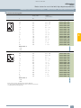
■ Selection and ordering data
Modular system
For the ASIsafe version of the position switch, the basic switch
and actuator must be ordered separately.
2 contacts · 3 LEDs · Degree of protection IP66/IP67 · M12 connector socket
Version
Contacts
LEDs
Article No.
Basic switches (with rounded plunger1)) · Enclosure width 31 mm acc. to EN 50047
With Teflon plunger,
with M12 connector socket, 4-pole
channel 1 on NC contact,
channel 2 on NC contact
• Slow-action contacts
2 NC
24 V DC
q
3SF1214-1KC05-1BA1
• Snap-action contacts
2 NC
24 V DC
q
3SF1214-1LC05-1BA1
4
ASIsafe basic switch
For online configurator see www.siemens.com/sirius/configurators.
q Positive opening according to IEC 60947-5-1, Appendix K, or
positively driven actuator for use in safety circuits.
1)
For enclosures with widths of 31 mm, the basic switch is a complete unit
with rounded plungers.
Siemens IK PI · 2015
4/15
© Siemens AG 2014
AS-Interface
ASIsafe
3SF1 mechanical safety switches
Metal enclosures
■ Selection and ordering data (continued)
Version
Diameter
Article No.
mm
Operating mechanisms
Plain plungers
• High-grade steel plungers
10
q
3SE5000-0AB01
• Plastic roller
10
q
3SE5000-0AD03
• High-grade steel roller
10
q
3SE5000-0AD04
• Plastic roller
10
q
3SE5000-0AD10
• High-grade steel roller
10
q
3SE5000-0AD11
13
q
3SE5000-0AE10
• Metal lever, high-grade steel roller
13
q
3SE5000-0AE11
• High-grade steel lever, plastic roller
13
q
3SE5000-0AE12
• High-grade steel lever, high-grade steel roller
13
q
3SE5000-0AE13
• Metal lever, plastic roller
13
q
3SE5000-0AF10
• Metal lever, high-grade steel roller
13
q
3SE5000-0AF11
• High-grade steel lever, plastic roller
13
q
3SE5000-0AF12
• High-grade steel lever, high-grade steel roller
13
q
3SE5000-0AF13
q
3SE5000-0AK00
Plain plungers
Roller plungers, type C acc. to EN 50047
Roller plunger
Roller plunger
with central fixing
4
With central fixing
Roller levers, type E acc. to EN 50047
• Metal lever, plastic roller
Roller lever
Angular roller levers
Angular roller lever
Twist actuators with lever
Twist actuators,
plastic (without lever)
Switching right or left,
adjustable
Twist actuator
Lever for twist actuators
Twist levers, type A acc. to EN 50047
Twist lever
• Metal lever, plastic roller
19
q
3SE5000-0AA21
• Metal lever, high-grade steel roller
19
q
3SE5000-0AA22
• Metal lever, roller with ball bearing
19
q
3SE5000-0AA23
• Metal lever, plastic roller
30
q
3SE5000-0AA25
• High-grade steel lever, plastic roller
19
q
3SE5000-0AA31
• High-grade steel lever, high-grade steel roller
19
q
3SE5000-0AA32
• Metal lever, plastic roller
19
q
3SE5000-0AA24
• Metal lever, plastic roller
30
q
3SE5000-0AA26
• Metal lever, plastic roller
19
q
3SE5000-0AA60
• Metal lever, high-grade steel roller
19
q
3SE5000-0AA61
• Metal lever, plastic roller
50
q
3SE5000-0AA67
• Metal lever, rubber roller
50
q
3SE5000-0AA68
• High-grade steel lever, plastic roller
19
q
3SE5000-0AA62
• High-grade steel lever, high-grade steel roller
19
q
3SE5000-0AA63
Twist levers,
length 30 mm, straight1)
Twist levers,
adjustable length, with grid hole
Twist lever,
adjustable length
q Positively driven actuator, for use in safety circuits.
1)
Can be clinch mounted (turned through 180°, rear of lever).
4/16
Siemens IK PI · 2015
© Siemens AG 2014
AS-Interface
ASIsafe
3SF1 mechanical safety switches
Metal enclosures
■ Selection and ordering data (continued)
Modular system
For the ASIsafe version of the position switch, the basic switch
and actuator must be ordered separately.
1 or 2 contacts · 3 LEDs · Degree of protection IP66/IP67 · M12 connector socket
Version
Contacts
LED
• Slow-action contacts
2 NC
24 V DC
q
3SF1114-1KA00-1BA1
• Snap-action contacts
2 NC
24 V DC
q
3SF1114-1LA00-1BA1
Article No.
Basic switches · Enclosure width 40 mm acc. to EN 50041
With M12 connector socket, 4-pole,
channel 1 on NC contact,
channel 2 on NC contact
4
ASIsafe basic switch
Basic switches · Enclosure width 56 mm
With M12 connector socket, 4-pole,
channel 1 on NC contact,
channel 2 on M12 socket, right
• Slow-action contacts
1 NC
24 V DC
q
3SF1124-1KA00-1BA2
• Snap-action contacts
1 NC
24 V DC
q
3SF1124-1LA00-1BA2
ASIsafe basic switch
For online configurator see www.siemens.com/sirius/configurators.
q Positive opening according to IEC 60947-5-1, Appendix K, or
positively driven actuator for use in safety circuits.
Version
Diameter
Article No.
mm
Operating mechanisms
Plain plungers
High-grade steel plungers
q
3SE5000-0AB01
q
3SE5000-0AC02
13
q
3SE5000-0AD02
• Metal lever, plastic roller
22
q
3SE5000-0AE01
• Metal lever, high-grade steel roller
22
q
3SE5000-0AE02
• High-grade steel lever, plastic roller
22
q
3SE5000-0AE03
• High-grade steel lever, high-grade steel roller
22+
q
3SE5000-0AE04
22
q
3SE5000-0AF01
• Metal lever, high-grade steel roller
22
q
3SE5000-0AF02
• High-grade steel lever, plastic roller
22
q
3SE5000-0AF03
• High-grade steel lever, high-grade steel roller
22
q
3SE5000-0AF04
Plain plunger
Rounded plungers, type B, acc. to EN 50041
High-grade steel plungers
Rounded plunger
Roller plungers, type C acc. to EN 50041
High-grade steel rollers
Roller plunger
Roller levers
Roller lever
Angular roller levers
• Metal lever, plastic roller
Angular roller lever
q Positively driven actuator, for use in safety circuits.
Siemens IK PI · 2015
4/17
© Siemens AG 2014
AS-Interface
ASIsafe
3SF1 mechanical safety switches
Metal enclosures
■ Selection and ordering data (continued)
Version
Diameter
Article No.
mm
Twist actuators with lever
Twist actuators, metal (without lever)
• Switching right or left, adjustable
q
3SE5000-0AH00
• For fork levers, latching
q
3SE5000-0AT10
Twist actuator
Lever for twist actuators
Twist levers 27 mm, type A, according to EN 50041
4
Twist lever
• Metal lever, plastic roller
19
q
3SE5000-0AA01
• Metal lever, high-grade steel roller
19
q
3SE5000-0AA02
• Metal lever, roller with ball bearing
19
q
3SE5000-0AA03
• Metal lever, 2 plastic rollers
19
q
3SE5000-0AA04
• Metal lever, plastic roller
30
q
3SE5000-0AA05
• Metal lever, plastic roller
50
q
3SE5000-0AA07
• Metal lever, rubber roller
50
q
3SE5000-0AA08
• High-grade steel lever, plastic roller
19
q
3SE5000-0AA11
• High-grade steel lever, high-grade steel roller
19
q
3SE5000-0AA12
• Metal lever, plastic roller
19
q
3SE5000-0AA15
• High-grade steel lever, plastic roller
19
q
3SE5000-0AA16
• Metal lever, plastic roller
19
q
3SE5000-0AA24
• Metal lever, plastic roller
30
q
3SE5000-0AA26
• Metal lever, plastic roller
19
q
3SE5000-0AA60
• Metal lever, high-grade steel roller
19
q
3SE5000-0AA61
• Metal lever, plastic roller
50
q
3SE5000-0AA67
• Metal lever, rubber roller
50
q
3SE5000-0AA68
• High-grade steel lever, plastic roller
19
q
3SE5000-0AA62
• High-grade steel lever, high-grade steel roller
19
q
3SE5000-0AA63
Twist levers,
length 35 mm, offset
Twist levers,
length 30 mm, straight1)
Twist levers,
adjustable length, with grid hole
Twist lever,
adjustable length
Fork levers (for switches with snap-action contacts only)
Fork lever
• 2 metal levers, 2 plastic rollers
19
q
3SE5000-0AT01
• 2 metal levers, 2 high-grade steel rollers
19
q
3SE5000-0AT02
• 2 high-grade steel levers, 2 plastic rollers
19
q
3SE5000-0AT03
• 2 high-grade steel levers, 2 high-grade steel rollers 19
q
3SE5000-0AT04
q Positively driven actuator, for use in safety circuits.
1)
Can be clinch mounted (turned through 180°, rear of lever).
4/18
Siemens IK PI · 2015
© Siemens AG 2014
AS-Interface
ASIsafe
3SF1 mechanical safety switches with separate actuator
■ Overview
The 3SF1 safety switches with safety-related communication can
be directly connected using the AS-Interface bus system. The
safety functions no longer have to be conventionally wired up.
With the 3SF1 safety switches the ASIsafe electronics component is integrated in the switch enclosure.
Connection
Connection to the AS-Interface is by means of a 4-pole M12
connector socket (plastic version) connected to the yellow
AS-Interface bus cable.
The wide enclosures (50 or 56 mm) also have an M12 socket for
connecting a second safety switch. Category 4 according to
ISO 13849-1 is thus achieved.
Benefits
The new generation of 3SF1 safety switches with separate
actuator offers
• ASIsafe electronics component integrated in the enclosure,
with low power consumption < 60 mA
• An extensive range of actuators
• Status display with three LEDs
Operating conditions
Safety switches with separate actuator are used where the
position of doors, covers or protective grilles must be monitored
for safety reasons.
3SF1 safety switches head with separate actuator and with
integrated ASIsafe electronics
The 3SF1 safety switches with separate actuator have the same
enclosure as standard switches.
Operation
The actuator head is included in the scope of supply. For actuation from four directions it can be adjusted through 4 × 90°. The
switches can also be approached from above.
The actuator is not included in the scope of supply of the safety
switch and must be ordered separately. There are six variants to
choose from, depending on the application.
The actuator is encoded. Simple overruling by hand or auxiliary
devices is impossible.
A high-grade steel blocking insert for attaching up to eight
padlocks is available for even more safety.
A rubber cap to protect the actuator entry of the actuator head
from contamination is available for operation of the enclosures in
dusty environments.
Display
The switches have a status display with three LEDs:
• LED 1 (yellow):
F-IN1
• LED 2 (yellow):
F-IN2
• LED 3 (green/red): AS-i/FAULT
The safety switch can only be operated with the matching coded
actuator. Simple overruling by hand or auxiliary devices is
impossible.
Devices are available with enclosure versions to suit the
particular ambient conditions. Different control tasks can be
performed with the best contact blocks suited for the particular
purpose. Dimensions and fixing points of the enclosure are in
accordance with EN 50041 or EN 50047 standards.
The devices are suitable for use in any climate.
Standards
The switches comply with the standards IEC 60947-1 (Low-Voltage Switchgear and Controlgear, General) and IEC 60947-5-1
(Electromechanical Control Circuit Devices).
The mechanical design of the switches corresponds to the
requirements of the fail-safe principle according to EN 1088.
Approvals
AS-Interface according to EN 50295 and IEC 62026-2.
With a 3SF1 safety switch it is possible to achieve Category 3
according to ISO 13849-1 or SIL 2 according to IEC 61508.
Category 4 according to ISO 13849-1 or SIL 3 according to
IEC 61508 can be achieved by using an additional 3SE5 safety
switch.
The 3SF1 safety switches are approved according to UL 508,
UL 50 and UL 746-C.
Siemens IK PI · 2015
4/19
4
© Siemens AG 2014
AS-Interface
ASIsafe
3SF1 mechanical safety switches with separate actuator
Plastic enclosures
■ Overview
• Contacts: 1 or 2 slow-action contacts
• Status display with 3 LEDs 24 V DC;
1: F–IN1, 2: F–IN2, 3: AS-i/FAULT
• Degree of protection IP65 (31 mm) or IP66/IP67 (50 mm)
■ Selection and ordering data
Version1)
Contacts
Article No.
Enclosure width 31 mm acc. to EN 50047
5 directions of approach
M12 connector socket, 4-pole,
channel 1 on NC contact,
channel 2 on NC contact
Slow-action contacts
2 NC
q
3SF1234-1QV40-1BA1
1 NC
q
3SF1244-1QV40-1BA2
4
ASIsafe
Enclosure width 50 mm
5 directions of approach
M12 connector socket, 4-pole,
channel 1 on NC contact,
channel 2 on M12 socket, right
Slow-action contacts
ASIsafe
For online configurator see www.siemens.com/sirius/configurators.
q Positive opening according to IEC 60947-5-1, Appendix K.
1)
Supplied without actuator. Please order separately.
4/20
Siemens IK PI · 2015
© Siemens AG 2014
AS-Interface
ASIsafe
3SF1 mechanical safety switches with separate actuator
Metal enclosures
■ Overview
• Contacts: 1 or 2 slow-action contacts
• Status display with 3 LEDs 24 V DC;
1: F–IN1, 2: F–IN2, 3: AS-i/FAULT
• Degree of protection IP66/IP67
■ Selection and ordering data
Version1)
Contacts
Article No.
Enclosure width 31 mm acc. to EN 50047
5 directions of approach
M12 connector socket, 4-pole,
channel 1 on NC contact,
channel 2 on NC contact
Slow-action contacts
2 NC
q
3SF1214-1QV40-1BA1
4
ASIsafe
Enclosure width 40 mm acc. to EN 50041
5 directions of approach
M12 connector socket, 4-pole,
channel 1 on NC contact,
channel 2 on NC contact
Slow-action contacts
2 NC
q
3SF1114-1QV10-1BA1
1 NC
q
3SF1124-1QV10-1BA2
ASIsafe
Enclosure width 56 mm
5 directions of approach
M12 connector socket, 4-pole,
channel 1 on NC contact,
channel 2 on M12 socket, right
Slow-action contacts
ASIsafe
For online configurator see www.siemens.com/sirius/configurators.
q Positive opening according to IEC 60947-5-1, Appendix K.
1)
Supplied without actuator. Please order separately.
Siemens IK PI · 2015
4/21
© Siemens AG 2014
AS-Interface
ASIsafe
3SF1 mechanical safety switches with separate actuator
Accessories
■ Selection and ordering data
Version
Article No.
Actuators
Standard actuators
4
Standard actuators,
length 75.6 mm
q
3SE5000-0AV01
With vertical fixing,
length 53 mm
q
3SE5000-0AV02
With transverse fixing,
length 47 mm
q
3SE5000-0AV03
With transverse fixing, plastic1)
length 47 mm
q
3SE5000-0AW11
Direction of approach from left,
length 40 mm
q
3SE5000-0AV04
Direction of approach from right,
length 44.5 mm
q
3SE5000-0AV06
• Length 77 mm
q
3SE5000-0AV05
• Length 77 mm, tab rotated 90°
q
3SE5000-0AV05-1AA6
• Length 67 mm
q
3SE5000-0AV07-1AK2
• Length 77 mm
q
3SE5000-0AV07
Radius actuators
Universal radius actuators,
length 69 mm
Universal radius actuators, heavy duty
Optional accessories
Protective caps made of black rubber for the actuator head,
to protect the actuator openings from contamination
SE5 000-0AV08-1AA2
(only for enclosure width 40 or 56 mm)
Blocking inserts, high-grade steel, for actuator head,
for up to 8 padlocks
q Actuator can be used in safety circuits.
1)
Not suitable for safety switches with interlocking.
4/22
Siemens IK PI · 2015
3SE5000-0AV08-1AA3
© Siemens AG 2014
AS-Interface
ASIsafe
3SF1 mechanical safety switches with solenoid interlocking
■ Overview
The 3SF1 safety switches with safety-related communication can
be directly connected using the AS-Interface bus system. The
safety functions no longer have to be conventionally wired up.
With the 3SF1 safety switches the ASIsafe electronics component is integrated in the switch enclosure.
Benefits
The new generation of 3SF13 safety switches with solenoid
interlocking offers:
• More safety through higher locking forces:
- 1300 N for the plastic version
- 2600 N for the metal version
• Various release mechanisms:
Lock release, escape release and emergency release
• ASIsafe electronics integrated in the enclosure;
connected through 4-pole M12 connector
• Current consumption of the solenoid maximum 170 mA
• Two contact blocks as standard equipment,
hence fewer versions needed
• Same dimensions for all enclosure versions:
Plastic, metal
• An extensive range of actuators
• Status display with four LEDs
Operating conditions
3SF1 safety switch with solenoid interlocking and
with integrated ASIsafe electronics
Operation
The actuator head is included in the scope of supply. For actuation from four directions it can be adjusted through 4 × 90°.
The switches can also be approached from above.
The actuator is not included in the scope of supply of the safety
switch and must be ordered separately. There are eight variants
to choose from, depending on the application.
The safety switches with solenoid interlocking are exceptional
safety-related devices which prevent an unforeseen or intentional opening of protective doors, protective grilles or other
covers as long as a dangerous situation is present (i.e. follow-on
motion of the switched-off machine).
The safety switches with solenoid interlocking have the following
functions:
• Enabling the machine or process with closed and locked
protective device
• Locking the machine or process with opened protective
device
• Position monitoring of the protective device and solenoid
interlocking
The actuator is encoded. Simple overruling by hand or auxiliary
devices is impossible.
Standards
A high-grade steel blocking insert for attaching up to eight
padlocks is available for even more safety.
The switches comply with the standards IEC 60947-1 (Low-Voltage Switchgear and Controlgear, General) and IEC 60947-5-1
(Electromechanical Control Circuit Devices).
A rubber cap to protect the actuator entry of the actuator head
from contamination is available for operation of the enclosures in
dusty environments.
The mechanical design of the switches corresponds to the requirements of the fail-safe principle according to EN 1088.
Solenoid interlocking
There are two versions for interlocking the actuator:
• Spring-actuated lock (closed-circuit principle) with various
release mechanisms
• Solenoid-locked (open-circuit principle)
Display
The switches have a status display with four LEDs:
• LED 1 (green):
AS-i
• LED 2 (red):
FAULT
• LED 3 (yellow):
F-IN1
• LED 4 (yellow):
F-IN2
Connection
Approvals
AS-Interface according to EN 50295 and IEC 62026-2.
The switches are approved for use with locking devices according to EN 1088 and EN 292, Parts 1 and 2.
3SF53 safety switches with solenoid interlocking have a VDE test
mark.
With a 3SF13 safety switch it is possible to achieve Category 3
according to ISO 13849-1 or SIL 2 according to IEC 61508.
Category 4 according to ISO 13849-1 (EN 954-1) or SIL 3
according to IEC 61508 can be achieved by using an additional
3SE5 safety switch.
The 3SF1 safety switches are approved according to UL 508,
UL 50 and UL 746-C.
Connection to the AS-Interface is by means of a 4-pole M12 connector socket (plastic version) connected to the yellow AS-Interface bus cable (no additional supply of auxiliary power is required thanks to the low current consumption of the solenoid of
max. 170 mA).
Siemens IK PI · 2015
4/23
4
© Siemens AG 2014
AS-Interface
ASIsafe
3SF1 mechanical safety switches with solenoid interlocking
Plastic housings
■ Overview
4
5 directions of approach · Degree of protection IP66/IP67
• Slow-action contacts:
- Version -1BA1: ASIsafe channel 1 on 1 NC contact from the
actuator and channel 2 on 1 NC contact from the solenoid
- Version -1BA3: ASIsafe channel 1 on the first NC contact
from the actuator and channel 2 on the second NC contact
from the actuator
- Version -1BA4: ASIsafe channel 1 on 2 NC contacts from the
actuator and channel 2 on 1 NC contact from the solenoid. A
discrepancy between the two contacts of the actuator will be
evaluated already in the switch.
• Solenoid: Rated operational voltage 24 V DC
• 1 300 N locking force
• Status display with 4 LEDs 24 V DC;
1: AS-i, 2: FAULT, 3: F–IN1, 4: F–IN2
Safety level
The new 3SF1324-1S.21-1BA4 safety switches are also recommended where there are several protective door interlocking devices where reliable diagnostics and quick restart capability of
equipment is required.
• A response is received from the solenoid.
• No opening of the doors after the solenoid is unlocked.
SIL 2 according to IEC 61508 or PL d according to ISO 13849-1
can be achieved with the AS-i safety monitor or in the DP/AS-i FLink.
Comparison of versions
Version
Contacts
Achievable
safety level
Actuator / solenoid
Diagnostics
Reclosing condition
after unlocking the solenoid
(depending on the type of
evaluation)
Solenoid feedback
1 NC / 1 NC
SIL 1 / PL c
✓
Door does not have to be opened
1 NC / 1 NC
SIL 2 / PL d
✓
Door has to be opened
3SF1324-1S.21-1BA3
2 NC
SIL 2 / PL d
--
Door does not have to be opened
3SF1324-1S.21-1BA4
2 NC / 1 NC
SIL 2 / PL d
✓
Door does not have to be opened
3SF1324-1S.21-1BA1
■ Selection and ordering data
Interlock1)
Contacts
Article No.
Actuator / solenoid
1300 N locking force · Enclosure width 54 mm
Spring-actuated locks
• With auxiliary release
1 NC / 1 NC
q
3SF1324-1SD21-1BA1
• With auxiliary release
2 NC / –
q
3SF1324-1SD21-1BA3
• With auxiliary release
2 NC / 1 NC
q
3SF1324-1SD21-1BA4
• With auxiliary release with lock
1 NC / 1 NC
q
3SF1324-1SE21-1BA1
• With escape release from the front
1 NC / 1 NC
q
3SF1324-1SF21-1BA1
• With escape release from the front
2 NC / 1 NC
q
3SF1324-1SF21-1BA4
• With escape release from the back
and auxiliary release from the front
1 NC / 1 NC
q
3SF1324-1SG21-1BA1
• With escape release from the back
and auxiliary release from the front
1 NC / 1 NC
q
3SF1324-1SG21-1BA4
• With emergency release from the back
and auxiliary release from the front
1 NC / 1 NC
q
3SF1324-1SJ21-1BA1
Solenoid locks
1 NC / 1 NC
q
3SF1324-1SB21-1BA1
2 NC / –
q
3SF1324-1SB21-1BA3
3SF1324-1SD21-...
3SF1324-1SF21-...
3SF1324-1SB21-...
For online configurator see www.siemens.com/sirius/configurators.
q Positive opening according to IEC 60947-5-1, Appendix K.
1)
Supplied without actuator. Please order separately.
Note:
For actuators and optional accessories see page 4/22.
4/24
Siemens IK PI · 2015
© Siemens AG 2014
AS-Interface
ASIsafe
3SF1 mechanical safety switches with solenoid interlocking
Metal housings
■ Overview
5 directions of approach · Degree of protection IP66/IP67
• Slow-action contacts:
Version -1BA1: ASIsafe channel 1 on 1 NC contact from the
actuator and channel 2 on 1 NC contact from the solenoid
• Solenoid: Rated operational voltage 24 V DC
• 2 600 N locking force
• Status display with 4 LEDs 24 V DC;
1: AS-i, 2: FAULT, 3: F–IN1, 4: F–IN2
Safety level
Version
Contacts
Achievable
safety level
Actuator / solenoid
3SF1314-1S.21-1BA1
Diagnostics
Reclosing condition
after unlocking the solenoid
Solenoid feedback
(depending on the type of
evaluation)
1 NC / 1 NC
SIL 1 / PL c
✓
Door does not have to be opened
1 NC / 1 NC
SIL 2 / PL d
✓
Door has to be opened
■ Selection and ordering data
Interlock1)
Contacts
Article No.
Actuator / solenoid
2600 N locking force · Enclosure width 54 mm
Spring-actuated locks
3SF1314-1SD21-...
• With auxiliary release
1 NC / 1 NC
q
3SF1314-1SD11-1BA1
• With auxiliary release with lock
1 NC / 1 NC
q
3SF1314-1SE11-1BA1
• With escape release from the front
1 NC / 1 NC
q
3SF1314-1SF11-1BA1
• With escape release from the back
and auxiliary release from the front
1 NC / 1 NC
q
3SF1314-1SG11-1BA1
• With emergency release from the back
and auxiliary release from the front
1 NC / 1 NC
q
3SF1314-1SJ11-1BA1
Solenoid locks
1 NC / 1 NC
q
3SF1314-1SB11-1BA1
3SF1314-1SF21-...
3SF1314-1BF21-...
For online configurator see www.siemens.com/sirius/configurators.
q Positive opening according to IEC 60947-5-1, Appendix K.
1)
Supplied without actuator. Please order separately.
Note:
For actuators and optional accessories see page 4/22.
Siemens IK PI · 2015
4/25
4
© Siemens AG 2014
AS-Interface
ASIsafe
3SF1 mechanical safety switches
Hinge switches – plastic enclosures
■ Overview
The 3SF1 safety hinge switches with safety-related communication can be directly connected using the AS-Interface bus system. The safety functions no longer have to be conventionally
wired up.
For the ASIsafe version of the hinge switch, the basic switch and
actuator head must be ordered separately. The basic switches
correspond to the standard safety switches (use only versions
with snap-action contacts).
With the 3SF1 safety switches the ASIsafe electronics component is integrated in the switch enclosure.
The standards and approvals are the same as for the 3SF1
safety switches (see page 4/12).
The hinge switches are provided for mounting on hinges. There
are two actuator variants here:
• Hollow shaft, inner diameter 8 mm, outer 12 mm
• Solid shaft, diameter 10 mm
■ Selection and ordering data
Modular system
4
1 or 2 contacts · 3 LEDs · Degree of protection IP65 (31 mm) or IP66/IP67 (50 mm) · M12 connector socket
Version
Contacts
LEDs
2 NC
24 V DC
q
3SF1234-1LC05-1BA1
1 NC
24 V DC
q
3SF1244-1LC05-1BA2
Article No.
Basic switches · Enclosure width 31 mm acc. to EN 50047
With Teflon plunger,
with M12 connector socket, 4-pole,
channel 1 on NC contact,
channel 2 on NC contact
Snap-action contacts
ASIsafe basic switch
Basic switches · Enclosure width 50 mm
With Teflon plunger,
with M12 connector socket, 4-pole
channel 1 on NC contact,
channel 2 on M12 socket, right
Snap-action contacts
ASIsafe basic switch
Actuator heads
With hollow shaft
• Operating angle 10°
3SE5000-0AU21
Actuator head with
hollow shaft
With solid shaft
• Operating angle 10°
Actuator head with
solid shaft
For online configurator see www.siemens.com/sirius/configurators.
q Positive opening according to IEC 60947-5-1, Appendix K.
4/26
Siemens IK PI · 2015
3SE5000-0AU22
© Siemens AG 2014
AS-Interface
ASIsafe
3SF1 mechanical safety switches
Hinge switches – metal enclosures
■ Overview
The 3SF1 safety hinge switches with safety-related communication can be directly connected using the AS-Interface bus system. The safety functions no longer have to be conventionally
wired up.
For the ASIsafe version of the hinge switch, the basic switch and
actuator head must be ordered separately. The basic switches
correspond to the standard safety switches (use only versions
with snap-action contacts).
With the 3SF1 safety switches the ASIsafe electronics component is integrated in the switch enclosure.
The standards and approvals are the same as for the 3SF1
safety switches (see page 4/12).
The hinge switches are provided for mounting on hinges. There
are two actuator variants here:
• Hollow shaft, inner diameter 8 mm, outer 12 mm
• Solid shaft, diameter 10 mm
■ Selection and ordering data
Modular system
1 or 2 contacts · 3 LEDs · Degree of protection IP66/IP67 · M12 connector socket
Version
Contacts
LED
2 NC
24 V DC
q
3SF1214-1LC05-1BA1
2 NC
24 V DC
q
3SF1114-1LA00-1BA1
1 NC
24 V DC
q
3SF1124-1LA00-1BA2
4
Article No.
Basic switches · Enclosure width 31 mm acc. to EN 50047
With Teflon plunger,
with M12 connector socket, 4-pole
channel 1 on NC contact,
channel 2 on NC contact
• Snap-action contacts
ASIsafe basic switch
Basic switches · Enclosure width 40 mm acc. to EN 50041
With M12 connector socket, 4-pole,
channel 1 on NC contact,
channel 2 on NC contact
Snap-action contacts
ASIsafe basic switch
Basic switches · Enclosure width 56 mm
With M12 connector socket, 4-pole,
channel 1 on NC contact,
channel 2 on M12 socket, right
Snap-action contacts
ASIsafe basic switch
Actuator heads
Hollow shaft
• Operating angle 10°
3SE5000-0AU21
Actuator head with
hollow shaft
Solid shaft
• Operating angle 10°
3SE5000-0AU22
Actuator head with
solid shaft
For online configurator see www.siemens.com/sirius/configurators.
q Positive opening according to IEC 60947-5-1, Appendix K.
Siemens IK PI · 2015
4/27
© Siemens AG 2014
AS-Interface
ASIsafe
3SF2 cable-operated switches for AS-Interface
■ Overview
SIRIUS cable-operated switches are used for monitoring or for
EMERGENCY-STOP devices on particularly endangered system
components.
AS-Interface cable-operated switches can be directly connected via the bus system AS-Interface with safety-related communication. The safety functions no longer have to be conventionally wired up.
As the effective range of a cable-operated switch is only limited
by the length of the trip-wire, large systems can also be protected.
Standards
The switches with positive latching are suitable for operation
in EMERGENCY-STOP devices according to EN ISO 13850.
They can achieve up to category 4 according to ISO 13849-1 or
SIL 3 according to IEC 61508.
4
■ Selection and ordering data
Version
Basic switches
Contacts
• For wire lengths up to 10 m,
with alignment window
3SE7120-1BF00
2 NC
q
3SF2120-1BF00-0BA1
• For wire lengths up to 25 m,
with alignment window
3SE7150-1BF00
2 NC
q
3SF2150-1BF00-0BA1
• For wire lengths up to 50 m
3SE7140-1BF00
2 NC
q
3SF2140-1BF00-0BA1
Article No.
Cable-operated switch with AS-i F adapter
Metal enclosures with dust protection, IP65
latching acc. to ISO 13850,
with button reset,
2 NC contacts
q Positive opening according to IEC 60947-5-1, Appendix K.
4/28
Siemens IK PI · 2015
© Siemens AG 2014
AS-Interface
ASIsafe
SIRIUS EMERGENCY-STOP mushroom pushbuttons for AS-Interface
■ Overview
EMERGENCY- STOP devices can be directly connected via the
standard AS-Interface with safety-related communication. This
applies only to series SIRIUS 3SB3 EMERGENCY-STOP mushroom pushbuttons for front panel mounting and installation in an
enclosure.
AS-Interface EMERGENCY-STOP enclosure
The enclosure is supplied fully equipped and wired. It contains:
• SIRIUS 3SB3 EMERGENCY-STOP mushroom pushbutton with
positive latching according to ISO 13850 and rotate-to-unlatch
mechanism
• Contact blocks 2 NC contacts
• F slave with 2 safe inputs
• Inscription plate
The plastic enclosures are equipped with a plastic
EMERGENCY-STOP mushroom pushbutton, the metal enclosures with a metal EMERGENCY-STOP mushroom pushbutton.
The plastic enclosures are designed with a terminal for the
AS-Interface shaped cable (the cable is contacted by the
insulation piercing method and routed along the exterior of the
enclosure). With metal enclosure versions, the AS-Interface
shaped cable (or a round cable) is brought into the enclosure.
The EMERGENCY-STOP enclosures are also available with an
M12 connector socket.
■ Selection and ordering data
Version
Connection
Article No.
• Yellow enclosure top
Insulation piercing method
3SF5811-0AA08
• Yellow enclosure top with protective collar
Insulation piercing method
3SF5811-0AB08
• Yellow enclosure top
M12 connector socket
3SF5811-0AA10
• Yellow enclosure top
Cable gland
3SF5811-2AA08
• Yellow enclosure top with protective collar
Cable gland
3SF5811-2AB08
• Yellow enclosure top
M12 connector socket
3SF5811-2AA10
• Yellow enclosure top with protective collar
M12 connector socket
3SF5811-2AB10
AS-Interface EMERGENCY-STOP mushroom
pushbutton in plastic enclosure
5SF5811-0AA08
AS-Interface EMERGENCY-STOP mushroom
pushbutton in metal enclosure
3SF5811-2AB08
3SF5811-2AA10
Siemens IK PI · 2015
4/29
4
© Siemens AG 2014
AS-Interface
ASIsafe
SIRIUS EMERGENCY-STOP mushroom pushbuttons for AS-Interface
■ Selection and ordering data
EMERGENCY-STOP devices acc. to ISO 13850 and
IEC 60947-5-5
• With holder for front plate mounting
• Connection with AS-Interface F adapter
• Yellow contrast surfaces must be ordered separately.
Version
Approval
Article No.
With plastic enclosure
EMERGENCY-STOP mushroom pushbuttons, Ø 32 mm,
with positive latching according to ISO 13850,
with rotate-to-unlatch mechanism
4
3SB3000-1FA20
Mushroom diameter 32 mm
EMERGENCY-STOP mushroom pushbuttons, Ø 40 mm,
with positive latching according to ISO 13850,
with rotate-to-unlatch mechanism
• Without switch position indicator
3SB3000-1HA20
• With mechanical switch position indication
3SB3000-1HA26
EMERGENCY-STOP mushroom pushbuttons, Ø 40 mm,
with positive latching according to ISO 13850,
with pull-to-unlatch mechanism
3SB3000-1TA20
EMERGENCY-STOP mushroom pushbuttons, Ø 60 mm,
with positive latching according to ISO 13850,
with rotate-to-unlatch mechanism
3SB3000-1AA20
EMERGENCY-STOP mushroom pushbuttons, Ø 40 mm,
with RONIS key-operated switch, lock No. SB 30,
with positive latching according to ISO 13850,
unlocking only possible using key
3SB3000-1BA20
EMERGENCY-STOP mushroom pushbuttons, Ø 40 mm,
with CES key-operated switch, lock No. SSG 10,
with positive latching according to ISO 13850,
unlocking only possible using key
3SB3000-1KA20
EMERGENCY-STOP mushroom pushbuttons, Ø 40 mm,
with BKS key-operated switch, lock No. S1,
with positive latching according to ISO 13850,
unlocking only possible using key
3SB3000-1LA20
EMERGENCY-STOP mushroom pushbuttons, Ø 40 mm,
with O.M.R. key-operated switch, lock No. 73037,
with positive latching according to ISO 13850,
unlocking only possible using key
3SB3000-1MA20
Mushroom diameter 40 mm,
with rotate-to-unlatch mechanism
with switch position indication
Mushroom diameter 40 mm,
pull-to-unlatch mechanism
Mushroom diameter 60 mm
Mushroom diameter 40 mm,
with RONIS key-operated switch
Mushroom diameter 40 mm,
with CES key-operated switch
For online configurator see www.siemens.com/sirius/configurators.
4/30
Siemens IK PI · 2015
See Industry Mall for accessories such as yellow backing plates.
© Siemens AG 2014
AS-Interface
ASIsafe
SIRIUS EMERGENCY-STOP mushroom pushbuttons for AS-Interface
■ Selection and ordering data (continued)
EMERGENCY-STOP devices acc. to ISO 13850 and
IEC 60947-5-5
• With holder for front plate mounting
• Connection with AS-Interface F adapter
• Yellow contrast surfaces must be ordered separately.
Version
Approval
Article No.
With metal enclosure
EMERGENCY-STOP mushroom pushbuttons, Ø 32 mm,
with positive latching according to ISO 13850,
with rotate-to-unlatch mechanism
• Standard version
3SB3500-1FA20
• Solvent-resistant1)
3SB3500-1FA20-0PA0
4
Mushroom diameter 32 mm
EMERGENCY-STOP mushroom pushbuttons, Ø 40 mm,
with positive latching according to ISO 13850,
with rotate-to-unlatch mechanism
Without switch position indicator
3SB3500-1HA20
Without switch position indicator, solvent-resistant1)
3SB3500-1HA20-0PA0
With mechanical switch position indication
3SB3500-1HA26
EMERGENCY-STOP mushroom pushbuttons, Ø 40 mm,
with positive latching according to ISO 13850,
with pull-to-unlatch mechanism
3SB3500-1TA20
EMERGENCY-STOP mushroom pushbuttons, Ø 60 mm,
with positive latching according to ISO 13850,
with rotate-to-unlatch mechanism
3SB3500-1AA20
EMERGENCY-STOP mushroom pushbuttons, Ø 40 mm,
with RONIS key-operated switch, lock No. SB 30,
with positive latching according to ISO 13850,
unlocking only possible using key
3SB3500-1BA20
EMERGENCY-STOP mushroom pushbuttons, Ø 40 mm,
with CES key-operated switch, lock No. SSG 10,
with positive latching according to ISO 13850,
unlocking only possible using key
3SB3500-1KA20
EMERGENCY-STOP mushroom pushbuttons, Ø 40 mm,
with BKS key-operated switch, lock No. S1,
with positive latching according to ISO 13850,
unlocking only possible using key
3SB3500-1LA20
EMERGENCY-STOP mushroom pushbuttons, Ø 40 mm,
with O.M.R. key-operated switch, lock No. 73037,
with positive latching according to ISO 13850,
unlocking only possible using key
3SB3500-1MA20
Mushroom diameter 40 mm,
with rotate-to-unlatch mechanism
with switch position indication
Mushroom diameter 40 mm,
pull-to-unlatch mechanism
Mushroom diameter 60 mm
Mushroom diameter 40 mm,
with RONIS key-operated switch
Mushroom diameter 40 mm,
with CES key-operated switch
For online configurator see www.siemens.com/sirius/configurators.
1)
See Industry Mall for accessories such as yellow backing plates.
Not suitable for laser inscription.
Siemens IK PI · 2015
4/31
© Siemens AG 2014
AS-Interface
ASIsafe
AS-Interface F adapters for EMERGENCY-STOP devices
■ Overview
The AS-Interface F adapter is used to connect an EMERGENCYSTOP device according to ISO 13850 from the 3SB3 series to the
AS-Interface bus system. The F adapter is suitable for control
devices with mounting on front plates.
The F adapter has a safe AS-Interface 2I slave and is snapped
from behind onto the EMERGENCY-STOP mushroom pushbutton. In the 2I/1O expanded version, an output is also available
for actuating an indicator light with LED.
Depending on the version, screw terminals or spring-type terminals or the insulation piercing method are used for connecting to
the AS-Interface bus cable. Addressing is performed using the
AS-Interface connection or the integrated addressing socket.
Safety category 4 (SIL 3) is achieved with the adapter.
4
■ Selection and ordering data
Version
Connection
Article No.
• 2I
• 2I/1O, with output for LED control
Screw terminals
3SF5402-1AA03
3SF5402-1AB03
• 2I
• 2I/1O, with output for LED control
Spring-type terminals
3SF5402-1AA04
3SF5402-1AB04
• 2I
• 2I/1O, with output for LED control
Insulation piercing method
3SF5402-1AA05
3SF5402-1AB05
AS-Interface F adapter
for 3SB3 EMERGENCY-STOP mushroom
pushbuttons
For mounting on front plates
3SF5402-1AA03
3SF5402-1AA04
3SF5402-1AA05
4/32
Siemens IK PI · 2015
© Siemens AG 2014
AS-Interface
Masters
Masters for SIMATIC S7
CM 1243-2
■ Overview
Function
The CM 1243-2 supports all specified functions of the
AS-Interface Specification V3.0.
The values of the digital AS-i slaves can be activated via the
process image of the S7-1200. During configuration of the
slaves in the TIA Portal, the values of the analog
AS-i slaves can also be accessed directly in the process image.
It is also possible to exchange all data of the AS-i master and the
connected AS-i slaves with the S7-1200 via the data record
interface.
Changeover of the operating mode, automatic application of the
slave configuration and the re-addressing of a connected
AS-i slave can be implemented via the control panel of the
CM 1243-2 in the TIA Portal.
CM 1243-2 communication module for S7-1200
The CM 1243-2 communication module is the AS-Interface
master for the SIMATIC S7-1200 and has the following features:
• Connection of up to 62 AS-Interface slaves
• Integrated analog value transmission
• Supports all AS-Interface master functions according to the
AS-Interface Specification V3.0
• Indication of the operating state on the front of the device
displayed via LED
• Display of operating mode, AS-Interface voltage faults,
configuration faults and peripheral faults via LED behind the
front panel
• Compact enclosure in the design of the SIMATIC S7-1200
• Suitable for AS-i power 24V: in combination with the optional
DCM 1271 data decoupling module, a standard 24 V power
supply unit can be used.
• Configuration and diagnostics via the TIA Portal
Design
The CM 1243-2 communication module is positioned to the left
of the S7-1200 CPU and linked to the S7-1200 via lateral contacts.
The optional DCM 1271 data decoupling module has an
integrated detection unit for detecting ground faults on the
AS-Interface cable. The integrated overload protection also
disconnects the AS-Interface cable if the drive power required
exceeds 4 A.
Notes on safety:
The use of this product requires suitable protective measures
(e.g. network segmentation for IT security among others) in
order to ensure safe plant operation, see
www.siemens.com/industrialsecurity.
Configuration
To configure CM 1243-2, you require STEP 7 V11+ SP2 or STEP
7 V12 or higher.
For STEP 7 V11+ SP2 or higher, the additional Hardware Support
Package for CM 1243-2 is required. This is available via the
Industry Online Support Portal, see
http://support.automation.siemens.com/WW/view/en/54164095.
The software enables user-friendly configuration and diagnostics of the AS-Interface master and any connected slaves.
Alternatively, you can also apply the AS-Interface ACTUAL
configuration at the "touch of a button" via the control panel
integrated in the TIA Portal/STEP 7.
It has:
• Terminals for two AS-i cables (internally jumpered) via two
screw terminals each respectively
• One terminal for connection to the functional ground
• LEDs for indication of the operating state and fault statuses of
the connected slaves
The screw terminals (included in scope of supply) can be
removed to facilitate installation.
Siemens IK PI · 2015
4/33
4
© Siemens AG 2014
AS-Interface
Masters
Masters for SIMATIC S7
CM 1243-2
■ Benefits
• More flexibility and versatility in the use of SIMATIC S7-1200 as
the result of a significant increase in the number of digital and
analog inputs/outputs available
• Very easy configuration and diagnostics of the AS-Interface
via the TIA Portal (STEP 7 V11+ SP2 or higher)
• No need for the AS-i power supply unit with AS-i Power24V:
The AS-Interface cable is supplied through an existing 24 V
DC PELV power supply unit. For decoupling, the AS-i DCM
1271 data decoupling module is required, see page 4/142.
• LEDs for indication of fault statuses for fast diagnostics
• Monitoring of AS-Interface voltage facilitates diagnostics
■ Application
The CM 1243-2 is the AS-Interface master connection for the
12xx CPUs of the SIMATIC S7-1200. Connection to the
AS-Interface greatly increases the number of inputs and outputs
available for S7-1200 (max. 496 DI/496 DO on the AS-Interface
per CM).
4
The integrated analog value processing also makes the analog
values available at the AS-Interface for the S7-1200 (per CM
up to 31 standard analog slaves, each with up to 4 channels, or
up to 62 A/B analog slaves, each with up to 2 channels).
■ Selection and ordering data
Version
Article No.
CM 1243-2 communication modules
3RK7243-2AA30-0XB0
• AS-Interface masters for SIMATIC S7-1200
• Corresponds to AS-Interface Specification V3.0
• Dimensions (W H D / mm): 30 100 75
3RK7243-2AA30-0XB0
■ Accessories
Version
Article No.
5-pole screw terminals
for AS-i master CM 1243-2 and AS-i DCM 1271 data decoupling module
• With screw terminals
■ More information
Manual "AS-i Master CM 1243-2 and AS-i Data Decoupling
Module DCM 1271 for SIMATIC S7-1200" see
http://support.automation.siemens.com/WW/view/en/57358958.
4/34
Siemens IK PI · 2015
3RK1901-3MA00
© Siemens AG 2014
AS-Interface
Masters
Masters for SIMATIC S7
CP 343-2P / CP 343-2
■ Overview
Design
The CP 343-2P / CP 343-2 is connected like an I/O module to the
S7-300. It has:
• Two terminal connections for direct connection of the
AS-Interface cable
• LEDs in the front panel for indicating the operating state and
the readiness for operation of all connected and activated
slaves
• Pushbuttons for switching over the master operating state and
for adopting the existing ACTUAL configuration of the
AS-i slave as the DESIRED configuration
Function
The CP 343-2P / CP 343-2 supports all specified functions of the
AS-Interface Specification V3.0.
CP 343-2P / CP 343-2
The CP 343-2P is the AS-Interface master for the
SIMATIC S7-300 programmable controller and the ET 200M
distributed I/O station.
The CP 343-2 is the basic version of the module.
The CP343-2P / CP 343-2 performs the following features:
• Connection of up to 62 AS-Interface slaves
• Integrated analog value transmission (all analog profiles)
• Supports all AS-Interface master functions according to the
AS-Interface Specification V3.0
• Display of the operating state and readiness for operation of
connected slaves by means of LEDs in the front panel
• Fault indications (e. g. AS-Interface voltage fault, configuration fault) by means of LEDs in the front panel
• Compact enclosure in the design of the SIMATIC S7-300
• Suitable for AS-i Power24V (from product version 2/firmware
version 3.1) and for standard AS-i with 30 V voltage.
• With CP 343-2P additionally: Supports the configuration of the
AS-Interface network with STEP 7 V5.2 and higher
The CP 343-2P / CP 343-2 occupies 16 bytes each in the I/O
address area of the SIMATIC S7-300. The digital I/O data of the
standard slaves and A slaves are saved in this area. The digital
I/O data of the B slaves and the analog I/O data can be accessed with the S7 system functions for read/write data record.
If required, master calls can be performed with the command
interface, e.g. read/write parameters, read/write configuration.
For more information see
http://support.automation.siemens.com/WW/view/en/51678777.
Notes on safety:
The use of this product requires suitable protective measures
(e.g. network segmentation for IT security among others)
in order to ensure safe plant operation, see
www.siemens.com/industrialsecurity.
Configuration
All connected AS-Interface slaves are configured at the press of
a button. No further configuration of the CP is required.
With CP 343-2P additionally
The CP 343-2P also supports configuring of the AS-Interface
network with STEP 7 V5.2 and higher. Specifying the AS-i configuration in HW-Config facilitates the setting of slave parameters
and documentation of the plant. Uploading the ACTUAL configuration of an already configured AS-Interface network is also
supported. The saved configuration cannot be overwritten at the
press of a button and is therefore tamper-proof.
■ Benefits
• Shorter start-up times through simple configuration at the
press of a button
• Using it in the ET 200M distributed I/O system allows flexible
machine-related structures to be constructed
• Provides diagnostics of the AS-Interface network
• Well suited also for complex applications thanks to connection
options for 62 slaves and integral analog value processing
• Reduction of standstill and servicing times in the event of a
fault thanks to the LED indicators:
- Status of the AS-Interface network
- Slaves connected and their readiness for operation
- Monitoring of the AS-Interface mains voltage
• Lower costs for stock keeping and spare parts because the
CP can be used for the SIMATIC S7-300 as well as for the
ET 200M
• With CP 343-2P additionally: Improved plant documentation
and support for service assignments thanks to a description
of the AS-Interface configuration in the STEP 7 project
• No need for the AS-i power supply unit with AS-i Power24V:
The AS-Interface cable is supplied through an existing 24 V
DC PELV power supply unit. An AS-i data decoupling module
(e.g. 3RK1901-1DE12-1AA0) is required for the decoupling,
see page 4/142.
• Operation with AS-Interface power supply (see page 4/142)
possible without restrictions.
Siemens IK PI · 2015
4/35
4
© Siemens AG 2014
AS-Interface
Masters
Masters for SIMATIC S7
CP 343-2P / CP 343-2
■ Application
The CP 343-2P / CP 343-2 is the AS-Interface master connection
for the SIMATIC S7-300 and the ET 200M.
Through connection to AS-Interface it is possible to access max.
248 DI/248 DO per CP, using 62 A/B slaves with 4DI/4DO each.
With the integrated analog value processing, it is easy to transmit analog signals (per CP up to 62 A/B analog slaves with a
maximum of 2 channels each or up to 31 standard analog slaves
with a maximum of 4 channels each).
The CP 343-2P is the further development of the CP 343-2 and
contains its entire functionality. An existing STEP 7 user program
for a CP 343-2 can thus be used without restrictions with a
CP 343-2P. It is only in STEP 7 HW-Config that the two modules
are configured differently, with the CP 343-2P offering additional
options. This is why the CP 343-2P is recommended.
■ Selection and ordering data
Version
Article No.
CP 343-2P communications processors
6GK7343-2AH11-0XA0
For connection of SIMATIC S7-300 and ET 200M to AS-Interface;
Configuration of the AS-i network using the SET key or STEP 7 (V5.2 and higher);
without front connector;
corresponds to AS-Interface Specification V3.0;
dimensions (W x H x D / mm): 40 x 125 x 120
4
6GK7343-2AH11-0XA0
6GK7343-2AH01-0XA0
CP 343-2 communications processors
Basic version for connection of SIMATIC S7-300 and ET 200M to AS-Interface
Configuration of the AS-i network using the SET key;
without front connector;
corresponds to AS-Interface Specification V3.0;
dimensions (W x H x D / mm): 40 x 125 x 120
6GK7343-2AH01-0XA0
■ Accessories
Version
Article No.
Front connector, 20-pole
• With screw terminals
6ES7392-1AJ00-0AA0
• With spring-type terminals
6ES7392-1BJ00-0AA0
■ More information
AS-i block library for PCS 7 for easy connection of AS-Interface
to PCS 7 see
• Catalog IC 10, Chapter 14 "Parameterization, Configuration
and Visualization with SIRIUS" "AS-Interface Block Library
for SIMATIC PCS 7"
• Industry Mall: "Automation Technology"
"Industrial Controls"
"Parameterization, Configuration and Visualization
with SIRIUS"
"AS-Interface Block Library for SIMATIC PCS 7"
4/36
Siemens IK PI · 2015
Manuals
Manuals see
http://support.automation.siemens.com/WW/view/en/14310380/133300.
© Siemens AG 2014
AS-Interface
Masters
Masters for SIMATIC ET 200
CM AS-i Master ST for SIMATIC ET 200SP
■ Overview
Function
The CM AS-i Master ST supports all specified functions of the
AS-Interface Specification V3.0.
The input/output values of the digital AS-i slaves can be
activated via the cyclic process image. The values of the analog
AS-i slaves can be reached via data record transfer.
If required, master calls can be performed with the command
interface, e.g. read/write parameters, read/write configuration.
Changeover of the operating mode, automatic application of
the slave configuration and the re-addressing of a connected
AS-i slave can be implemented via the control panel of the
CM AS-i Master ST in the TIA Portal.
Notes on safety:
The use of this product requires suitable protective measures
(e.g. network segmentation for IT security among others) in
order to ensure safe plant operation, see
www.siemens.com/industrialsecurity.
CM AS-i Master ST for SIMATIC ET 200SP
The CM AS-i Master ST communication module is designed for
use in the SIMATIC ET 200SP distributed I/O system and has the
following features:
• Connection of up to 62 AS-Interface slaves
• Supports all AS-Interface master functions according to the
AS-Interface Specification V3.0
• User-friendly configuration with graphic display of the AS-i line
in TIA Portal V12.0 or in other systems using GSD
• Supply via AS-Interface cable
• Suitable for AS-i Power24V and for AS-Interface with 30 V
voltage
• Integrated ground-fault monitoring for the AS-Interface cable
• Through connection to AS-Interface, the number of digital
inputs and outputs available for the control system is greatly
increased (max. 496 DI/496 DO on the AS-Interface per
CM AS-i Master ST).
• Integrated analog value processing (all analog profiles)
Configuration
The following software is required for configuration of the
CM AS-i Master ST module:
• STEP 7 (classic), V5.5 SP3 HF4 or higher with HSP 2092 or
• STEP 7 (TIA Portal), V12 or higher or
• the GSD file of the ET 200SP with STEP 7 or another engineering tool
The TIA Portal enables user-friendly configuration and
diagnostics of the AS-i master and, in the event of interfacing
to a SIMATIC S7-300/S7-400 station, any connected slaves.
Alternatively, you can also apply the AS-Interface ACTUAL configuration as the DESIRED configuration at the "touch of a button"
via the control panel integrated in the TIA Portal or connection of
an optional button. Configuration with the GSD file is possible
only with the button.
Basic unit: ET 200SP distributed I/O system
The SIMATIC ET 200SP is a scalable and highly flexible distributed I/O system for connecting the process signals to a central
control system via PROFIBUS or PROFINET.
Up to eight CM AS-i Master STs can be plugged into a SIMATIC
ET 200SP with the IM 155-6 PN standard interface module.
For more information, see "SIMATIC ET 200SP ET 200SP
Distributed I/O System" System Manual,
http://support.automation.siemens.com/WW/view/en/58649293.
Design
The CM AS-i Master ST module has an ET 200SP module enclosure with a width of 20 mm. A C0 type BaseUnit (BU) is required
for use in the ET 200SP.
The module has LED indicators for diagnostics, operation, AS-i
voltage and AS-i slave status and offers informative front-side
module inscription for
• Plain-text marking of the module type and function class
• 2D matrix code (article number and serial number)
• Circuit diagram
• Color coding of the CM module type: Light gray
• Hardware and firmware version
• Complete article number
Configuration of an AS-Interface network with CM AS-i Master ST
via TIA Portal
The CM AS-i Master ST module occupies 32 input bytes and
32 output bytes in the I/O data of the ET 200SP station.
Siemens IK PI · 2015
4/37
4
© Siemens AG 2014
AS-Interface
Masters
Masters for SIMATIC ET 200
CM AS-i Master ST for SIMATIC ET 200SP
■ Benefits
The CM AS-i Master ST for ET 200SP communication module
enables modular, easy and high-performance expansion of
AS-Interface networks via engineering in the TIA Portal.
Up to eight CM AS-i Master ST units can be plugged into one
ET 200SP station with IM 155-6 PN Standard. The maximum
configuration depends on the interface module used.
Multiple masters as well as single masters can thus be implemented in the ET 200SP depending on the number of modules.
Together with the interface module, a scalable PROFINET/
AS-i Link or PROFIBUS/AS-i Link can be assembled.
■ Application
Configuration examples of AS-Interface networks with CM AS-i Master ST for SIMATIC ET 200SP
Controller
e. g. S7-1500
PROFINET
PROFIBUS
SIMATIC ET 200SP
with 2 x CM AS-i masters ST
AS-Interface
Pushbuttons
and indicator
lights
Field
module
AS-Interface
3RA6
compact
starter
M200D
motor starter
Signal
columns
SIMATIC ET 200SP
with CM AS-i master ST
AS-Interface
Pushbuttons Field
and indicator module
lights
3RA6
compact
starter
M200D
motor starter
Signal
columns
IC01_00237a
4
Configuration of AS-Interface networks under a SIMATIC ET 200SP
■ Selection and ordering data
Version
Article No.
CM AS-i Master ST communication modules
3RK7137-6SA00-0BC1
• AS-Interface master for SIMATIC ET 200SP, can be plugged onto BaseUnit type C0
• Corresponds to AS-Interface Specification V3.0
• Dimensions (W H D / mm): 20 x 73 x 58
3RK7137-6SA00-0BC1
■ Accessories
Version
Spring-type terminals
Article No.
BaseUnit BU20-P6+A2+4D
• BaseUnit (light), BU type C0
• Suitable for the CM AS-i Master ST module
• For connection of AS-Interface cable to the CM AS-i Master ST
• Beginning of an AS-i network, disconnection of AS-i voltage to the left-hand module
6ES7193-6BP20-0DC0
4/38
Siemens IK PI · 2015
6ES7193-6BP20-0DC0
© Siemens AG 2014
AS-Interface
Masters
Masters for SIMATIC ET 200
CM AS-i Master ST for SIMATIC ET 200SP
■ Accessories (continued)
Version
Article No.
PROFINET interface modules IM 155-6 PN Standard
Max. 32 I/O modules,
max. 256 bytes I/O data per station
• Including server module and bus adapter 2 x RJ45
(supplied without RJ45 connector)
6ES7155-6AA00-0BN0
• Including server module
(bus adapter must be ordered separately, see below)
6ES7155-6AU00-0BN0
PROFINET interface modules IM 155-6 PN High Feature
Max. 64 I/O modules,
Max. 1440 bytes I/O data per station
6ES7155-6AA00-0BN0
• Including server module
(bus adapter must be ordered separately, see below)
6ES7155-6AU00-0CN0
PROFIBUS interface modules IM 155-6 DP High Feature
Max. 32 I/O modules,
Max. 244 bytes I/O data per station
• Including server module and PROFIBUS connector
4
6ES7155-6BA00-0CN0
Bus adapters for PROFINET
For connection of the Ethernet cable to the PROFINET IM 155-6 PN interface module
• Connection 2 x RJ45 (supplied without RJ45 connector)
6ES7193-6AR00-0AA0
• Connection 2 x FC (FastConnect)
6ES7193-6AF00-0AA0
6ES7193-6AR00-0AA0
6ES7193-6AF00-0AA0
■ More information
Manuals
Industry Mall
"CM AS-i Master ST for SIMATIC ET 200SP" manual see
http://support.automation.siemens.com/WW/view/en/71756485.
For more information see Industry Mall at
"Automation Technology"
"Industrial Communication" "AS-Interface" "Masters"
"Masters for SIMATIC ET 200".
"SIMATIC ET 200SP BaseUnits" manual see
http://support.automation.siemens.com/WW/view/en/59753521.
"SIMATIC ET 200SP ET 200SP Distributed I/O System"
system manual see
http://support.automation.siemens.com/WW/view/en/58649293.
Siemens IK PI · 2015
4/39
© Siemens AG 2014
AS-Interface
Masters
Masters for SIMATIC ET 200
F-CM AS-i Safety ST for SIMATIC ET 200SP
■ Overview
• Informative front-side module inscription
- Plain-text marking of the module type and function class
- 2D matrix code (article number and serial number)
- Circuit diagram
- Color coding of the CM module type: Light gray
- Hardware and firmware version
- Complete article number
• Optional labeling accessories
- Labeling strips
- Reference identification label
Design
The fail-safe F-CM AS-i Safety ST module has an ET 200SP
module enclosure with a width of 20 mm.
4
F-CM AS-i Safety ST for SIMATIC ET 200SP
The F-CM AS-i Safety ST fail-safe communication module
supplements an AS-Interface network without additional wiring
to produce a safety-related AS-i network.
Important features:
• Fail-safe communication module for the ET 200SP
- 31 fail-safe input channels in the process image
- 16 fail-safe output channels in the process image
- Certified up to SIL 3 (IEC 62061/IEC 61508),
PL e (EN ISO 13849-1)
- Parameterization conforms with other fail-safe I/O modules
of the ET 200SP
• The communication module supports PROFIsafe in
PROFINET configurations. Suitable for use with fail-safe
SIMATIC S7-300F/S7-416F CPUs.
• For reading up to 31 fail-safe AS-i input slaves
- 2 sensor inputs/signals for each fail-safe AS-i input slave
- Adjustable evaluation of sensor signals: 2-channel or
2 x 1-channel
- Integrated discrepancy evaluation in the case of 2-channel
signals
- Integrated AND operation in the case of 2 x 1-channel
signals
- Input delay can be parameterized
- Start-up test can be set
- Sequence monitoring can be activated
• For control of up to 16 fail-safe AS-i output circuit groups
- The output circuit groups are controlled independently of
one another.
- One output circuit group can act on one or more actuators
(e.g. to switch drives simultaneously).
- An actuator (e.g. a contactor) is interfaced via a fail-safe
AS-i output module (e.g. safe SlimLine module S45F,
Article No. 3RK1405-1SE15-0AA2, see page 4/10).
- Simple fault acknowledgment via the process image
• Simple module replacement thanks to automatic importing of
the safety parameters from the coding element
• Comprehensive diagnostic options
• Can be plugged onto type C1 or type C0 BaseUnits (BU)
• Supply via AS-Interface voltage
• 8 LED indicators for diagnostics, operating state, fault indication and supply voltage
4/40
Siemens IK PI · 2015
One AS-i master according to the AS-i Specification V3.0 and
fail-safe AS-i input slaves and/or fail-safe AS-i output modules
are needed for operation. The CM AS-i Master ST communication module (Article No. 3RK7137-6SA00-0BC1) is recommended as the AS-i master for the ET 200SP, see page 4/38.
SIMATIC AS-i F-Link
Simple combination of the CM AS-i Master ST and F-CM
AS-i Safety ST modules in one ET 200SP station with PROFINET
interfacing results in a powerful PN/AS-i F-Link, which can be
expanded further in a modular fashion.
SIMATIC AS-i F-Link: combination of an ET 200SP interface module,
CM AS-i Master ST and F-CM AS-i Safety ST
With the digital and analog I/O modules of the ET 200SP, local
inputs and outputs can be realized in the SIMATIC AS-i F-Link so
as to ensure that the F-Link complies precisely with customer
requirements. Expansion variants for almost every application
are possible thanks to the selection of standard and fail-safe
I/O modules.
Besides the single AS-i master, double, triple or generally multiple masters can be realized with or without fail-safe functionality.
© Siemens AG 2014
AS-Interface
Masters
Masters for SIMATIC ET 200
F-CM AS-i Safety ST for SIMATIC ET 200SP
■ Overview (continued)
Supported BaseUnits
Configuration
With the recommended combination of the CM AS-i Master ST
and F-CM AS-i Safety ST modules, the CM module is plugged
onto a light type C0 BaseUnit and, directly on the right of it, the
F-CM module is plugged onto a dark type C1 BaseUnit.
The AS-i cable is connected only on the light BaseUnit of the
CM module.
The following software is required for configuration of the
F-CM AS-i Safety ST module:
• STEP 7 (classic), V5.5 SP3 HF4 or higher with HSP 2093 and
Distributed Safety V5.4 SP5 or F-Configuration Pack SP11
If the F-CM AS-i Safety ST module is not combined with the
CM AS-i Master ST module, but another AS-i master is used
instead, then the F-CM module is plugged onto a light type
C0 BaseUnit. In this case, the AS-i cable is connected on the
light BaseUnit of the F-CM module.
Configuration and programming are done entirely in the
STEP 7 user interface. No additional configuration software is
needed for commissioning.
Data management – together with all other configuration data of
the SIMATIC – is realized completely in the S7 project.
The input and output channels are assigned to the process image automatically and manual linking via configuration function
blocks is not necessary.
Note on safety:
The use of this product requires suitable protective measures
(e.g. network segmentation for IT security among others) in
order to ensure safe plant operation, see
www.siemens.com/industrialsecurity.
If the F-CM AS-i Safety ST module is replaced, all necessary
settings are automatically imported into the new module.
The F-CM AS-i Safety ST module occupies 16 input bytes and
8 output bytes in the I/O data of the ET 200SP station.
■ Application
Thanks to use of the fail-safe module in the ET 200SP, it is
possible to fulfill the safety-related application requirements in a
manner that is integrated in the overall automation solution.
The safety functions required for fail-safe operation are
integrated in the modules. Communication with the fail-safe
SIMATIC S7 CPUs is realized via PROFIsafe.
The safety application is programmed in the SIMATIC S7 F-CPU
with Distributed Safety. The fail-safe input signals of the ASIsafe slave modules are read via the
AS-i bus line and are combined with any chosen further signals
in the fail-safe program.
The fail-safe output signals can be output through fail-safe
SIMATIC output modules or also directly via AS-i – with the aid of
fail-safe AS-i output modules, e.g. 3RK1405-1SE15-0AA2
(see page 4/10). No special functions are required for this in the
program.
Configuration examples of AS-Interface networks with CM AS-i Master ST and F-CM AS-i Safety ST for SIMATIC ET 200SP
Operational
control
Safety-oriented
processing
Safe control
SIMATIC S7-300F
PROFINET / PROFIsafe
SIMATIC
AS-i F-Link
SIMATIC
AS-i F-Link
AS-Interface / ASIsafe
AS-Interface / ASIsafe
IC01_00288
AS-Interface / ASIsafe
1
2
3
4
5
6
1
2
3
4
5
1 Safe EMERGENCY-STOP
4 Load feeder with safe AS-i outputs
2 Safe position switch with door interlock
5 Digital K45 field module
3 Field module
6 3RA2 load feeder
6
1
2
3
4
5
6
AS-Interface configuration with SIMATIC AS-i F-Link, consisting of an ET 200SP station with CM AS-i Master ST and F-CM AS-i Safety ST modules
Siemens IK PI · 2015
4/41
4
© Siemens AG 2014
AS-Interface
Masters
Masters for SIMATIC ET 200
F-CM AS-i Safety ST for SIMATIC ET 200SP
■ Selection and ordering data
Version
Article No.
F-CM AS-i Safety ST communication modules
3RK7136-6SC00-0BC1
• Fail-safe module for SIMATIC ET 200SP, can be plugged onto BaseUnit type C1
(alternatively type C0)
• An AS-i master, e.g. CM AS-i Master ST, is required for operation
(see page 4/38)
• Suitable for use up to SIL 3 (IEC 62061/IEC 61508), PL e (EN ISO 13849-1)
• Approved for use with PROFINETIM 155-6 PN Standard and IM 155-6 PN High Feature
interface modules, under CPU S7-300F or CPU S7-416F.
Further approvals on request.
3RK7136-6SC00-0BC1
• Coding element type F (included in scope of supply)
• Dimensions (W H D / mm): 20 x 73 x 58
4
■ Accessories
Version
Spring-type terminals
Article No.
BaseUnit BU20-P6+A2+4B
6ES7193-6BP20-0BC1
• BaseUnit (dark), BU type C1
• Suitable for the F-CM AS-i Safety ST fail-safe module
• Continuation of an AS-i network, connection with the AS-i voltage of the left-hand module
6ES7193-6BP20-0BC1
Coding element type F (spare part)
6ES7193-6EF00-1AA0
• for ET 200SP modules F-CM AS-i Safety ST, F-DI, F-DQ, F-PM-E
• Packing unit 5 items
Further accessories see page 4/39.
■ More information
Manuals
Industry Mall
"F-CM AS-i Safety ST Module" manual see
http://support.automation.siemens.com/WW/view/en/90265988.
For more information
see Industry Mall at "Automation Technology"
"Industrial Communication" "AS-Interface" "Masters"
"Masters for SIMATIC ET 200".
"SIMATIC ET 200SP BaseUnits" manual see
http://support.automation.siemens.com/WW/view/en/59753521.
"SIMATIC ET 200SP ET 200SP Distributed I/O System"
system manual see
http://support.automation.siemens.com/WW/view/en/58649293.
4/42
Siemens IK PI · 2015
© Siemens AG 2014
AS-Interface
Network transitions
DP/AS-i LINK Advanced
■ Overview
Functionality
DP/AS-i LINK Advanced
'30
'36
$6L0
,.B
31
The DP/AS-i LINK Advanced is a compact network transition
between PROFIBUS (DP Slave) and AS-Interface, with the
following features:
• Single and double AS-Interface master (according to
AS-Interface Specification V3.0) for connection of 62
AS-Interface slaves or 124 AS-Interface slaves (with a double
master)
• Integrated analog value transmission (all analog profiles)
• Integrated ground-fault monitoring for the AS-Interface cable
• User-friendly local diagnostics and startup by means of a full
graphic display and control keys or through a web interface
with a standard browser on the PC screen
• Optimum TIA integration using STEP 7
• Integration in non-Siemens engineering tools using the
PROFIBUS GSD file
• Vertical integration (standard web interface) through Industrial
Ethernet
• Supply voltage from the AS-Interface shaped cable or alternatively with 24 V DC (optional)
• Suitable for AS-i Power24V (from product version 4 / firmware
version 2.2) and for Standard AS-i with 30 V voltage
• Module exchange without entering the connection parameters
(e.g. PROFIBUS address) using C-PLUG (optional)
Design
• Compact plastic enclosure in degree of protection IP20 for
standard rail mounting
• COMBICON plug-in screw terminals
• Compact design:
- Pixel graphics display in the front panel for detailed display
of the operating state and readiness for operation of all connected AS-Interface slaves
- 6 pushbuttons for starting up and testing the AS-Interface
line directly on the DP/AS-i LINK Advanced
- LED indication of the operating state of PROFIBUS DP and
AS-Interface
- Integrated Ethernet port (RJ45 socket) for user-friendly startup, diagnostics and testing of DP/AS-i LINK Advanced
through a web interface using a standard browser
• Small mounting depth thanks to recessed plug mounting
• Operation without fans and batteries
Communications
The DP/AS-i LINK Advanced enables a PROFIBUS DP master to
cyclically access the I/O data of all the slaves of a lower-level
AS-Interface segment. Also supported are the expanded slave
types with higher I/O data volume according to AS-i Specification V3.0.
The DP/AS-i LINK Advanced occupies the following address
area:
• As a single master: 32 bytes of input data and 32 bytes of
output data in which the I/O data of the connected
AS-Interface slaves (standard and A/B slaves) of an AS-i line
are stored.
• As double master, double the number of bytes
• Optional additional I/O bytes for data from analog slaves
The size of the input/output image can be compressed so that
only the actually required I/O address area is occupied in the
system of the DP master. The integrated evaluation of analog
signals is just as easy as access to digital values because the
analog process data also lie directly in the I/O address area of
the CPU.
PROFIBUS DP-V1 Masters also provide the option of triggering
AS-Interface Master calls over the acyclic PROFIBUS services
(e. g. write parameters, amend addresses, read diagnostic
values). Using an operating display in AS-i Link it is possible to
fully commission the lower-level AS-Interface line.
DP/AS-i LINK Advanced is equipped with an additional Ethernet
port which enables use of the integrated web server. The web
server can be called up with any standard web browser (e. g.
Internet Explorer) without additional software. It allows all diagnostics information to be shown on the PC and the bus configuration and, if applicable, any adjustments, to be displayed.
Firmware updates are also possible using this port.
The optional C-PLUG supports module exchange without
entering the connection parameters (PROFIBUS address etc.),
keeping downtimes to a minimum in the event of a fault.
Diagnostics
The following diagnostics is possible using LEDs, the display
and control keys, web interface or STEP 7:
• Operating state of the DP/AS-i LINK Advanced
• Status of the link as a PROFIBUS DP slave
• Diagnostics of the AS-Interface network
• Message frame statistics
• Standard diagnostics pages in the web interface for fast diagnostics access through Ethernet using a standard browser
• For the use of the web interfaces no network settings are necessary on the PC (Zeroconf procedure).
• The reporting of diagnostic events is optionally possible via
E-Mail or SNMP Trap. The integrated diagnostic buffer saves
the events including time stamp.
Notes on safety:
The use of this product requires suitable protective measures
(e.g. network segmentation for IT security among others) in
order to ensure safe plant operation, see
www.siemens.com/industrialsecurity.
Configuration
The DP/AS-i LINK Advanced can be configured as follows:
• With STEP 7 as of V5.4: With STEP 7 the AS-Interface configuration can be uploaded in STEP 7. Furthermore, AS-Interface
slaves can also be conveniently configured in HW-Config
(slave selection dialog).
• By adopting the ACTUAL configuration of the AS-Interface on
the display
• Alternatively DP/AS-i LINK Advanced can be integrated into
the engineering tool over the PROFIBUS GSD file
(e.g. STEP 7 versions below V5.4 or engineering tools from
third-party software houses).
Siemens IK PI · 2015
4/43
4
© Siemens AG 2014
AS-Interface
Network transitions
DP/AS-i LINK Advanced
■ Benefits
• Short startup times through simple configuration at the press
of a button and testing of the AS-Interface line using the display or web interface
• Reduction of standstill and servicing times in the event of a
slave failure thanks to user-friendly diagnostics using the display or web interface and through simple module exchange
with the help of the C-PLUG exchange medium
• Reduced amount of engineering work thanks to user-friendly
configuration of Siemens slaves using the slave catalog in
HW-Config (STEP 7)
• Costs saved by the double AS-Interface master when large
volumes of project data are involved
• Saves the need for AS-i power supply with AS-i Power24V:
The AS-Interface cable assembly is fed through an existing
24 V DC PELV power supply unit. For decoupling, an AS-i data
decoupling module is required, see power supply units and
data decoupling modules.
• Standard mode with AS-Interface power supply (see power
supply units and data decoupling modules) possible without
restrictions, whereby no further operational voltage is required.
The DP/AS-i LINK Advanced is a PROFIBUS DP-V1 slave
(according to IEC 61158/IEC 61784) and an AS-Interface master
(based on AS-Interface Specification V3.0 according to
IEC 62026-2). It enables transparent data access to
AS-Interface from PROFIBUS DP.
Exchanging data with the PROFIBUS DP master
PROFIBUS DP masters (DP-V0) can exchange I/O data with
AS-Interface in cyclic mode. PROFIBUS DP masters with acyclic
services (DP-V1) are able in addition to initiate AS-Interface
master calls (e.g. reading/writing the AS-i configuration during
normal operation). As such, the DP/AS-i LINK Advanced is
particularly well suited for a distributed construction and for
connection of a lower-level AS-Interface network.
Single masters
For applications with typical volumes of project data, it is
sufficient to use the DP/AS-i LINK Advanced in its version as an
AS-Interface single master. The single master can operate up to
248 DI/248 DO, using 62 A/B slaves with 4 DI/4 DO each.
Double masters
For applications with large volumes of project data, the
DP/AS-i LINK Advanced is used in its version as an AS-Interface
double master. In this case, twice the volume of project data can
be used on two AS-Interface lines running independently of
each other. The double master can operate up to 496 DI/496 DO,
using 2 AS-i networks each with 62 A/B slaves with 4DI/4DO
each.
PC with
SOFTNET-DP
S7-400
with CP 443-5 Extended
S7-300
e.g. with CP 342-5
SIMATIC HMI
PROFIBUS
DP/AS-i
LINK
Advanced
ET 200pro
PG, e.g.
with CP 5621
ET 200S
When DP/AS-i LINK Advanced is used
as double master
AS-Interface
AS-Interface
LOGO!
Power
supply
Slave
Safe
slave with
EMERGENCY
STOP
Laser
scanner
MSS
ASIsafe
3RA6
fuseless
compact
starter
Power
supply
Safe slave with
EMERGENCY
STOP
Integration of AS-Interface on PROFIBUS through DP/AS-i LINK Advanced as single/double master
4/44
Siemens IK PI · 2015
MSS
ASIsafe
IK10_40018b
4
■ Application
© Siemens AG 2014
AS-Interface
Network transitions
DP/AS-i LINK Advanced
■ Selection and ordering data
Version
Combicon connection
Article No.
DP/AS-i LINK Advanced
DP/AS-i LINK Advanced
Network transition between PROFIBUS DP and AS-Interface;
degree of protection IP20;
including COMBICON plug-in screw terminals
for connection of an AS-Interface cable
(two AS-Interface cables for double masters) and the
optional 24 V supply;
corresponds to AS-Interface Specification 3.0;
dimensions (W x H x D / mm): 90 x 132 x 88.5
• Single master with display
6GK1415-2BA10
• Double master with display
6GK1415-2BA20
C-PLUG
6GK1900-0AB00
Accessories
Exchange medium for the simple exchange of devices in the event of a fault;
for accommodating configuration and application data,
can be used in SIMATIC NET products with a C-PLUG slot
PROFIBUS FastConnect Standard Cable GP
4
6XV1830-0EH10
FastConnect standard type with special design
for fast installation, 2-core, shielded
PROFIBUS FastConnect
RS485 bus connectors with angled cable feeder (35°)
With insulation displacement connection, the max. transmission rate is 12 Mbit/s
Activatable terminating resistor is integrated
• Without PG connection socket
• With PG connection socket
PROFIBUS FastConnect Stripping Tool
6ES7972-0BA60-0XA0
6ES7972-0BB60-0XA0
6GK1905-6AA00
Preset stripping tool for speedy stripping of
PROFIBUS FastConnect bus cables
IE FC RJ45 Plug 90
RJ45 plug-in connector for Industrial Ethernet, with robust metal enclosure and
integrated insulation displacement contacts
for connection of Industrial Ethernet FC installation cables;
with 90° cable feeder
• 1 pack = 1 unit
• 1 pack = 10 units
• 1 pack = 50 units
6GK1901-1BB20-2AA0
6GK1901-1BB20-2AB0
6GK1901-1BB20-2AE0
■ More information
Manuals see
http://support.automation.siemens.com/WW/view/en/28602701/133300.
AS-i block library for PCS 7 for easy connection of AS-Interface
to PCS 7 see
• Catalog IC 10, Chapter 14 "Parameterization, Configuration
and Visualization with SIRIUS" "AS-Interface Block Library
for SIMATIC PCS 7"
• Industry Mall: "Automation Technology"
"Industrial Controls"
"Parameterization, Configuration and Visualization
with SIRIUS"
"AS-Interface Block Library for SIMATIC PCS 7"
Siemens IK PI · 2015
4/45
© Siemens AG 2014
AS-Interface
Network transitions
DP/AS-Interface Link 20E
■ Overview
Design
• Compact plastic enclosure in degree of protection IP20 for
standard rail mounting
• LEDs in the front panel for indicating the operating state and
functional readiness of all connected slaves
• Setting of PROFIBUS DP address is possible by pressing a
button
• LED indication of the PROFIBUS DP slave address, DP bus
faults and diagnostics
• Two pushbuttons for switching over the operating state and for
adopting the existing ACTUAL configuration as the DESIRED
configuration
Functionality
Communications
4
The DP/AS-Interface Link 20E enables a DP master to access all
the slaves of an AS-Interface network.
DP/AS-Interface Link 20E
'30
'36
$6L0
,.B
31
DP/AS-Interface Link 20E connects PROFIBUS DP to
AS-Interface and has the following features:
• PROFIBUS DP slave and AS-Interface master
• Up to 62 AS-Interface slaves, each with 4 digital inputs and
4 digital outputs as well as analog slaves can be connected
• Integrated analog value transmission (all analog profiles)
• Supports all AS-Interface master functions according to
the AS-Interface Specification V3.0
• Supply from AS-Interface cable; hence no additional power
supply required
• Suitable for AS-i Power24V (from product version 2 / firmware
version 3.1) and for Standard AS-i with 30 V voltage
• Supports the uploading of the AS-Interface configuration in
STEP 7 V5.2 and higher
The DP/AS-Interface Link 20E occupies a standard 32 bytes of
input data and 32 bytes of output data in which the digital I/O
data of the connected AS-Interface slaves (standard and A/B
slaves) of an AS-i line are stored.
The size of the input/output image can be compressed so that
only the actually required I/O address area is occupied in the
system of the DP master.
The analog I/O data can be accessed with the S7 system
functions for read/write data records.
Configuration
The DP/AS-Interface Link 20E is configured as follows:
• With STEP 7 as of Version V5.1 SP2:
With STEP 7 configuring the AS-Interface configuration
can be uploaded in STEP 7 V5.2 and higher. Furthermore,
AS-Interface slaves from Siemens can also be conveniently
configured in HW Config (slave selection dialog).
• By adopting the ACTUAL configuration of the AS-Interface by
using the SET pushbutton on the front panel
• Alternatively, DP/AS-Interface Link 20E can be integrated by
means of the PROFIBUS GSD file in the engineering tool
(e.g. for STEP 7 V5.1 and lower or for non-Siemens engineering tools).
■ Benefits
• Reduction of installation costs because the power is supplied
entirely via the AS-Interface cable, which means that no additional power supply is required.
• Short startup times thanks to easy configuration at the touch
of a button
• The LED indicators help reduce downtime and service times if
a slave fails.
• Easy and fast startup through reading out the AS-Interface
configuration
■ Application
The DP/AS-Interface Link 20E is a PROFIBUS DP slave (according to IEC 61158 / IEC 61784) and an AS-Interface master
(according to IEC 62026-2). It enables the AS-Interface to be
operated on PROFIBUS DP.
DP/AS-Interface Link 20E can operate up to 248 DI/248 DO
when using 62 A/B slaves with 4DI/4DO each.
4/46
Siemens IK PI · 2015
PROFIBUS DP masters (DP-V0) can exchange digital I/O data
cyclically with the AS-Interface.
PROFIBUS DP masters with acyclic services (DP-V1) are also
able to exchange analog I/O data and initiate AS-Interface
master calls (e. g. reading/writing the AS-i configuration
during normal operation).
© Siemens AG 2014
AS-Interface
Network transitions
DP/AS-Interface Link 20E
■ Application (continued)
PC/IPC
with
CP 5621
S7-400
E.g. with
CP 443-5 Extended
S7-300 with DP-Master
PROFIBUS
DP/AS-Interface
Link 20E
AS-Interface
LOGO!
Power
supply
Safe
slave with
EMERGENCYSTOP
Digital/analog slaves
3RA6
compact
starter
Laser
scanners
MSS
ASIsafe
IK10_40008a
4
Transition from PROFIBUS DP to AS-Interface using DP/AS-Interface Link 20E
■ Selection and ordering data
Version
Screw terminals
Article No.
DP/AS-Interface Link 20E
6GK1415-2AA10
Network transition between PROFIBUS DP and AS-Interface in degree
of protection IP20;
including screw terminals for connection of the AS-Interface cable;
corresponds to AS-Interface Specification V3.0;
dimensions (W x H x D / mm): 90 x 80 x 60
(dimensions without fixing lugs)
6GK1 415-2AA10
Accessories
PROFIBUS FC Standard Cable GP
FastConnect standard type with special design
for fast installation, 2-core, shielded
6XV1830-0EH10
PROFIBUS FastConnect
With insulation displacement connection, the max. transmission rate is 12 Mbit/s
Activatable terminating resistor is integrated
• RS485 bus connector with 90° cable feeder
- Without PG connection socket
6ES7972-0BA52-0XA0
- With PG connection socket
6ES7972-0BB52-0XA0
• RS485 bus connector with angled cable feeder (35°)
- Without PG connection socket
6ES7972-0BA60-0XA0
- With PG connection socket
6ES7972-0BB60-0XA0
PROFIBUS FastConnect Stripping Tool
Preset stripping tool for speedy stripping of
PROFIBUS FastConnect bus cables
6GK1905-6AA00
■ More information
Manuals see
http://support.automation.siemens.com/WW/view/en/28602858/133300.
Siemens IK PI · 2015
4/47
© Siemens AG 2014
AS-Interface
Network transitions
DP/AS-i F-Link
■ Overview
Design
• Rugged, slim plastic enclosure, degree of protection IP20, for
standard mounting rail or wall mounting
(with adapter)
• Compact design:
- LEDs in the front panel for indicating the operating state and
functional readiness of all connected slaves
- 2 buttons on the front for start-up and call-up of diagnostics
information
- 4 LEDs for display of the operating state of the device, of
PROFIBUS DP and the AS-Interface network
- Front PROFIBUS DP connection with sub D connector
- Removable terminal blocks for connection of AS-i +/- and
control supply voltage (over 24 V DC PELV power supply
unit)
- Narrow width (45 mm)
• Operation without fans and batteries
• Fast device replacement in the event of a fault
4
DP/AS-i F-Link
'30
Functionality
'36
$6L0
Communication principle
,.B
31
The DP/AS-i F-Link is a compact, safety-related network transition between PROFIBUS (DP Slave) and AS-Interface, with the
following features:
• Monitoring the inputs of safety-related digital AS-i slaves
(ASIsafe slaves) and forwarding of data through PROFIsafe.
No additional safety-related components required for the
AS-Interface (e. g. MSS ASIsafe Modular Safety System)
• Can be used up to PL e according to EN ISO 13849-1 and to
SIL 3 according to IEC 62061/IEC 61508.
• Connection of up to 62 AS-Interface slaves
• Supports all AS-Interface master functions according to
the AS-Interface Specification V3.0
• Typically easy transmission of non-safety-related input/output
data of all AS-i slaves
• Integrated analog value transmission (all analog profiles)
• Direct integration in PROFIBUS networks.
Optional integration in PROFINET environments through
PROFINET/PROFIBUS gateway (IE/PB Link PN IO) or through
SIMATIC S7-315/317/319 F PN/DP or S7-416F-3 PN/DP
• Connection to ET 200S with IM-F-CPU using DP master
module is possible
• Optimum TIA integration in STEP 7 using Object Manager,
integration in non-Siemens engineering tools using
PROFIBUS GSD file
• Local diagnostics using LEDs and display with control keys
The PROFIBUS DP master or the safe control communicates
with the AS-Interface slaves over the DP/AS-i F-Link.
The AS-Interface process data are mapped in different data
areas for non-safety-related input and output data and safetyrelated input data.
Diagnostics
Extensive diagnostics is possible using the four LEDs, display
and control keys or SIMATIC S7. Further details can be found in
the manual.
Configuration
The DP/AS-i F-Link is configured as follows:
• With STEP 7 as of Version V5.4 SP1: In particular, Siemens
AS-Interface slaves can be conveniently configured via the
slave selection dialog.
• Uploading the actual configuration of an already configured
AS-Interface network in a STEP 7 project is possible.
• Alternatively, DP/AS-i F-Link can be integrated by means of
the PROFIBUS GSD file in the engineering tool
As a startup aid, it is also possible to adopt the ACTUAL
configuration in the appliance storage device directly on the
appliance to activate the AS-interface slaves.
Programming
In contrast to the MSS ASIsafe Modular Safety System, the
DP/AS-i F-Link is a pure gateway, which does not run through its
own safety logic. Programming of the safety function is implemented at the level of the higher-level fail-safe PLC, e. g.:
• With Distributed Safety, Version V5.4 SP1 or higher for
SIMATIC S7-300F/416F
• With the SAFETY INTEGRATED "SI-Basic" or
"SI-COMFORT NCU" software for SINUMERIK 840D pl/sl
The safety and standard range can access the digital and
analog I/O data of the connected AS-Interface slaves directly
through the I/O address area of the CPU.
4/48
Siemens IK PI · 2015
© Siemens AG 2014
AS-Interface
Network transitions
DP/AS-i F-Link
■ Benefits
• Gaps in (bus-based) safety technology closed: safety-related
signals (EMERGENCY-STOP, door interlock, light curtains
etc.) collected with AS-i and transferred to higher-level F-PLC.
This enables:
- Quick installation, easy commissioning: benefits of AS-i can
now be systematically leveraged in the field for Safety
Integrated.
- Cost-effective solution as ASIsafe is ideally suited for the collection of "fewer but more distributed fail-safe bits"
• Price advantage: As a fully fledged AS-i master according to
Specification V3.0, more inputs and outputs can be used, e.g.:
- Up to 248 DI/248 DO when using 62 A/B slaves with 4DI/4DO
each
- Up to 62 digital or analog slaves
• Investment protection:
- Connection to PROFIBUS networks, such as DP/AS-i LINK
Advanced or DP/AS-Interface Link 20E
- Downward compatibility to AS-Interface Specification V2
- Open for modern automation concepts with AS-i
• Teaching the code sequences of ASIsafe slaves is possible at
the press of a button
• Reduced amount of engineering work thanks to user-friendly
configuration of all AS-i slaves from Siemens using the slave
selection dialog in HW-Config (STEP 7), including setting the
F-parameter of the ASIsafe slaves modeled on PROFIsafe
slaves
• Cost-savings thanks to programming of the safety logic
with the familiar, powerful commands of the distributed safety
packages from the fail-safe SIMATIC PLC in F-FBD or F-LAD,
incl. TÜV-certified function blocks for typical safety applications
• Use in machine tools under SINUMERIK 840 D (pI/sl) possible
• Reduction of standstill and servicing times in the event of a
slave failure thanks to user-friendly diagnostics using the
display and through simple module exchange (only a few
settings by control keys are required, without use of the configuring tool)
■ Application
Links between PROFIsafe and ASIsafe
The DP/AS-i F-Link is a PROFIBUS DP-V1 slave (according to
IEC 61158 and IEC 61784) and an AS-Interface master (based
on
AS-Interface Specification V3.0 according to IEC 62026-2).
It enables transparent data access to AS-Interface from
PROFIBUS DP. The DP/AS-i F-Link is also an AS-i master with
which safety-related input data can be passed from ASIsafe
slaves via the PROFIsafe protocol to a fail-safe CPU with
PROFIBUS DP master. No additional safety cabling or monitoring is required (in particular no MSS ASIsafe Modular Safety
System).
The transmission of binary values or analog values is possible
depending on the slave type. All slaves according to
AS-Interface Specification V2.0, V2.1 or V3.0 can be used as
AS-i slaves.
PROFIBUS DP masters according to DP-V0 or DP-V1 can
exchange I/O data with lower-level AS-i slaves in cyclic mode.
PROFIBUS DP masters with acyclic services according to DP-V1
are able in addition to initiate AS-i command calls (e.g. reading/writing the AS-i configuration during normal operation).
In addition to digital I/O data, analog data can also be saved
with high performance in the cyclic I/O of a fail-safe S7-300/
S7-416 F-CPU.
In configuring mode the DP/AS-i F-Link reads in the configuration data of the peripherals on the AS-Interface. Slave addresses
can be set using the display and the control keys, and the code
sequences of safe AS-i slaves can be taught.
During operation, four display LEDs and the display provide
detailed diagnostics information, which directly localizes
the fault if required. Using the PLC user program it is possible
to read out diagnostics data records and make them available
to a higher-level operating and monitoring system (e. g.
WinCC Flexible or TRANSLINE HMI).
Siemens IK PI · 2015
4/49
4
© Siemens AG 2014
AS-Interface
Network transitions
DP/AS-i F-Link
■ Application (continued)
Network connectivity
The DP/AS-i F-Link can be used in PROFIBUS and PROFINET
networks as follows:
HMI
SIMATIC
S7-300F
PROFIBUS
F-DI
AI/AO
DI/DO
SIMATIC
ET 200S
DP/AS-i
F-Link
(Spec. V3.0)
4
Motor
Optional
ASIsafe
module
SIRIUS
cableoperated
switch
SIRIUS
safety
switch
SIRIUS
EMERGENCYSTOP
Light
curtain
Analog
Digital
Digital
I/O module I/O module I/O module
K60
K60R
K20
MSS
ASIsafe
Motor
SIRIUS
EMERGENCYSTOP
NSB0_01817c
AS-Interface
Integration in PROFIBUS networks under SIMATIC F-PLC
HMI
SIMATIC
S7-300F
SIMATIC
ET 200S
PROFINET
PROFIBUS
F-DI
Access Points
SCALANCE
SIMATIC
W788-1 M12
ET 200pro
AI/AO
DI/DO
DP/AS-i
F-Link
(Spec. V3.0)
Motor
Motor
Optional
ASIsafe
module
SIRIUS
SIRIUS
cablesafety
operated switch
switch
SIRIUS
EMERGENCYSTOP
Light
curtain
Analog
Digital
Digital
I/O module I/O module I/O module
K60
K60R
K20
Integration in PROFINET networks under SIMATIC F PLC (alternatively through IE/PB Link)
4/50
Siemens IK PI · 2015
MSS
ASIsafe
Motor
SIRIUS
EMERGENCYSTOP
NSB0_01818c
AS-Interface
© Siemens AG 2014
AS-Interface
Network transitions
DP/AS-i F-Link
■ Application (continued)
Further network connectivity options
• Integration in PROFINET networks under SIMATIC F PLC
through IE/PB Link
• Integration in SINUMERIK Power Line and Solution Line
• Integration under non-Siemens fail-safe control systems using
PROFIBUS GSD file, see
http://support.automation.siemens.com/WW/view/en/113250
■ Selection and ordering data
Version
Article No.
DP/AS-i F-Link
Network transition between PROFIBUS DP and AS-Interface for safety-related data transmission from ASIsafe to PROFIBUS DP – PROFIsafe in degree of protection IP20;
corresponds to AS-Interface Specification V3.0;
not approved for AS-i Power24V;
dimensions (W x H x D / mm): 45 x 104 x 120
4
• With screw terminals
3RK3141-1CD10
• With spring-type terminals
3RK3141-2CD10
DP/AS-i F-Link
■ More information
For more accessories for the PROFIBUS connection
see page 4/47.
For the DP/AS-i F-Link manual see
http://support.automation.siemens.com/WW/view/en/24196041.
Circuit examples for safety systems with DP/AS-i F-Link see
http://support.automation.siemens.com/WW/view/en/24509484.
The F-Link Object Manager must be installed for configuration
with STEP 7 / HW-Config, see
http://support.automation.siemens.com/WW/view/en/24724923.
Siemens IK PI · 2015
4/51
© Siemens AG 2014
AS-Interface
Network transitions
IE/AS-i LINK PN IO
■ Overview
Functionality
Communications
4
IE/AS-i LINK PN IO
'30
'36
$6L0
*B,.B;;B
31
The IE/AS-i LINK PN IO is a compact network transition between
PROFINET/Industrial Ethernet (PROFINET IO Device) and
AS-Interface, with the following features:
• Single and double AS-Interface master (according to
AS-Interface Specification V3.0) for connection of
62 AS-Interface slaves or 124 AS-Interface slaves (with a
double master)
• Integrated analog value transmission (all analog profiles)
• Integrated ground-fault monitoring for the AS-Interface cable
• User-friendly local diagnostics and startup by means of a full
graphic display and control keys or through a web interface
with a standard browser on the PC screen
• Optimum TIA integration using STEP 7
• Integration in non-Siemens engineering tools using the
PROFINET GSD file
• Vertical integration (standard web interface) through Industrial
Ethernet
• Supply via AS-Interface cable or with 24 V DC
• Suitable for AS-i Power24V (from product version 4 / firmware
version 2.2) and for AS-Interface with 30 V voltage
• Module exchange without entering the connection parameters
(IP address etc.) using C-PLUG (optional)
• Costs saved by the double AS-Interface master when large
volumes of project data are involved
Design
• Compact plastic enclosure in degree of protection IP20 for
standard rail mounting
• COMBICON plug-in screw terminals
• Compact design:
• Pixel graphics display in the front panel for detailed display of
the operating state and readiness for operation of all connected AS-Interface slaves
• Six pushbuttons for starting up and testing the AS-Interface
line directly on the IE/AS-i LINK PN IO
• LED display of the operating state of PROFINET IO and
AS-Interface
• Integrated 2-port switch (RJ45 socket) for connection to
Industrial Ethernet
• Small mounting depth thanks to recessed plug mounting
• Operation without fans and batteries
4/52
Siemens IK PI · 2015
The IE/AS-i LINK PN IO enables a PROFINET IO controller to
cyclically access the I/O data of all the slaves of a lower-level
AS-Interface segment. Also supported are the expanded slave
types with higher I/O data volume according to AS-i Specification V3.0.
The IE/AS-i LINK PN IO occupies the following address area:
• As a single master with full expansion: 62 bytes of input data
and 62 bytes of output data in which the I/O data of the connected AS-Interface slaves (standard and A/B slaves) of an
AS-i line are stored.
• As double master, double the number of bytes
• Optional additional I/O bytes for data from analog slaves
The size of the input/output image can be compressed so that
only the actually required I/O address area is occupied in the
system of the IO controller.
The integrated evaluation of analog signals is just as easy as
access to digital values because the analog process data also
lie directly in the I/O address area of the CPU.
PROFINET IO controllers are able in addition to initiate
AS-Interface master calls (e. g. to write parameters, change
addresses, read diagnostic values) through the acyclic
PROFINET services.
Using an operating display in AS-Interface Link it is possible to
fully commission the lower-level AS-i line.
The IE/AS-i LINK PN IO is equipped with two Ethernet ports
which are connected by an internal switch. With the Ethernet it is
possible in addition to use the integrated web server. The web
server can be called up with any standard web browser
(e. g. Internet Explorer) without additional software. It enables
the PC to present all diagnostics information and to display the
set bus configuration and parameters as well as their adaptation
where applicable. Firmware updates are also possible using this
port.
The optional C-PLUG supports module exchange without
entering the connection parameters (e. g. IP address), keeping
downtimes to a minimum in the event of a fault.
Diagnostics
The following diagnostics is possible using the display and
control keys, web interface or STEP 7:
• Operating state of the IE/AS-i LINK PN IO
• Status of the link as a PROFINET IO device
• Diagnostics of the AS-Interface network
• Message frame statistics
• Standard diagnostics pages in the web interface for fast diagnostics access through Ethernet using a standard browser
• The reporting of diagnostic events is optionally possible via
E-Mail or SNMP Trap. The integrated diagnostic buffer saves
the events including time stamp.
Notes on safety:
The use of this product requires suitable protective measures
(e.g. network segmentation for IT security among others)
in order to ensure safe plant operation, see
www.siemens.com/industrialsecurity.
Configuration
The IE/AS-i LINK PN IO is configured as follows:
• STEP 7 V5.4 or higher is required for configuring the full
functional scope of the
IE/AS-i LINK PN IO. With STEP 7 configuring the AS-Interface
configuration can be uploaded in STEP 7 V5.4 SP2 and higher.
Furthermore, AS-Interface slaves from Siemens can also be
conveniently configured in HW Config (slave selection dialog).
• Alternatively, IE/AS-i LINK PN IO can be integrated by means
of the PROFINET GSD file in the engineering tool (e. g. for
STEP 7 V5.4 SP2 and lower, TIA portal, or for non-Siemens
engineering tools).
© Siemens AG 2014
AS-Interface
Network transitions
IE/AS-i LINK PN IO
■ Benefits
■ Application
• Short startup times through simple configuration at the press
of a button and testing of the AS-Interface line using the
display or web interface
• Reduction of standstill and servicing times in the event of a
slave failure thanks to user-friendly diagnostics using the
display or web interface
• Costs saved by the double AS-Interface master when large
volumes of project data are involved
• Saves the need for AS-i power supply with AS-i Power24V:
The AS-Interface cable assembly is fed through an existing
24 V DC PELV power supply unit. For decoupling, an AS-i data
decoupling module is required, see power supply units and
data decoupling modules.
• Standard mode with AS-Interface power supply (see power
supply units and data decoupling modules) possible without
restrictions, whereby no further operational voltage is required
The DP/AS-i LINK PN IO is a PROFINET IO device (according to
IEC 61158/IEC 61784) and an AS-Interface master (based
on AS-Interface Specification V3.0 according to IEC 62026-2).
It enables transparent data access to AS-Interface from
Industrial Ethernet.
Exchanging data with PROFINET IO controllers
PROFINET IO controllers can exchange I/O data with
AS-Interface in cyclic mode and can perform AS-i master calls
in addition with acyclic services (e.g. reading/writing the AS-i
configuration during normal operation). IE/AS-i LINK PN IO is,
therefore, suitable for distributed configurations and for integrating a lower-level AS-Interface network.
Single masters
For applications with typical volumes of project data, it is
sufficient to use the IE/AS-i LINK PN IO in its version as an
AS-i single master. The single master can operate up to 248 DI/
248 DO, using 62 A/B slaves with 4DI/4DO each.
Double masters
For applications with large volumes of project data, the
IE/AS-i LINK PN IO is used in its version as an AS-i double
master. In this case, twice the volume of project data can be
used on two AS-i lines running independently of each other.
The double master can operate up to 496 DI/496 DO, using
2 AS-i networks with 62 A/B slaves each with 4DI/4DO each.
PC
with SOFTNET PN IO
S7-300
e.g. with CP 343-1
S7-400
with CP 443-1
Advanced
SIMATIC HMI
SCALANCE
X208
PROFINET
IE/AS-i
LINK
PN IO
Industrial Ethernet
ET 200pro
ET 200S
AS-Interface
LOGO!
Power
supply
Safe
Slave
slave with
EMERGENCYSTOP
Laser
scanner
MSS
ASIsafe
3RA6
fuseless
compact
starter
Power
supply
Safe
slave with
EMERGENCYSTOP
MSS
ASIsafe
G_IK10_XX_40017
When IE/AS-i LINK PN IO is used
as double master
AS-Interface
Integration of AS-Interface on PROFINET through IE/AS-i LINK PN IO as single/double master
Siemens IK PI · 2015
4/53
4
© Siemens AG 2014
AS-Interface
Network transitions
IE/AS-i LINK PN IO
■ Application (continued)
Wireless communication
Sample uses are applications which up to now have been
performed with fault-prone tow chain or collector wire technology. Maintenance costs are thus reduced.
Using an upstream IWLAN client module, e.g. SCALANCE
W748-1 RJ45, an AS-Interface line can be integrated in the
PROFINET world by wireless means.
S7-400 with CP 443-1
Radio cell 1
Radio cell 2
PROFINET
Industrial Ethernet
Field PG
Access Point
SCALANCE
W788-2 M12
Client Module
SCALANCE
W748-1 RJ45
Client Module
SCALANCE
W748-1 RJ45
Client Module
SCALANCE
W748-1 RJ45
IE/AS-i
LINK
PN IO
IE/AS-i
LINK
PN IO
IE/AS-i
LINK
PN IO
AS-Interface
AS-Interface
SIMATIC HMI
AS-Interface
IK10_30143a
4
Access Point
SCALANCE
W788-2 M12
Driverless transportation system (AGVS)
Wireless communication between Industrial Ethernet and AS-Interface components
■ Selection and ordering data
Version
Combicon connection
Article No.
IE/AS-i LINK PN IO
Network transition between PROFINET/Industrial Ethernet and AS-Interface in degree of
protection IP20; including COMBICON plug-in screw terminals for connecting an
AS-Interface cable (two AS-Interface cables for a double master)
and the optional 24 V supply;
corresponds to AS-Interface Specification 3.0;
dimensions (W x H x D / mm): 90 x 132 x 88.5
IE/AS-i LINK PN IO
• Single master with display
6GK1411-2AB10
• Double master with display
6GK1411-2AB20
C-PLUG
6GK1900-0AB00
Accessories
Exchange medium for the simple exchange of devices in the event of a fault;
for accommodating configuration and application data; can be used in SIMATIC NET
products with a C-PLUG slot
IE FC RJ45 Plug 90
RJ45 plug-in connector for Industrial Ethernet, with robust metal enclosure
and integrated insulation displacement contacts for connection of
Industrial Ethernet FC installation cables;
with 90° cable feeder
• 1 pack = 1 unit
• 1 pack = 10 units
• 1 pack = 50 units
■ More information
Manuals see
http://support.automation.siemens.com/WW/view/en/29992487/13330.
4/54
Siemens IK PI · 2015
6GK1901-1BB20-2AA0
6GK1901-1BB20-2AB0
6GK1901-1BB20-2AE0
© Siemens AG 2014
AS-Interface
Slaves
I/O modules for use in the field, high degree of protection
Digital I/O modules IP67 – Introduction
■ Overview
4
K60
K20
Three coordinated series of AS-Interface compact modules
with digital and analog compact modules and a high degree of
protection are available for use in the field:
• Series K60 (digital and analog)
• Series K45 (digital)
• Series K20 (digital)
All compact modules are characterized by particularly simple
handling. The K60 and K45 modules are mounted with a mounting plate. The mounting plate is used to mount the AS-Interface
flat cables and enables mounting on a wall or standard mounting
rail.
The particularly narrow K20 modules are directly mounted
without a mounting plate and connected to the AS-Interface
using a round cable.
K45
Connection types
Overview of digital compact modules
For flexible connection of different sensors and actuators, the
following PIN assignments are available on the I/O modules with
M12 sockets:
The following table provides an overview of the important
features of the digital compact modules.
.
Version
K60
K45
K20
8 inputs/2 outputs
✓
--
--
8 inputs
✓
✓
--
4 inputs/4 outputs
✓
✓
✓
4 inputs/3 outputs
✓
--
--
4 inputs/2 outputs
✓
--
--
4 inputs
✓
✓
✓
2 inputs/2 outputs
--
✓
✓
With the Y assignment, two sensors or two actuators can be connected to one M12 socket. In this case, both PIN4 and PIN2 are
provided for one sensor signal and one actuator signal on each
M12 socket.
4 outputs
✓
✓
✓
3 outputs
--
✓
--
Flat cable
Round cable
Y-II assignment
I/O connection method
M12
M12/M8
M12/M8
The Y-II assignment offers the following options:
• Individual connection of a sensor/actuator to one M12 socket
• Connection of two sensors/actuators to one
M12 socket as follows:
- The signal of the first sensor/actuator is connected to PIN4 of
the first socket.
- The signal of the second sensor/actuator is connected to
PIN2 of the first socket and to PIN4 of the second socket.
In this case, the second socket is not required and is closed
with a sealing cap.
Pin assignment
Standard/Y-II/Y
Standard/Y
Standard/Y
Degree of protection
IP65/IP67/IP68/IP69K IP65/IP67
IP65/IP67
ATEX 3D (Zone 22)
✓
--
--
Extended
address mode
✓
✓
✓
Standard assignment
With the standard assignment, one sensor/actuator is connected
per M12 socket. In this case the signal for the outputs is acquired at PIN4 while the signal for the inputs is acquired at PIN4
and PIN2. As the result, sensors can be connected directly to
PIN2 and PIN4.
Y assignment
AS-Interface connection Flat cable /
round cable
✓ Available
-- Not available
Siemens IK PI · 2015
4/55
© Siemens AG 2014
AS-Interface
Slaves
I/O modules for use in the field, high degree of protection
Digital I/O modules IP67 – K60
■ Overview
The K60 digital AS-Interface compact modules are characterized by optimized handling characteristics and user-friendliness. They permit the mounting times and startup times
of AS-Interface to be reduced by up to 40 %.
Mounting and connection of the AS-Interface shaped cables
Assembly of the K60 modules is performed with a mounting
plate which accommodates the AS-Interface shaped cables.
Two different mounting plates are offered for
• Wall mounting
• Standard rail mounting
4
The mounting plate and the compact module are joined together
by means of a screw, with simultaneous contacting of the
AS-Interface cable by the service-proven insulation piercing
method.
Addressing and connection of the sensors/actuators
Addressing of the K60 modules is performed using an addressing socket integrated in the compact module. The addresses
can also be assigned after installation.
K60 modules with a maximum of four digital inputs and outputs
These compact modules contain the M12 standard connections
for inputs and outputs. Using M12 standard connectors, a
maximum of four sensors and four actuators can be connected
to the compact module.
K60 compact modules with a maximum of eight digital inputs
These modules have eight digital inputs for connection through
M12 plugs.
The module requires two AS-Interface addresses for processing
all eight inputs. The addressing can thus be performed through
a double addressing socket integrated in the module.
K60 compact modules with four digital inputs and outputs according to AS-Interface Specification 3.0
The extended address mode (A/B addresses) AS-Interface
Specification 3.0 enables the connection of up to 62 slaves on
one AS-Interface network. With the extended address mode,
four outputs are now possible even with A/B slaves (instead of
only three outputs possible up to now with Specification 2.1).
Hence with full expansion of an AS-Interface network, there are
now 248 inputs as well as 248 outputs available on one
AS-i network.
Please note, however,
• that these modules can be used only with a master
according to AS-i Specification 3.0
• that the cycle times for the outputs may be up to 20 ms.
■ More information
For other conditions for safe operation see
http://support.automation.siemens.com/WW/view/en/18290447.
4/56
Siemens IK PI · 2015
K60 data couplers
An AS-Interface data coupler has been added to the
K60 compact module range. Integrated in this module are
two AS-i slaves which are connected to two different AS-i
networks. Each of the two integrated slaves has four virtual
inputs and four virtual outputs. The bidirectional data transmission of four data bits between two AS-i networks is thus possible
in a simple and cost-effective manner. The data coupler need
its own address in each AS-i network.
Each AS-i network works with a different cycle time depending
on the number of stations. Hence two AS-i networks are not
necessarily synchronous. For this reason the AS-i data coupler
can be used to transmit only standard data and no safety data.
K60 compact modules for use in hazardous areas (ATEX)
Two versions of the K60 modules are available for operation in
Zone 22 hazardous areas according to Classification II 3D
(dusty atmosphere, non-conductive dust). The version with four
inputs and four outputs has the designation (Ex) II 3D Ex tD A22
IP65X T75°C and the version with four inputs has the designation
(Ex) II 3D Ex tD A22 IP65X T60°C.
Special conditions have to be observed for the safe operation of
these devices. In particular the module must be protected by
suitable measures from mechanical damage.
© Siemens AG 2014
AS-Interface
Slaves
I/O modules for use in the field, high degree of protection
Digital I/O modules IP67 – K60
■ Selection and ordering data
Version
Article No.
Digital I/O modules, IP67 - K60
• PNP transistor
• Width 60 mm
• Connection method: M12
• Modules supplied without mounting plate
Type
Current carry- Slave type
ing capacity of
outputs
Pin assignment Sensor power
supply
off
2A
A/B
Special
AS-i
3RK2400-1HQ00-0AA3
--
Standard
Y-II
AS-i
3RK1200-0DQ00-0AA3
--
A/B
Y-II
AS-i
3RK2200-0DQ00-0AA3
--
A/B
Y-II
Uaux
3RK2200-1DQ00-1AA3
2A
Standard
Y-II
AS-i
3RK1400-1DQ00-0AA3
2A
Standard
Standard
AS-i
3RK1400-1CQ00-0AA3
1A
Standard
Y-II
AS-i
3RK1400-1DQ01-0AA3
1A
Standard
Standard
AS-i
3RK1400-1DQ03-0AA3
2A
A/B (Spec. 3.0) Y-II
AS-i
3RK2400-1DQ00-0AA3
2A
A/B (Spec. 3.0) Y-II
Uaux
3RK2400-1DQ00-1AA3
4 inputs/
3 outputs
2A
A/B
Y-II
AS-i
3RK2400-1FQ03-0AA3
4 inputs/
2 outputs
2A
Standard
Y-II
AS-i
3RK1400-1MQ00-0AA3
4 inputs
--
Standard
Y-II
AS-i
3RK1200-0CQ00-0AA3
--
A/B
Y-II
AS-i
3RK2200-0CQ00-0AA3
2x2 inputs/
2x2 outputs
1A
Standard
Y
AS-i
3RK1400-1DQ02-0AA3
4 outputs
2A
Standard
Y-II
--
3RK1100-1CQ00-0AA3
2A
A/B (Spec. 3.0) Y-II
--
3RK2100-1CQ00-0AA3
8 inputs/
2 outputs1)
3RK1400-1DQ00-0AA3
1)
8 inputs
4 inputs/
4 outputs
4
Digital I/O modules IP67 – K60,
version ATEX (Ex) II 3D Ex tD A22 IP65X T75°C/60°C
• PNP transistor
• Width 60 mm
• Current carrying capacity of the inputs: 200 mA
• Connection method: M12
• Modules supplied without mounting plate
Type
Current carrying capacity of
outputs
Slave type
Pin assignment
4 inputs/
4 outputs
2A
Standard
Y-II
3RK1400-1DQ05-0AA3
4 inputs
--
Standard
Y-II
3RK1200-0CQ05-0AA3
Slave type
Pin assignment
Standard
--
Digital I/O modules IP67 - K60 data couplers
• Modules supplied without mounting plate
Type
Current carrying capacity of
outputs
Data coupler
-4 inputs/4 outputs (virtual)
3RK1408-8SQ00-0AA3
Accessories
K60 mounting plates
Suitable for all K60 compact modules
• Wall mounting
3RK1901-0CA00
• Standard rail mounting
3RK1901-0CB01
AS-Interface M12 sealing caps
For free M12 sockets
3RK1901-1KA00
Sealing sets
3RK1902-0AR00
3RK1901-0CA00
3RK1901-1KA00
• For K60 mounting plate and standard distributor
• Cannot be used for K45 mounting plate
3RK1902-0AR00
1)
• One set contains one straight and one shaped seal
Module occupies two AS-Interface addresses
Siemens IK PI · 2015
4/57
© Siemens AG 2014
AS-Interface
Slaves
I/O modules for use in the field, high degree of protection
Digital I/O modules IP68/IP69K – K60R
■ Overview
Connection
NSA0_00339e
Operation in particularly harsh environments
K60R
IP68
K60R
IP68
K60R
IP68
4
Distributor
3RK1901-1TR00
K60R module in degree of protection IP68/IP69K
Modules with degree of protection IP67 cannot be used in areas
exposed to permanently high levels of humidity, in applications
with drilling emulsions and cutting oils or when cleaning with
high-pressure cleaners. The answer for these applications is
provided by the expansion of the K60 compact modules with the
K60R module with degree of protection IP68/IP69K.
The K60R modules are connected instead of the AS-Interface
flat cable using a round cable with M12 cable box.
The AS-Interface bus cable and the 24 V DC auxiliary power
supply are routed in this case in a shared round cable.
Degree of protection IP68 permits many new applications that
were impossible with the former field modules with degree of
protection IP67. In applications such as filling plants or machine
tools, the K60R with degree of protection IP68 enables the module to be used directly in zones exposed to permanent loading
by humidity. It is thus possible to make even more rigorous
savings in wiring with AS-Interface. For more information on IP68
test conditions see section "IP68/IP69KK tests."
IP67
K60R connection options
In the IP67 environment, the service-proven standard components are connected using flat cables. Spur lines are laid into the
IP68 environment by means of an AS-Interface M12 feeder
(3RK1901-1NR..). The module is connected with a round cable
to an M12 cable box. For this purpose, the module has an M12
bus connection instead of the former addressing socket. The
AS-Interface bus cable and the 24 V DC auxiliary voltage are
routed together in a 4-pole round cable. There must be no
ground conductor in this round cable. Connection to ground is
made through the mounting plate.
In the IP68 environment, only cables with extruded M12 plugs
may be used.
Cleaning with high-pressure cleaners, such as is regularly performed in the food and drinks industry for instance, is possible
without difficulty (IP69K).
To connect more than one K60R module to one spur line,
the spur line can be split again using a T distributor (3RK19011TR00) with degree of protection IP68.
In applications with tow chains, many users rely on placing the
AS-Interface bus cable in a round cable. With the K60R module,
a round cable connection is possible for direct connection to a
round cable. No adapter is required.
Please note the following conditions:
• The configuration guidelines for AS-Interface apply.
For all M12 connecting cables, the maximum permissible
current is limited to 4 A. The cross-section of these cables
amounts to just 0.34 mm². For connection of the K60R modules, the aforementioned M12 connecting cables can be used
for the spur lines. The voltage drop caused by the ohmic
resistance (approx. 0.11/m) must be taken into account.
• For round cable connections with shared AS-i and Uaux in a
single cable, the following maximum lengths apply:
- Per spur line from feeder to module: maximum 5 m
- Total of all round cable segments in an AS-Interface network:
maximum 20 m
Mounting
The same mounting plates are used as for the K60 modules.
Instead of using flat cables, the K60R is connected using a
4-pole round cable with an M12 connection. With the K60R the
mounting plate thus serves only as a fixture and ground terminal.
Addressing
Addressing is performed using the same socket as for the bus
connection. Connecting the module to the addressing unit takes
place over a 3-pole standard M12 cable.
When the mounting is finished, the module is connected with
the addressing cable to the addressing unit and addressed.
The addressing cable is then removed and the module connected to the bus cable.
4/58
Siemens IK PI · 2015
IP68/IP69K tests
• K60R modules were tested with the following tests:
• Stricter test than IP67: 90 min at 1.8 m depth of water
(IP67: 30 min at 1 m depth of water)
• Salt water test: Five months in salt water, 20 cm deep, at room
temperature
• Test with particularly creepable oil: Five months completely
under oil at room temperature
© Siemens AG 2014
AS-Interface
Slaves
I/O modules for use in the field, high degree of protection
Digital I/O modules IP68/IP69K – K60R
■ Overview (continued)
To simulate requirements as realistically as possible, the
modules were artificially aged prior to the tests by 15 temperature cycles of -25/+85 °C. During the test, the modules were
connected to 3RX1 connecting cables. Unassigned connections were closed with 3RK1901-1KA00 sealing caps.
• Test with drilling emulsion: Five months at room temperature
(components of the drilling emulsion: Anionic and non-ionic
emulsifiers, paraffinic low-aromatic mineral oil, boric acid
alkanolamines, corrosion inhibitors, oil content 40 %)
• Test in oil bath (Excellence 416 oil) with alternating oil bath
temperature: 130 cycles of 15 to 55 °C, two months
• Cleaning with a high-pressure cleaner according to IP69K:
80 to 100 bar, 10 to 15 cm distance, time per side > 30 s, water
temperature 80 °C
Note:
Screw caps and M12 connections must be tightened with the
correct torque.
■ Selection and ordering data
Version
Article No.
Digital I/O modules, IP68/IP69K - K60R
3RK1400-1CR00-0AA3
4
•
•
•
•
•
3RK1400-1CR00-0AA3
4 inputs/4 outputs
Width 60 mm
IP68/IP69K
Standard assignment
Current carrying capacity:
- 200 mA (inputs)
- 2 A (outputs)
• Standard slave
• Modules supplied without mounting plate
Accessories
K60 mounting plates
Suitable for all K60 and K60R compact modules
• Wall mounting
3RK1901-0CA00
• Standard rail mounting
3RK1901-0CB01
AS-Interface M12 sealing caps
3RK1901-1KA00
3RK1901-0CA00
For free M12 sockets
3RK1901-1KA00
AS-Interface M12 feeders, current carrying capacity up to 4 A
For flat cable
For
Cable length
Cable end in feeder
AS-i/Uaux
M12 socket
--
Not available
3RK1901-1NR20
AS-i/Uaux
M12 cable box
1m
Not available
3RK1901-1NR21
AS-i/Uaux
M12 cable box
2m
Not available
3RK1901-1NR22
3RK1901-1NR21
AS-Interface M12 feeders, 4-fold, current carrying capacity up to 4 A
For flat cable
For
Cable length
Cable end in feeder
AS-i/Uaux
4-fold M12 socket,
delivery includes
mounting plate
(for wall and standard
rail mounting)
--
Not available
3RK1901-1NR04
3RK1901-1NR04
M12 T distributors
3RK1901-1TR00
M12 connecting cables
3RK1902-4PB15-3AA0
3RK1901-1TR00
• IP68
• 1 x M12 plug
• 2 x M12 box
3RK1902-4PB15-3AA0
• 3-pole
• For addressing AS-i slaves with M12 bus connection
• Cable length 1.5 m
Siemens IK PI · 2015
4/59
© Siemens AG 2014
AS-Interface
Slaves
I/O modules for use in the field, high degree of protection
Digital I/O modules IP67 – K45
■ Overview
Addressing and connection of the sensors/actuators
Addressing of the K45 compact modules is performed using an
addressing socket integrated in the module. The addresses can
be assigned even when mounted.
K45 modules with a maximum of four digital inputs and outputs
These compact modules contain up to four M12 standard
connections or M8 standard connections for inputs and outputs.
Using M12 or M8 standard connectors, a maximum of four
sensors and four actuators can be connected to the compact
module. Depending upon the module, the sockets can have a
double assignment.
Pin assignment: Y i.e. via a socket, two sensors or one sensor/
one actuator is connected.
K45 modules with a maximum of eight digital inputs
4
K45 compact modules
The K45 series of compact modules supplements the large K60
compact modules which have a proven track record in industry.
They are the logical consequence for rounding off the bottom
end of the existing product range.
The acclaimed advantages of the existing K60 compact modules are fully emulated by the K45 modules. The K45 modules,
however, have a considerably smaller footprint and mounting
depth.
Yet in spite of these small dimensions all the modules have large
labels and an integrated addressing socket.
Two mounting plates are offered for the K45 compact modules:
• The mounting plate for wall mounting has a hole pattern that is
identical to that of the K60 compact modules. This means that
K60 compact modules can be mounted together with K45
modules in an aligned arrangement. The shaped cables can
be inserted in the recesses of the mounting plates where they
cause no hindrance.
• The mounting plate for standard rail mounting
Connection of the AS-Interface shaped cables
The mounting plate and the compact module are joined together
by means of a screw, with simultaneous contacting of the
AS-Interface cable by the service-proven insulation piercing
method.
Now, mounting the AS-Interface shaped cables is in fact easier
than ever. The yellow and black AS-Interface shaped cable can
be inserted into the mounting plates from the left or right regardless of the position of the coding lug. The correct polarity of the
applied voltages is thus guaranteed.
4/60
Siemens IK PI · 2015
These modules have eight digital inputs for connection through
M12 plugs. The sockets have a double assignment
Pin assignment: Y i.e. via a socket, two sensors or one sensor/
one actuator is connected.
The module requires two AS-Interface addresses for processing
all eight inputs. The addresses can be assigned through a double addressing socket integrated in the module.
K45 modules with four digital inputs and outputs/four digital
outputs according to AS-i Specification 3.0
The extended address mode (A/B addresses) according
to AS-Interface Specification 3.0 enables the connection of up to
62 slaves on one AS-i network. With this extended address
mode, four outputs are now possible even with A/B slaves
(instead of only three outputs possible up to now with Specification 2.1). Hence with full expansion of an AS-Interface network,
there are now 248 inputs as well as 248 outputs available on one
AS-Interface system.
Please note, however,
• that these modules can be used only with a master
according to AS-i Specification 3.0
• that the cycle times for the outputs may be up to 20 ms.
Depending on the module, the sockets can have a double
assignment. Pin assignment: Y i.e. via a socket, two sensors or
one sensor/one actuator is connected.
© Siemens AG 2014
AS-Interface
Slaves
I/O modules for use in the field, high degree of protection
Digital I/O modules IP67 – K45
■ Selection and ordering data
Version
Article No.
Digital I/O modules, IP67 - K45
•
•
•
•
PNP transistor
Width 45 mm
Current carrying capacity of the inputs: 200 mA
Modules supplied without mounting plate
Type
Current carry- Slave type
ing capacity
of outputs
Pin assignment
Uaux
24 V
Connection
methods
8 inputs1)
--
A/B
Y
--
M12
3RK2200-0DQ20-0AA3
4 inputs
--
Standard
Standard
--
M12
3RK1200-0CQ20-0AA3
--
Standard
Standard
--
M8 screw
3RK1200-0CT20-0AA3
--
A/B
Standard
--
M12
3RK2200-0CQ20-0AA3
--
A/B
Standard
--
M8 screw
3RK2200-0CT20-0AA3
2 x 2 inputs
--
A/B
Y
--
M12
3RK2200-0CQ22-0AA3
2 inputs/
2 outputs
2 A2)
Standard
Standard
✓
M12
3RK1400-1BQ20-0AA3
2 x (1 input/
1 output)
0.2 A
Standard
Y
--
M12
3RK1400-0GQ20-0AA3
4 x (1 input/
1 output)
0.2 A
A/B
(Spec. 3.0)
Y
--
M12
3RK2400-0GQ20-0AA3
4 x (1 input/
1 output)
0.5 A
A/B
(Spec. 3.0)
Y
✓
M12
3RK2400-1GQ20-1AA3
4 outputs
1A
A/B
(Spec. 3.0)
Standard
✓
M12
3RK2100-1CQ20-0AA3
3 outputs
1A
A/B
Standard
✓
M12
3RK2100-1EQ20-0AA3
4 outputs
1A
Standard
Standard
✓
M12
3RK1100-1CQ20-0AA3
2 outputs/
2 inputs
2A
A/B
Standard
✓
M12
3RK2400-1BQ20-0AA3
3RK14000GQ20-0AA3
4
Accessories
K45 mounting plates
• For wall mounting
3RK1901-2EA00
• For standard rail mounting
3RK1901-2DA00
3RK1901-2EA00
AS-Interface sealing caps
• For free M12 sockets
3RK1901-1KA00
• For free M8 sockets
3RK1901-1PN00
3RK1901-1KA00
3RK1901-1PN00
✓ Available
-- Not available
1)
Module occupies two AS-Interface addresses
2)
The typical current carrying capacity per output increases with version
"E12" from 1.5 to 2 A (available since approx. 07/2003).
Siemens IK PI · 2015
4/61
© Siemens AG 2014
AS-Interface
Slaves
I/O modules for use in the field, high degree of protection
Digital I/O modules, IP67 – K20
■ Overview
The flexibility of the round cable means that it can also be used
on moving machine parts without any problems. The K20 modules are also ideal for such applications as their non-encapsulated design makes them particularly light in weight.
In applications with tow chains, many users rely on placing the
AS-Interface bus cable in a round cable. In this case, the K20
modules support direct connection to the round cable. No flat to
round cable adapter is required.
The K20 compact module series includes standard AS-Interface
modules, as well as an ASIsafe version for the connection of
safety-related sensors, such as EMERGENCY-STOP pushbuttons or protective door monitoring. All standard AS-Interface
K20 modules support, as far as technically possible, the
expanded address mode (A/B addresses) according to
AS-Interface Specification 2.1, which enables connection of
62 stations to an AS-Interface network. The K20 module with four
inputs and four outputs works in expanded address mode according to AS-Interface specification 3.0 which, for the first time,
supports four outputs with an A/B slave, thus enabling 248 inputs and 248 outputs in a fully expanded AS-Interface network.
4
Digital I/O modules, IP67 - K20
The K20 compact module series rounds off the AS-Interface
compact modules with a particularly slim design and a width of
a mere 20 mm. Thanks to its extremely compact dimensions,
these modules are particularly suited for handling machine
applications in the field of production engineering where modules need to be arranged in the smallest of spaces.
For particularly space-saving dimensions, the sensors and actuators are connected over M8 plug-in connectors. Alternatively,
M12 connectors with Y assignment can be used.
Robotics is yet another application area. Instead of the
AS-Interface flat cable, the K20 modules are connected to
AS-Interface over a round cable with M12 cable box.
The AS-Interface bus cable and the 24 V DC auxiliary power
supply are routed in this case in a shared round cable.
This enables extremely compact installation.
■ Selection and ordering data
Version
Article No.
Digital I/O modules, IP67 – K20
Width 20 mm
3RK2200-0CT30-0AA3
4/62
Type
Current carrying Slave type
capacity of
outputs
Pin assignment
Connection
methods
4 inputs
--
A/B
Standard
M8
3RK2200-0CT30-0AA3
--
A/B
Y
M12
3RK2200-0CQ30-0AA3
2 inputs/
2 outputs
1
A/B
Standard
M8
3RK2400-1BT30-0AA3
1
A/B
Y
M12
3RK2400-1BQ30-0AA3
4 outputs
1
A/B (Spec. 3.0)
Standard
M8
3RK2100-1CT30-0AA3
4 inputs/
4 outputs
1
Standard
Standard
M8
3RK1400-1CT30-0AA3
1
A/B (Spec. 3.0)
Standard
M8
3RK2400-1CT30-0AA3
2 safe inputs
--
Standard
Y-II
M12
3RK1205-0BQ30-0AA3
Siemens IK PI · 2015
© Siemens AG 2014
AS-Interface
Slaves
I/O modules for use in the field, high degree of protection
Digital I/O modules, IP67 – K20
■ Selection and ordering data (continued)
Version
Article No.
Accessories
AS-Interface sealing caps
• For free M12 sockets
3RK1901-1KA00
• For free M8 sockets
3RK1901-1PN00
AS-Interface compact distributors,
for AS-Interface flat cable
3RK1901-1NN10
3RK1901-1KA00
3RK1901-1PN00
Current carrying capacity up to 8 A
4
3RK1901-1NN10
AS-Interface M12 feeders
• Degree of protection IP67
• Current carrying capacity up to 2 A
3RX9801-0AA00
For flat cable
For
Cable length
Cable end in feeder
AS-i
M12 socket
--
Available
3RX9801-0AA00
AS-Interface M12 feeders
• Degree of protection IP67/IP68/IP69K
• Current carrying capacity up to 4 A
3RK1901-1NR10
3RK1901-1NR11
For flat cable
For
Cable length
Cable end in feeder
AS-i
M12 socket
--
Not available
3RK1901-1NR10
AS-i
M12 cable box
1m
Not available
3RK1901-1NR11
AS-i
M12 cable box
2m
Not available
3RK1901-1NR12
AS-i/Uaux
M12 socket
--
Not available
3RK1901-1NR20
AS-i/Uaux
M12 cable box
1m
Not available
3RK1901-1NR21
AS-i/Uaux
M12 cable box
2m
Not available
3RK1901-1NR22
Cable length
Cable end in feeder
AS-Interface M12 feeders, 4-fold
Current carrying capacity up to 4 A
For flat cable
For
AS-i/Uaux
4-fold M12 socket,
-delivery includes
mounting plate
(for wall and standard
rail mounting)
3RK1901-1NR04
M12 T distributors
3RK1901-1TR00
Not available
3RK1901-1NR04
3RK1901-1TR00
• IP68
• 1 x M12 plug
• 2 x M12 box
M12 Y-shaped coupler plugs
6ES7194-1KA01-0XA0
For connection of two sensors to one M12 socket with Y assignment
6ES7194-1KA01-0XA0
M12 connecting cables
3RK1902-4PB15-3AA0
3RK1902-4PB15-3AA0
• 3-pole
• For addressing AS-i slaves with M12 bus connection
• Cable length 1.5 m
Siemens IK PI · 2015
4/63
© Siemens AG 2014
AS-Interface
Slaves
I/O modules for use in the field, high degree of protection
Analog I/O modules IP67 – K60
■ Overview
■ Benefits
• Analog modules are just as easy to integrate in AS-Interface
as digital modules
• Analog values can be easily detected and issued locally
• Preprocessing of the analog value transmission in the master
enables rapid evaluation of the analog values
• Up to four values can be detected using one analog module
• Faster transmission and conversion of analog values thanks to
the new option for a switchover to single-channel operation
In addition, Specification 3.0 now also offers:
• A/B technology, now also with analog modules
• On average, double fast transmission times
(only 3 or 4 cycles, depending on the resolution selected)
• Variable adjustable mode: 12 bit or 14 bit resolution,
1 or 2-channel, selectable over the ID1 code
• Extra simple handling of analog value processing with
masters of Specification 3.0, the DP/AS-i LINK Advanced
4
K60 analog compact module
AS-Interface analog modules from the K60 compact series
detect or issue analog signals locally. These modules are linked
to the higher-level controller through an AS-Interface master
according to Specification 2.1 or Specification 3.0.
The analog modules are divided into the following groups:
• Input modules
- for sensors with current signal
- for sensors with voltage signal
- for sensors with thermal resistor
• Output modules
- for current actuators
- for voltage actuators
The input modules according to Profile 7.3/7.4 are available with
two or four input channels. It is possible in addition to convert
the two-channel module to using only one input channel, thus
enabling very short times before the analog value is available.
The conversion is effected by means of a jumper plug at socket
3. The transmission times achieved with analog modules according to Profile 7.A.9 are shorter by half than those achieved
with Profile 7.3/7.4. Operation is adjustable in this case, e.g. it is
possible to choose with the ID1 code whether the module is
operated with one or two channels.
The output modules are configured as two-channel modules as
standard.
The input and output channels are electrically separated from
the AS-Interface network. If sensors with a higher power requirement are to be connected, more power can be supplied through
the auxiliary voltage as an alternative to the internal supply.
In the manual, the modules are presented in great detail along
with their technical specifications and in-depth notes on operation. Sample function blocks round off the manual.
4/64
Siemens IK PI · 2015
© Siemens AG 2014
AS-Interface
Slaves
I/O modules for use in the field, high degree of protection
Analog I/O modules IP67 – K60
■ Selection and ordering data
Version
Article No.
Analog I/O modules IP67 - K60,
analog profile 7.3
• Slave type: Standard
• Width 60 mm
• Modules supplied without mounting plate
Inputs
Type
Measuring range
1 or 2 inputs
Current
(selectable using jumper plug
at socket 3)
4 ... 20 mA or
20 mA
(selectable)1)
3RK1207-1BQ40-0AA3
Voltage
10 V or
1 ... 5 V
(selectable)
3RK1207-2BQ40-0AA3
Thermal resistance
Pt 100 or
Ni 100 or
0 ... 600
(selectable)1)
3RK1207-3BQ40-0AA3
Current
4 ... 20 mA or
20 mA
(selectable)
3RK1207-1BQ44-0AA3
Voltage
10 V or
1 ... 5 V
(selectable)
3RK1207-2BQ44-0AA3
Thermal resistance
Pt 100 or
Ni 100 or
0 ... 600
(selectable)
3RK1207-3BQ44-0AA3
Outputs
Type
Output range
2 outputs
Current
for 2-wire actuators
4 ... 20 mA or
20 mA or
0 ... 20 mA
(selectable)1)
3RK1107-1BQ40-0AA3
Voltage
for 2-wire actuators
10 V or
0 ... 10 V or
1 ... 5 V
(selectable)
3RK1107-2BQ40-0AA3
3RK1207-1BQ44-0AA3
4 inputs
4
Analog I/O modules IP67 - K60,
analog profile 7.A.9
• Slave type: A/B (Spec. 3.0)
• Width 60 mm
• Modules supplied without mounting plate
Inputs
Type
Measuring range
1 or 2 inputs
(variably adjustable)
Current
4 ... 20 mA or
20 mA
(selectable)
3RK2207-1BQ50-0AA3
Voltage
10 V or
1 ... 5 V
(selectable)
3RK2207-2BQ50-0AA3
3RK2207-2BQ50-0AA3
1)
Some modules are available in the extended temperature range
(from -25 to 70 °C) and for use in difficult environmental conditions
(coated according to environment standard IEC 60721).
Description
SIPLUS Article No.
SIPLUS AS-Interface 2AA, IP67
6AG1107-1BQ40-7AA3
Corresponds to module
3RK1107-1BQ40-0AA3
SIPLUS AS-Interface 2AI, IP67
6AG1207-1BQ40-7AA3
3RK1207-1BQ40-0AA3
SIPLUS AS-Interface 2AI, IP67
6AG1207-3BQ40-7AA3
3RK1207-3BQ40-0AA3
For more information see www.siemens.com/siplus-extreme.
Siemens IK PI · 2015
4/65
© Siemens AG 2014
AS-Interface
Slaves
I/O modules for use in the field, high degree of protection
Analog I/O modules IP67 – K60
■ Selection and ordering data (continued)
Version
Article No.
Manual "AS-Interface Analog Modules K60"
See
Accessories
http://support.automation.siemens.com/WW/view/en/6007797
K60 mounting plates
4
• Wall mounting
3RK1901-0CA00
• Standard rail mounting
3RK1901-0CB01
M12 sealing caps
3RK1901-1KA00
Sealing sets
3RK1902-0AR00
3RK1901-0CA00
3RK1901-1KA00
• For mounting plate K60 and distributor
• Cannot be used for K45 mounting plate
3RK1902-0AR00
• One set contains one straight and one shaped seal
Jumper plugs
For changing over the 2-channel input modules
3RK1901-1AA00
4/66
Siemens IK PI · 2015
3RK1901-1AA00
© Siemens AG 2014
AS-Interface
Slaves
I/O modules for use in the control cabinet
Introduction
■ Overview
4
SlimLine S22.5/S45
Flat module
For AS-Interface applications inside control cabinets, there are
various module series for the most diverse requirements:
• SlimLine S22.5
• SlimLine S45
• F90 module1)
• Flat module
All modules of these series can be snap-mounted directly on a
standard mounting rail or be fastened using screws.
AS-Interface modules in IP20 have direct terminals for the
AS-Interface cables and therefore do not require a base.
F90 module1)
Type series
Spectrum
Mounting
onto TH 35 standard
mounting rail
according to IEC 60715
Wall mounting
using push-in lugs
(type 3RP1903)
Other
possibilities
SlimLine S22.5
• 4I (standard and A/B modules)
✓
✓
--
✓
✓
--
✓
--
--
--
--
Integrated lugs for screw
fixing
• 4O
• 2I/2O (steady-state/relay outputs)
• Counters2)
• Ground-fault detection modules2)
SlimLine S45
• 4I/4O (steady-state/relay outputs)
• 4I/4O with floating I/Os
• 4I/3O (A/B modules)
• 4I/4O (A/B modules Spec. 3.0)
F90 module
• 4I/4O (screw terminals)
• 4I/4O (connection using Combicon connector)
• 16I
Flat module
• 4I/4O (screw terminals)
✓ Available
-- Not available
1)
See Catalog IC 10, Chapter 2 "Industrial Communication".
2)
For more information about these modules see
"Modules with Special Functions" from page 4/74.
Siemens IK PI · 2015
4/67
© Siemens AG 2014
AS-Interface
Slaves
I/O modules for use in the control cabinet
SlimLine
■ Overview
SlimLine modules of the S22.5 and S45 series
An addressing socket integrated at the front enables the module
to be addressed also when it is installed.
In addition to the digital input/output modules, there are modules
of design S22.5 with special functions. These include:
• Counter modules
• Ground-fault detection modules
For more information about these modules see
• section "Modules with Special Functions" on page 4/74
• Industry Mall: Section "Automation Technology"
"SIRIUS Industrial Controls"
"Industrial Communication"
"AS-Interface" "Slaves"
"Modules with Special Functions"
4
SlimLine S45 module (left) and S22.5 module (right)
The AS-Interface series of modules for the "SlimLine" control
cabinet with degree of protection IP20 creates space in the
cabinet and in distributed local boxes.
For these modules, the priority was placed on a narrow design.
They have a width of only 22.5 mm or 45 mm.
Standard sensors/actuators and the AS-Interface cable can
be connected using removable screw terminals or spring-type
terminals.
Integrated adapters enable mounting onto a standard mounting
rail. Disassembly from the standard mounting rail is quick and
easy and requires no tools.
With an additional accessory (push-in lugs), the modules can
also be screwed on.
All modules are fitted at the front with LEDs which indicate the
module's status.
4/68
Siemens IK PI · 2015
The AS-Interface Specification 3.0 adds a number of completely
new features to the AS-Interface bus system. The extended
address mode (A/B addresses) enables the connection of up to
62 slaves on one AS-Interface network. With the extended
address mode according to Specification 3.0, four outputs are
now possible for the first time even with A/B slaves (instead of
only three outputs possible up to now with Specification 2.1).
Hence with full expansion of an AS-Interface network, there
are now 248 inputs as well as 248 outputs available on one
AS-Interface system.
Modules with four inputs and four outputs as A/B slaves
according to Specification 3.0 are also available for the control
cabinet as SlimLine S45 modules.
Note:
Please note that the modules according to Specification 3.0 can
be used only with a new master according to AS-Interface
Specification 3.0, and that the cycle times for the outputs must
not exceed 20 ms.
© Siemens AG 2014
AS-Interface
Slaves
I/O modules for use in the control cabinet
SlimLine
■ Selection and ordering data
Version
Article No.
SlimLine S22.5 modules
• Inputs: PNP transistor
• Width 22.5 mm
Type
Connection
Slave type
Inputs
Outputs
4 inputs
Screw
Standard
2-wire
--
3RK1200-0CE00-0AA2
Standard
2- and 3-wire
--
3RK1200-0CE02-0AA2
A/B slave
2- and 3-wire
--
3RK2200-0CE02-0AA2
Standard
2-wire
--
3RK1200-0CG00-0AA2
Standard
2- and 3-wire
--
3RK1200-0CG02-0AA2
A/B slave
2- and 3-wire
--
3RK2200-0CG02-0AA2
Standard
2-wire
PNP transistor 2 A
3RK1400-0BE00-0AA2
Standard
2-wire
Relays
3RK1402-0BE00-0AA2
Springtype
Standard
2-wire
PNP transistor 2 A
3RK1400-0BG00-0AA2
Standard
2-wire
Relays
3RK1402-0BG00-0AA2
Screw
Standard
--
PNP transistor 1 A
3RK1100-1CE00-0AA2
Springtype
Standard
--
PNP transistor 1 A
3RK1100-1CG00-0AA2
Springtype
3RK1200-0CE00-0AA2
2 inputs/
2 outputs
4 outputs
3RK1400-0BG00-0AA2
Screw
4
SlimLine S45 modules
• Inputs: PNP transistor
• Width 45 mm
Type
Connection
Slave type
Inputs
Outputs
4 inputs/
4 outputs
Screw
Standard
2- and 3-wire
PNP transistor 1 A
3RK1400-1CE00-0AA2
Standard
2- and 3-wire
PNP transistor 2 A
3RK1400-1CE01-0AA2
Standard
2- and 3-wire
floating
PNP transistor 1 A
floating
3RK1402-3CE01-0AA2
Standard
2- and 3-wire
Relays
3RK1402-3CE00-0AA2
A/B (Spec. 3.0)
2- and 3-wire
PNP transistor 2 A
3RK2400-1CE01-0AA2
Standard
2- and 3-wire
PNP transistor 1 A
3RK1400-1CG00-0AA2
Standard
2- and 3-wire
PNP transistor 2 A
3RK1400-1CG01-0AA2
Standard
2- and 3-wire
floating
PNP transistor 1 A
floating
3RK1402-3CG01-0AA2
Standard
2- and 3-wire
Relays
3RK1402-3CG00-0AA2
A/B (Spec. 3.0)
2- and 3-wire
PNP transistor 2 A
3RK2400-1CG01-0AA2
Screw
A/B slave
2- and 3-wire
PNP transistor 2 A
3RK2400-1FE00-0AA2
Springtype
A/B slave
2- and 3-wire
PNP transistor 2 A
3RK2400-1FG00-0AA2
3RK1400-1CG00-0AA2
Springtype
4 inputs/
3 outputs
Accessories
Sealable covers
To secure against unauthorized addressing
3RP1902
Push-in lugs
For screw fixing
3RP1903
3RP1902
3RP1903
Siemens IK PI · 2015
4/69
© Siemens AG 2014
AS-Interface
Slaves
I/O modules for use in the control cabinet
F90 Module
■ Selection and ordering data
Version
Article No.
F90 module
• Standard slave
• Width 90 mm
Type
Connection
Inputs
Outputs
4 inputs/
4 outputs
Screw
2- and 3-wire
PNP transistor
PNP transistor 1 A
3RG9002-0DB00
2- and 3-wire
PNP transistor
PNP transistor 2 A
3RG9002-0DA00
2- and 3-wire
PNP transistor
floating
PNP transistor 2 A
3RG9002-0DC00
2- and 3-wire
PNP transistor
PNP transistor 1 A
3RG9004-0DB00
2- and 3-wire
PNP transistor
PNP transistor 2 A
3RG9004-0DA00
2- and 3-wire
PNP transistor
floating
PNP transistor 2 A
3RG9004-0DC00
PNP transistor
--
3RG9002-0DE00
PNP transistor
--
3RG9004-0DE00
3RG9002-0DB00
Combicon1)
4
16 inputs
Screw
Combicon
1)
Accessories
Combicon connector sets
For 4I/4O and 16E modules with Combicon connection;
one set comprises:
• 4 x 5-pole plug for connection
• Standard sensors/actuators
• 2 x 4-pole plug for AS-Interface and external auxiliary voltage
1)
Scope of supply does not include Combicon connector set
3RX9810-0AA00, this must be ordered separately, see "Accessories".
4/70
Siemens IK PI · 2015
3RX9810-0AA00
© Siemens AG 2014
AS-Interface
Slaves
I/O modules for use in the control cabinet
Flat module
■ Overview
The flat module for the control cabinet in degree of protection
IP20 has 4 inputs and 4 outputs.
The module is fitted at the front with an LED which indicates the
module's status.
With the integrated lugs, the modules can be screwed on.
An integrated addressing socket enables the module to be
addressed when it is installed.
Standard sensors/actuators and the AS-Interface cable can be
connected using screw terminals.
4
Flat module
■ Selection and ordering data
Version
Screw terminals
Article No.
Flat module
3RK1400-0CE00-0AA3
• 4 inputs/4 outputs
• 200 mA for all I/Os
3RK1400-0CE00-0AA3
Siemens IK PI · 2015
4/71
© Siemens AG 2014
AS-Interface
Slaves
Special integrated solutions
AS-interface communication modules
■ Overview
AS-Interface communication modules
for printed circuit board installation
3RK1400-0CD01-0AA3 AS-Interface communication modules
for printed circuit board installation
aux
NC
+
E1
A1
0
E2
A2
0
E3
A3
0
E4
A4
0
+
4
ASIASI+
NSA0_00079a
AS-Interface communication module 3RK1400-0CD00-0AA3 (left),
AS-Interface communication module 3RK2400-1FD00-0AA2 (right)
3RK1400-0CD00-0AA3 AS-Interface communication modules
for printed circuit board installation
NC
+
E1
A1
0
E2
A2
0
E3
A3
0
E4
A4
0
+
PROG
ASI–
ASI+
3RK1400-0CD01-0AA3
With the 4I/4O module 3RK1400-0CD01-0AA3 for printed circuit
board installation, it is possible for up to four mechanical contacts to be queried or indicator lights to be operated, the necessary energy for the inputs and outputs being provided from the
auxiliary voltage (24 V PELV). If (+) is connected to Uaux+ and
(NC) to Uaux– , the outputs are not short-circuit and overload
proof; if Uaux– is connected to (0), the outputs are overload and
short-circuit proof (maximum summation current 200 mA).
In this case, the module does not respond even to invoking by a
master when the switching outputs are overloaded.
3RG9005-0SA00 AS-Interface communication modules
for printed circuit board installation
aux
NC
+
E1
A1
0
E2
A2
0
E3
A3
0
E4
A4
0
+
NSA0_00078a
3RK1400-0CD00-0AA3
With the 4I/4O module for printed circuit board installation, it is
possible for up to four mechanical contacts to be queried or
indicator lights to be operated, the necessary energy being provided by the AS-Interface system (yellow AS-Interface cable).
ASIASI+
Note:
If the switching outputs are overloaded, the module does not
respond to invoking by a master.
NSA0_00080a
3RG9005-0SA00
With the 4I/4O module for printed circuit board mounting, it is
possible for up to four mechanical contacts to be queried or
indicator lights to be operated, the power for inputs and outputs
being provided from an auxiliary voltage (24 V PELV). If (+) is
connected to Uaux+ and (NC) to Uaux- , the outputs are not shortcircuit and overload proof; if Uaux – is connected to (0), the outputs are overload and short-circuit proof (maximum summation
current 200 mA). In this case, the module does not respond even
to invoking by a master when the switching outputs are overloaded.
4/72
Siemens IK PI · 2015
© Siemens AG 2014
AS-Interface
Slaves
Special integrated solutions
AS-interface communication modules
■ Overview (continued)
3RK1400-1CD00-0AA2, 3RK2400-1FD00-0AA2
AS-Interface communication modules
for printed circuit board installation
3RK1200-0CD00-0AA2
AS-Interface communication modules
for printed circuit board installation
Connection
Connection pad
Connection
Connection pad
AS-i +
27, 29
AS-i +
27, 29
AS-i -
28, 30
AS-i -
28, 30
Sensor+
17, 18, 23, 24
Sensor+
17, 18, 23, 24
Sensor-
13, 14, 19, 20
Sensor-
13, 14, 19, 20
IN1
21
IN1
21
IN2
22
IN2
22
IN3
15
IN3
15
IN4
16
IN4
16
Uaux + (L24+)
2, 4
Not assigned
1, 2, 3, 4, 5, 6, 7, 8, 9, 10, 11, 12, 25, 26
Uaux - (M24)
1, 3
OUT1
9
OUT2
10
OUT3
5
OUT4
6 (not assigned for 3RK2400-1FD00-0AA2 4I/3O module)
OUT-
7, 8
Not assigned
11, 12, 25, 26
With the 4I module for printed circuit board installation, it is
possible for up to four mechanical contacts or 3-conductor
sensors to be connected, the power for inputs being provided
from the AS-Interface cable.
With the 4I/4O or 4I/3O module for printed circuit board installation, it is possible for up to four mechanical contacts or 3-conductor sensors according to IEC 947-5-2 to be connected.
Up to four indicator lights via the 4I/4O module or up to three
indicator lights via the 4I/3O module can also be controlled.
The power for short-circuit proof solid-state switching outputs is
provided from an auxiliary voltage (24 V PELV).
Mounting is very easy using a "Card Edge Board-to-Board
Connector". This connector can be ordered for vertical and
horizontal mounting from the company AMP, for example:
• 180° version for vertical mounting (AMP):
Type 530843-2
• 90° version for horizontal mounting (AMP):
Type 650118-1
If the inputs are loaded with more than 200 mA, the module does
not respond to invoking by a master.
■ Selection and ordering data
Version
Slave type
Article No.
Standard
3RK1400-0CD00-0AA3
Standard
Standard
3RK1400-0CD01-0AA3
3RG9005-0SA00
• Supply of outputs using external auxiliary voltage (24 V PELV)
- Printed circuit board with gold-plated direct
connector for 30-pole male connector
socket for simple installation with direct connector
Standard
3RK1400-1CD00-0AA2
4 inputs / 3 outputs
A/B
3RK2400-1FD00-0AA2
Standard
3RK1200-0CD00-0AA2
4 inputs / 4 outputs
• Supply of I/Os using AS-Interface cable (max. 200 mA)
- Printed circuit board with solder pins, protected by enclosure
• Supply of I/Os using external auxiliary voltage (24 V PELV)
- Printed circuit board with solder pins, protected by enclosure
- Printed circuit board with solder pins for horizontal mounting
3RK1400-0CD00-0AA3
• Supply of outputs using external auxiliary voltage (24 V PELV)
- Printed circuit board with gold-plated direct
connector for 30-pole male connector
socket for simple installation with direct connector
4 inputs
• Printed circuit board with gold-plated direct connector
• For 30-pole male connector socket
• For simple installation with direct connector
3RG9005-0SA00
Siemens IK PI · 2015
4/73
4
© Siemens AG 2014
AS-Interface
Slaves
Modules with special functions
Counter modules
■ Overview
U IN1
NSA0_00084
≥ 300 s t
≥ 1 ms
Maximum frequency for the counter module
If the time criterion stipulated in the figure is violated, the count
value is rejected.
The counter is active only for the reset parameter P2 (default).
The counter is deleted when P2 is set, and the incoming count
pulses are not registered until after P2 is reset again.
4
Counter module with spring-type terminals
The counter module is used to send hexadecimally coded count
values (LSB=D0, MSB=D3) to a higher-level controller. The
count value is increased by one for each valid count pulse at
terminal 8. Beginning at 0, the module counts up to 15 and then
begins again at 0. The controller adopts the current value and
determines the number of pulses between two host invocations
through subtraction from the previous value. The total number of
count pulses is determined by adding these differences.
Note:
A customized function block is necessary or must be
programmed.
ASi+ ASi-
Terminal 4: Bus connection ASi +
Terminal 5: Bus connection ASi Terminal 6: Unused
ASi
ADDR
For the values sent to be unambiguous, no more than 15 count
values are allowed between two host invocations or AS-Interface
master invocations at terminal 8. The maximum permissible
transmission frequency is calculated from these times:
IN1
fTRmax = 15 / Tmax
A further condition for the maximum frequency is the required
pulse shape. For the counter to accept a pulse as valid, a Low
must have been applied at the input for at least 300 µs and a
High for at least 1 ms.
This results in a maximum frequency of fZmax = 1 / 1.3 ms =
769 Hz independently of the control system (see figure below).
+
IN1
-
NSA0_00085
Tmax : max. possible transmission time from the slave to the host
Terminal 7: Sensor supply +
Terminal 8: Counter input
Terminal 9: Sensor supply -
Counter module connection options
■ Selection and ordering data
Version
Article No.
Counter modules
Width 22.5 mm
• With screw terminals
3RK1200-0CE03-0AA2
• With spring-type terminals
3RK1200-0CG03-0AA2
3RK1200-0CE03-0AA2
3RK1200-0CG03-0AA2
4/74
Siemens IK PI · 2015
© Siemens AG 2014
AS-Interface
Slaves
Modules with special functions
Ground-fault detection modules
■ Overview
"Ground faults in any control circuit must not lead to unintentional
starting or potentially hazardous movements or prevent the
machine from stopping." (IEC 60204-1/VDE 0113-1).
The AS-Interface ground-fault detection module is used to meet
these requirements. Using this module from the SlimLine series,
ground faults in AS-Interface systems can be reliably detected
and reported.
The following ground faults are detected:
• Ground fault from AS-i "+"
• Ground fault from AS-i "-"
• Ground fault from sensors and actuators which are
supplied from the AS-Interface voltage.
Note:
Not suitable for AS-Interface Power24V.
4
Ground-fault detection module
■ Selection and ordering data
Version
Article No.
Ground-fault detection modules
Width 22.5 mm
• With screw terminals
3RK1408-8KE00-0AA2
• With spring-type terminals
3RK1408-8KG00-0AA2
3RK1408-8KE00-0AA2
Siemens IK PI · 2015
4/75
© Siemens AG 2014
AS-Interface
Slaves
Modules with special functions
Overvoltage protection modules
■ Overview
With the AS-Interface overvoltage protection module, it is now
also possible to integrate AS-Interface in the overall overvoltage
protection concept of a plant or machine.
The module has the same design and degree of
protection (IP67) as the AS-Interface K45 compact modules. It is
a passive module without AS-i IC and as such does not need its
own address on the AS-Interface network. The module can be
used to protect the AS-Interface cable and the cable for the auxiliary voltage from overvoltage. Overvoltages are discharged
through a ground cable with a green/yellow oil-proof outer
sheath. This cable is fixed in the module and must be connected
with low resistance to the system's ground.
Rated discharge current Isn
4
AS-Interface overvoltage protection module
The AS-Interface overvoltage protection module (protection
module) protects downstream AS-Interface devices or individual
sections in AS-i networks from conducted overvoltages which
can be caused by switching operations and remote lightning
strikes. The location of the protection module forms within the
lightning protection zone concept the transition from zone 1 to
2/3. Direct lightning strikes must be coped with using additional
protective measures at the transitions from lightning protection
zone 0A to 1.
The rated discharge current is the peak value of a surge current
of the form 8/20 s (microseconds), for which the protection
module is designed in accordance with a specified test program. With waveform 8/20, 100 % of the value is achieved after
8 s and 50 % after 20 s.
Protection level Up
The protection level of a protection module is the highest
momentary value of the voltage at the terminals, established in
individual tests and characterizes the capability of a protection
module to limit overvoltages to a residual level.
Configuration guidelines
ASInterface
OVP
ASInterface
Application
NSA0_00093a
Device without ground terminal
→ Grounding of the mounting plate
Application
Device with
ground terminal
Mounting plate
OVP = Overvoltage protection
The grounding of protection modules and the units to be
protected must be effected through a shared grounding point.
If insulated devices are protected, their mounts must be
included in the grounding points.
Sample application
Zone 1
OVP
A
Zone 2
ASInterface
ASInterface
Zone 1
ASInterface
ASInterface
OVP
B
protected range
Protection approx. 0.5 m to the left
Equipotential bonding
(system earth)
Protection approx. 5 m to the right
NSA0_00092b
OVP = Overvoltage protection
■ Selection and ordering data
Version
Article No.
AS-Interface overvoltage protection module
3RK1901-1GA01
Delivery includes mounting plate
(for wall and standard rail mounting)
4/76
Siemens IK PI · 2015
© Siemens AG 2014
AS-Interface
Slaves
AS-Interface connections for LOGO!
■ Overview
Every LOGO! can now be connected to the AS-Interface system
Using the AS-Interface connection for LOGO!, an intelligent
slave can be integrated in the AS-Interface system. With the
modular interface it becomes possible to integrate the different
basic units in the system according to their functionality.
Similarly, functionalities can be quickly and easily adapted to
new requirements by exchanging the basic unit.
The interface module provides four inputs and four outputs on
the system. These inputs and outputs do not actually exist in
hardware terms, however, but are only virtually present through
the interface on the bus.
4
AS-Interface connections for LOGO!
■ Selection and ordering data
Version
Article No.
AS-Interface connections for LOGO!
3RK1400-0CE10-0AA2
• 4 virtual inputs
• 4 virtual outputs
3RK1400-0CE10-0AA2
Siemens IK PI · 2015
4/77
© Siemens AG 2014
AS-Interface
Slaves
Contactors and contactor assemblies
Power contactors for switching motors > SIRIUS 3RT20 contactors
■ Overview
Contactors with communication interface,
sizes S00 and S0
Contactor versions with communication interface are required
to establish a connection to the control system via IO-Link or
AS-Interface. The link is established by means of function
modules mounted on the front of the contactor.
Contact reliability
If voltages 110 V and currents 100 mA are to be switched,
the auxiliary contacts of the 3RT2 contactor or 3RH21 contactor
relay should be used as they guarantee a high level of contact
reliability.
These auxiliary contacts are suitable for solid-state circuits with
currents 1 mA at a voltage 17 V.
Connection methods
The 3RT2 contactors are available with screw terminals or
spring-type terminals.
Short-circuit protection of the contactors
For short-circuit protection of contactors without overload relays,
see Technical specifications (see Note).
4
To assemble fuseless motor feeders you must select combinations of motor starter protector and contactor as explained in
"3RA2 Load Feeders".
Motor protection
3RU21 thermal overload relays or 3RB30 solid-state overload
relays can be fitted to the 3RT2 contactors for protection against
overload. The overload relays must be ordered separately.
Ratings of three-phase motors
Contactor size S00 with communication interface and spring-type
terminals and contactor size S0 with screw terminals
The quoted rating (in kW) refers to the output power on the motor
shaft (according to the nameplate).
Standards
Control supply voltage
IEC 60947-1, EN 60947-1,
IEC 60947-4-1, EN 60947-4-1,
IEC 60947-5-1, EN 60947-5-1 (auxiliary switches)
Contactors with communication interface are available with
24 V DC operation.
The 3RT20 contactors for switching motors are climate-proof
and are suitable and tested for use worldwide.
If the devices are used in ambient conditions which deviate from
common industrial conditions (IEC 60721-3-3 "Stationary Use,
Weather-Protected"), information must be obtained about possible restrictions with regard to the reliability and endurance of the
device and possible protective measures. In this case contact
our Technical Assistance.
3RT2 contactors are finger-safe according to EN 50274.
The contactors are suitable for screw fixing or for mounting onto
TH 35 standard mounting rails according to IEC 60715.
4/78
Siemens IK PI · 2015
Note:
For selection and ordering data for 3RT20 contactors and 3RA23
reversing contactor assemblies with communication interface
see Chapter 5, "IO-Link".
Manuals and configurator
For more information, see
• System manual "SIRIUS Innovations – System Overview",
http://support.automation.siemens.com/WW/view/en/60311318
• Manual "SIRIUS Innovations – SIRIUS 3RT2 Contactors/
Contactor Assemblies",
http://support.automation.siemens.com/WW/view/en/60306557
Online configurator see www.siemens.com/sirius/configurators.
www.siemens.com/sirius/configurators
© Siemens AG 2014
AS-Interface
Slaves
Contactors and contactor assemblies
Contactor assemblies > SIRIUS 3RA24 wye-delta assemblies
■ Overview
These 3RA24 contactor assemblies for wye-delta starting are
designed for standard applications.
Note:
Contactor assemblies for wye-delta starting in special applications such as very heavy starting or wye-delta starting of special
motors must be customized. Help with designing such special
applications is available from Technical Assistance.
The 3RA24 contactor assemblies for wye-delta starting can be
ordered as follows:
• Complete, fully wired and tested, with electrical and mechanical interlock
• As individual parts for customer assembly.
A dead interval of 50 ms on reversing is already integrated in
the function module for wye-delta starting. The auxiliary contacts
integrated in the contactors (see Chapter 5, "IO-Link") are
unassigned.
■ Selection and ordering data
Fully-wired and tested contactor assemblies
4
3RA241.-8XE31-2BB4
3RA242.-8XE32-1BB4
Rated data AC-3
3RA242.-8XE32-2BB4
Rated control supply
voltage Us1)
Operational
current Ie up to
Ratings of three-phase motors1)
at 50 Hz and
400 V
230 V
400 V
500 V
690 V
A
kW
kW
kW
kW
Screw terminals
Spring-type terminals
Article No.
Article No.
V
DC operation
Size S00
For AS-Interface connection
12
3.3
5.5
7.2
9.2
24 DC
3RA2415-8XH31-1BB4
3RA2415-8XH31-2BB4
16
4.7
7.5
10.3
9.2
24 DC
3RA2416-8XH31-1BB4
3RA2416-8XH31-2BB4
25
5.5
11
11
11
24 DC
3RA2417-8XH31-1BB4
3RA2417-8XH31-2BB4
15,6
Size S0
For AS-Interface connection
25
7.1
11
19
24 DC
3RA2423-8XH32-1BB4
3RA2423-8XH32-2BB4
32 / 40
11.4
15 / 18.5 19
19
24 DC
3RA2425-8XH32-1BB4
3RA2425-8XH32-2BB4
50
--
22
19
19
24 DC
3RA2426-8XH32-1BB4
3RA2426-8XH32-2BB4
For online configurator see www.siemens.com/sirius/configurators.
1)
Guide value for 4-pole standard motors at 50 Hz 400 V AC.
The actual starting and rated data of the motor to be switched must be
considered when selecting the units.
Components for customer assembly
Assembly kits with wiring modules and mechanical connectors
are available for contactor assemblies for wye-delta starting.
Contactors, overload relays, function modules for wye-delta
starting, auxiliary switches for electrical interlock – if required
also infeed terminals – must be ordered separately.
The wiring kits for sizes S00 and S0 contain the top and bottom
main conducting path connections between the line and delta
contactors (top) and between the delta and star contactors
(bottom).
Selection of contactors for customer assembly
Rated data AC-3 at 50 Hz 400 V AC
Size
Rating
Operational
current Ie
Motor current
Line/delta contactor
Star contactor
Article No. complete
kW
A
A
5.5
12
7.5
16
12.1 ... 17
3RT2015-.BB41-0CC0
3RT2015-.BB41-0CC0
3RA2415-8XH31-.BB4
3RT2017-.BB41-0CC0
3RT2015-.BB41-0CC0
11
25
19
... 25
3RA2416-8XH31-.BB4
3RT2018-.BB41-0CC0
3RT2016-.BB41-0CC0
11
25
19
... 25
3RA2417-8XH31-.BB4
3RT2024-.BB40-0CC0
3RT2024-.BB40-0CC0
15
32
3RA2423-8XH32-.BB4
24.1 ... 34
3RT2026-.BB40-0CC0
3RT2024-.BB40-0CC0
18.5
3RA2425-8XH32-.BB4
40
34.5 ... 40
3RT2026-.BB40-0CC0
3RT2024-.BB40-0CC0
22
3RA2425-8XH32-.BB4
50
31
3RT2027-.BB40-0CC0
3RT2026-.BB40-0CC0
3RA2426-8XH32-.BB4
9.5 ... 13.8
... 43
S00-S00-S00
S0-S0-S0
Siemens IK PI · 2015
4/79
© Siemens AG 2014
AS-Interface
Slaves
Contactors and contactor assemblies
SIRIUS 3RA27 function modules for AS-Interface
■ Overview
The function modules for mounting onto contactors enable the
configuration of starters and contactor assemblies for direct-online, reversing and wye-delta starting without any additional,
complicated wiring of the individual components.
Manuals
For more information see manual
"SIRIUS Function Modules for AS-Interface",
http://support.automation.siemens.com/WW/view/en/39318922
They include the key control functions required for the particular
feeder, e.g. timing and interlocking, and can be connected to the
control system via the bus system.
■ Selection and ordering data
Version
Screw terminals
Spring-type terminals
Article No.
Article No.
3RA2712-1AA00
3RA2712-2AA00
3RA2712-1BA00
3RA2712-2BA00
3RA2913-2AA1
3RA2913-2AA2
- For main, auxiliary and control current
3RA2923-2AA1
--
- Only for main current2)
--
3RA2923-2AA2
Function modules for direct-on-line starting
AS-Interface connection
4
3RA2712-1AA00
3RA2712-2AA00
Function modules for reversing starting1)
AS-Interface connection,
comprising one basic and one coupling module
3RA2712-1BA00
3RA2712-2BA00
Assembly kits for making 3-pole contactor assemblies
The assembly kit contains:
Mechanical interlock,
2 connecting clips for 2 contactors,
wiring modules on the top and bottom
3RA2923-2AA1
• For size S00
• For size S0
3RA2923-2AA2
Suitable contactors or reversing contactor assemblies with
communication interface are required (see Chapter 5, "IO-Link").
Note:
When using the function modules, no other auxiliary switches are
allowed to be connected to the basic units.
1)
For prewired contactor assemblies for reversing starting with communication interface see Chapter 5, "IO-Link". When these contactor assemblies
are used, the assembly kit for the wiring is already integrated.
2)
Version in size S0 with spring-type terminals:
Only the wiring modules for the main circuit are included.
No connectors are included for the auxiliary and control circuit.
4/80
Siemens IK PI · 2015
© Siemens AG 2014
AS-Interface
Slaves
Contactors and contactor assemblies
SIRIUS 3RA27 function modules for AS-Interface
■ Selection and ordering data (continued)
Version
Screw terminals
Spring-type terminals
Article No.
Article No.
3RA2712-1CA00
3RA2712-2CA00
Function modules for wye-delta starting1)
AS-Interface connection,
comprising one basic module and two coupling
modules
3RA2712-1CA00
3RA2712-2CA00
Assembly kits for making 3-pole contactor
assemblies
The assembly kit contains:
Mechanical interlock,
4 connecting clips for 3 contactors,
star jumper,
wiring modules on the top and bottom2)
3RA2923-2BB1
• For size S00
4
3RA2913-2BB1
3RA2913-2BB2
- For main, auxiliary and control current
3RA2923-2BB1
--
- Only for main current
--
3RA2923-2BB2
3RA2924-2BB1
--
• For size S0
3RA2923-2BB2
The assembly kit contains:
Mechanical interlock,
2 connecting clips for 3 contactors,
wiring modules on the top and bottom2),
3-phase infeed terminals
• For size S0
Suitable contactors with communication interface are required
(see Chapter 5, "IO-Link").
Note:
When using the function modules, no other auxiliary switches are
allowed to be connected to the basic units.
1)
For complete contactor assemblies for wye-delta starting including function modules, see page 4/79.
2)
When using the function modules for wye-delta starting, the wiring modules for the auxiliary current are not required.
Version
Article No.
Sealable covers
for 3RA27, 3RA28, 3RA29
3RA2910-0
Accessories
3RA2910-0
Siemens IK PI · 2015
4/81
© Siemens AG 2014
AS-Interface
Slaves
Motor starters for use in the control cabinet
SIRIUS 3RA6 compact starters > General data
■ Overview
3RA6 fuseless compact starters and infeed system for 3RA6
Communications integration using IO-Link
SIRIUS 3RA64, 3RA65 compact starters for IO-Link see
Chapter 5: "IO-Link".
Permanent wiring/easy replacement
Using the SIRIUS infeed system for 3RA6 it is possible to carry
out the wiring in advance without a compact starter needing to
be connected.
A compact starter is very easily replaced simply by pulling it out
of the device without disconnecting the wiring.
Even with screw connections or mounting on a standard mounting rail there is no need to disconnect any wiring (on account of
the removable main and control circuit terminals) in order to
replace a compact starter.
4
Consistent solution from the infeed to the motor feeder
3RA62 reversing starter
Integrated functionality
The SIRIUS 3RA6 compact starters are a generation of innovative load feeders with the integrated functionality of a motor
starter protector, contactor and solid-state overload relay.
In addition, various functions of optional mountable accessories
(e.g. auxiliary switches, surge suppressors) are already integrated in the SIRIUS compact starter.
Field of application
The SIRIUS compact starters can be used wherever standard
three-phase motors up to 32 A (approx. 15 kW/400 V) are directly
started.
The compact starters are not suitable for the protection of DC
loads.
Approvals according to IEC, UL, CSA and CCC standards have
been issued for the compact starters.
Low variance of devices
Thanks to wide setting ranges for the rated current and wide voltage ranges, the equipment variance is greatly reduced compared to conventional load feeders.
Very high operational reliability
The high short-circuit breaking capacity and defined shut-down
when the end of service life is reached means that the SIRIUS
compact starter achieves a very high level of operational reliability that would otherwise have only been possible with considerable additional outlay. This sets it apart from devices with similar
functionality.
Safe disconnection
The auxiliary switches (NC contacts) of the 3RA6 compact starters are designed as mirror contacts. It is therefore possible to
use safe disconnection equipment, e.g. EMERGENCY-STOP,
up to Category 2 (EN 954-1), or combine it with other redundant
switching devices for use up to Category 3 or 4.
Communications integration through AS-Interface
To enable communications integration through AS-Interface
there is an AS-i add-on module available in several versions for
mounting instead of the control circuit terminals on the SIRIUS
compact starter.
The design of the AS-i add-on module permits a group of up to
62 feeders with a total of four cables to be connected to the control system. This reduces wiring work considerably compared to
the parallel wiring method.
4/82
Siemens IK PI · 2015
The SIRIUS infeed system for 3RA6 with integrated PE bar is
offered as a user-friendly possibility of feeding in summation
currents up to 100 A with a maximum conductor cross-section of
70 mm² and connecting the motor cable directly without additional intermediate terminals.
Screw and spring-type terminals
The SIRIUS compact starters and the infeed system for 3RA6 are
available with screw and spring-type terminals.
Screw terminals
Spring-type terminals
System configurator for engineering
A free system configurator is available to reduce further the
amount of engineering work for selecting the required compact
starters and matching infeed.
Types of infeed for the 3RA6 fuseless compact starters
On the whole four different infeed possibilities are available:
• Parallel wiring
• Use of three-phase busbars (combination with SIRIUS motor
starter protectors and SIRIUS contactors possible)
• 8US busbar adapters
• SIRIUS infeed system for 3RA6
To comply with the clearance and creepage distances
demanded according to UL 508 there are the following infeed
possibilities:
© Siemens AG 2014
AS-Interface
Slaves
Motor starters for use in the control cabinet
SIRIUS 3RA6 compact starters > General data
■ Overview (continued)
The SIRIUS compact starters are generally designed to degree
of protection IP20. The permissible ambient temperature during
operation is -20 to +60 °C.
Type of infeed
Infeed terminal
Type
(acc. to UL 508, type E)
Parallel wiring
Terminal block for
"Self-Protected Combination Motor Controller
(Type E)"
3RV2928-1H
Three-phase busbars
Three-phase infeed
terminal for constructing "Type E Starters",
UL 508
3RV2925-5EB
Infeed system for 3RA6
Infeed on left,
50/70 mm2, screw
terminal with 3 sockets,
outgoing terminal
with screw/spring-type
connections,
including PE bar
3RA6813-8AB
(screw terminals),
Note:
The maximum permissible short-circuit currents of the device
versions for the various forms of power supply and voltages
are available on request from Technical Assistance:
Tel.: +49 (9 11) 8 95-59 00
E-mail: [email protected].
3RA6813-8AC
(spring-type terminals)
Overload tripping times
The rated short-circuit current ICS according to IEC 60947-6-2 is
53 kA at 400 V.
The tripping time in the event of overload can be set on the
device to normal startup conditions (CLASS 10) and to heavy
starting conditions (CLASS 20). As the breaker mechanism still
remains closed after an overload, resetting is possible by either
local manual reset or autoreset after 3 minutes cooling time.
SIRIUS 3RA6 compact starters
The SIRIUS 3RA6 compact starters are universal motor feeders
according to IEC 60947-6-2. As control and protective switching
devices (CPS) they can connect, convey and disconnect the
thermal, dynamic and electrical loads from short-circuit currents
up to Iq = 53 kA, i.e. they are practically weld-free. They combine
the functions of a motor starter protector, a contactor and a solidstate overload relay in one enclosure. Direct-on-line starters with
45 mm width and reversing starters with 90 mm width are
available as variants.
The reversing starter version comes with not only an internal
electrical interlock but also with a mechanical interlock to prevent
simultaneous actuation of both directions of rotation.
The compact starters have isolating features in accordance with
IEC 60947.2 and can be used as disconnector units (main control switch according to DIN EN 60204 or DIN VDE 0113).
Isolation is effected by moving the handle into the "OFF" position,
disconnection by means of the control contacts is not enough.
3RA6 fuseless compact starters are supplied for 5 different
current setting ranges. The 3RA61 and 3RA62 have 2 control
voltage ranges (AC/DC), the 3RA64 and 3RA65 have one control
voltage range (DC):
Current
setting
range
At 400 V AC for
three-phase
motors
Standard
output P
Rated control supply voltage for
3RA61, 3RA62
compact starters
3RA64, 3RA65
compact starters
for IO-Link
A
kW
V AC/DC
V DC
0.1 ... 0.4
0.09
24
24
0.32 ... 1.25 0.37
1 ... 4
1.5
3 ... 12
5.5
8 ... 32
15
110 ... 240
Note:
The 3RA1 load feeders can be used for fuseless load feeders
> 32 A up to 100 A.
With autoreset there is no need to open the control cabinet.
Diagnostics options
The compact starter provides the following diagnostics options:
• With LEDs
- Connection to the control voltage
- Position of the main contacts
• With mechanical display
- Tripping due to overload
- Tripping due to short circuit
- Tripping due to malfunction (end of service life reached
because of worn switching contacts or a worn switching
mechanism or faults in the control electronics)
These states can also be evaluated in the higher-level control
system:
• With parallel wiring using the integrated auxiliary and signaling switches of the compact starter
• With AS-Interface or IO-Link in even greater detail using the
respective communication interface
Four complement versions for 3RA61/3RA62 compact starters
• For standard mounting rail or screw fixing:
basic version including 1 pair of main circuit terminals and
1 pair of control circuit terminals
• For standard mounting rail or screw fixing when using the
AS-i add-on module:
without control circuit terminals because the
AS-i add-on module is plugged on instead
• For use with the infeed system for 3RA6:
without main circuit terminals because they are supplied with
the infeed system and the expansion modules
• For use with the infeed system for 3RA6 and the
AS-i add-on module: without terminal complement
(also for reordering when replacing the compact starter)
• The control circuit terminals are always required by the
compact starters for IO-Link; the main circuit terminals
depend on the use of the infeed system.
The SENTRON 3VL circuit breakers and the SIRIUS 3RT contactors can be used for fuseless load feeders >100 A.
Operating conditions
The SIRIUS 3RA6 compact starters are suitable for use in any
climate. They are intended for use in enclosed rooms in which no
severe operating conditions (such as dust, caustic vapors,
hazardous gases) prevail. Suitable covers must be provided for
installation in dusty and damp locations.
Siemens IK PI · 2015
4/83
4
© Siemens AG 2014
AS-Interface
Slaves
Motor starters for use in the control cabinet
SIRIUS 3RA6 compact starters > General data
■ Overview (continued)
More components of the 3RA6
Apart from the control supply voltage, "Overload" (1 CO) and
"Short circuit / Function fault" (1 NO) signaling contacts are already integrated into the 3RA61/3RA62 – and lockable via two
6-pole removable control circuit terminals. The 3RA61 has two
auxiliary contacts (1 NO + 1 NC) for displaying the position of the
main contacts. Unlike the 3RA61 direct-on-line starter, the
3RA62 reversing starter has one auxiliary contact (1 S) per direction of rotation per main contact.
Available for the 3RA61 and 3RA64 direct-on-line starters is a
slot for an optional auxiliary switch block (optionally 2 NO, 2 NC
or 1 NO + 1 NC) and for the 3RA62 and 3RA65 reversing starters
there are two slots (for auxiliary switch blocks see "Accessories"
on page 4/88).
4
In contrast to the direct-on-line starter, the 3RA62 reversing
starter has one auxiliary contact (1 NC) per direction of rotation
per main contact.
Positively-driven operation of the auxiliary contacts
There is positively-driven operation between individual auxiliary
circuits for the compact starter in the version as a direct-on-line
starter for parallel wiring (3RA61) between the auxiliary circuits
of the NC contacts (NC 21-22) and the NO contacts (NO 13-14)
in the basic unit.
In addition, the optional auxiliary switch block offers positivelydriven contacts in the 3RA69 13-1A version, each with one
normally closed contact and one normally open contact.
■ Benefits
The SIRIUS 3RA6 compact starters offer a number of benefits:
• Compact design saves space in the control cabinet
• Little planning and assembly work and far less wiring thanks
to a single complete unit with one article number
• Little variance through wide voltage range and 5 wide setting
ranges for the rated current mean low stock levels
• High plant availability through integrated functionalities such
as prevention of main contact welding and disconnection at
end of service life
• Greater productivity through automatic device reset in case of
overload and differentiated detection of overload and short
circuit
• Easy checking of the wiring and testing of the motor direction
prior to start-up thanks to optional "control kits"
• Speedy replacement of devices thanks to removable terminals with spring-type and screw connections in the main and
control circuit
• Efficient power distribution through the related SIRIUS infeed
system for 3RA6
• Direct connection of the motor feeder cable to the SIRIUS
infeed system for 3RA6 thanks to integrated PE bar
• Connecting and looping through incoming feeders up to a
cross-section of 70 mm²
• When using the infeed system for 3RA6, possibility of directly
connecting the motor cable without intermediate terminals
• Integration in Totally Integrated Automation thanks to the
optional connection to AS-Interface or IO-Link
The SIRIUS 3RA6 compact starters create the basis for highavailability and future-proof machine concepts.
4/84
Siemens IK PI · 2015
© Siemens AG 2014
AS-Interface
Slaves
Motor starters for use in the control cabinet
SIRIUS 3RA6 compact starters > 3RA61 direct-on-line starters
■ Selection and ordering data
Direct-on-line start
Width 45 mm
Rated short-circuit current ICS = 53 kA at 400 V
A set of 3RA69 40-0A adapters is required for screw fixing.
NSB0_01946
3RA61 20-1CB32
3RA61 20-2EB32
Standard three-phase
motor
4-pole at 400 V AC1)
Setting range
for solid-state
overload release
Instantaneous
overcurrent release
Article No.
Article No.
4
Standard output P
kW
A
A
For use with the infeed system for 3RA6 and with
the AS-i add-on module or as a replacement device,
without main and control circuit terminals
0.09
0.1 ... 0.4
56
3RA6120-0A 7 30
--
0.37
0.32 ... 1.25
56
3RA6120-0B 7 30
--
1.5
1 ... 4
56
3RA6120-0C 7 30
--
5.5
3 ... 12
168
3RA6120-0D 7 30
--
15
8 ... 32
448
3RA6120-0E 7 30
--
Screw terminals
Spring-type terminals
For standard mounting rail or screw fixing,
including 1 pair of main circuit terminals and 1 pair of control circuit terminals
0.09
0.1 ... 0.4
56
3RA6120-1A 7 32
3RA6120-2A 7 32
0.37
0.32 ... 1.25
56
3RA6120-1B 7 32
3RA6120-2B 7 32
1.5
1 ... 4
56
3RA6120-1C 7 32
3RA6120-2C 7 32
5.5
3 ... 12
168
3RA6120-1D 7 32
3RA6120-2D 7 32
15
8 ... 32
448
3RA6120-1E 7 32
3RA6120-2E 7 32
For use in the infeed system for 3RA6,
without main circuit terminals with 1 pair of control circuit terminals
0.09
0.1 ... 0.4
56
3RA6120-1A 7 33
3RA6120-2A 7 33
0.37
0.32 ... 1.25
56
3RA6120-1B 7 33
3RA6120-2B 7 33
1.5
1 ... 4
56
3RA6120-1C 7 33
3RA6120-2C 7 33
5.5
3 ... 12
168
3RA6120-1D 7 33
3RA6120-2D 7 33
15
8 ... 32
448
3RA6120-1E 7 33
3RA6120-2E 7 33
Article No. supplements for rated control supply voltage
• 24 V AC/DC
B
B
• 110 ... 240 V AC/DC
P
P
For standard mounting rail or screw fixing when using
the AS-i add-on module
with 1 pair of main circuit terminals without control circuit terminals
Rated control supply voltage 24 V AC/DC
0.09
0.1 ... 0.4
56
3RA6120-1AB34
3RA6120-2AB34
0.37
0.32 ... 1.25
56
3RA6120-1BB34
3RA6120-2BB34
1.5
1 ... 4
56
3RA6120-1CB34
3RA6120-2CB34
5.5
3 ... 12
168
3RA6120-1DB34
3RA6120-2DB34
15
8 ... 32
448
3RA6120-1EB34
3RA6120-2EB34
1)
The actual starting and rated data of the motor to be protected must be
considered when selecting the units.
Siemens IK PI · 2015
4/85
© Siemens AG 2014
AS-Interface
Slaves
Motor starters for use in the control cabinet
SIRIUS 3RA6 compact starters > 3RA62 reversing starters
■ Selection and ordering data
Width 90 mm
Reversing duty
Rated short-circuit current ICS = 53 kA at 400 V
Two sets of 3RA69 40-0A adapters are required for screw
fixing.
NSB0_01947
3RA62 50-1CP32
3RA62 50-2DP32
Standard three-phase
motor
4-pole at 400 V AC1)
Setting range for solidstate overload release
Instantaneous
overcurrent release
A
A
Article No.
Article No.
Standard output P
4
kW
For use with the infeed system for 3RA6 and with
the AS-i add-on module or as a replacement device,
without main and control circuit terminals
0.09
0.1 ... 0.4
56
3RA6250-0A 7 30
--
0.37
0.32 ... 1.25
56
3RA6250-0B 7 30
--
1.5
1 ... 4
56
3RA6250-0C 7 30
--
5.5
3 ... 12
168
3RA6250-0D 7 30
--
15
8 ... 32
448
3RA6250-0E 7 30
--
Screw terminals
Spring-type terminals
For standard mounting rail or screw fixing,
including 1 pair of main circuit terminals and 1 pair of control circuit terminals
0.09
0.1 ... 0.4
56
3RA6250-1A 7 32
3RA6250-2A 7 32
0.37
0.32 ... 1.25
56
3RA6250-1B 7 32
3RA6250-2B 7 32
1.5
1 ... 4
56
3RA6250-1C 7 32
3RA6250-2C 7 32
5.5
3 ... 12
168
3RA6250-1D 7 32
3RA6250-2D 7 32
15
8 ... 32
448
3RA6250-1E 7 32
3RA6250-2E 7 32
For use in the infeed system for 3RA6,
without main circuit terminals with 1 pair of control circuit terminals
0.09
0.1 ... 0.4
56
3RA6250-1A 7 33
3RA6250-2A 7 33
0.37
0.32 ... 1.25
56
3RA6250-1B 7 33
3RA6250-2B 7 33
1.5
1 ... 4
56
3RA6250-1C 7 33
3RA6250-2C 7 33
5.5
3 ... 12
168
3RA6250-1D 7 33
3RA6250-2D 7 33
15
8 ... 32
448
3RA6250-1E 7 33
3RA6250-2E 7 33
Article No. supplements for rated control supply voltage
• 24 V AC/DC
B
B
• 110 ... 240 V AC/DC
P
P
For standard mounting rail or screw fixing when using
the AS-i add-on module
with 1 pair of main circuit terminals without control circuit terminals
Rated control supply voltage 24 V AC/DC
0.09
0.1 ... 0.4
56
3RA6250-1AB34
3RA6250-2AB34
0.37
0.32 ... 1.25
56
3RA6250-1BB34
3RA6250-2BB34
1.5
1 ... 4
56
3RA6250-1CB34
3RA6250-2CB34
5.5
3 ... 12
168
3RA6250-1DB34
3RA6250-2DB34
15
8 ... 32
448
3RA6250-1EB34
3RA6250-2EB34
1)
The actual starting and rated data of the motor to be protected must be
considered when selecting the units.
4/86
Siemens IK PI · 2015
© Siemens AG 2014
AS-Interface
Slaves
Motor starters for use in the control cabinet
SIRIUS 3RA6 compact starters > Accessories
■ Overview
Accessories for SIRIUS 3RA6 compact starters
Busbar adapters for 60 mm systems
The following accessories are available specially for the 3RA6
compact starters:
• AS-i add-on module:
see page 4/92 onwards "AS-interface add-on modules"
• External auxiliary switch blocks: Snap-on auxiliary switch as
versions 2 NO, 2 NC and 1 NO + 1 NC with screw or springtype terminals; the contacts of the auxiliary switch block open
and close jointly with the main contacts of the compact starter.
The NC contacts are designed as mirror contacts.
• Control kit: Aid for manually closing the main contacts in order
to check the wiring and motor direction under conditions of
short-circuit protection
• Adapter for screw fixing the compact starter, including pushin lugs
• Main circuit terminals: Available with screw and spring-type
terminals
• Main circuit terminals mixed connection method:
With the main circuit terminals mixed connection method it is
also possible in the main circuit to switch from screw terminals
on the line side to spring-type terminals on the outgoing side.
This enables for example the side-by-side mounting of several
compact starters and their cost-efficient connection using
three-phase
busbars on the infeed side. The motors are then connected
directly by the quick and reliably contacting spring-type
connection method.
The compact starters are mounted directly with the aid of busbar
adapters on busbar systems with 60 mm center-to-center clearance in order to save space and to reduce infeed times and
costs. These feeders are suitable for copper busbars with a
width from 12 to 30 mm. The busbars can be 4 to 5 mm or 10 mm
thick.
The 8US busbar system can be loaded with a maximum summation current of 630 A.
The "reversing starter" version requires a device holder along
side the busbar adapter for lateral mounting.
The compact starters are snapped onto the adapter and connected on the line side. This prepared unit is then plugged
directly onto the busbar system, and is thus connected both
mechanically and electrically at the same time.
Note:
For more accessories such as incoming and outgoing terminals,
flat copper profiles etc., see Catalog LV 10.
Accessories for operation with closed control cabinet doors
Door-coupling rotary operating mechanisms for standard and
emergency-stop applications are available for operating the
compact starter with closed control cabinet doors.
Accessories for UL applications
The terminal block for "Self-Protected Combination Motor
Controller", type E is available for complying with the clearance
and creepage distances demanded according to UL 508.
Accessories for infeed using three-phase busbar systems
The three-phase busbars can be used as an easy, time-saving
and clearly arranged means of feeding SIRIUS 3RA6 compact
starters with screw connection. Motor starter protector sizes S00
and S0 can also be integrated.
The busbars are suitable for between 2 and 5 devices. However,
any kind of extension up to a maximum summation current of
63 A is possible by clamping the tags of an additional busbar
(rotated by 180°) underneath the terminals of the respective last
motor starter protector.
A connecting piece is required for the combination with 3RV1
motor starter protector size S00. Motor starter protectors S00
and S0 of the 3RV2 series can be combined in any way (without
a special connecting piece). The motor starter protectors are
supplied by appropriate infeed terminals. Special infeed terminals are required for constructing "Type E Starters" according to
UL/CSA.
The three-phase busbar systems are finger-safe but empty
connection tags must be fitted with covers. They are designed
for any short-circuit stress which can occur at the output side of
connected SIRIUS 3RA6 compact starters or motor starter
protectors.
Siemens IK PI · 2015
4/87
4
© Siemens AG 2014
AS-Interface
Slaves
Motor starters for use in the control cabinet
SIRIUS 3RA6 compact starters > Accessories
■ Selection and ordering data
Version
Article No.
Accessories specially for 3RA6 compact starters
Control kit
3RA6950-0A
For mechanical actuation of the compact starter
3RA6950-0A
Adapters for screw fixing the
compact starter
(set including push-in lugs)
3RA6940-0A
Direct-on-line starters require one set,
reversing starters two sets.
4
3RA6940-0A
Screw terminals
Auxiliary switch blocks for compact starters
• 2 NO
3RA6911-1A
• 2 NC
3RA6912-1A
• 1 NO +1 NC (these auxiliary contacts are positively driven.)
3RA6913-1A
Main circuit terminals
(incoming and outgoing side)
3RA6920-1A
3RA6911-1A
3RA6920-1A
Control circuit terminals
• For 3RA61
3RA6920-1B
• For 3RA62
3RA6920-1C
3RA6920-1B
Spring-type terminals
Auxiliary switch blocks for compact starters
• 2 NO
3RA6911-2A
• 2 NC
3RA6912-2A
• 1 NO +1 NC (these auxiliary contacts are positively driven.)
3RA6913-2A
Main circuit terminals
(incoming and outgoing side)
3RA6920-2A
3RA6911-2A
3RA6920-2A
Control circuit terminals
• For 3RA61
3RA6920-2B
• For 3RA62
3RA6920-2C
3RA6920-2B
4/88
Siemens IK PI · 2015
© Siemens AG 2014
AS-Interface
Slaves
Motor starters for use in the control cabinet
SIRIUS 3RA6 compact starters > Accessories
■ Selection and ordering data (continued)
Version
Article No.
Accessories specially for 3RA6 compact starters (continued)
Main circuit terminals mixed connection method
3RA6920-3A
1 set comprises:
• 1 joint block on the line side with screw terminals
• 1 joint block on the outgoing side with spring-type terminals
3RA6920-3A
Version
Article No.
4
Terminals for "Self-Protected Combination Motor Controllers (Type E)" acc. to UL 508
for infeed through parallel wiring with compact starters
Note:
UL 508 demands 1-inch clearance and 2-inch creepage distance at line side for "Combination
Motor Controller Type E". Terminal blocks are not required for use according to CSA. These terminal blocks cannot be used in combination with 3RV19 .5 three-phase busbars.
3RV2928-1H
Terminal blocks type E
3RV2928-1H
For extended clearance and creepage distances (1 and 2 inch)
Number of compact starters and motor starter Modular spac- Rated current For
protectors that can be connected
ing
In
motor starter
at 690 V
protectors
Without lateral accessories
mm
A
Article No.
Size
Three-phase busbars for infeed with 3RA6
For feeding several compact starters and/or motor starter protectors with screw terminals,
mounted side-by-side on standard mounting rails, insulated, with touch protection.
3RV1915-1AB
2
3
4
5
45
45
45
45
63
63
63
63
S00, S01)
S00, S01)
S00, S01)
S00, S01)
3RV1915-1AB
3RV1915-1BB
3RV1915-1CB
3RV1915-1DB
3RV1915-1BB
3RV1915-1CB
3RV1915-1DB
1)
Not suitable for 3RV11/3RV21 motor starter protectors for motor protection
with overload relay function and for 3RV17/3RV27 and 3RV18/3RV28 circuit
breakers according to UL 489 / CSA C22.2 No.5-02.
Joint clamping of 3RV1 motor starter protector sizes S00 and S0 is not
possible on account of the different modular spacings and the different
height of the terminals. The 3RV1915-5DB connecting piece is available for
connecting the compact starters to the 3RV1 motor starter protector
size S00. Motor starter protectors S00/S0 of the 3RV2 series can be jointly
clamped; no connecting piece has to be used.
Version
Modular spacing
For
motor starter protectors
mm
Size
Article No.
Covers for connection tags of the three-phase busbars
Touch protection for empty
positions
--
S00, S0
3RV1915-6AB
3RV1915-6AB
Siemens IK PI · 2015
4/89
© Siemens AG 2014
AS-Interface
Slaves
Motor starters for use in the control cabinet
SIRIUS 3RA6 compact starters > Accessories
■ Selection and ordering data (continued)
Conductor cross-section
Solid or stranded Finely stranded
with end sleeve
AWG cables,
solid or stranded
Tightening torque For compact
starters and
motor starter
protectors
mm²
AWG
Nm
Size
10-4
4
S0
3RV1925-5AB
10-4
Input: 4;
Output: 2 ... 2.5
S00, S0
3RV2915-5B
S0
3RV2925-5EB
mm²
Article No.
Three-phase feeder terminals for three-phase busbars
Connection from top
2.5 ... 25
4 ... 16
3RV1925-5AB
Connection from below1)
2.5 ... 25
4
4 ... 16
3RV2915-5B
Three-phase infeed terminals for constructing "Type E Starters" according to UL 508
for three-phase busbars
Connection from top
2.5 ... 25
4 ... 16
10-4
--
3RV2925-5EB
1)
This terminal is connected in place of a switch, please take the
space requirement into account.
Version
Article No.
Busbar adapters for 60 mm system
For flat copper profiles according to DIN 46433
Width: 12 ... 30 mm
Thickness: 4 ... 5 mm or 10 mm
8US1211-1NS10
8US12 11-1NS10
Device holders for lateral mounting along side the busbar adapter for 60 mm systems
Required in addition to the busbar adapter for mounting a reversing starter
8US150-1AA10
Version
Article No.
8US12 50-1AA10
Color of
handle
Version of
extension shaft
mm
Door-coupling rotary operating mechanisms for operating the compact starter
with closed control cabinet doors
The door-coupling rotary operating mechanisms consist of a knob, a coupling driver and a
130 mm long extension shaft (6 mm x 6 mm). The door-coupling rotary operating mechanisms are designed to degree of protection IP65. The door interlocking prevents accidental
opening of the control cabinet door in the ON position of the motor starter protector.
The OFF position can be locked with up to 3 padlocks.
3RV2926-0B
4/90
Door-coupling rotary
operating mechanisms
Black
130
3RV2926-0B
EMERGENCY-STOP doorcoupling rotary operating
mechanisms
Red/yellow
130
3RV2926-0C
Siemens IK PI · 2015
© Siemens AG 2014
AS-Interface
Slaves
Motor starters for use in the control cabinet
SIRIUS 3RA6 compact starters > Accessories
■ Selection and ordering data (continued)
Version
Article No.
Tools for opening spring-type terminals
3RA2908-1A
Screwdrivers
For all SIRIUS devices with spring-type terminals
Spring-type terminals
Length approx. 200 mm,
3.0 mm x 0.5 mm,
titanium gray/black,
partially insulated
3RA2908-1A
Unit labeling plates1)
for SIRIUS devices
20 mm x 7 mm,
titanium gray
3RT2900-1SB20
IC01_00181
Blank labels
4
3RT2900-1SB20
1)
PC labeling system for individual inscription
of unit labeling plates available from:
murrplastik Systemtechnik GmbH
www.murrplastik.com.
■ More information
The system manual "SIRIUS Compact Starter and Accessories"
can be downloaded from the Download Center at
https://support.automation.siemens.com/WW/view/en/27136554/133300.
Siemens IK PI · 2015
4/91
© Siemens AG 2014
AS-Interface
Slaves
Motor starters for use in the control cabinet
SIRIUS 3RA6 compact starters > Add-on modules for AS-Interface
■ Overview
The AS-i add-on modules can be combined only in connection
with compact starters with a rated control supply voltage of
24 V AC/DC.
3RA6120-..B3.
D1
AS-i
Y4
Y2
AUX PWR -
Opening the two inputs Y2 and Y4 will result in the direct disconnection of the compact starter. Operation through AS-i communication is finished and the compact starter can now be
switched on and off directly using NO contacts (one NO contact
per direction of rotation on the reversing starter).
S2
Shown in "0" position
Switch with 3 switch positions
Switch
Automatic
0
Manual
S0
Closed
Open
Open
S1
Closed
Open
Open
S2
Open
Open
Closed
Circuit diagram example for controlling a 3RA61 20 direct-on-line starter
using an AS-i add-on module for local control
AS-i
D0
"LED AUX Power" must light up green, the 24 V DC supply must
be ensured and the AS-i control supply voltage must no longer
be applied.
Resetting to "Automatic" mode
Automatic- 0 - Manual
Switch with 3 switch positions
"Automatic" mode
Local control
S1
+
3RA6970-3F
With this new module it is also possible for the connected
compact starter to be operated directly using simple switches,
i.e. without recourse to AS-i communication, if required.
NC contacts can be connected to the inputs Y2 and Y4 through
the local terminals on the AS-i add-on module. If the "+" connections are connected simultaneously to both local inputs, the
AS-i add-on module will be in "Automatic" mode, i.e. it will communicate with the control system through AS-Interface.
S0
+
AUX PWR +
3RA6250-..B3.
D1
AS-i
Switch with 2
switch positions
Simultaneous application of a "1" signal at the local inputs.
The availability bit DI 0 is switched to a "1" signal.
LEFT - RIGHT
S4
Y4
If AS-i communication is reset, the motor is first switched off and
then on again when requested by the control system.
S0
+
AUX PWR +
Y2
AUX PWR -
S1
+
S3
S2
3RA6970-3F
Automatic- 0 - Manual
Switch with 3 switch positions
Shown in "0" and "Right" position
Switch with 3 switch positions
Switch
Automatic
0
Manual
S0
Closed
Open
Open
S1
Closed
Open
Open
S2
Open
Open
Closed
Switch with 2 switch positions
Switch
Left
Right
S3
Open
Closed
S4
Closed
Open
NSB0_02097a
4
AS-i add-on module for local controller
D0
AS-i
NSB0_02096a
Various AS-i add-on modules are available for communication
of the 3RA6 compact starter with the control system using
AS-Interface:
• Standard version
• With two local inputs
• With two free external inputs
• With one free external input and one free external output
• With two free external outputs
• For local control
Circuit diagram example for controlling a 3RA6250 reversing starter
using an AS-i add-on module for local control
4/92
Siemens IK PI · 2015
© Siemens AG 2014
AS-Interface
Slaves
Motor starters for use in the control cabinet
SIRIUS 3RA6 compact starters > Add-on modules for AS-Interface
■ Selection and ordering data
Version
Article No.
Standard version
3RA6970-3A
AS-i add-on modules
For communication of the compact starter with the control system using AS-Interface
With two local inputs
3RA6970-3B
For safe disconnection through local safety relays, e.g. cable-operated switches
3RA6970-3A
With two free external inputs
3RA6970-3C
Replaces the digital standard inputs
"Motor On" and "Group warning"
With one free external input and one free external output
3RA6970-3D
Replaces the digital standard input
"Group warning"
With two free external outputs
3RA6970-3B to -3F
3RA6970-3E
4
Only for direct-on-line starters,
replaces the digital standard output
"Motor left"
For local control
3RA6970-3F
Control of the compact starter optionally using AS-Interface or local
switches
Spare parts for AS-i add-on modules
Connectors for data and auxiliary supply cable
with 2 insulation displacement terminations for standard litz wires 2 x 0.5 ... 0.75 mm2
• Flat, yellow, extender
3RK1901-0NA00
• Flat, black, extender
3RK1901-0PA00
Accessories for AS-i add-on modules
AS-Interface addressing unit V 3.0
• For AS-Interface modules and sensors and actuators with integrated AS-Interface
in accordance with AS-i Specification V3.0
• For setting the AS-i address of standard slaves, and slaves with extended addressing mode
(A/B slaves)
• With input/output test function and many other commissioning functions
• Battery operation with 4 batteries type AA (IEC LR6, NEDA 15)
• Scope of supply:
- Addressing unit with 4 batteries
- Addressing cable, with M12 plug to addressing plug
(hollow plug), length 1.5m
3RK1904-2AB02
3RK1904-2AB02
Siemens IK PI · 2015
4/93
© Siemens AG 2014
AS-Interface
Slaves
Motor starters for use in the control cabinet
SIRIUS 3RA6 compact starters > Infeed system for 3RA6
■ Overview
In addition, the integrated PE bar means it is optionally possible
to connect the motor cable directly to the infeed system without
additional intermediate terminals. The infeed system for 3RA6
compact starters is designed for summation currents up to
100 A with a maximum 70 mm² conductor cross-section on the
feeder terminal block.
The infeed system for 3RA6 compact starters enables far less
wiring in the main circuit and, thanks to the easy exchangeability
of the compact starters, reduces the usual downtimes for maintenance work during the plant's operating phase.
The infeed system provides the possibility of completely prewiring the main circuit without a compact starter needing to be connected at the same time. As the result of the removable terminals
in the main circuit, compact starters can be integrated in an
infeed system in an easy manner (without the use of tools).
The infeed system can be mounted on a standard mounting rail
or flat surfaces.
2
4
1
3
4
5
9
11
8
NSB0_01878
6
12
7
10
Feeder terminal
7
PE pick-off
2
Three-socket expansion module
8
Connecting wedges
3
Two-socket expansion module
9
End cover
4
Expansion plug
10 45 mm adapter for SIRIUS motor starter protector size S0
5
PE infeed
11 3RA61 direct-on-line starter
6
PE expansion plug
12 3RA62 reversing starter
1
Infeed system for 3RA6 compact starters
4/94
Siemens IK PI · 2015
© Siemens AG 2014
AS-Interface
Slaves
Motor starters for use in the control cabinet
SIRIUS 3RA6 compact starters > Infeed system for 3RA6
■ Overview (continued)
$ Infeed
- End covers
The 3-phase infeed is available with screw connection
(25/35 mm2 up to 63 A or 50/70 mm2 up to 100 A) and springtype connection (25/35 mm2 up to 63 A).
On the last expansion module of a row, the socket provided for
the expansion plug can be covered by inserting the end cover.
The infeed with spring-typed terminal can be fitted on the left as
well on as the right to an expansion module.
. 45 mm adapters for SIRIUS 3RV1, 3RV2 motor starter
protectors
The infeed with screw terminal is supplied only with a 3-socket
expansion module and permanently fitted on the left side.
SIRIUS 3RV1 and 3RV2 motor starter protectors size S0 with screw
connection can be fitted to the adapter, enabling them to be
plugged into the infeed system.
The infeeds with screw connection enable connection of the
main conductors (L1, L2, L3) either from above or from below.
IP20 terminal covers for increasing finger-safety
The infeed with screw connection is supplied complete with
1 end cover, the infeed with spring-load connection complete
with 2 end covers.
% Three-socket expansion modules
The expansion module with 3 sockets for compact starters is
available with screw connection and with spring-type connection.
Expansion modules enable the infeed system to be expanded
and can be fitted to each other in any number.
Two expansion modules are held together with the help of 2 connecting wedges and 1 expansion plug. These assembly parts
are included in the scope of supply of the respective expansion
module.
When the infeed system for 3RA6 is used, the compact starters
(plug-in modules) are easily assembled and disassembled even
when live.
Universally configured terminal covers are available for the
3-phase infeeds with screw connection 25/35 mm2 and
50/70 mm2:
• 3RA68 80-2AB terminal covers for infeeds
with screw connection 25/35 mm2 (3RA6812-8AB/AC)
• 3RA68 80-3AB terminal covers for infeeds
with screw connection 50/70 mm2 (3RA6813-8AB/AC)
The terminal covers can be used in two ways on the infeed
terminals of the infeeds with screw connection 25/35 mm² and
50/70 mm² (see illustration):
• If the terminals are connected, the cables are also covered:
- by approx. 14 mm with the 3RA6880-2AB
- by approx. 18 mm with the 3RA6880-3AB
• On clamping points without connected cables, the covers can
be turned once and then pushed over the clamping points for
finger-safe covering of the metal parts.
Optional possibilities:
• PE connection on motor outgoing side
• Outfeed for external auxiliary devices
• Connection to 3RV29 infeed system
• Integration of SIRIUS 3RV1 and 3RV2 motor starter protectors
size S0 up to 25 A (using 3RA6890-0BA adapter)
& Two-socket expansion modules
If only 2 instead of 3 additional sockets are required, then the 2
-socket expansion module is the right choice. It has the same
functionality as the 3-socket expansion module.
( Expansion plug
Two expansion modules can be connected together using the
expansion plug. Flexible expansion of the infeed system is thus
possible.
) PE infeeds
This module enables a PE cable to be connected.
The PE infeed can be ordered with screw connection and
spring-type connection (35 mm2) and can be fitted on the right
or left to the expansion block.
* PE expansion plug
The PE expansion plug is inserted from below and enables two
PE bars to be connected.
+ PE pick-off
The PE pick-off is available with screw connection and springtype connection (6/10 mm2). It is snapped into the infeed system
from below.
, Connecting wedges
Use of the 3RA6880-2AB terminal cover on the infeed with screw connection 25/35 mm² (3RA6812-8AB/AC). The upper cover increases the
finger-safety for the connected conductors. The identical lower cover is
turned for use and prevents touching of the voltage-carrying metal parts
of the feeder terminal. For better recognition, the covers are shown as
transparent in this illustration and not in their original color.
Terminal blocks
Using the terminal block the 3 phases can be fed out of the
system; this means that single-phase, two-phase and threephase components can also be integrated in the system.
After the end cover is pulled out, the terminal block can be
plugged onto an expansion module.
Expansion plug for SIRIUS 3RV29 infeed systems
After the end cover is pulled out, the expansion plug for the
SIRIUS 3RV29 infeed system can be plugged onto an expansion
module. It connects the infeed system for 3RA6 compact starters with the SIRIUS 3RV29 infeed system.
Two connecting wedges are used to hold together 2 expansion
modules.
Siemens IK PI · 2015
4/95
4
© Siemens AG 2014
AS-Interface
Slaves
Motor starters for use in the control cabinet
SIRIUS 3RA6 compact starters > Infeed system for 3RA6
■ Overview (continued)
Maximum rated operational current
Proposal for upstream short-circuit protection devices
The following maximum rated operational currents apply for the
components of the infeed system for 3RA6:
The following short-circuit data apply for the components of the
infeed system for 3RA6 compact starters.
Component
Conductor
crosssection
Maximum
rated operational current
A
4
Inscriptions
Proposal for
upstream short-circuit
protection device
Infeed with screw connection 50/70 mm²
100
mm²
Infeed with screw connection 25/35 mm²
63
Infeed with spring-type connection 25/35 mm²
63
Short-circuit protection for infeed block (25/35 mm²)
with screw connection
Expansion plug
63
2.5 ... 35
With side-by-side mounting of several expansion modules,
the maximum rated operational current from the second expansion module to the end of the row is 63 A.
Id, max = 19 kA, I²t = 440 kA²s
3RV1041-4JA10
Short-circuit protection for infeed block (50/70 mm²)
with screw connection
2.5 ... 70
Id, max = approx. 22 kA
3RV1041-4MA10
Short-circuit protection for infeed block
with spring-type connection
4
Id, max = 9.5 kA, I²t = 85 kA²s
3RV1021-4DA10
6
Id, max = 12.5 kA, I²t = 140 kA²s
3RV1031-4EA10
10
Id, max = 15 kA, I²t = 180 kA²s
3RV1031-4HA10
16/25
Id, max = 19 kA, I²t = 440 kA²s
3RV1041-4JA10
Short-circuit protection for terminal block
1.5
Id, max = 7.5 kA
5SY...
2.5
Id, max = 9.5 kA
1)
4
Id, max = 9.5 kA
6
Id, max = 12.5 kA
1)
4/96
Siemens IK PI · 2015
To prevent the possibility of short circuits, the cables
on the terminal block must be installed so that they are short-circuit proof
according to EN 60439-1 Section 7.5.5.1.2.
© Siemens AG 2014
AS-Interface
Slaves
Motor starters for use in the control cabinet
SIRIUS 3RA6 compact starters > Infeed system for 3RA6
■ Selection and ordering data
Version
Article No.
Three-phase infeeds and expansion modules
Infeeds with screw connection 25/35 mm2 left
Screw terminals
Infeeds with screw connection at line side with a permanently fitted
3-socket expansion module with screw or spring-type terminals on the outgoing side
and integrated PE bar
Expansion module with 3 sockets for 3 direct-on-line starters or
1 direct-on-line starter and 1 reversing starter
3RA6812-8AB
• Screw terminals on the outgoing side
3RA6812-8AB
• Spring-type terminals on the outgoing side
3RA6812-8AC
4
3RA6812-8AC
Infeeds with screw connection 50/70 mm2 left
Screw terminals
Infeeds with screw connection at line side with a permanently fitted
3-socket expansion module with screw or spring-type terminals on the outgoing side
and integrated PE bar
Expansion module with 3 sockets for 3 direct-on-line starters or
1 direct-on-line starter and 1 reversing starter,
suitable for UL operation according to UL 508 Type E
3RA6813-8AB
• Screw terminals on the outgoing side
3RA6813-8AB
• Spring-type terminals on the outgoing side
3RA6813-8AC
Infeeds with spring-type connection 25/35 mm2 left or right
Spring-type terminals
Up to 63 A
3RA6830-5AC
3RA6813-8AC
3RA6830-5AC
Siemens IK PI · 2015
4/97
© Siemens AG 2014
AS-Interface
Slaves
Motor starters for use in the control cabinet
SIRIUS 3RA6 compact starters > Infeed system for 3RA6
■ Selection and ordering data (continued)
Version
Article No.
Expansion modules
Two-socket expansion modules
with screw or spring-type connection
and integrated PE bar
with 2 sockets for 2 direct-on-line starters or
1 reversing starter
Expansion plug and 2 connecting wedges
are included in the scope of supply.
Screw terminals
3RA6822-0AB
• Screw terminals
3RA6822-0AB
Spring-type terminals
• Spring-type terminals
4
3RA6822-0AC
3RA6822-0AC
Three-socket expansion modules
with screw or spring-type connection
and integrated PE bar
with 3 sockets for 3 direct-on-line starters or 1 direct-on-line starter and 1 reversing starter
Expansion plug and 2 connecting wedges
are included in the scope of supply.
Screw terminals
• Screw terminals
3RA6823-0AB
Spring-type terminals
• Spring-type terminals
3RA6823-0AC
4/98
3RA6823-0AB
Siemens IK PI · 2015
3RA6823-0AC
© Siemens AG 2014
AS-Interface
Slaves
Motor starters for use in the control cabinet
SIRIUS 3RA6 compact starters > Infeed system for 3RA6
■ Selection and ordering data (continued)
Version
Article No.
Accessories for infeed systems for 3RA6
PE infeeds 25/35 mm2
Screw terminals
• Screw terminals
3RA6860-6AB
3RA6860-6AB
Spring-type terminals
• Spring-type terminals
3RA6860-5AC
4
3RA6860-5AC
PE pick-offs 6/10 mm2
Screw terminals
• Screw terminals
3RA6870-4AB
3RA6870-4AB
Spring-type terminals
• Spring-type terminals
3RA6870-3AC
3RA6870-3AC
Expansion plugs
PE expansion plug
3RA6890-0EA
Expansion plug
between 2 expansion modules
3RA6890-1AB
3RA6890-0EA
Is included in the scope of supply of the expansion modules.
3RA6890-1AB
Expansion plug for SIRIUS 3RV29 infeed system
Connects infeed system for 3RA6 to
3RV29 infeed system
3RA6890-1AA
3RA6890-1AA
Siemens IK PI · 2015
4/99
© Siemens AG 2014
AS-Interface
Slaves
Motor starters for use in the control cabinet
SIRIUS 3RA6 compact starters > Infeed system for 3RA6
■ Selection and ordering data (continued)
Version
Article No.
Accessories for infeed systems for 3RA6 (Continued)
45 mm adapters
Screw terminals
For SIRIUS size S0 3RV1 and 3RV2 motor starter protectors up to 25 A
• Screw terminals
(conductor cross-section AWG 10)
3RA6890-0BA
3RA6890-0BA
Terminal covers for infeeds with screw connection
4
IP 20 terminal covers for infeeds with screw connection 25/35 mm² (3RA68 12-8AB/AC)
(2 units per pack)
3RA6880-2AB
IP 20 terminal covers for infeeds with screw connection 50/70 mm² (3RA68 13-8AB/AC)
(2 units per pack)
3RA6880-3AB
Terminal blocks
Spring-type terminals
3RA6880-2AB
3RA6880-3AB
For integration of single-phase, 2-phase and 3-phase external components
• Spring-type terminals
3RV2917-5D
3RV2917-5D
Tools for opening spring-type terminals
Screwdrivers
Spring-type terminals
For all SIRIUS devices with spring-type terminals
Length approx. 200 mm,
3.0 mm x 0.5 mm,
titanium gray/black,
partially insulated
3RA2908-1A
4/100
Siemens IK PI · 2015
3RA2908-1A
© Siemens AG 2014
AS-Interface
Slaves
Motor starters for use in the field, high degree of protection
SIRIUS M200D motor starters > General data
■ Overview
■ Benefits
SIRIUS M200D AS-i Basic motor starters with manual local operation
The intelligent, highly flexible SIRIUS M200D motor starters for
distributed configurations are designed to start, monitor and
protect motors and loads up to 5.5 kW.
The M200D motor starters are available in four versions:
M200D
AS-i Basic
M200D
AS-i Standard
M200D
PROFIBUS
M200D
PROFINET
PROFIBUS
PROFINET
✓
✓
Motor control with
AS-i communication
Mechanical or electronic switching
✓
✓
Electronic switching with soft starter functionality
--
✓
✓
✓
✓ Function available
-- Function not available
Basic functionality
All M200D motor starter versions have the following functions:
• Available as direct-on-line and reversing starters in a rugged
design
• Electromechanical or electronic switching version
• Little variance – only 2 device versions up to 5.5 kW thanks to
wide range setting
• All versions have the same enclosure dimensions
• Degree of protection IP65
• Quick and fail-safe wiring of system and motor cables using
ISO 23570 plug-in connector technology (Q4/2 and Q8/0)
• Robust and widely used M12 connection method for digital
inputs and outputs
• Integrated feeder connector monitoring
• Full motor protection through overload protection and a
temperature sensor (PTC, TC)
• Short-circuit and overload protection integrated
• Integrated repair switch lockable with 3 locks
(multi-level service)
• Uniform wiring to the G110D/G120D frequency inverters and
to the ET200pro distributed peripherals system
• Extensive diagnostics concept using LEDs
• Optional integrated manual local control with key-operated
switch (ordering option)
• Optionally available brake actuation with voltages from
180 V DC (no rectifier needed in motor) or 230/400 V AC
(order versions)
M200D motor starters provide the following advantages for
customers:
• High plant availability through plug-in capability of the main
circuit, communication and IOs – relevant for installing and
replacing devices
• Cabinet-free construction and near-motor installation thanks
to the high degree of protection IP65
• The motor starters record the actual current flow for the
parameterizable electronic motor overload protection.
Reliable messages concerning the overshooting or undershooting of setpoint values for comprehensive motor protection. All motor protection functions can be defined by simple
parameterization
• Low stock levels and low order costs through a wide setting
range for the current or a wide setting range for the electronic
motor protection of 1:10 (only 2 device versions up to 5.5 kW)
• The integrated wide range for the current enables a single
device to cover numerous standard motors of different sizes
• Comprehensive offering of accessories, including ready-assembled cables
• The M200D motor starters can be installed with a few manual
steps The integrated plug-in technology enables far lower
wiring outlay:
preassembled cables can be plugged directly onto the motor
starter module
• Easy and user-friendly installation because all versions have
the same enclosure dimensions
• Fast and user-friendly commissioning using optional manual
local control
• Increase of process speed through integrated functions such
as "Quick Stop" and "Disable Quick Stop", e.g. at points and
crossings
• Optional manual local control with momentary-contact and
latching operation for easier start-up and easier servicing
■ Application
The high degree of protection IP65 makes the M200D motor
starters suitable in particular for use on extensive conveying
systems such as are found in mail sorting centers, airports,
automotive factories and the packing industry.
For simple operating mechanism tasks, particularly in conveyor
applications, the new SINAMICS G110D frequency inverter
series with a performance range from 0.75 kW to 7.5 kW and
degree of protection IP65 is the ideal partner for the M200D
motor starters.
The SINAMICS G110D frequency inverters permit stepless
speed control of three-phase asynchronous motors and meet
the requirements of conveyor applications with frequency
control (for more information see catalog D 31).
Siemens IK PI · 2015
4/101
4
© Siemens AG 2014
AS-Interface
Slaves
Motor starters for use in the field, high degree of protection
SIRIUS M200D motor starters > M200D motor starters for AS-Interface
■ Overview
For motor control using AS-Interface there are the following
M200D motor starter versions: SIRIUS M200D AS-i Basic and
SIRIUS M200D AS-i Standard (basic functionality
see page 4/101 "SIRIUS M200D Motor Starters"
"General Data" "Overview").
SIRIUS M200D AS-i Basic
Functionality
• Easy and fast on-site start-up through parameterization of local setting knobs (DIP switches) and rotary coding switches
for adjusting the rated operational current. The rotary coding
switch has an OFF position for deactivating the overload protection with the help of the thermal motor model when using a
temperature sensor.
4
Communications
• AS-i communication with A/B addressing according to
Spec V2.1
• The AS-i bus is connected cost-effectively using an M12 connection on the device. Of the 4 digital inputs, 2 are contained
in the process image and can therefore be used in the PLC
program. The other 2 inputs are locally effective and permanently assigned with functions.
• The LEDs can provide comprehensive diagnostics of the
device on the spot. In addition to diagnostics using the PAE
process image, the device can create up to 15 different diagnostic signals per slave. The message with the highest priority
can be read out through the AS-i communication. This is yet
another new development which distinguishes the M200D
AS-i Basic motor starter from the rest of the market and adds
innovative technology, maximum availability and transparency
to the system.
SIRIUS M200D AS-i Standard
The intelligent, highly flexible M200D AS-i Standard motor
starters in A/B technology are designed to start and protect
motors and loads up to 5.5 kW. They are available in direct-online or reversing starter versions, in a mechanical version and
also an electronic version (the latter with soft start function).
Mounting and installation
The M200D motor starters can be installed with a few manual
steps. The integrated plug-in technology enables far lower wiring outlay. Connecting cables can be plugged directly onto the
motor starter module. Swapping of the connecting wires and
malfunctions within the plant are prevented by preassembled
cables. The AS-i bus is connected cost-effectively using an M12
connection on the device. All versions have identical enclosure
dimensions for easier system design and conversion.
Parameterization and configuration
The particularly robust M200D AS-i Standard motor starter is
characterized by numerous functions which can be flexibly
parameterized. It enables highly flexible parameterization
through the AS-i bus using data records from the user program
as well as user-friendly local parameterization using the Motor
Starter ES start-up software through the local point-to-point
interface.
Functions can be flexibly assigned to the digital inputs and
outputs, adapting them to all possible conveyor applications.
All motor protection functions, limit values and reactions can be
defined by parameterization. The AS-i Standard is unique. In its
6I/4O process image the motor starter sends all 4 digital inputs
and the digital output via the process image to the PLC in cyclic
mode. System configuration and system documentation are
facilitated not least by a number of CAX data.
Operation
The new motor starter generation is characterized by high functionality, maximum flexibility and the highest level of automation.
All digital inputs and outputs exist in the cyclic process image.
All limit values for monitoring functions and their reactions are
parameterizable and therefore adaptable to the application.
The motor starters record the actual current flow. Evaluating the
current of the parameterizable solid-state overload protection
increases the availability of the drives, as do reliable messages
concerning the overshooting or undershooting of setpoint
values.
The M200D AS-i Standard motor starter is the most functional
member of the SIRIUS motor starter family in the high degree of
protection IP65 for AS-i communication. Consistency with other
products of the SIRIUS M200D motor starter range and with the
frequency converter and ET200pro peripherals system is
assured.
Diagnostics and maintenance
Functionality
• AS-i communication with A/B addressing according to
Spec 3.0
• Electronic version also with soft start function
• AS-i slave profile 7AE/7A5 with process image 6I/4O
• Full TIA integration: All digital inputs and outputs exist in the
cyclic process image and are visible through AS-i, providing
maximum flexibility and best adaptability to the application.
• Additionally expanded diagnostics using data record through
AS-i bus
• Complete plant monitoring using statistics data record and
current value monitoring by means of data records
• Parameterization through AS-i bus with the help of data records or an expanded process image from the user program
• Control of the motor starter using a command data record from
the user program
• Flexible assignment of the digital inputs and outputs with all
available assignable input actions
• Parameterization using Motor Starter ES at the local interface
(ordering option for start-up software)
• Diagnostics with the help of Motor Starter ES (ordering option
for start-up software)
The AS-i Standard is recommended in particular for expansive
and highly automated system components because the possibility of monitoring devices and systems with data records
(statistical data, measured values and device diagnostics)
provides an in-depth view of the plant from the control room,
guaranteeing the monitoring process and increasing plant
availability.
4/102
Siemens IK PI · 2015
The M200D sets new standards for diagnostics. In addition to
diagnostics using the PAE process image and diagnostics by
"parameter echo" (up to 15 different diagnostic signals per slave
can be read out via AS-i communication), the possibility of
reading out diagnostic data records is unique on the market.
The integrated maintenance timer can be used to implement
preventative maintenance and avoid plant downtimes through
look-ahead servicing.
Local control of a drive is possible using the ordering option with
integrated manual operation. This is yet another new development which distinguishes the M200D AS-i Standard motor starter
from the rest of the market and adds innovative technology,
maximum availability and transparency to the plant.
© Siemens AG 2014
AS-Interface
Slaves
Motor starters for use in the field, high degree of protection
SIRIUS M200D motor starters > M200D motor starters for AS-Interface
■ Overview (continued)
SIRIUS M200D
SIRIUS M200D
AS-i Basic
AS-i Standard
Device functions (firmware features)
Slave on the bus
Fieldbus
✓ AS-i
Slave type
✓ A/B acc. to Spec 2.1
✓ A/B acc. to Spec 3.0
Profile
✓ 7.A.E
✓ 7.A.E & 7.A.5
Number of assigned AS-i addresses on the bus
✓ 1
✓ 2
Number of stations per AS-i master
✓ Max. 62 devices
✓ Max. 31 devices
AS-i master profile
✓ M3 and higher
✓ M4 and higher
4
Parameterization
DIP switches
✓
--
Potentiometer for rated operational current
✓
--
Motor Starter ES
--
✓
Data records through AS-i
--
✓
Diagnostics
Diagnostics through parameter channel
✓
Acyclic through data records
--
✓
Expanded process image PAE 4 bytes
--
✓
✓ 4I/3O
✓ 6I/4O
Process image
Process image
Data channels
Local optical interface (manual local)
✓
AS-i bus
✓
Motor Starter ES via local interface
--
Motor Starter ES via bus
--
✓
Data records1) (acyclic)
Parameterization
--
✓
Diagnostics
--
✓
Measured values
--
✓
Statistics
--
✓
Commands
--
✓
Inputs
Number
✓ 4
• Of which in the process image
✓ 2 through AS-i
✓ 4 through AS-i
Input action
✓ Permanently assigned functions, see manual
✓ Parameterizable: flexible
Quick stop
✓ Permanent function: latching, edge-triggered
✓ Parameterizable function: latching
(edge-triggered), non-latching (level-triggered)
Outputs
Number
✓ 1
Output action
✓ Permanent function: assigned with group fault
✓ Parameterizable: For function, see manual
Brake output
180 V DC / 230/400 V AC / none
✓
Motor protection
Overload protection
✓ Electronic, wide range 1:10
Short-circuit protection
✓
Full motor protection
✓
Temperature sensor
✓ Parameterizable using DIP switches:
PTC or Thermoclick or deactivated
✓ Parameterizable using Motor Starter ES, data
record: PTC or Thermoclick or deactivated
✓ Function available
-- Function not available
1)
The data records are a reduced selection compared with
PROFIBUS/PROFINET.
Siemens IK PI · 2015
4/103
© Siemens AG 2014
AS-Interface
Slaves
Motor starters for use in the field, high degree of protection
SIRIUS M200D motor starters > M200D motor starters for AS-Interface
■ Overview (continued)
SIRIUS M200D
SIRIUS M200D
AS-i Basic
AS-i Standard
Device functions (firmware features)
Device function
4
Repair switch
✓
Lower current limit monitoring
--
✓ Parameterizable
Upper current limit monitoring
--
✓ Parameterizable
Zero current detection
✓ Permanent function: disconnection, less than
18.75% of the rated operational current Ie
✓ Parameterizable
Blocking current
✓ Permanent function:
✓ Parameterizable
starting up of the motor: tripping limit up to
800% of the rated operational current Ie for 10 s
Active operation:
Threshold for tripping "blocking current" up to
400% of the rated operational current Ie
Unbalance
✓ Permanent function: up to 30 % of the rated
operational current Ie (only mechanical MS)
✓ Parameterizable
Load type
✓ Permanent function: 3-phase
✓ Parameterizable: 1 and 3-phase
Tripping class
✓ Parameterizable using DIP switches:
CLASS 10/deactivated
Protection against voltage failure
✓
✓ Parameterizable: activated/deactivated
Soft start function
--
✓ Only solid-state version
Bypass function
--
✓ Only solid-state version
Parameterizable using Motor Starter ES,
data record: CLASS 5, 10, 15, 20
Soft starter control function
✓ Function available
-- Function not available
■ Application
The M200D AS-i standard is particularly suitable for highly
automated applications in conveyor systems, which require that
devices and systems be monitored to prevent or limit plant
downtime. The option of planning the functions of the motor
starter or its interfaces also makes fine-adjustment to the
function of the motor starter in the application possible and
hence provides for extreme flexibility.
4/104
Siemens IK PI · 2015
© Siemens AG 2014
AS-Interface
Slaves
Motor starters for use in the field, high degree of protection
SIRIUS M200D motor starters > M200D motor starters for AS-Interface – Basic
■ Selection and ordering data
M200D AS-i Basic without manual local control
M200D AS-i Basic with manual local control
Version
Article No.
Version
Article No.
Electromechanical starters
(with integrated contactor)
3RK1315-6 7 S41- 7 AA 7
Electronic starters
(with thyristors)
3RK1315-6 7 S71- 7 AA 7
Setting range for rated operational
current / A
4
Setting range for rated operational
current / A
• 0.15 ... 2
K
• 0.15 ... 2
K
• 1.5 ... 12
L
• 1.5 ... 9
N
Direct-on-line starters/
reversing starters
Direct-on-line starters/
reversing starters
• Direct-on-line starters
0
• Direct-on-line starters
0
• Reversing starters
1
• Reversing starters
1
• Direct-on-line
starters with manual local operation
2
• Direct-on-line
starters with manual local operation
2
• Reversing starters
with manual local operation
3
• Reversing starters
with manual local operation
3
Brake actuation
Brake actuation
• Without brake actuation
0
• Without brake actuation
0
• Brake actuation
(230/400 V AC)
3
• Brake actuation
(230/400 V AC)
3
• Brake actuation
(180 V DC)
5
• Brake actuation
(180 V DC)
5
Siemens IK PI · 2015
4/105
© Siemens AG 2014
AS-Interface
Slaves
Motor starters for use in the field, high degree of protection
SIRIUS M200D motor starters > M200D motor starters for AS-Interface – Standard
■ Selection and ordering data
4
M200D AS-i Standard without manual local control
M200D AS-i Standard with manual local control
Version
Article No.
Version
Article No.
Electromechanical starters
(with integrated contactor)
3RK1325-6 7 S41- 7 AA 7
Electronic starters
(with thyristors)
3RK1325-6 7 S71- 7 AA 7
Setting range for rated operational
current / A
Setting range for rated operational
current / A
• 0.15 ... 2
K
• 0.15 ... 2
K
• 1.5 ... 12
L
• 1.5 ... 12
L
Direct-on-line starters/
reversing starters
Direct-on-line starters/
reversing starters
• Direct-on-line starters
0
• Direct-on-line starters
0
• Reversing starters
1
• Reversing starters
1
• Direct-on-line
starters with manual local operation
2
• Direct-on-line
starters with manual local operation
2
• Reversing starters
with manual local operation
3
• Reversing starters
with manual local operation
3
Brake actuation
Brake actuation
• Without brake actuation
0
• Without brake actuation
0
• Brake actuation
(230/400 V AC)
3
• Brake actuation
(230/400 V AC)
3
• Brake actuation
(180 V DC)
5
• Brake actuation
(180 V DC)
5
4/106
Siemens IK PI · 2015
© Siemens AG 2014
AS-Interface
Slaves
Motor starters for use in the field, high degree of protection
SIRIUS M200D motor starters > Accessories
■ Overview
7
NSA0_00484
NSA0_00485a
1
2
9
4
10
4
5
3
6
M
8
1
Power feeder plug
7
Connection for motor control with AS-i communication
2
Power connection plug
8
AS-Interface M12 feeder
3
Incoming energy supply cable
9
Connection for digital input
4
Motor connection plug
5
Motor plug
6
Motor cable
Power and motor connection on the M200D motor starter
(in this example: M200D for AS-i)
(IO communication, 5-pole)
10 Connection for digital output
(IO communication, 4 or 5-pole)
Communication connection using AS-Interface and
digital inputs and outputs
Siemens IK PI · 2015
4/107
© Siemens AG 2014
AS-Interface
Slaves
Motor starters for use in the field, high degree of protection
SIRIUS M200D motor starters > Accessories
■ Selection and ordering data
The accessories listed below represent a basic selection
sorted by:
• Accessories for all M200D motor starters
• Accessories for M200D motor starters for AS-interface
Note:
More connection technology products,
see "Siemens Solution Partners Automation" under
"Distributed Field Installation System" technology.
Version
Article No.
M200D protective brackets
3RK1911-3BA00
$ Power feeder plugs
Connector set for power supply, e.g. for connecting to T terminal connectors, comprising
a coupling enclosure, straight outgoing feeder (with bracket), pin insert for HAN Q4/2,
incl. gland
• 5 male contacts 2.5 mm2
• 5 male contacts 4 mm2
• 5 male contacts 6 mm2
3RK1911-2BS60
3RK1911-2BS20
3RK1911-2BS40
Mountable accessories
Incoming power supply
4
% Power connection plugs
Connector set for power supply for connection to M200D motor starters, comprising a
cable-end connector hood, angular outgoing feeder, female insert for HAN Q4/2,
incl. gland
• 5 female contacts 2.5 mm2
2 female contacts 0.5 mm2
• 5 female contacts 4 mm2
2 female contacts 0.5 mm2
• 5 female contacts 6 mm2
2 female contacts 0.5 mm2
3RK1911-2BE50
3RK1911-2BE10
3RK1911-2BE30
% +? & Power connection cable
Assembled at one end with "N" and jumper pin 11 and 12 for plug monitoring,
with HAN Q4/2, angular; open at one end; 5 x 4 mm2
• Length 1.5 m
3RK1911-0DC13
• Length 5.0 m
3RK1911-0DC33
( Motor connection plugs
Connector set for motor cable for connection to M200D motor starters, comprising
a cable-end connector hood, angular outgoing feeder, pin insert for HAN Q8/0, incl. gland
• 8 male contacts 1.5 mm2
• 6 male contacts 2.5 mm2
3RK1902-0CE00
3RK1902-0CC00
) Motor plugs
Connector set for motor cable for connection to motors, comprising a cable-end connector
hood, straight outgoing feeder, female insert for HAN 10e, incl. star jumper, incl. gland
• 7 female contacts 1.5 mm2
• 7 female contacts 2.5 mm2
3RK1911-2BM21
3RK1911-2BM22
Motor cable
( +? * Motor cables, assembled at one end
For connection to M200D motor starter, HAN Q8/0, angular, length 5 m
4/108
• Motor cables for motor without brake, 4 x 1.5 mm2
3RK1911-0EB31
• Motor cables for motor without brake with thermistor, 6 x 1.5 mm2
3RK1911-0EF31
• Motor cable for motor with brake actuation, braking voltage 400 V AC or 180 V DC,
6 x 1.5 mm2
3RK1911-0ED31
• Motor cable for motor with brake actuation, braking voltage 400 V AC or 180 V DC and
thermistor, 8 x 1.5 mm2
3RK1911-0EG31
• Motor cable for motor with brake actuation, braking voltage 230 V AC, 6 x 1.5 mm2
3RK1911-0EH31
• Motor cable for motor with brake actuation, braking voltage 230 V AC and thermistor,
8 x 1.5 mm2
3RK1911-0EE31
Siemens IK PI · 2015
© Siemens AG 2014
AS-Interface
Slaves
Motor starters for use in the field, high degree of protection
SIRIUS M200D motor starters > Accessories
■ Selection and ordering data (continued)
Version
Article No.
Motor control with IO communication
M12 plugs, straight
Screw fixing, 5-pole screw terminals, max. 0.75 mm2,
A-coded, max. 4 A
3RK1902-4BA00-5AA0
. M12 plugs, angular
Screw fixing, 5-pole screw terminals, max. 0.75 mm2,
A-coded, max. 4 A
3RK1902-4DA00-5AA0
3RK1902-4BA00-5AA0
3RK1902-4DA00-5AA0
3RK1902-4H...-5AA0
3RK1902-4PB15-3AA0
4
-,?. Control cables, assembled at one end
M12 plugs, angular, screw fixing, 5-pole, 5 x 0.34 mm2,
A-coded, black PUR sheath, max. 4 A
• Cable length 1.5 m
• Cable length 5 m
• Cable length 10 m
3RK1902-4HB15-5AA0
3RK1902-4HB50-5AA0
3RK1902-4HC01-5AA0
Control cable, assembled at both ends
Straight M12 plug, straight M12 socket, screw fixing, 3-pole, 3 x 0.34 mm2,
A-coded, black PUR sheath, max. 4 A
• Cable length 1.5 m
3RK1902-4PB15-3AA0
Further accessories
Handheld devices
For M200D motor starters (including ET 200pro, ET 200S High-Feature and ECOFAST),
for local operation.
3RK1922-2BP00 serial interface cable must be ordered separately.
3RK1922-3BA00
RS 232 interface cablel
for serial data link
3RK1922-2BP00
USB interface cables, length 2.5 m
6SL3555-0PA00-2AA0
M12 sealing caps
For sealing unused input or output sockets – not for M12 AS-i connection
(one set contains 10 sealing caps)
3RK1901-1KA00
Crimping tools for pins/sockets 4 mm2 and 6 mm2
3RK1902-0CW00
Dismantling tool for HAN Q4/2
3RK1902-0AB00
Dismantling tool for male and female contacts
(HAN Q8/0)
3RK1902-0AJ00
3RK1922-3BA00
3RK1902-0CW00
Siemens IK PI · 2015
4/109
© Siemens AG 2014
AS-Interface
Slaves
Motor starters for use in the field, high degree of protection
SIRIUS M200D motor starters > Accessories
■ Selection and ordering data (continued)
Version
Article No.
Only for M200D motor starters for AS-interface
Motor control with AS-i communication
+ Control cables, assembled at one end
M12 socket, angular, screw fixing, 4-pole, 4 x 0.34 mm2,
A-coded, black PUR sheath, max. 4 A
• Cable length 5 m
3RK1902-4GB50-4AA0
+ M12 socket, angular,
screw fixing, 4-pole screw terminal, max. 0.75 mm2,
A-coded, max. 4 A
3RK1902-4CA00-4AA0
3RK1902-4GB50-4AA0
4
3RK1902-4CA00-4AA0
, AS-Interface M12 feeder
3RK1901-1NR21
For
flat cable
For
Cable length
Cable end in feeder
AS-i/Uaux
M12
socket
--
Not available
3RK1901-1NR20
AS-i/Uaux
M12
cable box
1m
Not available
3RK1901-1NR21
AS-i/Uaux
M12
cable box
2m
Not available
3RK1901-1NR22
Cable terminating pieces
For sealing of open cable ends (shaped AS-Interface cable) in IP67
3RK1901-1MN00
AS-Interface addressing unit V 3.0
• For AS-Interface modules and sensors and actuators with integrated AS-Interface
in accordance with AS-i Specification V3.0
• For setting the AS-i address of standard slaves, and slaves with extended addressing
mode (A/B slaves)
• With input/output test function and many other commissioning functions
• Battery operation with 4 batteries type AA (IEC LR6, NEDA 15)
• Scope of supply:
- Addressing unit with 4 batteries
- Addressing cable, with M12 plug to addressing plug
(hollow plug), length 1.5 m
3RK1904-2AB02
M12 addressing cables to M12
3RK1902-4PB15-3AA0
3RK1901-1MN00
Further accessories
3RK1904-2AB02
3RK1902-4PB15-3AA0
4/110
• Standard M12 cable for addressing slaves with M12 connection,
e.g. K60R modules
• When using the current version of the 3RK1904-2AB01 addressing unit
• 1.5 m
Siemens IK PI · 2015
© Siemens AG 2014
AS-Interface
Slaves
Motor starters for use in the field, high degree of protection
SIRIUS MCU motor starters for AS-Interface > General data
■ Overview
3RK4320-3.R51-.BA0
3RK4320-3.Q54-.BA.
Portfolio of the SIRIUS 3RK43 MCU motor starter family
The SIRIUS MCU motor starter family (MCU = Motor Control
Unit) rounds off the bottom end of the SIRIUS motor starter
range.
This series of motor starters in a high degree of protection is a
system solution for the cabinet-free controlling of AC loads in the
field.
The MCU product range extends from I/O-controlled motor
starters – addressing a central sub-distribution board via
I/O stations – in a plastic enclosure for simple applications to
motor starters with AS-i communication in a rugged metal
enclosure for demanding tasks.
(For complete range, see Catalog IC 10 Motor Starters for Use
in the Field, High Degree of Protection)
The MCU motor starters are completely pre-wired inside, have a
high degree of protection and are designed for switching and
protecting any AC loads. They are mostly used on standard
three-phase motors in direct or reversing duty up to 5.5 kW at
400/500 V AC (electromechanical switching) and 400/460 V AC
(electronic switching).
The motor and short-circuit protection integrated in the MCUs
consists either of an electromechanical controlgear assembly or
solid-state overload protection and a motor starter protector unit
for short-circuit protection.
MCUs with metal enclosure are designed for the switching of
three-phase motors. Integrated control of the electrically operated motor brake with a braking voltage of 230 V AC or 400 V AC
is a standard feature. The braking voltage is routed to the motor
over the motor cable.
SIRIUS MCU motor starters have the following main features:
• Direct-on-line or reversing starters
• Up to 5.5 kW
• High degree of protection, namely IP55 on MCU motor starters
in a plastic enclosure and IP54 on motor starters in a metal enclosure, enables distributed configurations in the field and
saves space in the control cabinet
• Electromechanical or electronic switching
• Easy and user-friendly control and monitoring through
AS-Interface bus communication
• Controlled stopping through 230 V AC brake control or 400 V
AC for motor brake
• Integrated lockable repair switch
• Comprehensive motor protection thanks to integrated overload and short-circuit protection with SIRIUS 3RV motor starter
protectors or integrated solid-state overload relays (solid-state
starters)
• Overload protection with thermal release (bimetal) or solidstate overload relay with wide range setting
• Power and load connection by means of an M screw
• Main power loop possible (daisy chain; max. 2 x 6 mm2)
3RK4320-5.Q64-.BA.
• Robust and widely used M12 connection method for digital
inputs and outputs to connect I/O stations and the AS-i bus
connection increase flexibility and prevent errors in the system
configuration.
• The LEDs (for AS-i bus connection) can provide comprehensive diagnostics of the device on the spot.
• Simple mounting for AS-i and external auxiliary voltage
(24 V DC) over an M12 connection
• Manual operation: An integrated key-operated switch "MAN-0AUTO" and a selector button for switching on, switching off
and changing the direction of rotation for control purposes
during commissioning or maintenance
MCU motor starters with AS-i bus connection
in a plastic enclosure
This motor starter version offers an economical solution for
controlling and monitoring conveyor belts, pumps, fans or compressors.
On this MCU the control commands and the status queries are
sent over the AS-i bus. The yellow cable (bus) and the black
AS-i cable for 24 V DC AUX are connected through an M12 plug.
The transparent enclosure top permits monitoring of the status
LEDs. These MCUs come completely pre-wired inside.
MCU motor starters with AS-i bus connection
in a metal enclosure for electromechanical or electronic
switching
These MCUs with their rugged metal enclosure in degree of protection IP54 are ideal in particular for controlling and monitoring
three-phase motors in harsh ambient conditions such as are
often found in conveyor systems.
A special feature of this version is the manual local operation of
the motor starter.
The key-operated switch "MAN-0-AUTO" for selecting Manual,
0 or Automatic mode prevents unauthorized changes of operating mode. In automatic mode the MCU is controlled through the
AS-i bus.
In manual mode a selector button is used for switching on,
switching off and changing the direction of rotation.
The status/diagnostics LEDs fitted to the cover indicate the
current operating state of the motor starter.
Unlike the electromechanical starter, the electronic motor starter
has wear-free solid-state switching devices which guarantee a
high switching frequency.
Another highlight of the electronic switching version is the solidstate overload relay for motor protection, which has a wide
setting range for the motor current.
Siemens IK PI · 2015
4/111
4
© Siemens AG 2014
AS-Interface
Slaves
Motor starters for use in the field, high degree of protection
SIRIUS MCU motor starters for AS-Interface > General data
■ Overview (continued)
3RK4320-3.R51-.BA0
Type
4
3RK4320-3.Q54-.BA.
3RK4320-5.Q64-.BA.
SIRIUS MCU motor starters for AS-Interface
Plastic enclosure
Metal enclosure
Metal enclosure
Electromechanical
switching
Electromechanical
switching
Electronic
switching
Device functions (software features)
Slave on the bus
Fieldbus
✓
AS-i
Bus connection
✓
M12
Slave type
✓
AS-i Spec 2.0
✓
A/B acc. to Spec 2.1
AS-i Slave Profile IO.ID.ID2
✓
3.0.F
✓
7.A.E
Number of assigned
AS-i addresses on the bus
✓
1
Number of stations
✓
Max. 31 devices
✓
Max. 62 devices
2I/2O
✓
4I/3O
Diagnostics
✓
LED
Process image
Process image
✓
Data channels
Manual local operation
--
✓
Inputs
Number
✓
1
✓
2
• Of which in the process image
✓
DI1
✓
DI2 / DI3
Connection
✓
Screw terminal, internal
✓
M12 - A coded
Input signal
✓
Switching contact or 2-wire
Bero
✓
Switching contact or
2/3-wire Bero
Input level
✓
AS-i +
Number
✓
1 on the direct-on-line starter
0 on the reversing starter
✓
1
• Of which in the process image
✓
DO1
✓
DO2
Connection
✓
Screw terminal, internal
✓
M12 - A coded
Output level
✓
Relay contact, floating
✓
AUX-PWR+ (24 V DC)
Overload protection
✓
Thermal
overload release
Short-circuit protection
✓
Auto RESET
--
Temperature sensor
--
Outputs
Motor protection
✓
✓
✓
TC (Thermoclick)
Device function
Response when
repair switch is tripped
✓
Plug monitoring
--
✓ Function available
-- Function not available.
4/112
Siemens IK PI · 2015
Signal through AS-i
Possible (with plug option)
Electronic
overload releases
Wide range
© Siemens AG 2014
AS-Interface
Slaves
Motor starters for use in the field, high degree of protection
MCU motor starters for AS-Interface > Plastic enclosure, electromechanical switching
■ Overview
MCU for AS-i, plastic enclosure
• Direct-on-line or reversing starters up to 12 A at 400 V AC
(50/60 Hz)
• Repair switches (black/gray)
lockable with padlocks (max. 3 units)
• Integrated overload and short-circuit protection with
SIRIUS 3RV motor starter protectors/circuit breakers Class 10
with short-circuit breaking capacity Icu = 50 kA at 400 V AC
• Overload protection with thermal release (bimetal)
• Transparent plastic enclosure with LED status displays for
monitoring the AS-i status
• IP55 degree of protection
• Cable connections by means of M screws
• Main power loop possible (daisy chain; max. 2 x 6 mm2)
• AS-Interface through M12 plug-in terminal
• 4 x M20 glands enclosed
• Communication: AS-Interface 2I/2O (standard slaves)
2
3
NSB0_02039
1
4
5
1 Main control switch / repair switch
2 Load outgoing feeder through M screw
3 Main incoming power supply through M screw (max. 6 mm2)
4 Main power loop possible (daisy chain)
5 AS-i communication / Uaux (24 V DC) through M12 plug
(position of outgoing units as example – outgoing units
are possible on all sides)
MCU for AS-i, plastic enclosure
■ Selection and ordering data
Rated current
Ie
Suitable for
three-phase motors1) with P
Setting range
Thermal overload release
A
kW
A
0.63
0.18
0.45 ... 0.63
3RK4320-3AR51-0BA0
0.8
0.18
0.55 ... 0.8
3RK4320-3BR51-0BA0
3RK4320-3CR51-0BA0
Article No.
Direct-on-line starters
1
Direct-on-line start
0.25
0.7 ... 1
1.25
0.37
0.9 ... 1.25
3RK4320-3DR51-0BA0
1.6
0.55
1.1 ... 1.6
3RK4320-3ER51-0BA0
2
0.75
1.4 ... 2
3RK4320-3FR51-0BA0
2.5
0.75
1.8 ... 2.5
3RK4320-3GR51-0BA0
3.2
1.10
2.2 ... 3.2
3RK4320-3HR51-0BA0
4
1.50
2.8 ... 4
3RK4320-3JR51-0BA0
5
1.50
3.5 ... 5
3RK4320-3KR51-0BA0
3RK4320-3LR51-0BA0
6.3
2.20
4.5 ... 6.3
8
3.00
5.5 ... 8
3RK4320-3MR51-0BA0
10
4.00
7 ... 10
3RK4320-3NR51-0BA0
12.5
5.50
9 ... 12.5
3RK4320-3PR51-0BA0
0.63
Reversing starters
Reversing duty
0.18
0.45 ... 0.63
3RK4320-3AR51-1BA0
0.8
0.18
0.55 ... 0.8
3RK4320-3BR51-1BA0
1
0.25
0.7 ... 1
3RK4320-3CR51-1BA0
1.25
0.37
0.9 ... 1.25
3RK4320-3DR51-1BA0
1.6
0.55
1.1 ... 1.6
3RK4320-3ER51-1BA0
2
0.75
1.4 ... 2
3RK4320-3FR51-1BA0
2.5
0.75
1.8 ... 2.5
3RK4320-3GR51-1BA0
3.2
1.10
2.2 ... 3.2
3RK4320-3HR51-1BA0
3RK4320-3JR51-1BA0
4
1)
1.50
2.8 ... 4
5
1.50
3.5 ... 5
3RK4320-3KR51-1BA0
6.3
2.20
4.5 ... 6.3
3RK4320-3LR51-1BA0
8
3.00
5.5 ... 8
3RK4320-3MR51-1BA0
10
4.00
7 ... 10
3RK4320-3NR51-1BA0
12.5
5.50
9 ... 12.5
3RK4320-3PR51-1BA0
Guide value for 4-pole standard motors at 50 Hz 400 V AC.
The actual starting and rated data of the motor to be protected must be considered when selecting the units.
Siemens IK PI · 2015
4/113
4
© Siemens AG 2014
AS-Interface
Slaves
Motor starters for use in the field, high degree of protection
SIRIUS MCU motor starters for AS-Interface > Metal enclosure, electromechanical switching
■ Overview
4
4/114
Siemens IK PI · 2015
1
5
6
3
2
4
nsb0_02040
MCU for AS-i, metal enclosure, electromechanical
• Direct-on-line or reversing starters up to 12 A
• Repair switches (black/gray)
lockable with padlocks (max. 3 units)
• Short-circuit protection with SIRIUS 3RV motor starter
protectors/circuit breakers CLASS 10 with short-circuit
breaking capacity Icu = 50 kA at AC 400 V
• Overload protection with thermal release (bimetal)
• Manual operation and key-operated switch for operating
mode selection
• LED status display of the operating states
• Metal enclosure
• Degree of protection IP54
• Switched brake control 400 V or 230 V
• Cable connections by means of M screws
• Main power loop possible (daisy chain; max. 2 x 6 mm2)
• 2 x M25 glands
• 1 x M12 plug for AS-i/auxiliary voltage (24 V DC)
• 2 × M12 socket for connection of 2 sensors
• 1 × M12 socket for connection of one actuator
• Communication: AS-Interface 4I/3O (slaves in A/B technology
can be addressed)
7
8
1 Main control switch / repair switch
2 Main incoming power supply (400 V AC) through M screw
3 AS-i communication / Uaux (24 V DC) through M12 plug
4 2 sensor inputs (M12 socket), 1 actuator output (M12 socket)
5 LED status displays of the operating states
6 Key-operated switch: Manual-0-Auto
7 Manual operation: ON/OFF or Left-0-Right (selector button)
8 Load outgoing feeder through M screw
MCU for AS-i, metal enclosure, electromechanical switching
© Siemens AG 2014
AS-Interface
Slaves
Motor starters for use in the field, high degree of protection
SIRIUS MCU motor starters for AS-Interface > Metal enclosure, electromechanical switching
■ Selection and ordering data
Rated current Ie
Suitable for three-phase
motors1) with P
Setting range
Thermal
overload release
A
kW
A
0.63
0.18
0.45 ... 0.63
3RK4320-3AQ54- 0BA7
0.8
0.18
0.55 ... 0.8
3RK4320-3BQ54- 0BA7
1
0.25
0.7 ... 1
3RK4320-3CQ54- 0BA7
1.25
0.37
0.9 ... 1.25
3RK4320-3DQ54- 0BA7
1.6
0.55
1.1 ... 1.6
3RK4320-3EQ54- 0BA7
2
0.75
1.4 ... 2
3RK4320-3FQ54- 0BA7
2.5
0.75
1.8 ... 2.5
3RK4320-3GQ54- 0BA7
3.2
1.10
2.2 ... 3.2
3RK4320-3HQ54- 0BA7
4
1.50
2.8 ... 4
3RK4320-3JQ54- 0BA7
5
1.50
3.5 ... 5
3RK4320-3KQ54- 0BA7
6.3
2.20
4.5 ... 6.3
3RK4320-3LQ54- 0BA7
8
3.00
5.5 ... 8
3RK4320-3MQ54- 0BA7
10
4.00
7 ... 10
3RK4320-3NQ54- 0BA7
12.5
5.50
9 ... 12.5
3RK4320-3PQ54- 0BA7
Article No.
Direct-on-line starters
Direct-on-line start
4
Brake control / V
• 230
2
• 400
3
Reversing starters
Reversing duty
0.63
0.18
0.45 ... 0.63
3RK4320-3AQ54- 1BA7
0.8
0.18
0.55 ... 0.8
3RK4320-3BQ54- 1BA7
1
0.25
0.7 ... 1
3RK4320-3CQ54- 1BA7
1.25
0.37
0.9 ... 1.25
3RK4320-3DQ54- 1BA7
1.6
0.55
1.1 ... 1.6
3RK4320-3EQ54- 1BA7
2
0.75
1.4 ... 2
3RK4320-3FQ54- 1BA7
2.5
0.75
1.8 ... 2.5
3RK4320-3GQ54- 1BA7
3.2
1.10
2.2 ... 3.2
3RK4320-3HQ54- 1BA7
4
1.50
2.8 ... 4
3RK4320-3JQ54- 1BA7
5
1.50
3.5 ... 5
3RK4320-3KQ54- 1BA7
6.3
2.20
4.5 ... 6.3
3RK4320-3LQ54- 1BA7
8
3.00
5.5 ... 8
3RK4320-3MQ54- 1BA7
10
4.00
7 ... 10
3RK4320-3NQ54- 1BA7
12.5
5.50
9 ... 12.5
3RK4320-3PQ54- 1BA7
Brake control / V
1)
• 230
2
• 400
3
Guide value for 4-pole standard motors at 50 Hz 400 V AC.
The actual starting and rated data of the motor to be protected must be
considered when selecting the units.
Siemens IK PI · 2015
4/115
© Siemens AG 2014
AS-Interface
Slaves
Motor starters for use in the field, high degree of protection
SIRIUS MCU motor starters for AS-Interface > Metal enclosure, electronic switching
■ Overview
4
9
1
5
6
3
2
nsb0_02041
MCU for AS-i, metal enclosure, electronic
• Direct-on-line or reversing starters up to 12 A
• Switching frequency up to 3 600/h
• Repair switches (black/gray)
lockable with padlocks (max. 3 units)
• Short-circuit protection with SIRIUS 3RV motor starter
protectors/circuit breakers
• Overload protection with solid-state overload relay
• Manual operation and key-operated switch for operating
mode selection
• LED status display of the operating states
• Metal enclosure
• Degree of protection IP54
• Switched brake control 400 V or 230 V
• Cable connections by means of M screws
• Main power loop possible (daisy chain;
max. 2 x 6 mm2)
• 2 x M25 glands
• 1 x M12 plug for AS-i/auxiliary voltage (24 V DC)
• 2 × M12 plugs for connection of 2 sensors
• 1 × M12 socket for connection of one actuator
• Communication: AS-Interface 4I/3O (slaves in A/B technology
can be addressed)
4
7
8
1 Main control switch / repair switch
2 Main incoming power supply (400 V AC) through M screw
3 AS-i communication / Uaux (24 V DC) through M12 plug
4 2 sensor inputs (M12 socket), 1 actuator output (M12 socket)
5 LED status displays of the operating states
6 Key-operated switch: Manual-0-Auto
7 Manual operation: ON/OFF or Left-0-Right (selector button)
8 Load outgoing feeder through M screw
9 Heat sink
MCU for AS-i, metal enclosure, electronic switching
■ Selection and ordering data
Rating for three-phase motor
Rated value1)
Current setting value of the
inverse-time delayed overload release Ie
Brake control
kW
A
V
Article No.
0.12 … 0.37
0.32 … 1.25
230
3RK4320-5DQ64-0BA2
0.55 … 1.5
1…4
230
3RK4320-5JQ64-0BA2
1.1 … 5.5
3 … 12
230
3RK4320-5PQ64-0BA2
0.12 … 0.37
0.32 … 1.25
400
3RK4320-5DQ64-0BA3
0.55 … 1.5
1…4
400
3RK4320-5JQ64-0BA3
1.1 … 5.5
3 … 12
400
3RK4320-5PQ64-0BA3
0.12 … 0.37
0.32 … 1.25
230
3RK4320-5DQ64-1BA2
0.55 … 1.5
1…4
230
3RK4320-5JQ64-1BA2
1.1 … 5.5
3 … 12
230
3RK4320-5PQ64-1BA2
0.12 … 0.37
0.32 … 1.25
400
3RK4320-5DQ64-1BA3
0.55 … 1.5
1…4
400
3RK4320-5JQ64-1BA3
1.1 … 5.5
3 … 12
400
3RK4320-5PQ64-1BA3
Direct-on-line starters
Direct-on-line start
Reversing starters
Reversing duty
1)
Guide value for 4-pole standard motors at 50 Hz 400 V AC.
The actual starting and rated data of the motor to be protected must be
considered when selecting the units.
4/116
Siemens IK PI · 2015
© Siemens AG 2014
AS-Interface
Slaves
Motor starters for use in the field, high degree of protection
Motor starters for AS-Interface, 24 V DC
■ Overview
Quick-stop function
All AS-Interface 24 V DC motor starters feature a quick-stop
function which can be switched on and off as required using a
switch integrated into the module. The quick-stop function
allows a connected motor to be disconnected immediately using
an applied sensor signal (High). The switch for the quick-stop
function is located alongside the input sockets and is protected
by an M12 sealing cap.
Brake
The double direct-on-line starter and the single reversing starter
versions feature an integrated permanently set brake function,
i.e. as soon as the output signal is set to "0", the motor is braked.
Start-up using integrated buttons
Buttons integrated into the module (below the output sockets)
can be used to set the motor used. The buttons are protected by
an M12 sealing cap.
AS-Interface 3RK1400-1MQ01-0AA4 double direct-on-line starter 24 V
DC
With the K60 AS-Interface 24 V DC motor starters for the low-end
performance range up to 70 W, it is now possible to connect
24 V DC motors and the associated sensors directly to the
AS-Interface quickly and easily.
Note concerning double and reversing starters:
If an input with the quick-stop function receives a "High" signal,
the corresponding output (e.g. quick-stop input 1 output 1)
is switched off within the device (the motor is braked).
The manual key function (Key 1/2) for local operation is only
permitted to be used during "CPU Stop" in the higher-level PLC.
Note concerning single direct-on-line starters:
If an input with the quick-stop function receives a "High" signal,
the corresponding output (e.g. quick-stop input 1 output 1)
is switched off within the device (the motor runs down without
being braked) The manual key function (Key 1) for local operation is only permitted to be used and defined during "CPU Stop"
in the higher-level PLC.
Connection of an actuator roller with integrated DC motor to an
AS-Interface 24 V DC motor starter
Three different versions are available:
• Single direct-on-line starters
(without brake and reversible quick-stop function)
• Double direct-on-line starters
(with brake and reversible quick-stop function)
• Reversing starters
(with brake and reversible quick-stop function)
DC motors are connected to the module using M12 plug-in
connections. The sensors and the module electronics can be
supplied from the yellow AS-Interface cable. An auxiliary voltage
(24 V DC) is only required for supplying the outputs, which can
be provided via the black AS-Interface cable.
Siemens IK PI · 2015
4/117
4
© Siemens AG 2014
AS-Interface
Slaves
Motor starters for use in the field, high degree of protection
Motor starters for AS-Interface, 24 V DC
■ Overview (continued)
Applications
Single direct-on-line starter without brake (with adjustable quick-stop function)
1st possibility: Connection to a maximum of four
sensors without pollution indication
Sensor signal
Sensor signal
Sensor signal
Sensor signal
4
2
Input 1
off
on
Quick-stop for
output on/off
4
Output
4
Sensor 2
Sensor 3
Sensor 4
Input 2
2
Sensor 1
2nd possibility: Connection to a maximum of two
sensors with pollution indication
Sensor signal
Pollution signal
Sensor signal
Pollution signal
off
4
2
on
Quick-stop for
Input 1
output on/off
Sensor 2
4
Input 2
2
Brake
(with ramp-down)
Sensor 1
Output
Brake
(with ramp-down)
Motor
Button
(manual
operation)
Motor
Button
(manual
operation)
Address
Address
Double direct-on-line starter with brake (with adjustable quick-stop function)
2nd possibility: Connection to a maximum of two
1st possibility: Connection to a maximum of
sensors with pollution indication
four sensors without pollution indication
Sensor signal
Sensor signal
Sensor signal
Pollution signal
Sensor signal
Sensor 1
Sensor signal
Sensor signal
Pollution signal
Sensor 2
off
off
4
2
4
2
on Quick-stop for
on Quick-stop for
Input 1
Sensor 3
Input 1
output 1 on/off
output 1 on/off
4
4
off
off
Sensor
4
Quick-stop
for
Quick-stop for
on
on
Input 2
Input 2
output 2 on/off
output 2 on/off
2
2
Short-circuit brake
Plug brake
Output 2
Output 1
Output 2
Output 1
Motor 2
Button 1
(manual
operation)
Button 2
(manual operation)
Motor 1
Button 1
(manual
operation)
Sensor 1
Sensor 2
Motor 2
Button 2
(manual operation)
Motor 1
Address
Address
Single reversing starter with brake (with adjustable quick-stop function)
1st possibility: Connection to a maximum of four sensors
without pollution indication
Sensor signal
Sensor signal
Sensor signal
Sensor 1
Sensor signal
Sensor 2
off
4
2
on
Quick-stop
for
Sensor
3
Input 1
output 1 on/off
4
off
Sensor 4
on Quick-stop for
Input 2
output 1 on/off
2
Plug brake
Motor
Output
Clockwise rotation
Button 1
Counter-clockwise
Button 2
(manual
(manual operation rotation
operation for
for clockwise rotation)
clockwise
Address
rotation)
4/118
Siemens IK PI · 2015
2nd possibility: Connection to a maximum of two
sensors with pollution indication
Sensor signal
Pollution signal
Sensor signal
Pollution signal
off
4
2
on Quick-stop for
Input 1
output 1 on/off
4
off
on Quick-stop for
Input 2
output 1 on/off
2
Plug brake
Output
Button 1
(manual
operation for
clockwise
rotation)
Sensor 1
Sensor 2
Motor
Clockwise rotation
Counter-clockwise
rotation
Button 2
(manual operation
for clockwise rotation)
Address
IC01_00046
© Siemens AG 2014
AS-Interface
Slaves
Motor starters for use in the field, high degree of protection
Motor starters for AS-Interface, 24 V DC
■ Selection and ordering data
Version
Inputs/outputs
Current carrying
capacity of outputs
Slave type
Article No.
A
Motor starters (width 60 mm)
Single
direct-on-line starters1)
4 inputs /
1 output
2
Standard
3RK1400-1NQ01-0AA4
Double
direct-on-line starters1)
4 inputs /
2 outputs
1 x 3 or
2x2
Standard
3RK1400-1MQ01-0AA4
Single
reversing starters1)
4 inputs /
1 output
2.5
Standard
3RK1400-1MQ03-0AA4
3RK1400-1MQ01-0AA4
1)
Modules supplied without mounting plate.
Version
4
Article No.
Accessories
K60 mounting plates
Suitable for all K60 compact modules
• Wall mounting
3RK1901-0CA00
• Standard rail mounting
3RK1901-0CB01
AS-Interface M12 sealing caps
For free M12 sockets
3RK1901-1KA00
AS-Interface M12 sealing caps,
tamper-proof
For free M12 sockets
3RK1901-1KA01
Sealing sets
• For K60 mounting plate and standard distributor
• Cannot be used for K45 mounting plate
• Set contains one straight and one shaped seal
3RK1902-0AR00
3RK1901-0CA00
3RK1901-1KA00
3RK1901-1KA01
3RK1902-0AR00
Siemens IK PI · 2015
4/119
© Siemens AG 2014
AS-Interface
Slaves
SINAMICS G110D distributed inverters
■ Overview
The new SINAMICS G110D distributed frequency inverter series
is the solution for basic drive tasks especially in the field of
conveyor systems. The inverter allows the speed of three-phase
induction motors to be continually controlled and fulfills the
requirements of conveyor-related applications with open-loop
frequency control. It can be optimally integrated into the system
thanks to its compact and low-profile design in an IP65 degree
of protection. This drive can be optimally integrated into the
Siemens TIA world of automation via AS-Interface.
With its wide power range from 0.75 kW to 7.5 kW, it is suitable
for a wide range of distributed drive solutions.
Device design
SINAMICS G110D is a compact inverter in degree of protection
IP65 where the Control Unit (CU) and Power Module (PM) function units are combined in one device.
The closed-loop control electronics controls and monitors the
power electronics in several different control modes that can be
selected. The digital inputs and analog inputs on the device
mean that sensors can be simply and directly connected at the
drive. The input signals can either be directly linked within the
closed-loop control or they can be transferred to the central
control via AS-Interface for further processing within the context
of the overall system.
The power electronics supply the motor in the power range from
0.75 kW to 7.5 kW. It is controlled (open-loop) from the microprocessor-based control. State-of-the-art IGBT technology with
pulse-width-modulation is used for highly reliable and flexible
motor operation. It also features an extensive range of functions
offering a high degree of protection for the inverter and motor.
The unusually flat mechanical construction is optimized so that
the device can be directly used in the plant. The compact
inverter has the same drilling dimensions for all of the power
ratings (standard "footprint"); further, the dimensions are identical to those of the SINAMICS G120D inverter. This significantly
simplifies design engineering, installation and retrofitting of the
system.
4
The latest technical documentation (catalogs, dimension drawings, certificates, manuals and operating instructions) are available on the Internet at:
http://www.siemens.com/sinamics-g110d/documentation
Example: SINAMICS G110D, frame size FSA
Reasons for using distributed drive systems
• Modular drive solutions – therefore standardized mechatronic
elements that can be individually tested
• A control cabinet is not required, resulting in a smaller space
requirement and lower cooling requirements
• Long cables between the inverter and motor can be avoided
(which means lower power losses, reduced noise emission
and lower costs for shielded cables and additional filters)
• Distributed configurations offer considerable benefits for
conveyor systems with their extensive coverage (e.g. in the
automotive and logistics sectors)
Siemens family of distributed drives
Siemens offers an innovative portfolio of inverters to optimally
implement distributed drive solutions. The strengths of the individual members of the drive family permit simple adaptation to
the widest range of application demands:
• Identical connection systems
• Identical mounting dimensions for SINAMICS G110D and
SINAMICS G120D
• Standard commissioning and engineering tool
Products from the family of distributed drives:
• SINAMICS G110D inverters
• SINAMICS G120D inverters
• SINAMICS G110M frequency inverters
• SIMATIC ET 200pro FC-2 frequency converters
(available soon)
• SIRIUS M200D motor starters
4/120
Siemens IK PI · 2015
and offline on the DVD-ROM CA 01 in the DT Configurator.
In addition, the DT Configurator can be used in the Internet without requiring any installation. The DT Configurator is available in
the Industry Mall at the following address:
http://www.siemens.com/dt-configurator
STARTER commissioning tool
The STARTER commissioning tool (V4.1.3 and higher) supports
the commissioning and maintenance of SINAMICS G110D inverters. The operator guidance combined with comprehensive,
user-friendly functions for the relevant drive solution allow you to
commission the device quickly and easily.
© Siemens AG 2014
AS-Interface
Slaves
SINAMICS G110D distributed inverters
■ Benefits
• Wide range of power ratings from 0.75 kW to 7.5 kW
• Fast commissioning and maintenance as well as extended
diagnostic functions and communications capability with
AS-Interface according to Specification 3.0
- Reduced number of interfaces
- Plant-wide engineering
- Easy to handle
• Mechanical design, installation and retrofit of systems are
significantly simplified as a result of the compact and spacesaving design with an extremely low profile and with the same
drilling dimensions for all power ratings; further, the dimensions are identical with those of the SINAMICS G120D
inverter.
• Simple commissioning and maintenance using the same,
standardized connectors for the bus, power and I/O connections (ISO 23570) for the complete power range of
SINAMICS G110D and SINAMICS G120D inverters.
• The same connectors are used as for the SIRIUS M200D
motor starter
• Simple, standard implementation of complete distributed
plant and system concepts by using products in a scalable
fashion:
- SIRIUS M200D (motor starter)
- SINAMICS G110D (inverter for basic, conveyor-related
applications)
- SINAMICS G110M (distributed inverter integrated in the
motor)
- SIMATIC ET 200pro FC-2 (available soon)
- SINAMICS G120D (inverter for sophisticated, conveyorrelated applications)
• High degree of operator friendliness by using the Intelligent
Operator Panel (IOP) to parameterize, diagnose, control
(open-loop) and copy drive parameters in the BOP
• Easy to replace using a plug-in design and the use of a
memory card provide the highest degree of service friendliness
• Simple connection, engineering, data management as well as
control of the inverter in complex plants and systems as a
result of the consequential integration in TIA (Totally Integrated
Automation)
• Using the optional maintenance switch, the inverter can be
simply disconnected from the line supply when service is
required, without any additional components or without
additional wiring costs when engineering the system
• Using the optional manual local control, commissioning can
be carried out fast and limited to specific areas, the application can be manually pre-tested on site and the system can
be cleared or emptied without requiring complex options.
• By being able to connect up to five sensors directly at the unit,
practically all of the drive-relevant information can be directly
managed; local pre-processing of the signals relieves the
fieldbus to achieve fast and reproducible response times
• Integrated class A EMC filter (acc. to EN 55011)
• Integrated brake control, brake voltages supported: 180 V DC
and 205 V DC
• Integrated motor protection using a thermal motor model and
evaluation of PTC, KTY or bimetal temperature sensors
• Simple device replacement and fast copying of parameters to
the memory card using the optional memory card holder and
the optional memory card
• Engineering and commissioning using standard engineering
tools such as SIZER (V3.2 and higher), STARTER (V4.1.3 and
higher) and Drive ES ensure fast engineering and simple
commissioning - STARTER is integrated into STEP 7 with Drive
ES Basic, with all of the benefits of central data management
and unified communication
• Software parameters for easy adaptation to 50 Hz or 60 Hz
motors (IEC or NEMA motors)
• Increased degree of ruggedness and longer service life as the
electronic modules are coated
• Globally certified acc. to CE, UL, C-tick
■ Application
SINAMICS G110D is ideally suited for basic conveyor system
applications in the industrial environment for which a distributed
drive with communications capability is required. This is especially true for distribution logistics and for airports.
Further, SINAMICS G110D is suitable for many additional lowperformance applications in many sectors, e.g. in the
automotive sector, in the food and beverages industry (without
tensides) and in the packaging industry.
■ Selection and ordering data
Rated power 1)
kW
hp
Rated
output current 2)
Input current
A
A
Frame size
SINAMICS G110D
with integrated class A
line filter
SINAMICS G110D
with integrated class A
line filter and integrated
maintenance switch
Article No.
Article No.
380 … 500 V 3 AC 3)
0.75
1
2.3
2.0
FSA
6SL3511-0PE17-5AM0
6SL3511-1PE17-5AM0
1.5
1.5 4)
4.3
3.8
FSA
6SL3511-0PE21-5AM0
6SL3511-1PE21-5AM0
3
4
7.7
7.0
FSA
6SL3511-0PE23-0AM0
6SL3511-1PE23-0AM0
4
5
10.2
9.1
FSB
6SL3511-0PE24-0AM0
6SL3511-1PE24-0AM0
5.5
7.5
13.2
12.2
FSC
6SL3511-0PE25-5AM0
6SL3511-1PE25-5AM0
7.5
10
19.0
17.9
FSC
6SL3511-0PE27-5AM0
6SL3511-1PE27-5AM0
1)
Rated power based on the rated output current Irated. The rated output current Irated is based on the duty cycle for high overload (HO).
2)
The rated output current Irated is based on the duty cycle for high overload (high overload HO). These current values apply at 400 V
and are specified on the rating plate.
3)
500 V +10% is possible outside the UL range.
4)
Not governed by a specific standard.
Siemens IK PI · 2015
4/121
4
© Siemens AG 2014
AS-Interface
Slaves
SINAMICS G110D distributed inverters
■ Ordering data
Article No.
Accessories
Manual local control
with key-operated switch
6SL3555-0PL00-2AA0
Easy to use for local operation and
commissioning
RS232 interface cable
3RK1922-2BP00
Connecting cable for commissioning the SINAMICS G110D frequency
inverter with the STARTER commissioning tool
USB interface cable
6SL3555-0PA00-2AA0
Connecting cable for commissioning the SINAMICS G110D frequency
inverter with the STARTER commissioning tool
4
Braking resistors for
SINAMICS G110D frequency
inverter
To reduce the excess energy of the
DC link
• Rated power 0.75 kW and 1.5 kW
• Rated power 3 kW and 4 kW
• Rated power 5.5 kW and 7.5 kW
Intelligent Operator Panel IOP
Handheld
6SL3501-0BE08-6AA0
6SL3501-0BE12-1AA0
6SL3501-0BE14-1AA0
6SL3255-0AA00-4HA0
For use with frequency inverters with
SINAMICS G120, SINAMICS G120P,
SINAMICS G110D,
SINAMICS G120D or
SIMATIC ET 200pro FC-2
Included in the scope of delivery:
• Intelligent Operator Panel IOP
• Handheld housing
• Rechargeable batteries (4 × AA)
• Charging unit (international)
• RS232 connecting cable (3 m
long, can only be used for
SINAMICS G120 and
SIMATIC ET 200S FC-2)
• USB cable (1 m long)
Memory card
The parameter settings for an
inverter fit on the memory card.
When service is required, e.g. after
the inverter has been replaced and
the data have been downloaded
from the memory card the drive
system is immediately ready
for use again.
• SINAMICS memory card (SD card)
6SL3054-4AG00-2AA0
Card holder for memory card
6SL3555-0PM00-0AA0
To use the memory card, a card
holder is required that can be
plugged in either under the blanking
cover or under the optional manual
local control
Connector kit for braking resistor
6SL3563-4RA00-0GA00
For using or connecting other
braking resistors with the
SINAMICS G110D
UL connector fitting set
6SL3563-4UA00-0GA0
For power and motor, for using
SINAMICS G110D in UL-compliant
applications
Protection bar
For protecting the connector against
shearing due to mechanical stress
• For frame sizes FSA and FSB
• For frame size FSC
6SL3263-1HA20-0GA0
6SL3263-1HC20-0GA0
Adapter
6SL3263-1GA20-0GA0
For mounting the SINAMICS G110D
instead of a SIRIUS M200D motor
starter
4/122
Siemens IK PI · 2015
■ More information
Further information on technical data, accessories and ordering
data is available in Catalog D 31 and online in the Siemens
Industry Mall.
© Siemens AG 2014
AS-Interface
Slaves
3SF5 pushbuttons and indicator lights
Enclosure and front panel module for AS-Interface > General data
■ Overview
Installation of AS-Interface slaves
The following slave types are available for connecting the
command points:
• Slave in A/B technology with 4 inputs and 3 outputs
• Slave with 4 inputs and 4 outputs
• F Slave with two secure inputs for EMERGENCY-STOP
mushroom pushbutton
The following table shows the maximum number of equippable
slaves:
Distributed command devices of the 3SB3 series can be quickly
connected to the AS-Interface using AS-Interface enclosures.
Using suitable components you can make your own enclosures
with integrated AS-Interface or flexibly modify existing enclosures.
Enclosures for
Number of slaves
for enclosures without
EMERGENCY-STOP
Number of slaves
for enclosures with
EMERGENCY-STOP
1 command point
Not available
1 × F slave
2 command points
1 × slave 4I/4O or 4I/3O
Not available
3 command points
1 × slave 4I/4O or 4I/3O
1 × slave 4I/4O or 4I/3O +
1 × F slave
4 command points
2 × slave 4I/4O or 4I/3O1)
2 × slave 4I/4O or 4I/3O +
1 × F slave1)
6 command points
2 × slave 4I/4O or 4I/3O
2 × slave 4I/4O or 4I/3O +
1 × F slave
1)
Applies to plastic enclosures. For metal enclosures
with 4 command points, only 1 × slave 4I/4O or 4I/3O is possible.
Connection
One set of links is required in each case to connect a slave to
contact blocks, to lampholders and to the connection element.
The connection elements are mounted in the front-end cable
glands and are used for connection of the AS-Interface or for
bringing unused inputs or outputs out of the enclosure.
For connection to AS-Interface selection can be made between:
• Terminal for shaped AS-Interface cable.
The cable is contacted by the insulation piercing method and
routed past the enclosure on the outside (possible only with
plastic enclosure).
• Cable gland for the shaped AS-Interface cable or round cable. The cable is routed into the enclosure (preferable for
metal enclosure).
• Connection using M12 plug.
NSD0_01414
If less than all inputs/outputs of the installed slaves in an enclosure are used for connecting the command devices, free inputs
and outputs can be routed on request to the outside through an
M12 socket on the top or bottom side of the enclosure.
To supply inputs with power, the S+ connection of the slave must
be assigned to the socket, for outputs the OUT– connection
must be assigned.
Addressing is performed using the AS-Interface connections or
the integrated addressing socket. An external power supply is
not required.
Note:
Enclosures
Color of enclosure cover:
• Gray, RAL 7035 or
• Yellow, RAL 1004, for EMERGENCY-STOP.
You can find dimensional drawings, manuals and other technical
information on the Internet at
www.siemens.com/industrial-controls/support
Color of enclosure base:
• Black, RAL 9005.
Siemens IK PI · 2015
4/123
4
© Siemens AG 2014
AS-Interface
Slaves
3SF5 pushbuttons and indicator lights
Enclosure and front panel module for AS-Interface > With standard fittings
■ Overview
Enclosures with standard fittings are available with:
• 1 to 3 command points,
• Operational voltage through AS-Interface (approx. 30 V),
• Vertical mounting type
• Plastic enclosures are equipped with plastic actuators and
indicators, metal enclosures are equipped with metal actuators and indicators.
The enclosures without EMERGENCY-STOP each have one user
module with 4I/3O; the enclosures with EMERGENCY-STOP
mushroom pushbuttons have a safe AS-Interface slave integrated in the enclosure.
Enclosures with EMERGENCY-STOP mushroom pushbuttons
are fitted with two NC contact blocks, which are wired to the safe
slave. The contact blocks and lampholders (with spring-type terminals) of the control device, and the AS-Interface slaves, are
mounted in the base of the enclosure and are cable-connected.
The plastic enclosures are designed with a connection for the
AS-Interface flat cable (the cable is run passed the outside of the
enclosure). For metal enclosures, the
AS-Interface cable is run inside the enclosure.
The tops of enclosures with EMERGENCY-STOP mushroom
pushbuttons are yellow. They are also available with an M12
connector.
■ Selection and ordering data
4
Version
Article No.
AS-Interface enclosures, plastic, with standard fittings
Equipping options
(A, B, C = identification letters of the command points)
No. of
command points
With M12 top connector
A = EMERGENCY-STOP mushroom pushbuttons
1
3SF5811-0AA10
With terminal for insulation piercing method at top
3SF5811-0AA08
3SF5812-0DA00
A = EMERGENCY-STOP mushroom pushbuttons
1
3SF5811-0AA08
A = EMERGENCY-STOP mushroom pushbuttons, with protective collar 1
3SF5811-0AB08
B = Pushbutton green, label "I"
A = Pushbutton red, label "O"
2
3SF5812-0DA00
B = Pushbutton white, label "I"
A = Pushbutton black, label "O"
2
3SF5812-0DB00
C = Indicator light clear, label without inscription
B = Pushbutton green, label "I"
A = Pushbutton red, label "O"
3
3SF5813-0DA00
C = Indicator light clear, label without inscription
B = Pushbutton white, label "I"
A = Pushbutton black, label "O"
3
3SF5813-0DC00
C = Pushbutton black, label "II"
B = Pushbutton black, label "I"
A = Pushbutton red, label "O"
3
3SF5813-0DB00
AS-Interface enclosures, metal, with standard fittings
Equipping options
(A, B, C = identification letters of the command points)
No. of command
points
With M12 top connector
A = EMERGENCY-STOP mushroom pushbuttons
3SF5811-2AB08
3SF5812-2DA00
1
3SF5811-2AA10
A = EMERGENCY-STOP mushroom pushbuttons, with protective collar 1
3SF5811-2AB10
With cable gland at top
A = EMERGENCY-STOP mushroom pushbuttons
yellow enclosure top
1
3SF5811-2AA08
A = EMERGENCY-STOP mushroom
pushbuttons, yellow enclosure top, with protective collar
1
3SF5811-2AB08
B = Pushbutton green, label "I"
A = Pushbutton red, label "O"
2
3SF5812-2DA00
B = Pushbutton white, label "I"
A = Pushbutton black, label "O"
2
3SF5812-2DB00
C = Indicator light clear, label without inscription
B = Pushbutton green, label "I"
A = Pushbutton red, label "O"
3
3SF5813-2DA00
C = Indicator light clear, label without inscription
B = Pushbutton white, label "I"
A = Pushbutton black, label "O"
3
3SF5813-2DC00
C = Pushbutton black, label "II"
B = Pushbutton black, label "I"
A = Pushbutton red, label "O"
3
3SF5813-2DB00
3SF5813-2DA00
4/124
Siemens IK PI · 2015
© Siemens AG 2014
AS-Interface
Slaves
3SF5 pushbuttons and indicator lights
Enclosure and front panel module for AS-Interface > Components
■ Selection and ordering data
For self-equipping of the enclosures
Version
For plastic enclosures
Article No.
No. of
command points
AS-Interface slaves
3SF5500-0BA
F slave, 2 safe inputs, for plastic enclosure,
EMERGENCY-STOP, without protective collar
1 ... 6
3SF5500-0BA
F slave, 2 safe inputs, for plastic or metal enclosure
EMERGENCY-STOP, with protective collar
1
3SF5500-0DA
A/B slave, 4 inputs/3 outputs, for plastic enclosure
2 ... 6
3SF5500-0BB
Slave, 4 inputs/4 outputs, for plastic enclosure
2 ... 6
3SF5500-0BC
Set of links
For F slave
3SF5900-0BA
For slave 4I/4O or A/B slave 4I(3O)
3SF5900-0BB
4
3SF5500-0BB
Connection elements
3SF5900-0CA
3SF5900-0CC
For AS-Interface shaped cable,
connection by insulation piercing method,
for plastic enclosure
1 ... 3
4 ... 6
3SF5900-0CA
3SF5900-0CB
For AS-Interface connection using M12 plug,
for plastic enclosure
1 ... 3
4 ... 6
3SF5900-0CC
3SF5900-0CD
For bringing out unused inputs/outputs through
an M12 socket, for
plastic enclosure
1 ... 3
4 ... 6
3SF5900-0CE
3SF5900-0CF
For AS-Interface shaped cable,
cable is routed into the enclosure,
for plastic or metal enclosure
1 ... 3
4 ... 6
3SF5900-0CG
3SF5900-0CH
For round cable,
cable is routed into the enclosure,
for plastic or metal enclosure
1 ... 3
4 ... 6
3SF5900-0CJ
3SF5900-0CK
For metal enclosures
No. of
command points
3SF5900-0CG
AS-Interface slaves
3SF5500-0CB
F slave, 2 safe inputs, for metal enclosure
EMERGENCY-STOP, without protective collar
1 ... 6
3SF5500-0CA
F slave, 2 safe inputs, for plastic or metal enclosure
EMERGENCY-STOP, with protective collar
1
3SF5500-0DA
A/B slave, 4 inputs/3 outputs, for metal enclosure
2 ... 6
3SF5500-0CB
Slave, 4 inputs/4 outputs, for metal enclosure
2 ... 6
3SF5500-0CC
Set of links
For F slave
3SF5900-0BA
For slave 4I/4O or A/B slave 4I(3O)
3SF5900-0BB
Connection elements
3SF5900-0CG
3SF5900-0CJ
For AS-Interface connection using M12 plug,
for metal enclosure
1 ... 3
4 ... 6
3SF5900-2CC
3SF5900-2CD
For bringing out unused inputs/outputs through
an M12 socket, for metal enclosure
1 ... 3
4 ... 6
3SF5900-2CE
3SF5900-2CF
For AS-Interface shaped cable,
cable is routed into the enclosure,
for plastic or metal enclosure
1 ... 3
4 ... 6
3SF5900-0CG
3SF5900-0CH
For round cable,
cable is routed into the enclosure,
for plastic or metal enclosure
1 ... 3
4 ... 6
3SF5900-0CJ
3SF5900-0CK
Note:
You can find empty enclosures and elements of equipment in
Catalog IC 10, Chapter "Commanding and signaling devices"
and in the Industry Mall at www.siemens.com/industrymall.
Siemens IK PI · 2015
4/125
© Siemens AG 2014
AS-Interface
Slaves
3SF5 pushbuttons and indicator lights
Enclosure and front panel module for AS-Interface > Customized equipment
■ Overview
Connection
The customized enclosure is supplied fully equipped and wired.
For connection to AS-Interface selection can be made between:
• Terminal for shaped AS-Interface cable.
The cable is contacted by the insulation piercing method and
routed past the enclosure on the outside (possible only with
plastic enclosure).
• Cable gland for the shaped AS-Interface cable or round cable. The cable is routed into the enclosure (preferable for
metal enclosure).
• Connection using M12 plug.
If less than all inputs/outputs of the installed slaves in an enclosure are used for connecting the command devices, free inputs
and outputs can be routed on request to the outside through an
M12 socket on the top or bottom side of the enclosure. The required pin assignments for the M12 socket must be stated on the
order form.
4
Enclosures can be equipped with optional command devices for
implementing customized command device-to-AS-Interface
connections.
Customized enclosures are available with between 2 and 6
command points.
One command point comprises:
• 1 actuator or indicator
• Up to 3 contact blocks or up to 2 contact blocks + 1
lampholder
• 1 inscription label
For plastic enclosures the command points are equipped as
standard with plastic actuators and indicators, for metal enclosures they are equipped with metal actuators and indicators.
Installation of AS-Interface slaves
The following slave types are available for connecting the
command points:
• Slave in A/B technology with 4 inputs and 3 outputs
• Slave with 4 inputs and 4 outputs
• F Slave with 2 safe inputs for EMERGENCY-STOP
The following table shows the maximum number of equippable
slaves:
Enclosures for
Number of slaves
for enclosures without
EMERGENCY-STOP
Number of slaves
for enclosures with
EMERGENCY-STOP
2 command points
1 × slave 4I/4O or 4I/3O
Version not available
3 command points
1 × slave 4I/4O or 4I/3O
1 × slave 4I/4O or 4I/3O +
1 × F slave
4 command points
2 × slave 4I/4O or 4I/3O1)
2 × slave 4I/4O or 4I/3O +
1 × F slave1)
6 command points
2 × slave 4I/4O or 4I/3O
2 × slave 4I/4O or 4I/3O +
1 × F slave
1)
Applies to plastic enclosures. For metal enclosures with 4 command
points, only 1 × slave 4I/4O or 4I/3O is possible.
To supply inputs with power, the S+ connection of the slave must
be assigned to the socket, for outputs the OUT– connection
must be assigned.
Addressing is performed using the AS-Interface connections or
the integrated addressing socket. An external power supply is
not required.
EMERGENCY-STOP
On enclosures with EMERGENCY-STOP, the EMERGENCYSTOP mushroom pushbutton can be wired conventionally or via
a safe AS-Interface slave.
When the EMERGENCY-STOP mushroom pushbutton is conventionally wired, up to three switching contacts can be selected for
the EMERGENCY-STOP function. If EMERGENCY-STOP is
interrogated via AS-Interface, two contacts can be used for the
safety circuit.
When the pushbutton is conventionally wired, an EMERGENCYSTOP contact block can be interrogated via AS-Interface if
required.
■ Selection and ordering data
Customized enclosures are selected and ordered directly via the
3SB3/3SF5 configurator for pushbuttons and indicator lights.
An electronic order form will be generated for the additional
options. You reach the configurator via the electronic catalog
CA 01 on CD-ROM or DVD, or via the online catalog (Mall) on the
Internet:
www.siemens.com/industrymall
Select the configurator for "Pushbutton Units and Indicator
Lights 3SB3, 3SF5" from the configurator list.
Start the configuring process by selecting list entry "Execute"
and select "Customized enclosure ASI".
The list price of the complete enclosure is generated in the configurator for the customized equipment. To utilize this service,
you must register and log on in the configurator.
Please send the electronically generated order form in parallel
with the order to our Competence Center at
[email protected]
If you are unable to access either of these media, please contact
our Technical Assistance.
4/126
Siemens IK PI · 2015
© Siemens AG 2014
AS-Interface
Slaves
3SF5 pushbuttons and indicator lights
Enclosure and front panel module for AS-Interface > Front panel module
■ Overview
AS-Interface cable
NSD0_00053b
Terminal
Series 3SB3 command devices installed in front panels can
be connected to the AS-Interface bus system by means of the
AS-Interface front panel module. Round or square pushbuttons
and indicator lights made of plastic or metal can be used. It is
not possible to use mushroom pushbuttons or acoustic signaling
devices.
The front panel module consists of:
• Slave 4I/4O
• 4 3SB3 commanding and signaling devices
• Accessories (lamps, name plates, mounting parts)
Front panel module
The front panel module is attached by screws to the rear face of
the front panel over a group of four actuators or indicators which
are lined up horizontally or vertically. The contact blocks and
lampholders are integrated in the module.
The grid size required to mount command devices in the front
panel measures 30 mm × 45 mm.
The AS-Interface shaped cable is connected by the insulation
piercing method via a terminal at the rear of the module.
Addressing of the module is performed using the AS-Interface
connections or the integrated addressing socket.
Elements of equipment must be stated on the order form
(see next page).
■ Selection and ordering data
Version
Article No.
AS-Interface front panel module
for 3SB3 command devices
4I/4O
3SF5874-4AZ
Siemens IK PI · 2015
4/127
4
© Siemens AG 2014
AS-Interface
Slaves
3SF5 pushbuttons and indicator lights
Enclosure and front panel module for AS-Interface > Front panel module
■ Selection and ordering data
The order codes to be stated on the form can be found in the list
of the options which are available for a surcharge.
The front panel module must be stated on the order form which
is enclosed with the order. This order form cannot be generated
by the 3SB3/3SF5 configurator. To receive an electronic copy of
the order from, please contact our Technical Support:
Tel. +49 (911) 895-59 00
Fax +49 (911) 895-59 07
The price for the unit is calculated from the basic price of the
module and the surcharges applicable to optional equipment.
The surcharges include all components that are needed to meet
the stated equipment requirements (actuators
and indicators, switching contacts, lampholders and accessories).
All required options such as, for example, type of actuators and
indicators, switching contacts, lampholders or accessories (inscription labels and lamp type) must be stated on the order form.
Order form
4
Order form front panel
module
to [email protected]
Date
Customer order reference code
1. No. of command points
@ 4 command points
2. Design of actuators
@ Round, plastic
@ Square, plastic
@ Round, metal
Supplier order reference code
3. Name plates
@ None
@ With name plate including attached inscription label 12.5 mm × 27 mm
@ With name plate including attached inscription label 27 mm × 27 mm
4. Equipment
(top view of panel front face)
Switchboard
Labeling of name plates
Equipment (codes)
A
B
D
C
Design of contact blocks
left
right
left
right
left
right
left
right
1 NO
1 NO
1 NO
1 NO
1 NO
1 NO
1 NO
1 NC
1 NC
1 NC
1 NC
1 NC
1 NC
1 NC
1 NO
1 NC
NSD0_00057d
5. Lamps for illuminated actuators and indicator lights
@ 24 V incandescent lamp (also used if no other option is selected)
@ 30 V incandescent lamp
@ Super bright LED (the color of the LED matches the color of the actuator/indicator light)
4/128
Siemens IK PI · 2015
© Siemens AG 2014
AS-Interface
Slaves
3SF5 pushbuttons and indicator lights
Enclosure and front panel module for AS-Interface > Front panel module
■ Selection and ordering data (continued)
Selection of equipment according to order form
Version
Codes according to colors
Black
Red
Yellow
Green
Blue
White
Clear
Actuators and indicators
Pushbuttons with flat button
D
Illuminated pushbuttons
with flat button
–
Pushbuttons with raised button
DH
Illuminated pushbuttons
with raised button
–
Pushbuttons with raised front ring
DHF
Pushbuttons with raised front ring,
castellated 1)
DFZ
Pushbutton switches
with flat button
DS
Illuminated pushbutton switches
with flat button
Indicator lights, smooth lens
BK
D
RD
D
YE
D
GN
D
BU
D
WH
D
CL
DL
RD
DL
YE
DL
GN
DL
BU
DL
WH
DL
CL
DH
RD
DH
YE
–
DH
BU
–
–
DHL
RD
DHL
YE
DHL
GN
DHL
BU
–
DHL
BK
DHF
RD
DHF
YE
DHF
GN
DHF
BU
DHF
WH
–
BK
DFZ
RD
DFZ
YE
DFZ
GN
DFZ
BU
DFZ
WH
–
BK
DS
RD
DS
YE
DS
GN
DS
BU
DS
WH
–
–
DLS
RD
DLS
YE
DLS
GN
DLS
BU
DLS
WH
DLS
CL
–
L
RD
L
YE
L
GN
L
BU
L
WH
L
CL
K1
BK1
RD
RD
–
BK1
K1
BK1
GN
GN
–
BK1
BU
K1
–
WH
YE
–
BK1
CL
K2
BK2
RD
RD
–
BK2
K2
BK2
GN
GN
–
BK2
BU
K2
–
WH
YE
–
BK2
CL
K4
BK4
RD
RD
–
BK4
K4
BK4
GN
GN
–
BK4
BU
K4
–
WH
YE
–
BK4
CL
K5
BK5
RD
RD
–
BK5
K5
BK5
GN
GN
–
BK5
BU
K5
–
WH
YE
–
BK5
CL
K6
GN
–
K6
WH
–
K7
GN
–
K7
WH
–
BK
CL
4
Selector switches with 2 switch positions
Switching sequence O-I, latching
Non-illuminated
Illuminated
K1
–
BK
Switching sequence O-I, momentary contact
Non-illuminated
Illuminated
K2
–
BK
Selector switches with 3 switch positions
Switching sequence I–O–II, latching
Non-illuminated
Illuminated
K4
–
BK
Switching sequence I–O–II, momentary contact
Non-illuminated
Illuminated
K5
–
BK
Switching sequence I–O–II, latching to the right, momentary contact to the left
Non-illuminated
K6
BK
K6
RD
–
Switching sequence I–O–II, latching to the left, momentary contact to the right
Non-illuminated
1)
K7
BK
K7
RD
–
For plastic version only.
Note:
For more information about actuators and indicator lights, see
Catalog IC 10, Chapter "Commanding and signaling devices"
and in the Industry Mall at: www.siemens.com/industrymall.
Siemens IK PI · 2015
4/129
© Siemens AG 2014
AS-Interface
Slaves
3SF5 pushbuttons and indicator lights
Enclosure and front panel module for AS-Interface > Front panel module
■ Selection and ordering data (continued)
Selection of equipment according to order form
Version
Codes
Key can be removed in position
O
I
II
O and I
O and II
I and II
I, O and II
Locks with 2 switch positions
Switching sequence O-I, latching
4
Type RONIS:
Lock No. SB30
RSB
1A
RSB
1E
–
RSB
1AE
–
–
–
Type CES:
Lock No. SSG 10
Lock No. LSG 1
CES
CESL
1A
1A
CES
–
1E
–
–
CES
1AE
CESL 1AE
–
–
–
–
–
–
Type CES with key monitoring:
Lock No. SSG 10
CES SU 1A
Type BKS:
Lock No. S1
Lock No. E1 (for VW)
Lock No. E2 (for VW)
Lock No. E7 (for VW)
Lock No. E9 (for VW)
BKS
BKS A
BKS E
BKS C
BKS B
BKS
–
–
–
–
1E
–
–
–
–
–
BKS
BKS A
BKS E
BKS C
BKS B
–
–
–
–
–
–
–
–
–
–
–
–
–
–
–
Type O.M.R.:
Black, lock No. 73034
OMR BK 1A
OMR BK 1E
–
OMR BK1AE
–
–
–
1A
1A
1A
1A
1A
1AE
1AE
1AE
1AE
1AE
Switching sequence O-I, momentary contact
Type RONIS:
Lock No. SB30
RSB
2A
–
–
–
–
–
–
CES
CESL
2A
2A
–
–
–
–
–
–
–
–
–
–
–
–
BKS
2A
–
–
–
–
–
–
OMR BK 2A
–
–
–
–
–
–
Type CES:
Lock No. SSG 10
Lock No. LSG 1
Type BKS:
Lock No. S1
Type O.M.R.:
Black, lock No. 73034
Locks with 3 switch positions
Switching sequence I–O–II, latching
Type RONIS:
Lock No. SB30
RSB
4A
RSB
4E
RSB
4D
–
–
RSB
4ED
RSB 4EAD
CES
4A
CES
4E
CES
4D
–
–
CES
4ED
CES 4EAD
BKS
4E
BKS
4D
–
–
BKS
4ED
BKS 4EAD
Type CES:
Lock No. SSG 10
Type CES with key monitoring:
Lock No. SSG 10
CES SU 4A
Type BKS:
Lock No. S1
BKS
4A
Type O.M.R.:
Black, lock No. 73034
OMR BK 4A
–
–
–
–
OMR BK 4ED
OMR BK 4EAD
Switching sequence I–O–II, momentary contact
Type RONIS:
Lock No. SB30
RSB
5A
–
–
–
–
–
–
CES
5A
–
–
–
–
–
–
BKS
5A
–
–
–
–
–
–
OMR BK 5A
–
–
–
–
–
–
Type CES:
Lock No. SSG 10
Type BKS:
Lock No. S1
Type O.M.R.:
Black, lock No. 73034
Note:
For more information about actuators and indicator lights, see
Catalog IC 10, Chapter "Commanding and signaling devices"
and in the Industry Mall at: www.siemens.com/industrymall.
4/130
Siemens IK PI · 2015
© Siemens AG 2014
AS-Interface
Slaves
3SF5 pushbuttons and indicator lights
Enclosure and front panel module for AS-Interface > Front panel module
■ Selection and ordering data (continued)
Selection of equipment according to order form
Version
Codes
Key can be removed in position
O
I
II
O and I
O and II
I and II
I, O and II
Locks with 3 switch positions
Switching sequence I–O–II, latching to the right, momentary contact to the left
Type RONIS:
Lock No. SB30
RSB
6A
–
RSB
6D
–
RSB
6AD
–
–
CES
6A
–
CES
6D
–
CES
6AD
–
–
BKS
6A
–
BKS
6D
–
BKS
6AD
–
–
OMR BK 6A
–
OMR BK 6D
–
OMR BK
6AD
–
–
Type CES:
Lock No. SSG 10
Type BKS:
Lock No. S1
4
Type O.M.R.:
Black, lock No. 73034
Switching sequence I–O–II, latching to the left, momentary contact to the right
Type RONIS:
Lock No. SB30
RSB
7A
RSB
7E
–
RSB
7AE
–
–
–
CES
7A
CES
7E
–
CES
7AE
–
–
–
BKS
7A
BKS
7E
–
BKS
7AE
–
–
–
OMR BK 7E
–
–
–
–
–
Type CES:
Lock No. SSG 10
Type BKS:
Lock No. S1
Type O.M.R.:
Black, lock No. 73034
OMR BK 7A
Note:
For more information about actuators and indicator lights, see
Catalog IC 10, Chapter "Commanding and signaling devices"
and in the Industry Mall at: www.siemens.com/industrymall.
Siemens IK PI · 2015
4/131
© Siemens AG 2014
AS-Interface
Slaves
8WD4 signaling columns
General data
■ Overview
The 8WD4 signaling columns are flexible in design and versatile
in use.
They are used in machines or in automatic processes for
monitoring complex procedures or as visual or acoustic warning
devices in emergency situations, e.g. for displaying individual
assembly stages.
Communications via AS-Interface
The 8WD4 signaling columns can be directly connected to the
AS-Interface bus system through an adapter element that can
be integrated in the column. Wiring outlay is reduced as the
result.
Connection
8WD42:
The two-wire bus cable is fixed to the screw terminals in the
connection element. The adapter element must be the first
module to be mounted on the connection element. A maximum
of 4 signaling elements can then be mounted on it.
The 8WD4228-0BB adapter element is a standard slave.
8WD44:
4
The two-wire bus cable is fixed to the screw or spring-type
terminals in the connection element. The adapter element must
be the first module to be mounted on the connection element.
The signaling elements can then be mounted on it.
The 8WD4428-0BE adapter element is a standard slave.
A maximum of 4 signaling elements can be mounted on it.
8WD44 signaling columns with connection to AS-Interface cables
Two product series are available:
• 8WD42
- Thermoplast enclosure, diameter 50 mm
- Degree of protection IP54
• 8WD44
- Thermoplast enclosure, diameter 70 mm
- Advanced design and significantly improved illumination
- Fast and flexible connection using spring-type terminals
(optional)
- Integrated degree of protection IP65
A signaling column (from top to bottom) consists of the cover,
several light elements, the AS-Interface adapter element, the
connection element and (depending on the mounting method)
different fixing components.
One acoustic element can be optionally mounted per signaling
column. The cover is included in the scope of supply of the
acoustic element and fixed in place. The cover supplied with the
connection element is then not needed.
4/132
Siemens IK PI · 2015
The 8WD4428-0BD adapter element with A/B technology enables the connection of up to 62 slaves on one AS-Interface system. The addressing socket provides user-friendly parameterization of the AS-Interface elements. A maximum of 3 signaling
elements can be mounted on it.
© Siemens AG 2014
AS-Interface
Slaves
8WD4 signaling columns
8WD42 signaling columns, 50 mm diameter
■ Selection and ordering data
Acoustic elements
Version
Rated voltage
Color
Article No.
Buzzer elements 80 dB,
pulsating or continuous tone,
adjustable by means of a wire jumper
24 V AC/DC
Black
8WD4220-0FA
Red
Green
Yellow
Clear
Blue
8WD4200-1AB
8WD4200-1AC
8WD4200-1AD
8WD4200-1AE
8WD4200-1AF
1)
Light elements for incandescent lamps/LEDs, BA 15d bases 2)
Continuous light elements
24 ... 230 V AC/DC
4
Light elements with integrated LED
Continuous light elements
24 V AC/DC
Red
Green
Yellow
Clear
Blue
8WD4220-5AB
8WD4220-5AC
8WD4220-5AD
8WD4220-5AE
8WD4220-5AF
Blinklight elements
24 V AC/DC
Red
Green
Yellow
Clear
Blue
8WD4220-5BB
8WD4220-5BC
8WD4220-5BD
8WD4220-5BE
8WD4220-5BF
for 4 signaling elements
Black
8WD4228-0BB
Adapter elements for AS-Interface
AS-Interface adapter elements
With/without external auxiliary voltage,
switchable
• Standard AS-i
Connection elements3)
Connection elements with cover
Black
Screw terminals
• For mounting on pipes, brackets and
floors
1)
One acoustic element can be mounted per signaling column.
The cover is included in the scope of supply of the acoustic elements and
fixed in place.
2)
The lamp is not included in the scope of supply. Please order separately.
3)
The connection element with cover is an essential part for assembling the
signaling columns.
8WD4208-0AA
Siemens IK PI · 2015
4/133
© Siemens AG 2014
AS-Interface
Slaves
8WD4 signaling columns
8WD42 signaling columns, 50 mm diameter
■ Selection and ordering data (continued)
Version
Article No.
Mounting
Feet, single
Plastic, for mounting on pipes
8WD4308-0DB
Metal,
for pipe lengths > 400 mm
8WD4308-0DC
Plastic, for floor mounting (without pipe)
8WD4208-0DE
Adjustable-angle feet
for positioning in 7.5° increments1)
Plastic, for mounting on pipes,
incl. rubber seal
8WD4408-0DF
Pipes, single
Length 100 mm
8WD4208-0EF
Length 150 mm
8WD4308-0EE
Length 250 mm
8WD4308-0EA
Length 400 mm
8WD4308-0EB
Length 1 000 mm
8WD4308-0ED
Side cable outlet
(can also be used without feet)
8WD4308-0DD
Side cable outlet,
with magnetic fixing2)
8WD4308-0DE
4
Sockets for feet
Brackets for mounting with foot
8WD4408-0CC
Brackets for wall mounting
(plastic)
Mounting without feet and pipe
8WD4208-0CD
Adapters for single-hole mounting
Mounting without feet and pipe,
with M18 thread and fixing nut
8WD4208-0EH
Lamps
Incandescent lamps, 5 W, 24 V AC/DC
Base BA 15d
8WD4328-1XX
LEDs, 24 V AC/DC
Base BA 15d
1)
Markings for 30°, 45°, 60° and 90°.
2)
For horizontal mounting, only 1 element is recommended.
4/134
Siemens IK PI · 2015
Red
Green
Yellow
Clear
Blue
8WD4428-6XB
8WD4428-6XC
8WD4428-6XD
8WD4428-6XE
8WD4428-6XF
© Siemens AG 2014
AS-Interface
Slaves
8WD4 signaling columns
8WD44 signaling columns, 70 mm diameter
■ Selection and ordering data
Acoustic elements
Version
Rated voltage
Color
Article No.
Buzzer elements 85 dB,
pulsating or continuous tone,
adjustable by means of a wire jumper
24 V AC/DC
Black
8WD4420-0FA
Siren elements,
multi-tone, 100 dB,
8 tones and volume are adjustable
24 V AC/DC
Black
8WD4420-0EA2
Siren elements 108 dB, IP40
24 V DC
Black
8WD4420-0EA
Red
Green
Yellow
Clear
Blue
8WD4400-1AB
8WD4400-1AC
8WD4400-1AD
8WD4400-1AE
8WD4400-1AF
24 V DC
Red
Green
Yellow
Clear
Blue
8WD4420-0CB
8WD4420-0CC
8WD4420-0CD
8WD4420-0CE
8WD4420-0CF
Continuous light elements
24 V AC/DC
Red
Green
Yellow
Clear
Blue
8WD4420-5AB
8WD4420-5AC
8WD4420-5AD
8WD4420-5AE
8WD4420-5AF
Blinklight elements
24 V AC/DC
Red
Green
Yellow
Clear
Blue
8WD4420-5BB
8WD4420-5BC
8WD4420-5BD
8WD4420-5BE
8WD4420-5BF
Rotating light elements
24 V AC/DC
Red
Green
Yellow
Clear
Blue
8WD4420-5DB
8WD4420-5DC
8WD4420-5DD
8WD4420-5DE
8WD4420-5DF
1)
Light elements for incandescent lamps/LEDs, BA 15d bases
Continuous light elements
2)
12 ... 230 V AC/DC
4
Light elements with integrated flash lamp 3)
Flashlight elements with integrated
electronic flash
Light elements with integrated LED
Adapter elements for AS-Interface
AS-Interface adapter elements
With/without external auxiliary voltage,
switchable
Connection
• A/B technology
for 3 signaling elements
Black
8WD4428-0BD
• Standard AS-i
for 4 signaling elements
Black
8WD4428-0BE
elements4)
Connection elements with cover
Black
Screw terminals
• For mounting on pipes
8WD4408-0AA
• For mounting on brackets and floors
8WD4408-0AB
Spring-type terminals
• For mounting on pipes
8WD4408-0AD
• For mounting on brackets and floors
8WD4408-0AE
Cover (replacement)
8WD4408-0XA
1)
One acoustic element can be mounted per signaling column.
The cover is included in the scope of supply of the acoustic elements and
fixed in place.
2)
The lamp is not included in the scope of supply. Please order separately.
3)
The lamp is included in the scope of supply.
4)
The connection element with cover is an essential part for assembling the
signaling columns.
Siemens IK PI · 2015
4/135
© Siemens AG 2014
AS-Interface
Slaves
8WD4 signaling columns
8WD44 signaling columns, 70 mm diameter
■ Selection and ordering data (continued)
Version
Article No.
Mounting
4
Foot with pipe
Pipe length 100 mm
8WD4308-0DA
Feet, single
Plastic, for mounting on pipes
8WD4308-0DB
Metal, for pipe lengths > 400 mm
8WD4308-0DC
Adjustable-angle feet
for positioning in 7.5° increments1)
Plastic, for mounting on pipes,
incl. rubber seal
8WD4408-0DF
Pipes, single
Length 100 mm
8WD4208-0EF
Length 150 mm
8WD4308-0EE
Length 250 mm
8WD4308-0EA
Length 400 mm
8WD4308-0EB
Length 1 000 mm
8WD4308-0ED
Side cable outlet
(can also be used without feet)
8WD4308-0DD
Side cable outlet,
with magnetic fixing2)
8WD4308-0DE
For single-sided mounting
8WD4308-0CA
For double-sided mounting
8WD4308-0CB
Sockets for feet
Brackets for wall mounting
(mounting without feet and pipe)
8WD4408-0CC
Brackets for mounting with foot
Brackets for base mounting
Mounting without feet and pipe
8WD4408-0CD
Adapters for mounting on pipes
according to NPT
Mounting on pipes, 25 mm,
with NPT 1/2" thread
8WD4308-0DF
Lamps
Incandescent lamps, 5 W, 24 V AC/DC
Base BA 15d
8WD4328-1XX
LEDs, 24 V AC/DC
Base BA 15d
1)
Markings for 30°, 45°, 60° and 90°.
2)
For horizontal mounting, only 1 element is recommended.
4/136
Siemens IK PI · 2015
Red
Green
Yellow
Clear
Blue
8WD4428-6XB
8WD4428-6XC
8WD4428-6XD
8WD4428-6XE
8WD4428-6XF
© Siemens AG 2014
AS-Interface
Power supply units and data decoupling modules
AS-Interface power supply units
■ Overview
AS-Interface power supply unit for 3 A
AS-Interface power supply units feed 30 V DC into the
AS-Interface cable and supply the AS-Interface components.
They include power-optimized data decoupling for the separation of communication signals and control supply voltage. As the
result, AS-Interface is able to convey both data and power along
a single line. The power supply units are resistant to overload
and short circuits.
Dimensions
AS-Interface power supply units have compact dimensions in
widths of 50 / 70 / 120 mm. No distances from other devices
need to be observed when mounting the power supply units.
Features
• Higher rating: The power supply units deliver currents of 2.6 to
8 A.
• Integrated data decoupling: As the result, AS-Interface is able
to convey both data and power along a single line.
• Integrated ground-fault detection: The power supply units perform the reliable detection and signaling of ground faults according to IEC 60204-1. The AS-Interface voltage can be disconnected automatically in the event of a ground fault.
• Integrated overload detection: An output overload is detected
and reported over a diagnostics LED.
• Diagnostics memory: Any ground faults or overloads on the
output side are stored in a diagnostics memory until the device is RESET.
• Remote RESET and remote signaling: Using relay contacts,
a ground fault can be signaled and evaluated by a central
controller and/or indicator light.
• Diagnostics LEDs: Three different LEDs indicate the status of
the AS-Interface power supply locally at the power supply unit.
• Ultra-wide input range / two-phase connection: The ultra-wide
input range of 120 to 500 V of the 8 A version means that the
supply units can be used in virtually any network worldwide.
In addition, this version dispenses with the need for an
Nconductor as the device can be connected directly between
2 phases of a network.
• Operation with 24 V DC: The 3 A power supply unit is also
available as a version with a 24 V DC input. This power supply
unit is suitable for use in battery-powered systems or in systems with UPS (uninterruptible power supply).
• Removable terminal blocks with spring-type connections:
For easy exchanging of devices, each power supply unit has
three removable terminal blocks: for the input side, for the
output side and for Signal/RESET connections.
■ Benefits
• Complete solution for supplying AS-Interface networks while
making full use of the maximum possible cable length per
AS-i segment
• Only AS-i masters and AS-i slaves need to be connected to
the AS-Interface cable in order to operate AS-Interface
• Compact, space-saving dimensions
• Reliable power supply even for large numbers of AS-Interface
modules with a high power requirement
• Integrated ground-fault and overload detection saves the
need for additional components and enhances safety
• Fast fault detection and reduced downtimes thanks to diagnostics memory, remote signaling and remote RESET
• Reduced downtimes as the result of removable terminal
blocks which enable the fast exchanging of devices
• Ultra-wide input range of the 8 A version permits single-phase
and two-phase operation and saves the need for an N conductor
• Can be used world-wide thanks to, for example, UL/CSA
approval (UL 508)
• With the 2.6 A version the output power is restricted to max.
100 W for use in NEC Class 2 circuits
■ Selection and ordering data
Version
Spring-type terminals
Article No.
AS-Interface power supply units, IP20
• AS-i single output 30 V DC
• With integrated ground-fault detection
• With the 2.6 A version, the output power is restricted to max. 100 W
(for use in NEC Class 2 circuits)
• Dimensions: Width: 50 mm (3 A/2.6 A); 70 mm (5 A),
120 mm (8 A); Height: 125 mm; Depth: 125 mm
3RX9501-0BA00
Output current
Input voltage
2.6 A/max. 100 W
120/230 V AC (selectable)
3RX9501-2BA00
3A
120/230 V AC (selectable)
3RX9501-0BA00
3A
24 V DC
3RX9501-1BA00
5A
120/230 V AC (selectable)
3RX9502-0BA00
8A
120/230 ... 500 V AC (selectable)
3RX9503-0BA00
3RX9503-0BA00
Siemens IK PI · 2015
4/137
4
© Siemens AG 2014
AS-Interface
Power supply units and data decoupling modules
30 V power supply units
■ Overview
Dimensions
The 30 V power supply units have compact dimensions
in widths of 50 and 70 mm. No distances from other devices
need to be observed when mounting the power supply units.
Features
• Primary clocked power supply units for connection to a singlephase AC network
• Power for currents of 3, 4 and 8 A
• The output voltage is floating, and resistant to short-circuits
and no-load operation. In the event of an overload, the output
voltage will be reduced or switched off. After a short-circuit or
overload the devices will start up again automatically.
• In the event of a device fault, the output voltage will be limited
to max. 37 V.
• Modular installation devices in degree of protection IP20 and
safety class I
• Diagnostics: With an output voltage > 26.5 V DC, the green
LED (30V O.K.) is lit and the signaling contact 13-14 is closed.
4
PSN130S 30 V power supply units for 3 A, 4 A and 8 A
The PSN130S 30 V power supply units feed 30 V DC into
the AS-Interface cable and supply the AS-Interface components, but do not include data decoupling. Data decoupling
modules are needed in addition therefore to separate communication signals and control supply voltage, see page 4/140 or
4/142.
The power supply units are resistant to overload and short circuits.
■ Benefits
• Low-cost alternative solution for supplying AS-Interface
networks while making full use of the maximum possible cable
length per AS-i segment
• Cost advantage particularly for multiple networks
• Compact, space-saving dimensions
• Reliable power supply even for large numbers of AS-Interface
modules with a high power requirement
• Can be used world-wide thanks to, for example, UL/CSA
approval (UL 508)
■ Application
Configuration examples of AS-Interface networks with a 30 V power supply unit
PROFINET
S7-1200 and
CM 1243-2 multiple AS-i master with
DCM 1271 data decoupling module
PSN130S
30 V power
supply unit
IC01_00222
IC01_00221
IE/AS-i LINK PN IO double master
and
double data decoupling module
PSN130S
30 V power supply unit
AS-Interface
AS-Interface
AS-Interface
AS-Interface
AS-Interface
Configuration of AS-Interface multiple networks, each with one PSN130S 30 V power supply unit (examples with schematic representation):
Left:
Double network based on the S22.5 double data decoupling module and IE/ASi LINK PN IO double master
Right: Triple network based on the SIMATIC S7-1200 with DCM 1271 data decoupling modules and CM 1243-2 communication processors
4/138
Siemens IK PI · 2015
© Siemens AG 2014
AS-Interface
Power supply units and data decoupling modules
30 V power supply units
■ Technical specifications
Version
3A
4A
8A
Version
3A
4A
8A
Approvals
Input data
• Input voltage, rated value Ue
V AC
120 / 230 V, single-phase,
automatic selection
• UL
UL 508 / CSA 22.2
• Pollution degree
IEC 60950
• Overvoltage category and electrical
separation
EN 50178 and IEC 61558
• Input voltage range
V AC
85 ... 132 / 174 ... 264
• Mains frequency
Hz
50 / 60
• Power consumption at full load, typ. W
103
139
270
Output data
EMC
• Emitted interference (class B)
IEC 61000-6-3
• Output voltage, rated value Ua
V DC 30
• Line harmonics limit
IEC 61000-3-2
• Residual ripple
mVss
< 150
• Interference immunity
IEC 61000-6-2
• Output current, rated value
at -20 °C ... +60 °C
A
3
4
8
• Max. output current
at +60 °C ... +70 °C
A
3
3
4
Operating data
Ambient temperature
Degree of efficiency in rated conditions
• Degree of efficiency
%
87
88
90
• Power loss, typ.
W
12
17
25
• Output overvoltage protection
V
< 37
• Current limit, typ.
A
4
5.5
11
• Operation
°C
-20 ... +70
• Transport / storage
°C
-40 ... +85
Pollution degree
2
Humidity class
Climate class according to
DIN 50010, relative air
humidity max. 100 %,
without condensation
Protection and monitoring
Safety
• Electrical separation
primary / secondary
Output voltage
PELV / SELV according to
IEC 60950 and EN 50178
• Safety class
I
• Degree of protection
IP20
Dimensions and weight
• Width
mm
50
• Height x depth
mm
125 x 126.5
50
• Weight
kg
0.4
0.4
70
0.7
■ Selection and ordering data
Version
Screw terminals
Article No.
PSN130S 30 V DC power supply units (without AS-i data decoupling)
• Output voltage 30 V DC
• Dimensions:
Width: 50 mm (3 A / 4 A); 70 mm (8 A);
Height: 125 mm;
Depth: 126.5 mm
3RX9511-0AA00
Output current
Input voltage
3A
120 / 230 V AC (automatic selection)
3RX9511-0AA00
4A
120 / 230 V AC (automatic selection)
3RX9512-0AA00
8A
120 / 230 V AC (automatic selection)
3RX9513-0AA00
3RX9512-0AA00
3RX9513-0AA00
■ More information
Operating instructions and more technical information see
http://support.automation.siemens.com/WW/view/en/64364000.
Siemens IK PI · 2015
4/139
4
© Siemens AG 2014
AS-Interface
Power supply units and data decoupling modules
S22.5 data decoupling modules
■ Overview
■ Benefits
• Compatible expansion of the AS-Interface system
• An existing standard power supply unit with 24 V DC or 30 V
DC can be used for supplying AS-i networks
• The AS-Interface system can also be used in tightly budgeted
applications because no AS-Interface power supply unit
needs to be purchased
• Applications benefit in addition from the advantages of a
modern bus system:
- High level of standardization
- Additional diagnostics and maintenance information
- Faster commissioning
• Easy and cost-efficient design of single and multiple networks
is possible
■ Application
4
AS-Interface S22.5 double data decoupling module:
Screw terminal version (picture left),
Spring-type terminal version (picture right)
With the aid of the S22.5 data decoupling module, the
AS-Interface network can also be supplied with 24 V DC or
30 V DC from a standard power supply unit and the transmission
of data and power can be realized along one cable.
The combination of data decoupling modules and standard
power supply units is therefore a cost-efficient alternative to the
service-proven AS-Interface power supply units.
The quality of the data signals and the reliable operation of the
AS-i network are not negatively affected as the result.
The AS-Interface data decoupling module is designed for
AS-Interface networks with 30 V supply or 24 V supply
(AS-iPower24V).
Operation of an AS-i network with the data decoupling module
and a 30 V standard power supply unit is technically equivalent
to the use of an AS-Interface power supply unit and offers the
service-proven features of AS-Interface for all applications.
AS-Interface Power24V uses a 24 V power supply unit in
conjunction with a data decoupling module and is particularly
suitable for
• Compact machines using AS-Interface input/output
modules
• Applications in the control cabinet for AS-Interface integration
of SIRIUS Innovations contactors and compact starters (3RT2
contactors through 3RA27 function modules or 3RA6 compact
starters through 3RA69 AS-i add-on modules).
Features of the S22.5 data decoupling module
• Degree of protection IP20
• Narrow design: 22.5 mm wide
• Version with screw or spring-type terminals
• Versions for single and double data decoupling
• Supply of several AS-i networks with a single power supply
unit
• Operation with 24 V DC or 30 V DC, grounded or nongrounded
• Adjustable current limiting up to 2 x 4 A
• Integrated ground-fault detection with fault storage
• Diagnostics LEDs and signaling contacts
• RESET by button or remote RESET
The power supply units must comply with the PELV (Protective
Extra Low Voltage) or SELV (Safety Extra Low Voltage) standards, have a residual ripple of < 250 mVpp, and in the event of
a fault, must limit the output voltage to a maximum of 40 V.
We recommend SITOP power supply units, see Catalog IC 10,
Chapter 15 "Products for Specific Requirements"
"Stabilized Power Supplies" or PSN130S 30 V power supplies,
see page 4/138.
Ground-fault detection
Note on AS-i Power24V:
The integrated ground-fault detection works with a grounded
and non-grounded supply: The connection of negative pole and
ground (upstream from the data decoupling module) customary
with 24 V DC power supplies is permitted. A ground fault to the
negative or positive pole on the AS-Interface network (downstream from the data decoupling module) is detected and stored
as a fault and will be signaled using LEDs and a relay contact.
The length of an AS-i Power24V network is restricted to 50 m in
order to limit the voltage drop along the cable.
When using the double data decoupling module or other data
decoupling modules, several AS-Interface networks can
be operated with a single power supply unit. This results in
an additional cost advantage.
Note:
AS-i masters, AS-i slaves and the sensors and actuators supplied through the AS-i cable must be designed for the reduced
voltage. Sensors and actuators for the standard voltage range of
10 to 30 V can be supplied with sufficient voltage.
Please also continue to observe the requirements specified in
the section "Extension of AS-i Power24V" for implementation of
AS-i Power24V, see page 4/5.
For more information on AS-i Power24V,
see "AS-Interface System Manual"
http://support.automation.siemens.com/WW/view/en/26250840.
4/140
Siemens IK PI · 2015
© Siemens AG 2014
AS-Interface
Power supply units and data decoupling modules
S22.5 data decoupling modules
■ Application
Construction of an AS-i Power24V network with an AS-Interface S22.5 data decoupling module
PROFINET
PROFINET
S7-300 with CP 343-2 / CP 343-2P
and 24 V standard power supply unit
Single
data
decoupling unit
Up to 50 m
Double
data
decoupling
module
Up to 50 m
AS-Interface
NSB0_02191a
AS-Interface
S7-300 with CP 343-2 / CP 343-2P
and 24 V standard power supply unit
I/O modules
4
I/O modules
NSB0_02192a
AS-Interface
I/O modules
Construction of an AS-i Power24V network with an AS-Interface S22.5 data decoupling module: Picture left: single network, picture right: multiple network
■ Selection and ordering data
Version
Article No.
S22.5 data decoupling modules
Screw terminals
With screw terminals, removable terminals,
width 22.5 mm, height 101 mm, depth 115 mm
• Single data decoupling module, 1 x 4 A
3RK1901-1DE12-1AA0
• Double data decoupling module, 2 x 4 A
3RK1901-1DE22-1AA0
S22.5 data decoupling modules
Spring-type terminals
3RK1901-1DE12-1AA0
With spring-type terminals, removable terminals,
width 22.5 mm, height 105 mm, depth 115 mm
• Single data decoupling module, 1 x 4 A
3RK1901-1DG12-1AA0
• Double data decoupling module, 2 x 4 A
3RK1901-1DG22-1AA0
3RK1901-1DG12-1AA0
■ Circuit diagrams
+
L+
4
–
M
5
REMOTE RESET
24 V DC
(10 ... 32 V,
PELV, SELV)
+ –
Y1 Y2
1 2
24 V DC
(24 … 32 V, PELV, SELV)
Vppnoise < 250 mV
–
+
M
L+
4
5
4 A gG
C13
REMOTE RESET
24 V DC
(10 ... 32 V, PELV, SELV)
4 A gG
+ –
C13
Y1 Y2
1 2
3
3
>
>
>
8
7
FE ASI1+ ASI1-
9
C14
ASI1
=
2,5
/
3,0
/
3,5
/
4,0
A
(default)
max
Single data decoupling module
NSB0_02186
EARTH
FAULT
ASI1
6
RESET
EARTH
FAULT
ASI1
RESET
EARTH
FAULT
ASI2
6
7
FE
8
10
11
ASI1+ ASI1- ASI2+ ASI2-
9
12
C14 C24
NSB0_02185
24 V DC
(24 … 32 V,
PELV, SELV)
Vppnoise < 250 mV
ASI2
max = 2,5 / 3,0 /3,5 / 4,0 A (default)
ASI1
max = 2,5 / 3,0 /3,5 / 4,0 A (default)
Double data decoupling module
Siemens IK PI · 2015
4/141
© Siemens AG 2014
AS-Interface
Power supply units and data decoupling modules
Data decoupling modules for S7-1200
DCM 1271 data decoupling module
■ Overview
■ Application
The AS-Interface data decoupling module is designed for
AS-Interface networks with 30 V supply or 24 V supply
(AS-Interface Power24V).
Operation of an AS-i network with the data decoupling module
and a 30 V standard power supply unit is technically equivalent
to the use of an AS-Interface power supply unit and offers the
service-proven features of AS-Interface for all applications.
AS-Interface Power24V uses a 24 V power supply unit in
conjunction with a data decoupling module and is particularly
suitable for
• Compact machines using AS-Interface input/output modules
• Applications in the control cabinet for AS-Interface integration
of SIRIUS Innovations contactors and compact starters (3RT2
contactors through 3RA27 function modules or 3RA6 compact
starters through 3RA69 AS-i add-on modules)
4
Note:
DCM 1271 data decoupling module for SIMATIC S7-1200
With the aid of the DCM 1271 data decoupling module,
the AS-Interface network can also be supplied with 24 V DC or
30 V DC from a standard power supply unit and the transmission
of data and power can be realized along one cable.
The DCM 1271 data decoupling module has the same enclosure
design as the S7-1200 module and is therefore ideal for combining with the CM 1243-2 AS-i master.
Features of the DCM 1271 data decoupling module
• Design: S7-1200, 30 mm wide, degree of protection IP20
• Detachable terminals (scope of supply)
• Single data decoupling
• Supply of several AS-i networks with a single power supply
unit
• Operation with 24 V DC or 30 V DC, grounded or nongrounded
• Current limiting at 4 A
• Integrated ground-fault detection
• Diagnostics LEDs for ground faults and overloads
• Signaling contacts for ground-fault detection
The power supply units must comply with the PELV (Protective
Extra Low Voltage) or SELV (Safety Extra Low Voltage) standards, have a residual ripple of < 250 mVpp, and in the event of
a fault, must limit the output voltage to a maximum of 40 V.
We recommend SITOP power supply units, see Catalog IC 10,
Chapter 15 "Products for Specific Requirements"
"Stabilized Power Supplies" or PSN130S 30 V power supplies,
see page 4/138.
Note on AS-i Power24V:
The length of an AS-i Power24V network is restricted to 50 m in
order to limit the voltage drop along the cable.
AS-i masters, AS-i slaves and the sensors and actuators supplied through the AS-i cable must be designed for the reduced
voltage. Sensors and actuators for the standard voltage range of
10 to 30 V can be supplied with sufficient voltage.
Please also continue to observe the requirements specified in
the section "Extension of AS-i Power24V" for implementation of
AS-i Power24V, see page 4/5.
Construction of an AS-i Power24V network
with AS-Interface DCM 1271 data decoupling module
PROFINET
Ground-fault detection
S7-1200 with DCM 1271, CM 1243-2
and 24 V standard power supply unit
The integrated ground-fault detection works with a grounded
and non-grounded supply: The connection of negative pole and
ground (upstream from the data decoupling module) customary
with 24 V DC power supplies is permitted. A ground fault to the
negative or positive pole on the AS-Interface network (behind
the data decoupling module) is identified and signaled via LED
and a transistor output.
Up to 50 m
AS-Interface
• An existing standard power supply unit with 24 V DC or
30 V DC can be used for supplying AS-i networks
• The AS-Interface system can also be used in tightly budgeted
applications because no AS-Interface power supply unit
needs to be purchased
• Applications benefit in addition from the advantages of a
modern bus system:
- High level of standardization
- Additional diagnostics and maintenance information
- Faster commissioning
4/142
Siemens IK PI · 2015
I/O modules
NSB0_02245
■ Benefits
© Siemens AG 2014
AS-Interface
Power supply units and data decoupling modules
Data decoupling modules for S7-1200
DCM 1271 data decoupling module
■ Selection and ordering data
Version
Article No.
DCM 1271 data decoupling modules
3RK7271-1AA30-0AA0
• With screw terminals, removable terminals (included in the scope of supply)
• Dimensions (W H D / mm): 30 100 75
3RK7271-1AA30-0AA0
■ Accessories
Version
4
Screw terminals
Article No.
Screw terminals
• 5-pole
for AS-i master CM 1243-2 and AS-i DCM 1271 data decoupling module
3RK1901-3MA00
• 3-pole
for AS-i DCM 1271 data decoupling module for connecting the power supply unit
3RK1901-3MB00
■ Circuit diagrams
1L+
+
-A1
1M
>
max. 4 A
DCM 1271
Data Decoupling Module
EFD
ASI OL
max
max. 50 mA
+
2L+
NSB0_02244
DIAG
EARTH
FAULT
ASI
2M DQ ASI+ ASI-
DCM 1271 single data decoupling module
■ More information
Manuals see http://support.automation.siemens.com/WW/view/en//50414115/133300.
For more information on AS-i Power24V, see
"AS-Interface System Manual" http://support.automation.siemens.com/WW/view/en/26250840.
Siemens IK PI · 2015
4/143
© Siemens AG 2014
AS-Interface
Transmission media
AS-Interface shaped cables
■ Overview
To enable use in the most varied ambient conditions (e.g. in an
oily environment), the AS-Interface cable is available in different
materials (rubber, TPE, PUR).
For special applications it is also possible to use an unshielded
standard round cable H05VV-F 2 x 1.5 mm² according to
AS-i Specification. With AS-Interface, data and energy for the
sensors (e.g. proximity switches) and actuators (e.g. indicator
lights) are transmitted over the yellow AS-Interface cable.
The black AS-Interface cable must be used for actuators with a
24 V DC supply (e.g. solenoid valves) and a high power requirement.
Suitable for operation in tow chains
The use of the AS-Interface shaped cables with TPE and PUR
outer sheath was checked in a tow chain test with the following
conditions:
4
AS-Interface shaped cable
The actuator-sensor interface – the networking system used for
the lowest field area – is characterized by very easy mounting
and installation. A new connection method was developed
specially for AS-Interface.
The stations are connected using the AS-Interface cable. This
two-wire AS-Interface shaped cable has a trapezoidal shape,
thus ruling out polarity reversal.
Connection is effected by the insulation piercing method.
In other words, male contacts pierce the shaped AS-Interface
cable and make reliable contact with the two wires. Cutting
to length and stripping are superfluous. Consequently,
AS-Interface stations (e.g. I/O modules, intelligent devices) can
be connected in the shortest possible time and exchanging
devices is quick.
Chain length
m
6
Travel
m
10
Bending radius
mm
75
Travel speed
m/s
4
Acceleration
m/s2
4
Number of cycles
10 million
Duration of test
approx. 3 years
(11 000 cycles per day)
After termination of the 10 million cycles, only slight wear was
visible due to the lugs of the tow chain. No damage to the cores
and core insulation could be detected.
Note:
When using a tow chain, the cables must be installed in such a
way that they are not subject to tensile forces. On no account
may the cables be twisted, but they must be routed flat through
the tow chain.
■ Selection and ordering data
Version
Article No.
AS-Interface shaped cables
3RX90..-0AA00
4/144
Material
Color
Quantity
Rubber
Yellow (AS-Interface)
100-m roll
3RX9010-0AA00
Yellow (AS-Interface)
1-km drum
3RX9012-0AA00
Black (24 V DC)
100-m roll
3RX9020-0AA00
Black (24 V DC)
1-km drum
3RX9022-0AA00
Yellow (AS-Interface)
100-m roll
3RX9013-0AA00
Yellow (AS-Interface)
1-km drum
3RX9014-0AA00
Black (24 V DC)
100-m roll
3RX9023-0AA00
Black (24 V DC)
1-km drum
3RX9024-0AA00
TPE special version
according to UL Class 2
Yellow (AS-Interface)
100-m roll
3RX9017-0AA00
Black (24 V DC)
100-m roll
3RX9027-0AA00
PUR
Yellow (AS-Interface)
100-m roll
3RX9015-0AA00
Yellow (AS-Interface)
1-km drum
3RX9016-0AA00
Black (24 V DC)
100-m roll
3RX9025-0AA00
Black (24 V DC)
1-km drum
3RX9026-0AA00
TPE
Siemens IK PI · 2015
© Siemens AG 2014
AS-Interface
System Components and Accessories
Repeater
The following conditions apply:
• When used without an extension plug no more than two
repeaters are permitted between AS-i master and slave
(repeaters connected in series).
• When used with an extension plug no more than one repeater
is permitted between AS-i master and slave.
■ Overview
In safety-related applications the following also applies:
• When used without an extension plug, no more than two
repeaters are permitted between evaluation unit (e.g. MSS
ASIsafe Modular Safety System) and ASIsafe input slave or
safe output module.
• When used with an extension plug, no more than one repeater
is permitted between evaluation unit (e.g. MSS ASIsafe
Modular Safety System) and ASIsafe input slave or safe output
module.
100 m
100 m
100 m
4
Power supply
The AS-Interface repeater is used to extend the AS-Interface
cable.
• In its basic version, an AS-i network comprises one segment
with a maximum cable length of 100 m. An extension plug
(see next page) can be used to increase the cable length for
a segment to a maximum of 200 m.
• If this is insufficient, however, you can use one or more repeaters.
• A repeater adds an extra segment to an existing segment.
The extra segment can have a cable length of up to 100 m
(without extension plug) or up to 200 m (with an extension plug
in the extra segment).
• Each segment requires a separate AS-i power supply unit.
• Electrical separation of the two AS-Interface shaped cable
lines
• Slaves can be used on both sides of the repeater.
• The additional power supply can increase the current
infeed for slaves/sensors and lower the voltage drop on the
AS-i cable.
• Separate display of the correct AS-Interface voltage for each
segment.
• Installed in K45 module enclosure IP67 with mounting plate
• Easy mounting
Design of an AS-Interface network with repeaters
• Parallel switching of several repeaters possible
(star configuration)
• Combination of series and parallel switching possible
M
S
Repeater
S
S
Repeater
Power
supply
S
AS-Interface
Power
supply
S
M
Master
S
Slave
Repeater
Power supply
G_IK10_XX_20011a
S
AS-Interface repeater
Design of an example AS-Interface network with repeaters
(without extension plug)
Note:
The AS-Interface repeater is not suitable for AS-i Power24V
networks. It is recommended for use in AS-Interface networks
with AS-Interface power supply units (e.g. 3RX9501-0BA00).
■ Benefits
• More possibilities of use and greater freedom for plant
planning through extension of the AS-Interface network
• Reduced downtime and servicing times in the event of a fault
thanks to separate display of the correct AS-Interface voltage
for each side
■ Application
The repeater is used to extend the AS-Interface network. In this
case there are AS-Interface slaves and one AS-Interface power
supply unit on each side of the repeater.
In the case of a line topology with two repeaters and three extension plugs, the AS-Interface network can be extended by 600 m
overall, see example design with extension plug on the next
page.
■ Selection and ordering data
Version
Article No.
Repeaters for AS-Interface
6GK1210-0SA01
For cable extension,
scope of supply includes mounting plate (for wall and standard rail mounting)
6GK1 210-0SA01
Siemens IK PI · 2015
4/145
© Siemens AG 2014
AS-Interface
System Components and Accessories
Extension plug
■ Overview
The following versions of the extension plug are available:
• Extension plug Compact: a passive component that can be
connected directly to the AS-Interface shaped cable
• Extension plug plus: The Extension plug plus has an integrated A/B slave that enables any undervoltage supply to be
signaled to the AS-Interface master. It has an M12 plug and
can be connected to the AS-Interface M12 feeder with degree
of protection IP67.
Design of an AS-Interface segment with an extension plug
With an AS-Interface segment with a cable length of more than
100 m and up to a maximum of 200 m, the extension plug is
installed in a radius of approx. ± 10 m at that point of the network
which is furthest from the power supply unit. The extension plug
is not allowed to be used in AS-Interface networks smaller than
100 m. As with all AS-Interface networks, any network structure
(line, tree, star) is possible when using the extension plug.
Only one extension plug is required per 200 m segment, even
with a tree or star structure.
4
AS-Interface extension plug:
Picture left: extension plug compact, picture right: extension plug plus
With the extension plug, it is possible to double the cable length
possible in an AS-Interface segment from 100 to 200 m.
Only one power supply unit is needed to supply power to the
slaves on the up to 200 m long segment.
Note:
With the compact extension plug and the M12 feeder
3RK1901-1NR10 (4 A), the AS-Interface shaped cable has to
be terminated using the cable terminating piece, see
"miscellaneous accessories", page 4/152.
The AS-Interface extension plug is not suitable for AS-i
Power24V networks.
Master
Extension Slave
Plug
Slave
200 m
Repeater
Power
Supply
Slave
Slave Extension Repeater
Plug
Slave
200 m
Slave
Extension
Plug
200 m
600 m
Maximum network size with repeaters and extension plug (master at center of network)
■ Selection and ordering data
Version
Article No.
AS-Interface extension plug compact
• Doubling of the cable length to 200 m per AS-Interface segment
• With direct connection to AS-Interface shaped cable
3RK1901-1MX02
AS-Interface extension plug plus
• Doubling of the cable length to 200 m per AS-Interface segment
• Mounting on AS-Interface M12 feeders (to be ordered separately)
• Undervoltage monitoring signal through integrated AS-Interface slave to AS-Interface master
3RK1901-1MX01
AS-Interface M12 feeders
• Transition of shaped AS-Interface cable to a standard round cable
• Current carrying capacity up to 2 A
• Degree of protection IP67
3RX9801-0AA00
AS-Interface M12 feeders
• Transition of AS-Interface cable without Uaux, with M12 socket
• Max. 4 A
• Degree of protection IP67/IP68/IP69K
3RK1901-1NR10
3RK1901-1MX02
3RK1901-1MX01
Accessories
3RX9801-0AA00
3RK1901-1NR10
4/146
Siemens IK PI · 2015
NSA0_00371c
Power
Supply
Power
Supply
© Siemens AG 2014
AS-Interface
System Components and Accessories
Addressing units
■ Overview
The innovated addressing unit for AS-Interface of the
AS-i Specification V3.0
The addressing unit is used to assign an address during commissioning to each AS-Interface slave. The device detects a
connected slave module or a complete AS-i network and
displays the found module in the LCD display. Via the Up/Down
keys can each address can be individually set. By turning the
rotary switch, further commissioning functions are selected
intuitively. The innovative device has been adapted to the
current AS-i Specification V3.0 and can now also handle the I/O
data of the latest slaves.
Functionality
• Reading out and adjusting the slave address 0 to 31 or 1A to
31A, 1B to 31B, with automatic addressing aid and prevention
of double addresses
• Reading out the slave profile (IO, ID, ID2)
• Reading out and adjusting the ID1 code
• Input/output test when commissioning the slaves:
Read input signals and write outputs
with all digital and analog slaves according to AS-Interface
Specification V3.0, including safe input slaves and complex
CTT2 slaves
• Measuring the voltage on the AS-Interface cable
(measuring range from 2 to 35 V)
• Display of the operational current in case of direct connection
of an AS-i slave (measuring range from 0 to 150 mA)
• Storage of complete network configurations (profiles of all
slaves) to simplify the addressing
• Adjusting the slave parameters for commissioning
• Reading out the identification and diagnostics of CTT2 slaves
• Reading out the code table of safe input slaves (ASIsafe)
■ Benefits
• Increased power supply to the slaves to 150 mA
• Better utilization of the battery capacity thanks to improved
circuitry
• Support for the current AS-i Specification V3.0
• Expanded display for simultaneously displaying input and
output states
• Clearly recognizable display of status of digital inputs/outputs
in binary format (0 / 1), optionally also available as hexadecimal values
• Intuitive display of analog data either as decimal, hexadecimal
or as a percentage (e.g. 100 % corresponds to input/output
value 20 mA)
• I/O data of complex slaves (CTT2 profile) can be displayed
• Decoded display of the input data of safe input slaves, including code table
• Simplification of the operating steps when setting the slave
address with automatic read back of the set address
• Addressing cable, ready for operation even without screwing
in tight into the M12 socket, thus faster availability of the addressing unit
• Proven compact housing with smooth keys and rotary switch
• Connection of standard AS-i networks possible with 30 V as
well as Power24V networks
• Complex slaves with high operating current can be addressed
without external supply
• Longer operating time per battery pack
• Can be used with all types of digital and analog slaves
• Comprehensive and fast input/output test of plants, even for
A/B modules with 4 DI / 4 DO and current analog modules with
an A/B address
• Faster and more reliable commissioning of the
AS-Interface modules
• One-hand operation possible, with unique selection of the
functions
• Universal applicability for all AS-i networks
Note:
For operation of the addressing unit on an AS-Interface cable
with connected power supply unit, the following applies:
The AS-Interface addressing unit is suitable for standard AS-i
networks and AS-i Power24V networks (operational voltage on
the AS-Interface cable min. 19 V).
Siemens IK PI · 2015
4/147
4
© Siemens AG 2014
AS-Interface
System Components and Accessories
Addressing units
■ Technical specifications
3RK1904-2AB02 AS-Interface addressing unit
Parameters
Measuring range
• Voltage
• Current (for slaves)
V
A
2 ... 35
0 ... 0.150
Measuring accuracy in % of the measured value
• Voltage
• Current (for slaves)
%
%
± 3.5 + 2 digits
± 5 + 2 digits
Input resistance for voltage measurement
k
300
Power supply
Standard power supply
4 batteries 1.5 V type AA, IEC LR6 (NEDA15) or corresponding batteries (preferably NiMH)
Recommendation for current-intensive application
4 high-grade alkaline manganese batteries 1.5 V type AA
Automatic disconnection for a longer battery life
Approx. 5 minutes (or approx. 1 minute when data exchange is active) after last operation
Ambient conditions
4
Ambient temperature
°C
0 ... +50
Storage temperature
°C
-20 ... +75 without batteries
Relative air humidity, max.
%
75, condensation not permitted
Altitude above sea level, max.
m
2000
Only indoors
Location
Mechanical design
Degree of protection
IP40
Dimensions, W x H x D
mm
Connection
84 x 195 x 35
M12 socket: Pin 1: ASI+; Pin 3: ASIPin 2, 4, 5: Not used
Weight with batteries
kg
0.450
■ Selection and ordering data
Version
Article No.
AS-Interface addressing unit V 3.0
• For AS-Interface modules and sensors and actuators with integrated AS-Interface
in accordance with AS-i Specification V3.0
• For setting the AS-i address of standard slaves, and slaves with extended addressing
mode (A/B slaves)
• With input/output test function and many other commissioning functions
• Battery operation with 4 batteries type AA (IEC LR6, NEDA 15)
• Scope of supply:
- Addressing unit with 4 batteries
- Addressing cable, with M12 plug to addressing plug (hollow plug), length 1.5 m
3RK1904-2AB02
3RK1902-4PB15-3AA0
3RK1902-4PB15-3AA0
Addressing cable, with M12 plug to M12 socket2)
• For addressing slaves with M12 connection,
e.g. K20 or K60R modules or light curtains
• Length 1.5 m, 3-pole, 3 x 0.34 mm2
3RX9801-0AA00
3RX9801-0AA00
AS-Interface M12 feeders
• Transition of AS-Interface cable to a standard round cable
• Insulation piercing method for connection of AS-Interface cable
• M12 socket for connection of standard round cable
• Current carrying capacity up to 2 A
AS-Interface M12 feeders
• Transition of AS-Interface cable without Uaux, with M12 socket
• Insulation piercing method for connection of AS-Interface cable
• M12 socket for connection of standard round cable
3RK1901-1NR10
M12 cable plug3)
• Extruded M12 plug (angled cable feeder 90°), other cable end open
• Length: 5 m, 5-pole, color: Black
3RK1902-4HB50-5AA0
M12 plug straight3)
• For screw fixing, 5-pole screw terminal, max. 0.75 mm2
• A-coded, max. 4 A
3RK1902-4BA00-5AA0
Addressing cable, with M12 plug to addressing plug
(hollow plug)1)
• Included in the scope of supply of the addressing unit
• Length 1.5 m
Z236A
3RK1904-2AB02
Accessories
3RK1901-1NR10
3RK1902-4HB50-5AA0
3RK1902-4BA00-5AA0
1)
Can be ordered only via GMC-I Messtechnik GmbH,
see Catalog IC 10, Chapter 16 "Appendix "External Partners"
2)
Not included in scope of supply of the 3RK1904-2AB02 addressing unit.
4/148
Siemens IK PI · 2015
3)
For connecting the addressing unit to an AS-i network via AS-Interface
M12 feeder, a connecting cable (M12 plug to M12 connector) must be
produced and requires the following wiring:
- M12 cable plug: Pin 1 / core brown M12 plug: Pin 1
- M12 cable plug: Pin 3 / core blue M12 plug: Pin 3
- Pin 2, 4, 5 not connected.
© Siemens AG 2014
AS-Interface
System Components and Accessories
Analyzer
■ Overview
■ Benefits
• Simple and user-friendly operation enables diagnostics of
AS-Interface networks without help from specialists
• Speedy troubleshooting thanks to intuitive display in statistics
mode
• Test logs provide verification of the state and quality of the
installation for service and approval
• Recorded logs facilitate remote diagnostics by technical
assistance
• Comprehensive trigger functions enable exact analysis
• Process data can be monitored online
■ Application
Online statistics
4
AS-Interface analyzer
The AS-Interface analyzer is used to test AS-Interface networks.
Installation errors, e. g. loose contacts or EMC interference
under extreme loads, can be revealed by this device.
Thanks to the easy-to-use software the user can assess the
quality of complete networks even if he lacks detailed specialist
knowledge of AS-Interface. In addition it is an easy matter with
the AS-Interface analyzer to create test logs from the records
produced, thus providing documentation for startups and
service assignments.
For advanced AS-Interface users there are trigger functions for
detailed diagnostics.
Online statistics, overview
Connection
Master
M12 feeder
Slave
Slave
Slave
NSA0_00359c
Slave
AS-Interface Analyzer
PC
Online statistics, details, e.g. here a fault on slave 5
Connection of AS-Interface analyzer to PC and AS-Interface network
This mode provides a quick overview of the existing AS-Interface
system. The error rates are displayed per slave in a traffic-light
function (green, yellow, red).
The AS-Interface analyzer follows the communication on the
AS-Interface network as a passive station. The unit is supplied
simultaneously from the AS-Interface cable.
The bus configuration and the currently transmitted data of the
slaves are shown in a well arranged presentation.
This analyzer interprets the physical signals on the AS-Interface
network and records the communication.
The data thus obtained are transferred through an RS 232
interface to a PC such as a notebook, for evaluation with the
supplied diagnostics software.
With the expanded statistics function, it is possible to determine
the error rates as the number of transmitted or faulty bus message frames.
The bundle error overview shows in steps how many multiple
repetitions of message frames occurred in order to enable
a selective and look-ahead assessment of the transmission
quality.
Siemens IK PI · 2015
4/149
© Siemens AG 2014
AS-Interface
System Components and Accessories
Analyzer
Data mode
4
Trace mode
Presentation of the I/O data: Safety data
Presentation of message frames in trace mode
The presentation of message frames in the style of a classic
fieldbus analyzer is indispensable for complex troubleshooting.
Extensive trigger functions and recording and viewing filters are
available for this purpose.
An external trigger input and trigger output round off the scope
of functions in order to find even the most difficult errors.
For troubleshooting in connection with ASIsafe applications,
changes of status in the code tables of safety slaves are identified and assessed.
Test log
Presentation of the I/O data: Analog values
In this mode, the analyzer shows not only the digital
input/output values but also the current analog values and the
input status of the safety slaves.
Example of a test log
The recorded data of the online statistics are easy to output and
document using a test log. Verification of the state of the plant
can thus be provided for approvals or service assignments.
The integrated measurement assistant records the bus signals
for a variable duration, thereby triggering creation of an automatic test log. A standardized quality test of AS-i plants is thus
possible.
Note:
The AS-Interface analyzer is suitable for standard AS-i networks
and AS-i Power24V networks (operational voltage min. 20 V).
4/150
Siemens IK PI · 2015
© Siemens AG 2014
AS-Interface
System Components and Accessories
Analyzer
■ Selection and ordering data
3RK1904-3AB01
Version
Article No.
AS-Interface analyzers
3RK1904-3AB01
• For testing AS-Interface actuator/sensor interface systems
• For troubleshooting and service assignments in installations and networks with AS-Interface
systems
• Dimensions (W x H x D): 145 x 30 x 92 mm
• Scope of supply:
• AS-Interface analyzers
• RS 232 cable for connecting to PC
• USB-to-serial/RS 232 adapter
• Screwdriver
- Magnetic adhesive tape for fastening the analyzer to metal surfaces
- Service case with foam insert,
dimensions (W x H x D / mm): approx. 260 x 70 x 200
- Diagnostics software (CD-ROM) for PC
(Windows 95/98, ME, 2000, NT, XP, Vista Home Basic, Home Premium,
Business, Ultimate, Windows 7)
4
Accessories
AS-Interface M12 feeders
3RX9801-0AA00
3RK1901-1NR10
3RK1902-4HB50-5AA0
•
•
•
•
•
3RX9801-0AA00
Transition of shaped AS-Interface cable to a standard round cable
Insulation piercing method for connection of AS-Interface cable
M12 socket for connection of standard round cable
Current carrying capacity up to 2 A
Degree of protection IP67
AS-Interface M12 feeders
• Transition of AS-Interface cable without Uaux, with M12 socket
• Insulation piercing method for connection of AS-Interface cable
• M12 socket for connection of standard round cable
• Max. 4 A
• Degree of protection IP67/IP68/IP69K
3RK1901-1NR10
M12 cable plugs
3RK1902-4HB50-5AA0
•
•
•
•
Cable: PUR, 5-pole
Length: 5 m
Color: Black
Extruded M12 plug (angled cable feeder 90°), other cable end open
Siemens IK PI · 2015
4/151
© Siemens AG 2014
AS-Interface
System Components and Accessories
Miscellaneous accessories
■ Selection and ordering data
Version
Article No.
AS-Interface system manual
Free download of technical information and overview of the AS-Interface product range from
Siemens, scope: approx. 600 pages
• For German version, see
http://support.automation.siemens.com/WW/view/de/26250840
• For English version, see
http://support.automation.siemens.com/WW/view/en/26250840
3RK2703-3AB02-1AA1
AS-Interface compact distributors, for AS-Interface flat cable
• Current carrying capacity up to 8 A
• Degree of protection IP67/IP68/IP69K
4
3RK1901-1NN10
3RK1901-1NN10
AS-Interface M12 feeders
• Degree of protection IP67
• Current carrying capacity up to 2 A
3RX9801-0AA00
For flat cable
For
Cable length
Cable end in feeder
AS-i
M12 socket
--
Available
3RX9801-0AA00
AS-Interface M12 feeders
• Degree of protection IP67/IP68/IP69K
• Current carrying capacity up to 4 A
3RK1901-1NR10
For flat cable
For
Cable length
Cable end in feeder
AS-i
M12 socket
--
Not available
3RK1901-1NR10
AS-i
M12 cable box
1m
Not available
3RK1901-1NR11
AS-i
M12 cable box
2m
Not available
3RK1901-1NR12
AS-i/Uaux
M12 socket
--
Not available
3RK1901-1NR20
AS-i/Uaux
M12 cable box
1m
Not available
3RK1901-1NR21
AS-i/Uaux
M12 cable box
2m
Not available
3RK1901-1NR22
3RK1901-1NR11
AS-Interface M12 feeders, 4-fold
• Degree of protection IP67
• Current carrying capacity up to 4 A
For flat cable
For
Cable length
Cable end in feeder
AS-i/Uaux
4-fold M12 socket,
delivery includes
mounting plate
(for wall and standard
rail mounting)
--
Not available
3RK1901-1NR04
3RK1901-1TR00
M12 T distributors
• IP68
• 1 x M12 plug
• 2 x M12 box
3RK1901-1TR00
M12 Y-shaped coupler plugs
6ES7194-1KA01-0XA0
For connection of two sensors to one M12 socket with Y assignment
6ES7194-1KA01-0XA0
4/152
3RK1901-1NR04
Siemens IK PI · 2015
© Siemens AG 2014
AS-Interface
System Components and Accessories
Miscellaneous accessories
■ Selection and ordering data (continued)
Version
Article No.
AS-Interface M12 sealing caps
3RK1901-1KA00
For free M12 sockets
3RK1901-1KA00
AS-Interface M12 sealing caps, tamper-proof
3RK1901-1KA01
For free M12 sockets
3RK1901-1KA01
AS-Interface M8 sealing caps
3RK1901-1PN00
For free M8 sockets
3RK1901-1PN00
AS-Interface M20 seals
4
3RK1901-1MD00
• For AS-Interface cable, shaped
• For insertion in M20 glands
3RK1901-1MD00
Cable adapters for flat cables
Connection of AS-Interface cable to metric gland with insulation piercing method
• Continuation using standard cable
3RK1901-3QM00
- For M16 gland
3RK1901-3QM00
- For M20 gland
3RK1901-3QM10
• Continuation using pins
- For M16 gland
3RK1901-3QM01
- For M20 gland
3RK1901-3QM11
Cable clips for cable adapters
3RK1901-3QA00
Cable terminating pieces
3RK1901-1MN00
3RK1901-3QA00
For sealing of open cable ends (shaped AS-Interface cable) in IP67
3RK1901-1MN00
K45 mounting plates
• For wall mounting
3RK1901-2EA00
• For standard rail mounting
3RK1901-2DA00
3RK1901-2EA00
K60 mounting plates
Suitable for all K60 compact modules
• For wall mounting
3RK1901-0CA00
• For standard rail mounting
3RK1901-0CB01
3RK1901-0CA00
Siemens IK PI · 2015
4/153
© Siemens AG 2014
AS-Interface
System Components and Accessories
Miscellaneous accessories
■ Selection and ordering data (continued)
Version
Article No.
Sealing sets
3RK1902-0AR00
• For K60 mounting plate and standard distributor
• Cannot be used for K45 mounting plate
3RK1902-0AR00
• One set contains one straight and one shaped seal.
Labels
3RT1900-1SB50
• For K45 and K60 compact modules
• 20 x 9 mm, pastel turquoise
• 19 frames with 20 labels each
3RK1902-4GB50-4AA0
4
Control cables, assembled at one end
Angular M12 socket for screw fixing, 4-pole, 4 x 0.34 mm2,
A-coded, black PUR sheath, max. 4 A
• Cable length 5 m
3RK1902-4GB50-4AA0
Angular M12 socket
for screw fixing, 4-pole screw terminals, max. 0.75 mm2,
A-coded, max. 4 A
3RK1902-4CA00-4AA0
M12 plugs, straight
For screw fixing, 5-pole screw terminals, max. 0.75 mm2,
A-coded, max. 4 A
3RK1902-4BA00-5AA0
M12 plugs, angled
For screw fixing, 5-pole screw terminals, max. 0.75 mm2,
A-coded, max. 4 A
3RK1902-4DA00-5AA0
3RK1902-4CA00-4AA0
3RK1902-4BA00-5AA0
3RK1902-4DA00-5AA0
Control cables, assembled at one end
M12 plugs, angled, for screw fixing, 5-pole, 5 x 0.34 mm2,
A-coded, black PUR sheath, max. 4 A
3RK1902-4H...-5AA0
3RK1902-4PB15-3AA0
• Cable length 1.5 m
3RK1902-4HB15-5AA0
• Cable length 5 m
3RK1902-4HB50-5AA0
• Cable length 10 m
3RK1902-4HC01-5AA0
Control cable, assembled at both ends
Straight M12 plug, straight M12 socket, for screw fixing, 3-pole, 3 x 0.34 mm2,
A-coded, black PUR sheath, max. 4 A
3RK1902-4PB15-3AA0
• Cable length 1.5 m
• Also for addressing AS-i slaves with
M12 bus connection (e.g. K20, K60R compact modules, M200D motor starters)
4/154
Siemens IK PI · 2015
© Siemens AG 2014
AS-Interface
Software
AS-Interface block library for SIMATIC PCS 7
■ Overview
Hardware and software requirements
The libraries require the following PCS 7 versions:
• Engineering software V8: PCS 7 version V8.0 SP1 and higher
• Engineering software migration V7-V8: PCS 7 version V8.0
and higher
• Engineering software V7: PCS 7 version V6.1, V7.0 or V7.1
The engineering software migration V7-V8 comprises the same
interconnection logic of the CFC blocks as the engineering software V7 and is recommended for the switch to PCS 7 V8 with
only a few adjustments required in the CFC editor.
The engineering software V8 uses APL interconnection logic and
is recommended for new PCS 7 projects.
Types of delivery and license
AS-Interface function block library for SIMATIC PCS 7: User interface
The AS-Interface block library for PCS 7 is integrated in the
SIMATIC PCS 7 process control system and expands it for integration of the AS-Interface system.
As the result, the advantages of AS-Interface such as the
considerable reduction of wiring outlay for distributed actuators/
sensors and very simple installation can also be used in a
system based on PCS 7.
The library contains modules for accessing the I/O data of
AS-i slaves, modules for diagnostics of the AS-i system, and a
faceplate for the PCS 7 Maintenance Station.
Supported AS-Interface modules
The AS-Interface block library for PCS 7 can be used with the
following AS-i master and link modules:
• CP 343-2 (in ET 200M station) 6GK7343-2AH01-0XA0
• CP 343-2P (in ET 200M station) 6GK7343-2AH11-0XA0
• DP/AS-i LINK Advanced single master 6GK1415-2BA10
• DP/AS-i LINK Advanced double master 6GK1415-2BA20
• IE/AS-i LINK PN IO single master 6GK1411-2AB10
(only for block library for PCS 7 V8 with APL)
• IE/AS-i LINK PN IO double master 6GK1411-2AB20
(only for block library for PCS 7 V8 with APL)
The block library supplied on CD-ROM allows the user to run the
required engineering software on the engineering station (single
license) including the runtime software for executing the AS
modules in an automation system (single license).
If the AS modules are to be used in additional automation
systems, the corresponding number of runtime licenses are
required which are supplied without a data carrier.
No additional licenses are required in order to use the faceplates
on further operator stations.
■ Benefits
• Easy connection of AS-Interface to PCS 7
• Engineering work reduced to positioning and connecting the
blocks in the CFC
• With no additional configuring steps required for connection
to the PCS 7 Maintenance Station, diagnostics for the AS-i
system is optimally guaranteed.
■ Application
The AS-Interface block library for PCS 7 is used in systems
based on PCS 7 where the actuators and sensors are to be connected using AS-Interface.
The AS-i CP 343-2 and CP 343-2P masters are supported within
an ET 200M station connected through PROFIBUS.
For direct connection to PROFIBUS it is possible to use DP/AS-i
LINK Advanced as an AS-i single master and double master.
Digital AS-i standard slaves and A/B slaves (according to
AS-Interface Specification V 3.0) can be used on the CP 343-2
and CP 343-2P.
In combination with the IE/AS-i LINK PN IO (for PCS 7 V8
with APL) and the DP/AS-i LINK Advanced, it is also possible to
integrate analog AS-i slaves.
Siemens IK PI · 2015
4/155
4
© Siemens AG 2014
AS-Interface
Software
AS-Interface block library for SIMATIC PCS 7
■ Selection and ordering data
Version
Article No.
AS-Interface block library for SIMATIC PCS 7 version V8 with Advanced Process Library (APL)
Engineering software V8
3ZS1635-1XX02-0YA0
For one engineering station (single license)
including runtime software for execution of the AS blocks in an automation system
(single license), German/English
Scope of supply:
AS blocks and faceplates for integrating AS-Interface into the
PCS 7 process control system with Advanced Process Library (APL),
for PCS 7 version V8.0, SP1, and higher
3ZS1635-1XX02-0YA0
Type of delivery:
Software and documentation on CD,
one license for one engineering station,
one license for one automation system
Runtime license V8
4
3ZS1635-2XX02-0YB0
For execution of the AS blocks in an automation system (single license)
Required for using the AS blocks of the engineering software V8
on an additional automation system within a plant
Type of delivery:
One license for one automation system,
without software and documentation
AS-Interface block library for SIMATIC PCS 7 version V6.1/V7/V8 (Migration)
Engineering software V7
3ZS1635-1XX01-0YA0
For one engineering station (single license)
including runtime software for execution of the AS blocks in an automation system
(single license), German/English
Scope of supply:
AS blocks and faceplates for integrating AS-Interface into the
PCS 7 process control system, for PCS 7 version V6.1, V7.0 or V7.1
3ZS1635-1XX01-0YA0
Type of delivery:
Software and documentation on CD,
one license for one engineering station,
one license for one automation system
Runtime license V7
3ZS1635-2XX01-0YB0
For execution of the AS blocks in an automation system (single license)
Required for using the AS blocks of the engineering software V7 or the
engineering software migration V7-V8 on an additional automation system within a plant
Type of delivery:
One license for one automation system,
without software and documentation
Engineering software migration V7-V8
3ZS1635-1XX11-0YE0
For upgrading (migrating) an existing engineering software V7 of the
AS-Interface block library for PCS 7
Conditions of use:
Availability of the engineering software V7 (license) of the AS-Interface block
library for PCS 7 for the PCS 7 version V6.1, V7.0 or V7.1
The engineering software migration V7-V8 can be installed directly
onto a system with PCS 7 version V8.0; installation of the previous version is unnecessary.
For one engineering station (single license) including runtime software
for execution of the AS blocks in an automation system (single license),
German/English
Scope of supply:
AS blocks and faceplates for integrating AS-Interface into the
PCS 7 process control system, for PCS 7 version V 8.0
Type of delivery:
software and documentation on CD,
license for upgrading an existing license
for one engineering station and a plant's assigned
runtime licenses
■ More information
Programming manual for AS-Interface block library for SIMATIC
PCS 7 version V8 with Advanced Process Library (APL) see
http://support.automation.siemens.com/WW/view/en/37432054/133300.
Programming manual for AS-Interface block library for SIMATIC
PCS 7 version V6.1/V7/V8 (Migration) see
http://support.automation.siemens.com/WW/view/en/46504691.
4/156
Siemens IK PI · 2015
Notes:
The associated service pack SP1 of the block library is included
in the scope of delivery of engineering software V7 and
engineering software migration V7-V8.
Service Pack SP1 can also be downloaded from the Internet, see
http://support.automation.siemens.com/WW/view/en/37432054/133100.