1
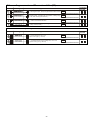
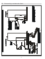
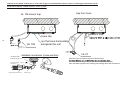
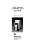
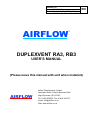
Version: 02
Issue: 30.11.2010
Code: R_12_V02_EN_VENT_2010_11
AIRFLOW
EN
™
DUPLEXVENT RA3, RB3
USER’S MANUAL
(Please leave this manual with unit when installed)
AIRFLOW
™
Airflow Developments Limited
Lancaster Road, Cressex Business Park
High Wycombe, HP12 3QP.
Tel: 01494 525252. Fax: 01494 461073
e-mail: [email protected]
Web: www.airflow.co.uk
I M P O R TA N T N O T I C E S :
•
•
•
•
•
•
•
•
•
•
•
•
•
•
•
•
•
•
Heat recovery DUPLEXVENT ventilation units are intended for comfort ventilation in a basic environment with
relative humidity up to 90%. Should the appliance be used for other purposes or not operated properly in
compliance with instructions specified in the User’s Manual, the manufacturer has no liability for resulting damage.
The appliance may only be operated by adults who have made themselves familiar with the User’s Manual.“
The user must not tamper with or modify any part of the appliance, particularly its electrical wiring!!
Only professional service technicians with relevant qualifications may perform equipment repairs. Unprofessional
repairs are very risky and may result in a loss of warranty.
Before opening the door of the appliance for cleaning, filter replacement or general maintenance, always make sure
that it is disconnected from power supply and cannot be re-connected by another person.
To prevent injury caused by the fan wheel, ductwork at least 2 metres long must always be connected to the fan
discharge side. The ductwork must be fastened in such a way so that it cannot be removed without using tools.
The appliance may only be installed in areas with temperatures above 15°C with relative humidity 60% at 20°C.
If the appliance has been out of operation for a long period of time, extra care must be taken during its recommissioning.
The appliance designed for a basic environment may be operated within the temperature range of ventilation air
between -25°C and 45°C and relative air humidity up to 90%, in an environment where there is no risk of fire or an
explosion of flammable gases and fumes containing organic solvents or aggressive substances that might damage
the mechanical parts of the unit. If there is a danger of such gases and fumes temporarily entering the duct (e.g.
floor bonding, painting), the appliance must be switched off sufficiently in advance.
Electrical installation, commissioning and adjustment of the appliance may only be carried out by persons with
appropriate electrotechnical qualifications.
Before installing the appliance and putting it into operation, carefully read the User’s Manual!!
The appliance and all accessories must be installed and used in compliance with the project, the manufacturer’s
technical conditions and applicable legal regulations and technical standards in effect.
The appliance may not be installed or operated in an aggressive environment that could adversely affect external
and internal mechanical components.
Before putting the appliance into permanent operation, an initial inspection report of the power supply for the
appliance must be provided.
In the event of a failure, the appliance must be disconnected from power supply as soon as possible!
During the handling and installation of the appliance comply with all principles of safe work (including the safety of
work at height and work with suspended loads) and use appropriate work and protective equipment.
During installation avoid damaging or deforming the appliance’s case.
An appliance fitted with a hot water air heater (optional accessory) must be permanently connected to power supply
to provide for the anti-freeze protection of the hot water air heater. In case of a prolonged power outage the heating
medium must be drained from the hot water air heater. We recommend draining the heating medium from the
heater by pressurized air instead of gravity flow!!
The manufacturer cannot be held liable for damages resulting from the unprofessional
installation of the appliance in disagreement with the installation manual and common
practices in installing HVAC units and control systems
2
Product label
1
Unit type and motor size
(DUPLEXVENT RA3 450/450)
(DUPLEXVENT RB3_EC 550/450)
2
3
4
5
6
7
8
9
10
Hot air heating and ventilation unit with heat
recovery
1
2
7
3
8
4
9
5
6
10
The appliance may only be repaired by a service
technician..
The appliance must be disconnected from power
supply using the main switch before cleaning or repair.
3
Maximum air re-circulation
Maximum air ventilation
Maximum power input
Weight of the hot air heating unit
Year of production
Heat recovery efficiency
Voltage
Heat exchanger type
Serial No.
Content
Content ................................................................................................................................................................................4
A)
General description .....................................................................................................................................................5
1.
Description of main parts.............................................................................................................................................5
B)
Installation ...................................................................................................................................................................7
1.
Installation of the unit ..................................................................................................................................................7
2.
Installation of CP 08 RD controller ..............................................................................................................................8
3.
Commissioning............................................................................................................................................................8
C)
Spare parts, repairs ............................................................................................................................................8
Functions.....................................................................................................................................................................8
1.
Basic functions ............................................................................................................................................................8
2.
Recirculation air heating .....................................................................................................................................8
Exhaust air extraction .........................................................................................................................................8
Mixing damper ....................................................................................................................................................9
Heat recovery exchanger....................................................................................................................................9
Automatic bypass damper ..................................................................................................................................9
Filtration..............................................................................................................................................................9
Controlling the operation of DUPLEXVENT R_3 units ................................................................................................9
3.
Problems and troubleshooting.....................................................................................................................................9
4.
Maintenance..............................................................................................................................................................10
Replacing filter cloth or filter cassettes .............................................................................................................10
a)
Recirculation filter - textile
10
b)
Recirculation filter - cassette
11
5.
c) Pre-filters (expanded metal mesh)
12
Cleaning the heat recovery exchanger .............................................................................................................12
General technical data ..............................................................................................................................................14
D)
Fitting DUPLEXVENT R_3 units ...............................................................................................................................15
E)
Operating modes of DUPLEXVENT R_3 units..........................................................................................................18
F)
Control system connection diagram ..........................................................................................................................20
G)
Connecting condensate drain....................................................................................................................................24
4
A)
General description
1.
Description of main parts
5
DUPLEXVENT RB3-EC UNIT
CP O8 RD CONTROLLER
Warm-air heating and ventilation
units for low-energy residential
buildings and passive homes
Rotary controller
Operation
status
display
Integrated
temperature
sensor
Figure -Basic DUPLEXVENT RB3-EC unit
Light-current cable line
Low-speed
recirculating
EC fan
Low-temperature
hot- water- air-heater
Optional evaporator
for mechanical cooling
(version RB3-EC-CHF)
or water-based cooling
(version RB3-EC-CHW)
Circular
connecting
ports (5)
Connecting
terminal
board control
module
Re-circulation and
supply air filter (G4,F7)
Mixing and
shut-off
damper with
servo drive
under a cover
Exhaust air EC fan
Expanded metal
mesh pre-filter e1
Expanded metal
mesh pre-filter i1
Counter-flow heat
recovery exchanger
with efficiency up to 90%
Figure – Modified DUPLEXVENT RB3-EC-CHW
(with a water-based cooler)
Integrated
double bypass damper with
servo drive (closes the heat recovery
exchanger when the bypass opens)
6
B)
Installation
1.
Installation of the unit
The fitting of DUPLEXVENT R_3 hot air units is described in Appendix D.
DUPLEXVENT RA3 units:
A minimum required installation space, including HVAC duct connections and access for operating the unit:
● window version ...................................................................
1,65x1,2x2,4 m
Minimum distances from building structures:
● in front of the unit................................................................
0,9 m (*0,6 m)
● from the sides .....................................................................
0,1 m
DUPLEXVENT RB3 units:
A minimum space required for installation including HVAC ducts and access for operators:
● ceiling-mounted version - installation space .....................
1.2 x 1.5 x 2.45 m
- operation space.......................
1.2 x 1 m
Minimum distances from building structures:
● from sides with no outlet ports............................................
● from sides with outlet ports.................................................
0.1 m
0.3 m
Note: * the size of the utility room and minimum distances from building structures in front of the unit with a removable
door without hinges.
For more detailed descriptions of installation of the units see the following documents:
HVAC INSTALLATION
RECOMMENDED INSTALLATION DETAILS FOR HOT AIR HEATING
AND VENTILATION SYSTEMS
For a detailed description of connecting to a CH (heating section) system see the following document:
:
CH
GENERAL DIAGRAMS OF CONNECTING
VARIOUS HEATING
SOURCES TO DUPLEXVENT
RA3 HOT AIR UNITS
For the details of connecting a control system with DUPLEXVENT R_3
units see Appendix F.
For connecting condensate drain see Appendix G.
For more details on connecting condensate drain from the unit
see the following document:
CONNECTING CONDENSATE DRAIN
RECOMMENDED INSTALLATION DETAILS
7
sewer
inleti
CONDENSATE DRAIN
CONNECTION
RECOMMENDED FITTING DETAILS
- details of connecting a condensate drain
from ventilation and warm- air HVAC units
DUPLEXVENT R_, DUPLEXVENT EC and
DUPLEX ECV series units to a sewer
system, including recommended use
2.
Installation of CP 08 RD controller
For a detailed description of installing and operating a CP08RD incl. recommended operation mode settings see the
following document:
CP-08 RD CONTROLLER
FOR DUPLEXVENT R_3 HVAC UNITS
The User’s Manual is supplied with the controller.
The controller is installed in a twin-box set in the wall of the building
3.
Commissioning
DUPLEXVENT R_3 units may only be put into operation by authorized service technician, who is required to fill out and
hand over a signed “COMMISSIONING REPORT”. A warranty for DUPLEXVENT R_3 units is provided on the basis of
that report.
Spare parts, repairs
We recommend commissioning all repairs of the controllers, within or after their warranty period, to a professional
servicing firm or trained service technician. Please contact the manufacturer for details regarding the nearest service
point.
C)
Functions
For the operation modes of DUPLEXVENT R_3 hot air units see Appendix E.
1.
Basic functions
Recirculation air heating
Recirculation air is filtered inside the unit, heated in the hot water heat recovery exchanger and transported by means of
a low-speed fan into the various diffusers in the rooms.
The integrated heating facility turns on when all the following conditions are met:
1) The unit is ON (medium or maximum performance level)
2) It is set to Heating Season (HS)
3) The room thermostat is ON - a request for heating from the CP 08 RD controller
4) Temperature behind the heater is lower than the maximum temperature set on the control module board
(trimmer P1).
Heating itself starts depending on a heating source installed (a boiler, an auxiliary pump etc. are turned on).
Exhaust air extraction
It is intended for independent extraction from the toilet, bathroom and kitchen, i.e. areas where recirculation is not
allowed. Extraction can be set manually (mode 1 or 2) or it starts automatically after lights in the toilet or bathroom are
turned on or a command comes from the kitchen, regardless of the manual setting of the controller. Various options
differ depending on the installation location - for information please contact the installation firm.
Starting with start-up delay and run-down times
To start extraction from the bathroom and toilet inputs D1, D2 and D3 with delay start-up and run-down times. These
start-up delay and run-down times can be set within a range - 0-5 minutes for start-up (1 minute by default) and 1-10 for
8
shut-down (5 minutes by default). The setting can only be made by a person authorized by supplier - a service
technician.
The ventilation run-down time is automatically reduced depending on outside temperature - the lower the outside
temperature, the shorter the run-down time.
Immediate start-up without run-down
This option is used for starting via an external phase signal from the kitchen (input D4) or a room hygrostat (input D11).
Mixing damper
The unit’s mixing damper is used to set the ratio between fresh ventilation and recirculation air. When the unit is turned
off or the antifreeze protection facility is activated, it is shut down completely. It is controlled automatically following set
modes 1 to 5. If the unit is continuously operated in recirculation mode 3, short-time ventilation starts at pre-set intervals
to exchange air (a periodic ventilation start-up function).
Heat recovery exchanger
For more information on heat recovery exchangers see the technical data sheet of each unit.
Automatic bypass damper
The damper’s function is to bypass supply air outside the heat recovery exchanger.
Filtration
The unit has a G4 class textile filter fitted on the supply side as a standard. Optionally a F7 class filter can be installed.
Rough filters from expanded metal mesh are used for pre-filters.
2.
Controlling the operation of DUPLEXVENT R_3 units
An RM module and an outside temperature sensor are integral parts of your HVAC unit. The system these components
the system cannot be operated.
1. Control via a CP 08 RD controller - see the following document:
CP-08 RD CONTROLLER
User’s Manual
FOR DUPLEXVENT R_3 HVAC UNITS
(supplied with the controller)
2. Control via a higher-ranking system:
- for detailed documentation contact the manufacturer
3. External inputs:
- external signals (switches in the bathroom, kitchen, toilet)
- CO2 sensors
- A stop contact - when it is closed, the unit disables ventilation and only recirculation (and
heating) are enabled
See the following document:
CONSTRUCTION READINESS
ELECTRICAL INSTALLATIONS FOR DUPLEXVENT RA3 HOT AIR UNITS (with a CP08 RD controller)
3.
Problems and troubleshooting
Problem
Reduced ventilation
capacity
Condensate builds up
inside the unit
Insufficient heating
Possible causes
Clogged air filters
Clogged suction lamellas or
dented air duct
Blocked condensate drain line
A siphon is not installed or it is
not big enough
The unit is not fitted horizontally
Air locked heat exchanger
Troubleshooting
Check filters and replace if necessary
Check air supply ducts and clean if necessary
Check the line, clean or replace if necessary
The siphon must correspond with the picture in
Chapter G
Adjust the position of the unit so that it is
horizontal or sloping (depending on the location
and type of the unit)
Bleed
9
Problem
capacity of the heater
Possible causes
Thermostat fails to start
Heat source fails to start
Different volumes of
fresh and exhaust air
Incorrect damper setting
Incorrect fan speed setting
After connecting the
controller and power
supply the unit fails to
react
No voltage in the unit
Incorrectly connected
conductors
Interrupted line
The unit was connected to
power supply before the CP 08
RD controller was installed
4.
Troubleshooting
Inspect - we recommend using a professional
service company
Inspect - we recommend using a professional
service company
Adjust - we recommend using a professional
service company
Adjust - we recommend using a professional
service company
Inspect the upstream circuit breaker and fuse
disconnector. Contact a specialized electrical
installation company.
Check again whether all conductors have been
properly connected.
Check for the tightness of conductors in
terminals (assign to service technician).
Check whether the line was not damaged (slit,
broken etc.) when it was fitted to connect the
ventilation unit and controller (assign to service
technician).
Disconnect the unit from power supply, wait for 5
seconds and re-connect.
Maintenance
Replacing filter cloth or filter cassettes
(the following procedure applies to DUPLEXVENT RK2 and RA3 units; filters in other units have different shapes and
filters in DUPLEXVENT R_3 units are fixed in a different way)
a) Recirculation filter - textile
1 Disconnect the hot air unit from power supply by switching off the upstream circuit breaker.
2 Open the door.
3 Slide out the filter and replace the G4 (F7) cloth. Make sure the filter is positioned so that air comes in through the
blue side of the filter and comes out through the white one (the white side faces the fan). An F7 filter must be
positioned so that air enters through the “hairy” side. Slide the filter back in. Filters in DUPLEXVENT R_3 units
should be replaced after approx. 10-12 weeks of operation. The replacement interval is shown on the CP08RD
controller.
1
2
3
4
10
4 Close the door. Re-connect the hot air unit to power supply by switching on the circuit breaker.
b) Recirculation filter - cassette
1 Disconnect the hot air unit from power supply by switching off the upstream circuit breaker.
2 Open the door.
3 Slide out the G4 (F7) cassette filter. The direction of air passage through the filter is indicated on the filter by an
arrow. Filters in DUPLEXVENT R_3 units should be replaced after approx. 10-12 weeks of operation. The
replacement interval is shown on the CP08RD controller.
1
2
3
4 Close the door. Re-connect the hot air unit to power supply by switching on the circuit breaker.
11
c) Pre-filters (expanded metal mesh)
1 Disconnect the hot air unit from power supply by switching off the upstream circuit breaker.
2 Open the door.
3 Slide out the filter, wash it with warm water (max. 60-70°C) with detergent and let it dry (can be cl eaned in a
dishwasher). Slide back in Slide out the filter, wash it with warm water (max. 60-70°C) with detergent and let it dry
(can be cleaned in a dishwasher). Slide back in.
2
1
4 Close the door. Re-connect the hot air unit to power supply by switching on the circuit breaker.
Cleaning the heat recovery exchanger
Provided that proper maintenance and filter cassette replacement are carried out, the heat recovery exchanger does
not have to be cleaned very often. Clean only when heat-exchange surfaces have been stained. Cleaning should be
done approximately once every 4-5 years of operation.
Cleaning the heat recovery exchanger of DUPLEXVENT RA3 hot air units
1 Disconnect the hot air unit from power supply by switching off the upstream circuit breaker.
2 Open the door.
2
1
3
12
3 Slide the heat recovery exchanger out along the guide rails.
4
5
4 Clean the heat recovery block by warm water (max. 60-70°C) with detergent and let it dry.
5 Fit the heat recovery exchanger back in the same position. Install the cover
Cleaning the heat recovery exchanger of DUPLEXVENT RB3 warm air units
1 Disconnect the warm air unit from power supply by switching off the upstream circuit breaker.
2 Open the door.
3 Loosen the clips that hold the exchanger cover in place and remove it (hold with your hand, otherwise the cover
might fall down due to its overhead position!!!)
1
2
4 Slide the heat recovery exchanger out along the guide rails (hold with your hand – overhead handling!!!).
3
5 Clean the heat recovery block by warm water (max. 60-70°C) with detergent and let it dry.
6 Fit the heat recovery exchanger back in the same position, fit the cover and secure
13
5.
General technical data
The general technical data of DUPLEXVENT R_3 units are specified in the appendix.
Other detailed technical data of DUPLEXVENT R_3 units and the CP08RD controller are shown in technical data
sheets and accompanying documents (Installation details etc.).
14
D)
Fitting DUPLEXVENT R_3 units
DUPLEXVENT RA3
15
DUPLEXVENT RB3 – fitting the unit
ceiling-mounted unit
ceiling
(side without
.
Attachment to the building structure to be designed according
to the weight of the unit. Slope the unit toward the condensate
Leave a space of at least 5 mm between the unit and ceiling.
Minimum lateral distances: 100 mm from the side without ports,
300 mm from the side with ports.
Optional fixing of ceiling-mounted DUPLEXVENT RB3 units on to anti-vibration mountings
Detail D
threaded rod M12
minimum distance between the mounting and ceiling – 5 mm
rubber bushing (anti-vibration mounting)
e.g. Rubena GP 32x13.5/32
washer, e. g. R 13x30
2 x nut M12
16
u n it d o o r
R 3 1 5 0 11
R 3 1 5 0 1 2
(C H W , C H F )
D is ta n ce X : sid e a g a in st h in g e s X = 3 5 m m , h in g e a n d co n d e n sa te d ra in sid e X = 4 4 m m
T E X b o lts (m a x . le n g th 1 0 m m )
th e e d g e o f th e c a s e .
S lid e p la s te rb o a rd a b o v e th e c o lla r.
openable door
RB3
M in im u m d is ta n c e o f th e U D
p ro file fro m th e u n it is 1 5 0 m m .
( C H W,
CHF)
C o n d e n s a te
c o n d e n s a te
e a lo n g sid e
(m in . s lo p e 2 % )
ra w in g K 6 .
RB3
17
D e t.2
R u n th e
d ra in lin
th e u n it
a s p e r d
opening in the false ceiling
R B 3
R B 3
(C H W
C H F )
Ceiling-mounted DUPLEXVENT RB3: covering ceiling-mounted units
u n it d o o r
Fit a false ceiling at least 10 mm below the unit.
Cover the unit with an openable door
P U T T Y
(s ilic o n ,
a c ry lic p u tty )
(e.g. an inspection access door with,
D e ta il 2 : C o n n e c tin g
p la s te rb o a rd to th e u n it
u s in g s p a c e r p la te s
US lock, 12.5 mm thick)
e ta il 1 : C o n n e c tin g
la s te rb o a rd to th e u n it
ith o u t u s in g s p a c e r
la te s
Door size – see the dimensional drawing
Fit the door flush with plasterboard as per
D
p
w
p
the supplier´s documentation.
C e ilin g -m o u n te d D U P L E X V E N T R B 3 :
D e ta il o f fittin g a p la s te rb o a rd
fa ls e c e ilin g
E)
Operating modes of DUPLEXVENT R_3 units
DUPLEXVENT RA3
18
c2
i2
e1
i1
Balanced pressure ventilation mode
all year round
nc = 0 /h-1/
nv = 0,15 – 0,5 /h-1/
Balanced pressure ventilation with adjustable ventilation
3
capacity 75 to 450 m /h, with heat recovery or via a
bypass. It is designed for ventilation and additional
heating (without recirculation) in the transitional period.
Both fans are running, the mixing damper is shut down.
i2
e1
RB3–EC
DUPLEXVENT RB3
c2
i2
c1
e1
i1
Recirculation heating and ventilation mode
heating season
nv = 0,15 – 0,5 /h-1/
nc = 0,5 – 1,5 /h-1/
Hot air recirculation heating and balanced pressure
ventilation with the recovery of exhaust heat, with
3
recirculation capacity up to 500 m /h (at 150 Pa) and
3
ventilation capacity up to 450 m /h.
Both fans are running, the mixing damper is mixing
outside and recirculation air.
i2
e1
RB3–EC
utility
utility
i2
e1
i1
c2
i2
e1
i1
c2
c1
toilet
c2
hall
c1
hall
living space
room
c2
living space
room
Recirculation heating mode with intermittent ventilation
heating season
nv = 0
nc = 0,5 – 1,5 /h-1/
Overpressure ventilation mode
summertime
-1
-1
nv = 0,5 – 2,0 /h /
nc = 0 /h /
Intensive summertime ventilation of living spaces by a full
supply of outside air or through a ground heat
exchanger. This mode can also be used for cooling at
night. Air is taken out via partially open windows. The
exhaust air fan is started by an impulse, the mixing
damper is in position “2”, the bypass damper is open.
Recirculation cooling mode with a ground heat
exchanger (GHE-c, GHE-s)
summertime
nv = 0 /h-1/
nc = 0,5 – 1,5 /h-1/
Intensive summertime circulation cooling of living
spaces by indoor air recirculating through a ground
heat exchanger. The exhaust air fan is started by
an impulse, the mixing damper is in position “2”,
and the bypass damper is open. It can only be used
in conjunction with a ground air heat exchanger or
using antifreeze fluid.
RB3–EC
The basic recommended operation mode of recirculation heating.
When people are present, the extraction fan with adjustable run
down time is switched on and off by an impulse from the toilet
and bathroom, or an impulse from the kitchen to mode 1 without
run down time. Ventilation can also be started periodically at set
interval, always with heat recovery. This mode is also used for
heating via an air-conditioning unit during the transitional period
when mechanical cooling is provided.
utility
i2
e1
RB3–EC
c2
i1
c1
toilet
hall
i1
utility
toilet
RB3–EC
c1
toilet
i1
utility
toilet
c2
living space
room
c2
hall
c1
hall
living space
room
c2
living space
room
Recirculation mechanical cooling mode
summertime
nc = 0,5 – 1,5 /h-1/
nv = 0 /h-1/
Intensive recirculation cooling of living spaces in conjunction
with an outdoor condensation unit (“mechanical cooling”).
When people are present, the ventilation fan with adjustable
run down time is switched on and off by an impulse from the
toilet and bathroom, or an impulse from the kitchen to mode
1 without run down time. In this case cooling is disabled.
Ventilation can also be started periodically at set intervals.
c1 ..... an inlet of recirculation air from living spaces to the unit
c2 ..... an outlet of heating, cooling and fresh air from the unit
to living spaces
RB3–EC
c2
i1
utility
c1
toilet
hall
c2
living space
room
e1 ..... a fresh outside air inlet
i1 ..... an inlet of exhaust air from sanitary facilities to the unit
i2 ..... an outlet of exhaust air from the unit
19
F)
Control system connection diagram
DUPLEXVENT RA3 - EC (also applies to other DUPLEXVENT R 3 series units an identical system of control)
An alternative method of connecting a standard control system (measurement & control) for DUPLEXVENT R_3 - EC
units:
(more alternative ways of connecting eternal devices and controls or sensors. From the controlling point of view some
inputs and outputs are optional and depending on the settings made by the service technician may be used for different
purposes - programmable settings. Some items are therefore shown more times in the connection diagram, during
installation, however, can only be used for a single specific function selection. The particular method of connection will
be specified by the designer or installation firm).
20
Basic DUPLEXVENT R_3 connections
Completed,
checked
Application
Cable type
Supply voltage 230V/50Hz
- recommended protection 4A, char. B
Controller
CP 08 RD
Room temperature
sensor ADS
100-ABB (optional)
Outside air temperature sensor
TE1-ADS110
Optional elements
Supply switch
(e.g. Kitchen)
Ground exchanger shut-off damper or facade fresh air
suction damper servo drive
-control voltage 24V, max. 0.5 A
(servo drive type e.g. LM 24A)
HVAC emergency shut down
-input for voltage-free opening contact
Analogue/contact input No. 1 – e.g. CO2, movement or
relative humidity sensor
(signal 0-10V, closing contact)
Analogue/contact input No. 2 – e.g. CO2, movement or
relative humidity sensor
(signal 0-10V, closing contact)
Low voltage output 24 V / max. 2W
(e.g. controlling kitchen extraction damper servo drive
LM 24A)
Zone ventilation damper servo drive – zone 1, control
voltage 24V, max. 0.5A
(servo drive type e.g. LM 24A)
Zone ventilation damper servo drive – zone 2, control
voltage 24V, max. 0.5A
(servo drive type e.g. LM 24A)
If the source is a boiler or IZT or an electric boiler
DUPLEXVENT R
Cable type
Application
Hot water source control
- closing contact (max. 230V/0.5A)
External thermostat
- input for voltage-free closing contact
21
Room name, No
Completed,
checked
If the source is a condensation boiler
DUPLEXVENT R
Application
Cable type
Room name, No
Completed,
checked
Room name, No
Completed,
checked
Hot water source control - closing contact
(max. 230V/0.5A)
Signal 0-10V output - condensation boiler
temperature control
If the source is an electric heater
DUPLEXVENT R
Cable type
Application
0-10V signal output
-switching on electric heater (e.g. EPO-V)
-impulse control
-connections made inside the unit
If the source is a controllable node
DUPLEXVENT R
Cable type
Application
Room name, No
Completed,
checked
Hot water source control-closing contact
(max. 230V/0.5A)
SK output, signal 0-10V - control node valve control
(e.g. servo drive LM24SR)
External thermostat
- input for voltage-free closing contact
If a HP is installed with back-up source TPV
DUPLEXVENT R
Cable type
Application
Room name, No
Completed,
checked
Room name, No
Completed,
checked
Hot water source control - closing contact
(max. 230V/0.5A)
External thermostat
- input for voltage-free closing contact
0-10V signal output
- heat pump performance level control
Closing output - switching HP over (closed = heating ON),
+12V, max. 30mA (open collector)
Heat pump output contact
- outdoor unit defrost indication
If the cooling source is an evaporator (Dir)
DUPLEXVENT R
Cable type
Application
Closing output - switching HP over (closed = heating ON),
+12V, max. 30mA (open collector)
22
If the cooling source is an HP or water chiller (TC)
DUPLEXVENT R
Cable type
Application
Room name, No
Completed,
checked
Room name, No
Completed,
checked
0-10V signal output - heat pump performance level control
Closing output - switching HP over (closed = heating ON),
+12V, max. 30mA (open collector)
Heat pump output contact
- outdoor unit defrost indication
Closing output - cooling request signal
(relay, max 8A, 230V)
A circulation GHE (GHEc) is installed
DUPLEXVENT R
Cable type
Application
GHEc damper servo drive fresh air inlet from facade
- control voltage 24V, max. 0.5A
(servo drive type e.g. LM 24A)
GHEc damper servo drive
- circulation damper-control voltage 24V, max. 0.5A
(servo drive type e.g. LM 24A)
23
G)
Connecting condensate drain
24
Recommended method of connecting a condensate drain line in ceiling-mounted units DUPLEXVENT RB3
trap from hose
HL 138 stench trap
make a trap,
hose clip
25
inlet into a
HL 138
run the hose horizontally
alongside the unit
inlet into a
sewage system
detailed connection (cross-section)
condensate drain
assembly on the unit
secure by clip after
connecting
Use hose clips to make a trap from flexible hose.
(we recommend using a HL-21 with a ball cap to stop stench
from the sewer system from entering the building when the trap dries out).
sleeve
outlet washing machine hose
HL 21
extension pipe
Recommended method of connecting a condensate drain line in ceiling-mounted units
DUPLEXVENT RB3-CHW; CHF;CHP
trap from hose
HL 138 stench trap
make a trap,
hose clip
26
inlet into a
HL 138
run the hose horizontally
alongside the unit
inlet into a
sewage system
inlet into a
sewage system
detailed connection (cross-section)
condensate drain
assembly on the unit
secure by clip after
connecting
Use hose clips to make a trap from flexible hose.
(we recommend using a HL-21 with a ball cap to stop stench
from the sewer system from entering the building when the trap dries out).
sleeve
outlet washing machine hose
HL 21
extension pipe