1
Yotta 3 SAS/SATA JBOD Enclosure
User Guide
Ver : 1.3
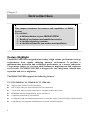
Preface
C
Cooppyyrriigghhtt 22001111
All rights Reserved- Printed in Taiwan
N
Noottiiccee
We make no warranties with respect to this documentation either express or
implied and provide it "as it". This includes but is not limited to any implied
warranties of merchantability and fitness for a particular purpose. The
information in this document is subject to change without notice. We assume no
responsibility for any errors that may appear in this document.
The manufacturer shall not be liable for any damage, or for the loss of
information resulting from the performance or use of the information contained
herein
T
Trraaddeem
maarrkkss
Product names used herein are for identification purposes only and may be the
trademarks of their respective companies. All trademarks or registered
trademarks are properties of their respective owners.
2
Hardware Operation Manual
R
Reegguullaattoorryy iinnffoorrm
maattiioonn
For Europe
This drive is in conformity with the EMC directive.
Federal Communications Commission (FCC) Statement
This equipment has been tested and found to comply with the limits for a Class
A digital device, pursuant to part 15 of the FCC Rules.
Those limits are designed to provide reasonable protection against harmful
interference in a residential installation. This equipment generates, uses and can
radiate radio frequency energy and, if not installed and used in accordance with
the instructions, may cause harmful interference to radio communications.
However, there is no guarantee that interference will not occur in a particular
installation. If this equipment does cause harmful interference to radio or
television reception, which can be determined by turning the equipment off and
on, the user is encouraged to try to correct the interference by one or more of
the following measures:
Reorient or relocate the receiving antennas.
Increase the separation between the equipment and receiver.
Connect the equipment into an outlet on a circlet different from that to which
the receiver is connected.
Consult the dealer or an experienced radio/TV technician for help.
Warning:
A shielded-type power cord is required in order to meet FCC emission limits
and also to prevent interference to the nearby radio and television reception. It
is essential that only the supplied power cord be used.
Use only shielded cables to connect I/O devices to this equipment.
You are cautioned that changes or modifications not expressly approved by the
party responsible for compliance could void your authority to operate the
equipment.
3
G
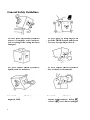
Geenneerraall SSaaffeettyy G
Guuiiddeelliinneess
DO NOT place the JBOD System on
uneven or unstable work surfaces.
Seek servicing if the casing has been
damaged.
DO NOT place or drop objects on
top of the JBOD System and do not
shove any foreign object into it.
DO NOT expose JBOD System to
liquids, rain, or moisture.
DO NOT expose JBOD System to
dirty or dusty environments.
DO NOT expose JBOD System to
magnetic field.
DO NOT expose JBOD System to
extreme temperatures ( below 5℃
or above 455℃) or to direct sunlight.
4
Hardware Operation Manual
About your User’s Guide
Welcome to your Hardware Installation Guide. This manual covers everything
you need to know in learning how to install your JBOD system. This manual
also assumes that you know the basic concepts of JBOD technology.
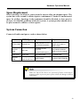
Guide to conventions
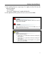
Important information that users should be aware of the following icons:
This icon indicates the existence of a potential hazard that could result
in personal injury, damage to your equipment or loss of data if the
safety instruction is not observed.
This icon indicates useful tips on getting the most from your JBOD
controller.
Important terms, commands and programs are put in Boldface font.
Screen text is given in screen font.
5
Table of Contents
PREFACE .................................................................................................2
COPYRIGHT 2011...................................................................................2
NOTICE ..................................................................................................2
TRADEMARKS ........................................................................................2
REGULATORY INFORMATION .................................................................3
GENERAL SAFETY GUIDELINES .............................................................4
T
TA
AB
BL
LE
EO
OF
FC
CO
ON
NT
TE
EN
NT
TS
S ............................................................6
CHAPTER 1 ..............................................................................................8
INTRODUCTION ..........................................................................8
FEATURE HIGHLIGHT.............................................................................8
BEFORE YOU BEGIN .............................................................................10
Unpacking & Checking The Equipment ........................................10
What else you need ........................................................................14
IDENTIFYING PARTS OF THE JBOD SYSTEM.........................................15
Front View .....................................................................................15
Rear View.......................................................................................20
SPACE REQUIREMENT ..........................................................................29
SYSTEM CONNECTION .........................................................................29
INSTALL HARD DISKS ...........................................................................30
CHAPTER 2 ............................................................................................32
H
HA
AR
RD
DW
WA
AR
RE
E IIN
NS
ST
TA
AL
LL
LA
AT
TIIO
ON
N .........................................32
REPLACE THE JBOD CONTROLLER .....................................................32
HOT SWAPPING TO REPLACE THE FAN MODULE ..................................35
HOT SWAPPING TO REPLACE THE POWER MODULE .............................39
INSTALL THE YOTTA 3 JBOD SYSTEM IN A RACK ...............................42
HOW TO DEPLOY THE SAS JBOD WITH YOTTA 3 SAS RAID...............46
TURNING ON FOR THE FIRST TIME ........................................................58
TURNING OFF .......................................................................................58
APPENDIX A ..........................................................................................59
SETUP CLI CONNECTION .....................................................................59
CLI COMMAND SET.............................................................................60
HELP - Show All CLI commands and its usage ............................60
Pass - Set Password.......................................................................62
LO - Logout CLI shell....................................................................62
LINK - Link rate Control ...............................................................62
TH - Operate the Thermal Attribute ..............................................63
SYS - Print System Information .....................................................64
BU - Operate the Buzzer Attribute.................................................66
FAN - Operate the Fan Attribute...................................................67
ST - Store System Setting ...............................................................68
6
Hardware Operation Manual
LSD – List Devices Status..............................................................68
RESET - System Software Reset.....................................................71
SHOWLOGS - Print System Log. ..................................................71
CLEARLOGS - Print System Log. .................................................72
FDL - File DownLoad ...................................................................72
APPENDIX B ..........................................................................................73
SAS JBOD FIRMWARE UPDATE PROCEDURE .......................................73
APPENDIX C ..........................................................................................76
S
SP
PE
EC
CIIF
FIIC
CA
AT
TIIO
ON
NS
S ......................................................................76
7
Chapter 1
Introduction
This chapter introduces the features and capabilities of JBOD
System.
You will find:
A
Affuullll iinnttrroodduuccttiioonn ttoo yyoouurr JJB
BO
OD
D SSY
YSST
TE
EM
M
D
e
t
a
i
l
s
o
f
k
e
y
f
e
a
t
u
r
e
s
a
n
d
s
u
p
p
l
i
e
d
a
c
c
e
s
s
Details of key features and supplied accessoorriieess
A
Acchheecckklliisstt ooff ppaacckkaaggee ccoonntteennttss
A
Acchheecckklliisstt ooff w
whhaatt eellssee yyoouu nneeeedd ttoo ssttaarrtt iinnssttaallllaattiioonn
FFeeaattuurree H
Hiigghhlliigghhtt
The JBOD SYSTEM is designed to meet today’s high volume, performance storage
requirements from rapidly changing business environment. It provides a
maximum data protection and exceptional performance in a storage subsystem.
Target usage ranges are set from small business to departmental and corporate
server needs. The JBOD SYSTEM is designed for easy integration, smooth data
expansion and server migration.
The JBOD SYSTEM supports the following features:
Y3-12/16/24S6JS6, Y3-12S6JS6-D, Y3-12S6AS6:
Supports SAS 6Gb/SATA 6Gb disk drives.
One 4x 6Gb wide-port SAS connectors for host connection.
Two 4x 6Gb wide-port SAS connectors for expander module daisy chain.
Redundant and Hot Swappable Fan, Power and Drives.
Completely monitored by In-band SES.
Configuration and environmental information is accessible either via the Serial Port or RAID System.
Load sharing, hot swappable redundant power system with PFC function.
8
Hardware Operation Manual
Y3-12/16/24S6TS6:
Dual SAS Expander
Supports SAS & NL SAS 6Gb disk drives.
Support SATA 6Gb disk drives with SAS Bridge Board (optional).
One 4x 6Gb wide-port SAS connectors for host connection. /per SAS Expander
Two 4x 6Gb wide-port SAS connectors for expander module daisy chain. /per SAS Expander
Redundant and Hot Swappable SAS Expander, Fan, Power and Drives.
Completely monitored by In-band SES.
Configuration and environmental information is accessible either via the Serial Port or RAID System.
Load sharing, hot swappable redundant power system with PFC function.
9
B
Beeffoorree yyoouu bbeeggiinn
Unpacking & Checking The Equipment
Before unpacking the JBOD SYSTEM, prepare a clean, stable surface to put the
contents of your JBOD SYSTEM shipping container. Altogether, you should find
the followihe package:
10
Hardware Operation Manual
SAS to SAS/SATA JBOD System (Rack-mount, SAS Expander x 1)
Y3-12S6JS6 :
12 Bay JBOD System x 1
JBOD system Hardware User Guide (CD media )
RS232 cable x 1
SFF-8088 Mini SAS to SFF-8088 Mini SAS Cable x 1
Power Cord x 2
HDD tray x 13
Mounting screws (bag) ×1
Y3-12S6AS6 :
12 Bay JBOD System x 1
JBOD system Hardware User Guide (CD media )
RS232 cable x 1
SFF-8088 Mini SAS to SFF-8088 Mini SAS Cable x 1
Power Cord x 2
FAN x 1
HDD tray x 13
Mounting screws (bag) ×1
Y3-16S6JS6 :
16 Bay JBOD System x 1
JBOD system Hardware User Guide (CD media )
RS232 cable x 1
SFF-8088 Mini SAS to SFF-8088 Mini SAS Cable x 1
Power Cord x 2
FAN x 1
HDD tray x 17
Mounting screws (bag) ×1
Y3-24S6JS6 :
24 Bay JBOD System x 1
JBOD system Hardware User Guide (CD media )
RS232 cable x 1
SFF-8088 Mini SAS to SFF-8088 Mini SAS Cable x 1
Power Cord x 3
FAN x 1
HDD tray x 25
Mounting screws (bag) ×1
11
SAS to SAS/SATA JBOD System (Tower, SAS Expander x 1)
Y3-12S6JS6-D :
12 Bay JBOD System x 1
JBOD system Hardware User Guide (CD media )
RS232 cable x 1
SFF-8088 Mini SAS to SFF-8088 Mini SAS Cable x 1
Power Cord x 2
HDD tray x 13
Mounting screws (bag) ×1
SAS to SAS/SATA JBOD System (Rack-mount, SAS Expander x 2)
Y3-12S6TS6:
12 Bay JBOD System x 1
JBOD system Hardware User Guide (CD media )
RS232 cable x 2
SFF-8088 Mini SAS to SFF-8088 Mini SAS Cable x 2
Power Cord x 2
HDD tray x 13
Mounting screws (bag) ×1
Y3-16S6TS6:
16 Bay JBOD System x 1
JBOD system Hardware User Guide (CD media )
RS232 cable x 2
SFF-8088 Mini SAS to SFF-8088 Mini SAS Cable x 2
Power Cord x 2
FAN x 1
HDD tray x 17
Mounting screws (bag) ×1
Y3-24S6TS6:
24 Bay JBOD System x 1
JBOD system Hardware User Guide (CD media )
RS232 cable x 2
SFF-8088 Mini SAS to SFF-8088 Mini SAS Cable x 2
12
Hardware Operation Manual
Power Cord x 3
FAN x 1
HDD tray x 25
Mounting screws (bag) ×1
13
What else you need
Hard disk drives (Different JBOD model requires different numbers of HDDs).
Host computer with SAS interface or Host RAID System with SAS interface
Static grounding strap or electrostatic discharge (ESD) safe work area
Dedicated terminal or PC with third party communication software that supports ANSI
terminal emulation (required for viewing Monitor Utility)
The hard drives in a JBOD system should match in size and speed. All
drives in any array should be identical models with the same firmware
version. JBOD system can use any size drive, however the smallest
drive will determine the size of the array.
JBOD system does not require the installation of different drivers for
use with different operating systems. JBOD system is independent and
transparent to the host operating system.
It is often recommended to install the hard drive with same brand,
model no., interface and capacity in this RAID subsystem.
Due to hard drives spin at different speed and it may lead to
compatible issue or performance decline. So we do not recommend
users to install SAS and SATA hard drive meantime in an enclosure.
14
Hardware Operation Manual
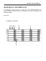
IIddeennttiiffyyiinngg PPaarrttss ooff tthhee JJB
BO
OD
D ssyysstteem
m
The illustrations below identify the various parts of the JBOD SYSTEM. Get
yourself familiar with these terms as it will help you when you read further in the
following sections:
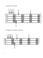
Front View
Y3-24S6JS6 / Y3-24S6TS6
15
Y3-16S6JS6 / Y3-16S6TS6
Y3-12S6JS6 / Y3-12S6TS6 / Y3-12S6AS6
16
Hardware Operation Manual
1.
Power On Indicator (Blue).
2.
Host System Access Indicator (Blue + blink).
3.
Power Fail Indicator (Red)
4.
Fan Fail Indicator (Yellow)
5.
Over Temperature Indicator (Yellow)
6. Cartridge Handle
7. Lock & Release-Button
8. HDD status LED Indicator
LED
?
Colors
Blue
Blue+ Blink
Indicate
HDD On Line
HDD Access
Red
HDD Error
17
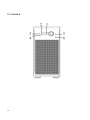
Y3-12S6JS6-D
18
Hardware Operation Manual
1. LCD Display Panel
The front panel LCD continuously displays the status of the JBOD system.
The following is an example of the JBOD system.
2.
Power On Indicator (Blue).
3.
Power Fail / FAN Fail / Over Temperature Indicator (Red)
4.
A
Host System Access Indicator (Blue + blink).
5. Function keys. (ENT, ESC, Scroll up, Scroll Down)
Keys
Up Arrow
Down Arrow
(ENT) Enter
(ESC) ESC
Descriptions
To scroll upward through the menu items
To scroll downward through the menu items
To confirm a selected item
To exit a sub-menu and return to previous
menu.
6. Power Switch
19
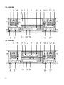
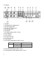
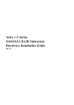
Rear View
Y3-24S6JS6
Y3-24S6TS6
20
Hardware Operation Manual
1. SAS CH 1/E (Expand out 2)
2. SAS CH 0 (Expand In)
3. SAS Expand Port (Expand out 1)
4. Terminal
5. Controller Box 1
6. Controller Box 2 (Reserved for SAS Expander 2)
7. FAN failure indicator (Rear / Front)
8. FAN Module 1
9. FAN Module 1 Latch
10. Power Switch
11. FAN failure indicator (Rear / Front)
12. FAN Module 2
13. FAN Module 2 Latch
14. AC inlet 1 & Latch
15. Power Module 1
16. AC inlet 2 & Latch
17. Power Module 2
18. AC inlet 3 & Latch
19. Power Module 3
20. SAS CH1/E LED Indicator (Link / Access)
LED
SAS
Colors
Green
Indicate
Link
Blue + Blink
Access
21. SAS CH0 LED Indicator (Link / Access)
22. SAS Expand Port LED Indicator (Link / Access)
21
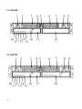
Y3-16S6JS6
Y3-16S6TS6
22
Hardware Operation Manual
1. SAS CH 1/E (Expand out 2)
2. SAS CH 0 (Expand In)
3. SAS Expand Port (Expand out 1)
4. Terminal
5. Controller Box 2 (Reserved for SAS Expander 2)
6. Controller Box 1
7. FAN failure indicator (Rear / Front)
8. FAN Module 1
9. FAN Module 1 Latch
10. Power Switch
11. FAN failure indicator (Rear / Front)
12. FAN Module 2
13. FAN Module 2 Latch
14. AC inlet 1 & Latch
15. Power Module 1
16. AC inlet 2 & Latch
17. Power Module 2
18. SAS CH1/E LED Indicator (Link / Access)
LED
SAS
Colors
Green
Blue + Blink
Indicate
Link
Access
19. SAS CH0 LED Indicator (Link / Access)
20. SAS Expand Port LED Indicator (Link / Access)
23
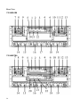
Y3-12S6JS6
Y3-12S6TS6
24
Hardware Operation Manual
1. Power Module 1
2. AC inlet 1 & Latch
3. FAN Module 1
4. FAN failure indicator (Rear / Front)
5. Power Switch
6. FAN Module 2
7. FAN failure indicator (Rear / Front)
8. Power Module 2
9. AC inlet 2 & Latch
10. SAS CH1/E LED Indicator (Link / Access)
LED
SAS
Colors
Green
Blue + Blink
Indicate
Link
Access
11. SAS CH 1/E (Expand out 2)
12. SAS CH 0 (Expand In)
13. SAS CH0 LED Indicator (Link / Access)
14. SAS Expand Port (Expand out 1)
15. SAS Expand Port LED Indicator (Link / Access)
16. Terminal
17. Controller Box 1
18. Controller Box 2 (Reserved for SAS Expander 2)
25
Y3-12S6AS6
1. Terminal
2. SAS Expand Port (Expand out 1)
3. SAS CH 0 (Expand In)
4. SAS CH 1/E (Expand out 2)
5. FAN Module Latch
6. FAN Module
7. FAN failure indicator (Rear / Front)
8. Power Module 2
9. Power Module 1
10. AC inlet 2 & Latch
11. AC inlet 1 & Latch
12. Power Switch
13. SAS CH1/E LED Indicator (Link / Access)
LED
SAS
Colors
Green
Blue + Blink
Indicate
Link
Access
14. SAS CH0 LED Indicator (Link / Access)
15. SAS Expand Port LED Indicator (Link / Access)
26
Hardware Operation Manual
Y3-12S6JS6-D
1. FAN Module
2. FAN failure indicator
3. AC inlet 1
4. Power Module 1
5. Terminal
6. SAS Expand Port (Expand out 1)
7. SAS Expand Port LED Indicator (Link / Access)
LED
SAS
Colors
Green
Blue + Blink
Indicate
Link
Access
27
8. SAS CH 0 (Expand In)
9. SAS CH0 LED Indicator (Link / Access)
10. SAS CH 1/E (Expand out 2)
11. SAS CH1/E LED Indicator (Link / Access)
12. AC inlet 2
13. Power Module 2
14. HDD status LED Indicator
LED
?
28
Colors
Blue
Blue+ Blink
Indicate
HDD On Line
HDD Access
Red
HDD Error
Hardware Operation Manual
SSppaaccee R
Reeqquuiirreem
meenntt
When selecting a location for your system, be sure to allow an adequate space. The
system has vents around it which requires a minimum of 3 inches of unobstructed
space for airflow. Openings in the equipment should be blocked, or there may be
an issue of reliability problems with your system. A system product should never
be place around a radiator or heat register.
SSyysstteem
mC
Coonnnneeccttiioonn
Connect all cables and power cord as shown below:
Cable
JBOD System Device
RS-232 Cable Terminal Port
Mini SAS
Cable
SAS CH0
Power Cord
Power inlet
Mini SAS
Cable
SAS Expander Port
ANSI Terminal or a PC
with Terminal emulator.
Debug port, to check and
monitor all of status of
JBOD system.
SAS HBA of Host
computer
Host interface between
Or SAS RAID System
/ SAS CH1/E Port
Purpose
JBOD and Host computer
A/C power outlet
A/C power input
JBOD System
Connect to SAS Expander
Make sure that all the devices are powered off before connecting or
removing cables to prevent power spikes which can damage technical
components.
29
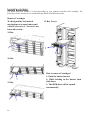
IInnssttaallll hhaarrdd ddiisskkss
The JBOD SYSTEM includes 12/16/24 (depending on your models) removable disk cartridges. The
following sections describe how to install disks into JBOD SYSTEM subsystems.
Remove Cartridges
We designed the lock/unlock
mechanism on a same button and
called EzSecurLock . No need a key
but with security .
24 Bay
12 Bay Tower
16 Bay
12 Bay
30
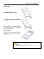
How to remove Cartridges?
1: Push the button inward
2: While holding in the button, then
slide down
3: The HDD door will be opened
automatically.
Hardware Operation Manual
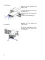
Install HDDs.
1) Put HDD into the Cartridge.
2) Align 4 screws holes on both HDD &
Cartridge.
3) Fasten all 4 screws to mount HDD in
the cartridge and make sure the HDD
is properly tightened.
Install Cartridges
Reversed the procedures of “Remove
cartridges” to install cartridges back
to JBOD system.
When using Redundant Controller, it is required to install SAS &
NL SAS HDDs.
31
Chapter 2
Hardware Installation
This chapter presents:
IInnssttrruuccttiioonnss iinn rreeppllaacciinngg ccoom
mppoonneennttss
I
n
s
t
r
u
c
t
i
o
n
s
i
n
r
e
p
l
a
c
i
n
g
t
h
e
Instructions in replacing the hhoott ssw
waappppaabbllee ccoom
mppoonneennttss
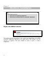
R
Reeppllaaccee tthhee JJB
BO
OD
DC
Coonnttrroolllleerr
Read the replacing notices in this chapter before proceeding with
replacement.
This section provides instructions for the removal and installation of the JBOD
controller components indicated in the figure below. This section is for the
reference of engineers. End users should not need to replace or remove
components.
32
Hardware Operation Manual
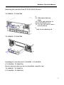
Removing the controller from Y3-12/Y3-16/Y3-24 series
Y3-24S6JS6 / Y3-24S6TS6
1:
1-1.) Disconnect the host
cables
1-2.) Turn anti-clockwise to
release the thumb screw.
1-3.) Use the eject kit to remove
controller board.
2:
Slide it back and lifting off
Y3-16S6JS6 / Y3-16S6TS6
Installing the controller into Y3-16S6JS6 / Y3-16S6TS6
(Y3-24S6JS6 / Y3-24S6TS6)
Reverse the procedures as above to install the controller into
Y3-16S6JS6 / Y3-16S6TS6
(Y3-24S6JS6 / Y3-24S6TS6).
33
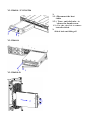
Y3-12S6JS6 / Y3-12S6TS6
1:
1-1.) Disconnect the host
cables
1-2.) Turn anti-clockwise to
release the thumb screw.
1-3.) Use the eject kit to remove
controller board.
2:
Slide it back and lifting off
Y3-12S6AS6
Y3-12S6JS6-D
34
Hardware Operation Manual
Installing the controller into
Y3-12S6JS6 / Y3-12S6TS6 / Y3-12S6JS6-D / Y3-12S6AS6
Reverse the procedures as above to install the controller into
Y3-12S6JS6 / Y3-12S6TS6 / Y3-12S6JS6-D / Y3-12S6AS6
H
Hoott SSw
waappppiinngg ttoo rreeppllaaccee tthhee FFaann M
Moodduullee
This section provides instructions for the removal and installation of the Fan
Module indicated in the figure below.
Y3-16S6 & Y3-24S6
Removing the Fan Module from
JBOD system
Remove the Fan modules by
pushing the latch to release the
lock of module then slide it back
and lifting off.
Installing the Fan module into
JBOD system :
Insert a Fan module into system,
the latch will lock the Fan module
automatically.
35
Y3-12S6 Series
Removing the Fan Module from
JBOD system
1.) Turn anti-clockwise to release
the thumb screw.
2.) Use the eject kit to remove Fan
Module.
3.) Slide it back and lifting off
Y3-12S6AS6
Installing the Fan module into
JBOD system :
Reverse the procedures as above
to install the Fan Module into
Y3-12S6 Series
36
Hardware Operation Manual
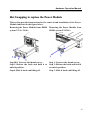
Y3-12S6JS6-D Tower series
Removing the Fan Module from
Y3-12S6 Tower series:
Installing the Fan module into
Y3-12S6 Tower series:
1.) Turn anti-clockwise to release
the thumb screw.
2.) Use the eject kit to remove Fan
Module.
3.) Slide it back and lifting off
Reverse the procedures as above to
install the Fan module into Y3-12S6
Tower series
37
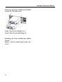
Replacing Fan in a Fan Module:
Step 1: Turn anti-clock wise to release the thumb screw.
Step 2: slide the cover to blue arrow direction .
Step 3: Remove the cover of Fan module and lift the Fans.
38
Hardware Operation Manual
H
Hoott SSw
waappppiinngg ttoo rreeppllaaccee tthhee PPoow
weerr M
Moodduullee
This section provides instructions for the removal and installation of the Power
Module indicated in the figure below.
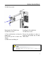
Removing the Power Module from JBOD Removing the Power Module from
system Y3-16 / 24S6 :
JBOD system Y3-12S6 :
Step1&2: Unscrew the thumb screw.
Step3: Release the latch and hold it at
unlock-position.
Step4: Slide it back and lifting off.
Step 1: Unscrew the thumb screw.
Step 2: Release the latch and hold it
at unlock-position.
Step 3: Slide it back and lifting off.
39
Hardware Operation Manual
Removing the Power Module from RAID
system Y3-12S6AS6 Series :
Step1: Unscrew the thumb screw.
Step 2: Slide it back and lifting off.
Installing the Power module into JBOD
system :
Insert a Power module then fasten the
screw.
40
Hardware Operation Manual
Y3-12S6 Tower series
Removing the Fan Module from
Y3-12S6 Tower series:
Installing the Fan module into
Y3-12S6 Tower series:
1.) Turn anti-clockwise to release the
thumb screw.
2.) Use the eject kit to remove Fan
Module.
3.) Slide it back and lifting off
Reverse the procedures as above to
install the Fan module into Y3-12S6
Tower series
The Power indicator will turn bright “Green” to indicate it has
powered on
41
Hardware Operation Manual
IInnssttaallll tthhee Y
Yoottttaa 33 JJB
BO
OD
D SSyysstteem
m iinn aa R
Raacckk
You are shipped with one rack mounting kit for each Yotta 3 JBOD system that
you intend to rack mount. Yotta 3 JBOD system is designed for installation into an
industry-standard 19-inch rack mount cabinet. Following the use of this section
for installing the Yotta 3 JBOD system into a Rack
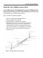
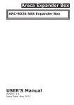
Step1: Assemble and adjust the slide Rails
a. Insert rear slide rail into left (right) slide rail
b. Adjust the length of the slide rails
c. Install P4*8M Screw and M4 NUT as figure 1
d. Determine where in the rack, the subsystem is going to be.
Install the brackets in the rack. Secure each side of the
brackets with two position screws through the front rack
posts, and two position screws through the rear rack posts.
When the rails can be properly fitted to the rack posts,
Fasten the screws.
Figure 1: Assembly Slid rail and rack posts
42
Hardware Operation Manual
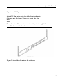
Step 2 : Install Clip nuts
Attach M5 clip nut on each side of the front rack posts.
Clip nuts use the figure 2 below to locate the clip
nuts.
Note:
These clip nuts will be used to secure the subsystem through its front ears
as will be discussed in Step 4.
Figure 2: Attach the clip nuts to the rack posts
43
Hardware Operation Manual
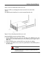
Step 3 : Slide the subsystem into the server rack
Lift the subsystem enclosure and slide it slowly and gently along the slide rail into
the rack.
Figure 3: Slide the subsystem into the server rack
44
Hardware Operation Manual
Step 4 : Secure the subsystem in the server rack
Fasten two M5 screws through the chassis ears in the front side of the
chassis.
The JBOD system should now be securely mounted into the rack.
Figure 4: Secure the subsystem in the server rack
Install the JBOD system into the Rack Cabinet
1. Lift the JBOD system (one person on each side of the JBOD System) and
approach the rack with the button-back of the JBOD system facing the end of
Slide rails.
2. Slide the JBOD system evenly and all the way into the rack cabinet.
3. Using the rack mount screws, secure the top and bottom of the JBOD system to
the rack frame.
Caution
The JBOD system is heavy; two people are required to move the
system in the procedure.
45
Hardware Operation Manual
H
Hoow
w ttoo ddeeppllooyy tthhee SSA
ASS JJB
BO
OD
Dw
wiitthh Y
Yoottttaa 33 SSA
ASS R
Raaiidd
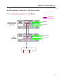
There are many topologies of SAS JBOD with Yotta 3 SAS Raid. Ways
to implement are as below:
Single Controller Unit (Rack-mount):
One SAS Raid subsystem with one SAS JBOD
46
Hardware Operation Manual
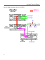
One SAS Raid subsystem with two SAS JBOD
IN
OUT
OUT
One SAS Raid subsystem with three SAS JBOD
IN
OUT
OUT
47
Hardware Operation Manual
One SAS Raid subsystem with four SAS JBOD
IN
OUT
OUT
48
Hardware Operation Manual
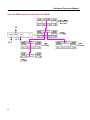
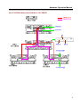
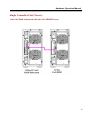
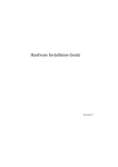
Dual Redundant Controller Unit (Rack-mount)
One SAS Raid subsystem with one SAS JBOD
JBOD Link A
JBOD Link B
Controller 1
24 Bay SAS-SAS
RAID Subsystem
(Rear Side)
Controller 2
SAS Expander 1
24 Bay
SAS JBOD
SAS Expander 2
IN
OUT
OUT
49
Hardware Operation Manual
One SAS Raid subsystem with two SAS JBOD
50
Hardware Operation Manual
One SAS Raid subsystem with three SAS JBOD
51
Hardware Operation Manual
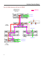
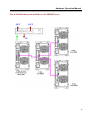
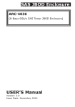
One SAS Raid subsystem with four SAS JBOD
24 Bay SAS-SAS
RAID Subsystem
(Rear Side)
JBOD Link A
JBOD Link B
Controller 1
Controller 2
IN
24 Bay
SAS JBOD
OUT
SAS Expander 1
24 Bay
SAS JBOD
24 Bay
SAS JBOD
SAS Expander 2
SAS Expander 1
16 Bay
SAS JBOD
52
SAS Expander 2
OUT
Hardware Operation Manual
Single Controller Unit (Tower):
One SAS Raid subsystem with one SAS JBOD(Tower)
53
Hardware Operation Manual
One SAS Raid subsystem with two SAS JBOD(Tower)
OUT
OUT
IN
54
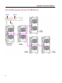
Hardware Operation Manual
One SAS Raid subsystem with three SAS JBOD(Tower)
OUT
OUT
IN
55
Hardware Operation Manual
One SAS Raid subsystem with four SAS JBOD(Tower)
OUT
OUT
IN
56
Hardware Operation Manual
It supports up to four tiers and 122 SAS/SATAII peripheral devices (SAS/SATA
HDDs + Raid Enclosures) by using SAS expanders.
One Volume Set supports up to 32 HDDs
One SAS Raid subsystem supports up to 128 Volumes
One SAS Raid subsystem supports up to 122 SAS/SATAII peripheral devices
(SAS/SATA HDDs + Raid Enclosures) by using SAS expanders.
There are four tiers within JBOD topology as above:
First tier is a RAID System.
Second tier is a SAS JBOD with a SAS CH0 on it. Connecting SAS CH0 to SAS
exp. Port on RAID System via a Mini SAS to Mini SAS Cable.
Third tier could be two SAS JBODs with a SAS CH0 port individually. One is
connected to the SAS EXP. Port on the second tier SAS JBOD via a Mini SAS to
Mini SAS Cable. Another is connected to the SAS CH1/E Port on the second tier
SAS JBOD.
Fourth tier is a SAS JBOD with a SAS CH0 on it. Connecting SAS CH0 to SAS
exp. Port on third tier SAS JBOD via a Mini SAS to Mini SAS Cable.
It is often recommended to install the hard drive with
same brand, model no., interface and capacity in this
RAID subsystem.
Due to hard drives spin at different speed and it may lead
to compatible issue or performance decline. So we do not
recommend users to install SAS and SATA hard drive
meantime in an enclosure.
57
Hardware Operation Manual
RAID members need to be included at the same enclosure
which means you need to create array in the same
enclosure. If RAID members are created from two or
more different enclosures, there would be some risks
(for example: if a mini-SAS cable gets problem, more
RAID members will be lost, volume sets belong to this
Array may be failed. Shutdown RAID and JBOD to fix
problem, after that, turn on JBOD and RAID system
again and controller will get array back, but in some
case it may not get the array back)
T
Tuurrnniinngg oonn ffoorr tthhee ffiirrsstt ttiim
mee
When cabling is completed, SAS RAID system + SAS JBOD system can be
turned on. This should be done in the following order:
1. First turn on the power switch of “SAS JBOD” system.
2. Then turn on the power switch of “SAS RAID” system
3. Power on and boot the host computer(s)
T
Tuurrnniinngg ooffff
When turning off SAS RAID system + SAS JBOD system, users are advised to
first shut down the server, then power off SAS RAID SYSTEM ,finally power
off SAS JBOD SYSTEM.
58
Hardware Operation Manual
Appendix A
SSeettuupp C
CL
LII ccoonnnneeccttiioonn
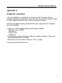
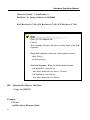
The SAS JBOD has a Command Line Interface (CLI) to manage all of its
functions, including customization. Access the CLI via your PC’s terminal VT100
or ANSI emulation program, such as Microsoft HyperTerminal.
With the SAS JBOD running and the RS-232 cable connected to the Terminal
port on SAS JBOD
1. Open any UART communication tools like Hype Terminal
• Bits per second: 115200
• Data bits: 8
• Parity: None
• Stop bits: 1
2. press any key on HyperTerminal window, the window will show " Password:"
prompt (Default Password: 0000)
3. Enter Password, the window will show "CLI>" prompt
4. Type help will show help screen.
59
Hardware Operation Manual
C
CL
LII C
Coom
mm
maanndd SSeett
The CLI has the following set of commands:
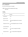
HELP - Show All CLI commands and its usage
Usage: help
Example:
CLI>help
============================================================
Test
Command
============================================================
Set Password
pass
logout CLI shell
lo
Link rate Control
link Index(D) High-Rate(D) Low-Rate(D)
link
Temperature Control
th Index(D) High-Warn(D) Low-Warn(D)
th
System Information
sys
Alarm Control
bu {mute | [warning(D) critical(D)]}
Bu
Fan Speed Control
60
fan LowestSpeed(D) WarningSpeed(D)
fan
Hardware Operation Manual
Drive Spin Up Control
spin Delay(D)[ms] Num(D)
spin
Store System Setting
st
List Devices Status
lsd [hdd | temp | volt | pwr | con | ..]
Resets the expander
reset watchdog(optional)
Route Table Read
rtr Display[ (Default)/d/z/dz]
Default display enabled entries with a
nonzero SAS address
d include disabled entries
z include entries with a zero SAS address
dz display all entries
Show the current logs
showlogs DisplayMode(hex, detail, default)
Clear the logs
clearlogs
Add string to the log
log "string"
File Download
fdl { code | mfgb |..} Buffer-Offset(H)
Erase[ Y(Default)/ N ]
Display Info for all phys
phyinfo Help[ ? ]
Display/Reset all phy counters counters reset(optional)
61
Hardware Operation Manual
Display expander SAS address sasaddr
CLI Help
help command
============================================================
Pass - Set Password
Usage: pass (Max. 8 chars, Min. 4 chars)
Example:
CLI>pass
Old Password:****
New Password:****
verify new Password:****
Update Successfully But Not Save Permanently!
LO - Logout CLI shell
Usage: lo
Example:
CLI>lo
Password:
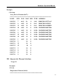
LINK - Link rate Control
Usage: link
62
Hardware Operation Manual
Example:
CLI>link
Array Device Element (0x17):
===================================================
NAME
PHY NLR MAX MIN TYPE ADDRESS
SLOT 01
7
6.0G
10
8
SAS
5000C500-103F7AA5
SLOT 02
6
6.0G
10
8
SAS
5000C500-10439631
SLOT 03
11
6.0G
10
8
SAS
5000C500-10438DFD
SLOT 04
10
6.0G
10
8
SATA 5001B4D5-060E700A
SLOT 05
3
6.0G
10
8
SATA 5001B4D5-060E7003
SLOT 06
4
6.0G
10
8
SATA 5001B4D5-060E7004
SLOT 07
12
6.0G
10
8
SATA 5001B4D5-060E700C
SLOT 08
14
6.0G
10
8
SATA 5001B4D5-060E700E
SLOT 09
1
6.0G
10
8
SATA 5001B4D5-060E7001
SLOT 10
2
10
8
SLOT 11
13
10
8
SLOT 12
15
10
8
SLOT 13
5
10
8
SLOT 14
0
10
8
SLOT 15
8
10
8
SLOT 16
9
10
8
TH - Operate the Thermal Attribute
Usage: th
Example:
CLI>th
Temperature Element (0x04):
========================================
63
Hardware Operation Manual
NAME
ID
CT('C) HTW LTW OTWarn
ENC. Temp
01
27
60
5
No
Chip Temp
02
53
85
5
No
Slot01 Temp
03
26
60
5
No
Slot02 Temp
04
28
60
5
No
Slot03 Temp
05
27
60
5
No
Slot04 Temp
06
NA
60
5
No
Slot05 Temp
07
NA
60
5
No
Slot06 Temp
08
NA
60
5
No
Slot07 Temp
09
NA
60
5
No
Slot08 Temp
10
NA
60
5
No
Slot09 Temp
11
NA
60
5
No
Slot10 Temp
12
NA
60
5
No
Slot11 Temp
13
NA
60
5
No
Slot12 Temp
14
NA
60
5
No
Slot13 Temp
15
NA
60
5
No
Slot14 Temp
16
NA
60
5
No
Slot15 Temp
17
NA
60
5
No
Slot16 Temp
18
NA
60
5
No
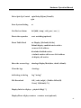
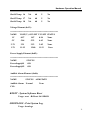
SYS - Print System Information
Usage: sys
Example:
CLI>sys
============================================================
Hardware Revision Information:============================================================
64
Hardware Operation Manual
Vendor ID
:
Model ID
: AXS-8016
Serial No.
: 8888888888888888
Unit Serial No.
:
Expander SAS Address
: 0x5001B4D5060E703F
Product Revision
:0
Expander Chip ID
: 0x0221 (Ports : 28)
Expander Chip Revision
: B3
Customer Code
: 0x2
Manufacturer Data Revision : 0x06 12/08/10
Working Time
: Day00000-00:22:03
Dual Mode
: Single
============================================================
Firmware Revision Information:============================================================
Active Firmware: Active Image
Boot Image:
Revision: 7.01.11.9D 05/25/11
Firmware Family: 1 OemFamily: 0
Fast Boot: No Image Address: 0x14000000
Active Image:
Revision: 7.01.11.9D 05/25/11
Firmware Family: 1 OemFamily: 0
Fast Boot: No Image Address: 0x14080000
Backup Image:
Revision: 7.01.11.9D 05/25/11
65
Hardware Operation Manual
Firmware Family: 1 OemFamily: 0
Fast Boot: No Image Address: 0x14100000
HAL Revision: 0.7.0.0 SES Revision: 0.7.0.0 SCE Revision: 0.7.0.0
Enter “sys” in command line
CLI>sys
This command will show the status of Dual mode of the SAS
Expander:
Single SAS expander: When only 1 SAS Expander inserted
Enter CLI>sys
Dual Mode:Single
Dual SAS Expander: When 2 SAS Expander inserted
SAS Expander 1: enter CLI>sys
Dual Mode: Redundant, I2C Master. CLI Dual
SAS Expander 2: enter CLI>sys
Dual Mode: Redundant, I2C Backup
BU - Operate the Buzzer Attribute
Usage: bu [MUTE]
Example:
CLI>bu
Audible Alarm Element (0x06):
66
Hardware Operation Manual
========================================
NAME
STATUS ALMSTATE
Audible-Alarm
Normal
0
Current Alarm Attribute:
Warning Alarm: Sound2
Critical Alarm:
Sound3
CLI>
turn off buzzer
CLI>bu mute
Alarm beep Muted
CLI>
FAN - Operate the Fan Attribute
Usage : fan
Example:
CLI>fan
Cooling Element (0x03):
========================================
SPEED
NAME CODE RPM STATUS
Fan 01
3
3150
OK
Fan 02
3
3270
OK
Fan 03
3
3120
OK
Fan 04
3
3300
OK
67
Hardware Operation Manual
New FAN Speed Attribute:
Type: Normal
Lowest SpeedCode: 3
Warning SpeedCode: 7
Saved FAN Speed Attribute:
Lowest SpeedCode: 3
Warning SpeedCode: 7
ST - Store System Setting
Usage: st
Example:
CLI>st
ALL Of The User Configurations are Saved.
CLI>
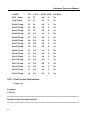
LSD – List Devices Status
Usage: lsd
Example:
CLI>lsd
Show SES elements information
Array Device Element (0x17):
68
Hardware Operation Manual
========================================
NAME
PHY NLR MAX MIN TYPE ADDRESS
SLOT 01
7
6.0G
10
8
SAS
5000C500-103F7AA5
SLOT 02
6
6.0G
10
8
SAS
5000C500-10439631
SLOT 03
11
6.0G
10
8
SAS
5000C500-10438DFD
SLOT 04
10
6.0G
10
8
SATA 5001B4D5-060E700A
SLOT 05
3
6.0G
10
8
SATA 5001B4D5-060E7003
SLOT 06
4
6.0G
10
8
SATA 5001B4D5-060E7004
SLOT 07
12
6.0G
10
8
SATA 5001B4D5-060E700C
SLOT 08
14
6.0G
10
8
SATA 5001B4D5-060E700E
SLOT 09
1
6.0G
10
8
SATA 5001B4D5-060E7001
SLOT 10
2
10
8
SLOT 11
13
10
8
SLOT 12
15
10
8
SLOT 13
5
10
8
SLOT 14
0
10
8
SLOT 15
8
10
8
SLOT 16
9
10
8
Connector Element (0x19):
========================================
NAME
PHY NLR TYPE ROUTE CONNECTED-ADDRESS
Connector00 24
02
Connector00 25
02
Connector00 26
02
Connector00 27
02
Connector01 20 6.0G 02 S 5001B4D5-0163B03F
Connector01 21 6.0G 02 S 5001B4D5-0163B03F
Connector01 22 6.0G 02 S 5001B4D5-0163B03F
Connector01 23 6.0G 02 S 5001B4D5-0163B03F
Connector02 16
02
Connector02 17
02
Connector02 18
02
69
Hardware Operation Manual
Connector02
19
02
Cooling Element (0x03):
========================================
SPEED
NAME
CODE RPM STATUS
Fan 01
3
3120
OK
Fan 02
3
3270
OK
Fan 03
3
3150
OK
Fan 04
3
3300
OK
Temperature Element (0x04):
========================================
NAME
ID CT('C) HTW LTW OTWarn
ENC. Temp
01
27
60
5
No
Chip Temp
02
37
85
5
No
Slot01 Temp 03
27
60
5
No
Slot02 Temp 04
28
60
5
No
Slot03 Temp 05
27
60
5
No
Slot04 Temp 06
27
60
5
No
Slot05 Temp 07
27
60
5
No
Slot06 Temp 08
27
60
5
No
Slot07 Temp 09
27
60
5
No
Slot08 Temp 10
27
60
5
No
Slot09 Temp 11
26
60
5
No
Slot10 Temp 12
NA
60
5
No
Slot11 Temp 13
NA
60
5
No
Slot12 Temp 14
NA
60
5
No
Slot13 Temp 15
NA
60
5
No
70
Hardware Operation Manual
Slot14 Temp 16
NA
60
5
No
Slot15 Temp 17
NA
60
5
No
Slot16 Temp 18
NA
60
5
No
Voltage Element (0x12):
========================================
NAME
VOLT(V) OVLMT UVLMT STATUS
1V
0.97
1.07
0.94
None
5V
5.04
5.32
4.63
None
3.3V
3.21
3.53
3.05
None
12V
11.92
12.80
11.12
None
Power Supply Element (0x02):
========================================
NAME
STATUS
PowerSupply01
OK
PowerSupply02
OK
Audible Alarm Element (0x06):
========================================
NAME
STATUS ALMSTATE
Audible-Alarm Normal
None
CLI>
RESET - System Software Reset
Usage: reset Reset SAS JBOD
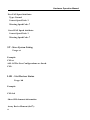
SHOWLOGS - Print System Log.
Usage: showlogs
71
Hardware Operation Manual
CLEARLOGS - Print System Log.
Usage: showlogs
FDL - File DownLoad
Usage: fdl { code | mfgb } offset Upgrade F/W command
Then use XModem/(Checksum) protocol transmit file to update ROM Region
72
Hardware Operation Manual
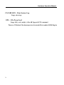
Appendix B
SSA
ASS JJB
BO
OD
D ffiirrm
mw
waarree uuppddaattee pprroocceedduurree
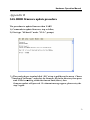
The procedure to update firmware thru UART:
1.) Commands to update firmware, step as follow,
2.) First type "fdl boot 0" under "CLI>" prompt,
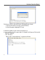
3.) Then under hyper terminal click “file” at top to pull down the menu. Choose
"Xmodem (Checksum)" and select the firmware file in the directory then press
send. If file is receiving within the timeout limit (60sec), then
firmware update will proceed. If a timeout message appear, please retry the
step 2 again.
73
Hardware Operation Manual
The firmware date are presented in the following filename format,
a.) Boot & FW files(boot & code):sas2xfwXXXX.fw
b.) Data file(mfgb): mfgdat6gYYYY.rom
5.) Firmware update can be cancel by pressing Q or q.
6.) After updating boot file, repeat steps 1-5 to update the Firmware File but with
different command.
CLI> fdl code 0
Then use file "sas2xfwXXXX.fw” to update the FW file.
74
Hardware Operation Manual
7.) After updating firmware, repeat steps 1-5 to update the Data File but with
different command.
CLI> fdl mfgb 0
Then use file "mfgdata.rom” to update the Data file.
8.) After updated both files, perform a Power Cycle on the SAS JBOD.
Before upgrade SAS Expander Firmware, all I/O access must be
stopped on the SAS JBOD
Before Performing Power Cycle on the SAS JBOD, Server and
RAID System need to be Power off.
Upgrade Dual SAS Expander :
1.
Perform Steps 1-7 to update Boot & Firmware and Data file on
SAS Expander 1,
2.
Perform Steps 1-7 to update Boot & Firmware and Data file on
SAS Expander 2,
3.
After all files are updated on SAS Expander 1 & 2, perform a
power cycle on SAS JBOD.
75
Hardware Operation Manual
Appendix C
S p e c if ic a t i o n s
Y3-24S6JS6/Y3-16S6JS6/Y3-12S6JS6
Model
Y3-24S6JS6
SAS
Y3-16S6JS6
SAS
Rack mountable
x1
System Type
SAS Expander
Host
Interface
Host Transfer
Rate
Disk Interface
Disk Channel
Hot Swap and
redundant
Hot Spare
Enclosure
Monitoring
(SES)
Remote
Terminal
Configuration
Operating
Systems
Y3-12S6JS6
SAS
One 4 x 6Gb/s SAS Ports, Standard Mini SAS connectors
4 x 6Gb/ Sec per port
SAS 6Gb / SATA 6Gb
16 Bay Disk Channels
24 Bay Disk Channels
12 Bay Disk Channels
Yes (Power Supply, Drive and Fan).
Yes (Drive).
In Band SES via SAS
Yes. Through Terminal port
O/S Independent and Transparent
460+460+460 watts Redundancy
high quality power system, Three
460 watts module with PFC
Power Supply
function. Load sharing type and
cable-less design with
Redundancy Three Power inlet
Electrical
Temperature
Relative
Humidity
Dimensions
76
460+460 watts Redundancy high 400+400 watts Redundancy high
quality power system, two 460 quality power system, two 400
watts module with PFC function. watts module with PFC function.
Load sharing type and cable-less Load sharing type and cable-less
design with Redundancy Dual
design with Redundancy Dual
Power inlet
Power inlet
AC Voltage 100-240 VAC
Ac Frequency 47-63Hz
Operating Temperature: 5 to 35 degree C.
Non Operating Temperature: -40 to 60 degree C.
20% to 80% non-condensing
446.6mm(W)*560mm(D)*4U(H) 446.6mm(W)*560mm(D)*3U(H) 446.6mm(W)*560mm(D)*2U(H)
Hardware Operation Manual
Y3-24S6TS6/Y3-16S6TS6/Y3-12S6TS6
Model
Y3-24S6TS6
SAS
Y3-16S6TS6
SAS
Rack mountable
x2
System Type
SAS Expander
Host
Interface
Host Transfer
Rate
Disk Interface
Disk Channel
Hot Swap and
redundant
Hot Spare
Enclosure
Monitoring
(SES)
Remote
Terminal
Configuration
Operating
Systems
Y3-12S6TS6
SAS
One 4 x 6Gb/s SAS Ports, Standard Mini SAS connectors /per controller
4 x 6Gb/ Sec per port
24 Bay Disk Channels
SAS & NL SAS 6Gb
16 Bay Disk Channels
12 Bay Disk Channels
Yes (SAS Expander, Power Supply, Drive and Fan).
Yes (Drive).
In Band SES via SAS
Yes. Through Terminal port
O/S Independent and Transparent
460+460+460 watts Redundancy
high quality power system, Three
460 watts module with PFC
Power Supply
function. Load sharing type and
cable-less design with
Redundancy Three Power inlet
Electrical
Temperature
Relative
Humidity
Dimensions
460+460 watts Redundancy high 400+400 watts Redundancy high
quality power system, two 460 quality power system, two 400
watts module with PFC function. watts module with PFC function.
Load sharing type and cable-less Load sharing type and cable-less
design with Redundancy Dual
design with Redundancy Dual
Power inlet
Power inlet
AC Voltage 100-240 VAC
Ac Frequency 47-63Hz
Operating Temperature: 5 to 35 degree C.
Non Operating Temperature: -40 to 60 degree C.
20% to 80% non-condensing
446.6mm(W)*560mm(D)*4U(H) 446.6mm(W)*560mm(D)*3U(H) 446.6mm(W)*560mm(D)*2U(H)
77
Hardware Operation Manual
Y3-12S6JS6-D
Model
System Type
SAS Expander
Host
Interface
Host Transfer
Rate
Disk Interface
Disk Channel
Hot Swap and
redundant
Hot Spare
Enclosure
Monitoring
(SES)
Remote
Terminal
Configuration
Operating
Systems
Y3-12S6JS6-D
SAS
Tower
x1
One 4 x 6Gb/s SAS Ports, Standard Mini SAS connectors
4 x 6Gb/ Sec per port
SAS 6Gb / SATA 6Gb
12 Bay Disk Channels
Yes (Power Supply, Drive and Fan).
Yes (Drive).
In Band SES via SAS
Yes. Through Terminal port
O/S Independent and Transparent
400+400 watts Redundancy high quality power system, two 400 watts module with PFC function. Load
sharing type and cable-less design with Redundancy Dual Power inlet
AC Voltage 100-240 VAC
Electrical
Ac Frequency 47-63Hz
Operating Temperature: 5 to 35 degree C.
Temperature
Non Operating Temperature: -40 to 60 degree C.
Relative
20% to 80% non-condensing
Humidity
214mm(W) x 426mm(D) x 439mm(H)
Dimensions
Power Supply
78
Hardware Operation Manual
Y3-12S6AS6
Y3-12S6AS6
SAS
Rack mountable
x1
Model
System Type
SAS Expander
Host
Interface
Host Transfer
Rate
Disk Interface
Disk Channel
Hot Swap and
redundant
Hot Spare
Enclosure
Monitoring
(SES)
Remote
Terminal
Configuration
Operating
Systems
One 4 x 6Gb/s SAS Ports, Standard Mini SAS connectors
4 x 6Gb/ Sec per port
SAS 6Gb / SATA 6Gb
12 Bay Disk Channels
Yes (Power Supply, Drive and Fan).
Yes (Drive).
In Band SES via SAS
Yes. Through Terminal port
O/S Independent and Transparent
12 bays systems: Redundant by dual 375W power modules with PFC feature, loading sharing type and cable-less
Power Supply design
Electrical
Temperature
Relative
Humidity
Dimensions
AC Voltage 100-240 VAC
Ac Frequency 47-63Hz
Operating Temperature: 5 to 35 degree C.
Non Operating Temperature: -40 to 60 degree C.
20% to 80% non-condensing
446.4mm(W)*545mm(D)*2U(H)
*Specification subject to change without notice, all trademarks or
registered trademarks are properties of their respective owners.
79