1
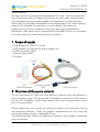
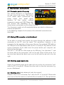
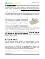
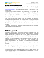
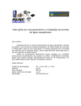
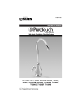
aquacomputer
Version 11/2007
MANUAL AQUASTREAM XT
User- and operating manual for the
aquastream XT pump
aquastream XT™ USB
Firmware-Version 1004
The information contained in this manual is subject to change without prior
notice. All rights reserved.
Current as of: November 2007
© 2007
Aqua Computer GmbH und Co. KG
Gelliehäuser Str. 1 – D-37130 Gleichen - Germany
Page 1
aquacomputer
Version 11/2007
MANUAL AQUASTREAM XT
Table of contents
1. Lieferumfang...................................................................................... 3
2. Übersicht über die Pumpenvarianten..................................................... 3
3. Sicherheitshinweise............................................................................. 4
4. Übersicht über die Pumpe................................................................... 5
5. Montage........................................................................................... 5
6. Elektrische Anschlüsse......................................................................... 6
6.1. Anschlussbereich der aquastream XT...............................................6
6.2. USB Verbindung zum Mainboard herstellen..................................... 6
6.3. Tachosignal-Kabel anschließen.......................................................6
6.4. Lüfter anschließen (nur advanced- und ultra-Variante).......................6
6.6. Durchflusssensor (nur ultra-Variante) oder aquabus (alle Varianten)
anschließen..........................................................................................7
6.7. Interner Wassertemperatursensor (nur ultra-Variante)........................ 7
6.8. Interner Temperatursensor für Steuerplatine..................................... 7
6.9. Steckerbelegung............................................................................8
7. Inbetriebnahme.................................................................................. 9
8. aquasuite Software............................................................................. 9
8.1. Installation der aquasuite Software................................................10
8.2. Fenster „aquastream“...................................................................10
8.3. Fenster „Lüfter“............................................................................11
8.4. Fenster „Pumpen & Durchflusseinstellungen“..................................11
8.5. Fenster „Tachosignal- & Alarmeinstellungen“................................. 12
8.6. Fenster „Sensorkalibrierung“.........................................................13
8.7. Fenster „Erweiterte Pumpeneinstellungen“......................................13
8.8. Fenster „Pumpeninformationen & Schlüsselverwaltung“...................14
8.9. Fenster „XML & Logdaten“............................................................14
8.10. Fenster „Diagramme“.................................................................14
9. Fehlerbehebung............................................................................... 14
9.1. Reset der Pumpeneinstellungen.....................................................14
9.2. Ersatzteile....................................................................................15
10. Technische Daten........................................................................... 16
11. Kontaktmöglichkeiten...................................................................... 16
Page 2
Aqua Computer GmbH und Co. KG
Gelliehäuser Str. 1 – D-37130 Gleichen - Germany
© 2007
aquacomputer
Version 11/2007
MANUAL AQUASTREAM XT
Dear customer,
we thank you for purchasing the aquastream XT pump. You have received a
very high-quality and for longevity built pump for your water cooling system.
The aquastream pump was developed in co-operation with the company
Eheim and is particularly developed for the employment in PC water-cooling
systems. The electronic construction units are laid out for maximum
performance and each component has been thoroughly tested before
distribution. Also each pump is meticulously submitted to a test run; therefore
you might find some moist residue within the pump.
1. Scope of supply
1x aquastream XT USB 12 V pump
1x ATX adapter for starting the power supply unit
1x USB connection cable
1x Speed signal cable
1x Jumper
2. Overview of the pump variants
Of the aquastream XT there are three different variants which are different in
their functional range. The pump and its hardware is identical at all variants.
So e.g. the "standard" variant also contains the internal temperature sensor
but it is not activated.
Which variant you use currently can be find out later in the overview of the of
the aquasuite software. Under the graphic representation of the pump the
variant activated currently is displayed as text.
The following table shows the differences between the standard, advanced
and ultra variant:
© 2007
Aqua Computer GmbH und Co. KG
Gelliehäuser Str. 1 – D-37130 Gleichen - Germany
Page 3
aquacomputer
Feature Comparison
Version 11/2007
MANUAL AQUASTREAM XT
standard
advanced
ultra
Automatic frequency adjustment
•
•
•
Manual frequency adjustment
•
•
•
Deaeration Mode
•
•
•
Rotation detection
•
•
•
Configurable speed signal output
•
•
•
aquabus-interface
•
•
•
Manual configurable fan connector
-
•
•
External temperature sensor connector
-
-
•
Internal water temperature sensor
-
-
•
Freely configurable calibration curves
-
-
•
Temperature controlled fan connector
-
-
•
Flow sensor connector
-
-
•
An upgrade is possible through our web shop. For example, if you want to
upgrade from the standard-variant to the extreme-variant, then you note the
serial number and the public key from the tab "pump information and key
management" of the aquasuite software. You then order the desired upgrade
from the aqua computer onlineshop and enter the serial number and the
public key into the remark field.
3. General notice for usage:
•Save your data before you carry out changes in the PC!
•The pump is not diving capable!
•The rear pump controller mustn't get in contact with water!
•The pump may be used only assembled in a PC case!
•A short rattle noise when starting the pump is normal. If the noise does
not stop for some time, there might be still some air in the pump.
•The pump is not a suction pump. Please make sure that the pump is filled
with water.
•The pump is not suited for dry operation.
•Operate only indoors. Not suited for outdoor operation.
•Care Instructions: Clean the pump only when it is switched off with a
slightly moistened soft cloth.
•This product is not designed for use in life support appliances, devices, or
systems where malfunction of this product can reasonably be expected to
Page 4
Aqua Computer GmbH und Co. KG
Gelliehäuser Str. 1 – D-37130 Gleichen - Germany
© 2007
aquacomputer
Version 11/2007
MANUAL AQUASTREAM XT
result in personal injury. Aqua Computer GmbH & Co. KG customers
using or selling this product for use in such application do so at their own
risk and agree to fully indemnify Aqua Computer GmbH & Co. KG for any
damages resulting from such application.
4. Overview of the pump
5. Assembly
First install the connecting adapters (not included in the scope of supply) to
the aquastream XT. The adapters should be screwed in generally without a
tool until the stop. The black sealing may not be seen any more.
Should you be using a plug-on reservoir tank with the pump (e.g. aquainlet),
then you must remove the silver suction grille and mount the tank directly on
the intake adaptor of the aquastream. In this case no connecting adapter
should be installed on the intake.
If the pump is to be equipped with an uncoupling set, you will first have to
remove the mounting plate from the pump and then fasten the rubber buffers
with the enclosed nuts in the elongated holes of the mounting plate.
© 2007
Aqua Computer GmbH und Co. KG
Gelliehäuser Str. 1 – D-37130 Gleichen - Germany
Page 5
aquacomputer
Version 11/2007
MANUAL AQUASTREAM XT
6. Electronical connections
6.1. Connector panel of the pump
The control electronics is integrated on
the rear side of the pump. The built-in
circuit board offers connectivities for
power supply, fans, speed signal,
aquabus or flow sensor, external
temperature sensor and USB. Please take
into account that depending on the
variant some connections can be without function.
Turn the power supply unit off completely before you attach or disconnect
external components!
In the following chapters the functions of the individual connections are
described.
6.2. Making USB connection to the Mainboard
To be able to control and monitor the pump through the software a USB
connection to the PC must be made. This connection, however, is not
imperative for the operation of the pump. Connect the enclosed USB cable to
the USB port of the Mainboard while the PC is turned off. Pay attention to the
correct orientation of the cable since the pump and/or your computer can
otherwise be damaged.
You see a "1" as well as a little arrow on the USB plug. You find these "1" and
the arrow also at the connection "usb" on the rear sticker of the pump. At a
top view from behind the black wire is on the left and the red wire is on the
right.
6.3. Attaching speed signal cable
Attach the enclosed speed signal cable with one end at the connection "rpm"
while the PC is turned off. Connect the other end to a free fan connector e.g.
on your Mainboard.
6.4. Attaching a fan (only advanced- and ultra-variant)
SAttach a fan to the connection "fan" while the PC is turned off. Please take
into account that the maximum load should not exceed 5 W. The aquastream
Page 6
Aqua Computer GmbH und Co. KG
Gelliehäuser Str. 1 – D-37130 Gleichen - Germany
© 2007
aquacomputer
Version 11/2007
MANUAL AQUASTREAM XT
XT has an excess temperature protection unit so that a switching off is
automatically carried out at a too high load to avoid damages. The output,
however, is not short-circuit proof!
6.5. Attach an external temperature sensor (only ultra-variant)
Attach a 10 kΩ NTC temperature sensor (Order no. 53026) at the
connection "deaeration/ext. temp" while the PC is turned off. Place the sensor
top to the point whose temperature you would like to measure.
Caution: Place the sensor under no circumstances between processor and
cooler! Moreover, do not expose the sensor to any pressure since it is very
sensitive.
6.6. Attaching flow rate sensor (only ultra-variant) or aquabus (all variants)
At the standard and advanced variant the connection "aquabus/flow" is
configured as an aquabus and can be used e.g. To connect the pump to an
optionally available aquaero. A use as a connection for a flow sensor is not
possible at these variants!
This connection is covered with two functions at the ultra variant. In the
delivery state the connection is configured as an aquabus, however, the
aquasuite software can be used to configure the connection to be used with a
flow sensor. A simultaneous use of aquabus and flow sensor is not possible at
the connection. You find details for the available settings in the aquasuite
software on page 11.
The flow sensor and the special interconnecting cable are optional
accessories and can be purchased separately.
6.7. Internal water temperature sensor (only ultra-variant)
The aquastream XT has an internal water temperature sensor which is already
pre-assembled. This sensor can be monitored only in the aquastream XT
ultra-variant.
6.8. Internal temperature sensor for the controller board
The controller board of the aquastream XT is equipped with a pre-assembled
temperature sensor. The advanced- and ultra variant has in addition a twostep protective function to avoid an overload of at the fan connector and a
possible damage to the controller board.
© 2007
Aqua Computer GmbH und Co. KG
Gelliehäuser Str. 1 – D-37130 Gleichen - Germany
Page 7
aquacomputer
Version 11/2007
MANUAL AQUASTREAM XT
The power of the fan connector is put on 100% at a temperature of approx.
70°C to minimize the internal dissipation power. If the temperature increases
nevertheless further, then the performance is put on 0% at a temperature of
approx. 90°C and the connection will be switched off.
In both cases the regulation activates the manual mode until you change the
adjustments by hand.
6.9. Connector pin assignment
Power supply:
Pin 1 +12 V supply
Pin 2 GND
Pin 3 GND
Pin 4 n.c.
Fan output:
Pin 1 GND
Pin 2 0-12 V output voltage
Pin 3 Speed signal
Speed signal output:
Pin 1 GND
Pin 2 n.c.
Pin 3 Open collector speed signal
aquabus/flow rate sensor:
Pin 1 GND
Pin 2 aquabus SDA / flow rate sensor signal
Pin 3 aquabus SCL / flow rate sensor +5 V
USB:
Pin 1
Pin 2
Pin 3
Pin 4
Pin 5
n.c.
GND
D+
D+5 V
External sensor:
Pin 1 GND
Pin 2 Measurement signal
Page 8
Aqua Computer GmbH und Co. KG
Gelliehäuser Str. 1 – D-37130 Gleichen - Germany
© 2007
aquacomputer
Version 11/2007
MANUAL AQUASTREAM XT
7. Inbetriebnahme
First turn off your PC, or remove the main PSU cable if no power-switch is
present. Remove all cables of the PSU (e.g. from non removable disks, optical
storage drives or graphic cards), especially also the 4pin ATX12V power
supply. Attach the pump to the power supply unit with one of the 4-pin Molex
plugs to establish the power supply.
To be able to operate your pump when filling the system, you must now either
start the PC power supply with the enclosed ATX bridging plug or attach the
pump to a second power supply unit.
For starting the power supply unit you put the ATX
bridging plug on the ATX plug of the power supply
unit. The power supply starts after you have put the
plug on. To turn the power supply unit off, you
simply
unplug
the
plug
again.
There is the possibility that your power supply does
not run with the ATX bridging plug. In this case add
CD disk drives and hard disks to the power supply unit.
A red control LED which should flash now is at the lower rear opening at the
pump. If the LED does not flash and shines durably there is an operating
failure . In that case a reset which is described on page 14 can help.
To activate the deaeration mode you put the enclosed jumper on the
connection with the marking "deaeration/ext. Temp". Putting the jumper on
must be carried out while the pump already runs. To end the deaeration
mode you simply remove the jumper again. The pump is in the normal
operating mode now again.
8. aquasuite Software
With the Windows software aquasuite an extensive software is at your
disposal which can be used for all aqua computer products with USB
interface. The software serves the control and monitoring. The installation of
the software is not imperative for the operation of the pump.
Note: Depending on used variant of the aquastream XT, some of the
described functions in the further text are not available in the software. These
can, however, be activated by the acquisition of a key afterwards.
If you change the settings and want to keep them, then you can store these
permanently into the pump by using the function "save settings" in the menu
"aquastream XT".
© 2007
Aqua Computer GmbH und Co. KG
Gelliehäuser Str. 1 – D-37130 Gleichen - Germany
Page 9
aquacomputer
Version 11/2007
MANUAL AQUASTREAM XT
8.1. Installation der aquasuite Software
To be able to control and monitor the aquastream XT over a Windows(1) PC,
we offer the aquasuite software as a free download on our website
www.aqua-computer.de. You find the latest version of the software in the
support area.
In addition you need the Microsoft(1) .NET framework(1) 2.0 or higher. You
find this this also in our download area. If you use Windows Vista(1), you do
not need this program, since it is already integrated into the operating system.
Please install the Microsoft(1) .NET framework(1) first and if necessary restart the
computer. If the program creates a new user account you can just delete it in
the control panel.
Then install the aquasuite software. After the installation the aquasuite
software is immediately ready for use. Depending on the chosen settings the
aquasuite starts at the next restart automatically or can be started via the icon
on the desktop or through the start menu.
The following sites describe the functions of each window in the aquasuite
software.
(1)
Microsoft, Windows, .NET framework and Windows Vista are registered
trademarks of Microsoft Corporation.
8.2. Window „aquastream“
You see all important data summarized compactly in the main view. The
graphic representation of the pump shows the water temperature on the left
and on the right side the water flow rate if a ultra variant of the pump is used
and an optionally available flow sensor was attached to the pump.
A ring-like indicator within the pump shows information about the adjusted
frequency with its blue segments. The more blue segments are visible, the
higher the frequency of the pump is. You find a similar indication in the
graphic representation of the ventilator. The segments show information
about the adjusted performance here.
The output voltage as well as the performance is displayed above the
ventilator.
The scale on the right side shows the temperature of the optionally available
external sensor. The little red triangle marks the adjusted alarm temperature.
General operating data of the pump can be found in the upper left field. The
current status of the pump as well as possible faults are displayed in the field
at the end of the window.
Page 10
Aqua Computer GmbH und Co. KG
Gelliehäuser Str. 1 – D-37130 Gleichen - Germany
© 2007
aquacomputer
Version 11/2007
MANUAL AQUASTREAM XT
8.3. Window „Fan“
In this window you are able to choose whether the fan shall be regulated
manually or automatically into dependence of a temperature and further
parameters. At the manual setting activate the "manual power adjustment"
and simply use the slider to adjust the power while for the option "temperature
control" the temperature of the external temperature sensor or the internal
water temperature sensor is used for an automatic regulation. You can
choose freely which sensor should be used for the regulation.
You can influence all parameters by hand which are connected with the
automatic fan regulation in the field temperature regulator. Inexperienced
users can alternatively choose one of the predefined profiles.
On the right side two scales gives information about the output voltage of the
fan header as well as the adjusted power. Moreover, the currently measured
speed of the fan is displayed under the scale.
8.4. Windows „Pump and flow rate settings“
Here you can select whether the pump shall be controlled automatically or
manually.
At the "automatic frequency settings" the frequency of the pump is
automatically set to the highest possible frequency. To this the electronics of
the pump determines permanently the position of the rotor, current
consumption, performance as well as the voltage and calculates the optimal
operating point out of this independently. To this is the frequency repeatedly
tries to get as high as possible at a stable operation. Depending on the
resistance of a system the frequency of the pumps reaches approx. 75 - 85
Hz in a normal loop.
You can adjust the pump frequency manually at the "manual frequency
settings". If the chosen value is not attainable, then the pump tries to adjust
the highest possible frequency (below your target frequency) like in the case
of the automatic frequency setting.
With the button "reset maximum pump frequency" the maximum frequency
found out currently is rejected in the automatic and in the manual mode and
the pump tries once more to find the maximum frequency.
This process also can be automated by activating that the frequency shall be
reset automatically after X minutes.
The automatic deaeration of the pump can be actievated through the option
"activate deaeration mode". In the delivery state the deaeration by jumper is
predefined as described at the beginning. To be able to start the deaeration
© 2007
Aqua Computer GmbH und Co. KG
Gelliehäuser Str. 1 – D-37130 Gleichen - Germany
Page 11
aquacomputer
Version 11/2007
MANUAL AQUASTREAM XT
mode by jumper the option "activate by jumper mode (ext. Temperature)"
must be deactivated.
If you like to use a flow sensor, then you activate this flow sensor through the
button "flow rate sensor active". You can adjust settings for the flow sensor
and also see the current measured flow value in the lower area.
The other way you can activate the aquabus with the checkbox "aquabus
active". Moreover, the "aquabus address" can be changed, what becomes
necessary if you would like to attach two aquastream XT pumps by aquabus
to an aquaero.
In addition, if you want to control the aquastream XT through the aquaero,
you activate the option "prefer aquabus communication". Without this setting
the aquaero can only readout the pump. All other operating settings must be
carried out via the aquasuite software.
A restart of the pump must be carried out if you change the aquabus address
or reconfigure the connector. In this case, shut down your computer, wait for
a few seconds and switch it on again.
8.5. Window „Speed signal and alarm settings“
The aquastream XT evaluates various values over calculations as well as
sensors which can be put on an alarm. The rear status LED shines
permanently red at malfunctions or when an alarm value has been exceeded
or fallen below. If a speed signal cable is attached it is possible to "switch off
the speed signal in case of an alarm". The switching off only works when in
the configuration of the speed signal output the output of a static speed
signal was selected (with specification for revolutions per minute). In the other
three modes the signal of the fan, the flow sensor or the pump is always
forwarded independently of an alarm.
In the "alarm settings for speed signal output" you can define at which values
an alarm shall be given out. You can set upper respectively lower limits for
the external and internal temperature sensor as well as for the flow sensor.
The "current alarms" always displays all alarms which were established
independently of the alarm settings.
The number of measuring impulses indicates over which time period the
speed of the fan shall be determined. High values deliver very exact values
which are, however, updated only slowly. Small values accelerate the
measuring but measurement results are more inaccurate.
Page 12
Aqua Computer GmbH und Co. KG
Gelliehäuser Str. 1 – D-37130 Gleichen - Germany
© 2007
aquacomputer
Version 11/2007
MANUAL AQUASTREAM XT
8.6. Window „Sensor calibration“
In the upper area you see a summary of the measured temperatures for all
three sensors.
The firmware of the aquastream XT contains a pre-calibrated temperature
curve for each temperature sensor. In case that the measured temperature
differs from the real temperature, experienced users can do a correction in
this window. Usually no correction should be necessary. At first select the
desired sensor. You can then adjust the associated ADC value for every
predefined temperature and therefore change the course of the calibration
curve. The curve is immediately updated at changes and you can immediately
check the temperature calculated from the new values, too. To guarantee a
continuous precision, it might be necessary to calibrate several points.
To restore the original temperature curves click on the button "load default
values in the lower left corner". Your individual settings will be deleted and
replaced with the default curves.
8.7. Windows „Extended pump settings“
The extended pump settings are deactivated at all pumps and can be
activated only with a key which can be ordered free of charge. This key
exclusively activates the extended functions and does not have influence on
the functions of the individual aquastream variants.
WARNING: the extended pump settings partly engage deeply in the drive of
the pump and can damage the pump and its controller irreparably. We take
no responsibility for damages to the pump or possible resultant damages to
hardware and software.
When asking for a key this will be noted in a database and you will lose the
guarantee!
8.8. Window „Pump information and key management“
Besides general data of the pump and the fan you also find the key
management here which determines which function range certainly is
activated. For activation of another variant you need the serial number and
the public key of the pump. Both must be wrote in the remark field of the
shop when you order an upgrade. You find more information regarding the
different pump variants on page 4.
© 2007
Aqua Computer GmbH und Co. KG
Gelliehäuser Str. 1 – D-37130 Gleichen - Germany
Page 13
aquacomputer
Version 11/2007
MANUAL AQUASTREAM XT
8.9. Window „XML & logdata“
The aquasuite offers extensive protocol and evaluation functions. To use
these, the log function must be switched on. Also set the interval in which the
data shall be saved in the database of the aquasuite.
In the menu "extra" you are able to analyze the log data. Select the pump
from the device list and click on the button "load data". Then drag the desired
values from the right list to the left into the diagram and select a colour.
To be able to use the values from the aquasuite software in other
programmes, these can be stored into a XML file. Activate the option "start
automatic data export" and set a refresh interval as well as an output file.
8.10. Window „Diagrams“
The chart window represents the most important values like temperatures,
pump-, regulator- and fan data graphically. The desired values can be
selected below. Time periods can be marked and extended or reduced by
mouse wheel within the diagram.
9. Trouble shooting
9.1. Reset of the pump values
There are two ways to put the pump into its delivery state. This makes sense if
the pump no longer works correctly or you have set nonsensical values in the
aquasuite and have stored them into the pump.
You can reset the pump by software via the aquasuite software by selecting
the menu item "set factory defaults" in the aquasuite software from the menu
"aquastream XT".
The pump can alternatively be reset also directly by a jumper, what at serious
problems is recommendable. To do that turn off the computer and put the
enclosed jumper on the connection "deaeration / ext. temp". Switch on the
computer again and remove the jumper.
9.2. Spare parts
Item numbers of the original spare parts and accessories for the aquastream
XT pump :
Description
Item number
Aqua Computer
Connection cable for aquabus/tacho
93111
ATX-short-circuit-plug
93112
Page 14
Aqua Computer GmbH und Co. KG
Gelliehäuser Str. 1 – D-37130 Gleichen - Germany
© 2007
aquacomputer
Pump-Controller
Pumpe without controller
Version 11/2007
MANUAL AQUASTREAM XT
95103
93086
The following original Eheim spare parts can be used with the pump:
Description
Pump cover
Replacement gasket for
pump cover
Replacement axis incl.
rubbers
Impeller set incl. axis
Fixing plate
Item number
Aqua Computer
41032
92014
Item number Eheim
41031
7433720
41065
41036
Not compatible!
7264509
7439909
7263550
Of course you can obtain all spare parts from us. Eheim spare parts can in
addition be purchased in the local aquarium specialised trade.
10. Technical data
Power supply:
Current consumption of pump:
Maximum pressure :
USB compatibility:
Temperature measurement :
Fan output voltage:
Fan output current:
Speed signal output:
ambient temperature:
12 V +/-5%
500 mA to 1,5 A (max.18 W)
4,2 m water column
1.1 and 2.0
NTC 10 kΩ, max. absolute tolerance 2 °C
0-12 V (load-dependent)
0 – 0,4 A (5 W)
open collector output
10 °C – 40 ° C
Compatible flow sensors:
5 V VDD, maximum 50 mA
open collector signal output
Flow signal duty cycle 1:1
100-3000 Impulse/Liter
© 2007
Aqua Computer GmbH und Co. KG
Gelliehäuser Str. 1 – D-37130 Gleichen - Germany
Page 15
aquacomputer
Version 11/2007
MANUAL AQUASTREAM XT
11. Contact
Für Fragen zu unseren Produkten stehen wir Ihnen selbstverständlich gerne
zur Verfügung. Antworten auf einige häufige Fragen finden Sie auf unserer
Website www.aqua-computer.de im Bereich Support unter „faq“. Außerdem
finden Sie in unserem Online-Forum rund um die Uhr Kontakt zu anderen
Benutzern und erfahrenen Moderatoren, mit denen Sie sich über unsere
Produkte austauschen können.
Um einen direkten Kontakt zu uns aufzunehmen, stehen Ihnen verschiedene
Möglichkeiten zur Verfügung:
email: [email protected].
Postanschrift:
Aqua Computer GmbH & Co. KG
Gelliehäuser Str. 1
37130 Gleichen OT Benniehausen
Deutschland
Tel:
Fax:
Page 16
+49 (0) 5508 9749290 (9-15 Uhr)
+49 (0) 5508 9749291
Aqua Computer GmbH und Co. KG
Gelliehäuser Str. 1 – D-37130 Gleichen - Germany
© 2007