1
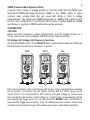
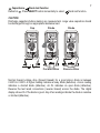
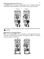
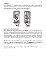
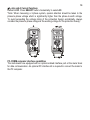
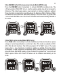
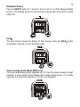
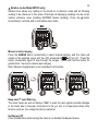
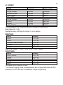
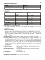
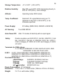
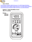
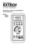
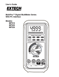
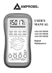
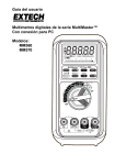
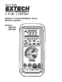
User’s Guide
MultiPro™ Digital MultiMeter Series
With PC Interface
Models:
MP510A
MP530A
00
1
21
3
42
5
63
A
7
84
9
105
2
1) SAFETY
Terms in this manual
WARNING identifies conditions and actions that could result in serious injury or even
death to the user.
CAUTION identifies conditions and actions that could cause damage or malfunction
in the instrument.
This manual contains information and warnings that must be followed for operating the
instrument safely and maintaining the instrument in a safe operating condition. If the
instrument is used in a manner not specified by the manufacturer, the protection
provided by the instrument may be impaired. The meter is intended only for indoor use.
The meter protection rating, against the users, is double insulation per IEC61010-1 2nd
Ed., EN61010-1 2nd Ed., UL61010-1 2nd Ed. and CAN/CSA C22.2 No. 61010.1-0.92
to Category III 1000 Volts AC & DC and Category IV 600 Volts AC & DC.
Terminals (to COM) measurement category:
V / A / mAμA : Category III 1000 Volts AC & DC, and Category IV 600 Volts AC & DC.
Per IEC61010-1 2nd Ed. (2001) Measurement Category
Measurement Category IV (CAT IV) is for measurements performed at the source of
the low-voltage installation. Examples are electricity meters and measurements on
primary overcurrent protection devices and ripple control units.
Measurement Category III (CAT III) is for measurements performed in the building
installation. Examples are measurements on distribution boards, circuit- breakers,
wiring, including cables, bus-bars, junction boxes, switches, socket-outlets in the fixed
installation, and equipment for industrial use and some other equipment, for example,
stationary motors with permanent connection to the fixed installation.
Measurement Category II (CAT II) is for measurements performed on circuits directly
connected to the low voltage installation. Examples are measurements on household
appliances, portable tools and similar equipment.
3
WARNING
To reduce the risk of fire or electric shock, do not expose this product to rain or
moisture. To avoid electrical shock hazard, observe the proper safety precautions
when working with voltages above 60 VDC or 30 VAC rms. These voltage levels pose
a potential shock hazard to the user. Do not touch test lead tips or the circuit being
tested while power is applied to the circuit being measured. Keep your fingers behind
the finger guards of the test leads during measurement. Inspect test leads, connectors,
and probes for damaged insulation or exposed metal before using the instrument. If
any defects are found, replace them immediately. Do not measure any current that
exceeds the current rating of the protection fuse. Do not attempt a current
measurement to any circuit where the open circuit voltage is above the protection fuse
voltage rating. Suspected open circuit voltage should be checked with voltage
functions. Never attempt a voltage measurement with the test lead inserted into the
μA/mA or A input jack. Only replace the blown fuse with the proper rating as specified
in this manual.
CAUTION
Disconnect the test leads from the test points before changing functions. Always set
the instrument to the highest range and work downward for an unknown value when
using manual ranging mode.
INTERNATIONAL ELECTRICAL SYMBOLS
Caution ! Refer to the explanation in this Manual
!
Caution ! Risk of electric shock
Earth (Ground)
Double Insulation or Reinforced insulation
Fuse
AC--Alternating Current
DC--Direct Current
2) CENELEC DIRECTIVES
The instruments conform to CENELEC Low-voltage directive 2006/95/EC and
Electromagnetic compatibility directive 2004/108/EC
4
3) PRODUCT DESCRIPTION
Panel Illustration
1) 5000 count LCD display
1
00
1
21
3
42
5
63
7
84
9
105
2
A
3
4
5
6
7
2) Push-buttons for special
functions & features
3) Selector to turn the
Power On or Off and Select
a function
4) Input Jack for 10A (20A
for 30sec) current function
5) Input Jack for all
functions EXCEPT current
(μA, mA, A) functions
6) Common (Ground
reference) Input Jack for all
functions
7) Input Jack for milli-amp
and micro-amp current
functions
5
Analog bar-graph
The analog bar graph provides a visual indication of measurement like a traditional
analog meter needle. It is excellent for detecting faulty contacts, identifying
potentiometer clicks, and indicating signal spikes during adjustments.
Average sensing RMS calibrated
RMS (Root-Mean-Square) is the term used to describe the effective or equivalent DC
value of an AC signal. Most digital multimeters use average sensing RMS calibrated
technique to measure RMS values of AC signals. This technique is to obtain the
average value by rectifying and filtering the AC signal. The average value is then
scaled upward (calibrated) to read the RMS value of a sine wave. In measuring pure
sinusoidal waveforms, this technique is fast, accurate and cost effective. In measuring
non-sinusoidal waveforms, however, significant errors can be introduced because of
different scaling factors relating average to RMS values.
True RMS
True RMS is a term which identifies a DMM that responds accurately to the effective
RMS value regardless of the waveforms such as: square, sawtooth, triangle, pulse
trains, spikes, as well as distorted waveforms with the presence of harmonics.
Harmonics may cause :
1)Overheating in transformers, generators and motors
2)Circuit breakers to trip prematurely
3)Fuses to blow
4)Neutrals to overheat due to the triplen harmonics present on the neutral
5)Bus bars and electrical panels to vibrate
Crest Factor
Crest Factor is the ratio of the Crest (instantaneous peak) value to the True RMS
value, and is commonly used to define the dynamic range of a True RMS DMM. A pure
sinusoidal waveform has a Crest Factor of 1.4. A badly distorted sinusoidal waveform
normally has a much higher Crest Factor.
NMRR (Normal Mode Rejection Ratio)
NMRR is the DMM's ability to reject unwanted AC noise effects that can cause
inaccurate DC measurements. NMRR is typically specified in terms of dB (decibel).
This series has a NMRR specification of >60dB at 50 and 60Hz, which means a good
ability to reject the effect of AC noise in DC measurements.
6
CMRR (Common Mode Rejection Ratio)
Common mode voltage is voltage present on both the COM and VOLTAGE input
terminals of a DMM, with respect to ground. CMRR is the DMM's ability to reject
common mode voltage effect that can cause digit rolling or offset in voltage
measurements. This series has a CMRR specification of >60dB at DC to 60Hz in ACV
function; and >120dB at DC, 50 and 60Hz in DCV function. If neither NMRR nor CMRR
specification is specified, a DMM's performance will be uncertain.
4) OPERATION
CAUTION
Before and after hazardous voltage measurements, test the voltage function on a
known source such as line voltage to determine proper meter functioning.
DC Voltage, AC Voltage, & Hz Frequency functions
mV function defaults at DC. Press SELECT button momentarily to select AC. Press the
Hz push-button momentarily to activate or to exit Hz.
DCV
A
ACV
A
Hz
A
Note: Input sensitivity varies automatically with function range selected before activating
the Hz function. mV function has the highest (300mV) and the 1000V range has the
lowest (300V). It is recommended to first measure the signal voltage (or current) level
then activate the Hz function in that voltage (or current) range to automatically set the
most appropriate trigger level. You can also press the RANGE button momentarily to
select another trigger level manually. If the Hz reading becomes unstable, select lower
sensitivity to avoid electrical noise. If the reading shows zero, select higher sensitivity.
Capacitance,
Diode test function
Default at . Press SELECT button momentarily to select
7
Diode test function.
CAUTION
Discharge capacitors before making any measurement. Large value capacitors should
be discharged through an appropriate resistance load.
Cap
A
Diode
A
Forward Bias
Diode
A
Reverse Bias
Normal forward voltage drop (forward biased) for a good silicon diode is between
0.400V to 0.900V. A higher reading indicates a leaky diode (defective). A zero reading
indicates a shorted diode (defective). An OL indicates an open diode (defective).
Reverse the test leads connections (reverse biased) across the diode. The digital
display shows OL if the diode is good. Any other readings indicate the diode is resistive
or shorted (defective).
8
Temperature function (Model MP530 only)
Press SELECT button momentarily to toggle between °C and °F readings, and the new
setting will be saved automatically in the non-volatile memory as power up default.
K-temp
A
K-temp
A
Note: Be sure to insert the banana plug K-type temperature bead probe with correct
polarities.
Ω Resistance, Continuity functions
Default at Ω. Press SELECT button momentarily to select Continuity function,
convenient for checking wiring connections and operation of switches. A continuous
beep tone indicates a complete wire.
A
A
9
CAUTION
Using resistance and continuity function in a live circuit will produce false results and
may damage the instrument. In many cases the suspected component must be
disconnected from the circuit to obtain an accurate reading
Ω
Ω
A
A
3 Sec
Auto leads resistance calibration
When entering the 50Ω range manually by RANGE button for high precision low
resistance measurement, this feature will prompt to short the inputs for calibration. The
display shows “Shrt”. Simply short the leads for 3 seconds until the display shows zero,
then the resistance in the leads and in the internal protection circuitry of the meter is
compensated automatically. The compensation value can be as much as 5Ω. If a
compensation value that is higher than that is needed, Relative mode is recommended.
The shortcut is to short the test leads in auto-ranging resistance mode until the meter
enters the lowest 50Ω range automatically, press the RANGE button momentarily to
get the “Shrt” prompt, then wait 3 more seconds until the display shows zero.
Note: The calibration stays until the range is changed, the function is changed, or autoranging mode is selected.
10
μA, mA, and A Current functions
Default at DC. Press SELECT button momentarily to select AC.
*Note: When measuring a 3-phase system, special attention should be taken to the
phase-to-phase voltage which is significantly higher than the phase-to-earth voltage.
To avoid exceeding the voltage rating of the protection fuse(s) accidentally, always
consider the phase-to-phase voltage as the working voltage for the protection fuse(s).
A
A
PC-COMM computer interface capabilities
The instruments are equipped with an optical isolated interface port at the meter back
for data communication. An optional PC interface kit is required to connect the meter to
the PC computer.
11
50ms MAX/MIN at fast 20/s measurement mode (Model MP530 only)
Press the MAX/MIN button momentarily to activate MAX/MIN recording mode. The
LCD annunciators “MAX MIN” turn on, and the reading update rate will be increased to
20/second. The meter beeps when a new maximum or minimum reading is updated.
Press the button momentarily to read throughout the Maximum (MAX), Minimum (MIN),
and Maximum minus Minimum (MAX-MIN) readings. Press the button for greater than
1 second exit MAX/MIN mode. Auto Power Off feature will be automatically disabled in
this mode.
0.8ms PEAK capture mode (Model MP530 only)
Press PEAK button momentarily to activate Instantaneous Peak-Hold mode to capture
voltage or current signal duration as short as 0.8ms. This mode is available in DCV,
ACV, DCA, & ACA functions. The LCD annunciators “C” & “MAX” turn on. The meter
beeps when a new maximum or minimum reading is updated. Press the button
momentarily to read throughout the Maximum (MAX), Minimum (MIN), and Maximum
minus Minimum (MAX-MIN) readings. Press the button for greater than 1 second to exit
PEAK capture mode. Auto Power Off feature will be disabled automatically in this
mode.
12
Backlighted display
Press the SELECT button for 1 second or more to turn on or off the display backlight
function. The backlight will also be turned off automatically after 30 seconds to extend
battery life.
Hold
The hold function freezes the display for later viewing. Press the HOLD
momentarily to activate or to exit the hold function
button
Zoom 5x analog pointer (Model MP530 only)
The Zoom mode analog pointer magnifies up to 5 times the regular analog bar graph
resolution to show minute signal changes with a single analog pointer. It is virtually
equivalent to the bar graph resolution of 5 X 50 = 250 segments.
13
Relative mode (Model MP530 only)
Relative zero allows any reading to be stored as a reference value and all following
reading to be reference to that value. Practically all displaying readings can be set as
relative reference value including MAX/MIN feature readings. Press the button
momentarily to activate and to exit relative zero mode.
Manual or Auto-ranging
Press the RANGE button momentarily to select manual-ranging, and the meter will
remain in the selected range and the LCD annunciator
will turn off. Press the
button momentarily again to step through the ranges. Press and hold the button for
greater than 1 second to resume auto-ranging.
Note: Manual ranging feature is not available in Hz function.
Beep-Jack™ Input Warning
The meter beeps as well as displays “InEr” to warn the user against possible damage
to the meter due to improper connections to the μA, mA, or A input jacks when other
function (such as the voltage function) is selected.
Set Beeper Off
Press the Hz button while turning the meter on to disable the Beeper feature.
14
Auto Power Off (APO)
The Auto Power Off (APO) mode turns the meter off automatically to extend battery life
after approximately 17 minutes of no activity. Activities are specified as: 1) Rotary
switch or push button operations, and 2) Significant measuring readings of above 10%
of range or non-OL Ω readings. That is, the meter will intelligently avoid entering the
APO mode when it is under normal measurements. To wake up the meter from APO,
press the SELECT button momentarily or turn the rotary switch to the OFF position and
then turn back on again. Always turn the rotary switch to the OFF position when the
meter is not in use
Disabling Auto Power Off
Press the RANGE button while turning the meter on to disable the Auto Power Off
(APO) feature.
5) MAINTENANCE
WARNING
To avoid electrical shock, disconnect the meter from any circuit, remove the test leads
from the input jacks and turn OFF the meter before opening the case. Do not operate
with open case. Install only the same type of fuse or equivalent
Turn-On diagnostics
If self-diagnostic message “rE-O” is displayed while powering on the meter, do not
switch off the meter off. The meter will quickly complete the task and return to normal
operation. However, if self-diagnostic message “C_Er” is displayed while powering on,
some meter ranges may be significantly out of specification. To avoid measurement
errors, stop using the meter and send it in for re-calibration. Refer to the WARRANTY
section for obtaining warranty or repair service.
Cleaning and Storage
Periodically wipe the case with a damp cloth and mild detergent; do not use abrasives
or solvents. If the meter is not to be used for periods longer than 60 days, remove the
battery and store it separately
15
Trouble Shooting
If the instrument fails to operate, check battery, fuses, leads, etc., and replace as
necessary. Double check operating procedure as described in this user’s manual
If the instrument voltage-resistance input terminal is subjected to accidental high
voltage transient the series fusible resistors will blow (become high impedance), like
standard fuses, to protect the user and the instrument. Most measuring functions
through this terminal will then be an open circuit. The series fusible resistors and the
spark gaps should only be replaced by qualified technician. Refer to the WARRANTY
section for obtaining warranty or repairing service.
Battery and Fuse replacement
Battery use:
Single 9V battery NEDA1604, JIS006P or IEC6F22;
or 9V alkaline battery NEDA1604A, JIS6AM6 or IEC6LF22
Fuses:
Fuse (FS1) for μAmA current input: 0.44A/1000V, IR 10kA or better, F fuse
Fuse (FS2) for A current input: 11A/1000V, IR 20kA or better, F fuse
Battery replacement for models with battery access door:
Loosen the 2 screws from the battery access door of the case bottom. Lift the battery
access door and thus the battery compartment up. Replace the battery. Re-fasten the
screws.
Fuse replacement (and also Battery
replacement for splash proof version
without battery access door):
Loosen the 4 screws from the case
bottom. Lift the end of the case bottom
nearest the input jacks until it unsnaps
from the case top. Replace the blown
fuse(s) and/or the battery. Replace the
case bottom, and ensure that all the
gaskets are properly seated and the two
snaps on the case top (near the LCD
side) are engaged. Re-fasten the screws.
(6) SPECIFICATIONS
DC VOLTAGE
RANGE
Accuracy
50.00 mV
0.12% + 2d
500.0 mV
0.06% + 2d
5.000V, 50.00V, 500.0V, 1000V
0.08% + 2d
NMRR: >60dB @ 50/60Hz, CMRR: >120dB @ DC, 50/60Hz, Rs=1kΩ
Input impedance: 10MΩ, 16pF nominal (44pF nominal for 50mV & 500mV ranges)
AC VOLTAGE
Accuracy
RANGE
50Hz/60Hz
50.00mV, 500.0mV, 5.000V, 50.00V, 500.0V, 1000V
0.5% + 3d
40Hz to 500Hz
50.00mV, 500.0mV
0.8% + 3d
5.000V, 50.00V, 500.0V
1.0% + 4d
1000V
1.2% + 4d
Up to 20kHz
50.00mV, 500.0mV
0.5dB*
5.000V, 50.00V, 500.0V
3dB*
1000V
Unspecified
*Specified from 30% to 100% of range
CMRR: >60dB @ DC to 60Hz, Rs=1kΩ
Input Impedance: 10MΩ, 16pF nominal (44pF nominal for 50mV & 500mV ranges)
DC CURRENT
RANGE
Accuracy
Burden Voltage
500.0μA, 5000μA
0.15mV/μA
0.2% + 4d
50.00mA, 500.0mA
3.3mV/mA
5.000A, 10.00A*
45mV/A
*10A continuous, 20A for 30 seconds max with a 5 minute cool down interval
16
AC CURRENT
RANGE
Accuracy
Burden Voltage
50 / 60Hz
0.6%+3d
500.0μA, 5000μA
0.15mV/μA
50.00mA, 500.0mA
0.6%+3d
3.3mV/mA
5.000A, 10.00A*
0.6%+3d
45mV/A
40Hz to 1kHz
0.8%+4d
500.0μA, 5000μA
0.15mV/μA
50.00mA
0.8%+4d
3.3mV/mA
500.0mA
1.0%+4d
3.3mV/mA
5.000A, 10.00A*
0.8%+4d
45mV/A
*10A continuous, 20A for 30-second max with 5 minutes cool down interval
Peak Capture (for V & A)
Specified accuracy ±150 digits for changes > 5 ms in duration
RESISTANCE
RANGE
Accuracy
0.3% + 6d
50.00Ω
0.1% + 3d
500.0Ω
0.1% + 2d
5.000kΩ, 50.00kΩ, 500.0kΩ
0.4% + 3d
5.000MΩ
2.0% + 5d
50.00MΩ
Open Circuit Voltage: < 1.3VDC (< 3VDC for 50Ω & 500Ω ranges)
CAPACITANCE
RANGE
Accuracy*
50.00nF, 500.0nF
0.8% + 3d
1.0% + 3d
5.000μF
2.0% + 3d
50.00μF
3.5% + 5d
500.0μF**
5.0% + 5d
9999μF**
*Accuracies with film capacitor or better
**In manual ranging mode, measurements are not specified below 45.0μF
and 450μF for the 500.0μF and 9999μF ranges respectively
17
TEMPERATURE (MP530 ONLY)
RANGE
-50°C TO 1000°C
-58°F TO 1832°F
18
Accuracy
0.3% + 3d
0.3% + 6d
FREQUENCY
Function
Sensitivity
Range
(ACrms)
mV
300mV
10Hz - 125kHz
5V
2V
10Hz - 125kHz
50V
20V
10Hz - 20kHz
500V
80V
10Hz - 1kHz
1000V
300V
10Hz - 1kHz
300mV
10Hz - 125kHz
Ω, Cx, diode
10% F.S.
10Hz - 125kHz
μA, mA, A
Peak mode for V & A functions
Accuracy: Specified accuracy ±150 digits for changes > 0.8 ms in
duration
Audible Continuity:
Measurement threshold: Beeper will sound if measurement is below 20 .
Beeper will not sound if measurement is above 200 . Beeper may or
may not sound if measurement is between 20 and 200 . Response
time: < 100μs
Diode Test: Typical test current; 0.4mA, open circuit voltage; <3.5VDC
Accuracy Notes: Accuracy is ± (% reading digits + number of digits), or as
otherwise specified, at 23°C ±5°C < 75% R.H. True RMS accuracies are
specified from 5% to 100% of range or as otherwise specified. Maximum
Crest Factor <3:1 at full scale & <6:1 at half scale (with frequency
component within the specified frequency bandwidth for non-sinusoidal
waveforms).
Digital Display:
5000-count LCD display; 5 per second nominal
refresh rate
Bar Graph Display:
52-segment bargraph; 60 per second nominal
refresh rate
Low Battery:
Below approx. 7V
Operating Temperature: 32° to 113°F (0° to 45°C)
o
19
Storage Temperature:
-4° to 140°F (-20 to 60 C)
Relative Humidity:
Max 80% up to 87ºF (31ºC) decreasing linearly to
50% at 113ºF(45ºC): <80% storage
Altitude:
Operating below 2000 meters
Temp. Coefficient:
Nominal 0.15 x specified accuracy per ºC
(between 0 and 18oC or 28 to 50oC), or as
otherwise specified
Power Supply:
9V battery (NEDA1604, JIS006P or IEC6F22)
AC Sensing:
True RMS MP530
Auto Power Off:
After 17 minutes of inactivity with no input signal
Safety:
Double insulation per IEC61010-1 2nd Ed., EN61010-1 2nd
Ed., UL61010-1 2nd Ed. & CAN/CSA C22.2 No. 61010.10.92 to Category III 1000V AC & DC and Category IV 600V
AC & DC
Terminals (to COM) ratings:
V / A / MAμA:CATEGORY III 1000 VOLTS AC & DC, AND
CATEGORY IV 600 VOLTS AC & DC.
E.M.C.: E.M.C.: Meets EN61326-1:2006 (EN55022, EN61000-3-2,
EN61000-3-3, EN61000-4-2, EN61000-4-3, EN61000-4-4, ,
EN61000-4-5, EN61000-4-6, EN61000-4-8, EN61000-4-11)
Overload Protection:
µA/mA Range:
0.63/500V, IR 200kA, Fast fuse.
A Range:
12.5A/500V IR 20kA, Fast fuse.
V Range:
1050V rms, 1450V peak
mV, Ω and other: 600VDC/VAC rms
Power Consumption: 2.7 mA typical
Dimension: 7.32 x 3.43 x 1.4" with holster (186mm x 87mm x 35.5mm)
Weight:
15.17 oz. with holster (430g)
WARRANTY
20
EXTECH INSTRUMENTS CORPORATION (A FLIR COMPANY) warrants this
instrument to be free of defects in parts and workmanship for three years
from date of shipment (a six month limited warranty applies to sensors and
cables). If it should become necessary to return the instrument for service
during or beyond the warranty period, contact the Customer Service
Department at (781) 890-7440 ext. 210 for authorization or visit our
website www.extech.com for contact information. A Return Authorization
(RA) number must be issued before any product is returned to Extech. The
sender is responsible for shipping charges, freight, insurance and proper
packaging to prevent damage in transit. This warranty does not apply to
defects resulting from action of the user such as misuse, improper wiring,
operation outside of specification, improper maintenance or repair, or
unauthorized modification. Extech specifically disclaims any implied
warranties or merchantability or fitness for a specific purpose and will not
be liable for any direct, indirect, incidental or consequential damages.
Extech's total liability is limited to repair or replacement of the product. The
warranty set forth above is inclusive and no other warranty, whether
written or oral, is expressed or implied.
Calibration and Repair Services
Extech offers repair and calibration services for the products we sell.
Extech also provides NIST certification for most products. Call the
Customer Care Department for information on calibration services
available for this product. Extech recommends that annual calibrations be
performed to verify meter performance and accuracy.
Support line (781) 890-7440
Technical Support: Extension 200; E-mail: [email protected]
Repair & Returns: Extension 210; E-mail: [email protected]
Product specifications subject to change without notice
For the latest version of this User Guide, Software updates, and other
up-to-the-minute product information, visit our website: www.extech.com
Extech Instruments Corporation, 285 Bear Hill Road, Waltham, MA
02451
Copyright © 2009 Extech Instruments Corporation (a FLIR company)
All rights reserved including the right of reproduction in whole or in part in any form.
MP510/MP530 V1.1 9/09