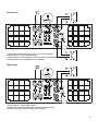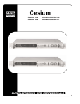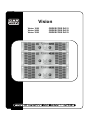
1
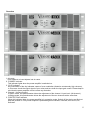
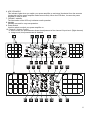
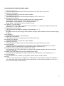
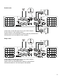
Vision
Vision 1600
Vision 2400
Vision 3500
ORDERCODE D4151
ORDERCODE D4152
ORDERCODE D4153
Congratulations!
You have bought a great, innovative product from DAP Audio.
The DAP Audio Vision series bring excitement to any venue. Whether you want simple plug-&-play action or
a sophisticated show, this product provides the effect you need.
You can rely on DAP Audio, for more excellent audio products.
We design and manufacture professional audio equipment for the entertainment industry.
New products are being launched regularly. We work hard to keep you, our customer, satisfied.
You can get some of the best quality, best priced products on the market from DAP Audio.
So next time, turn to DAP Audio for more great audio equipment.
Always get the best -- with DAP Audio !
Thank you!
DAP Audio
DAP Audio Vision 1600, 2400, 3500 Product Guide
Warning..…...................................................................................………………………………………….. 2
Safety-instructions………………………………………………………………………………………….…. 2
Operating Determinations……………………………………………………………………………………. 3
Description..…..............................................................................……….…………………………………
Features………………………………………………………………………………….………………….….
Overview Front side..…………………………………………………………………………………....……
Overview Back side..…………………………………………………………………………………….……
4
4
4
5
Installation..................................................................……………………………..…………………………
7
Set Up and Operation.....................................................................……..…………………………….…… 7
Connecting VISION 1600…………………..………………………………………………………..….……. 8
Connecting VISION 2400 & 3500..………………….…………………………………………………....…. 10
Maintenance………..............................….......................................………..………….…….………….….. 12
Troubleshooting………..............................…................................………..………….…….………….….. 12
Product Specifications.................................................................……………….…….………………….
13
1
WARNING
CAUTION!
Keep this system away from rain and moisture!
FOR YOUR OWN SAFETY, PLEASE READ THIS USER MANUAL CAREFULLY
BEFORE YOUR INITIAL START-UP!
SAFETY INSTRUCTIONS
Every person involved with the installation, operation and maintenance of this system have to:
be qualified
follow the instructions of this manual
CAUTION! Be careful with your operations.
With a dangerous voltage you can suffer
a dangerous electric shock when touching the wires!
Before you initial start-up, please make sure that there is no damage caused by transportation. Should there
be any, consult your dealer and do not use the system.
To maintain perfect condition and to ensure a safe operat ion, it is absolutely necessary for the user to follow
the safety instructions and warning notes written in this manual.
Please consider that damages caused by manual modifications to the system are not subject to warranty.
This system contains no user-serviceable parts. Refer servicing to qualified technicians only.
IMPORTANT:
The manufacturer will not accept liability for any resulting damages caused by the non-observance of
this manual or any unauthorized modification to the system.
•
•
•
•
•
•
•
•
•
•
•
•
•
•
•
Never let the power-cord come into contact with other cables! Handle the power-cord and all
connections with the mains with particular caution!
Never remove warning or informative labels from the unit.
Never use anything to cover the ground contact.
Do not insert objects into air vents.
Do not connect this system to a dimmerpack.
Do not switch the system on and off in short intervals, as this would reduce the system’s life.
Do not open this device. Risk: hazardous radiation exposure.
Only use system indoor, avoid contact with water or other liquids.
Avoid flames and do not put close to flammable liquids or gases.
Always disconnect power from the mains, when system is not used. Only handle the power-cord by
the plug. Never pull out the plug by tugging the power-cord.
Make sure you don’t use the wrong kind of cables or defective cables.
Make sure that the signals into the mixer are balanced, otherwise hum could be created.
Make sure you use DI boxes to balance unbalanced signals; All incoming signals should be clear.
Make sure that the available voltage is not higher than stated on the rear panel.
Make sure that the power-cord is never crimped or damaged. Check the system and the power-cord
from time to time.
2
•
•
•
•
•
•
•
•
•
•
•
•
•
•
Always operate the unit with the AC ground wire connected to the electrical system ground.
Connecting amplifier outputs to oscilloscopes or other test equipment, while the amplifier is in
bridged mode, may damage both the amplifier and test equipment.
Do not drive the inputs with a signal level bigger, than required to drive the equipment to full output.
In system setup, the amplifier's output power must be 50%-100% more than the loaded
loudspeakers rated power.
Please turn off the power switch, when changing the power cord or signal cable, or select the input
mode switch.
In typical use, Please set the volume to 0dB position.
Sometimes, when you want to send one signal to more than one amplifier, you should use a signal
distributor.
For replacement use fuses of same type and rating only.
Prevent distortion! Make sure that all components connected to the Vision have sufficient power
ratings. Otherwise distortion will be generated because the components are operated at their limits.
Avoid ground loops! Always be sure to connect the power amps and the mixing console to the same
electrical circuit to ensure the same phase!
If system is dropped or struck, disconnect mains power supply immediately. Have a qualified
engineer inspect for safety before operating.
If the system has been exposed to drastic temperature fluctuation (e.g. after transportation), do not
switch it on immediately. The arising condensation water might damage your system. Leave the
system switched off until it has reached room temperature.
Repairs, servicing and electric connection must be carried out by a qualified technician.
WARRANTY: Till one year after date of purchase.
OPERATING DETERMINATIONS
If this system is operated in any other way, than the one described in this manual, the product may suffer
damages and the warranty becomes void.
Any other operation may lead to dangers like short-circuit, burns, electric shock, etc.
You endanger your own safety and the safety of others!
Improper installation can cause serious damage to people and property !
3
Description of the device
Features
The Vision 1600, 2400 and 3500 are professional high-end amplifiers :
Vision 1600
• 2x Channel in and Link out
• 2x Speakon out
• Built-in Clip Limiter
• Switch-able entrance sensitivity: 0.77V, 1V and 1.4V
• Bridge, parallel or stereo mode
• 30 Hz Hi-pass filter, -3 dB, 18 dB/oct.
• Ground-selector
• Back to front airflow
• Amplifier has softstart and separate standby power. In case of temporary power failure, the amplifier has to
be restarted by pushing the ON/OFF switch again. On and off switching eventually happens with relay.
Vision 2400
• This amplifier has been primarily secured on 18A
• 2x Channel in and Link out
• 2x Speakon out and 1x Speakon bridge out
• Switch-able Clip Limiter
• Switch-able entrance sensitivity: 0.77V, 1V and 1.4V
• Bridge, parallel or stereo mode
• 30 Hz Hi-pass filter, -3 dB, 18 dB/oct.
• Ground-selector
• Switch-able crossover, Low-pass, 150 Hz, 18 dB/oct.
• Back to front airflow
• Amplifier has softstart and separate standby power. In case of temporary power failure, the amplifier has to
be restarted by pushing the ON/OFF switch again. On and off switching eventually happens with relay.
Vision 3500
• This amplifier has been primarily secured on 25A
• 2x Channel in and Link out
• 2x Speakon out and 1x Speakon bridge out
• Switch-able Clip Limiter
• Switch-able entrance sensitivity: 0.77V, 1V and 1.4V
• Bridge, parallel or stereo mode
• 30 Hz Hi-pass filter, -3 dB, 18 dB/oct.
• Ground-selector
• Switch-able crossover, Low-pass, 150 Hz, 18 dB/oct.
• Back to front airflow
• Amplifier has softstart and separate standby power. In case of temporary power failure, the amplifier has to
be restarted by pushing the ON/OFF switch again. On and off switching eventually happens with relay.
4
Overview
1
3
8
7
4
1
5
6
2
7
10
3
8
7
4
1
5
6
2
7
10
3
8
7
4
5
6
2
7
10
1. Air vents
Don't obstruct or insert objects into air vents.
2. "POWER" Indicator
This indicator lights when the power amplifier is switched on.
3. "CLIP" Indicator
Any illumination of the clip indicates a state of over modulation (distortion at extremely high volumes).
In this case, check the output signal of your mixer and turn down the input gain control. Please keep in
mind that the power amplifier cannot correct any distortion.
4. Channel 1 Volume Control
In stereo mode, this potentiometer allows the adjustment of the channel 1 input level. (left channel ).
In Bridge mode, this potentiometer allows the adjustment of the two channels at the same time.
5. "PROTECTION" Indicator
When this indicator lights, the power amplifier is in protection mode. Switch off the device and find out
what the problem is. The power amplifier is protected against overheat, overload, short circuit, DC,
Soft-start.
5
6. LED "STAND BY”
This indicator lights when you switch your power amplifier on and stays illuminated for a few seconds
(during this time the power amplifier makes an auto-test). When the LED dims, it means the power
Amplifier is ready to work.
7. "SIGNAL" Indicator
The illumination of the LED only indicates a safe operation.
8. Handles
Handles are used for easy transportation.
9. Power Switch
Use this switch to switch your power amplifier on.
10. Channel 2 Volume Control
In stereo mode, this potentiometer allows the adjustment of the channel 2 input level. (Right channel)
In bridge mode, this potentiometer is disabled.
6
VISION SERIES DESCRIPTION REAR PANEL:
11. Channel 1 XLR Input
This XLR input is a balanced input. Connect this input to the left output of your mixer.
12. Channel 1 Link Socket
This balanced socket is used to link another amplifier.
13. Input Sensitivity Selector
This selector allows you, to choose the input sensitivity: 0.77V, 1.0V or 1.4V.
14. Operation Mode Selector
This switch is used to choose the operating mode of the power amplifier:
Stereo Mode: 2 inputs (channel 1 and 2) and 2 outputs are used.
Parallel Mode: 1 input (channel 1) and 2 outputs are used.
Bridge Mode: 1 input (channel 1) and 1 output are used.
15. Channel 1 Turn lock Output
Connect this turn lock output to a speaker. The branching is +1, -1 (except in bridge mode where the
branching is +1, +2 for Vision 1600).
16. Channel 2 Turn Lock Output
Connect this turn lock output to a speaker. The branching is +1, -1.
17. AC Cord
Plug this cord into the power supply socket. (Before using the power amplifier, check if the power supply
is 240V).
18. Air Entrance
This part is the air entrance. Don't obstruct it.
19. High Pass Filter Selector
This switch is used to cut low frequency under 30Hz (infrasound).
20. Channel 2 Link Socket
This balanced socket is used to link another amplifier.
21. Channel 2 XLR Input
This XLR input is a balanced input. Connect this input to the right output of your mixer.
22. Limiter Selector
This switch is used to limit input level. This function can be used to avoid damage for your power
Amplifier, if there is a malfunction in the input device (mixer, CD player, etc.).
23. Crossover Selector (Only for Vision 2400 & Vision 3500)
Put the switch in the "ON" position when you want to use the power amplifier with one (or several)
subwoofer speakers.
24. Bridge Turn Lock Output (Only for Vision 2400 & Vision 3500)
This output is the bridge output in bridge mode (see connection page 11). The branching is +1, -1.
25. Ground Selector
If you experience hum or noise in your speaker, put the selector in "ON" position.
26. Fuse
The fuse is used to protect your amplifier from different kinds of AC problems. If the power amplifier is
"on" and nothing lights, please check the fuse compartment. If fuse is broken, please be sure to use a
fuse of the same type and specification
7
Installation
Remove all packing materials from the Vision. Check that all foam and plastic padding is removed.
Screw the equipment into a 19" rack. Connect all cables.
Always disconnect from electric mains power supply before cleaning or servicing.
Damages caused by non-observance are not subject to warranty.
Set Up and Operation
Before plugging the unit in, always make sure that the power supply matches the product specification
voltage. Do not attempt to operate a 120V specification product on 240V power, or vice versa.
Install this device on a flat surface, not bending or curved.
Do not supply power before all components of the system are set up and connected properly.
You can connect the vision in 3 different modes: Stereo, Parallel and Bridged
CONNECTING FOR VISION 1600 :
Stereo mode:
In this mode, connect the 2 inputs CH1 and CH2 to your mixer's outputs.
Put the selector to the stereo position.
Output volume can be adjusted by means of the two potentiometers.
Connect the 2 turn lock outputs to the 2 speakers.
8
Parallel mode:
In this mode, connect the input CH1 to your mixer's outputs.
Put the selector on the parallel position.
Outputs volume can be adjusted by means of the two potentiometers.
Connect the 2 turn lock outputs to the 2 speakers.
Bridge mode:
In this mode, connect the input CH1 to your mixer's outputs.
Put the selector on the bridge position.
Output volume can be adjusted with channel 1 potentiometer.
Connect the channel 1 turn lock output to the speaker.
9
CONNECTING FOR VISION 2400, 3500 :
Stereo mode:
In this mode, connect the 2 inputs CH1 and CH2 to your mixer's outputs.
Put the selector on the stereo position.
Output volume can be adjusted by means of the two potentiometers.
Connect the 2 turn lock outputs to the 2 speakers.
10
Parallel mode:
In this mode, connect the input CH1 to your mixer's outputs.
Put the selector on the parallel position.
Outputs volume can be adjusted by means of the two potentiometers.
Connect the 2 turn lock outputs to the 2 speakers.
Bridge mode:
In this mode, connect the input CH1 to your mixer's outputs.
Put the selector on the bridge position.
Output volume can be adjusted with channel 1 potentiometer.
Connect the bridge turn lock output to the speaker.
11
Maintenance
The Vision requires almost no maintenance. However, you should keep the unit clean. Disconnect the
mains power supply, and then wipe the cover with a damp cloth. Do not immerse in liquid.
Keep connections clean. Disconnect electric power, and then wipe the audio connections with a damp cloth.
Make sure connections are thoroughly dry before linking equipment or supplying electric power.
Replacing a Fuse
Power surges, short-circuit or inappropriate electrical power supply may cause a fuse to burn out. If the fuse
burns out, the product will not function whatsoever. If this happens, follow the directions below to do so.
1. Unplug the unit from electric power source.
2. Insert a screwdriver into the slot in the fuse cover. Turn the screwdriver to the left, at the same time gently
push a bit (Turn and Push). The fuse will come out.
3. Remove the broken fuse. If brown or unclear, it is burned out.
4. Insert the replacement fuse into the holder where the old fuse was. Reinsert the fuse cover.
Be sure to use a fuse of the same type and specification. See the product specification label for details.
Troubleshooting
Dap Audio Vision 1600, 2400 and 3500
This troubleshooting guide is meant to help solve simple problems.
If a problem occurs, carry out the steps below in sequence until a solution is found. Once the unit operates
properly, do not carry out following steps.
If the amplifier does not operate properly, refer servicing to a technician.
1. If you experience low output or no output at all, unplug immediately.
2. Check the fuse, power from the wall, all cables etc.
3. If all of the above appears to be O.K., plug the unit in again.
4. If you are unable to determine the cause of the problem, do not open the amplifier, as this may damage
the unit and the warranty will become void.
5. Return the amplifier to your Dap Audio dealer.
12
Product Specifications
MODE
8ohm Stereo Power
4ohm Stereo Power
8ohm Bridge Power
Freq. Resp
(+0/ 0.3,1W/8ohm)
THD+N
Slew Ratio
DAMPING Factor
S/N Ratio
Input sensitivity
Input imped.(bal/unbal.)
Protection
Voltage
Crosstalk
Gross Weight
Dimensions (mm)
VISION 1600
520W
780W
1560W
20Hz-20KHz,
-3dB@100KHz
<0.03%
30V/us
400
>95dB
VISION 2400
VISION 3500
800W
1000W
1200W
1500W
2400W
3000W
20Hz-20KHz(+0/-0.5dB)
<0.03%
<0.03%
40V/us
44V/us
300
300
>95dB
>95dB
0.775V, 1V, 1.4V
20KW /10KW
overheat, short circuits, DC, limit and softstart, Output
Relay-Zero Current
Switch, Intellectual Clip Limiter.
AC 240V-50Hz (CE)
>70dB
>70dB
>70dB
27KG
44KG
47KG
590x570x150
650x585x220 (LxWxH)
(LxWxH)
Design and product specifications are subject to change without prior notice.
13
2003 Dap Audio.