1
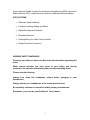
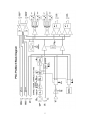
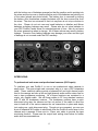
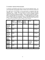
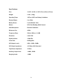
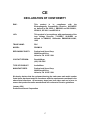
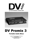
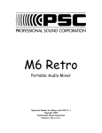
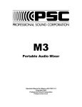
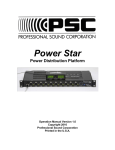
ProMix 6
Audio Mixer
Operational Manual
For PCB Version 1.7
Copyright 2007
Table of Contents
Page
Overview
2
Applications
3
Hearing Safety Warnings
3
Construction
4
Block Diagram
5
Input Panel View
6
Pre-Amplifiers
6
Gain Settings
6
Microphone Powering
7
Dedicated Line Outputs
7
Headphone Outputs
7
Front Panel View
8
Channel Fader
8
High Pass Filters
8
Channel Assignment Switch
8
Pre-Fade Listen Switch
8
Peak Reading Meters
9
Power Switch
9
Slate Microphone
10
Reference Oscillator
10
Limiters
10
Headphone Selection
10
1
Table of Contents Continued
Page
Headphone Volume
11
Right Side Panel View
11
Main XLR Outputs
11
Auxiliary Outputs
12
Ganging Connection
12
External Power Connection
12
Tape Returns
13
Battery Door
13
Interfacing
14
RoHS
15
Warranty
16
Specifications
17
CE Mark
18
Overview:
Thank you for purchasing the Professional Sound Corporation ProMix 6 portable
audio mixer. We are confident that you will find this mixer has set new standards
in mixer technologies and features at an affordable price. If you have any
questions, comments, or suggestions about this mixer or any other PSC product,
please do not hesitate to call or e-mail us. Additionally, we invite you to share
your suggestions for new products you would like to see developed.
Professional Sound Corporation extends a one-year warranty on parts and labor
to all ProMix 6 owners who return their warranty cards at the time of purchase.
This warranty gives you specific legal rights, which are stated on the warranty
card, and enables us to keep you informed of product updates.
The PSC ProMix 6 provides all of the functions necessary to produce studio
quality recordings in the field. It’s user friendly features, rugged design and sonic
2
purity make the ProMix 6 perfect for electronic news gathering (ENG), electronics
field production (EFP), reality television production and feature film production.
APPLICATIONS:
•
Electronic News Gathering
•
Location recording (Dialog and Music)
•
Digital Recoding and Playback
•
Broadcast Remotes
•
Desktop Mixing for Video Post Production
•
Reality Television Production
HEARING SAFETY WARNINGS:
Please be sure that you have read this entire manual before operating this
mixer.
While special attention has been given to your safety and hearing
protection, the operator determines proper and safe operating levels.
Please note the following:
Always turn down the headphone volume before plugging in your
headphones.
Always operate your headphones at the lowest practical level.
Be especially cautious in unknown or widely varying environments.
Remember, your ears are your livelihood! Turn it down!
3
Construction
Chassis:
The ProMix 6 chassis has been designed for maximum tensional rigidity. This
increased rigidity provides a stable base for the mixer’s modern electronics. The
complete chassis is formed from 0.040” and 0.050” aircraft aluminum. All
punching is done on a computer controlled Trump rotary turret punch press for
extreme accuracy. In addition, through careful design, we have managed to
keep the overall weight of the PSC ProMix 6 down to less than 4 lbs (1.8Kg)
The mixer’s sheet metal is then hand formed using a computer controlled six axis
Cincinnati press brake. Threaded inserts are then pressed permanently into
place and mixer cases are then painted.
Electronic Topology:
The new PSC ProMix 6 audio mixer was designed from a clean sheet of paper.
It utilizes new circuitry designed using the latest advances in semi-conductor
technology for improved performance and to further reduce the size and weight
of the product. The ProMix 6 uses proprietary pre-amplifier designs that are the
result of many hours spent testing and tweaking the input circuitry. We believe
that you will find these pre-amplifiers to be very quiet. In addition, the ProMix 6
also uses our exclusive, super high quality output transformers.
These
transformers are made to our specifications and custom built for our use. They
are hands down the largest, dual isolated output transformers used in any ENG
style mixer. We use them in our flagship AlphaMix as well.
Future Environmental Outlook:
The PSC ProMix 6 is fully RoHS compliant. It is built using lead free parts and
lead free solder. This is the first ENG style mixer to be built specifically to meet
the tough demands of the European Union’s RoHS standards. PSC is committed
to keeping our environment safe and clean for future generations.
Environmental Operation:
Your new PSC ProMix 6 audio mixer has been designed to operate under
extreme field conditions. The electronics have been designed to operate over a
temperature range of -4 to +158 degrees Fahrenheit (-20 to +70C) less the
effects on the batteries. This is in addition to the ProMix 6’s ability to operate in
high humidity conditions and makes it perfect for harsh field conditions.
4
5
Input Panel View
Pre-Amplifiers
The inputs of the PSC ProMix 6 are all female XLR connectors and the input
circuitry is balanced. Careful attention was given to RF immunity for the input
circuitry to help eliminate RF problems in the field. The XLR connectors are
wired as follows: Pin 1 = Ground, Pin 2 = High (Audio in Phase), Pin 3 Low
(Audio out of Phase)
Gain Settings
The six input channels of the PSC ProMix 6 use pre-amplifiers that are designed
for real-world ease of use. These pre-amplifiers have 3 basic gain settings.
These gain settings are labeled: C (Condenser Microphone) L (Line Level Input)
and D (Dynamic Microphone) Using these 3 settings makes for easy and fast
setups in the field. You must simply select the gain setting that best matches
your input signal and you are done. Typically, Condenser microphones (powered
microphones) have a higher output level than that of a dynamic microphone. To
use a condenser microphone, just set the input gain setting switch to “C”. To use
a dynamic microphone, set the input gain switch to “D” When using line level
sources, set the input gain setting switch to “L” When using most wireless
microphone receivers, set the input gain setting switch to “C”.
Microphone Powering
The PSC ProMix 6 audio mixer is equipped with 48PH microphone power. Each
of the six input channels has a separate switch to enable the 48PH microphone
power for that individual channel. These switches are labeled “D” and “48”. In
the “D” position, there is no microphone power being applied to that XLR input.
6
In the “48” position, 48 Phantom microphone power is being applied to that input
XLR connector. Please note that you should only use the “48” setting when
powering microphones that are designed to operate from 48PH power. If you
want to power up older Sennheiser “T” power microphones, you will need to use
a PSC 48PH to 12T adapter barrel (part # FPSC0010A, available from any PSC
dealer). Please also note that 48PH is not needed or compatible with most
wireless receivers.
If using wireless, turn that input’s microphone
powering switch to “D”.
Dedicated Line Outputs
Each of the six inputs found on the PSC ProMix 6 audio mixer are equipped with
individual line outputs. These line outputs feed pre-fader audio from the
corresponding input. They feature a ¼” line output jack operating at a nominal
level of -10dBv. These six outputs are un-balanced and are wired as follows:
Tip = audio signal, Ring = unused, Sleeve = Ground. These outputs can be used
for IFB feeds, individual camera feeds and for wireless transmission hops.
Headphone Outputs
The PSC ProMix 6 is equipped with two headphone jacks. These two jacks are
wired in parallel. One is a standard ¼” stereo jack and the second connector is a
3.5mm Mini stereo jack. Either jack may be used to drive headphones with any
impedance from 25 ohms to 600 ohms.
Front Panel View
Channel Fader
The PSC ProMix 6 audio mixer has six fader pots located across the front panel.
Each one of these fader pots controls the audio level of its corresponding input.
Rotating the fader pot clockwise increases audio level. Rotating the fader pot
counter-clockwise decreases the audio level.
7
High Pass Filters
The ProMix 6 is equipped with 3 way switch-able high pass filters on each of the
six input channels. These filters can be activated by switching the appropriate
front panel mounted switches. The switches are labeled as follows: 80, 20, 140.
These numbers represent the cut off frequencies of the high pass filters. In the
“20” position, the frequency response is flat down to 20Hz. In the “80” position,
the low frequencies are rolled off with a -3dB point of 80Hz. In the “140” position,
low frequencies are rolled of with a -3dB point of 140Hz. The “80hz” setting is
used for basic low frequency roll offs such as operating indoors with airconditioning on or outdoors in light wind conditions. The 140Hz position provides
more severe low frequency roll off and is used in high wind conditions.
Channel Assignment Switch
Each of the six input channels has a Channel Assignment switch that is located
on the front panel above the channel fader pot. These switches are used to
route the audio signal from each individual input to the appropriate output bus.
The switches are labeled as follows: L, C, and R. When set to “L”, the signal is
routed to just the left output bus. When set to “C” (Center) the signal is routed to
both the left and right output busses. When set to “R” the signal is routed to just
the right output bus.
Pre-Fade Listen Switch
Each input channel of the PSC ProMix 6 is equipped with a Pre-fade Listen
switch. These push button switches are used whenever you wish to individually
monitor that input’s audio via your headphones without having to open the fader.
By pressing the momentary button down, your headphones will automatically be
switched to monitor just that input channel. As soon as you release the PFL
button, your headphones go back to monitoring your standard headphone
selection. These PFL switches are labeled “PFL” and are located below the
channel faders. They are very useful for setting up wireless, checking for
wireless dropouts, and previewing performer audio levels without having to open
up a channel fader. In this manner, you can check on a given input without
disturbing your ongoing recording.
Peak Reading Meters
The ProMix 6 is equipped with peak reading LED meters. These meters use
high brightness LEDs for easy reading even in bright outdoor conditions. In
addition, there is a screw driver trim pot control located just below the meters that
allows for adjustment of meter brightness. These meters read and respond to
the peak level of the audio signal. They are useful when recording to today’s
digital formats. The LEDs are multi colored to allow quick visual checking of the
meter levels. The LEDs that represent audio levels of -21dB to -3dB are GREEN
8
in color. The LEDs that represent “0dB” are YELLOW in color and the LEDs that
represent +3dB or greater are RED in color. Thus you can just give a quick
glance to the meters and determine if your audio levels are too high by noting the
color present.
Power Switch
On the lower right hand corner of the front panel is the main power switch. This
switch controls all of the power used to operate the ProMix 6 audio mixer. This
switch is labeled “PWR” and is a three position switch. In the left most setting,
the switch is labeled “EXT” and this refers to external power. The mixer will
operate when the switch is set to EXT and it is connected to an external power
source such as an AC wall supply or external battery. In the center position, the
mixer is turned off. In the right most position marked “BATT” the mixer will
operate from its internal batteries. Whenever the mixer is turned on, the first
LED in each row of meter LEDs will light up Blue. This indicates proper
operating voltage is present in the internal batteries or the external power source.
When the batteries get low, these two blue LEDs will begin blinking. This
blinking condition indicates that the batteries useful life is nearly over and you
should stop and change your batteries soon. Actual remaining battery life is
dependent upon use of the mixer, number of powered condenser microphones
being used etc. You can typically expect 15 to 20 minutes of remaining run time
once the blue LEDs begin blinking.
Slate Microphone
The PSC ProMix 6 audio mixer is equipped with an internal slate microphone.
This slate microphone is used to provide on tape, voice slating of scène and take
notes, editing notes and other voice notes for future use. To operate the slate
microphone, simply press the “Slate Mic” button. This button is momentary and
thus the slate microphone will only activate for as long as you press the button.
There is also a slate microphone volume level trim pot located just to the left of
the slate mic button.
Reference Oscillator
The ProMix 6 audio mixer is equipped with a reference tone oscillator that is
used to provide a reference tone level for production editing. This tone oscillator
puts out a 440Hz tone at 0dB on the meters. At the beginning of each tape or at
the first use of any other audio storage format, you should record a 15 to 20
second burst of reference tone. This tone will be used later in post production to
set proper audio levels for subsequent transfers and is used to keep audio levels
consistent among multiple cameras.
9
Limiters
The ProMix 6 audio mixer is equipped with switchable output limiters. The
control switch for these limiters is located on the right hand side of the front panel
between the tape return monitor switch and the power switch. The output limiter
switch is labeled “LIM” and is a three-way switch. The three choices are labeled
“Off” , “S” , and “G” In the “off” position the limiters are turned off and no output
signal limiting occurs. In the “S” (separate) position, the two limiters act
independently of each other. This position is used most often when you have an
interviewer panned to one output and the interviewee panned to the other output.
This type of recoding is called split tracks and you should use the limiters in their
“S” mode for this type of work. In the “G” (ganged) position, the limiters are
ganged together and will track one another. If a high level signal on either limiter
input causes one of the limiters to activate, both limiters will activate. This type of
limiting is normally used when recording stereo signals. By keeping the limiters
ganged together, the overall stereo image will not appear to shift when limiting
occurs. It is highly recommended that you use the output limiters at all times.
This will serve to protect your recording from unexpected audio peaks that would
otherwise overload your recorder and ruin the sound quality of your recordings.
In most ENG situations, split tracks are used and thus the “S” setting on the
limiter switch is employed.
Headphone Selection
On the right side of the front panel there is a rotary switch that is used to control
what you monitor on your headphone outputs. This switch has four positions that
are marked as follows: “S”, “L”, “R”, and “M” These settings are abbreviations
for Stereo, Left, Right, and Mono. In the “Stereo” setting, the headphones are
fed a normal stereo signal. The left headphone is fed a signal from the left output
and the right headphone is fed a signal from the right output. When the switch is
set to “Left”, both drivers of your headphones are fed a signal from the left output.
When this switch is set to “Right” both drivers of your headphones are fed a
signal from the right output. When set to “Mono” both headphone drivers are fed
a signal that is a mono sum of both the left and right outputs.
Headphone Volume
Located directly above the headphone selection switch is a headphone volume
control pot. This pot raises or lowers the volume of the audio signal going to your
headphones. Turning the pot counterclockwise will lower the volume. Turning
the pot clockwise will raise the volume of the headphones. Turning the pot fully
counterclockwise will turn off the headphone volume completely. Please note the
headphone volume safety warnings at the beginning of this manual. Operating
this mixer with too high of a headphone volume setting may cause permanent
hearing damage. You are fully responsible for your own hearing protection
when using this mixer as we do not have control over your operating
10
environment, headphone type and use, operating levels, microphone type,
etc. Remember, your ears are your livelihood, Turn it Down! Please also
note to turn down the headphone volume each time before you plug in your
headphones.
Right Side Panel View
Main XLR Outputs
The ProMix 6 contains two independent sets of XLR outputs. These are located
on the right hand side panel of the mixer. They are labeled as “Camera A” Left
and Right and “Camera B” Left and Right. These XLR outputs provide balanced
audio feeds at various audio levels. Below each XLR connector is a three way
toggle switch to control the output level. These switch settings have labels of “0”,
“-10”, and “-50”. When any of these switches is set to “0”, the nominal audio
output level is 0dBV. When set to “-10”, the nominal audio output level is -10dBv
and when set to “-50” the nominal audio output level is -50dBv. These audio
signal levels correspond to the following: 0dBv corresponds to professional line
level, -10dBv corresponds to consumer line level and -50dBv corresponds to
microphone level. The two sets of XLR outputs are isolated from each other
using our proprietary dual isolated output transformers.
Auxiliary Outputs
On the right hand side panel of the ProMix 6 audio mixer are two jacks labeled as
“Aux 1” and “Aux 2”. These are the two auxiliary audio outputs. They are both
¼” stereo signal jacks. Pin outs are as follows: Tip = Left signal, Ring = Right
signal, Sleeve = Ground. Both of these auxiliary audio outputs have two-way
level selection switches located directly below each output jack. These switches
allow the signal to be sent out at either -10dBV (consumer line level) or -50dBv
(microphone level).
These auxiliary outputs can be used to drive IFB
transmitters, transcription recorders and other devices. They can also be used to
feed the ganging input connector of another ProMix 6.
11
Ganging Connection
The PSC ProMix 6 also is equipped with a “Gang Input” connector. This
connector allows the user to have access to the left and right mix busses within
the mixer. This connector can be used for connecting other mixers and audio
sources into the ProMix 6. Typically, another mixer’s output would be connected
into the ProMix 6’s ganging input to allow a greater number of input channels to
be routed through the ProMix 6. To gang two ProMix 6’s together, you must
simply connect a cable that has a ¼” stereo connector on each end from one of
the ProMix 6’s (slave unit) auxiliary outputs to the other ProMix 6’s (master unit)
ganging input. The master unit will now allow you to meter, monitor and output
all 12 of the inputs of the two mixers.
External Power Connection
On the upper right corner of the right hand side panel of the ProMix 6 audio mixer
you will find a 4 pin Hirose connector labeled as “EXT PWR” This connector is
used to connect an external source of power to operate the ProMix 6. This
connector uses industry standard pin-outs of Pin 1 = Ground and Pin 4 = Positive
power. Any external source of DC power may be used as long as it is within the
range of 7 to 18Vdc. All external sources should be externally fused for
protection. Any external power supply should also be rated to provide a
minimum of 300mA for proper operation. Internally the mixer is protected against
reversed polarity. If you incorrectly provide the external power connector with the
wrong polarity, the mixer will not be damaged, it simply will not power up.
Tape Returns
Your new PSC ProMix 6 is designed to be operated with up to two cameras.
Because of this, the ProMix 6 has two sets of tape return monitor inputs. These
are normally used with the corresponding two camera outputs. The two tape
returns are located on the right hand side panel along the top edge directly above
the XLR outputs. These two jacks are 3.5mm stereo mini jacks. Normally you
would connect the tape return plug(s) from one or two of our PSC Beta snake
cables to these jacks. The use of these jacks allows the operator to monitor the
tape return signal from his cameras, thus insuring a proper connection to the
camera and/or that proper recording has taken place depending on the camera
model. Adjacent to the jacks there are screw driver trim pots for easy level
adjustment and matching. These are used to set proper audio levels so that
when you switch from monitoring audio from the mixer to monitoring audio form
the tape returns, you have the same consistent levels throughout.
Battery Door / Battery Compartment
The battery compartment is located on the right hand side panel of the mixer.
The PSC ProMix 6 uses 8 AA alkaline or Lithium batteries. They are inserted
12
with the bottom row of batteries arranged so that the positive end is pointing into
the mixer and the top row so that the positive end of the batteries are pointing out
of the mixer (please see photo below). The battery door is removed by turning
the battery door thumbscrew counter-clockwise until the door comes free from
the mixer. The door is a universal fit, that is to say there is not a top or bottom to
the door. Please do not mix new and used batteries or alkaline and lithium
batteries as battery leakage may result. Please also do not store batteries in
your PSC ProMix 6 audio mixer for extended periods of time. Also do not leave
the mixer powered up when in storage. All of these actions may result in battery
leakage. Corrosion from leaking batteries may damage your mixer and this type
of damage is not covered under the PSC warranty.
INTERFACING:
To professional and some semi-professional cameras (XLR Inputs)
To interface your new ProMix 6 to one or two professional video cameras is
easily done. The most simple and convenient way is to use a PSC betasnake
cable. These umbilical cables provide a balanced left and right channel audio
feed to the camera and also a left and right channel audio monitor return line for
use in tape confidence monitoring. All of these functions are contained in a
single, very flexible cable. We sell these cables in 25’ long standard versions
and 15’ and 25’ breakaway versions. The breakaway versions have a quick
disconnect plug near the camera end fan out portion of the cable to allow the
user to leave all of the various camera fan out connections in place and simply
just unplug one, quick disconnect plug. Though not as convenient, you can use
a pair of standard XLR cables to send audio from the ProMix 6 audio mixer to the
camera and a separate 3.5mm mini to 3.5mm mini cable to provide the tape
monitoring function. Please see the output level setting chart below for further
audio level recommendations:
13
To consumer cameras (3.5mm input jack)
To interface your ProMix 6 audio mixer to most consumer cameras is easy. You
must simply have the appropriate cable to interface the two devices and then set
the output level of the ProMix 6 to the correct level to correspond with your
camera’s input. In most cases the camera will only be able to work with
microphone level. (-50dB) You may use one of the two available auxiliary
outputs to feed most consumer cameras. These auxiliary outputs are stereo ¼”
jacks on the right hand side of the ProMix 6. You must simply set the audio level
for the auxiliary output you are going to use to –50dB and then plug in a cable
with a ¼” stereo connector into this jack. The other end of the cable should have
a 3.5mm stereo mini plug to be able to plug it into your camera.
DEVICE:
PRO AUDIO
RECORDERS
WITH XLR
LINE LEVEL
INPUTS
PRO AUDIO
RECORDERS
WITH XLR MIC
LEVEL
INPUTS
PRO
CAMERAS
WITH XLR
LINE LEVEL
INPUTS
PRO
CAMERAS
WITH XLR MIC
LEVEL
INPUTS
SEMI PRO
CAMERAS
WITH XLR
INPUTS (PD –
150, ETC)
SEMI PRO
CAMERAS
WITH XLR
INPUTS (PD –
150, ETC)
DEVICE
PROMIX 6
PROMIX 6
INPUT
OUTPUT
OUTPUT
CONECTOR CONECTOR SWITCH
SETTING
XLR, LINE
XLR
“0”
LEVEL
SIGNAL
LEVEL
NOTES:
0dBv
Straight
XLR Cable
XLR, MIC
LEVEL
XLR
“-50”
-50dBv
Straight
XLR Cable
XLR, LINE
LEVEL
XLR
“0”
0dBv
Straight
XLR Cable
XLR, MIC
LEVEL
XLR
“-50”
-50dBv
Straight
XLR Cable
XLR, LINE
LEVEL
XLR
“-10”
Straight
XLR Cable
XLR, MIC
LEVEL
XLR
“-10dB”
-10dBv
Consumer
Line level
PD-150
-10dBv
14
Straight
XLR Cable
RoHS
This new ProMix 6 audio mixer was designed and built to meet the rigorous
standards set by the RoHS initiative of the European Union. The RoHS
(Reduction of Hazardous Substances) initiative specifies that no electronic
product may contain Lead, Mercury, Cadmium and a few other less used, but still
dangerous substances. These substances are being eliminated in order to
reduce the effects of post consumer waste on disposal sites. In other words, by
eliminating lead and other substances in the production of electronic products,
you will also eliminate them from being put into waste burial sites once they have
outlived their usefulness. By eliminating lead and other substances in waste
burial sites, you eliminate possible ground water contamination from these sites.
It’s a good long term solution to fight ground water pollution and we at PSC fully
support this plan. Several other counties are considering adopting similar
standards at the time this manual was written as is the State of California.
All Professional Sound Corporation products will meet the RoHS guidelines by
the compliance date of July 1st, 2006. Every product PSC makes that meets
these guidelines will have the following PSC symbol attached to the outer
packaging:
WARRANTY AND NON-WARRANTY SERVICE
In the unlikely event your ProMix 6 requires service, it should be carefully packed
and shipped prepaid to:
Professional Sound Corporation
Attn: Service Department
28085 Smyth Drive
Valencia, CA 91355 USA
PH 661-295-9395
FAX 661-295-8398
e-mail: [email protected]
Please call before shipping your mixer to us. We may be able to solve your
problem via the telephone. During our 20 years in business, many mixers have
been shipped into PSC for service with only incorrect switch settings etc.
Complete details of the PSC ProMix 6 mixer warranty are given on the enclosed
warranty registration card.
15
Specifications:
Size:
10.650” x 8.000: x 2.300” (27cm x 20cm x 5.8cm)
Weight:
4 Lbs (1.8Kg)
Operating Temp:
-20F to +140F Less Battery Limitations
External Power:
6 to 18Vdc
Battery Power:
8 x AA Alkaline Cells
Meters:
LED, Peak Reading, Multi-Colored
Slate Microphone:
Electrete Condenser
Reference Osc:
440Hz
Frequency Resp:
20Hz to 20Khz +/- 0.5 dB
Distortion:
0.08% THD
Signal to Noise:
128db EIN
Cross Talk:
65dB @1Khz
XLR Output Levels:
0dBv, -10dBv, -50dBv
XLR Output Impedance:
<25 Ohms, 600 Ohm rated
Tape Return Impedance:
1K Ohm
Auxiliary Output Level:
-10dBv, -50dBv
Ganging Levels:
-10dBv
16
CE
DECLARATION OF CONFORMITY
EMC:
This
product
is
in
compliance
with
the
Electromagnetic Compatibility Directive, 89/336/EEC
as defined in EN 50081-1, EN55022 and EN 50082-1,
IEC801-2, IEC 801-3 and IEC801-4.
LVD:
This product is in compliance with requirements of the
Low Voltage Directive, 73/23/EEC, 93/68/EEC as
defined in EN60065, 1993and/or EN60950/A1/A2/A3,
1995
TRADE NAME:
PSC
MODEL:
PROMIX 6
REPONSIBLE PARTY:
Professional Sound Corp
28085 Smyth Drive
Valencia, CA 91355 USA
CONTACT PERSON:
Ronald Meyer
(661) 295-9395
TYPE OF PRODUCT:
Audio Mixer
MANUFACTURER:
Professional Sound Corp
28085 Smyth Drive
Valencia, CA 91355 USA
We hereby declare that the equipment bearing the trade name and model number
listed above has been tested in accordance with the requirements contained in the
above listed directives. All necessary steps have been taken and are in force to
assure that production units manufactured will conform to Directive guidelines.
January 2006
Professional Sound Corporation
17