1
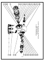
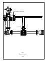
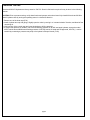
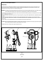
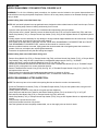
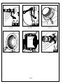
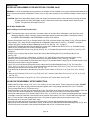
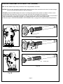
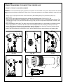
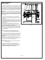
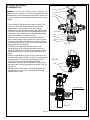
AMERICAN AVK COMPANY
AVK SERIES 2472 - HIGH PRESSURE,
WET BARREL HYDRANT
FIELD MAINTENANCE AND
INSTRUCTION MANUAL
TABLE OF CONTENTS
EXPLODED ASSEMBLY / PARTS LIST
INTRODUCTION / DESCRIPTION
RECEIVING AND STORAGE
INSTALLATION AND TESTING
- INSTALLATION
- TESTING
OPERATION AND MAINTENANCE
- HYDRANT TOOLS
- OPERATION
- MAINTENANCE PROCEDURES
- INSPECTION
- DISASSEMBLY FOR INSPECTION
- REASSEMBLY AFTER INSPECTION
REPAIR PROCEDURES
- TRAFFIC REPAIR KIT
OPTIONAL EQUIPMENT
- FLOWGUARD
TROUBLESHOOTING GUIDE
PARTS AND SERVICE
WARRANTY
American AVK Company
An ISO 9001-2000 registered company
Maintenance Manual Series 2472
*Subject to change without notice. (rev. 02/09 A)
101
109
110
111
112
113
141
139
140
137
131
132
28
120
114
139
138
American AVK Series 2472 High Pressure
Wet Barrel Hydrant
Exploded Parts Breakdown
134
142
135
136
133
114
128
129
19
115
114
122
31
page 1
Item No.
19
22
23
24*
25
28
31
101
109
110
111
112
113
114
115
116
120
122
126
128
129
131
132
133
134
135
136
137
138
139
140
141
142
Description
Hose Nozzle Cap
Hose Nozzle O-ring
Nozzle Retaining Screw
Chain Set
Pumper Nozzle O-ring
Pumper Cap
Nozzle Section Washer
Nozzle Section
Outer Stem Nut O-ring
Stem Nut
Inner Stem Nut O-ring
Dummy Nut
Dummy Nut Retaining Bolt
Nozzle/Stem/Thrust Nut Retaining Screw
Hose Nozzle Cap Gasket
Hose Nozzle
Pumper Cap Gasket
Nozzle Section Bolt
Pumper Nozzle
Threaded Hose Nozzle O-ring
Threaded Hose Nozzle
Threaded Pumper Nozzle O-ring
Threaded Pumper Nozzle
2.5" Valve Disc
2.5" Valve Stem
2.5" Thrust Nut
2.5" Thrust Collar
4.5" Valve Disc
4.5" Valve Stem
4.5" Thrust Nut
4.5" Thrust Collar
4.5" Thrust Nut O-ring
2.5" Thrust Nut O-ring
* Not Shown
page 2
Material
Grey iron, ASTM A126, "B"
NBR
304 Stainless steel
Zinc Plated steel
NBR
Grey iron, ASTM A126, "B"
Zinc Plate, 304,316 Stainless steel
Ductile Iron, ASTM A536
NBR
Copper Alloy
NBR
Grey iron, ASTM A126, "B"
304 Stainless steel
304 Stainless steel
NBR, Neoprene
Copper Alloy
NBR, Neoprene
Zinc Plate, 304,316 Stainless steel
Copper Alloy
NBR
Copper Alloy
NBR
Copper Alloy
EPDM encapsulated ductile iron
Copper Alloy
Copper Alloy
304 Stainless steel
EPDM encapsulated ductile iron
Copper Alloy
Copper Alloy
304 Stainless steel
NBR
NBR
INTRODUCTION / DESCRIPTION
The American AVK Series 24 Wet Barrel Hydrant is designed to be a trouble free, easy to maintain hydrant. This
manual will provide you with the information needed to properly install and maintain the fire hydrant and to ensure a long
service life. The series 24 Wet Barrel Hydrant is rated for a working pressure of 200 psi, is UL listed and FM approved, and
meets or exceeds the requirements of AWWA C503, Standard for Wet Barrel Fire Hydrants, (where applicable). American
AVK also provides an additional series 24 model, the 2472, that has a rated working pressure of 250 psi. that is UL listed and
FM approved, and an AWWA rated working pressure of 350 psi..
American AVK series 24 Wet Barrel Hydrants are manufactured using three major materials. Ductile iron for general
installations, 304 stainless steel for use in industrial or corrosive environments, and bronze, for coastal, or environments in or
near air containing higher salt contents. The AVK Series 24 hydrant and hydrant tools are designed so that one person can
perform all routine repairs and maintenance outlined in this manual.
RECEIVING AND STORAGE
Inspect the hydrants upon receipt for damage in shipment. Note any damage on the bill of lading and have the driver
sign it. Notify American AVK. Unload all of the hydrants carefully to avoid damage. Verify that the hydrants have the correct
direction to open, the correct nozzle configuration and threads, the correct operating nut size and shape, the correct depth
of bury, and the correct inlet connection. Hydrants should remain clean and dry, and the main valve should be closed until
installed to prevent weather related damage. For long term storage the hydrants should be stored indoors.
INSTALLATION AND TESTING
NOTE: American AVK recommends AWWA Standard C600 and AWWA Manual M17 for further information regarding hydrant installation and testing.
NOTE: Consult local codes and standards for proper fire hydrant placement and spacing
WARNING: All water lines must be isolated or depressurized and drained before installing or maintaining fire hydrants. Failure to do so may cause pressure to be released resulting in severe injury or death.
INSTALLATION
Correct installation of the Series 24 Wet Barrel Hydrant is important for proper operation. The following steps are
general installation guidelines for a standard AVK Series 24 fire hydrant. Local conditions may require variations.
1. Before installing a hydrant, check to make sure all bolts are tight and all nozzles are properly installed (See NOZZLE INSTALLATION). Clean any dirt and debris from inside the hydrant base and from the hydrant lead.
2. The Pumper Nozzle (F126) should always face the street to provide a quick connection for the Fire Department.
3. The traffic section ( Breakable Flange, (F124 ) should be set so it remains 2” above grade. The Breakable Flange also
allows 360 degree positioning of the Nozzle Section.
page 3
2' min.
Concrete collar for protection of traffic
model hydrants.
6"
2'
Curb
Bury
Concrete
Supply Valve
Concrete
thrust block
Concrete
Fig. 1
Hydrant Installation
page 4
Concrete
thrust block
PRESSURE TESTING
American AVK 2472 Hydrants are factory tested to 700 PSI. Should a field test be required it may be done in the following
manner.
CAUTION: Prior to pressure testing, verify that all outlet and pumper valves have been fully closed! All American AVK Wet
Barrel Hydrants close by turning the operating stems in a clockwise direction.
1. Remove one of the hose caps (F19).
2. Install a hydrant test cap with gauge, Slightly open the valve by turning in a “counterclockwise” direction, and bleed off the
remaining air.
3. Verify security of the nozzle caps and open the hydrant to full line pressure.
4. If a higher test pressure is needed ( max. 200 PSI working pressure for all AVK wet barrel hydrants, except the model
2472X, which has an AWWA rated working pressure of 350 PSI, and is UL listed and FM approved, 250 PSI ), it can be
reached by connecting a pressure test pump to the hydrant’s Pumper Nozzle (F126).
page 5
OPERATION AND MAINTENANCE
HYDRANT TOOLS
1. AVK Operating Wrench (Wet Barrels)
2. AVK Threaded Wet Barrel Nozzle Wrench
3. Drift Punch
4. Hammer
Part Number:
Part Number:
24-150-30-400
24-150-308-001
METRIC AND INCH WRENCH REQUIREMENTS FOR AMERICAN AVK WET BARREL HYDRANTS
PART
INCH SIZE
METRIC SIZE
Dummy Nut Retaining Bolt (Allen)
Stem Nut Retaining Screw (Allen)
Nozzle Section Bolts and Nuts
15/64”
7/64”
15/16”
6mm
N/A
24mm
AVK Threaded Wet Barrel
Nozzle Wrench
24-150-308-001
AVK Wet Barrel
Operating Wrench
24-150-30-400
page 6
OPERATION AND MAINTENANCE
OPERATION
American AVK Series 24 Wet Barrel Hydrants are factory tested and lubricated and require minimum maintenance, but
all fire hydrants should be inspected for obvious damage, opened fully and flowed, at no less than once a year. Local
maintenance services may require more frequent testing cycles.
WARNING: All hydrant hose outlet and pumper valves should be in the fully closed position while not in use. Always insure
that the Water Main Supply Valve is open after any maintenance procedure has been performed.
1. Verify that all of the hydrant outlets are fully closed. Note that all AVK Wet Barrel Hydrants are manufactured in the "Open
Left", configuration. (See Fig. 2.)
2. Remove the desired outlet Hose Cap (F19), or Pumper Cap (F28), using the AVK Hydrant Wrench or adjustable hydrant
wrench.
3. Connect the desired apparatus to the hydrant. Slowly open the desired outlet by turning the 2.5" Valve Stem (F134),
or 4.5" Valve Stem (F138) counter clockwise, using the AVK Hydrant Wrench or adjustable hydrant wrench on the Dummy
Nut (F112).
4. Turn the stem in the clockwise direction to close the desired valve and shut water flow off.
CAUTION: After the hydrant has been turned off, carefully remove the hose or apparatus and visually verify that the hydrant
valve is fully closed and no debris is preventing full valve closure.
5. Replace the Hose or Pumper Cap using the hydrant wrench.
F134
F112
F138
F28
Fig. 2
Operation
page 7
F19
INSPECTION
NOZZLE DISASSEMBLY FOR INSPECTION: FIGURES 3A-3F
WARNING: For all of the following repair procedures, the hydrant must be isolated or the system depressurized and
drained before removing the hydrant components. Failure to do so may cause pressure to be released resulting in severe
injury or death.
Nozzle leaking from around the Nozzle Cap:
NOTE: AVK wet barrel hydrants have cap gaskets that are designed to allow residual water to drain from the caps. Perform
the following steps if water is leaking continuously from a nozzle.
1. Cycle the valve open then fully closed. See if residual water stops draining from the hydrant.
2. Verify that the valve is closed. Carefully remove the Hose Nozzle Cap (F19), or Pumper Nozzle Cap (F28), and Hose
Nozzle Cap Gasket (F115), or Pumper Nozzle Cap Gasket (F120), using an AVK Hydrant Wrench or adjustable hydrant
wrench.
3. Visually inspect the valve assembly for any damage or foreign material trapped between the valve and nozzle. If foreign
material is present, open the valve and remove the material.
4. If the rubber on the Valve Disc is damaged, refer the "VALVE DISC DISASSEMBLY FOR INSPECTION" and "VALVE
DISC REASSEMBLY FOR INSPECTION", sections of this manual for corrective action.
5. When the problem has been corrected, lightly grease the nozzle threads with a food grade grease that contains no
acetate or silicone, and replace the cap and gasket assembly.
6. Pressurize the hydrant and verify that the leaking has stopped.
Nozzle leaking from around the Nozzle O-ring area:
1. Remove Hose Nozzle Cap (F19), or Pumper Nozzle Cap (F28), and Hose Nozzle Cap Gasket (F115), or Pumper Nozzle
Cap Gasket (F120), using an AVK Hydrant Wrench or adjustable hydrant wrench. See Fig. "3A,3B&3F".
2. Using a drift punch, remove the Nozzle Retaining Screw (F114). See Fig. "3C"
3. Use the AVK Threaded Wet Barrel Nozzle Wrench to remove the Threaded Hose Nozzle (F116), or Threaded Pumper
Nozzle (F126), turning them in a counter clockwise direction.
4. Remove Threaded Hose Nozzle O-ring (F128), See Fig. 3D, or Threaded Pumper Nozzle O-ring (F131), See Fig. "3E",
and replace with a new one.
5. Lightly grease the o-ring with a food grade grease that contains no acetate or silicone.
6. Follow the steps in "REASSEMBLY AFTER INSPECTION", to reinstall the nozzles and caps.
NOZZLE REASSEMBLY AFTER INSPECTION:
NOTE: The valve may have to be turned in the opening direction to allow the nozzle to be inserted fully.
1. Screw the Threaded Hose Nozzle (F129), or Threaded Pumper Nozzle (F132) into the hydrant outlet, using the AVK
Threaded Nozzle Wrench.
2. Visually inspect the outlet to verify that the o-ring has not been displaced.
3. Use a drift punch and hammer to install a new Nozzle Retaining Screw (F114), as shown in Fig. 3C or Fig.3E.
4. Re-install the Hose Nozzle Cap (F19), or Pumper Nozzle Cap (F28), and Hose
Nozzle Cap Gasket (F115), or Pumper Nozzle Cap Gasket (F120), using an AVK Hydrant Wrench or adjustable hydrant
wrench.
5. Verify that the Cap has been secured.
6. Verify that all outlets have been fully closed.
7. Once the hydrant has been completely reassembled, turn on the supply valve to check for leaks.
page 8
F19
F115
F129
F128
F114
Remove Nozzle
Retaining Screw
(F114),to allow
nozzle removal.
Fig. 3A
Fig. 3B
Fig. 3C
F28
F131
F120
F128
F132
F131
F114
F114
Fig. 3D
Fig. 3E
page 9
Fig. 3F
INSPECTION
VALVE DISC DISASSEMBLY FOR INSPECTION: FIGURES 4A-4E
WARNING: For all of the following repair procedures, the hydrant must be isolated or the system depressurized and drained
before removing the hydrant components. Failure to do so may cause pressure to be released resulting in severe injury or
death.
CAUTION: Shut off the Water Main Supply Valve and release the internal pressure to the Hydrant by removing the lowest
Pumper Nozzle Cap (F28), and slightly open the outlet valve to allow any residual water to drain from the
hydrant. The hydrant is now ready for service.
VALVE DISC INSPECTION
Nozzle leaking from around the Valve Disc:
NOTE: The following steps may be required if the rubber surface of the Valve Disc is damaged. If the Valve Disc is not
damaged, inspect the hose or pumper nozzle for damaged sealing surfaces and replace if necessary. Refer to
the NOZZLE DISASSEMBLY and REASSEMBLY sections of this manual.
1. Remove Hose Nozzle Cap (F19), or Pumper Nozzle Cap (F28), and Hose Nozzle Cap Gasket (F115), or Pumper Nozzle
Cap Gasket (F120), using an AVK Hydrant Wrench or adjustable hydrant wrench. See Fig. "3A,3B&3F", on page 9.
2. Using a drift punch, remove the Nozzle Retaining Screw (F114). See Fig. "3C", on page 9.
3. Use the AVK Threaded Wet Barrel Nozzle Wrench to remove the Threaded Hose Nozzle (F116), or Threaded Pumper
Nozzle (F126), turning them in a counter clockwise direction.
4. Remove Threaded Hose Nozzle O-ring (F128), See Fig. 3D, or Threaded Pumper Nozzle O-ring (F131), See Fig. "3E",
on page 9.
5. Using a 15/64” or (6mm) Allen wrench, remove the Dummy Nut Retaining Bolt (F113) and Dummy Nut (F112).
See Fig. "4A"
6. The Valve Stem (F134 for 2.5” Valve Stem), (F138 for 4”-4.5” Valve Stem) can now be unscrewed, (In the closing
direction.), from the Stem Nut (F110) and removed from the Nozzle Section (F101). See Figs. "4A &4B".
7. At this time, it is recommended the Inner Stem Nut O-rings (F111) and the Nozzle O-rings (F25 for Pumper Nozzle O-ring)
and (F22 for Hose Nozzle O-ring) be replaced.
8. Use a 7/64” or (3mm) Allen wrench and remove the Stem Nut/Thrust Nut Retaining Screw (F114). The Valve Disc
(F133 , for 2.5"), or (F137, for 4"-4.5"), can be removed from the Thrust Nut (F135, for 2.5") or (F139, for 4"-4.5"), by
unscrewing the valve disc from the thrust nut. See Fig. "4C"
9. Push the thrust nut towards the threads and remove the Thrust Collars, (F136 for 2.5"), or (F140 for 4"-4.5"). See Fig.
"4D"
10. Remove the Thrust Nut (F135, for 2.5") or (F139, for 4"-4.5"), from the Valve Stem (F134, for 2.5"), (F137, for 4"-4.5").
See Fig. "4D"
11. Remove the Thrust Nut O-ring (F141, for 2.5") or (F142 for 4"-4.5") valve stems. See Fig. "4E"
VALVE DISC REASSEMBLY AFTER INSPECTION:
1. Replace the Thrust Nut O-ring, (F141, for 2.5") or (F142 for 4"-4.5") valve stems. These o-rings act as a brake, DO NOT
grease the o-rings. Wipe off any grease that may have gotten on the o-ring during assembly. The 4"-4.5" Thrust Nut
O-ring is larger than the 2.5" Thrust Nut O-ring.
2. Slide the thrust nut over the stem end that has the o-ring. The threads of the thrust nut need to point toward the short end
so the valve disc can be threaded on it. Push the thrust nut over the o-ring to make room for the thrust collars.
3. Grease the inside grooves of the Thrust Collar (F136 for 2.5"), or (F140 for 4"-4.5") with a food grade grease that contains
no acetate or silicone. Install the Thrust Collar over the grooves of the stems. The 4"-4.5" Thrust Collars are larger than
the 2.5" Thrust Collars. Avoid getting grease on the o-ring. Wipe off grease that may have gotten on the o-ring.
4. Pull the thrust nut up over the collars until it stops.
5. Screw the valve disc and thrust nut together until hand tight. Then use the appropriate hand tools to tighten.
6. Apply a drop of thread-locker (Loctite #242 or equal), to the end of the Stem Nut/Thrust Nut Retaining Screw (F114), and
screw into the hole on the side of the valve disc and tighten with a 7/64” or (3mm) Allen wrench..
page 10
VALVE DISC REASSEMBLY AFTER INSPECTION: (continued):
Note: The disc should not spin freely on the stem. The o-ring should act as a brake.
CAUTION: The valve disc assemblies should be tight enough to prevent linear movement on the stem, but loose enough
that you can rotate the assembly on the stem by hand.
7. DO NOT grease the ACME threads of the stems. Put food grade grease, that contains no acetate or silicone, on the
inside threads of the Stem Nut (F110), then screw the stem/valve disc assembly into the Stem Nut.
8. Place a Dummy Nut (F112) onto the pentagon of stem and secure it with a Dummy Nut Retaining Bolt (F113) that has a
drop of thread-locker (Loctite #242 or equal), on it. Tighten the bolt with 15/64” or (6mm) Allen wrench.
9. Follow the steps in "NOZZLE REASSEMBLY AFTER INSPECTION", on page 9 to re-install the Nozzle/Cap assembly.
F133
F112 F113
F110
F114
Fig. 4C
F135
Fig. 4A
F136
Fig. 4D
F141
ACME threads
Fig. 4E
Fig. 4B
page 11
INSPECTION
STEM NUT DISASSEMBLY FOR INSPECTION: FIGURES 5A-5E
STEM NUT / STEM NUT O-RING REPLACEMENT
WARNING: For all of the following repair procedures, the hydrant must be isolated or the system depressurized and drained
before removing the hydrant components. Failure to do so may cause pressure to be released resulting in severe injury or
death.
1. Using a 15/64” or (6mm) Allen wrench, remove the Dummy Nut Retaining Bolt (F113) and Dummy Nut (F112).
See Fig. "5A"
2. Use a 7/64” or (3mm) Allen wrench and remove the Stem Nut Retaining Screw (F114). See Fig. "5B"
3. Using an AVK Hydrant Wrench or adjustable wrench, unscrew the Stem Nut (F110) in a counterclockwise direction. The
Inner Stem Nut O-rings (F111) and Outer Stem Nut O-ring (F109) can now be inspected and replaced if necessary. See
Figs. "5C&5D"
4. When re-installing the Stem Nut (F110) apply a thin coat of food grade grease or oil, that contains no acetate or silicone,
to the o-rings (F109,F111) . Also take care to avoid cross threading the Stem Nut threads in the ductile iron Nozzle
Section. Apply a drop of thread-locker (Loctite #242 or equal), to the end of the Stem Nut/Thrust Nut Retaining Screw
(F114), and tighten with a 7/64” or (3mm) Allen wrench. See Fig. "5B&5E"
5. Apply a drop of thread-locker (Loctite #242 or equal), and re-install the Dummy Nut and Dummy Nut Retaining Bolt.
F112 F113
F110
F114
Fig. 5A
Fig. 5B
Fig. 5C
F109
F110
F111
F109
Fig. 5D
Fig. 5E
page 12
F111
REPAIR PROCEDURES
TRAFFIC REPAIR:
AVK Wet Barrel Hydrants feature a safety Breakable Flange
Unit design. This allows the hydrant head assembly to be
struck by a vehicle and “Break Away” reducing the impact to
the water main. In the event the hydrant head assembly has
been broken away, the following repairs will be necessary.
F122
F123
F31
WARNING: For all of the following repair procedures, the
hydrant must be isolated or the system depressurized and
drained before removing the hydrant components. Failure to
do so may cause pressure to be released resulting in severe
injury or death.
1. Remove any mounting hardware, the old Wet Barrel
Flange O-ring (F123), broken Break Ring (F124) pieces,
and discard.
2. Place the new Wet Barrel Flange O-ring in the groove of
the Wet Barrel Flange Section (F127). Place the Hydrant
Nozzle Section Assembly on the Flange Section and
align the holes.
3. Install the Nozzle Section Bolts (F122),( with a new
Nozzle Section Washer (F31) beneath the head of each
bolt), into six mounting holes. ( See Fig. 6 )
4. Place the two halves of the Break Ring (F124) together
below the lip of the Flange Section (F127) and lift upward
until the bolts project down through the holes in the new
Break Ring halves.
F124
F31
Outer Flange
poined up
F127
F125
Fig. 6
NOTE: The cut away view of the Break Ring shows
orientation with the outer flange pointing upward.
5. Place the new Nozzle Section Washers (F31) and Nozzle
Section Nuts (F125) on the bolts, beginning with the two
overlapping holes that mate the two halves of the Break
Ring pair.
6. With a 15/16” or (24mm) wrench tighten the nuts in a
diametric pattern ( 180 degrees apart ) to apply a uniform
torque evenly around the new Break Ring.
CAUTION: Maximum torque on the nuts must not exceed
60 foot pounds.
7. Re-pressurize the hydrant slowly, bleeding off any
trapped air, to prevent air pressure from blowing out the
new gasket or water hammer from breaking the new
Break Ring or damaging the water system
page 13
OPTIONAL EQUIPMENT
FLOWGUARD II ®
F143
WARNING: For all of the following repair procedures, the
hydrant must be isolated or the system depressurized and
drained before removing the hydrant components. Failure to do
so may cause pressure to be released resulting in severe injury
or death.
1. Turn the Body (F128) up-side-down and set it down. The
cast-in flow arrow should be pointing toward the Hard
stable surface. Place the Ball (F132), into the Body.
2. Install the 8mm thick Seat Ring O-ring (F144), (the thickest
of the three o-rings in the kit) onto the stainless steel Lower
Seat Ring (F130), and grease the o-ring with a food grade
grease that contains no acetate or silicone.
3. Place the Lower Seat Ring into the body and press into
place. Ensure that the O-ring remains in it’s proper location.
4. Use food grade grease that contains no acetate or silicone,
to stick the Lower O-ring (F145), in the groove between the
Body and the Lower Seat Ring.
5. Carefully turn the assembly over and place it on the
mounting flange of the riser pipe and attach loosely with
mounting hardware. The bolts should be installed from the
bottom so that with the nuts are on top of the check valve
flange.
6. Place the Upper Retaining Cage (F129) into the top of the
assembly and install the Upper O-ring (F143) into the groove
created between the Body and Upper Retaining Cage.
7. Carefully mount the Wet barrel assembly onto the
FlowGuard II assembly with the Breakable Flange (F124)
and mount with the mounting hardware as shown in Fig. 7B
and Fig. 7C.
8. Carefully rotate the Wet barrel to the desired position. Do
not dislodge the Upper O-ring, and tighten all mounting
hardware to 60 Ft. Lbs. .
F129
F128
F124
F30,F31,F34
F132
F144
F130
F145
Fig. 7A
Fig. 7B
F124
7.5" to Bury Line
Fig. 7C
page 14
A
TROUBLESHOOTING GUIDE
PROBLEM: Hydrant leaking from around nozzle.
Probable Cause:
Damaged valve disc or nozzle sealing surface.
Corrective action:
Inspect valve disc and nozzle sealing surfaces and replace if necessary.
PROBLEM: Hydrant leaking from around stem nut.
Probable Cause:
Damaged stem o-rings.
Corrective action:
Replace stem o-rings.
PROBLEM: Nozzle section facing the wrong direction.
Corrective action:
Loosen the Nozzle Section hardware and carefully rotate the Nozzle Section to the desired
position. Tighten the mounting hardware to 60 Ft. Lbs..
PROBLEM: Hydrant flow is low.
Probable Cause:
Hydrant or supply vale is not fully open.
Corrective action:
Verify that the hydrant is fully open. The AVK Series 24 hydrant valve discs are fully opened
in approximately 9-14 turns.
Also locate and verify that the supply valve is fully open.
page 15
PARTS AND SERVICE
For information on parts and service for your area contact American AVK. Make a note of the valve model number and size
located on the valve and contact:
American AVK Company
2155 N. Meridian Blvd.
Minden, NV 89423
PH: 775-552-1400
FAX: 775-783-7502
www.americanavk.com
AMERICAN AVK COMPANY WARRANTY
SERIES 24 WET BARREL HYDRANTS
American AVK Company warrants all models of Series 24 Wet Barrel Fire Hydrants to be free from defects in workmanship
and materials for a period of ten (10) years from the date of shipment from American AVK Company. American AVK Company
shall have no obligation under this warranty unless it is notified of claims hereunder promptly and in writing upon discovery
thereof and within the warranty period, and unless the product is delivered to an American AVK Company facility within thirty
(30) days of such notice.
American AVK shall have the right to inspect said product before it is removed from installation. If the product is removed from
installation prior to approval from American AVK this warranty shall be void.
As to motors, gearing or accessory equipment purchased by American AVK Company from others manufacturers, and used
or incorporated into American AVK Company’s products, those manufacturers’ warranties shall apply.
American AVK Company will honor all reasonable costs to repair or replace any American AVK Company Wet Barrel Fire
Hydrant found to be defective.
American AVK Company's sole responsibility shall be, in its sole discretion, to replace the product with the same or a similar
product, repair the product, or refund the price paid for the product provided the product has been properly applied and used
under normal service and under conditions for which it is designed. American AVK Company shall not be liable for indirect,
special, incidental, or consequential damage or penalties and does not assume any liability of purchase to others or to anyone
for injury to persons or property.
THIS IS THE EXCLUSIVE WARRANTY GIVEN IN CONNECTION WITH THE SALE OF THIS PRODUCT. THERE ARE
NO OTHER WARRANTIES, EXPRESSED OR IMPLIED, INCLUDING EXPRESSED OR IMPLIED WARRANTY OF
MERCHANTABILITY, OR ANY EXPRESSED OR IMPLIED WARRANTY OF SUITABILITY FOR ANY PARTICULAR
PURPOSE, GIVEN BY AMERICAN AVK COMPANY IN CONNECTION WITH THIS PRODUCT.
page 16
PARTS AND SERVICE
For information on parts and service for your area contact American AVK. Make a note of the valve model number and size
located on the valve and contact:
American AVK Company
2155 N. Meridian Blvd.
Minden, NV 89423
PH: 775-552-1400
FAX: 775-783-7502
www.americanavk.com
AMERICAN AVK COMPANY WARRANTY
SERIES 2488 FlowGuard II ®
American AVK Company warrants its Series 2488 FlowGuard II to be free from defects in workmanship and materials for
a period of one (1) year from the date of shipment from American AVK Company. American AVK Company shall have no
obligation under this warranty unless it is notified of claims hereunder promptly and in writing upon discovery thereof and
within the warranty period, and unless the product is delivered to American AVK Company within thirty (30) days of such
notice.
American AVK shall have the right to inspect said product before it is removed from installation. If the product is removed from
installation prior to approval from American AVK this warranty shall be void.
As to motors, gearing or accessory equipment purchased by American AVK Company from other manufacturers, and
used or incorporated into American AVK Company’s products, those manufacturers’ warranties shall apply.
American AVK Company's sole responsibility shall be, in its sole discretion, to replace the product with the same or a similar
product, repair the product, or refund the price paid for the product provided the product has been properly applied and used
under normal service and under conditions for which it is designed. American AVK Company shall not be liable for indirect,
special, incidental, or consequential damage or penalties and does not assume any liability of purchase to others or to anyone
for injury to persons or property.
THIS IS THE EXCLUSIVE WARRANTY GIVEN IN CONNECTION WITH THE SALE OF THIS PRODUCT. THERE
ARE NO OTHER WARRANTIES, EXPRESSED OR IMPLIED, INCLUDING EXPRESSED OR IMPLIED WARRANTY
OF MERCHANTABILITY, OR ANY EXPRESSED OR IMPLIED WARRANTY OF SUITABILITY FOR ANY
PARTICULAR PURPOSE, GIVEN BY AMERICAN AVK COMPANY IN CONNECTION WITH THIS PRODUCT.
page 17
page 18