1
APPLICATION NOTE
RX62N Group
USB Basic Firmware <Short Sheet>
R01AN0495EJ0100
Rev.1.00
Apr 15, 2011
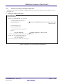
Introduction
This document is an installation guide for the Renesas USB Basic firmware (herein referred to as USB-BASIC-F/W),
a sample program for USB interface control using the USB device.
This document is intended for use with the instruction manual for the Renesas USB Basic firmware and the device data
sheet when developing software.
The USB-BASIC-F/W (Application Notes and Sample codes) are available for download from the Renesas web.
Renesas Website:
http://www.renesas.com/
Product Name:
Renesas USB Device USB Basic Firmware
File Name:
an_r01an0512ej_rx_usb.zip
Comments:
Appilcation Notes (r01an0512ej_rx62n_usb.pdf) and Sample Codes (Source Files) are included.
Target Device
RX62N
Contents
1. Introduction........................................................................................................................................ 2
1.1 Feature Overview .............................................................................................................................. 2
1.2 Preparation........................................................................................................................................ 2
2. Operating USB-BASIC-F/W Without Modifications........................................................................... 3
2.1 Sample Application Operation Confirmation ..................................................................................... 3
2.2 Confirming Operations with USBCV ................................................................................................. 7
3.
3.1
3.2
3.3
Customized USB-BASIC-F/W Operations ........................................................................................ 8
User Definitions ................................................................................................................................. 8
Use as USB peripheral function ...................................................................................................... 11
Use as USB host function ............................................................................................................... 20
4. Software Configuration.................................................................................................................... 27
4.1 List of Files ...................................................................................................................................... 31
R01AN0495EJ0100 Rev.1.00
Apr 15, 2011
Page 1 of 32
USB Basic Firmware <Short Sheet>
1.
Introduction
1.1
Feature Overview
The USB-BASIC-F/W is a sample program for USB interface control using the RX62N. The main features and
functions of USB-RX62N are as follows:
Can operate three patterns: host function, peripheral function and host/peripheral function.
•
•
•
•
•
•
Sample program code for control transfer (enumeration)
API for Bulk and Interrupt data transfer
Sample program code for device connect/disconnect processing
Sample program code for suspend/resume (remote wakeup) processing
HUB sample program code
In peripheral function mode, operation can be confirmed by using "USBCommandVerifier"(USBCV)
(USBCV is available for download from http://www.usb.org/developers/developers/tools/ )
The following functions must be provided by the customer to match the system under development.
• Overcurrent detection processing when connecting USB cables (host function mode).
• Descriptor analysis (host function mode).
• Device class driver,Application (bundled Sample)
1.2
Preparation
The following describes the evaluation environment required to operate this firmware, including the list of necessary
devices.
Evaluation Board
⎯ Renesas Starter Kit for RX62N (RX62N RSK):
Renesas Starter Kit+ for RX62N: a complete development kit for Renesas RX62N and RX62N RSK
micrcontrollers (manufactured by Renesas Electronics)
ÆRefer to the Starter Kit Instruction Manual for setup details.
Development Environment
⎯ High-performance Embedded Workshop 4, the integrated development environment (manufactured by Renesas
Electronics)
⎯ C/C++ Compiler Package for RX Family (manufactured by Renesas Electronics)
⎯ E1 Emulator or E20 Emulator (manufactured by Renesas Electronics)
⎯ Real-Time OS [RI600/4] for RX Family (supports ulTRON OS) (manufactured by Renesas Electronics)
ÆRefer to the corresponding instruction manual for details concerning each Renesas development environment.
Other
⎯ Emulator Host PC (Windows® 2000, Windows® XP)
⎯ USB Host PC (Windows® 2000, Windows® XP, Windows® Vista) (when developing a USB peripheral
system)
⎯ Target USB device (when developing a USB host system)
⎯ USB cable
R01AN0495EJ0100 Rev.1.00
Apr 15, 2011
Page 2 of 32
USB Basic Firmware <Short Sheet>
2.
Operating USB-BASIC-F/W Without Modifications
2.1
Sample Application Operation Confirmation
2.1.1
Sample Application Operating Specifications
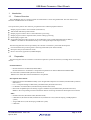
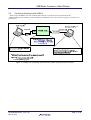
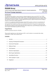
The USB-BASIC-F/W comes with a sample vendor class driver and application. USB Bulk and Interrupt data
transfers can be executed without modification to the firmware.
For RX62N RSK, USB PORT0 can be used as the USB peripheral port and USB PORT1 can be used as the USB
host port. Thus, this firmware enables the user to confirm operations of both USB-BASIC-F/W and RX62N RSK
without modification.
Fig.2.1 USB-BASIC-F/W USB Data Transfer Image
PIPE configurations are provided below. Note: transfer data is dummy data (00, 01, 02…).
Table2.1 PIPE Configurations
PIPE No.
Transfer Type
Max. Packet Size
PIPE0
Control
64 bytes
PIEP1
Bulk IN
64 bytes
PIPE2
Bulk OUT
64 bytes
PIPE6
Interrupt OUT
64 bytes
PIPE7
Interrupt IN
64 bytes
R01AN0495EJ0100 Rev.1.00
Apr 15, 2011
Page 3 of 32
USB Basic Firmware <Short Sheet>
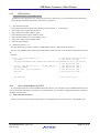
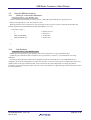
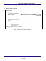
2.1.2
(1)
Setup
Hardware
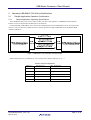
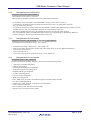
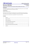
The connection topology for each device is described below.
Please refer to the corresponding instruction manual concerning RX62N RSK setup, emulator use, etc.
Emulator host PC
Use as USB
peripheral port
Use as USB
host port
USB
PORT0
User cable
RX62N RSK
USB
PORT1
Emulator cable
Emulator
RX62N USB Basic Firmware
(Use for USB peripheral and USB
host functions)
OS:Windows 2000,Windows XP
Integrated development environment:
High-performance Embedded Workshop (HEW)
C/C++ Compiler Package for RX Family
Figure 2.2 Device Connection Topology
(2)
Software
Source codes forUSB-BASIC-F/W can be compiled, linked and decoded in HEW4. To start up HEW4, double click
on the HEW workspace file (FW.hws) provided.
For RX62N RSK, upload the USB-BASIC-F/W sample program and execute according to the following steps.
1) Execute the HEW workspace file [Fw.hws] provided withUSB-BASIC-F/W.
2) Select the project and the build configuration, and then execute the build.
Select the project and build configuration as follows:
Project selection
NONS version: set NonOS_StdFw as active project
uITRON version: set Itron_StdFw as active project
Build configuration selection
Select one of the following. Only the selected source files will be compiled.
PORT0_P: use USB_PORT0 for peripheral functions
PORT1_H: use USB_PORT1 for host functions
PORT0_P_PORT1_H: use USB_PORT0 for peripheral functions and USB_PORT1 for host functions
R01AN0495EJ0100 Rev.1.00
Apr 15, 2011
Page 4 of 32
USB Basic Firmware <Short Sheet>
Build configuration can be customized.
When NonOS_StdFw is
selected as the active project
Only the specified source files will be compiled.
Figure.ure.2.5 Project Selection Examples (using HEW)
3)
4)
5)
6)
Select [Debug Æ Connect].
You will be prompted to select the emulator mode; select the mode according to the emulator you are using.
Download the program by selecting: [Debug Æ Download Æ All Download Modules].
Execute the program by selecting: [Debug Æ Execute after reset].
R01AN0495EJ0100 Rev.1.00
Apr 15, 2011
Page 5 of 32
USB Basic Firmware <Short Sheet>
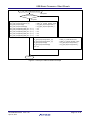
2.1.3
(1)
Sample Application Operation Image
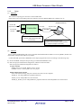
When running the sample application on one RX62N RSK device
USB-BASIC-F/W operations can be confirmed by selecting PORT0_P_PORT1_H in the build configuration in the
HEW environment, as shown in the connection image below. The USB bus analyzer can be used to monitor the
transmission contents of the USB data transfer.
Figure .2.2.Using one RX62N RSK Device
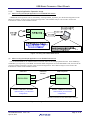
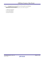
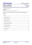
(2)
When running the sample application on two RX62N RSK devices
Use one RX62N RSK for the USB host functions and the other for the USB peripheral functions. Select PORT0_P
and PORT1_H, respectively, in the HEW environment build configuration for each USB-BASIC-F/W, and execute the
program. Confirm operations as shown in the connection image below. The USB bus analyzer can be used as the
transmission contents of the USB data transfer.
USB Host
USB Peripheral
USB data
transfer
USB
PORT0
USB
PORT0
USB
PORT1
USB
PORT1
RX62N RSK
RX62N RSK
RX62N USB Basic Firmware
RX62N USB Basic Firmware
(Select PORT1_H for the build
configuration)
Select PORT0_P for the build
configuration)
*Emulator connection has been abbreviated in this figure.
Figure .2.3 Using two RX62N RSK Devices
R01AN0495EJ0100 Rev.1.00
Apr 15, 2011
Page 6 of 32
USB Basic Firmware <Short Sheet>
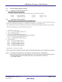
2.2
Confirming Operations with USBCV
When using USB-BASIC-F/W with USB peripheral functions, operations can be confirmed with the
“USBCommandVerifier (USBCV) without modifying USB-BASIC-F/W. The connection topology for each device is
shown below.
Figure .2.4 Example of Confirming Operations with USBCV (USB peripheral functions)
R01AN0495EJ0100 Rev.1.00
Apr 15, 2011
Page 7 of 32
USB Basic Firmware <Short Sheet>
3.
Customized USB-BASIC-F/W Operations
USB-BASIC-F/W can operate as a USB driver to match the user system by modifying the scheduler macro
(“r_usbc_cItron.h” / “r_usbc_cMacSystemcall.h”), user defined information (“r_usbc_cDefUsr.h”/ “r_usb_cDefUsr.h”),
and nonOS settings (“r_usbc_cKernelId.h” / “main.c” / “r_usb_PSMPL_apl.c” / “r_usb2_HSMPL_apl.c”), and adding
the nonOS HDCD/PDCD to the MainLoop function.
For more details, refer to the RX62N Group USB Basic Firmware Instruction Manual.
3.1
User Definitions
To use a customized USB-BASIC-F/W, each user definition must be modified to match the user system.
USB-BASIC-F/W is set to default values and must be modified by the user as necessary. For more details, refer to the
Chapter 5 (User Definitions) in the RX62N Group USB Basic Firmware Instruction Manual.
3.1.1
H/W Function Selection/Project Selection
The USB-BASIC-F/W sample program comprises the following two HEW projects. Select the appropriate project as
needed.
NonOS_StdFw: nonOS version
Itron_StdFw: uITRON version
You can also customize the build configuration to fit your user system by selecting one of the following:
PORT0_P: use USB_PORT0 for peripheral functions
PORT1_H: use USB_PORT1 for host functions
PORT0_P_PORT1_H: use USB_PORT0 for peripheral functions and USB_PORT1 for host functions
The selected source files will be compiled.
Build configuration.can be customized.
When NonOS_StdFw is
selected as the active project
Only the specified files will be compiled.
Figure .3.5 Figure 3.5 Project Selection Example (using HEW)
R01AN0495EJ0100 Rev.1.00
Apr 15, 2011
Page 8 of 32
USB Basic Firmware <Short Sheet>
3.1.2
Changed items for RX62N CPU
Changed file name:[main.c] [RX62NRSK.c]
The changed items for CPU are as follows.
These should be changed as needed to match the system under development.
⎯ Initialization of the control MCU, interrupt handlers, interrupt control, DTC control, etc.
⎯ Adjustments to the duration of the specified wait time functions (usbc_cpu_DelayXms () function,
usbc_cpu_Delay1us() function)
⎯ For the non-OS firmware, settings of functions that disable or enable USB-related interrupts in order to use the
scheduler function (usb_cstd_IntDisable() function, usb_cstd_IntEnable() function)
The interrupt disable function (usb_cstd_IntDisable() function) and interrupt enable function
(usb_cstd_IntEnable() function) disable and enable, respectively, USB interrupts on the RX62N. Make any
necessary changes to the settings to match the MCU being used.
3.1.3
Changed items for H/W setting
Changed file name:[usb_cstd_Pinconfig() is included in r_usb_cSignal.c]
The changed items for Hardware setting are as follows.
⎯
⎯
⎯
⎯
⎯
3.1.4
External bus operating voltage (set by r_usbc_cDefUsr.h)
FIFO access endian specification (common with CPU endian mode: set by user-defined information)
Interrupt pin operation level
DTC pin operation level
Low-power sleep operation specification (set by r_usbc_cDefUsr.h)
Changed items for user system
Changed file name: [r_usbc_cDefUsr.h]
The items listed below should be changed to match the system under development.
⎯
⎯
⎯
⎯
⎯
⎯
⎯
⎯
⎯
⎯
⎯
⎯
⎯
⎯
Operating environment designation
USB port specification
Create Systemcall designation (uITRON)
Target device/target system designation
Installed USB-IP type designation
Transfer speed designation
CPU byte endian designation
Width of bus designation
PID = NAK setting at transfer end enable designation (peripheral function mode)
Low Power Mode designation
Software retry count at pipe no-response (host function mode)
Control read data buffer size
Device address initial value (host function mode)
Hub down port count (host function mode)
R01AN0495EJ0100 Rev.1.00
Apr 15, 2011
Page 9 of 32
USB Basic Firmware <Short Sheet>
3.1.5
Changed items for user definition (H/W operation specification)
Changed file name: [r_usb_cDefUsr.h]
These should be changed as needed to match the system under development.
⎯
⎯
⎯
⎯
USB function designation
Clock mode designation
Sleep mode designation
H/W adress designation
R01AN0495EJ0100 Rev.1.00
Apr 15, 2011
Page 10 of 32
USB Basic Firmware <Short Sheet>
3.2
Use as USB peripheral function
3.2.1
Setting of Vendor ID/ Product ID
Changed file name:[ r_usbc_cDefUsr.h]
It is necessary to change Vendor ID/ Product ID that uses the system under development.
#define
#define
3.2.2
USB_VENDORID
USB_PRODUCTID
0x1234u
0x5678u
/* Vendor ID */
/* Product ID * /
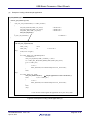
Descriptor Table Generation
Changed file name:[ r_usb_PSMPL_data.c] [ r_usb_PSMPL_apl.c]
In order for USB-BASIC-F/Wto operate in peripheral function mode, it is necessary to create a descriptor table that
matches the system under development. (A sample table is included in r_usb_PSMPL_data.c.)
In the sample table the portions changed by the program are indicated by the designation USBC_SOFT_CHANGE.
The descriptor definitions comprise the following four types.
1)
Standard Device Descriptor
uint8_t usb_gpstd_SmplDeviceDescriptor[]
2) Device Qualifier Descriptor
uint8_t usb_gpstd_SmplQualifierDescriptor[]
3) Configuration/Other_Speed_Configuration(*)/Interface/Endpoint
uint8_t usb_gpstd_SmplConfigurationH_1[](*)
uint8_t usb_gpstd_SmplConfigurationF_1[]
4) String Descriptor
uint8_t usb_gpstd_StringDescriptor1[]
uint8_t usb_gpstd_StringDescriptor2[]
uint8_t usb_gpstd_StringDescriptor3[]
uint8_t usb_gpstd_StringDescriptor4[]
uint8_t usb_gpstd_StringDescriptor5[]
*This setting is not used by the RX62N.
PDCD must generate Configuration/Other_Speed_ConfigurationDescriptor when a USB reset is detected.
Notes: 1. For details of each descriptor, see chapter 9 of the USB revision 2.0 specification.
2. When making changes to descriptor definitions, it is also necessary to make changes to the pipe
information table to match the endpoint descriptors. (A sample table is included in
r_usb_PSMPL_data.c.)
R01AN0495EJ0100 Rev.1.00
Apr 15, 2011
Page 11 of 32
USB Basic Firmware <Short Sheet>
R_usb_pstd_SmplDescriptorChange
Full-speed
Hi-speed connection
Hi-speed
usb_gpstd_SmplConfigurationH_1[1]
= USBC_DT_CONFIGURATION;
usb_gpstd_SmplConfigurationF_1[1]
= USBC_DT_OTHER_SPEED_CONF;
usb_gpstd_SmplConPtr[0]
= usb_gpstd_SmplConfigurationH_1;
usb_gpstd_SmplConPtrOther[0]
= usb_gpstd_SmplConfigurationF_1;
usb_gpstd_SmplEpTbl1[(USB_EPL * 0) + 3]
= 512;
usb_gpstd_SmplEpTbl1[(USB_EPL * 1) + 3]
= 512;
usb_gpstd_SmplEpTbl1[(USB_EPL * 2) + 3]
= 512;
usb_gpstd_SmplEpTbl1[(USB_EPL * 3) + 3]
= 512;
usb_gpstd_SmplEpTbl1[(USB_EPL * 4) + 3]
= 512;
usb_gpstd_SmplConfigurationF_1[1]
= USBC_DT_CONFIGURATION;
usb_gpstd_SmplConfigurationH_1[1]
= USBC_DT_OTHER_SPEED_CONF;
usb_gpstd_SmplConPtr[0]
= usb_gpstd_SmplConfigurationF_1;
usb_gpstd_SmplConPtrOther[0]
= usb_gpstd_SmplConfigurationH_1;
Mxps = 64;
return
Figure 3.1 Descriptor Table Generation Example
R01AN0495EJ0100 Rev.1.00
Apr 15, 2011
Page 12 of 32
USB Basic Firmware <Short Sheet>
3.2.3
PIPE Definition
Changed file name:[ r_usb_PSMPL_data.c]
PDCD must store appropriate pipe settings for the relevant class driver as a pipe information table. PDCD must
register the pipe information table at the time of driver registration.
1)
Pipe Information Table
A pipe information table comprises the following six items (uint16_t × 6: [RX-62N]).
1.
2.
3.
4.
5.
6.
2)
Pipe window select register (address 0x64)
Pipe configuration register (address 0x68)
Pipe buffer designation register (address 0x6A)
Pipe maximum packet size register (address 0x6C)
Pipe period control register (address 0x6E)
FIFO port usage method
Definition of Pipes 1 to 9
The pipe definitions provided as a sample in USB-BASIC-F/W are configured as shown below.
The file r_usb_PSMPL_data.c contains macro definitions for the items that can be included in the information table
are.
Example:
uint16_t usb_gpstd_SmplEpTbl1 [] = {
← Registered information table
USB_PIPE1,
← Pipe definition item 1
USB_BULK|USB_BFREOFF|USB_DBLBOFF|USB_CNTMDOFF|USB_SHTNAKON|USB_DIR_P_OUT|USB_EP1,
← Pipe definition item
(uint16_t)USB_BUF_SIZE(512u) | USB_BUF_NUMB(8u), ← Pipe definition item 3
USB_SOFT_CHANGE,
← Pipe definition item 4
USB_IFISOFF | USB_IITV_TIME(0u),
← Pipe definition item 5
USB_CUSE,
← Pipe definition item 6
:
:
USB_PDTBLEND
← End of Pipe table
};
3.2.4
How to Start/Register the PDCD
To run peripheral functions with the USB-BASIC-F/W firmware, you will need to create a PDCD based on the user
system, and register that PDCD in the PCD. For nonOS firmware, you will need to configure the PDCD to enable the
scheduler control function.
(1)
PCD Task Start Sequence
The start sequence of the PCD task is shown below. The sample application is described in r_usb_PSMPL_apl.c.
R01AN0495EJ0100 Rev.1.00
Apr 15, 2011
Page 13 of 32
USB Basic Firmware <Short Sheet>
: Processing only nonOS
usbc_cstd_Main
Task
MainInit
MainInit()
Initialize
hardware
Start Idle task
Wait for
hardware ready
hardware
usb_cstd_TargetInit()
usb_cstd_WaitUsbip()
usb_cstd_AsspConfig()
Pin control 1
MainLoop
usb_cstd_SwReset()
Software reset
usb_cstd_InitialClock()
Idle task
Start oscillator
usb_cstd_Pinconfig()
Pin control 2
R_usb_pstd_PcdOpen()
Start PCD tak
PCD task
R_usb_pstd_SmplRegistration()
Register drivers
Set PERI
function
usb_cstd_SetHwFunction(USBC_PERI)
Return
MainLoop
Task processing
flag set?
PCD task
PDCD task
No
USBC_TRCV_MSG
Scheduler
Command processing
Return
Figure 3.2 PCD Start Sequence
R01AN0495EJ0100 Rev.1.00
Apr 15, 2011
Page 14 of 32
USB Basic Firmware <Short Sheet>
(2)
Register the PDCD
The structure used to register information in PDCD is described below. The call-back function is executed when the
device state changes, etc.
The sample application is described in the R_usb_pstd_SmplRegistration function in r_usb_PSMPL_apl.c.
typedef struct {
uint16_t
**pipetbl;
/* Pipe Define Table address */
uint8_t
*devicetbl;
/* Device descriptor address */
uint8_t
*qualitbl;
/* Qualifier descriptor address */
uint8_t
**configtbl;
/* Configuration descriptor address */
uint8_t
**othertbl;
/* Other speed descriptor address */
uint8_t
**stringtbl;
/* String descriptor address */
USBC_CB_INFO_t
classinit;
/* Driver init */
USBC_CB_INFO_t
devdefault;
/* Device default */
USBC_CB_INFO_t
devconfig;
/* Device configuered */
USBC_CB_INFO_t
devdetach;
/* Device detach */
USBC_CB_INFO_t
devsuspend;
/* Device suspend */
USBC_CB_INFO_t
devresume;
/* Device resume */
USBC_CB_INFO_t
interface ;
/* Interface changed */
USBC_CB_TRN_t
ctrltrans;
/* Control Transfer */
}USBC_PCDREG_t;
R01AN0495EJ0100 Rev.1.00
Apr 15, 2011
Page 15 of 32
USB Basic Firmware <Short Sheet>
Table 3.1 Members of USB_PCDREG_t Structure
Variable Name
**pipetbl
*devicet
*qualitbl
**configtbl
**othertbl
**stringtbl
classinit
devdefault
devconfig
devdetach
devsuspend
devresume
interface
ctrltrans
Description
Register the address of the pipe information table.
Register the device descriptor address.
Register the device qualifier descriptor address.
Register the address of the configuration descriptor address table.
Register the address of the other speed descriptor address table.
Register the address of the string descriptor address table.
Register the function to be started when initializing PDCD.
It is called at registration.
Register the function to be started when transitioning to the default state.
It is called when a USB reset is detected.
Register the function to be started when transitioning to the configured state.
It is called in the SET_CONFIGURATION request status stage.
Register the function to be started when transitioning to the detach state.
It is called when a detached condition is detected.
Register the function to be started when transitioning to the suspend state.
It is called when a suspend condition is detected.
Register the function to be started when transitioning to the resume state.
It is called when a resume condition is detected.
Register the function to be started when an interface change occurs.
It is called in the SET_INTERFACE request status stage.
Register the function to be started when a user-initiated control transfer occurs.
R01AN0495EJ0100 Rev.1.00
Apr 15, 2011
Page 16 of 32
USB Basic Firmware <Short Sheet>
3.2.5
Example of Creating a Peripheral Application
The following is an example of embedding a USB-BASIC-F/W data transfer sample application. For more details, refer to
r_usb_PSMPL_apl.c.
(1)
Example of creating a main task
“r_usb_PSMPL_apl.c”
void usbc_cstd_MainTask(USBC_VP_INT stacd)
{
/* Sample application initial process */
usb_pstd_MainInit();
Å USB function Initialization(Start the PCD, Register the PDCD)
Refer to 3.2.5(2)
/* Idle Task Start process */
usbc_cstd_IdleTaskStart();
/* Sample application main loop process */
while( 1 )
{
usb_pstd_MainLoop();
Å Mainloop (Applicaton)
/* Condition compilation by the difference of the operating system */
#if USBC_FW_PP == USBC_FW_NONOS_PP
/* Idle Task (sleep sample) */
usbc_cstd_IdleTask(0);
#endif /* USBC_FW_PP == USBC_FW_NONOS_PP */
}
}
Refer to 3.2.5(3)
Figure.3.3 Example of coding a Peripheral Application (1)
R01AN0495EJ0100 Rev.1.00
Apr 15, 2011
Page 17 of 32
USB Basic Firmware <Short Sheet>
Example of creating register the PCDC
(2)
“r_usb_PSMPL_apl.c”
void usb_pstd_MainInit(void)
{
usb_cstd_TargetInit();
usb_pstd_PrAplTitle();
/* Wait USB-H/W access enable */
usb_cstd_WaitUsbip();
/* Set ASSP pin_config */
usb_cstd_AsspConfig();
usb_cstd_SwReset();
/* Start clock */
usb_cstd_InitialClock();
/* Set pin_config */
usb_cstd_Pinconfig();
R_usb_pstd_PcdOpen();
R_usb_pstd_SmplRegistration();
Å Register the sample PDCD driver(*)
/* Condition compilation by the difference of the operating system */
#if USBC_FW_PP == USBC_FW_NONOS_PP
/* Scheduler init */
usbc_cstd_ScheInit();
usb_pstd_SetTaskPri();
#endif /* USBC_FW_PP == USBC_FW_NONOS_PP */
usb_cstd_SetHwFunction(USBC_PERI);
USBC_DLY_TSK(500);
}
*:You can also create/register thePDCD to fit your user system.
Figure.3.4 Example of coding a Peripheral Application (2)
R01AN0495EJ0100 Rev.1.00
Apr 15, 2011
Page 18 of 32
USB Basic Firmware <Short Sheet>
(3)
Example of coding a Peripheral sample application
“r_usb_PSMPL_apl.c”
void usb_pstd_MainLoop(void)
{
if( R_usbc_cstd_CheckSchedule() == USBC_FLGSET )
{
/* PCD Task */
usb_pstd_PcdTask((USBC_VP_INT)0);
/* Main Task */
usb_pstd_MainTask((USBC_VP_INT)0);
}
/* Scheduler */
R_usbc_cstd_Scheduler();
}
“r_usb_PSMPL_apl.c”
void usb_pstd_MainTask(USBC_VP_INT stacd)
Å Sample application for Data transmission (*)
{
USBC_ER_t
USBC_UTR_t
uint16_t pipe;
uint8_t
err;
*mess;
*bufp;
/* Condition compilation by the difference of the operating system */
#if USBC_FW_PP == USBC_FW_OS_PP
/* User Data Initialize */
usb_ptsd_UsrDataInit();
/* User Data Transfer Start */
usb_pstd_UsrDataTranStart();
#endif /* USBC_FW_PP == USBC_FW_OS_PP */
(skip)
*:You can also create/register the application to fit your user system.
Figure.3.5 Example of coding a Peripheral Application (3)
R01AN0495EJ0100 Rev.1.00
Apr 15, 2011
Page 19 of 32
USB Basic Firmware <Short Sheet>
3.3
Use as USB host function
3.3.1
Setting of a connected USB device
Changed file name:[ r_usb2_HSMPL_apl.c]
A TPL is generated for each device class. In project, vendor IDs and product IDs are registered as sets.
Register all supported sets in the relevant device class.
When all products in the relevant device class are supported, do not specify specific vendor IDs and product IDs.
Instead, register USB_NOVENDOR and USB_NOPURODUCT as a set.
const uint16_t tpl[] = {
1,
0,
USB_NOVENDOR,
USB_NOPRODUCT,
};
/* Number of list */
/* Reserved */
/* Vendor ID */
/* Product ID */
};
3.3.2
Pipe Definition
Changed file name:[ r_usb2_HSMPL_data.c]
HDCD must store appropriate pipe settings for the relevant class driver as a pipe information table.
Update the pipe information table to match the user system. Refer to section 3.2.3 for information concerning
definitions.
Note that the pipe information table must be updated to match the connected device. The USB-BASIC-F/W is
equipped with usb_hstd_ChkPipeInfo() to analyze the descriptor it receives from the device (Endpoint Descriptor) and
update the data in the pipe information table. It also comes with usb_hstd_SetPipeInfo() for setting the updated
information in the pipe information table. The user can use these functions to update the pipe information table to match
the connected device.
R01AN0495EJ0100 Rev.1.00
Apr 15, 2011
Page 20 of 32
USB Basic Firmware <Short Sheet>
3.3.3
How to Start/Register the HDCD
To execute host functions with the USB-BASIC-F/W firmware, you will need to create an HDCD based on the user
system, and register that HDCD in the HCD/MGR. For nonOS firmware, you will need to configure the HDCD to
enable the scheduler control function.
(1)
HCD Task Start Sequence
The start sequence of the HCD/MGR task is shown below.
The sample is described in r_usb2_HSMPL_apl.c.
R01AN0495EJ0100 Rev.1.00
Apr 15, 2011
Page 21 of 32
USB Basic Firmware <Short Sheet>
Figure 3.6 HCD/MGR Start Sequence
R01AN0495EJ0100 Rev.1.00
Apr 15, 2011
Page 22 of 32
USB Basic Firmware <Short Sheet>
(2)
Register the HDCD
The structure used to register information in PDCD is described below. The sample application is described in the
R_usb_hstd_SmplRegistration function inusb2_HSMPL_apl.c.
typedef struct {
uint16_t
rootport;
/* root port */
uint16_t
devaddr;
/* Device address */
uint16_t
devstate;
/* Device satate */
uint16_t
ifclass;
/* Interface Class */
uint16_t
*tpl;
/* Target Peripheral List */
uint16_t
*pipetbl ;
/* Pipe Define Table address */
USBC_CB_INFO_t
classinit;
/* Driver init */
USBC_CB_CHECK_t
classcheck;
/* Driver check */
USBC_CB_INFO_t
devconfig;
/* Device configuered */
USBC_CB_INFO_t
devdetach;
/* Device detach */
USBC_CB_INFO_t
devsuspend;
/* Device suspend */
USBC_CB_INFO_t
devresume;
/* Device resume */
USBC_CB_INFO_t
overcurrent;
/* Device over current */
}USBC_HCDREG_t;
Table.3.2 Members of USBC_HCDREG_t Structure
Variable Name
rootport
devaddr
devstate
ifclass
*tpl
*pipetbl
classinit
classcheck
devconfig
devdetach
devsuspend
devresume
overcurrent
Description
Used by HCD. The connected port number is registered.
Used by HCD. The device address is registered.
Used by HCD. The device connection state is registered.
Register the interface class code for HDCD operation.
Register the target peripheral list for HDCD operation.
Register the address of the pipe information table.
Register the function started at driver registration.
Register the function started at HDCD checking operation.
It is called when a TPL match occurs.
Register the function to be started when transitioning to the configured state.
It is called in the SET_CONFIGURATION request status stage.
Register the function to be started when transitioning to the detach state.
Register the function to be started when transitioning to the suspend state.
Register the function to be started when transitioning to the resume state.
Register the function started when overcurrent detection occurs.
R01AN0495EJ0100 Rev.1.00
Apr 15, 2011
Page 23 of 32
USB Basic Firmware <Short Sheet>
3.3.4
Example of Creating a Host Application
The following is an example of embedding a USB-BASIC-F/W data transfer sample application. . For more details, refer to
r_usb2_HSMPL_apl.c.
(1)
Example of creating a main task
“r_usb2_HSMPL_apl.c”
void usbc_cstd_MainTask(USBC_VP_INT stacd)
{
/* Sample application initial process */
usb2_hstd_MainInit();
Å USB function Initialization(Start the HCD, Register the HDCD)
Refer to 3.3.4(2)
/* Idle Task Start process */
usbc_cstd_IdleTaskStart();
/* Sample application main loop process */
while( 1 )
{
usb2_hstd_MainLoop();
Å Mainloop(Application)
/* Condition compilation by the difference of the operating system */
#if USBC_FW_PP == USBC_FW_NONOS_PP
/* Idle Task (sleep sample) */
usbc_cstd_IdleTask(0);
#endif /* USBC_FW_PP == USBC_FW_NONOS_PP */
}
}
Refert to 3.3.4(3)
Figure.3.7 Example of coding a Host Application(1)
R01AN0495EJ0100 Rev.1.00
Apr 15, 2011
Page 24 of 32
USB Basic Firmware <Short Sheet>
Register the HDCD
(2)
“r_usb2_HSMPL_apl.c”
void usb2_hstd_MainInit(void)
{
usb2_cstd_TargetInit();
usb2_hstd_PrAplTitle();
/* Target initialize */
/* Print title */
usb2_cstd_WaitUsbip();
usb2_cstd_AsspConfig();
usb2_cstd_SwReset();
usb2_cstd_InitialClock();
usb2_cstd_Pinconfig();
/* Wait USB-H/W access enable */
/* Set ASSP pin_config */
/* Start clock */
/* Set pin_config */
R_usb2_hstd_MgrOpen();
R_usb2_hstd_HcdOpen();
R_usb2_hstd_SmplRegistration();
usb2_hstd_HubRegistAll();
/* Manager open */
/* Hcd open */
/* Registration */
Å Register the sample HDCD driver (*)
/* Hub registration */
/* Condition compilation by the difference of the operating system */
#if USBC_FW_PP == USBC_FW_NONOS_PP
usbc_cstd_ScheInit();
/* Host scheduler init */
usb2_hstd_SetTaskPri();
#endif /* USBC_FW_PP == USBC_FW_NONOS_PP */
usb2_cstd_SetHwFunction(USBC_HOST);
}
*:You can also create/register the HDCD to fit your user system.
Figure..3.8 Example of coding a Host Application (2)
R01AN0495EJ0100 Rev.1.00
Apr 15, 2011
Page 25 of 32
USB Basic Firmware <Short Sheet>
(3)
Example of coding a Host sample application
“r_usb2_HSMPL_apl.c”
void usb_pstd_MainLoop(void)
{
if( R_usbc_cstd_CheckSchedule() == USBC_FLGSET )
{
usb2_hstd_HcdTask((USBC_VP_INT)0);
usb2_hstd_MgrTask((USBC_VP_INT)0);
usb2_hhub_Task((USBC_VP_INT)0);
usb2_hcls_SmplTask();
}
R_usbc_cstd_Scheduler();
}
/* HCD Task */
/* MGR Task */
/* HUB Task */
/* Scheduler */
“r_usb2_HSMPL_apl.c”
void usb2_hcls_SmplTask(void)
{
USBC_UTR_t
*mess;
USBC_ER_t
err;
/* Error code */
(skip)
switch( mess->msginfo )
{
case USBC_MSG_CLS_CHECKREQUEST:
/* Enumeration */
usb2_hcls_SmplEnue((USBC_CLSINFO_t *) mess);
err = USBC_REL_BLK(USB2_HSMP_MBX,(USBC_MH_t)mess);
if( err != USBC_OK )
{
/* error */
USBC_PRINTF0("### USB HostSampleClass rel_blk error¥n");
}
break;
(skip)
case USBC_MSG_CLS_TASK:
usb2_hstd_MainTask(mess);
Å Sample application for Data transmission (*)
break;
if( err != USBC_OK )
{
/* error */
USBC_PRINTF0("### USB HostSampleClass rel_blk error¥n");
}
break;
(skip)
*:You can also create/register the application to fit your user system.
Figure.3.9 Example of coding a Host Application (3)
R01AN0495EJ0100 Rev.1.00
Apr 15, 2011
Page 26 of 32
USB Basic Firmware <Short Sheet>
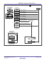
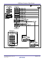
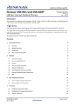
4.
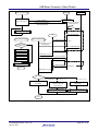
Software Configuration
USB-BASIC-F/W comprises the peripheral driver, which implements the peripheral function mode, the Host driver,
which implements the host function mode, the Host manager, which manages device states, the HUB class driver,
which controls devices connected to the down ports of the USB hub, and the main task, which operates as the
application.
The peripheral driver and the Host driver initiate hardware control according to messages from the various tasks.
They also notify the appropriate task when hardware control ends, of processing results, and of hardware requests.
USB-BASIC-F/W is equipped with the following for hardware control requests: PCD API (for PDCD layer to use);
MGR API, HCD API, and HUBAPI (for HDCD layer to use). Each API functions are contained in the following files.
For details on these API functions, refer to the Renesas RX62N Group USB Basic Firmware Instruction Manual.
• The PCD API functions are contained in the file “r_usb_pDriverAPI”.
• The HCD and MGR API functions are contained in the file “r_usb_hDriverAPI”.
• The HUB API functions are contained in the file “r_usb_hHubsys.c (NONS version) ” or
” r_usb_hHubsys_uitron.c(uITRON version)”
Figure 4.1 Software Configuration of USB-BASIC-F/W
R01AN0495EJ0100 Rev.1.00
Apr 15, 2011
Page 27 of 32
USB Basic Firmware <Short Sheet>
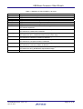
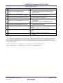
Table 4.1 Task Functions
No
1
Module Name
USB interrupt handler
void usb_cstd_UsbHandler(void)
2
Peripheral driver(PCD)
void usb_pstd_PcdTask(USBC_VP_INT_t)
Host driver (HCD)
void usb2_hstd_HcdTask(USBC_VP_INT_t)
Host manager (MGR)
void usb2_hstd_MgrTask(USBC_VP_INT_t)
3
4
5
6
Hub class driver (HUBCD)
void usb2_hhub_Task(USBC_VP_INT_t)
USB Peripheral Device class driver(PDCD)
7
USB Host Device class driver (HDCD)
8
Application (APL)
Function
• USB interrupt handler
(USB packet transmit/receive end and special
signal detection)
• Hardware control in peripheral function mode
• Peripheral transaction management
• Hardware control in host function mode
• Host transaction management
• Device state management
• Enumeration
• HCD/HUBCD control message determination
• HUB down port device state management
• HUB down port enumeration
Provided by the customer as appropriate for the
system.
Refer to Chapter.3.2 to how to provide.
Provided by the customer as appropriate for the
system.
Refer to Chapter.3.3 to how to provide.
Provided by the customer as appropriate for the
system.
In the same manner USB-BASIC-F/W comprises tasks that implement control functions for USB data transmit and
receive operations, USB-BASIC-F/W comprises tasks that implement control functions for USB data transmit and
receive operations. When an interrupt occurs, the selected function mode is checked and notification is sent by means of
a message to PCD/HCD.
Refer to the sample file ‘r_usb_PSMPL_apl.c’ and Figure.4.2 for USB peripheral function.
Refer to the sample file ‘r_usb_HSMPL_apl.c’ and Fig.4.3 for USB Host function.
R01AN0495EJ0100 Rev.1.00
Apr 15, 2011
Page 28 of 32
USB Basic Firmware <Short Sheet>
usbc_cstd_MainTask()
PCD
Driver registration
(Requisite PDCD registration)
usb_pstd_MainInit
HOST
PCD Start
USB Host
connection
(VBUS detection)
CallbackRegistration()
D+ Pull-up
usb_pstd_MainLoop()
Enumeration
SET_CONFIGURATION
PDCD
usb_pstd_MainLoop()
Callback devconfig
R_usb_pstd_SmplOpen()
No
Flag set
usb_ptsd_UsrDataInit()
Initialize a Data area
Yes
usb_pstd_PcdTask
usb_pstd_MainTask
usb_pstd_UsrDataTranStart()
Start the data transfer
R_usbc_cstd_Scheduler()
usb_pstd_UserDataTrans()
return
R_usb_pstd_TransferStart()
Data transfer
usb_pstd_MainTask()
Callback Complete
usb_pstd_SmplTransResult()
rcv_msg?
N
Y
usb_pstd_UsrDataTran()
Data transfer
Return
Figure.4.2 Sequence Outline for Periferal Sample application
R01AN0495EJ0100 Rev.1.00
Apr 15, 2011
Page 29 of 32
USB Basic Firmware <Short Sheet>
usb2_hstd_MainTask()
MGR/HCD
MGR/HCD Start
Driver registration
(Requisite HDCD registration)
usb2_hstd_MainInit
USB device
USB device connection
(Attach detection)
CallbackRegistration()
Reset
usb2_hstd_MainLoop()
Enumeration
GET_DESCRIPTOR
HDCD
usb2_hstd_MainLoop()
Task processing
flag set?
usb2_hcls_SmpTask()
Callback Classcheck
R_usb2_hstd_SmplClassCheck
USBC_MSG_CLS_CHC
EKREQUEST
No
SET_CONFIGURATION
Yes
usb2_hstd_HcdTask
Callback devconfig
R_usb2_hstd_SmplOpen()
usb2_hstd_MgrTask
USBC_MSG_CLS_INIT
usb2_hhub_Task
R_usb2_hstd_TransferStart()
usb2_hcls_SmplTask
Data transfer
R_usbc_cstd_Scheduler()
Callback Complete
usb2_hstd_SmplPipeTransferResult
Return
USBC_MSG_CLS_TASK
rcv_msg?
USBC_MSG_CLS_CHCEKREQUEST
usb2_hcls_SmplEnue()
Enumeration
USBC_MSG_CLS_INIT
usb2_hcls_SmplInit()
Initialize a Data area
Data transfer
usb_hstd_SmplPipeTransfer()
USBC_MSG_CLS_TASK
Usb2_hstd_MainTask()
Data transfer
usb_hstd_SmplPipeTransfer()
Return
Fig.4.3 Sequence Outline for Host Sample application
R01AN0495EJ0100 Rev.1.00
Apr 15, 2011
Page 30 of 32
USB Basic Firmware <Short Sheet>
4.1
List of Files
4.1.1
Folder Structure
The folder structure in which the files are provided in USB-BASIC-F/W is shown below.
RX62N is equipped with two independent USB ports: USBSTDFW for PORT0 and USB2STDFW for PORT1.
The user’s operating environment and USB functions are readily supported in the HEW environment, making it easy
for the user to select only the target source files. This allows unnecessary source files (source codes) to be separated for
the compile, eliminating the extra burden on ROM/RAM capacity.
<USB-BASIC-F/W Folder
Fw.hws
HEW Workspace File
<WorkSpace>
+⎯⎯⎯ USBSTDFW :For PORT0
|
+⎯⎯⎯ class
|
|
+⎯⎯⎯ hubd Sample hub driver
|
|
+⎯⎯⎯ smpl USB standard request sample
⎯⎯⎯
|
+
include
Common header file
|
+⎯⎯⎯ USB20
|
+⎯⎯⎯ HCD Host control driver
|
+⎯⎯⎯ PCD Peripheral control driver
|
+⎯⎯⎯ LIB
Common library
+⎯⎯⎯ USB2STDFW :For PORT1
|
+⎯⎯⎯ class
|
|
+⎯⎯⎯ hubd
Sample hub driver
⎯⎯⎯
|
|
+
smpl
USB standard request sample
|
+⎯⎯⎯ include
Common header file
|
+⎯⎯⎯ USB20
|
+⎯⎯⎯ HCD Host control driver
|
+⎯⎯⎯ PCD Peripheral control driver
|
+⎯⎯⎯ LIB
Common library
+⎯⎯⎯ USBCSTDFW
|
+⎯⎯⎯ include
Common library
⎯⎯⎯
+
SmplMain
|
+⎯⎯⎯ APL
Sample application
|
+⎯⎯⎯ Project
Project
R01AN0495EJ0100 Rev.1.00
Apr 15, 2011
Page 31 of 32
USB Basic Firmware <Short Sheet>
Website and Support
Renesas Electronics Website
http://www.renesas.com/
Inquiries
http://www.renesas.com/inquiry
All trademarks and registered trademarks are the property of their respective owners.
R01AN0495EJ0100 Rev.1.00
Apr 15, 2011
Page 32 of 32
Revision Record
Rev.
1.00
Date
Apr.15.11
Description
Summary
Page
—
First edition issued
A-1
General Precautions in the Handling of MPU/MCU Products
The following usage notes are applicable to all MPU/MCU products from Renesas. For detailed usage notes on the
products covered by this manual, refer to the relevant sections of the manual. If the descriptions under General
Precautions in the Handling of MPU/MCU Products and in the body of the manual differ from each other, the
description in the body of the manual takes precedence.
1. Handling of Unused Pins
Handle unused pins in accord with the directions given under Handling of Unused Pins in the manual.
⎯ The input pins of CMOS products are generally in the high-impedance state. In operation with an unused
pin in the open-circuit state, extra electromagnetic noise is induced in the vicinity of LSI, an associated
shoot-through current flows internally, and malfunctions occur due to the false recognition of the pin state as
an input signal become possible. Unused pins should be handled as described under Handling of Unused Pins
in the manual.
2. Processing at Power-on
The state of the product is undefined at the moment when power is supplied.
⎯ The states of internal circuits in the LSI are indeterminate and the states of register settings and pins are
undefined at the moment when power is supplied.
In a finished product where the reset signal is applied to the external reset pin, the states of pins
are not guaranteed from the moment when power is supplied until the reset process is completed.
In a similar way, the states of pins in a product that is reset by an on-chip power-on reset function
are not guaranteed from the moment when power is supplied until the power reaches the level at
which resetting has been specified.
3. Prohibition of Access to Reserved Addresses
Access to reserved addresses is prohibited.
⎯ The reserved addresses are provided for the possible future expansion of functions. Do not access these
addresses; the correct operation of LSI is not guaranteed if they are accessed.
4. Clock Signals
After applying a reset, only release the reset line after the operating clock signal has become stable.
When switching the clock signal during program execution, wait until the target clock signal has
stabilized.
⎯ When the clock signal is generated with an external resonator (or from an external oscillator) during a reset,
ensure that the reset line is only released after full stabilization of the clock signal. Moreover, when
switching to a clock signal produced with an external resonator (or by an external oscillator) while program
execution is in progress, wait until the target clock signal is stable.
5. Differences between Products
Before changing from one product to another, i.e. to one with a different type number, confirm that the
change will not lead to problems.
⎯ The characteristics of MPU/MCU in the same group but having different type numbers may differ because
of the differences in internal memory capacity and layout pattern. When changing to products of different
type numbers, implement a system-evaluation test for each of the products.
Notice
1.
All information included in this document is current as of the date this document is issued. Such information, however, is subject to change without any prior notice. Before purchasing or using any Renesas
Electronics products listed herein, please confirm the latest product information with a Renesas Electronics sales office. Also, please pay regular and careful attention to additional and different information to
be disclosed by Renesas Electronics such as that disclosed through our website.
2.
Renesas Electronics does not assume any liability for infringement of patents, copyrights, or other intellectual property rights of third parties by or arising from the use of Renesas Electronics products or
technical information described in this document. No license, express, implied or otherwise, is granted hereby under any patents, copyrights or other intellectual property rights of Renesas Electronics or
others.
3.
You should not alter, modify, copy, or otherwise misappropriate any Renesas Electronics product, whether in whole or in part.
4.
Descriptions of circuits, software and other related information in this document are provided only to illustrate the operation of semiconductor products and application examples. You are fully responsible for
the incorporation of these circuits, software, and information in the design of your equipment. Renesas Electronics assumes no responsibility for any losses incurred by you or third parties arising from the
use of these circuits, software, or information.
5.
When exporting the products or technology described in this document, you should comply with the applicable export control laws and regulations and follow the procedures required by such laws and
regulations. You should not use Renesas Electronics products or the technology described in this document for any purpose relating to military applications or use by the military, including but not limited to
the development of weapons of mass destruction. Renesas Electronics products and technology may not be used for or incorporated into any products or systems whose manufacture, use, or sale is
prohibited under any applicable domestic or foreign laws or regulations.
6.
Renesas Electronics has used reasonable care in preparing the information included in this document, but Renesas Electronics does not warrant that such information is error free. Renesas Electronics
7.
Renesas Electronics products are classified according to the following three quality grades: "Standard", "High Quality", and "Specific". The recommended applications for each Renesas Electronics product
assumes no liability whatsoever for any damages incurred by you resulting from errors in or omissions from the information included herein.
depends on the product's quality grade, as indicated below. You must check the quality grade of each Renesas Electronics product before using it in a particular application. You may not use any Renesas
Electronics product for any application categorized as "Specific" without the prior written consent of Renesas Electronics. Further, you may not use any Renesas Electronics product for any application for
which it is not intended without the prior written consent of Renesas Electronics. Renesas Electronics shall not be in any way liable for any damages or losses incurred by you or third parties arising from the
use of any Renesas Electronics product for an application categorized as "Specific" or for which the product is not intended where you have failed to obtain the prior written consent of Renesas Electronics.
The quality grade of each Renesas Electronics product is "Standard" unless otherwise expressly specified in a Renesas Electronics data sheets or data books, etc.
"Standard":
Computers; office equipment; communications equipment; test and measurement equipment; audio and visual equipment; home electronic appliances; machine tools;
personal electronic equipment; and industrial robots.
"High Quality": Transportation equipment (automobiles, trains, ships, etc.); traffic control systems; anti-disaster systems; anti-crime systems; safety equipment; and medical equipment not specifically
designed for life support.
"Specific":
Aircraft; aerospace equipment; submersible repeaters; nuclear reactor control systems; medical equipment or systems for life support (e.g. artificial life support devices or systems), surgical
implantations, or healthcare intervention (e.g. excision, etc.), and any other applications or purposes that pose a direct threat to human life.
8.
You should use the Renesas Electronics products described in this document within the range specified by Renesas Electronics, especially with respect to the maximum rating, operating supply voltage
range, movement power voltage range, heat radiation characteristics, installation and other product characteristics. Renesas Electronics shall have no liability for malfunctions or damages arising out of the
use of Renesas Electronics products beyond such specified ranges.
9.
Although Renesas Electronics endeavors to improve the quality and reliability of its products, semiconductor products have specific characteristics such as the occurrence of failure at a certain rate and
malfunctions under certain use conditions. Further, Renesas Electronics products are not subject to radiation resistance design. Please be sure to implement safety measures to guard them against the
possibility of physical injury, and injury or damage caused by fire in the event of the failure of a Renesas Electronics product, such as safety design for hardware and software including but not limited to
redundancy, fire control and malfunction prevention, appropriate treatment for aging degradation or any other appropriate measures. Because the evaluation of microcomputer software alone is very difficult,
please evaluate the safety of the final products or system manufactured by you.
10. Please contact a Renesas Electronics sales office for details as to environmental matters such as the environmental compatibility of each Renesas Electronics product. Please use Renesas Electronics
products in compliance with all applicable laws and regulations that regulate the inclusion or use of controlled substances, including without limitation, the EU RoHS Directive. Renesas Electronics assumes
no liability for damages or losses occurring as a result of your noncompliance with applicable laws and regulations.
11. This document may not be reproduced or duplicated, in any form, in whole or in part, without prior written consent of Renesas Electronics.
12. Please contact a Renesas Electronics sales office if you have any questions regarding the information contained in this document or Renesas Electronics products, or if you have any other inquiries.
(Note 1)
"Renesas Electronics" as used in this document means Renesas Electronics Corporation and also includes its majority-owned subsidiaries.
(Note 2)
"Renesas Electronics product(s)" means any product developed or manufactured by or for Renesas Electronics.
http://www.renesas.com
SALES OFFICES
Refer to "http://www.renesas.com/" for the latest and detailed information.
Renesas Electronics America Inc.
2880 Scott Boulevard Santa Clara, CA 95050-2554, U.S.A.
Tel: +1-408-588-6000, Fax: +1-408-588-6130
Renesas Electronics Canada Limited
1101 Nicholson Road, Newmarket, Ontario L3Y 9C3, Canada
Tel: +1-905-898-5441, Fax: +1-905-898-3220
Renesas Electronics Europe Limited
Dukes Meadow, Millboard Road, Bourne End, Buckinghamshire, SL8 5FH, U.K
Tel: +44-1628-585-100, Fax: +44-1628-585-900
Renesas Electronics Europe GmbH
Arcadiastrasse 10, 40472 Düsseldorf, Germany
Tel: +49-211-65030, Fax: +49-211-6503-1327
Renesas Electronics (China) Co., Ltd.
7th Floor, Quantum Plaza, No.27 ZhiChunLu Haidian District, Beijing 100083, P.R.China
Tel: +86-10-8235-1155, Fax: +86-10-8235-7679
Renesas Electronics (Shanghai) Co., Ltd.
Unit 204, 205, AZIA Center, No.1233 Lujiazui Ring Rd., Pudong District, Shanghai 200120, China
Tel: +86-21-5877-1818, Fax: +86-21-6887-7858 / -7898
Renesas Electronics Hong Kong Limited
Unit 1601-1613, 16/F., Tower 2, Grand Century Place, 193 Prince Edward Road West, Mongkok, Kowloon, Hong Kong
Tel: +852-2886-9318, Fax: +852 2886-9022/9044
Renesas Electronics Taiwan Co., Ltd.
13F, No. 363, Fu Shing North Road, Taipei, Taiwan
Tel: +886-2-8175-9600, Fax: +886 2-8175-9670
Renesas Electronics Singapore Pte. Ltd.
1 harbourFront Avenue, #06-10, keppel Bay Tower, Singapore 098632
Tel: +65-6213-0200, Fax: +65-6278-8001
Renesas Electronics Malaysia Sdn.Bhd.
Unit 906, Block B, Menara Amcorp, Amcorp Trade Centre, No. 18, Jln Persiaran Barat, 46050 Petaling Jaya, Selangor Darul Ehsan, Malaysia
Tel: +60-3-7955-9390, Fax: +60-3-7955-9510
Renesas Electronics Korea Co., Ltd.
11F., Samik Lavied' or Bldg., 720-2 Yeoksam-Dong, Kangnam-Ku, Seoul 135-080, Korea
Tel: +82-2-558-3737, Fax: +82-2-558-5141
© 2011 Renesas Electronics Corporation. All rights reserved.
Colophon 1.1