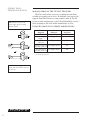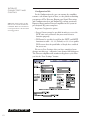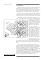
1
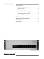
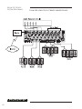
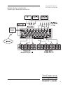
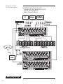
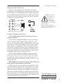
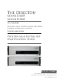
The Director ® Model D4400 Model D3400 16 Channel High Efficiency • Digital Signal Processor • Ethernet Interface & Control Power Amplifier Professional Installer’s Gratification Guide ® Making Good Sound Great 22410 70th Avenue West • Seattle, WA 98043 USA 425-775-8461 • Fax 425-778-3166 • www.audiocontrol.com ©2013. All rights reserved. Important Information Dealer Name______________________________________ Date Installed___________________________________ Serial Number____________________________________ Ethernet MAC Address__________________________ IP Address Dynamic / Static____________________ ® Table of Contents Table of Contents The Director Model D3400 • Model D4400 Cool and Different Features . . . . . . . . . . . . . . . . . . . . . . . . . . 2 A Guided Tour Front Panel . . . . . . . . . . . . . . . . . . . . . . . . . . . . . . . . . . . . . 5 Rear Connections . . . . . . . . . . . . . . . . . . . . . . . . . . . . . . . . 6 Making sense of the trigger ins and outs . . . . . . . . . . . . . . 8 Internet Connectivity and Control Control using a browser . . . . . . . . . . . . . . . . . . . . . . . . . . . 9 Control and Queries via Telnet . . . . . . . . . . . . . . . . . . . . 14 Operation without an Ethernet connection . . . . . . . . . . 17 Hook-up Guide with System Diagrams . . . . . . . . . . . . . . . 18 An Introduction to Acoustics and Equalizers Room Acoustics . . . . . . . . . . . . . . . . . . . . . . . . . . . . . . . . . 22 Benefits of Equalization . . . . . . . . . . . . . . . . . . . . . . . . . . 23 Adjusting the Signal Processing Equalizing the System . . . . . . . . . . . . . . . . . . . . . . . . . . . . . . . 24 Parametric and Graphic Equalization . . . . . . . . . . . . . . . 25 Subsonic and Tweeter Protection Filters . . . . . . . . . . . . . 26 Memories . . . . . . . . . . . . . . . . . . . . . . . . . . . . . . . . . . . . . . 26 A Brazen Plug . . . . . . . . . . . . . . . . . . . . . . . . . . . . . . . . . . . . . 27 more TheDirector® Model D3400 • Model D4400 Installer’s Guide Table of Contents Advanced Topics Speaker and wiring impedance . . . . . . . . . . . . . . . . . . . . 28 Amplifier bridging . . . . . . . . . . . . . . . . . . . . . . . . . . . . . . . 29 In wall volume controls . . . . . . . . . . . . . . . . . . . . . . . . . . . 29 Installation of multiple units of The Director . . . . . . . . 30 Level matching and gain controls . . . . . . . . . . . . . . . . . . 31 Sound level (SPL) in large areas and unique rooms . . . 31 Troubleshooting . . . . . . . . . . . . . . . . . . . . . . . . . . . . . . . . . . . 33 Warranty and Service Information . . . . . . . . . . . . . . . . . . . 35 Block Diagram . . . . . . . . . . . . . . . . . . . . . . . . . . . . . . . . . . . . 37 Specifications . . . . . . . . . . . . . . . . . . . . . . . . . . . . . . . . . . . . . 38 The Director Model D3400 ® Introduction Introduction To label The Director® Models D4400 and D3400 just multi-zone amplifiers is like calling a Ferrari just a car. There is so much more to both products in terms of performance and capability. Ethernet control, unparalleled energy efficiency, rack saving compact design, superb sound quality and bulletproof reliability are just a few key features of The Director. More features are discussed in the next section so please read on. Since we build The Director Models in the AudioControl factories in the Northwest Rainforest outside of Seattle, USA, we can continually improve it and our other products. Similarly, the AudioControl web site is regularly updated. We encourage you to check our web site, www.audiocontrol.com, if something is not answered in this manual. Of course, you can always chat with us on the phone during normal business hours. Lastly, this is a professional installer’s manual. We assume you are experienced with multi-channel amplifiers and the Ethernet. The product setup, adjustment and operation require network access. The Director is a registered trademark. TheDirector® Model D3400 • Model D4400 Installer’s Guide 1 Cool & Different Features Cool and Different Features Volume Control The primary focus of our latest firmware is volume control via browser or Telnet commands. You can now control volume in any zone! Control via the browser will allow you to control volume in any zone along with EQ and source selection. With the updated Telnet control, you have the means to control the Maximum On volume so that when you turn the unit on volume is set to a predefined value. This is for those nights you were rocking out with the volume turned up to eleven - the next morning you won’t blast your ears out. Also with Telnet control, you can control volume of groups by the volume set commands. Another benefit of the software update is speed - faster communication for better integration into control systems! Unlike Other Amplifiers Here is a list and description of features that are part of The Director series from AudioControl. Most are rare or nonexistent in other companies’ amplifiers. • DHCP: An IP address for The Director Model D3400 and D4400 is obtained via DHCP by default. If a DHCP server is not found on the network, The Director Model D3400 and The Director Model D4400 will default to 192.168.0.249. • UPnP: Device discovery is enabled on The Director Models D3400 and D4400 for ease of connectivity from a PC. • Numbering: In the device discovery /UPnP window, if you are using multiple Director amplifiers, you will find that each Director is numbered in the sequence they were added onto the network. • Groups: Grouping has been enabled for quick control of zones through Telnet commands. Up to 4 groups can be defined for control over Standby and Source Selection. • Import/Export: Exporting and Importing of the amplifier’s settings – including EQ settings – has been enabled. Now you can configure your EQ settings as a template and apply these to each Director amplifier in your system.A little refining of those settings for each amp and you will be in and out in no time. ® 2 • Ethernet Control: Via a browser or Telnet commands you can control and query almost all the functions of The Director. You can mute zones, change source inputs, adjust equalization, recall memories, check line voltage, display protection logs and get an email if something goes wrong. And this is only a partial list! • Signal Processing: You have at your command graphic equalization, parametric equalization, tweeter protection filters and low frequency cutoff filters. In addition, you can set up two zones with a two way crossover. The equalizer settings are ganged left and right channels together or your can separate. Plus, there are three memories to save and recall settings. • Unparalleled energy efficiency: Whether from the point of view of saving electricity or from the viewpoint of less heat in the rack, The Director has no equal. It is VERY energy efficient during operation and equally impressive with its efficiency during standby. • Save rack spaces: With 16 channels in only three rack spaces, you save one or even two spaces over other amplifiers. • Lightdrive Anti-clipping: With durability in mind, Lightdrive anti-clipping protection defends the system against clipping, distortion, damage and even teenage parties. • Self resetting Protection Features: Protection features in The Director are extensive and include thermal, short circuit, clipping, ultrasonic and DC offset among others. If the fault is removed, the amplifier resets. Plus, The Director can send you an email if something happens. • Superior Sound Quality: Pristine sonics happens first in all AudioControl designs and is not compromised by any other feature. You get the feeling that sound quality is an after thought with products from other companies. • Reliable and Rugged: From the beefy rack mounts to the brawny transformer mounting, The Director continues with AudioControl’s legacy of building bulletproof product. • Pacific Northwest Heritage: Hard to believe, but we make this product in the USA. We are very proud of that fact. What is more important to you is the care we craft in at every step and the extensive knowledge we have in all aspects of the product. Plus, we back this up with a five year warranty. Cool & Different Features TheDirector® Model D3400 • Model D4400 Installer’s Guide 3 Really Cool Stuff in The Director As great as these features on the previous page are, here is a list of some of the new and unique parts of The Director; • Output Present LED: Ever wonder if there really was a signal on the speaker outputs of an amp? No wondering with The Director because there is an LED flickering with the signal level right next to each speaker connector. • Very Low Standby Current: When The Director is in Standby, ready to turn on via a trigger, it draws less than 5 watts. Compare that to a typical amplifier. • Name the Zone: Use the browser to type in any name on the zone. Also give The Director amplifier a specific name so that you can easily identify it when there is more than one in the system. • Digital Signal Sense: Signal sense is digital, accurate and reliable. Rejoice. • Ground Lift Switch: Here is a legal and safe way to combat 60 cycle hum. If the flip of this switch solves the problem, maybe you can get home earlier tonight. • 12 Volt Trigger Outs: Every multi-zone amp has trigger ins. The Director has regular trigger ins, plus triggering via the Ethernet, and it has mini-jack 12 volt trigger outs for turning on another component or two. • Front Level Display: We think the front panel level display is way cool, pretty, and useful. However, if you want to turn it off, we have provided a switch to do so. • Times Square Light Show: Look at the rear of The Director and we forgive you if you think of Times Square in New York City. There are indicator LEDs aplenty. Not only for the speaker outputs but also for signal sense, mono switching, local input active, and ethernet bypass. On the rear panel there are 30 indicator LEDs in total (that is not a typo). Counting the front panel indicator LEDs, the total is 66! If we can make your system setup faster, we want to. ® 4 A Guided Tour Of The Director Model D3400 / D4400 1 2 3 4 5 Front Panel 1 Power LED - Starting with the easy one... 4 Zone Status LEDs - At the bottom of the columns are the channel status LEDs which are dual color and serve two purposes. First, they illuminate Blue when the corresponding two channels are active and operating properly. The second function of the status LED is to turn Red if something has caused that zone to go into protection. when you have the AC Power switch on the back panel turned on and The Director is plugged into an active AC outlet, this little Blue light will beam forth. 2 Protection LED - There are two states to this LED. In normal operation it glows Blue when the unit is on and in standby or operating. If this LED is Red, then one of the internal protection circuits is activated. 3 Network LEDs - You have seen this type of LED a million times on computer network cards. One shows an active connection while the other LED flickers with the passage of data. There is a duplicate set on the rear panel. 5 Level Activity LEDs - These three LEDs dance with the music. They tell you that signal is passing in each zone and at what level. It is an attractive and useful light show, but if you really want, you can turn this off with a switch on the rear panel. TheDirector® Model D3400 • Model D4400 Installer’s Guide 5 A Guided Tour Of The Director Model D3400 / d4400 1 2 5 3 6 7 4 Rear Panel 1 2 Ethernet LAN Connection - Plug The Director into a 10BaseT network here. The internal web server allows remote control of all channels, signal processing and source selection. See the section on Internet Connectivity and Control for detailed information. Ethernet Triggered LED - When this LED is on, the unit is being “triggered” via the Ethernet and the 12 volt mini jacks are active and powered for turning on some components. 3 Bypass Switch and LED - For diagnostics only. This button disables all the Ethernet control and forces all channels on. If there is a problem with the home automation system and you really need music, this is quite useful. 4 Ground Lift Switch - Be safe, use this switch instead of a “cheater” plug. The switch selects the isolation between the audio ground and the AC earth ground. In normal operation, the switch should be in the Ground position. If there is AC hum, try the other two settings. For safety, the chassis is always connected to earth ground regardless of the switch setting. 5 Bus Inputs 1 and 2 - These inputs provide two distribution busses for sending a common signal to multiple zones. The bus input switch ® 6 8 on each amplifier zone, or the ethernet control, selects which input is playing in that specific zone. For Bus 1, the second pair of jacks can be used to daisy chain to another multi-zone amplifier. 6 Local Inputs - Any standard line level audio signal may be connected to these inputs. As the name implies, this source will be available only in a particular zone and only if switched to local via the ethernet control or the zone switch. 7 Input Gain Control - Use a screwdriver to adjust this level control for the input sensitivity of the zone. In general, you want the gains turned down, counterclockwise, and the pre-amp level running stronger for best signal to noise. 8 Source Select Switches - The “Bus 1/Net” setting allows the source to be selected via ethernet commands and the browser interface or come from “Bus 1” in the absence of a ethernet connection. If the switch is in “Bus 2” or “Local”, the audio signal will come from that source and can not be changed by ethernet commands. more rear panel features on the next page A Guided Tour Of The Director Model D3400/ D4400 19 10 9 10 11 11 12 13 14 15 16 Master Power Switch - This switch controls the main AC power. Since The Director draws only a few watts during standby, the only time you need to turn the master power off is if the system is going to be shut down for an extended time. 9 17 18 LED) of only this zone. To bridge two channels, this button must be in. 14 Remote Power Control - If you are not using 15 the ethernet control, you can remotely turn The Director on with this connector. Use a contact closure between +12 VDC and Trigger In or an external 12 volt trigger between Trigger in and Ground or use the mini jacks as inputs. The +12 VDC Out is not designed to power other equipment. 16 Remote Power Control Mini (1/8”) Jacks These are mono 1/8” jacks wired in parallel to each other and work in conjunction with the 3 pin remote power connector. Either 1/8” input 17 may receive a 12 VDC trigger that will turn on the amplifier. The unused jack can then be used to turn on a second amplifier. If you use the 3 pin connector to trigger the amplifier -18 or use the ethernet control-- both of the mini jacks are powered with 12 VDC. 12 Signal Sense Defeat - Signal presence on The 19 Director is digitally sensed by the DSP, very accurate, and a great power saver. Push this button in to defeat Signal Sense and have all amp channels on at all times. When defeated the LED will glow a fetching red. 13 Mono - Pressing in this button sums the left and right signals (and lights the indicator Speaker Outputs - Cool terminal blocks which are designed to make an installer smile. They make it very simple to pre-wire a system and easy to trouble-shoot wiring and speakers. Yes they will take big wire. Output Present LED - Even cooler than the speaker blocks is this LED which flickers with the level of the music. Ever wonder if there was really signal coming out of the amp when the speakers are at the other end of the house? Now you know. Local Trigger Active LED - If there is no source plugged into the local jacks and this LED is glowing, there will be the sounds of silence. Another LED to speed up troubleshooting. Front Level Display - If you don’t want the dancing lights on the front panel, then push this in. On the other hand, those lights are very useful to know what is going on. Power Cord - A standard IEC cord goes here. Since The Director at full power draws 1300 watts, this should be a 16 Ga. cord or better. Fuse - The Director has several layers of internal - and self resetting - protection circuitry. This fuse is just in case something really awful goes wrong. Rejoice, there are no internal fuses in this amplifier. TheDirector® Model D3400 • Model D4400 Installer’s Guide 7 Guided Tour Trigger Ins & Outs Making Sense of the 12 Volt Triggers The Director has five ways you can bring the unit from standby to on and ready to serve. In addition, you can use the triggers from The Director to turn on more units of The Director or other components as well. All this flexibility can be a little daunting so the table below should make it clear. Note: Do not use any 12 volt power trigger if you are using ethernet control. Using Bus Inputs to Create Larger Zones How Triggered Ethernet 12 volt mini plug input* Jumped Phoenix connector Contact closure on Phoenix connector 12 volt input on Phoenix connector LED Indicator Ethernet Triggered 12 v Trigger Active Mini Jacks Powered* Yes Yes, unused jack 12 v Trigger Active Yes 12 v Trigger Active Yes 12 v Trigger Active Yes * +12 volts on tip, mono jack Note: The 12 volt trigger outs are not for and cannot power a device, just turn on. ® 8 Internet Connectivity and Control Setting up The Director Model D3400 or D4400 is a breeze. Just plug it into an existing network and let the DHCP server assign The Director amplifier an IP address. The Director amplifier will then show up in your network device list, if “network discovery” has been enabled in your Windows computer. Double click the icon for the amp and your browser should open to The Director’s Operations page. Alternative methods of connecting are described below. Other than connecting to the browser for initial set up, configuration and EQ settings, you will be able to control the amplifier via Telnet (pages 14-16). This is done through the telnet port 23. Internet Connectivity and Control Important Note: If you are connecting multiple units on a network, The Directors will number themselves for immediate identification as they are powered up with a network connection .They should be viewable from the Discovered Devices list in your Windows computer. Later on, you can rename them. Control Using a Browser General For Microsoft operating systems: There are multiple ways to connect to The Director amplifier. The simplest way is to connect The Director, via the Ethernet port, to a network with a DHCP server. The Director will obtain a local address from the DHCP server. The Director amplifier should appear in the list of network resources. If it does not appear within a minute or so, double check and make sure that you have enabled network discovery or UPnP devices to be shown. If no DHCP server has been enabled in your network, or you would like to directly connect to The Director amplifier, use an Ethernet cable and connect the two devices together. The default IP address of The Director amplifier is 192.168.0.249 when a DHCP server is unavailable, so in order to connect to The Director, you will need to give your computer a static IP address. Important Note: DCHP is default for The Director and UPnP/device discovery is enbled. However, if a DCHP server is not found, the Director’s default IP address is 192.168.0.249. If you aren’t using DCHP and plan to assign static addresses, individually set the IP address by connecting directly to The Director amplifier with a computer first. Never allow two devices with the same IP address on the network. In your Windows based computer, change your computer’s IP address to a static address of 192.168.0.x – where x is a value between 1 through 248 or 250 through 254. If you don’t know where to start to find out how to give your computer a static IP address, please consult the Interwebs. Be sure not to use a static IP address for your computer that is in use by another device – an IP address should be unique across the local network – if it is not you’re going to have a bad time. TheDirector® Model D3400 • Model D4400 Installer’s Guide 9 Internet Connectivity and Control For Apple/Mac Desktops and Laptops: Apple does not support UPnP device discovery. Your easiest method for connecting with a Mac is to directly connect to The Director amplifier. The default IP address of The Director amplifier is 192.168.0.249 so in order to connect to The Director, you will need to give your computer a static IP address. Change your Mac’s IP address to a static address of 192.168.0.x – where x is a value between 1 through 248 or 250 through 254. If you don’t know where to start to find out how to give your computer a static IP address, please consult the Interwebs. Be sure not to use a static IP address for your computer that is in use by another device – an IP address should be unique across the local network – if it is not you’re going to have a bad time. ® 10 Operation Tab The first page you see when connecting to The Director the first time via a web browser will be the Operations page. The functionality and controls on this page are described below: Groups: Grouping allows for channels to be grouped for control via telnet for simple efficient operations. The telnet commands are listed on page 15. Grouping allows for quick control over the on/off and signal source states of each group. Internet Connectivity and Control Note: The rear panel switch for a zone must be in “Bus 1/Net” position for Ethernet switching of sources. Standby: The standby on/off buttons control the state of each individual channel – whether the channel is on or not. Signal Source: Specifies where each channel pair is getting it’s input source. Trim:Trim the levels of the input – in addition to the physical gain adjustments on the back of the amplifier. Temperature: Provides status of channel temperature Protection: Shows channel protection status At the top of the page, you can check the line voltage, the global on/off state of the unit (good place to check if you aren’t getting audio), whether signal sense is engaged, and note the number of logs. The log count is also a link to a pop up page which will describe the most recent events. If you are not able to control signal sense or turn The Director on or off, check the rear of the unit to see if one of the switches there is over-riding these controls or if the Ethernet control is bypassed. TheDirector® Model D3400 • Model D4400 Installer’s Guide 11 Internet Connectivity and Control Configuration Tab In the Configuration tab, you can rename the amplifier, rename each channel pair or Zone, set the global networking parameters of The Director, Export your Signal Processing and Configuration data and Import EQ settings previously Exported from another Director amplifier in the system or pre-designed EQ curve templates. Note: Rear Panel switches on The Director can override the Ethernet commands. Make sure the Ethernet is not bypassed nor is the unit hardwired triggered on. Important Configuration options: • Server Gateway must be specified in order to access the SNTP time server, likewise for your email alerts to function properly. • DNS must be specified as well for the SNTP and SMTP functions to work – 8.8.8.8 (Default) or 8.8.4.4 are public DNS servers that the good folks at Google have enabled for you to use Be sure to Save Settings after you have completed your changes on this page – otherwise your changes will disappear. The Director amplifier will automatically power cycle when you hit the “Save Settings” button. ® 12 Signal Processing Tab Graphic equalization is by individual zone and with both channels within that zone paired by default. You can “unlock” the zone/channel pair by clicking the “Unlock” checkbox for each respective band. You also have the option of setting the EQ curve globally for The Director by enabling the “All Zones” checkbox. Setting the EQ is done by dragging the EQ slider to the desired position, by clicking where you want the position/ value to be or by clicking the +/- buttons. Please see a later section for a discussion of the methods and benefits of equalization. The two bands of parametric equalization are by zone with both channels locked at all times. Parametric equalization can be very powerful however it takes some work to adjust properly, can easily be done wrong, and is much easier to use if you have some instrumentation/audio analysis gear. See the later section for more discussion on EQ. Saving EQ memories and Import/Export: It is important to save your Signal Processing to a memory. If you do not need to have multiple EQ memories for recall, it is still necessary for the Signal Processing to be saved should the power go out. When saving your Signal Processing, the Save function saves all 8 zones of Signal Processing. Once these are saved, you can export these settings from the configuration page for back up purposes or for making a template that can be repeatedly used. To prevent overstress of speakers by sending frequencies lower than they are physically able to handle, use the subsonic filter. For most inwall speakers, we recommend a setting of 40 Hz or higher. Contrary to popular thought, higher often sounds better for this low frequency filter. Similarly, to save the tweeters, be conservative with the setting of the tweeter protection filter. It could save you a service call. Internet Connectivity and Control TheDirector® Model D3400 • Model D4400 Installer’s Guide 13 Internet Connectivity and Control Being that you can pull a large amount of power – up to 100 watts! – from each and every channel from The Director Model D4400 (65 watts with The Director Model D3400), you just might want to use a sub in one of the bigger rooms No problem at all – enable the crossover function and bridge the output from Zone 1 for your sub and use Zone 2 for you highs. Feed your input into channel pairs 1-2. In this configuration, any input on Zone 2 or channel pair 3-4 will be ignored. Only these two Zones may be used with the crossover function. See System Diagrams for pictorial of this. You may save all of the information on this page by selecting “Save Current Memory”. All the graphic and parametric equalizer settings as well as any crossover setting will be retained in that number memory. The information saved in the memory is the information on this Signal Processing web page since the information on the other pages is saved separately. Control Via Telnet Commands To control The Director Model D3400 or D4400 in an automation network, you will need a controller that can send and receive telnet commands and responses. The command and response structures of the controls provided via telnet are in simple human – ASCII - language. Power on is simply “power 1” with a carriage return (<cr>, /r or 0x0D) to end the command string. Feedback from The Director is not automatic though the command received by The Director is echoed back to the controller. To verify that the command changed The Director to the desired state, you can send a Query. The Director will respond to the query as per the table defined on page 16. Notes on control commands: • For a global state change such as power, the basic structure is: the command, space, then the parameter followed by a carriage return. Example to turn on the power of the unit and check to see if power is on: ® 14 Command: Query: Response: power 1<cr> power?<cr> power 1 • For controlling zones, the structure is: the command, space then the zone number or numbers also separated by a space and a carriage return. Example to turn zones 3, 5 and 6 off from an all channels on state: Command: Query: Response: Internet Connectivity and Control mute 3 5 6 <cr> mute? <cr> 0,0,1,0,1,1,0,0 Note: The query “mute?” yields a description of the mute/ off state across all channel pairs/zones; 1 equals positive (that the channel pair/zone is off) and 0 (zero) is negative (that the channel pair/zone is not off), relative to the actual query and channel pair/zone. Control Commands power 0 Main Power Off (zero not ‘O’) power 1 Main Power On volume_inc [1-8] Increases zone [1-8] volume in 1 dB increments volume_dec [1-8] Decreases zone [1-8] volume in 1 dB increments volume_set [1-8] [1-100] Sets volume to specific value volume_set_group [1-4] [1-100] Sets volume of group to specific value volume_max_on_set [1-100] Sets maximum turn-on volume mute_group [1-4] Turns groups 1 through 4 off unmute_group [1-4] Turns groups 1 through 4 on mute [1-8] Mute Zone(s) unmute [1-8] Unmute Zone(s) bus1_group [1-4] Changes source to bus1 for groups [1-4] bus2_group [1-4] Changes source to bus2 for groups [1-4] local_group [1-4] Changes source to local for groups [1-4] bus1 [1-8] Switch Zone(s) to Bus #1 bus2 [1-8] Switch Zone(s) to Bus #2 local [1-8] Switch Zone(s) to Local input signalsense 0 Signal sense off (zero) signalsense 1 Signal sense on clearlog Clears log memory [x] Switch to memory 1, 2, or 3 timeout [x] Number of seconds before session timeout TheDirector® Model D3400 • Model D4400 Installer’s Guide 15 Internet Connectivity and Control Inquiry Commands volume_set? Returns volume level for zones 1-8 Example: Returns 11 11 13 57 47 65 49 51 Zone 5 then is set to 47 mute? Returns which zones are muted unmute? Returns which zones are unmuted bus1? Returns which zones are switched to bus#1 bus2? Returns which zones are switched to bus #2 local? Returns which zones are switched to local input signalsource? Returns a list showing the source for each zone Example: 1,3,2,3,3,1,1,2 where 1 is Bus #1 and 3 is Local ® 16 temp? Returns a value for each zone where cool is 1, warm is 2 and hot is 3 power? On is 1 and off is 0 (zero) acvoltage? Responses are; 1 is low, 2 is normal and 3 is high protection? For each zone, the responses are: 1 is normal, 2 is muted, 3 is protect and 4 is short circuit signalsense? On is 1 and off is 0 (zero) timeout? Number of seconds before inactive session terminated bypass? Physical bypass switch engaged is 1, 0 is not engaged log? Protection data log - see below Memory? Responds with 0, 1, 2, 3 where 0 is the current configuration, not a saved memory Logging Format In response to a logging inquiry (log?), The Director will respond with the most recent fifty events. The format of the logged response is: Internet Connectivity and Control EECCYYYYMMDDHHMMSS where E= event code, C=zone, Y= year, M= month, D= day, H= hour, M= minute and S=second. Event code include: 01= DC offset/global protection 02= short circuit 03= over temperate 04= Line voltage high 05= Line voltage low For the zone code: 00 channel pair 1-2 01 channel pair 3-4 02 channel pair 5-6 03 channel pair 7-8 04 channel pair 9-10 05 channel pair 11-12 06 channel pair 13-14 07 channel pair 15-16 99 all zones, i.e. global protection Operation Without An Ethernet Connection To operate The Director without an Ethernet connection, in an emergency, or while troubleshooting, press in the “Ethernet Bypass” button on the rear of the unit. The indicator LED will glow red. Now you can trigger the unit on and off via the 12 volt trigger in a conventional fashion. The slide switches at the top for each zone will select Bus 1, Bus 2, or the local input. Unfortunately, you will have no control over the signal processing, however this will let you get music from the system in an emergency. TheDirector® Model D3400 • Model D4400 Installer’s Guide 17 Hook Up Guide System Diagrams Using Bus Inputs to Create Larger Zones ® 18 Whole House System with Tuner Only Background Music Hook Up Guide System Diagrams TheDirector® Model D3400 • Model D4400 Installer’s Guide 19 Hook Up Guide System Diagrams Multiple Unit System with • Tuner Only Background Music • Tuner Triggered on • Daisy Chained Bus 1 ® 20 Using the Crossover Option Hook Up Guide System Diagrams TheDirector® Model D3400 • Model D4400 Installer’s Guide 21 Room Acoustics Acoustics Magazine reviewers and audio system owners spend much time critically appraising speakers and other audio components. Unfortunately, a phenomenon that has a very large effect upon sound is not easily judged or changed. That effect is the ACOUSTICS of the environment in which you are listening. Room acoustics is a complicated subject about which entire textbooks have been written. We simply want you to be aware of a few basics that have a direct effect on real time audio analysis. As you probably learned in high school, sound travels in waves. In an audio system, these waves are created by the speakers. Like waves in a pond created by a splash, sound waves emanate from the transducers (speakers) and spread out into the room. If your room were infinitely big, that’s all there would be to it. But just as waves in a pond reach the bank and reflect back, sound waves bounce off walls, ceilings, and floors, reflecting, reinforcing and canceling each other as shown in the figure above. Since sound is energy, the way it reflects depends upon the angle of the surface, the type of material and the frequency Room interaction of the sound wave. Because your listening position is likely to be towards the back of the Free Field (waves shown in the diagram), you also get part of the reflected Reverberant Field as well. Now we add the next set of complications: Different frequencies of sound have different wave lengths (a function of frequency and the speed of sound). Each frequency’s wavelength contributes differently to the Free and Reverberant Fields because they are different sizes. For example, a 32 Hz bass note has a wavelength of 35 FEET, while a 16,000 Hz note has a wavelength just under a tenth of an inch. Tiny treble waves can be caught and neutralized by draperies, carpeting, upholstered furniture and gangs of indolent Persian cats…while gigantic bass waves simply slosh back and forth in the room. ® 22 Equalization Benefits Another set of variables is the shape and volume of your listening room. Large rooms require more bass energy to excite waves within them. Small rooms need less energy, but reflect it differently. And then there’s the fact that most rooms don’t have four walls anymore, but open into dining rooms, lofts, cathedral ceilings, etc. All of this means that predicting sound interaction patterns is very difficult due to the irregularities of the room shape. As you can see, room acoustics is an important but complicated subject. To learn more about room acoustics, get a copy of AudioControl’s Technical Paper 107, “Small Room Acoustics De-Mythologized”. You can download this paper from www.audiocontrol.com (search “De-mythologized”) or if you’re still into the printed page, call us and we’ll mail you a copy. The overall point that we’re trying to make is that the various rooms in a home function as gigantic mechanical equalizers, boosting or cutting certain frequencies depending on size, shape, volume, acoustic treatment and the position of the speakers. Benefits of Equalization Rarely is the room and room decor designed to get the most out of the audio system. In fact, almost always the opposite is the case where the speaker positions and sizes are dictated by some factors which are actually contrary to good sound. This real world situation is where equalization can provide great benefits. Speaker positions, furniture, and general room layouts may cause peaks in the frequency response. Fortunately these peaks can be tamed by judicious equalization. Also, it may be that the client has specific tastes, such as being the most interested in hearing voices such as ball game broadcasts, and you can tailor the sound to these tastes. Remember there are memories in The Director and you could use different settings via the memories for different sources. At all times, though, the laws of physics are hard to violate. Equalization can not make terrible acoustics sound terrific, only better. If the room has a tile floor and glass walls for example, the best case results will still be pretty bad by most measures. Further, while equalization can do wonders to help a less than perfect speaker, nothing will make a mediocre speaker sound fabulous. In other words, for best results, start with good speakers and reasonable room acoustics, if possible. TheDirector® Model D3400 • Model D4400 Installer’s Guide 23 Adjusting the Signal Processing Adjusting the Signal Processing Equalizing the System Before proceeding on equalizing the system, it is a good idea to make sure everything is connected and working properly. You know how to check connections and here are some reminders specific to The Director, as well as the steps to equalize. 1. Turn on the system. The Power light on the left front panel should be blue . 2. Connect to this specific unit of The Director over the network by entering its unique IP address into a browser (Firefox, Safari, Internet Explorer are preferred). 3. Make sure the unit is turned on and turn off signal sense in the Operation page on the browser. On the front panel all zone status lights should start red and then turn to blue. If any are not blue, check the Operation page to see if you need to unmute any zones. Note: For the absolutely best results, the equalizer controls on The Director D3400 should be adjusted with a real time analyzer such as the AudioControl Industrial SA-3052. Visit www. audiocontrolindustrial.com for more analysis products. 4. Play pink noise through the system into the zones you are going to adjust. If needed, there is a pink noise audio file at www.audiocontrol.com. Search for “pink noise”. The signal is playing through The Director when the LED’s level meter on front panel responds to the volume. 5. Assuming you have wireless network access, now grab your trusty real time analyzer (RTA) and go into the zone you wish to adjust. 6. Place the microphone in the middle of the area of listening at the height of the typical listeners head. 7. In general, use the equalizer controls to lower peaks in the frequency response first. Peaks obscure the surrounding sounds and lowering the peaks will unleash overshadowed sounds. There is more information in the next section on equalization and AudioControl has factory training, called Train in the Rain where we explore this subject in depth. SA-3052 Real Time Spectrum Analyzer 8. You can save different settings to different memories and see which one the clients like. Their taste may be different than yours. ® 24 Parametric and Graphic Equalization Adjusting the Signal Processing The graphic equalization controls in The Director are selected to correspond with the characteristics of wall and ceiling speakers and as such are very effective. Graphic controls are the easiest to tune and provide a “graphic” representation of what the adjustments are. Parametric equalization requires selecting the frequency, the bandwidth of the control, as well as the level of adjustment, not an easy task to get correct. In general, parametric equalization is valuable for very large areas of change or very narrow areas. Parametric equalization in The Director most likely is best used for taming very narrow peaks. Do not use for very narrow dips as these dips are likely caused by cancellations and will not respond to equalization boost. Here is an introduction to each of the graphic control frequencies and what their affect is on music. 45Hz — Low bass. This is about the lowest frequency which in-wall, extension and small bookshelf speakers can achieve. Boosting it too far might cause problems, even though The Director’s subsonic filter cuts frequencies below your adjustment point. But if your speakers can take it, a mild boost will enhance bass instruments such as Fender bass, kick drum, floor toms, timpani and double bass viols. 150Hz — High bass. There’s a lot of bass information at this frequency. In fact, most modern music is mixed to enhance this area of the frequency spectrum. 150Hz also determines the depth of male vocals and contains reverberant information which contributes to the spaciousness of sound. Boosting 150Hz can add “POW!” and impact to bass or it can make the sound “bonky” and “boomy”. This is a critical adjustment with small or in-wall speakers. Experiment with it. 300HZ and 700Hz — High and low midrange. These controls directly affect the sound of instruments and vocals. These bands also determine the speaker’s presence (whether the music sounds far away or close in). Small speakers often produce too much midrange, so these controls are candidates for being turned down slightly during your initial experimentation. Definitely consider reducing 700Hz if you are only using your extension speakers for background music. 2500Hz — Treble. Female vocals and the “edge” of instruments such as guitars, snare drums, saxes, violins, etc. TheDirector® Model D3400 • Model D4400 Installer’s Guide 25 Adjusting the Signal Processing are found in this range. If accentuated too much (by boosting this control) sounds in the 2500Hz range can seem harsh and fatiguing to the ear due to excessive output by the speaker or because of live, reflective room acoustics. 12kHz — High treble. The fine detail, texture and sheen of music is found here. The breathiness of vocals, the “sheen” of cymbals, the high overtones of piano and strings. Actually, there’s audible music information up to 20,000Hz on some CDs and most adult’s hearing is still pretty good at 15,000Hz. We’ve chosen 12,000Hz because it provides more useful control to compensate for room acoustics and common smallspeaker deficiencies. Subsonic and Tweeter Protection Filters The Subsonic (aka High Pass) filter and Tweeter Protection (aka Low Pass) filter are adjusted on the signal processing web page along with equalization. Their function is simply to make the speakers sound better, play louder, and last longer. All speakers have frequency response limitations. For the best performance, we want to operate speakers in their linear zone, that is the frequencies where their sound reproduction is not compromised by mechanical limitations. If you do operate speakers near or at their mechanical limits, sound is compromised and parts of the speakers are stressed and, in some cases, heat up shortening its life. In other words, both the tweeter protection and subsonic filter are very important tools. Experiment with higher subsonic filters, and lower tweeter protection settings, than you might think from the published specifications of the speaker. If you do these experiments with higher/lower settings, most likely, you will find the system actually sounds much better than pushing the frequency limits. For sure the speaker will be less stressed and last longer. Memories On The Director there are three memories if you wish to have different configurations. Those memories are saved on the Signal Processing web page. When saving a memory, you are saving all the signal processing web page settings (equalization and filters). ® 26 Brazen Plug A Brazen Plug For Other AudioControl Products AudioControl started out making graphic equalizers in 1977. Our heritage and design experience grew from a background in professional audio, so we were never quite satisfied with what was available for the consumer audio market. Since that time, we have continued to expand our product offerings to become a key part of great home audio and video systems. We supply the audio components that can make a more substantial improvement in the sound of your system than almost any other addition or upgrade. You get more bass, better sound, less harshness and the ability to hear music the way you want it. AudioControl designs and manufactures at its United States facilities a full suite of components for Home Theater needs. The Maestro is a no-holds-barred surround sound processor/pre-amplifier with truly exceptional audio and video performance. Some reviewers say there is none better. AudioControl also has two, five, and seven channel power amplifiers to round out this theater system. The audiophile sound quality of these amplifiers, cool running Class H design and exclusive LightDrive protection systems say these amplifiers mean serious business. Together these AudioControl home theater components provide ultimate performance for the ultimate home theater. Concert AVR-8 Home Theater Receiver If receivers rather than separates are to your taste, check out the AudioControl Concert Series. Its power and features surpass most other companies separates and again, some reviewers say there are none better, and that this receiver is the standard. Okay, enough commercials. We encourage you to learn more at www.audiocontrol.com. Once again, we thank you for choosing AudioControl components in your system and know you will enjoy a lifetime of performance and reliability. BLR-10 and BLD-10 Balanced Audio Drivers send audio over CAT5. Extends high quality audio up to 1000’. TheDirector® Model D3400 • Model D4400 Installer’s Guide 27 Advanced Topics Advanced Discussions Speaker & Wiring Impedance Speaker impedance often is and should be straight forward. Speakers, like other resistors, wired in parallel “show” lower values than the individual components. In case you have forgotten, there is an example here for calculating speakers wired in parallel. Calculating Impedance For three 8 ohm speakers wired in parallel (pluses connected to pluses) the impedance is 1/8 + 1/8 + 1/8 = 3/8 Then take the inverse or 8/3 = 2.66 ohms Often the real world is more complicated than the theory and for speakers this is the case. An eight ohm speaker is not eight ohms at all frequencies. Plus passive crossover networks add their own changing conditions. What you should be aware of and sensitive to are speakers that have significant dips from “nominal” values in portions of their frequency range and speakers that are rated at unusual impedances, for example 3.5 ohms. The Director is tolerant of lower impedance loads, however, all good designs use some margin of error. Your choice of speaker wire gauge and the length of the runs also affects the speaker impedance load presented to the amplifiers. As you can see in this table below, even fairly short speaker runs can have significant resistance if you use a smaller wire gauge. This can be a benefit if you are paralleling lots of speakers. The wire itself acts as an impedance limiter, since the amplifier cannot see a speaker load lower than the resistance of the wire. The downside of this resistance in the wire is that you waste some part of the total power available to the speakers. Speaker connection wiring Speaker Wire Resistance Wire Gauge versus Run Length ® 28 25’ 50’ 100’ 250’ 500’ 24 GA 1.3 Ω2.6 Ω5.1 Ω12.8 Ω25.7 Ω 22 GA 0.8 Ω1.6 Ω3.24 Ω8.1 Ω16.0 Ω 20 GA 0.5 Ω1.0 Ω2.0 Ω5.0 Ω10.1 Ω 18 GA 0.3 Ω0.6 Ω1.28 Ω3.2 Ω6.4 Ω 16 GA 0.2 Ω.4 Ω0.8 Ω2.0 Ω4.0 Ω 14 GA 0.1 Ω.25 Ω0.5 Ω1.26 Ω2.5 Ω 12 GA 0.08 Ω.16 Ω0.32 Ω0.8 Ω1.6 Ω Advanced Topics Bridging The Director To increase the output power of The Director Model D3400, you can join (bridge) two channels into a single channel of 250 watts. Accomplishing this is a simple matter. Just press the Mono button to send the same audio signal to both channels of the zone and then connect the speaker terminals as shown in the diagram below. Caution - Do not use a speaker rated at less than 8 ohms when bridging. In a bridged system, each channel of the bridged pair “sees” one half of the speaker load. This means that a bridged amp driving an 8 ohm speaker is actually operating into a 4 ohm load. Bridged connection speaker hookup In Wall Volume Controls Is an in-wall volume control rated at 60 watts (continuous) adequate? For The Director Model D3400 just barely is the simple answer. Go for one with a higher rating if you want a reliable system. Though The Director Model 3400 is rated at 60 watts, that is a conservative number and it can put out more power if only a few channels are driven. In contrast to the conservative rating of The Director, the wall volume control may be rated using favorable assumptions. Also make sure the volume control power rating is continuous not peak. The continuous rating is about one-third of peak. For The Director Model D4400, the answer is no. The higher power from The Director Model D4400 will simply overwhelm the 60 watt volume control in short order. Use a volume control rated above 100 watts (150+ is the best ) continuous not peak. What happens to the in-wall volume control if the amplifier power is greater than it can handle? It will not be pretty but then again no one will die. Typically, the magnetics of the volume control will be over taxed, saturate and thereby become a lower impedance than rated. This will encourage The Director amplifier to put out even more power possibly putting the amp into protection. If not this extreme, there is an excellent chance the volume control saturation will damage the sound quality. The upshot is use a volume control with a margin of safety. TheDirector® Model D3400 • Model D4400 Installer’s Guide 29 Advanced Topics Installation of multiple units of The Director May you stack units of The Director on top of each other without an air space in between? The Director is a very energy efficient amplifier and emits little heat so air spaces between units, while always helpful, are not mandatory for a background music system. In addition, the slots on the bottom of The Director coupled with those on the top produce a chimney effect for moving air. May you daisy chain or y-cord audio and power trigger connections? If you are using Bus #1, daisy chaining audio is easy as there are two sets of jacks, one of which can be used to drive the next amplifier. Also the impedances internal to The Director on the other RCA jacks allow for using audio Y-cords. For power control, the easiest is to have an Ethernet connection to each unit. The 12 volt mini jacks are powered to turn on another unit when the main unit is on (not standby). If you need more than 15 milliamps current on the 12 volt output, use a relay to prevent over loading The Director. (The Director itself only takes 1 milliamp to turn on.) What are the power requirements and BTU outputs of The Director? There is more detailed information in the specifications section of this manual. In general, we feel a conservative, but real life design criteria is 1/8th power. This will be a quite loud listening level for most rooms and assumes all zones driven at the same time. You will be amazed at how cool The Director is at this level. One rule does not fit all situations, so apply your knowledge of the particular circumstances involved. Also, see the section below on unique rooms and SPL. How many units may I put on one 15 amp breaker? It depends. Since an individual unit of The Director may draw a maximum of 1300 watts and you are limited to 1500 watts per device by most codes, there should be a separate 15 amp circuit for each. The Director Model D4400 will draw even more power than the Model D3400. Accordingly, a dedicated 20 amp service will allow you to get the most out of your new high powered amp under demanding conditions. ® 30 Advanced Topics The circumstances where The Director Model D3400 draws maximum power are very rare outside of an engineering lab. Maximum power is using a sine wave input which has at least a third higher energy density than music. This would mean that all channels are operating at maximum, an unlikely situation even during a really fun party. Even more unlikely is all channels on multiple units operating at full output. You know the system better than we do, so it is your decision. If the only use is background music, then the oneeighth power in the specifications at the end of this manual is a reasonable (actually conservative) power draw. Of course, you will want to include a margin of safety for unusual circumstances. And in the final analysis, you have to do what the electrical inspector tells you to do. Gain Controls and Level Matching What is a “Typical” setting for the amplifier gain controls on the rear panel? Gain Level Adjustment Everyone wants to get the full power out of an amplifier. However, very rarely does the setting of the gain control restrict the power, it just sets how much input voltage is needed to drive the amp fully. What the gain controls do affect is the quality of the sound. In general, you want amplifier gain controls down, e.g.. 10 o’clock, and the levels coming from the pre-amp to be a higher level for no hiss and superior signal to noise. What should I use the “Trim” controls in the browser for as compared to the rear panel gain controls? The Trim controls are an easy to access level setting control which you can use while in the zone as compared to behind the unit screwdriver in hand. The “Trim” controls allow minor not major adjustments. Unique Rooms and SPL in Large Areas Are there any special considerations for bathrooms? Bathrooms are irregular rooms, rooms within a room, with high ambient background noise, often with noise masking type of ambient sound, highly reflective, and often fairly large. If you pause and think about that for a moment, these are some of the more challenging rooms. TheDirector® Model D3400 • Model D4400 Installer’s Guide 31 Advanced Topics Commercial noise masking systems rely on “white noise” which sounds remarkably like a bathroom exhaust fan and like the sound of water in a shower-- both of which are louder than the background noise level in the other parts of the house. So if the client wants to rock out in the bathroom, and particularly the shower, you need to have speakers very near to them. Modern day larger bathrooms need more than two speakers for these reasons. What about large rooms as well as rooms where the listener is far from the speakers? Typical in-wall speakers are designed to be near the listener. In common rooms with eight foot ceilings and other usual dimensions, in-wall speakers typically are not much more than eight feet from the listener. In large mansions, the game changes. Twenty foot ceilings are normal and typical speakers are too far away to provide the client much SPL (sound pressure level). There are in-wall speakers designed for these longer “throw” distances. In general, larger rooms with more height require more speakers and speakers with tighter “directivity” to get party-level SPL. In this case, also, size matters and bigger speakers are better. ® 32 Troubleshooting Troubleshooting the Director Many problems can be eliminated by re-checking the wiring and settings of The Director amplifier. A variety of other subjects are discussed in Advanced Topics starting on page 27. If a problem cannot be solved using this information, please call the AudioControl factory or check at www.audiocontrol.com. 1. No Sound: a. Verify the Power LED is Blue. b. Verify Protection LED is Blue. Install Tip - There are no internal fuses in The Director amplifiers. All protection circuits are selfresetting. FUSE c. Verify Channel Status LED is Blue. d. Verify Source unit is operating and selected via Ethernet or rear panel switches. e. Check the Speaker Connector plug on the rear panel. If the “Output Present” LED is flickering, there is signal present at this connection. f. Check the AC Power Fuse on the rear panel. 2.Protection LED is Blue, but none of the Zone Status LEDs are on: a. Defeat the Signal-Sense circuit using the switch on the rear panel. All of the Zone Status LEDs should turn on. If they do not, call the AudioControl factory. b. Verify Source unit is operating and playing. c. Adjust the Input Level control counter clockwise. 3. Zone Status LED is Red: a. Check speaker leads for short. Swap speaker connec- tors on rear to another zone to see if the problem moves with the wires. b. If The Director is excessively hot (you cannot hold your hand on the top), turn down the volume and allow it to cool off. The Status LED should turn back to Blue after a short while. Verify that the ventila- tion holes have not become blocked. c. The speaker impedance may be too low. Use a meter to measure the impedance on the speaker wires. If TheDirector® Model D3400 • Model D4400 Installer’s Guide 33 Troubleshooting you are using an in-wall volume control, please see Advanced Topics for more information. 4. Speaker channels are cutting in and out: Warning - Always connect the safety earth ground. If you have an AC hum problem, use the ground lift switch a. If using in-wall volume controls, check that they can handle the power output. See Advanced Topics page 28. b. If bridging, the amplifier “sees” one-half the stated speaker impedance rating. Make sure the impedance is high enough. (See page 28.) c. There maybe a short in the wires. Suspect a short if the problem happens only at the highest volumes. 5. Protection LED is Red: a. Unplug the unit from AC power, wait two minutes, then plug back in. This should reset the unit. b. Something rather serious has happened inside The Director. Call the AudioControl factory. 6. Speaker Buzzing or Cracking at high volume: a. Reduce the equalizer boost in the 40-80 Hz range. b. Raise the subsonic filter frequency. 7. There is no audio input signal, but the Zone Status LED is still Blue: a. Check the Signal-Sense defeat switch on the rear panel as well as in the Ethernet controls. b. The Zone Status LEDs stay on for 1 to 2 minutes after the audio signal has stopped to prevent prema- turely turning off the zone during quiet passages or disk changes. 8. The unit is on but you cannot trigger it off • With the ethernet control, the unit will stay on if either a 12v trigger is on (or jumpered) or the ethernet control is set to on. ® 34 The Warranty People are scared of warranties. Lots of fine print. Months of waiting around. Well, fear no more. This warranty is designed to make you rave about AudioControl. It’s a warranty that looks out for you and your client, plus helps you resist the temptation to have your friend, who’s “good with electronics”, try to repair your AudioControl product. So go ahead, read this warranty, then register the information at www.audiocontrolregistration.com and include your comments. “Conditional” doesn’t mean anything ominous. The Federal Trade Commission tells all manufacturers to use the term to indicate that certain conditions have to be met before they’ll honor the warranty. If you meet all of these conditions, we will warrant all materials and workmanship on The Director® for five (5) years from the date you bought it, and we will fix or replace it, at our option, during that time. Here are the conditional conditions: 1. You need to register your purchases of the The Director® with us by going to the AudioControl web site (www.audiocontrol.com), click on the “Home Theater” tab and then go to the warranty registration department and follow the directions. Optionally, go to www.audiocontrol-registration.com. 2. You must keep your sales receipt for proof of purchase showing when and from whom the unit was purchased. We’re not the only ones who require this, so it’s a good habit to get into with any major purchase. 3. The Director® must have originally been purchased from an authorized AudioControl dealer. You do not have to be the original owner, but you do need a copy of the original sales slip. 4. You cannot let anybody who isn’t: (A) the AudioControl factory; or (B) somebody authorized in writing by AudioControl to service the The Director®. If anyone other than (A), or (B) messes with The Director®, that voids your warranty. 5. The warranty is also void if the serial number is altered or removed, or if The Director® has been used improperly. Now that sounds like a big loophole, but here is all we mean by it: Unwarranted abuse is: (A) physical damage (don’t use The Director® to level your projection TV); (B) improper connections (120 volts into the RCA jacks can fry the poor thing); (C) sadistic things. This is the best product we know how to build, but if you strap it to the front bumper of your Range Rover, something might break. Assuming you conform to 1 through 5, and it really isn’t all that hard to do, we get the option of fixing your old unit or replacing it with a new one. Warranty Legalese Section This is the only warranty given by AudioControl. This warranty gives you specific legal rights, and you may also have rights that vary from state to state. Promises of how well The Director® will work are not implied by this warranty. Other than what we’ve said we’ll do in this warranty, we have no obligation, express or implied. We make no warranty of merchantability or fitness for any particular purpose. Also neither we nor anyone else who has been involved in the development or manufacture of the unit will have any liability of any incidental, consequential, special or punitive damages, including but not limited to any lost profits or damage to other parts of your system by hooking up to the unit (whether the claim is one for breach of warranty, negligence of other tort, or any other kind of claim). Some states do not allow limitations of consequential damages. Failure to register a proper warranty information negates any service claims. The warranty included with the unit shall supersede this plain-text version if there is any inconsistency between the two. TheDirector® Model D3400 • Model D4400 Installer’s Guide 35 What to do if you need service What to do if you need service First, contact AudioControl, either by e-mail, phone or FAX. We’ll determine if there is anything wrong that you can fix yourself, or if it needs to be sent back to our factory for repair. Please include the following items with the returning unit: 1) A copy of your proof of purchase (that sales receipt we’ve been harping about). No originals please. We cannot guarantee returning them to you. 2) A brief explanation of the trouble you are having with The Director®. (You’d be surprised how many people forget this.) 3) A return street address. (No PO Boxes, please) 4) A daytime phone number in case our technician has a question about the problem you are having. You’re responsible for the freight charges to us, but we’ll pay the return freight back as long as the unit is under warranty. We match whatever shipping method you use to send it to us, so if you return the unit overnight freight, we send it back overnight. We recommend United Parcel Service (UPS) for most shipments. Repair service is available at: ® ® 36 Attn: Service Department 22410 70th Avenue West Mountlake Terrace, WA 98043 USA Phone 425/775-8461 • FAX 425/778-3166 email: [email protected] Block Diagram TheDirector® Model D3400 • Model D4400 Installer’s Guide 37 Specifications The Director® Specifications . . . . . . . . . . . . . . . . . . . . . . . . . . . . . . The Director Model D3400. . . . . . . The Director Model D4400 Power Output Number of Channels . . . . . . . . . . . . . . . . . . . . . . . . . . . . . . . . . . . . . 16. . . . . . . . . . . . . . . . . . . . . . . . . . . . . 16 8 ohms output . . . . . . . . . . . . . . . . . . . . . . . . . . . . . . . . . . . . . 60 Watts. . . . . . . . . . . . . . . . . . . . . . 100 Watts 4 ohms output . . . . . . . . . . . . . . . . . . . . . . . . . . . . . . . . . . . . . 80 Watts. . . . . . . . . . . . . . . . . . . . . . 200 Watts Bridged Mono . . . . . . . . . . . . . . . . . . . . . . . . . . . . . . . . . . . . 250 Watts. . . . . . . . . . . . . . . . . . . . . . 400 Watts Minimum Speaker Load . . . . . . . . . 4 ohms (2 ohms limited zones). . . . . . . . . . . . . . . . . . . . . . . . 4 ohms Current Consumption (all channels driven) Standby . . . . . . . . . . . . . . . . . . . . . . . . . . . . . . . . . . . . . . . . . . . 4 Watts. . . . . . . . . . . . . . . . . . . . . . . . 4 Watts Idle . . . . . . . . . . . . . . . . . . . . . . . . . . . . . . . . . . . . . . . . . . . . . . 30 Watts. . . . . . . . . . . . . . . . . . . . . . . 44 Watts 1/8th Power (loud listening level) . . . . . . . . . . . . . . . . . . . . 205 Watts. . . . . . . . . . . . . . . . . . . . . . 340 Watts Full Power . . . . . . . . . . . . . . . . . . . . . . . . . . . . . . . . . . . . . . 1300 Watts. . . . . . . . . . . . . . . . . . . . . 1550 Watts BTU/Hour Heat Dissipation (all channels driven) Idle . . . . . . . . . . . . . . . . . . . . . . . . . . . . . . . . . . . . . . . . . . . . . . . . . . . 95. . . . . . . . . . . . . . . . . . . . . . . . . . . . 140 1/8th Power (loud listening level) . . . . . . . . . . . . . . . . . . . . . . . . . 290. . . . . . . . . . . . . . . . . . . . . . . . . . . . 475 Full Power . . . . . . . . . . . . . . . . . . . . . . . . . . . . . . . . . . . . . . . . . . . 1160. . . . . . . . . . . . . . . . . . . . . . . . . . . 1550 Damping Factor . . . . . . . . . . . . . . . . . . . . . . . . . . . . . . . . . . . . . . . . Greater than 200 Total Harmonic Distortion . . . . . . . . . . . . . . . . . . . . . . . . 0.1% (Full Power, 20-20k) Signal to Noise . . . . . . . . . . . . . . . . . . . . . . . . . . . . . >95dB, A-wtd, Ref, Full Output Input Sensitivity . . . . . . . . . . . . . . . . . . . . . . . . . . . . . . . . . . . . . . . Variable 0-1 Vrms Input Impedance . . . . . . . . . . . . . . . . . . . . . . . . . . . . . . . . . . . . . . . . . . . . 20 kilo ohms Crosstalk . . . . . . . . . . . . . . . . . . . . . . . . . . . . . . . . . . . . . Greater than 80dB @ 1kHz AC Main Fuse Rating . . . . . . . . . . . . . . . . . . . . . . . . . . . . . . . . . . . . . 10 amp Slo-Blo AC Main Operational Voltage . . . . . . . . . . . . . . . . . . . . . . . . . . . . . . . . . . . . . 95-130v Protection . . . . . . . . . . . . . . . clipping, short circuit, thermal, ultrasonic, DC offset . . . . . . . . . . . . . . . . . . . . . . . . . . . . . . . Stable into reactive or mismatched loads Weight . . . . . . . . . . . . . . . . . . . . . . . . . . . . . . . . . . . . . . . . . . . . . . . 39 pounds (18 kg) Dimensions . . . . . . . . . . . . . . . . . . . . . . . . . . . . . . . . . . . . . . 17” W x 16” D x 5.25” H Rack Mounting . . . . . . . . . . . . . . . . . . . . . . . . . . . . . . . . . . . . . 3U high 19” Brackets Network Connection/Protcol . . . . . . . . . . . . . . . . . . . . . . 10BaseT Ethernet TCP/IP Communication Protocol . . . . . . . . . . . . . . . . . . . . . . . . . . . . . . . . . . HTTP or Telnet Default Static IP Addressing . . . . . . . . . . . . . . . . . . . . . . . . . . . . . . . . . 192.168.0.249 In Rush Current . . . . . . . . . . . . . . . . . . . . . . . . . . . . . . . . . . active limited, soft start Country of Origin . . . . . . . . . . . . . . . . . . . . . . . . . . . . . . . . . . . . . . . . . . . . . . . . . USA ©AudioControl 2013, All Rights Reserved. The Director is a registered trademark. This manual was written, designed, printed, bound and stuffed into the box in the U.S.A. Probably on a really grey and rainy day considering where we live. ® 38 For Those Who Consider Perfection Possible® ® 22410 70th Avenue West Mountlake Terrace, WA 98043 USA 425-775-8461 • Fax 425-778-3166 e-mail: [email protected] Visit us on the web at www.audiocontrol.com P/N 913 099 Rev. B Supplement New Features in the Director! We have added volume control to the latest firmware for our Director series amplifiers. Via the browser you can now control volume in any zone along with EQ and source selection. With the updated Telnet control, you have the means to control the Maximum On volume so that when you turn the unit on volume is set to a predefined value. This is for those nights you were rocking out at with the volume turned up to eleven - the next morning you won’t blast your ears out. Also with Telnet control, you can adjust volume of groups by the volume set commands. Another benefit of the software update is speed - faster communication for better integration into control systems! The new Telnet volume commands are: volume_inc [zone]<cr> volume_dec [zone]<cr> volume_set [zone] [level]<cr> volume_set_group [group] [level]<cr> volume_max_on_set [level]<cr> volume_set?<cr> An example: To increase volume in 1dB increments from the current setting to 47 in zone 5 your commands would be: volume_set?<cr> //to find your volume 11 11 13 57 43 65 49 51 //volume for each zone is returned in this format – zone 5 is currently at 43 //the volume increment command must be sent 4 times to go from 43 to 47 volume_inc 5<cr> volume_inc 5<cr> volume_inc 5<cr> volume_inc 5<cr> //to verify that volume has been increased to the desired 47 value use the volume_set?<cr> query volume_set?<cr> 11 11 13 57 47 65 49 51 //volume for each zone is returned and shows volume for zone 5 has increased to 47. Important Note The existing communication protocol remains, where feedback is provided via query – automatic feedback is unavailable. TheDirector® Model D3400 • Model D4400 Installer’s Guide