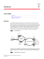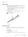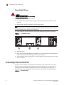
1
53-1002650-01
16 October 2012
Brocade 6910
Ethernet Access Switch
Hardware Installation Guide
®
Copyright © 2012 Brocade Communications Systems, Inc. All Rights Reserved.
Brocade, the B-wing symbol, BigIron, DCX, Fabric OS, FastIron, NetIron, SAN Health, ServerIron, and TurboIron are registered
trademarks, and Brocade Assurance, Brocade NET Health, Brocade One, CloudPlex, MLX, VCS, VDX, and When the Mission Is
Critical, the Network Is Brocade are trademarks of Brocade Communications Systems, Inc., in the United States and/or in other
countries. Other brands, products, or service names mentioned are or may be trademarks or service marks of their respective
owners.
Notice: This document is for informational purposes only and does not set forth any warranty, expressed or implied, concerning
any equipment, equipment feature, or service offered or to be offered by Brocade. Brocade reserves the right to make changes to
this document at any time, without notice, and assumes no responsibility for its use. This informational document describes
features that may not be currently available. Contact a Brocade sales office for information on feature and product availability.
Export of technical data contained in this document may require an export license from the United States government. The
authors and Brocade Communications Systems, Inc. shall have no liability or responsibility to any person or entity with respect to
any loss, cost, liability, or damages arising from the information contained in this book or the computer programs that accompany
it.
The product described by this document may contain “open source” software covered by the GNU General Public License or other
open source license agreements. To find out which open source software is included in Brocade products, view the licensing
terms applicable to the open source software, and obtain a copy of the programming source code, please visit
http://www.brocade.com/support/oscd.
Brocade Communications Systems, Incorporated
Corporate and Latin American Headquarters
Brocade Communications Systems, Inc.
130 Holger Way
San Jose, CA 95134
Tel: 1-408-333-8000
Fax: 1-408-333-8101
E-mail: [email protected]
Asia-Pacific Headquarters
Brocade Communications Systems China HK, Ltd.
No. 1 Guanghua Road
Chao Yang District
Units 2718 and 2818
Beijing 100020, China
Tel: +8610 6588 8888
Fax: +8610 6588 9999
E-mail: [email protected]
European Headquarters
Brocade Communications Switzerland Sàrl
Centre Swissair
Tour B - 4ème étage
29, Route de l'Aéroport
Case Postale 105
CH-1215 Genève 15
Switzerland
Tel: +41 22 799 5640
Fax: +41 22 799 5641
E-mail: [email protected]
Asia-Pacific Headquarters
Brocade Communications Systems Co., Ltd. (Shenzhen WFOE)
Citic Plaza
No. 233 Tian He Road North
Unit 1308 – 13th Floor
Guangzhou, China
Tel: +8620 3891 2000
Fax: +8620 3891 2111
E-mail: [email protected]
Document History
Title
Publication number
Summary of changes
Date
Brocade 6910 Ethernet Access Switch
Hardware Installation Guide
53-1002345-01
New document
December 2011
Brocade 6910 Ethernet Access Switch
Hardware Installation Guide
53-1002345-02
Updated package contents
January 2012
Brocade 6910 Ethernet Access Switch
Hardware Installation Guide
53-1002345-03
Updated Cautions and Dangers
appendices
February 2012
Brocade 6910 Ethernet Access Switch
Hardware Installation Guide
53-1002580-01
Updated formating
May 2012
Brocade 6910 Ethernet Access Switch
Hardware Installation Guide
53-1002650-01
Corrected standard temp range October 2012
Corrected Switching Database
specification to 16K MAC entries
Contents
About This Document
Audience . . . . . . . . . . . . . . . . . . . . . . . . . . . . . . . . . . . . . . . . . . . . . . . . xi
Supported hardware and software . . . . . . . . . . . . . . . . . . . . . . . . . . . xi
Document conventions . . . . . . . . . . . . . . . . . . . . . . . . . . . . . . . . . . . . . xi
Text formatting . . . . . . . . . . . . . . . . . . . . . . . . . . . . . . . . . . . . . . . . xi
Notes, cautions, and danger notices . . . . . . . . . . . . . . . . . . . . . xii
Related publications . . . . . . . . . . . . . . . . . . . . . . . . . . . . . . . . . . . . . . xii
Getting technical help or reporting errors . . . . . . . . . . . . . . . . . . . . . xiii
Chapter 1
Introduction
Overview . . . . . . . . . . . . . . . . . . . . . . . . . . . . . . . . . . . . . . . . . . . . . . . . 1
Switch Architecture . . . . . . . . . . . . . . . . . . . . . . . . . . . . . . . . . . . . 3
Network Management Options . . . . . . . . . . . . . . . . . . . . . . . . . . . . . . 3
Description of Hardware . . . . . . . . . . . . . . . . . . . . . . . . . . . . . . . . . . . . 4
SFP Slots. . . . . . . . . . . . . . . . . . . . . . . . . . . . . . . . . . . . . . . . . . . . . 4
10/100/1000BASE-T Ports . . . . . . . . . . . . . . . . . . . . . . . . . . . . . 5
10/100/1000BASE-T Management Port (The Craft Interface) . 5
Console Port . . . . . . . . . . . . . . . . . . . . . . . . . . . . . . . . . . . . . . . . . . 5
Alarm Interface Port. . . . . . . . . . . . . . . . . . . . . . . . . . . . . . . . . . . . 5
Port and System Status LEDs . . . . . . . . . . . . . . . . . . . . . . . . . . . . 5
Power Supply Sockets . . . . . . . . . . . . . . . . . . . . . . . . . . . . . . . . . . 7
Chapter 2
Installing the Switch
Selecting a Site . . . . . . . . . . . . . . . . . . . . . . . . . . . . . . . . . . . . . . . . . . . 9
Ethernet Cabling . . . . . . . . . . . . . . . . . . . . . . . . . . . . . . . . . . . . . . . . . 10
Equipment Checklist . . . . . . . . . . . . . . . . . . . . . . . . . . . . . . . . . . . . . . 10
Package Contents . . . . . . . . . . . . . . . . . . . . . . . . . . . . . . . . . . . . 10
Mounting . . . . . . . . . . . . . . . . . . . . . . . . . . . . . . . . . . . . . . . . . . . . . . . 11
Desktop or Shelf Mounting . . . . . . . . . . . . . . . . . . . . . . . . . . . . . 11
Rack Mounting . . . . . . . . . . . . . . . . . . . . . . . . . . . . . . . . . . . . . . . 11
Installing an Optional SFP Transceiver . . . . . . . . . . . . . . . . . . . . . . . 13
Grounding the Chassis . . . . . . . . . . . . . . . . . . . . . . . . . . . . . . . . . . . . 13
Connecting to a Power Source . . . . . . . . . . . . . . . . . . . . . . . . . . . . . . 14
Connecting DC Power . . . . . . . . . . . . . . . . . . . . . . . . . . . . . . . . . 14
Connecting AC Power . . . . . . . . . . . . . . . . . . . . . . . . . . . . . . . . . . 18
Connecting to the Console Port . . . . . . . . . . . . . . . . . . . . . . . . . . . . . 18
Wiring Map for Serial Cable. . . . . . . . . . . . . . . . . . . . . . . . . . . . . 19
Brocade 6910 Ethernet Access Switch Hardware Installation Guide
53-1002650-01
iii
Connecting to the Alarm Port . . . . . . . . . . . . . . . . . . . . . . . . . . . . . . .20
Wiring Map for Alarm Cable. . . . . . . . . . . . . . . . . . . . . . . . . . . . .20
Chapter 3
Making Network Connections
Connecting Network Devices . . . . . . . . . . . . . . . . . . . . . . . . . . . . . . .23
Twisted-Pair Devices . . . . . . . . . . . . . . . . . . . . . . . . . . . . . . . . . . . . . . 23
Cabling Guidelines . . . . . . . . . . . . . . . . . . . . . . . . . . . . . . . . . . . .23
Connecting to PCs, Servers, Hubs and Switches. . . . . . . . . . . .23
Fiber Optic Devices . . . . . . . . . . . . . . . . . . . . . . . . . . . . . . . . . . . . . . . 24
Appendix A
Troubleshooting
Diagnosing Switch Indicators . . . . . . . . . . . . . . . . . . . . . . . . . . . . . . .25
In-Band Access . . . . . . . . . . . . . . . . . . . . . . . . . . . . . . . . . . . . . . . . . .25
Appendix B
Cables
Twisted-Pair Cable and Pin Assignments. . . . . . . . . . . . . . . . . . . . . . 27
10BASE-T/100BASE-TX Pin Assignments. . . . . . . . . . . . . . . . . . 27
Straight-Through Wiring . . . . . . . . . . . . . . . . . . . . . . . . . . . . . . . .28
Crossover Wiring . . . . . . . . . . . . . . . . . . . . . . . . . . . . . . . . . . . . .28
1000BASE-T Pin Assignments. . . . . . . . . . . . . . . . . . . . . . . . . . . 29
Cable Testing for Existing Category 5 Cable. . . . . . . . . . . . . . . .29
Adjusting Existing Category 5 Cabling to Run 1000BASE-T . . .30
Fiber Standards . . . . . . . . . . . . . . . . . . . . . . . . . . . . . . . . . . . . . .30
Appendix C
Specifications
Physical Characteristics . . . . . . . . . . . . . . . . . . . . . . . . . . . . . . . . . . . 31
Ports . . . . . . . . . . . . . . . . . . . . . . . . . . . . . . . . . . . . . . . . . . . . . . . 31
Network Interface . . . . . . . . . . . . . . . . . . . . . . . . . . . . . . . . . . . . 31
Buffer Architecture. . . . . . . . . . . . . . . . . . . . . . . . . . . . . . . . . . . . 31
Aggregate Bandwidth. . . . . . . . . . . . . . . . . . . . . . . . . . . . . . . . . . 31
Switching Database . . . . . . . . . . . . . . . . . . . . . . . . . . . . . . . . . . . 31
LEDs . . . . . . . . . . . . . . . . . . . . . . . . . . . . . . . . . . . . . . . . . . . . . . . 31
Weight . . . . . . . . . . . . . . . . . . . . . . . . . . . . . . . . . . . . . . . . . . . . . . 31
Size . . . . . . . . . . . . . . . . . . . . . . . . . . . . . . . . . . . . . . . . . . . . . . . . 32
Temperature . . . . . . . . . . . . . . . . . . . . . . . . . . . . . . . . . . . . . . . . .32
Humidity . . . . . . . . . . . . . . . . . . . . . . . . . . . . . . . . . . . . . . . . . . . .32
AC Input . . . . . . . . . . . . . . . . . . . . . . . . . . . . . . . . . . . . . . . . . . . .32
DC Input . . . . . . . . . . . . . . . . . . . . . . . . . . . . . . . . . . . . . . . . . . . .32
Power Supply . . . . . . . . . . . . . . . . . . . . . . . . . . . . . . . . . . . . . . . .32
Power Consumption . . . . . . . . . . . . . . . . . . . . . . . . . . . . . . . . . . .32
Maximum Current . . . . . . . . . . . . . . . . . . . . . . . . . . . . . . . . . . . .32
Switch Features. . . . . . . . . . . . . . . . . . . . . . . . . . . . . . . . . . . . . . . . . .32
Forwarding Mode . . . . . . . . . . . . . . . . . . . . . . . . . . . . . . . . . . . . .32
Throughput . . . . . . . . . . . . . . . . . . . . . . . . . . . . . . . . . . . . . . . . . .33
Flow Control . . . . . . . . . . . . . . . . . . . . . . . . . . . . . . . . . . . . . . . . .33
iv
Brocade 6910 Ethernet Access Switch Hardware Installation Guide
53-1002650-01
Management Features . . . . . . . . . . . . . . . . . . . . . . . . . . . . . . . . . . . .33
In-Band Management . . . . . . . . . . . . . . . . . . . . . . . . . . . . . . . . .33
Out-of-Band Management . . . . . . . . . . . . . . . . . . . . . . . . . . . . . .33
Software Loading . . . . . . . . . . . . . . . . . . . . . . . . . . . . . . . . . . . . .33
Standards . . . . . . . . . . . . . . . . . . . . . . . . . . . . . . . . . . . . . . . . . . . . . .33
Compliances . . . . . . . . . . . . . . . . . . . . . . . . . . . . . . . . . . . . . . . . . . . .33
Emissions . . . . . . . . . . . . . . . . . . . . . . . . . . . . . . . . . . . . . . . . . . .33
Immunity. . . . . . . . . . . . . . . . . . . . . . . . . . . . . . . . . . . . . . . . . . . .34
Safety . . . . . . . . . . . . . . . . . . . . . . . . . . . . . . . . . . . . . . . . . . . . . .34
Appendix D
Caution and Danger Notices: English / French
Cautions. . . . . . . . . . . . . . . . . . . . . . . . . . . . . . . . . . . . . . . . . . . . . . . .35
Dangers . . . . . . . . . . . . . . . . . . . . . . . . . . . . . . . . . . . . . . . . . . . . . . . . 37
Appendix E
Caution and Danger Notices: German / Spanish / Chinese
Cautions. . . . . . . . . . . . . . . . . . . . . . . . . . . . . . . . . . . . . . . . . . . . . . . . 41
Dangers . . . . . . . . . . . . . . . . . . . . . . . . . . . . . . . . . . . . . . . . . . . . . . . .44
Spanish (only) . . . . . . . . . . . . . . . . . . . . . . . . . . . . . . . . . . . . . . . . . . .46
Chinese (Traditional) . . . . . . . . . . . . . . . . . . . . . . . . . . . . . . . . . . . . . .52
Taiwan BSMI Statement . . . . . . . . . . . . . . . . . . . . . . . . . . . . . . .60
Chinese (Simplified) . . . . . . . . . . . . . . . . . . . . . . . . . . . . . . . . . . . . . . 61
Appendix F
Glossary
Index
Brocade 6910 Ethernet Access Switch Hardware Installation Guide
53-1002650-01
v
vi
Brocade 6910 Ethernet Access Switch Hardware Installation Guide
53-1002650-01
Figures
Figure 1
GbE ACCESS RINGS . . . . . . . . . . . . . . . . . . . . . . . . . . . . . . . . . . . . . . . . . . . . . . . . . 1
Figure 2
FRONT PANEL Brocade 6910 Switch . . . . . . . . . . . . . . . . . . . . . . . . . . . . . . . . . . . 2
Figure 3
FRONT PANEL Brocade 6910 Switch . . . . . . . . . . . . . . . . . . . . . . . . . . . . . . . . . . . 2
Figure 4
SIDE PANEL . . . . . . . . . . . . . . . . . . . . . . . . . . . . . . . . . . . . . . . . . . . . . . . . . . . . . . . . 3
Figure 5
REAR PANEL . . . . . . . . . . . . . . . . . . . . . . . . . . . . . . . . . . . . . . . . . . . . . . . . . . . . . . . 3
Figure 6
PORT AND SYSTEM LEDs . . . . . . . . . . . . . . . . . . . . . . . . . . . . . . . . . . . . . . . . . . . . . 6
Figure 7
Brocade 6910 Switch - AC Power Supply Sockets . . . . . . . . . . . . . . . . . . . . . . . . . 7
Figure 8
Brocade 6910 Switch-DC Power Supply Sockets. . . . . . . . . . . . . . . . . . . . . . . . . . 7
Figure 9
RJ-45 CONNECTIONS . . . . . . . . . . . . . . . . . . . . . . . . . . . . . . . . . . . . . . . . . . . . . . . 10
Figure 10
ATTACHING THE ADHESIVE FEET. . . . . . . . . . . . . . . . . . . . . . . . . . . . . . . . . . . . . . 11
Figure 11
ATTACHING THE BRACKETS . . . . . . . . . . . . . . . . . . . . . . . . . . . . . . . . . . . . . . . . . . 12
Figure 12
INSTALLING THE SWITCH IN A RACK. . . . . . . . . . . . . . . . . . . . . . . . . . . . . . . . . . . 12
Figure 13
INSTALLING AN OPTIONAL SFP TRANSCEIVER . . . . . . . . . . . . . . . . . . . . . . . . . . . 13
Figure 14
GROUNDING POINT. . . . . . . . . . . . . . . . . . . . . . . . . . . . . . . . . . . . . . . . . . . . . . . . . 14
Figure 15
DC PLUG CONNECTIONS . . . . . . . . . . . . . . . . . . . . . . . . . . . . . . . . . . . . . . . . . . . . 16
Figure 16
DC PLUG CONNECTIONS 2. . . . . . . . . . . . . . . . . . . . . . . . . . . . . . . . . . . . . . . . . . . 17
Figure 17
AC POWER SOCKETS . . . . . . . . . . . . . . . . . . . . . . . . . . . . . . . . . . . . . . . . . . . . . . . 18
Figure 18
CONSOLE CABLE. . . . . . . . . . . . . . . . . . . . . . . . . . . . . . . . . . . . . . . . . . . . . . . . . . . 19
Figure 19
ALARM PORT (D-15) PIN OUT. . . . . . . . . . . . . . . . . . . . . . . . . . . . . . . . . . . . . . . . . 20
Figure 20
EXTERNAL ALARM I/O CONNNECTORS . . . . . . . . . . . . . . . . . . . . . . . . . . . . . . . . . 21
Figure 21
MAKING CONNECTIONS TO SFP TRANSCEIVERS . . . . . . . . . . . . . . . . . . . . . . . . . 24
Figure 22
RJ-45 CONNECTOR PIN NUMBERS . . . . . . . . . . . . . . . . . . . . . . . . . . . . . . . . . . . . 27
Figure 23
STRAIGHT-THROUGH WIRING . . . . . . . . . . . . . . . . . . . . . . . . . . . . . . . . . . . . . . . . 28
Figure 24
CROSSOVER WIRING . . . . . . . . . . . . . . . . . . . . . . . . . . . . . . . . . . . . . . . . . . . . . . . 29
Brocade 6910 Ethernet Access Switch Hardware Installation Guide
53-1002650-01
vii
viii
Brocade 6910 Ethernet Access Switch Hardware Installation Guide
53-1002650-01
Tables
Table 1
SYSTEM STATUS LEDs . . . . . . . . . . . . . . . . . . . . . . . . . . . . . . . . . . . . . . . . . . . . . . . 6
Table 2
1000 Mbps PORT STATUS / SFP LEDs (1~12). . . . . . . . . . . . . . . . . . . . . . . . . . . . 7
Table 3
SERIAL CABLE WIRING . . . . . . . . . . . . . . . . . . . . . . . . . . . . . . . . . . . . . . . . . . . . . . 19
Table 4
SYSTEM STATUS LEDs . . . . . . . . . . . . . . . . . . . . . . . . . . . . . . . . . . . . . . . . . . . . . . 20
Table 5
TROUBLESHOOTING CHART . . . . . . . . . . . . . . . . . . . . . . . . . . . . . . . . . . . . . . . . . . 25
Table 6
10/100BASE-TX MDI and MDI-X PORT PINOUTS . . . . . . . . . . . . . . . . . . . . . . . . . 28
Table 7
1000BASE-T MDI and MDI-X PORT PINOUTS . . . . . . . . . . . . . . . . . . . . . . . . . . . . 29
Table 8
FIBER STANDARDS . . . . . . . . . . . . . . . . . . . . . . . . . . . . . . . . . . . . . . . . . . . . . . . . . 30
Brocade 6910 Ethernet Access Switch Hardware Installation Guide
53-1002650-01
ix
x
Brocade 6910 Ethernet Access Switch Hardware Installation Guide
53-1002650-01
About This Document
In this chapter
• Audience. . . . . . . . . . . . . . . . . . . . . . . . . . . . . . . . . . . . . . . . . . . . . . . . . . . . . . . xi
• Supported hardware and software. . . . . . . . . . . . . . . . . . . . . . . . . . . . . . . . . . xi
• Document conventions . . . . . . . . . . . . . . . . . . . . . . . . . . . . . . . . . . . . . . . . . . . xi
• Related publications . . . . . . . . . . . . . . . . . . . . . . . . . . . . . . . . . . . . . . . . . . . . xii
• Related publications . . . . . . . . . . . . . . . . . . . . . . . . . . . . . . . . . . . . . . . . . . . . xii
• Getting technical help or reporting errors . . . . . . . . . . . . . . . . . . . . . . . . . . . xiii
Audience
This document is designed for system administrators with a working knowledge of Layer 2 and
Layer 3 switching and routing.
If you are using a Brocade Layer 3 Switch, you should be familiar with the following protocols if
applicable to your network: IP, RIP, OSPF, BGP, ISIS, IGMP, PIM, and VRRP.
Supported hardware and software
This guide describes software release 2.2.0.x of the Brocade 6910 Ethernet Access Switch.
Document conventions
This section describes text formatting conventions and important notice formats used in this
document.
Text formatting
The narrative-text formatting conventions that are used are as follows:
Brocade 6910 Ethernet Access Switch Hardware Installation Guide
53-1002650-01
xi
About This Document
bold text
Identifies command names
Identifies the names of user-manipulated GUI elements
Identifies keywords
Identifies text to enter at the GUI or CLI
italic text
Provides emphasis
Identifies variables
Identifies document titles
code text
Identifies CLI output
For readability, command names in the narrative portions of this guide are presented in bold: for
example, show version.
Notes, cautions, and danger notices
The following notices and statements are used in this manual. They are listed below in order of
increasing severity of potential hazards.
NOTE
A note provides a tip, guidance or advice, emphasizes important information, or provides a reference
to related information.
CAUTION
A Caution statement alerts you to situations that can be potentially hazardous to you or cause
damage to hardware, firmware, software, or data.
DANGER
A Danger statement indicates conditions or situations that can be potentially lethal or extremely
hazardous to you. Safety labels are also attached directly to products to warn of these conditions
or situations.
Related publications
The following Brocade documents supplement the information in this guide:
• Brocade 6910 Ethernet Access Switch Configuration Guide
• Brocade 6910 Ethernet Access Switch MIB Reference
• Brocade 6910 Ethernet Access Switch Diagnostic Guide
NOTE
For the latest edition of these documents, which contain the most up-to-date information, go to
http://www.brocade.com/ethernetproducts.
xii
Brocade 6910 Ethernet Access Switch Hardware Installation Guide
53-1002650-01
About This Document
Getting technical help or reporting errors
If you need assistance, contact Brocade. Go to
http://www.brocade.com/services-support/index.page for the latest e-mail and telephone contact
information.
Brocade 6910 Ethernet Access Switch Hardware Installation Guide
53-1002650-01
xiii
About This Document
xiv
Brocade 6910 Ethernet Access Switch Hardware Installation Guide
53-1002650-01
Chapter
1
Introduction
In this chapter
• Overview . . . . . . . . . . . . . . . . . . . . . . . . . . . . . . . . . . . . . . . . . . . . . . . . . . . . . . . 1
• Network Management Options. . . . . . . . . . . . . . . . . . . . . . . . . . . . . . . . . . . . . 3
• Description of Hardware . . . . . . . . . . . . . . . . . . . . . . . . . . . . . . . . . . . . . . . . . . 4
Overview
The Brocade 6910 Ethernet Access Switches are carrier grade access switches that meet the
requirements for nonstop networking with Layer 2 services. Each platform provides dual power
input for redundancy and has been architected with the state of the art hardware design and field
proven operating system for reliability and resiliency. Brocade 6910 switches support multiple fiber
or copper configurations on a single switch using a 12 Gigabit combination RJ-45/SFP ports.
Brocade 6910 allows the same ports to be configured to connect directly to the customer or as
network interface on the service side. This ideally positions the Brocade 6910 at the edge of a
broadband access network for Ethernet service demarcation, extension and aggregation.
FIGURE 1
GbE ACCESS RINGS
MLX
6910
GbE Access
Ring
6910
CES
6910
10G Regional Ring
IP/MPLS
6910
CES
MLX
The switches have a 1000BASE-T port for dedicated management access (which can be operated
outside the data channel). It has an SNMP-based management agent embedded on the main
board, which supports both in-band and out-of-band access using a Web browser, SNMP/RMON, or
Telnet.
FIGURE 2
FRONT PANEL Brocade 6910 Switch
Brocade 6910 Ethernet Access Switch Hardware Installation Guide
53-1002650-01
1
1
Overview
1
2
3
4
5
12
11
10
9
8
3
4
7
6
1. AC Input
2. Port Status LEDs
3. Minor Alarm LED
4. Major Alarm LED
5. Alarm Port
6. Diag LED
7.
Power LED
8. Mgmt LED
9. RJ-45 Console & Management Ports
10. Reset Button
11. Combination RJ-45/SFP Ports
12. Grounding Points
FIGURE 3
FRONT PANEL Brocade 6910 Switch
1
8
2
7
6
5
1. DC Input
2. Port Status LEDs
3. System Status LEDs
4. Alarm Port
5. RJ-45 Console & Management Ports
6. Reset Button
7.
Combination RJ-45/SFP Ports
8. Grounding Points
FIGURE 4
2
SIDE PANEL
Brocade 6910 Ethernet Access Switch Hardware Installation Guide
53-1002650-01
1
Network Management Options
1
1. Ventilation
FIGURE 5
REAR PANEL
1
1. Ventilation
Switch Architecture
These switches employ a wire-speed, non-blocking switching fabric. This permits simultaneous
wire-speed transport of multiple packets at low latency on all ports.
Network Management Options
These switches contain a comprehensive array of LEDs for “at-a-glance” monitoring of network and
port status. They also include a management agent that allows you to configure or monitor the
switch using its embedded management software, or through SNMP applications. To manage the
switch, you can make a direct connection to the console port (out-of-band), or you can manage the
switch through a network connection (in-band) using Telnet, SSH, the on-board web agent, or
SNMP-based network management software.
The switch management port (RJ-45) provides a dedicated management channel that operates
outside of the data transport network. This makes it possible to re-configure or troubleshoot the
switch over either a local or remote connection to the port when access through the data channel is
not possible or deemed insecure.
For a detailed description of the switch’s advanced features, refer to the Brocade 6910 Ethernet
Access Switch Configuration Guide.
Brocade 6910 Ethernet Access Switch Hardware Installation Guide
53-1002650-01
3
1
Description of Hardware
Description of Hardware
The Brocade 6910 switches consist of two model types, one hardened for extended temperature
range environments, the other non-hardened for standard temperature range environments:
• Standard temperature range switches for 0 to +55 °C:
• BR-6910-EA-AC
• BR-6910-EA-DC
• Extended temperature range switches for -40 to +65 °C:
• BR-6910-EA-H-AC
• BR-6910-EA-H-DC
SFP Slots
The 12 Small Form Factor Pluggable (SFP) transceiver slots are shared with 12 RJ-45 ports. In its
default configuration, if an SFP transceiver (purchased separately) is installed in a slot and has a
valid link on its port, the associated RJ-45 port is disabled and cannot be used. The switch can also
be configured to force the use of an RJ-45 port or SFP slot, as required.
There are two types of SPF transceivers - one hardened that can operate at temperatures between
-40 to +65 °C, and non-hardened that can operate at temperatures between 0 to +55 °C.
The SFP slots support the following SFP transceivers:
• Standard temperature range optics (0 to +55 °C)
• 100Base-FX-IR
• 100Base-FX-LR
• 1000Base-SX (OM) 33210-100
• 1000Base-LX (OM) 33211-100
• 1000Base-LHA (OM) 33212-100
• 1000Base-LHB 33004-000
• 1000Base-BXU 33006-000
• 1000Base-BXD 33005-000
• 1000Base-CWDM
• Extended temperature range optics (-40 to +65 °C)
• 1000Base-SX (OM)
• 1000Base-LX (OM)
• 1000Base-LHA (OM)
For information on the recommended standards for fiber optic cabling, see “Fiber Optic Devices”
on page 24.
4
Brocade 6910 Ethernet Access Switch Hardware Installation Guide
53-1002650-01
1
Description of Hardware
10/100/1000BASE-T Ports
The switches contain 12 1000BASE-T RJ-45 ports that operate at 10 Mbps or 100 Mbps, half or full
duplex, or at 1000 Mbps, full duplex. Because all of the RJ-45 ports support automatic MDI/MDI-X
operation, you can use straight-through cables for all network connections to PCs or servers, or to
other switches or hubs. (See “1000BASE-T Pin Assignments” on page 29.)
Each of these ports support auto-negotiation, so the optimum transmission mode (half or full
duplex), and data rate (10, 100 or 1000 Mbps) can be selected automatically. If a device
connected to one of these ports does not support auto-negotiation, the communication mode of
that port can be configured manually. Each port also supports auto-negotiation of flow control, so
the switch can automatically prevent port buffers from becoming saturated.
10/100/1000BASE-T Management Port (The Craft Interface)
The 10/100/1000BASE-T port provides a dedicated management interface that is segregated
from the data traffic crossing the other ports. This port supports auto-negotiation, so the optimum
transmission mode (half or full duplex) and data rate (10, 100, or 1000 Mbps) can be selected
automatically, if this feature is also supported by the attached device. However, note that the
interface connection parameters of this port cannot be configured.
Console Port
The console port on the switch’s front panel is an RJ-45 connector that enables a connection to a
terminal for performing switch monitoring and configuration functions. The terminal may be a PC or
workstation running terminal emulation software, or a terminal configured as a Data Terminal
Equipment (DTE) connection. A null-modem wired serial cable is supplied with the switch for
connecting to this interface.
It is recommended that you use the cable provided with the box.
Flow control must be disabled to use the console port and port speed is 9600-N-8-1
Alarm Interface Port
The DB-15 alarm port on the switch’s front panel can be used to provide alarm, service port, and
BITS clock reference interfaces. The switch supports two sets of alarm relay contacts (major and
minor), and 4 external customer site alarm inputs. It also provides an alarm cutoff button (labeled
ACO). Refer to “Connecting to the Alarm Port” on page 20 for a description of the pin assignments
used to connect to the alarm port.
Port and System Status LEDs
This switch includes a display panel for key system and port indications that simplifies installation
and troubleshooting. The LEDs, which are located on the front panel for easy viewing, are shown
below and described in the following tables.
FIGURE 6
PORT AND SYSTEM LEDs
Brocade 6910 Ethernet Access Switch Hardware Installation Guide
53-1002650-01
5
1
Description of Hardware
1
1
9
1
10
1
11
2
3
12
4
5
6
1. Port Status LEDs
2. Major Alarm LED
3. Minor Alarm LED
4. Diag LED
5. Power LED
6. Mgmt LED
TABLE 1
LED
Condition
Status
Major Alarm
Green
Indicates presence within the system of one or more major
traffic-affecting system alarm(s) that are not masked by the
alarm filter.
Off
System is operating normally.
Green
Indicates presence within the system of one or more minor
traffic-affecting system alarm(s) that are not masked by the
alarm filter.
Off
System is operating normally.
Amber
System self-diagnostic is in progress.
Green
System self-diagnostic test successfully completed.
Green
The management port has a valid 1000BASE-T link.
Flashing Green
Flashing indicates 1000BASE-T activity on the port.
Amber
The management port has a valid 10/100BASE-TX link.
Flashing Amber
Flashing indicates 10/100BASE-TX activity on the port.
Off
The link is down.
Green
DC or AC power is functioning normally.
Off
External power not connected or has failed.
Minor Alarm
Diag
Mgmt
Power
6
SYSTEM STATUS LEDs
Brocade 6910 Ethernet Access Switch Hardware Installation Guide
53-1002650-01
1
Description of Hardware
TABLE 2
1000 Mbps PORT STATUS / SFP LEDs (1~12)
LED
Condition
Status
Port Status (1~12)
On/Flashing Green
Port has established a valid 1000 Mbps network connection.
Flashing indicates activity.
On/Flashing Amber
Port has established a valid 10/100 Mbps network
connection. Flashing indicates activity.
Off
There is no valid link on the port.
Power Supply Sockets
There are two power sockets on the front panel of each switch, as well as two grounding points for
each power supply inlets.
FIGURE 7
Brocade 6910 Switch - AC Power Supply Sockets
2
1
1
1. AC Power Socket
2. Grounding Points
FIGURE 8
Brocade 6910 Switch-DC Power Supply Sockets
1
2
1. DC Power Socket
2. Grounding Points
Brocade 6910 Ethernet Access Switch Hardware Installation Guide
53-1002650-01
7
1
8
Description of Hardware
Brocade 6910 Ethernet Access Switch Hardware Installation Guide
53-1002650-01
Chapter
Installing the Switch
2
CAUTION
Procedures are for qualified service personnel only.
In this chapter
• Selecting a Site . . . . . . . . . . . . . . . . . . . . . . . . . . . . . . . . . . . . . . . . . . . . . . . . . 9
• Ethernet Cabling . . . . . . . . . . . . . . . . . . . . . . . . . . . . . . . . . . . . . . . . . . . . . . . 10
• Equipment Checklist . . . . . . . . . . . . . . . . . . . . . . . . . . . . . . . . . . . . . . . . . . . . 10
• Mounting . . . . . . . . . . . . . . . . . . . . . . . . . . . . . . . . . . . . . . . . . . . . . . . . . . . . . 11
• Installing an Optional SFP Transceiver. . . . . . . . . . . . . . . . . . . . . . . . . . . . . . 12
• Grounding the Chassis . . . . . . . . . . . . . . . . . . . . . . . . . . . . . . . . . . . . . . . . . . 13
• Connecting to a Power Source . . . . . . . . . . . . . . . . . . . . . . . . . . . . . . . . . . . . 14
• Connecting to the Console Port . . . . . . . . . . . . . . . . . . . . . . . . . . . . . . . . . . . 18
• Connecting to the Alarm Port . . . . . . . . . . . . . . . . . . . . . . . . . . . . . . . . . . . . . 20
Selecting a Site
Switch units can be mounted in a standard 19-inch equipment rack or on a flat surface. Be sure to
follow the guidelines below when choosing a location.
• The site should:
• be at the center of all the devices you want to link and near a power outlet.
• be able to maintain its temperature within -40 to 65 °C (-40 to 149°F) and its humidity
within 10% to 90%, non-condensing
• provide adequate space (approximately two inches) on all sides for proper air flow
• be accessible for installing, cabling and maintaining the devices
• allow the status LEDs to be clearly visible
• Make sure twisted-pair cable is always routed away from power lines, fluorescent lighting
fixtures and other sources of electrical interference, such as radios and transmitters.
• Make sure that the unit is connected to a separate grounded power outlet that provides 100 to
240 VAC, 50 to 60 Hz, is within 2 m (6.6 feet) of each device and is powered from an
independent circuit breaker. As with any equipment, using a filter or surge suppressor is
recommended.
Brocade 6910 Ethernet Access Switch Hardware Installation Guide
53-1002650-01
9
2
Ethernet Cabling
Ethernet Cabling
To ensure proper operation when installing the switch into a network, make sure that the current
cables are suitable for 10BASE-T, 100BASE-TX or 1000BASE-T operation. Check the following
criteria against the current installation of your network:
• Cable type: Unshielded twisted pair (UTP) or shielded twisted pair (STP) cables with RJ-45
connectors; Category 3 or better for 10BASE-T, Category 5 or better for 100BASE-TX, and
Category 5, 5e or 6 for 1000BASE-T.
• Protection from radio frequency interference emissions
• Electrical surge suppression
• Separation of electrical wires (switch related or other) and electromagnetic fields from data
based network wiring
• Safe connections with no damaged cables, connectors or shields
FIGURE 9
RJ-45 CONNECTIONS
1
1. RJ-45 Connector
Equipment Checklist
After unpacking this switch, check the contents to be sure you have received all the components.
Then, before beginning the installation, be sure you have all other necessary installation
equipment.
Package Contents
• Brocade Brocade 6910 Ethernet Access Switch switch
• Four adhesive foot pads
• Bracket Mounting Kit containing two brackets and eight screws for attaching the brackets to
the switch
10
Brocade 6910 Ethernet Access Switch Hardware Installation Guide
53-1002650-01
2
Mounting
• Console cable (RJ-45 to DB-9)
Mounting
The switch can be mounted on a desktop, shelf, or rack mounted. Mounting instructions follow.
Desktop or Shelf Mounting
1. Attach the four adhesive feet to the bottom of the first switch.
FIGURE 10
ATTACHING THE ADHESIVE FEET
2. Set the device on a flat surface near a power source, making sure there are at least two inches
of space on all sides for proper air flow.
3. If installing a single switch only, go to “Grounding the Chassis” on page 13.
4. If installing multiple switches, attach four adhesive feet to each one. Place each device
squarely on top of the one below, in any order.
Rack Mounting
Before rack mounting the switch, pay particular attention to the following factors:
• Temperature: Since the temperature within a rack assembly may be higher than the ambient
room temperature, check that the rack-environment temperature is within the specified
operating temperature range. Also be sure to leave adequate space around the ventilation
holes in the switch.
• Mechanical Loading: Do not place any equipment on top of a rack-mounted unit.
• Circuit Overloading: Be sure that the supply circuit to the rack assembly is not overloaded.
• Grounding: Rack-mounted equipment should be properly grounded. Particular attention should
be given to supply connections other than direct connections to the mains.
To rack-mount devices:
1. Attach the brackets to the device using the screws provided in the Bracket Mounting Kit.
FIGURE 11
ATTACHING THE BRACKETS
Brocade 6910 Ethernet Access Switch Hardware Installation Guide
53-1002650-01
11
2
Installing an Optional SFP Transceiver
2. Mount the device in the rack, using four rack-mounting screws (not provided).
FIGURE 12
INSTALLING THE SWITCH IN A RACK
Installing an Optional SFP Transceiver
FIGURE 13
12
INSTALLING AN OPTIONAL SFP TRANSCEIVER
Brocade 6910 Ethernet Access Switch Hardware Installation Guide
53-1002650-01
2
Grounding the Chassis
These switches support SFP-compatible transceivers. To install an SFP transceiver, do the
following:
1. Consider network and cabling requirements to select an appropriate SFP transceiver type.
2. Insert the transceiver with the optical connector facing outward and the slot connector facing
down. Note that SFP transceivers are keyed so they can only be installed in one orientation.
3. Slide the SFP transceiver into the slot until it clicks into place.
NOTE
SFP transceivers are hot-swappable. The switch does not need to be powered off before installing
or removing a transceiver. However, always first disconnect the network cable before removing a
transceiver.
NOTE
SFP transceivers are not provided in the switch package.
Grounding the Chassis
Before powering on the switch, ground the switch to earth as described below.
1. Ensure that the rack on which the switch is to be mounted is properly grounded and in
compliance with ETSI ETS 300 253.
2. Ensure that there is a good electrical connection to the grounding point on the rack (no paint or
isolating surface treatment).
3. Disconnect all power cables to the switch.
4. The switch chassis is connected internaly to 0 V. This circuit is connected to the grounding
terminal on the front of the switch. The surface area around this terminal is not painted in
order to provide for a good connection. Attach a 18 AWG stranded copper wire to the grounding
terminal on the switch.
5. Then attach the grounding wire to the ground point on the rack.
FIGURE 14
GROUNDING POINT
Brocade 6910 Ethernet Access Switch Hardware Installation Guide
53-1002650-01
13
2
Connecting to a Power Source
1
2
1. Attach an insulated grounding wire, with a metal screw, to the marked grounding point.
2. Terminate the wire in an earthed grounding point.
CAUTION
The earth connection must not be removed unless all supply connections have been
disconnected.
Connecting to a Power Source
These switches support either AC or DC only dual power supplies.
DANGER
Before wiring the DC plug or connecting power to the switch, ensure that power to the feed lines
is turned off at the supply circuit breaker or disconnected from the power bus
Connecting DC Power
When using 20-60Vdc power, an external DC power supply must be connected to the DC power
connector on the left side of the front panel. DC input (DC source) must be isolated from AC mains
by reinforced insulation.
DANGER
Remove both power cords before servicing.
NOTE
To provide adequate circuit protection between the DC power supply and the switch, all intermediate
wiring and circuitry should be rated to carry a load at least two times the maximum rating for this
switch (see “Power Supply” on page 32.)
NOTE
For a DC system, use a grounding wire of at least 18 American Wire Gauge (AWG). The 18 AWG wire
should be attached to an agency-approved crimp connector (provided on the chassis), and crimped
with the proper tool. The crimp connector should allow for securement to a ground screw on the
enclosure.
14
Brocade 6910 Ethernet Access Switch Hardware Installation Guide
53-1002650-01
Connecting to a Power Source
2
NOTE
Wiring for the power input terminals on the switch are described below. Wiring of the DC power
supply terminals depends on the equipment in use on the local site, but should be wired in such a
way as to meet the input requirements shown in “DC PLUG CONNECTIONS” on page 15. The wiring
should also be color coded according to local standards to ensure that the input power and ground
lines can be easily distinguished.
To connect the switch to a power source:
1. First verify that the DC power can provide 20-60Vdc, 1.9A.
2. Prepare two wires for each power source to be used. Use 18 AWG stranded copper wire. Make
sure these wires are not plugged into the power source.
3. Use a wire stripper to carefully strip about a half an inch of the outer insulation off the end of
each wire, exposing the copper core.
4. Twist the copper wire strands together to form a tight braid. If possible, solder the exposed
braid of wire together for better conductivity.
5. Connect the external power feed and power ground/return lines to the DC plug (provided with
the switch) as shown in the following figure. The plugs are labeled on the front of the chassis,
above the DC power connection block. The -48 VDC power feed uses the “-48VDC” input lines.
Use a small flat-tip screwdriver to loosen the screws on the power plug and open the wire
clamps.
This equipment installation must meet NEC/CEC code requirements. Consult local authorities for
regulations.
FIGURE 15
DC PLUG CONNECTIONS
Brocade 6910 Ethernet Access Switch Hardware Installation Guide
53-1002650-01
15
2
Connecting to a Power Source
Top View
2
1
3
4
Front View
Rear View
5
6
1. To switch
2. DC power ground / return
3. -48 VDC power feed
4. Screw-down connector
5. Screw into DC tapped hole on switch
6. DC power line in
FIGURE 16
16
DC PLUG CONNECTIONS 2
Brocade 6910 Ethernet Access Switch Hardware Installation Guide
53-1002650-01
2
Connecting to a Power Source
1
2
1. To Switch
2
DC power lines in
7.
Insert the wire leads into the openings shown in the figure below. Each lead inserted in the
power plug must match the lead attached to the power source. Use the label above the DC
power connection block to identify the appropriate power input and return or ground lines.
CAUTION
If the power leads are plugged into the wrong holes, the power supply will not work properly and
may damage the switch.
8. Push each wire about half an inch into the opening on the plug, and tighten down the clamp
screw securely. You should not be able to pull on the wire and dislodge it.
9. Insert the power plug in the power receptacle on the left side of the front panel.
10. At the power source, turn on the power for the feed lines or power bus.
11. Check the Power LED indicator as the switch is powered on. If not, recheck the power supply
and power cable connections at the supply source and at power conversion module.
12. To disconnect DC power from the switch, turn off the DC power feed lines before removing the
plugs from the DC sockets.
Brocade 6910 Ethernet Access Switch Hardware Installation Guide
53-1002650-01
17
2
Connecting to the Console Port
Connecting AC Power
DANGER
Remove both power cords before servicing.
To connect the switch to an AC power source:
1. First verify that the external AC power supply can provide 100 to 240 VAC, 50-60 Hz, 0.8 A
minimum.
2. Plug the power cable into a grounded, 3-pin, AC power source.
NOTE
For international use, you may need to change the AC line cord. You must use a line cord set that
has been approved for the socket type in your country.
3. Insert the plug on the other end of the power cable directly into the socket on the switch.
FIGURE 17
AC POWER SOCKETS
1.
1
AC Power Inlet
2.
Grounding Points
2
1
4. Check that the Power LED indicator on the switch is on. If not, recheck the power supply and
power cable connections at the supply source and at the switch.
5. To disconnect AC power from the switch, remove the plugs from the AC sockets on the left side
of the front panel.
Connecting to the Console Port
This port is used to connect a console device to the switch through a serial cable. The console
device can be a PC or workstation running a VT-100 terminal emulator, or a VT-100 terminal. A
crossover RJ-45 to DB-9 cable is supplied with the unit for connecting to the console port, as
illustrated below. The pin assignments used to connect to the serial port are described below.
FIGURE 18
18
CONSOLE CABLE
Brocade 6910 Ethernet Access Switch Hardware Installation Guide
53-1002650-01
2
Connecting to the Console Port
3
1
2
1. DB-9 Port
2. RJ-45 Connector
3. RJ-45 Port
Wiring Map for Serial Cable
TABLE 3
SERIAL CABLE WIRING
Switch’s 8-Pin Serial Port
Null Modem
PC’s 9-Pin DTE Port
6 RXD (receive data)
<------ --- --- --- --- --- --- --- --
3 TXD (transmit data)
3 TXD (transmit data)
--- ------- --- --- --- --- --- --- -->
2 RXD (receive data)
5 SGND (signal ground)
--- ---- --- --- --- --- --- --- --- ---
5 SGND (signal ground)
The serial port’s configuration requirements are as follows:
•
•
•
•
•
•
Default Baud rate—9600 bps
Character Size—8 Characters
Parity—None
Stop bit—One
Data bits—8
Flow control—none
Brocade 6910 Ethernet Access Switch Hardware Installation Guide
53-1002650-01
19
2
Connecting to the Alarm Port
Connecting to the Alarm Port
The DB-15 alarm port on the switch’s front panel is used to provide alarm. The switch supports two
sets of alarm relay contacts (major and minor), and 4 external customer site alarm inputs. The pin
assignments used to connect to the alarm port are provided in the following table.
FIGURE 19
ALARM PORT (D-15) PIN OUT
1
15
Wiring Map for Alarm Cable
The signals include relay contacts for major and minor system alarms, and external alarm inputs.
TABLE 4
SYSTEM STATUS LEDs
Switch’s Alarm Port
Funtion
1 (MJR_ALARM_CNTR)
Common contact for major alarm relay.
2 (MNR_ALARM_CNTR)
Common contact for minor alarm relay.
3 (ALARM_IN3_EXT_P*)
External alarm input 3 (external relay dry contact closure to pin 13).
4 (ALARM_IN4_EXT_P)
External alarm input 4 (external relay dry contact closure to pin 8).
5 (No Contact)
6 (MJR_ALARM_NO)
Normally open during major alarm state.
7 (MNR_ALARM_NO)
Normally open during minor alarm state.
8 (ALARM_IN4_EXT_RTN†)
External alarm input 4 (external relay dry contact closure from pin 3).
9 (ALARM_IN1_EXT_P)
External alarm input 1 (external relay dry contact closure to pin14).
10 (ALARM_IN2_EXT_P)
External alarm input 2 (external relay dry contact closure to pin 15).
11 (MJR_ALARM_NC)
Normally closed during major alarm state.
12 (MNR_ALARM_NC)
Normally closed during minor alarm state.
13 (ALARM_IN3_EXT_RTN)
External alarm input 3 (external relay dry contact closure from pin 3).
14 (ALARM_IN1_EXT_RTN)
External alarm input 1 (external relay dry contact closure from pin 9).
15 (ALARM_IN2_EXT_RTN)
External alarm input 2 (external relay dry contact closure from pin 10).
* P indicates positive input.
† RTN indicates return to Ground.
20
Brocade 6910 Ethernet Access Switch Hardware Installation Guide
53-1002650-01
2
Connecting to the Alarm Port
The following figure shows the pinout information for the DB-15 ALARM connector on the front
panel.
FIGURE 20
EXTERNAL ALARM I/O CONNNECTORS
Alarm
Connector
1
NC
11
COM
6
NO
Major Alarm
2
NC
12
COM
7
NO
9
10
3
4
External Alarm Input 1
External Alarm Input 2
External Alarm Input 3
External Alarm Input 4
Brocade 6910 Ethernet Access Switch Hardware Installation Guide
53-1002650-01
Minor Alarm
To backplane via internal signal
converter circuits.
External input uses dry relay contact
to pins 14, 15, 13 and 8 for grounding.
For active alarm, the relay is closed.
21
2
22
Connecting to the Alarm Port
Brocade 6910 Ethernet Access Switch Hardware Installation Guide
53-1002650-01
Chapter
Making Network Connections
3
In this chapter
• Connecting Network Devices . . . . . . . . . . . . . . . . . . . . . . . . . . . . . . . . . . . . . 23
• Twisted-Pair Devices . . . . . . . . . . . . . . . . . . . . . . . . . . . . . . . . . . . . . . . . . . . . 23
• Fiber Optic Devices . . . . . . . . . . . . . . . . . . . . . . . . . . . . . . . . . . . . . . . . . . . . . 24
Connecting Network Devices
These switches are designed to connect broadband access network devices to aggregation
network devices in the service provider CO. It can connect to twisted-pair devices through its RJ-45
ports, or to fiber-optic devices through SFP transceivers.
Twisted-Pair Devices
Each device requires an unshielded twisted-pair (UTP) cable with RJ-45 connectors at both ends.
Use Category 5, 5e or 6 cable for 1000BASE-T connections.
Cabling Guidelines
The RJ-45 ports on the switch support automatic MDI/MDI-X pinout configuration, so you can use
standard straight-through twisted-pair cables to connect to any other network device (PCs, servers,
switches, routers, or hubs). See “Twisted-Pair Cable and Pin Assignments” on page 27 for further
information on cabling.
CAUTION
Do not plug a phone jack connector into an RJ-45 port. This will damage the switch. Use only
twisted-pair cables with RJ-45 connectors that conform to FCC standards.
Connecting to PCs, Servers, Hubs and Switches
1. Attach one end of a twisted-pair cable segment to the device’s RJ-45 connector.
2. Attach the other end to an available port on the switch.
3. Make sure each twisted pair cable does not exceed 100 meters (328 ft) in length.
4. As each connection is made, the relevant Port LED (on the switch) corresponding to each port
will light green or amber to indicate that the connection is valid.
Brocade 6910 Ethernet Access Switch Hardware Installation Guide
53-1002650-01
23
3
Fiber Optic Devices
Fiber Optic Devices
An optional Gigabit SFP transceiver or 100BASE-FX SFP transceiver can be used for a backbone
connection between switches, or for connecting to a high-speed server.
Each single-mode fiber port requires 9/125 micron single-mode fiber optic cable with an LC
connector at both ends. Each multimode fiber optic port requires 50/125 or 62.5/125 micron
multimode fiber optic cabling with an LC connector at both ends.
CAUTION
This switch uses lasers to transmit signals over fiber optic cable. The lasers are compliant with
the requirements of a Class 1 Laser Product and are inherently eye safe in normal operation.
However, you should never look directly at a transmit port when it is powered on.
NOTE
When selecting a fiber SFP device, considering safety, please make sure that it can function at a
temperature that is not less than the recommended maximum operational temperature of the
product. You must also use an approved Laser Class 1 SFP transceiver.
1. Remove and keep the LC port’s rubber cover. When not connected to a fiber cable, the rubber
cover should be replaced to protect the optics.
2. Check that the fiber terminators are clean. You can clean the cable plugs by wiping them gently
with a clean tissue or cotton ball moistened with a little ethanol. Dirty fiber terminators on fiber
cables will impair the quality of the light transmitted through the cable and lead to degraded
performance on the port.
3. Connect one end of the cable to the LC port on the switch and the other end to the LC port on
the other device. Since LC connectors are keyed, the cable can be attached in only one
orientation.
FIGURE 21
MAKING CONNECTIONS TO SFP TRANSCEIVERS
4. As a connection is made, check the Link LED on the switch corresponding to the port to be
sure that the connection is valid.
24
Brocade 6910 Ethernet Access Switch Hardware Installation Guide
53-1002650-01
Appendix
A
Troubleshooting
Diagnosing Switch Indicators
TABLE 5
TROUBLESHOOTING CHART
Symptom
Action
Power LED is Off
•
•
•
•
•
Port LED is Off
•
•
Diag LED is Flashing
Amber
Mgmt LED is off
•
•
•
•
•
•
Major LED is Green
Minor LED is Green
•
•
•
•
Check connections between the switch, the power cord and the wall outlet.
Check if the port is disabled.
Verify that the switch and attached device are powered on.
Be sure the cable is plugged into both the switch and corresponding device.
If the switch is installed in a rack, check the connections to the punch-down
block and patch panel.
Verify that the proper cable type is used and its length does not exceed specified
limits.
Check the adapter on the attached device and cable connections for possible
defects. Replace the defective adapter or cable if necessary.
Power cycle the switch to try and clear the condition.
If the condition does not clear, contact your local dealer for assistance
Verify that the switch and attached device are powered on.
Be sure the cable is plugged into both the switch and corresponding device.
Verify that the proper cable type is used and its length does not exceed specified
limits.
Check the adapter on the attached device and cable connections for possible
defects. Replace the defective adapter or cable if necessary.
One or more major system alarm(s) affecting traffic have occurred.
Check the alarm filter mask to determine potential cause(s) of alarm.
One or more minor system alarm(s) affecting traffic have occurred.
Check the alarm filter mask to determine potential cause(s) of alarm.
In-Band Access
You can access the management agent in the switch from anywhere within the attached network
using Telnet, a Web browser, or other network management software tools. However, you must first
configure the switch with a valid IP address, subnet mask, and default gateway. If you have trouble
establishing a link to the management agent, check to see if you have a valid network connection.
Then verify that you entered the correct IP address. Also, be sure the port through which you are
connecting to the switch has not been disabled. If it has not been disabled, then check the network
cabling that runs between your remote location and the switch.
Brocade 6910 Ethernet Access Switch Hardware Installation Guide
53-1002650-01
25
A
In-Band Access
NOTE
The management agent can accept up to eight simultaneous Telnet sessions. If the maximum
number of sessions already exists, an additional Telnet connection will not be able to log into the
system.
26
Brocade 6910 Ethernet Access Switch Hardware Installation Guide
53-1002650-01
Appendix
B
Cables
Twisted-Pair Cable and Pin Assignments
For 10/100BASE-TX connections, the twisted-pair cable must have two pairs of wires. For
1000BASE-T connections the twisted-pair cable must have four pairs of wires. Each wire pair is
identified by two different colors. For example, one wire might be green and the other, green with
white stripes. Also, an RJ-45 connector must be attached to both ends of the cable.
CAUTION
DO NOT plug a phone jack connector into any RJ-45 port. Use only twisted-pair cables with RJ-45
connectors that conform with FCC standards.
CAUTION
Caution: Each wire pair must be attached to the RJ-45 connectors in a specific orientation.
The figure below illustrates how the pins on the RJ-45 connector are numbered. Be sure to hold the
connectors in the same orientation when attaching the wires to the pins.
FIGURE 22
RJ-45 CONNECTOR PIN NUMBERS
8
1
8
1
10BASE-T/100BASE-TX Pin Assignments
Use unshielded twisted-pair (UTP) or shielded twisted-pair (STP) cable for RJ-45 connections:
100-ohm Category 3 or better cable for 10 Mbps connections, or 100-ohm Category 5 or better
cable for 100 Mbps connections. Also be sure that the length of any twisted-pair connection does
not exceed 100 meters (328 feet).
The RJ-45 ports on the switch base unit support automatic MDI/MDI-X operation, so you can use
straight-through cables for all network connections to PCs or servers, or to other switches or hubs.
In straight-through cable, pins 1, 2, 3, and 6, at one end of the cable, are connected straight
through to pins 1, 2, 3, and 6 at the other end of the cable. When using any RJ-45 port on this
switch, you can use either straight-through or crossover cable.
Brocade 6910 Ethernet Access Switch Hardware Installation Guide
53-1002650-01
27
B
Twisted-Pair Cable and Pin Assignments
TABLE 6
10/100BASE-TX MDI and MDI-X PORT PINOUTS
Pin
MDI Signal Name
MDI-X Signal Name
1
Transmit Data plus (TD+)
Receive Data plus (RD+)
2
Transmit Data minus (TD-)
Receive Data minus (RD-)
3
Receive Data plus (RD+)
Transmit Data plus (TD+)
6
Receive Data minus (RD-)
Transmit Data minus (TD-)
4,5,7,8
Not used
Not used
NOTE
The “+” and “-” signs represent the polarity of the wires that make up each wire pair.
Straight-Through Wiring
If the twisted-pair cable is to join two ports and only one of the ports has an internal crossover
(MDI-X), the two pairs of wires must be straight-through. (When auto-negotiation is enabled for any
RJ-45 port on this switch, you can use either straight-through or crossover cable to connect to any
device type.)
You must connect all four wire pairs as shown in the following diagram to support Gigabit Ethernet.
FIGURE 23
STRAIGHT-THROUGH WIRING
EIA/TIA 568B RJ-45 Wiring Standard
10/100BASE-TX Straight-through Cable
White/Orange Stripe
Orange
End A
1
2
3
4
5
6
7
8
White/Green Stripe
Blue
White/Blue Stripe
Green
White/Brown Stripe
1
2
3
4
5
6
7
8
End B
Brown
Crossover Wiring
If the twisted-pair cable is to join two ports and either both ports are labeled with an “X” (MDI-X) or
neither port is labeled with an “X” (MDI), a crossover must be implemented in the wiring. (When
auto-negotiation is enabled for any RJ-45 port on this switch, you can use either straight-through or
crossover cable to connect to any device type.)
You must connect all four wire pairs as shown in the following diagram to support Gigabit Ethernet.
FIGURE 24
28
CROSSOVER WIRING
Brocade 6910 Ethernet Access Switch Hardware Installation Guide
53-1002650-01
B
Twisted-Pair Cable and Pin Assignments
EIA/TIA 568B RJ-45 Wiring Standard
10/100BASE-TX Crossover Cable
White/Orange Stripe
Orange
End A
White/Green Stripe
1
2
3
4
5
6
7
8
Blue
White/Blue Stripe
Green
White/Brown Stripe
1
2
3
4
5
6
7
8
End B
Brown
1000BASE-T Pin Assignments
All 1000BASE-T ports support automatic MDI/MDI-X operation, so you can use straight-through
cables for all network connections to PCs or servers, or to other switches or hubs.
The table below shows the 1000BASE-T MDI and MDI-X port pinouts. These ports require that all
four pairs of wires be connected. Note that for 1000BASE-T operation, all four pairs of wires are
used for both transmit and receive.
Use 100-ohm Category 5, 5e or 6 unshielded twisted-pair (UTP) or shielded twisted-pair (STP) cable
for 1000BASE-T connections. Also be sure that the length of any twisted-pair connection does not
exceed 100 meters (328 feet).
TABLE 7
1000BASE-T MDI and MDI-X PORT PINOUTS
Pin
MDI Signal Name
MDI-X Signal Name
1
Bi-directional Pair A Plus (BI_DA+)
Bi-directional Pair B Plus (BI_DB+)
2
Bi-directional Pair A Minus (BI_DA-)
Bi-directional Pair B Minus (BI_DB-)
3
Bi-directional Pair B Plus (BI_DB+)
Bi-directional Pair A Plus (BI_DA+)
4
Bi-directional Pair C Plus (BI_DC+)
Bi-directional Pair D Plus (BI_DD+)
5
Bi-directional Pair C Minus (BI_DC-)
Bi-directional Pair D Minus (BI_DD-)
6
Bi-directional Pair B Minus (BI_DB-)
Bi-directional Pair A Minus (BI_DA-)
7
Bi-directional Pair D Plus (BI_DD+)
Bi-directional Pair C Plus (BI_DC+)
8
Bi-directional Pair D Minus (BI_DD-)
Bi-directional Pair C Minus (BI_DC-)
Cable Testing for Existing Category 5 Cable
Installed Category 5 cabling must pass tests for Attenuation, Near-End Crosstalk (NEXT), and
Far-End Crosstalk (FEXT). This cable testing information is specified in the ANSI/TIA/EIA-TSB-67
standard. Additionally, cables must also pass test parameters for Return Loss and Equal-Level
Far-End Crosstalk (ELFEXT). These tests are specified in the ANSI/TIA/EIA-TSB-95 Bulletin, “The
Additional Transmission Performance Guidelines for 100 Ohm 4-Pair Category 5 Cabling.”
Brocade 6910 Ethernet Access Switch Hardware Installation Guide
53-1002650-01
29
B
Twisted-Pair Cable and Pin Assignments
Note that when testing your cable installation, be sure to include all patch cables between switches
and end devices.
Adjusting Existing Category 5 Cabling to Run 1000BASE-T
If your existing Category 5 installation does not meet one of the test parameters for 1000BASE-T,
there are basically three measures that can be applied to try and correct the problem:
1. Replace any Category 5 patch cables with high-performance Category 5e or Category 6 cables.
2. Reduce the number of connectors used in the link.
3. Reconnect some of the connectors in the link.
Fiber Standards
The International Telecommunication Union (ITU-T) has standardized various fiber types for data
networks. These are summarized in the following table.
TABLE 8
30
FIBER STANDARDS
ITU-T Standard
Description
Application
G.651
Multimode Fiber
50/125-micron core
Short-reach connections in the 1300-nm or
850-nm band.
G.652
Non-Dispersion-Shifted
FiberSingle-mode, 9/125-micron core
Longer spans and extended reach.
Optimized for operation in the 1310-nm
band. but can also be used in the 1550-nm
band.
G.652.C
Low Water Peak
Non-Dispersion-Shifted Fiber
Single-mode, 9/125-micron core
Longer spans and extended reach.
Optimized for wavelength-division
multiplexing (WDM) transmission across
wavelengths from 1285 to 1625 nm. The
zero dispersion wavelength is in the
1310-nm region.
G.653
Dispersion-Shifted Fiber
Single-mode, 9/125-micron core
Longer spans and extended reach.
Optimized for operation in the region
from 1500 to 1600-nm.
G..654
1550-nm Loss-Minimized
FiberSingle-mode, 9/125-micron core
Extended long-haul applications.
Optimized for high-power transmission in
the 1500 to 1600-nm region, with low loss
in the 1550-nm band.
G.655
Non-Zero Dispersion-Shifted
FiberSingle-mode, 9/125-micron core
Extended long-haul applications.
Optimized for high-power dense
wavelength-division multiplexing (DWDM)
operation in the region from 1500 to
1600-nm.
Brocade 6910 Ethernet Access Switch Hardware Installation Guide
53-1002650-01
Appendix
Specifications
C
Physical Characteristics
Ports
12 combination SFP/RJ-45 ports, 10/100/1000 Mbps, with auto-negotiation
1 1000BASE-T management port
Network Interface
Ports 1-12: RJ-45 connector, auto MDI/X
10BASE-T: RJ-45 (100-ohm, UTP cable; Category 3 or better)
100BASE-TX: RJ-45 (100-ohm, UTP cable; Category 5 or better)
1000BASE-T: RJ-45 (100-ohm, UTP or STP cable; Category 5 or 5e)
*Maximum Cable Length - 100 m (328 ft)
Buffer Architecture
4 Mbit packet buffer
Aggregate Bandwidth
24 Gbps
Switching Database
16K MAC address entries, 1024 static MAC addresses
LEDs
System: Power, Diag, Mgmt, Major Alarm, Minor Alarm
Port: status (link, speed, and activity)
Port: SFP present
Weight
3.2 kg (7.5 lbs)
Brocade 6910 Ethernet Access Switch Hardware Installation Guide
53-1002650-01
31
C
Switch Features
Size
(W x D x H): 252 mm x 440 mm x 44 mm (9.92 x 17.32 x 1.73 inches)
Temperature
Operating: -40°C to 65°C (-40°F to 149°F)
Storage: -40°C to 70°C (-40°F to 158°F)
Humidity
Operating: 10% to 90% (non-condensing)
AC Input
100 to 240 V, 50-60 Hz, 0.8A Max.
DC Input
20~60Vdc, 0.8 A Max.
Power Supply
Internal, auto-ranging transformer: 100 to 240 VAC, 50 to 60 Hz (for Brocade 6910 Ethernet Access
Switch-EAS-AC)
Internal, auto-ranging transformer: 20 to 60 Vdc (for Brocade 6910 Ethernet Access
Switch-EAS-DC)
Power Consumption
27 Watts maximum
Maximum Current
0.8 A @ 100 VAC, 0.4 A @ 240 VAC
1.9 A @ 20-60 Vdc
Switch Features
Forwarding Mode
Store-and-forward
32
Brocade 6910 Ethernet Access Switch Hardware Installation Guide
53-1002650-01
Management Features
C
Throughput
Wire speed
Flow Control
Full Duplex: IEEE 802.3x
Half Duplex: Back pressure
Management Features
In-Band Management
Web, Telnet, SSH, or SNMP manager
Out-of-Band Management
RS-232 RJ-45 console port
Software Loading
HTTP or FTP/TFTP in-band, or XModem out-of-band
Standards
IEEE 802.3-2005
Ethernet, Fast Ethernet, Gigabit Ethernet
Full-duplex flow control
IEEE 802.1D Spanning Tree Protocol
IEEE 802.1w Rapid Spanning Tree Protocol
IEEE 802.1s Multiple Spanning Tree Protocol
IEEE 802.1Q Virtual LAN
ISO/IEC 8802-3 CSMA/CD
Compliances
Emissions
EN 55022:2007, Class A
Brocade 6910 Ethernet Access Switch Hardware Installation Guide
53-1002650-01
33
C
Compliances
EN 61000-3-2:2006, Class A
EN 61000-3-3:2005
Immunity
EN 55024:2001 + A2:2003
IEC 61000-4-2/3/4/5/6/8/11
Safety
CSA (CSA 22.2 NO 60950-1 & UL 60950-1)
CB (IEC/EN60950-1)
TUV/GS (EN60950-1)
34
Brocade 6910 Ethernet Access Switch Hardware Installation Guide
53-1002650-01
Appendix
Caution and Danger Notices: English / French
D
Cautions
The cautions and dangers that appear in this manual are listed below in English, German, French,
and Spanish.
A caution calls your attention to a possible hazard that can damage equipment.
Une mise en garde attire votre attention sur un risque possible d'endommagement de
l'équipement. Ci-dessous, vous trouverez les mises en garde utilisées dans ce manuel.
CAUTION
All devices with DC power supplies are intended for installation in restricted access areas
only. A restricted access area is where access can be gained only by service personnel
through the use of a special tool, lock and key, or other means of security, and is
controlled by the authority responsible for the location.
MISE EN GARDE
Tous les équipements dotés d'un bloc d'alimentation en courant continu sont conçus
pour l'installation dans des zones à accès réglementé uniquement. Une zone à accès
réglementé est un local qui n'est accessible que par le personnel d'entretien à l'aide d'un
outil, verrou ou clé conçus à cet effet, ou de tout autre accessoire de sécurité, et qui est
contrôlé par l'autorité responsable de ce local.
CAUTION
For the DC input circuit to the system of a Brocade 6910 make sure there is a UL-Listed 5
amp circuit breaker, minimum 20Vdc, double pole, on the input lugs to the power supply.
The input wiring for connection to the product should be Listed copper wire, 18 AWG,
marked VW-1, and rated minimum 90°C.
MISE EN GARDE
Pour le circuit d'alimentation en courant continu du système Brocade 6910, vérifier la
présence d'un disjoncteur bipolaire homologué de 5 A, minimum 20 Vcc, sur l'entrée de
l'alimentation. Les câbles d'alimentation du produit doivent être des fils de cuivre
homologués de section 0.8 mm² (18 AWG), marqués VW-1 et testés à 90°C.
CAUTION
Do not install the device in an environment where the operating ambient temperature
might exceed 65° C (149° F).
MISE EN GARDE
N'installez pas le dispositif dans un environnement où la température d'exploitation
ambiante risque de dépasser 65° C (149° F).
Brocade 6910 Ethernet Access Switch Hardware Installation Guide
53-1002650-01
35
D
Cautions
CAUTION
Ensure that the device does not overload the power circuits, wiring, and over-current
protection. To determine the possibility of overloading the supply circuits, add the ampere
(amp) ratings of all devices installed on the same circuit as the device. Compare this total
with the rating limit for the circuit. The maximum ampere ratings are usually printed on the
devices near the input power connectors.
MISE EN GARDE
Assurez-vous que le dispositif ne risque pas de surcharger les circuits d'alimentation, le
câblage et la protection de surintensité. Pour déterminer le risque de surcharge des
circuits d'alimentation, additionnez l'intensité nominale (ampères) de tous les dispositifs
installés sur le même circuit que le dispositif en question. Comparez alors ce total avec la
limite de charge du circuit. L'intensité nominale maximum en ampères est généralement
imprimée sur chaque dispositif près des connecteurs d'entrée d'alimentation.
CAUTION
Make sure the air flow around the front, sides, and back of the device is not restricted.
MISE EN GARDE
Vérifiez que rien ne restreint la circulation d'air devant, derrière et sur les côtés du
dispositif et qu'elle peut se faire librement.
CAUTION
Use a separate branch circuit for each AC power cord, which provides redundancy in case
one of the circuits fails.
MISE EN GARDE
Utilisez un circuit de dérivation différent pour chaque cordon d’alimentation C.A. Ainsi, il y
aura un circuit redondant en cas de panne d’un des circuits.
CAUTION
Be sure not to exceed the minimum recommended bend radius for the cables: 1.5" for
Category 5 (RJ45) and fiber-optic cables.
MISE EN GARDE
Respecter le rayon de courbure minimal recommandé pour les câbles (Ethernet de
catégorie 5 (RJ45) et les fibres optiques).
CAUTION
Changes or modifications made to this device that are not expressly approved by the party
responsible for compliance could void the user's authority to operate the equipment.
MISE EN GARDE
Les éventuelles modifications apportées à cet équipement sans avoir été expressément
approuvées par la partie responsable d'en évaluer la conformité sont susceptibles
d'annuler le droit de l'utilisateur à utiliser cet équipement.
CAUTION
The earth connection must not be removed unless all supply connections have been
disconnected.
MISE EN GARDE
La mise à la terre doit être retirée uniquement si toutes les prises d'alimentation ont été
déconnectées.
CAUTION
If the power leads are plugged into the wrong holes, the power supply will not work properly
and may damage the switch.
MISE EN GARDE
Si les fils électriques sont raccordés aux mauvaises bornes, l'alimentation ne fonctionnera
pas correctement et risque d'endommager le commutateur.
Brocade 6910 Ethernet Access Switch Hardware Installation Guide
53-1002650-01
36
D
Dangers
CAUTION
Do not plug a phone jack connector into an RJ-45 port. This will damage the switch. Use
only twisted-pair cables with RJ-45 connectors that conform to FCC standards.
MISE EN GARDE
Ne raccordez aucun connecteur pour prise téléphonique à un port RJ-45. Le commutateur
risque d'être endommagé. Utilisez uniquement des câbles à paires torsadées avec
connecteurs RJ-45 conformes aux normes FCC.
CAUTION
This switch uses lasers to transmit signals over fiber optic cable. The lasers are compliant
with the requirements of a Class 1 Laser Product and are inherently eye safe in normal
operation. However, you should never look directly at a transmit port when it is powered
on.
MISE EN GARDE
Ce commutateur utilise des lasers pour transmettre les signaux sur un câble en fibre
optique. Les lasers sont conformes aux exigences d'un produit laser de Classe 1 et sont
par conséquent sans risque pour les yeux en condition de fonctionnement normal.
Toutefois, vous ne devez jamais regarder directement un port de transmission lorsqu'il
est en activité.
CAUTION
Each wire pair must be attached to the RJ-45 connectors in a specific orientation.
MISE EN GARDE
Chaque paire doit être raccordée au connecteur RJ-45 dans un ordre parfaitement
déterminé.
Dangers
A danger calls your attention to a possible hazard that can cause injury or death. The following are
the dangers used in this manual.
Un danger attire votre attention sur un risque possible de blessure ou de décès. Ci-dessous, vous
trouverez les dangers utilisés dans ce manuel.
DANGER
Laser Radiation. Do Not View Directly with Optical Instruments. Class 1M Laser Products.
DANGER
Rayonnement de laser. Ne regardez pas directement avec les instruments optiques.
Produits de laser de la classe 1M.
DANGER
All fiber optic interfaces use Class 1 lasers.
DANGER
Toutes les interfaces en fibres optiques utilisent des lasers de classe 1.
DANGER
Installation and removal of the unit must be carried out by qualified personnel only.
DANGER
L'installation et la dépose de l'unité doivent être confiées uniquement à du personnel
qualifié.
Brocade 6910 Ethernet Access Switch Hardware Installation Guide
53-1002650-01
37
D
Dangers
DANGER
Disconnect the power cord from all power sources to completely remove power from the
device.
DANGER
Débranchez le cordon d'alimentation de toutes les sources d'alimentation pour couper
complètement l'alimentation du dispositif.
DANGER
If the installation requires a different power cord than the one supplied with the device,
make sure you use a power cord displaying the mark of the safety agency that defines the
regulations for power cords in your country. The mark is your assurance that the power cord
can be used safely with the device.
DANGER
Si l'installation nécessite un cordon d'alimentation autre que celui fourni avec le dispositif,
assurez-vous d'utiliser un cordon d'alimentation portant la marque de l'organisation
responsable de la sécurité qui définit les normes et régulations pour les cordons
d'alimentation dans votre pays. Cette marque vous assure que vous pouvez utiliser le
cordon d'alimentation avec le dispositif en toute sécurité.
DANGER
Make sure that the power source circuits are properly grounded, then use the power cord
supplied with the device to connect it to the power source.
DANGER
Vérifiez que les circuits de sources d'alimentation sont bien mis à la terre, puis utilisez le
cordon d'alimentation fourni avec le dispositif pour le connecter à la source d'alimentation.
DANGER
Make sure the rack or cabinet housing the device is adequately secured to prevent it from
becoming unstable or falling over.
DANGER
Vérifiez que le bâti ou le support abritant le dispositif est bien fixé afin qu'il ne devienne
pas instable ou qu'il ne risque pas de tomber.
DANGER
Mount the devices you install in a rack or cabinet as low as possible. Place the heaviest
device at the bottom and progressively place lighter devices above.
DANGER
Montez les dispositifs que vous installez dans un bâti ou support aussi bas que possible.
Placez le dispositif le plus lourd en bas et le plus léger en haut, en plaçant tous les
dispositifs progressivement de bas en haut du plus lourd au plus léger.
DANGER
For safety reasons, the ESD wrist strap should contain a series 1 megohm resistor.
DANGER
Pour des raisons de sécurité, la dragonne ESD doit contenir une résistance de série 1
méga ohm.
DANGER
The procedures in this manual are for qualified service personnel.
DANGER
Les procédures décrites dans ce manuel doivent être effectuées par le personnel de
service qualifié uniquement.
DANGER
Before wiring the DC plug or connecting power to the switch, ensure that power to the feed
lines is turned off at the supply circuit breaker or disconnected from the power bus.
DANGER
Avant de raccorder le connecteur DC ou l'alimentation au commutateur, veillez à ce que
l’arrivée électrique soit coupée sur le disjoncteur ou déconnectée
du bus d'alimentation.
Brocade 6910 Ethernet Access Switch Hardware Installation Guide
53-1002650-01
38
D
Dangers
DANGER
Remove both power cords before servicing.
DANGER
Retirez les deux cordons d'alimentation avant toute maintenance.
Brocade 6910 Ethernet Access Switch Hardware Installation Guide
53-1002650-01
39
D
Dangers
Brocade 6910 Ethernet Access Switch Hardware Installation Guide
53-1002650-01
40
Appendix
Caution and Danger Notices: German / Spanish / Chinese
E
Cautions
"Vorsicht" weist auf eine mögliche Beschädigung des Geräts hin. Sie finden die folgenden
Vorsichtshinweise in diesem Handbuch.
Un mensaje de precaución le advierte sobre un posible peligro que pueda dañar el equipo. Las
siguientes son precauciones utilizadas en este manual.
VORSICHT
Montage (Rack Mounting Instructions - German)
Switch-Einheiten können an ein standardmäßiges 19-Zoll Einrichtungsrack, einen
Arbeitstisch oder ein Regal montiert werden. Folgend finden Sie die
Montageanweisungen für jeden Positionstyp.
Rack-Montage
Beachten Sie die folgenden Faktoren, bevor Sie die Rack-Montage beginnen:
• Temperatur: Da die Temperatur innerhalb einer Rackeinheit höher als die
Raumumgebungstemperatur sein kann, stellen Sie bitte sicher, dass die
Rackumgebungstemperatur innerhalb des angegebenen
Betriebstemperaturbereichs liegt.
• Mechanische Last: Stellen Sie kein Gerät auf eine Rack-Montageeinheit.
• Stromüberlastung: Stellen Sie sicher, dass der Netzkreis der Rackeinheit nicht
überlastet wird.
• Erdung: Die Rack-Montageeinheit muss richtig geerdet werden. Besondere Acht
sollten Sie bei Verbindungen geben, die nicht direkt zum Netz führen.
So montieren Sie Geräte an ein Rack:
1
Befestigen Sie die Metallwinkel mit den im Metallwinkel-Montageset erhältlichen
Schrauben an dem Gerät.
2
Befestigen Sie das Gerät mit vier Rackmontageschrauben (nicht beigelegt) an dem
Rack.
3
Wenn Sie nur einen Switch installieren, dann springen Sie bitte über zu "Verbinden
mit einer Stromquelle".
4
Wenn Sie mehrere Switches installieren möchten, dann montieren Sie sie
untereinander in einer beliebigen Reihenfolge.
VORSICHT
Dieses Gerät nutzt Laser zur Signalübertragung über Glasfasern. Die Laser entsprechen
den Anforderungen an eine Lasereinrichtung der Klasse 1 und sind durch ihre Bauart im
normalen Betrieb sicher für die Augen. Trotzdem sollte niemals direkt in den einen
Übertragungskanal geblickt werden, wenn er eingeschaltet ist.
VORSICHT
Der Erdungsanschluss darf erst nach Trennung sämtlicher Versorgungsanschlüsse
getrennt werden.
Brocade 6910 Ethernet Access Switch Hardware Installation Guide
53-1002650-01
41
E
Cautions
VORSICHT
Alle Geräte mit Direktstromquellen sind nur zur Installation in Sperrbereichen bestimmt.
Ein Sperrbereich ist ein Ort, zu dem nur Wartungspersonal mit einem Spezialwerkzeug,
Schloss und Schlüssel oder einer anderen Schutzvorrichtung Zugang hat. Er unterliegt
außerdem der Kontrolle durch die für den Standort verantwortliche Stelle.
PRECAUCIÓN
Todos aquellos dispositivos con fuentes de alimentación de CC están diseñados para su
instalación en zonas de acceso restringido solamente. Una zona de acceso restringido es
un lugar al que sólo puede acceder personal de mantenimiento haciendo uso de una
herramienta especial, una llave y un candado, o algún otro medio de seguridad, y que
está controlado por la autoridad responsable.
VORSICHT
Bei der Gleichstromeingangsschaltung zum System eines Brocade 6910, muss
sichergestellt werden, dass an den Eingangskabelschuhen zur Stromversorgung ein
zweipoliger Schalter mit UL-Zulassung, 5 Ampere und mindestens 20 V Gleichstrom
vorhanden ist. Die Eingangsleitung zum Anschluss an das Produkt sollte als Kupferdraht,
18 AWG, angegeben, als VW-1 gekennzeichnet und für mindestens 90°C bemessen sein.
PRECAUCIÓN
Para el circuito de entrada de CC al sistema de un Brocade 6910, verifique que existe un
disyuntor catalogado por UL de 5 amperios, 20 VCC como mínimo, bipolar, en las orejetas
de entrada a la fuente de alimentación. El cableado de entrada para la conexión al
producto deberá ser de cable de cobre catalogado, 18 AWG, marcado con VW-1, y tener
una capacidad nominal mínima para 90°C.
VORSICHT
Das Gerät darf nicht in einer Umgebung mit einer Umgebungsbetriebstemperatur von über
65° C (149° F) installiert werden.
PRECAUCIÓN
No instale el instrumento en un entorno en el que la temperatura ambiente de operación
pueda exceder los 65° C (149° F).
VORSICHT
Stromkreise, Verdrahtung und Überlastschutz dürfen nicht durch das Gerät überbelastet
werden. Addieren Sie die Nennstromleistung (in Ampere) aller Geräte, die am selben
Stromkreis wie das Gerät installiert sind. Somit können Sie feststellen, ob die Gefahr einer
Überbelastung der Versorgungsstromkreise vorliegt. Vergleichen Sie diese Summe mit der
Nennstromgrenze des Stromkreises. Die Höchstnennströme (in Ampere) stehen
normalerweise auf der Geräterückseite neben den Eingangsstromanschlüssen.
PRECAUCIÓN
Verifique que el instrumento no sobrecargue los circuitos de corriente, el cableado y la
protección para sobrecargas. Para determinar la posibilidad de sobrecarga en los circuitos
de suministros, añada las capacidades nominales de corriente (amp) de todos los
instrumentos instalados en el mismo circuito que el instrumento. Compare esta suma con
el límite nominal para el circuito. Las capacidades nominales de corriente máximas están
generalmente impresas en los instrumentos, cerca de los conectores de corriente de
entrada.
VORSICHT
Stellen Sie sicher, dass an der Vorderseite, den Seiten und an der Rückseite der Luftstrom
nicht behindert wird.
PRECAUCIÓN
Asegúrese de que el flujo de aire en las inmediaciones de las partes anterior, laterales y
posterior del instrumento no esté restringido.
Brocade 6910 Ethernet Access Switch Hardware Installation Guide
53-1002650-01
42
E
Cautions
VORSICHT
Es empfiehlt sich die Installation eines separaten Stromkreiszweiges für jede
Wechselstrom-Elektroschnur als Redundanz im Fall des Ausfalls eines Stromkreises.
PRECAUCIÓN
Use un circuito derivado separado para cada cordón de alimentación de CA, con lo que se
proporcionará redundancia en caso de que uno de los circuitos falle.
VORSICHT
Der empfohlene Mindestbiegeradius für die Kabel darf nicht überschritten werden: 1,5
Zoll (3,81 cm) bei Kabeln der Kategorie 5 (RJ45) und Glasfaserkabeln.
PRECAUCIÓN
Asegúrese de no exceder el radio de curvatura recomendado para los cables: 1,5" para
cables de Categoría 5 (RJ45) y de fibra óptica.
VORSICHT
Falls dieses Gerät verändert oder modifiziert wird, ohne die ausdrückliche Genehmigung
der für die Einhaltung der Anforderungen verantwortlichen Partei einzuholen, kann dem
Benutzer der weitere Betrieb des Gerätes untersagt werden.
PRECAUCIÓN
Si se realizan cambios o modificaciones en este dispositivo sin la autorización expresa de
la parte responsable del cumplimiento de las normas, la licencia del usuario para operar
este equipo puede quedar anulada.
VORSICHT
Die Erdungsverbindung darf nur getrennt werden, wenn zuvor alle
Versorgungsverbindungen getrennt wurden.
PRECAUCIÓN
La conexión de toma de tierra no debe desenchufarse a menos que todas las conexiones
de alimentación hayan sido desconectadas.
VORSICHT
Wenn die Stromversorgungskabel in die falschen Anschlüsse eingesteckt werden,
funktioniert das Netzteil nicht ordnungsgemäß, und der Switch kann beschädigt werden.
PRECAUCIÓN
Si los conectores de alimentación están enchufados en las tomas equivocadas, la fuente
de alimentación podría no funcionar correctamente y podría dañar el switch.
VORSICHT
Stecken Sie keinen Telefonstecker in einen RJ-45-Anschluss ein. Dadurch wird der Switch
beschädigt. Verwenden Sie ausschließlich Twisted-Pair-Kabel mit RJ-45-Steckern, die den
FCC-Standards entsprechen.
PRECAUCIÓN
No conecte una clavija telefónica a un puerto RJ-45. Esto dañaría el switch. Utilice
únicamente cables de par trenzado con conectores RJ-45 que satisfagan los estándares
del FCC.
VORSICHT
Dieser Switch verwendet Laser, um Signale über Glasfaserkabel zu übertragen. Die Laser
erfüllen die Anforderungen an ein Laserprodukt der Klasse 1 und sind bei Normalbetrieb
als unschädlich für das menschliche Auge eingestuft. Sie sollten dennoch nie direkt in
einen Übertragungsanschluss blicken, wenn das Produkt eingeschaltet ist.
PRECAUCIÓN
Este switch utiliza láseres para transmitir señales a través de cables de fibra óptica. Los
láseres cumplen los requisitos de Producto Láser Clase 1 y son intrinsicamente seguros
para la vista si se usan con normalidad. No obstante, nunca debería mirar directamente a
un puerto de transmisión cuando esté encendido.
VORSICHT
Die Verbindung jedes Adernpaars an den RJ-45-Steckern muss eine spezifische Polung
aufweisen.
PRECAUCIÓN
Cada par de cables debe conectarse a los conectores RJ-45 con una orientación correcta.
Brocade 6910 Ethernet Access Switch Hardware Installation Guide
53-1002650-01
43
E
Dangers
Dangers
"Gefahr" weist auf eine mögliche Gefährdung hin, die zu Verletzungen oder Tod führen können. Sie
finden die folgenden Warnhinweise in diesem Handbuch.
Una advertencia le llama la atención sobre cualquier posible peligro que pueda ocasionar daños
personales o la muerte. A continuación se dan las advertencias utilizadas en este manual.
GEFAHR
Laserstrahlung! Schauen Sie nicht direkt mit optischen Instrumenten in den Laserstrahl
herein. Klasse 1M Laserprodukte.
PELIGRO
Radiacion de Laser. No vea directamente con Instrumentos Opticos. Clase 1M de
Productos de Laser.
GEFAHR
Alle Glasfaser-Schnittstellen verwenden Laser der Klasse 1.
PELIGRO
Todas las interfaces de fibra óptica utilizan láser de clase 1.
GEFAHR
Die Installation und Entfernung der Einheit dürfen nur von qualifiziertem Personal
ausgeführt werden.
PELIGRO
La instalación y desinstalación de la unidad debe llevarse a cabo solamente por personal
cualificado.
GEFAHR
Ziehen Sie das Stromkabel aus allen Stromquellen, um sicherzustellen, dass dem Gerät
kein Strom zugeführt wird.
PELIGRO
Para desconectar completamente la corriente del instrumento, desconecte el cordón de
corriente de todas las fuentes de corriente.
GEFAHR
Falls für die Installation ein anderes Stromkabel erforderlich ist (wenn das mit dem Gerät
gelieferte Kabel nicht passt), müssen Sie sicherstellen, dass Sie ein Stromkabel mit dem
Siegel einer Sicherheitsbehörde verwenden, die für die Zertifizierung von Stromkabeln in
Ihrem Land zuständig ist. Das Siegel ist Ihre Garantie, dass das Stromkabel sicher mit
Ihrem Gerät verwendet werden kann.
PELIGRO
Si la instalación requiere un cordón de corriente distinto al que se ha suministrado con el
instrumento, verifique que usa un cordón de corriente que venga con la marca de la
agencia de seguridad que defina las regulaciones para cordones de corriente en su país.
Esta marca será su garantía de que el cordón de corriente puede ser utilizado con
seguridad con el instrumento.
GEFAHR
Stellen Sie sicher, dass die Stromkreise ordnungsgemäß geerdet sind. Benutzen Sie dann
das mit dem Gerät gelieferte Stromkabel, um es an die Srromquelle anzuschließen.
PELIGRO
Verifique que circuitos de la fuente de corriente están conectados a tierra correctamente;
luego use el cordón de potencia suministrado con el instrumento para conectarlo a la
fuente de corriente.
Brocade 6910 Ethernet Access Switch Hardware Installation Guide
53-1002650-01
44
E
Dangers
GEFAHR
Stellen Sie sicher, dass das Gestell oder der Schrank für die Unterbringung des Geräts auf
angemessene Weise gesichert ist, so dass das Gestell oder der Schrank nicht wackeln
oder umfallen kann.
PELIGRO
Verifique que el bastidor o armario que alberga el instrumento está asegurado
correctamente para evitar que pueda hacerse inestable o que caiga.
GEFAHR
Montieren Sie die Geräte im Gestell oder Schrank so tief wie möglich. Platzieren Sie das
schwerste Gerät ganz unten, während leichtere Geräte je nach Gewicht (je schwerer desto
tiefer) darüber untergebracht werden.
PELIGRO
Monte los instrumentos que instale en un bastidor o armario lo más bajos posible. Ponga
el instrumento más pesado en la parte inferior y los instrumentos progresivamente más
livianos más arriba.
GEFAHR
Aus Sicherheitsgründen sollte ein EGB-Armband zum Schutz von elektronischen
gefährdeten Bauelementen mit einem 1 Megaohm-Reihenwiderstand ausgestattet sein.
PELIGRO
Por razones de seguridad, la correa de muñeca ESD deberá contener un resistor en serie
de 1 mega ohmio.
GEFAHR
Die Verfahren in diesem Handbuch sind nur für qualifiziertes Wartungspersonal gedacht.
PELIGRO
Los procedimientos de este manual se han hecho para personal de servicio cualificado.
GEFAHR
Vergewissern Sie sich vor dem Verkabeln des Gleichstromsteckers bzw. dem Verbinden des
Switches mit der Stromversorgung, dass die Versorgung der Zuleitungen am
Netzschutzschalter unterbrochen bzw. die Verbindung mit der Stromschiene getrennt
wurde.
PELIGRO
Antes de instalar el conector de CC o de conectar la alimentación al switch, asegúrese de
que la alimentación de las líneas de alimentación esté desactivada en el disyuntor de
alimentación o desconectada del bus de alimentación.
GEFAHR
Trennen Sie beide Netzkabel, bevor Sie Wartungsarbeiten durchführen.
PELIGRO
Desconecte ambos cables de alimentación antes de realizar reparaciones.
Brocade 6910 Ethernet Access Switch Hardware Installation Guide
53-1002650-01
45
E
Spanish (only)
Spanish (only)
PELIGRO
Instalación en bastidor
Antes de instalar el conmutador en un bastidor, preste atención a los siguientes factores:
• Temperatura: Como la temperatura en las instalaciones de bastidor podría ser más
alta que la temperatura ambiente, verifique que la temperatura del ambiente del
bastidor se encuentre dentro del intervalo de temperatura de operación especificado.
También asegúrese de dejar un espacio adecuado alrededor de los huecos de
ventilación del conmutador.
• Carga mecánica: No coloque equipo alguno sobre la unidad instalada en el bastidor.
• Sobrecarga de circuito: Asegúrese de que el circuito de alimentación que va hacia la
instalación en el bastidor no esté sobrecargado.
• Conexión a tierra: El equipo instalado en el bastidor debe conectarse a tierra
adecuadamente. Debe prestársele atención especial a las conexiones de fuentes de
alimentación que no sean las conexiones directas a la red eléctrica.
Para instalar los dispositivos en el bastidor:
1
Anexe los soportes al dispositivo al usar los tornillos suministrados en el Kit para la
instalación de los soportes.
2
Instale el dispositivo en el bastidor al usar los cuatro tornillos para instalar el bastidor
(no suministrados).
PELIGRO
Cómo instalar un transceptor SFP opcional
Estos conmutadores soportan transceptores compatibles con SFP. Para instalar un
transceptor SFP, haga lo siguiente:
1
Tome en cuenta los requisitos de la red y de cableado para seleccionar un
transceptor SFP adecuado.
2
Introduzca el transceptor con el conector óptico con la cara hacia fuera y el conector
ranurado con la cara hacia abajo. Tenga en cuenta que los transceptores SFP tienen
una guía especial para que puedan instalarse sólo en una dirección.
3
Deslice el transceptor SFP hacia el interior de la ranura hasta que encaje en su lugar.
NOTA
Los transceptores SFP se pueden intercambiar "en caliente". El conmutador no tiene que
apagarse primero antes de instalar o retirar un transceptor. Sin embargo, siempre debe
desconectar primero el cable de red antes de retirar el transceptor.
Brocade 6910 Ethernet Access Switch Hardware Installation Guide
53-1002650-01
46
E
Spanish (only)
NOTA
Los transceptores SFP no se incluyen en el empaque del conmutador.
Cómo conectar a tierra el chasis
Antes de encender el conmutador, conecte a tierra el conmutador como se describe a
continuación.
1
Asegúrese de que el bastidor sobre el que se vaya a instalar el conmutador esté
adecuadamente conectado a tierra y que cumpla con la norma ESTSI ETS 300 253.
2
Asegúrese de que exista una conexión eléctrica adecuada con el punto de conexión a
tierra del bastidor (que no haya pintura o tratamiento aislante en la superficie).
3
Desconecte todos lo cables de alimentación que van hacia el conmutador.
Cómo conectar a una fuente de alimentación
4
El chasis del conmutador está conectado internamente a 0 V. El circuito está
conectado al terminal de conexión a tierra de un solo hueco que está en la parte
posterior del conmutador. El área de la superficie que está alrededor de este terminal
no está pintada para suministrar una conexión adecuada. Anexe un cable de cobre
trenzado calibre 18 AWG al terminal de conexión a tierra del conmutador.
5
Después conecte el cable de conexión a tierra en el punto de conexión a tierra del
bastidor.
PRECAUCIÓN
La conexión a tierra no deberá retirarse a menos que se hayan desconectado todas las
conexiones de alimentación.
Cómo conectar a una fuente de alimentación
Estos conmutadores sólo soportan fuentes de alimentación duales con CA o CC.
Cómo conectar la alimentación de CC
Cuando use una fuente de alimentación de 20 V de CC, debe conectarse una fuente de
alimentación externa de CC al conector de alimentación del lado izquierdo del panel
frontal. La entrada de CC (fuente de CC) debe aislarse de la red eléctrica de CA por medio
de un aislamiento reforzado.
PELIGRO
Retire ambos cables de alimentación antes de suministrar servicio.
PELIGRO
Antes de cablear el conector de CC o de conectar la energía al conmutador, asegúrese de
que el suministro de energía que va hacia las líneas de alimentación haya sido suspendido
en el disyuntor de alimentación o desconectado de la barra de alimentación.
NOTA
Para suministrar una protección adecuada al circuito entre la fuente de alimentación de
CC y el conmutador, todo cableado y circuitos intermedios deberán tener una carga
nominal equivalente de por lo menos el doble de la carga nominal máxima del conmutador
(ver "Fuente de alimentación" en la página 34).
NOTA
En el caso de un sistema de CC, use un cable de conexión a tierra con un Calibre de
alambre estadounidense (AWG) de por lo menos 18. El cable con calibre 18 AWG debe
conectarse a un conector ondulado aprobado por la agencia (incluido en el chasis), que
haya sido ondulado con la herramienta adecuada. El conector ondulado debe poder
asegurarse a ambos tornillos con conexión a tierra de la carcasa. Como lengüeta de
puesta a tierra, use un conector ondulado homologado por UL, P/N LCD6-10A y dos
tornillos Phillips de cabeza plana 10-32 x ½". La posición de conexión a tierra está ubicada
en el lado del chasis adyacente al símbolo de conexión a tierra.
Brocade 6910 Ethernet Access Switch Hardware Installation Guide
53-1002650-01
47
E
Spanish (only)
NOTA
El cableado de los terminales de entrada del conmutador se describen a continuación. El
cableado de los terminales de la fuente de alimentación de CC dependerá de los equipos
que estén en uso localmente, pero deberá cablearse de tal forma que cumpla con los
requisitos de entrada que se muestran en "CONEXIONES CON ENCHUFE DE CC" en la
página 16. El cableado deberá estar codificado con colores que estén en conformidad con
las normas locales para garantizar que la potencia de entrada y que las líneas de conexión
a tierra puedan distinguirse fácilmente.
Para conectar el conmutador a una fuente de alimentación:
1
Primero verifique que la energía de CC suministre 20 V de CC, 1.9 A, como mínimo.
2
Prepare dos cables para cada fuente de alimentación que se va a usar. Use un cable
trenzado de 18 AWG. Asegúrese de que estos cables no estén conectados a la fuente
de alimentación.
3
Use un pelador de cables para pelar cuidadosamente aproximadamente media
pulgada del aislamiento exterior del extremo de cada cable, de modo que el cobre
quede expuesto.
4
Trence las hebras de los cables de cobre de modo que formen una trenza apretada.
De ser posible, suelde hasta juntar la trenza del cable que queda expuesta para
lograr una mayor conductividad.
5
Conecte la fuente de alimentación externa y las líneas de conexión a tierra/de retorno
al enchufe de CC (suministrado con el conmutador) como se muestra en el siguiente
gráfico. Los enchufes están etiquetados en el frente del chasis, por encima del
bloque de conexión de la fuente de alimentación de CC. La planta de alimentación de
20 V de CC usa las líneas de entrada de "20 V de CC". Use un destornillador pequeño
de cabeza plana para aflojar los tornillos del enchufe y abrir la abrazadera metálica.
La instalación del equipo debe cumplir con los requisitos del código NEC/CEC. Consulte a
las autoridades locales para obtener las regulaciones.
6
Introduzca los terminales de los alambres en las aberturas que se muestran en el
diagrama de abajo. Cada terminal que se introduzca en el enchufe debe
corresponderse con el terminal conectado a la fuente de alimentación. Use la
etiqueta que está encima del bloque de conexión de la fuente de alimentación de CC
para identificar la potencia de entrada y las líneas de retorno y de conexión a tierra
adecuadas.
PRECAUCIÓN
Si los cables de alimentación se conectan en los huecos incorrectos, la fuente de
alimentación no funcionará adecuadamente y podría dañar el conmutador.
1
Empuje cada cable aproximadamente media pulgada hacia dentro de la abertura del
enchufe y apriete la prensa de tornillo de manera segura. No debe ser posible halar
el cable y desplazarlo.
2
Introduzca el enchufe en el tomacorriente del lado izquierdo del panel frontal.
3
En la fuente de alimentación, encienda la energía de las líneas de alimentación o de
la barra de alimentación.
4
Verifique el indicador del LED de alimentación a medida cuando encienda el
conmutador. Si no enciende, vuelva a verificar las conexiones de la fuente de
alimentación y del cable de alimentación en la fuente de alimentación y en el módulo
de conversión de energía.
Cómo conectar la fuente de alimentación de CA
PELIGRO
Retire ambos cables de alimentación antes de suministrar servicio. Para conectar el
conmutador a una fuente de alimentación de CA:
1
Verifique primero que la fuente de alimentación de CA puede suministrar de 100 a
240 V de CA, 50-60 Hz, 0.8 A mínimo.
2
Conecte el cable de alimentación a una fuente de alimentación de CA, con conexión a
tierra y 3 clavijas.
Brocade 6910 Ethernet Access Switch Hardware Installation Guide
53-1002650-01
48
E
Spanish (only)
NOTA
Para usarse internacionalmente, puede que usted tenga que cambiar el cable de red
eléctrica de CA. Debe usar un cable de red eléctrica que haya sido aprobado para el tipo
de tomacorriente de su país.
• Introduzca el enchufe en el otro extremo del cable de alimentación, directamente en
el tomacorriente del conmutador.
NOTA
1
2
3
PRECAUCIÓN
Todos los dispositivos con fuentes de alimentación de CC han sido diseñados para
instalarse exclusivamente en áreas con acceso restringido. Un área con acceso restringido
es un área a la que tiene acceso sólo el personal de servicio a través de una herramienta,
seguro y llave especial o por otros medios de seguridad, y que está controlada por la
autoridad responsable de la instalación.
PRECAUCIÓN
Para el circuito de entrada de CC de un Brocade 6910, asegúrese de que exista un
disyuntor homologado por UL, de 5 amperes, con un mínimo 20 V de CC, bipolar, en las
lengüetas de entrada de la fuente de alimentación. El cableado de entrada de la conexión
al producto debe consistir en cable de cobre homologado calibre 18 AWG, marcado VW-1 y
con una temperatura nominal mínima de 90 ºC.
PRECAUCIÓN
No instale el dispositivo en un entorno en el que la temperatura ambiente de operación
pueda sobrepasar los 65 ºC (149 ºF).
PRECAUCIÓN
Asegúrese de que el dispositivo no sobrecargue los circuitos de alimentación, el cableado y
la protección contra sobrecorriente. Para determinar la posibilidad de una sobrecarga en
los circuitos de alimentación, sume las cantidades nominales de los amperes (amp) de
todos los dispositivos instalados en el mismo circuito en que se encuentra el dispositivo.
Compare este total con el límite de los valores nominales del circuito. Los valores
nominales máximos de los amperes por lo general están impresos en los dispositivos,
cerca de los conectores potencia de entrada.
PRECAUCIÓN
Asegúrese de que el flujo de aire alrededor del lado frontal, de los lados y de la parte
posterior del dispositivo no esté restringido.
PRECAUCIÓN
Use un circuito derivado para cada cable de alimentación de CA, que suministre
redundancia en caso de que uno de los circuitos falle.
PRECAUCIÓN
Todos los dispositivos con fuentes de alimentación de CC han sido diseñados para
instalarse exclusivamente en áreas con acceso restringido. Un área con acceso restringido
es un área a la que solo tiene acceso el personal de servicio a través de una herramienta,
seguro y llave especial o por otros medios de seguridad, y que está controlada por la
autoridad responsable de la instalación.
Entrada de CA
Puntos de conexión a tierra
Verifique que el indicador del LED de alimentación se encienda cuando encienda la
unidad. Si no enciende, vuelva a verificar las conexiones de la fuente de alimentación
y del cable de alimentación en la fuente de alimentación y en el conmutador.
Brocade 6910 Ethernet Access Switch Hardware Installation Guide
53-1002650-01
49
E
Spanish (only)
PRECAUCIÓN
En el caso de un sistema Brocade 6910 de CA, use un cable de conexión a tierra con un
Calibre de alambre estadounidense (AWG) de por lo menos 18. El cable de conexión a
tierra debe tener un conector ondulado aprobado por la agencia (incluido en el chasis)
conectado en un extremo, con el otro extremo conectado a la conexión a tierra del edificio.
El conector debe ondularse con la herramienta adecuada, de modo que ambos tornillos
puedan conectarse a los tornillos de conexión a tierra de la carcasa.
PRECAUCIÓN
Asegúrese de no sobrepasar el radio de curvatura mínimo recomendado para los cables:
1.5" para la Categoría 5 (RJ45) y los cables de fibra óptica.
PRECAUCIÓN
Los cambios o modificaciones que se hagan a este dispositivo que no sean las
expresamente aprobadas por la parte responsable del cumplimiento podrían anular la
autoridad del usuario para operar el equipo.
PELIGRO
Radiación láser. No visualice directamente con instrumentos ópticos. Productos láser de
la Clase 1M.
PELIGRO
Todos los interfaces de fibra óptica usan lasers de la Clase 1.
PELIGRO
La instalación y remoción de la unidad debe ser llevada a cabo exclusivamente por
personal calificado.
PELIGRO
Desconecte el cable de alimentación de todas las fuentes de alimentación para anular
completamente la energía del dispositivo.
PELIGRO
Si para la instalación se necesita un cable de alimentación diferente al suministrado con el
dispositivo, asegúrese de usar un cable de alimentación que tenga la marca de la agencia
de seguridad que define las regulaciones de los cables de alimentación de su país. La
marca es la garantía de que el cable de alimentación puede usarse de manera segura con
el dispositivo.
PELIGRO
Asegúrese de que los circuitos de la fuente de alimentación estén conectados a tierra
adecuadamente. A continuación, use el cable de alimentación suministrado con el
dispositivo para conectarlo a la fuente de alimentación.
PELIGRO
Asegúrese de que el dispositivo haya sido asegurado adecuadamente al bastidor o
carcasa del gabinete para evitar que haya inestabilidad en el mismo o que se caiga.
PELIGRO
Cuando instale los dispositivos en un bastidor o gabinete, hágalo lo más bajo posible.
Coloque el dispositivo más pesado en la parte inferior y progresivamente coloque los
dispositivos más ligeros encima.
PELIGRO
Por motivos de seguridad, la correa de muñeca debe contener una serie de resistores de 1
megaohmio.
Brocade 6910 Ethernet Access Switch Hardware Installation Guide
53-1002650-01
50
E
Spanish (only)
PELIGRO
Los procedimientos incluidos en este manual están dirigidos al personal de servicio
calificado.
Brocade 6910 Ethernet Access Switch Hardware Installation Guide
53-1002650-01
51
E
Chinese (Traditional)
Chinese (Traditional)
報驗義務人 : 臺灣博科通信系統有限公司
聯絡地址 : 台北市基隆路一段 200 號 4F
實體特性
連接埠
12 combination SFP/RJ-45 ports, 10/100/1000 Mbps, with
auto-negotiation
12 埠 SFP/RJ-45 連接埠,10/100/1000 Mbps,具備自動協調傳
輸速率功能
1 個 1000BASE-T 管理連接埠
網路介面
連接埠 1-12:RJ-45 接頭,自動 MDI/X
10BASE-T: RJ-45 (100 Ω,UTP 纜線 cable;Category 3 或以上
線材 )
100BASE-TX: RJ-45 (100 Ω,UTP 纜線;Category 5 或以上線
材)
1000BASE-T: RJ-45 (100 Ω,UTP 或 STP 纜線;Category 5、
5e)
Brocade 6910 Ethernet Access Switch Hardware Installation Guide
53-1002650-01
52
E
Chinese (Traditional)
實體特性
* 最大纜線長度 - 100 公尺 (328 英呎 )
緩衝架構
4 M 位元封包緩衝
傳輸總頻寬
24Gbps 交換資料庫
16K MAC 位址項目,1024 靜態 MAC 位址;
LED 指示燈
系統:電源、診斷、管理、主要警報、次要警報
連接埠:狀態 ( 連線、速度及活動 )
連接埠:SFP 存在
3.2 kg (7.5 lbs) 重量
尺寸
( 寬 x 深 x 高 ):252 mm x 440 mm x 44 mm (9.92 x 17.32 x 1.73
in.)
溫度
操作:-40°C 至 65°C (-40°F 至 149°F)
儲存:-40°C 至 70°C (-40°F 至 158°F)
濕度:
操作:10% 至 90% ( 非冷凝 )
AC 輸入
100 至 240 V,50-60 Hz,0.8A ( 最高 )
DC 輸入
20-60 Vdc,1.9 A ( 最高 )
供電
內部自動設換範圍變壓器:100 至 240 VAC,50 至 60 Hz ( 適
用於 Brocade 6910 光纖通道交換機 -EAS-AC)
內部自動設換範圍變壓器:20 至 60 Vdc ( 適用於 Brocade 6910
光纖通道交換機 -EAS-DC)
耗電量
最高 27 瓦特
最高電流
0.8 A @ 100 VAC, 0.4 A @ 240 VAC
1.9 A @ 20-60 Vdc
交換器特色
傳送模式
儲存後傳送
傳輸量
Brocade 6910 Ethernet Access Switch Hardware Installation Guide
53-1002650-01
53
E
Chinese (Traditional)
實體特性
支援線速交換能力
流量控制
全雙工:IEEE 802.3x
半雙工:背壓
管理特色
頻內管理
Web、Telnet、SSH 或 SNMP 管理程式
頻外管理
RS-232 RJ-45 控制埠
軟體載入
TFTP 頻內或 X Modem 頻外
標準
IEEE 802.3-2005
乙太網路、高速乙太網路、超高速乙太網路
全雙工流量控制
IEEE 802.1D 跨距樹狀目錄通訊協定
IEEE 802.1w 快速跨距樹狀目錄通訊協定
IEEE 802.1s 多重跨距樹狀目錄通訊協定
IEEE 802.1Q 虛擬區域網路
ISO/IEC 8802-3 CSMA/CD
法規遵循
放射
EN 55022:2007, Class A
EN 61000-3-2:2006, Class A
EN 61000-3-3:2005
抗擾性
EN 55024:2001 + A2:2003
IEC 61000-4-2/3/4/5/6/8/11
安全
CSA (CSA 22.2 NO 60950-1 & UL 60950-1)
CB (IEC/EN60950-1)
TUV/GS (EN60950-1)
Brocade 6910 Ethernet Access Switch Hardware Installation Guide
53-1002650-01
54
E
Chinese (Traditional)
實體特性
機架安裝
交換器機架安裝前,請特別注意以下幾點:
• 溫度:由於機架組件內的溫度可能高於環境溫度,請確定機
架環境溫度,介於指定的操作溫度範圍內。另外,務必在交
換器的通風孔周圍,保留適當的空間。
• 機械負載:請勿將任何設備,放置於機架式裝置的上方。
• 電路超載:請確定機架組件的供電電路沒有超載。
• 接地:機架式設備應正確接地。要特別注意供電連接,而非
電源的直接連接。
實體特性
若要為裝置安裝機架:
使用托架安裝套件所附的螺絲,將托架安裝至裝置。
使用四顆機架安裝螺絲 ( 未隨附 ),將裝置安裝至機架。
實體特性
安裝選配的 SFP 收發器
這些交換器支援 SFP 相容收發器。安裝 SFP 收發器,請執行
下列操作:
1. 考量您的網路及接線需求,選擇適合的 SFP 收發器型式。
2. 將配備光纖接頭的收發器朝向外側,並將插槽接頭朝向下
方,將收發器插入裝置。請注意,SFP 收發器採鍵合設
計,只能以一個方向安裝。
3. 將 SFP 收發器推入插槽,直到固定至定位。
備註
SFP 收發器為熱插拔式裝置。安裝或移除收發器前,不需要關
閉交換器。不過在移除收發器前,務必先拔出網路線。
備註
SFP 收發器不包含在交換器產品內。
Brocade 6910 Ethernet Access Switch Hardware Installation Guide
53-1002650-01
55
E
Chinese (Traditional)
備註
機箱接地
在開啟交換器的電源前,請依下列說明,將交換器確實接地。
1. 確定要安裝至交換器的機架有正確接地,並符合 ETSI ETS
300 253。
2. 確定機架上的接地點有良好的電氣連接 ( 沒有經過漆面或
絕緣表面處理 )。
中斷交換器所有電源線的連接。
連接電源
交換器機箱內接 0 V 電源。此電路連接至交換器背面的單孔
接地端。為提供良好的連接,此端子周圍的表面區域,沒有
經過漆面處理。將 18 AWG 銅絞線連接至交換器上的接地端。
接著將接地線連接至機架上的接地點。
注意
未中斷所有供電連接前,不得移除接地連接。
注意
連接電源
這些交換器支援 AC/DC 雙電源供應器。
連接 DC 電源
使用 20-60 Vdc 電源時,外部 DC 電源供應器,必須連接至前
面板左側的 DC 電源接頭。DC 輸入 (DC 電源 ) 必須運用加強
絕緣,以隔離 AC 電源。
危險
維修前,請拔出兩條電源線。
危險
連接 DC 插頭、或接通交換器電源前,務必從電路器關閉,或
從電源匯流排中斷饋電線的電源。
備註
為了在 DC 電源供應器與交換器之間,提供適當的電路保護,
所有中間接線及電路系統的額定值,應至少能承受此交換器
最高額定值兩倍以上的負載 ( 請參閱第 34 頁的 〈電源供應〉
)。
Brocade 6910 Ethernet Access Switch Hardware Installation Guide
53-1002650-01
56
E
Chinese (Traditional)
備註
對於 DC 系統,請使用至少 18 AWG ( 美國線規 ) 的接地線。
18 AWG 接地線應連接至主管機關核准的壓接式接頭 ( 機箱上
有提供 ),並使用適合的工具進行壓接。壓接式接頭必須能緊
固機殼上的兩個接地螺絲。對於接地片,請使用 UL-listed
Panduit 壓接式接頭 (P/N LCD6-10A) 及兩顆 10-32、PPH、1/2
螺絲,將壓接式接頭固定至機箱。接地位置在緊鄰接地符號
的機箱側邊。
備註
交換器上的電源輸入端子接線,如下所述。DC 供電端子的接
線,根據現場所使用的設備而定,不過接線方式必須符合第
16 頁 〈DC 插頭連接〉所述的輸入需求。此外,接線必須依
當地標準標示顏色,確保能輕易辨識輸入電源與接地線。
連接交換器至電源:
1. 首先確認 DC 電源能提供 20-60 Vdc、1.9A 的輸入。
2. 為您要使用的每個供電來源準備兩條纜線。請使用 18
AWG 銅絞線,確定上述纜線未插入供電來源。
3. 使用剝線器,從每條纜線的一端,小心剝除大約半英吋的
外部絕緣層,使銅芯露出。
4. 將兩條銅線互絞,編成緊繞的辮子線。如果情況允許,將
無遮蔽的辮子線焊在一起,可提供更好的傳導性。
5. 將外接的饋電及電源接地 / 回線,連接至下圖所示的 DC
插頭 ( 交換器隨附 )。在機箱正面、DC 電源接線板的上
方,有提供插頭的標示。-48 VDC 電源饋送使用
「-48VDC」電源線。使用小型一字頭螺絲起子,鬆開電源
插頭上的螺絲,然後開啟電線夾。
備註
本設備的安裝必須符合 NEC/CEC 規定的要求。相關法規請洽
詢當地主管機關。
備註
將導線插入下圖所示的開孔。每條插入電源插頭的導線,皆
必須符合連接至供電來源的導線。利用 DC 電源接線板上的標
籤,確認相應的電源輸入線及回線或接地線。
注意
若電源導線插入錯誤的插孔,電源供應器無法正常運作,並
可能損壞交換器。
注意
每條導線取大約半英吋的長度,插入插頭上的插孔,再將夾
緊螺絲向下緊固。這時您應該無法拉出或移動導線。
Brocade 6910 Ethernet Access Switch Hardware Installation Guide
53-1002650-01
57
E
Chinese (Traditional)
注意
將電源插頭插入前面板左側的電源插座。
注意
找到供電來源,開啟饋電線或電源匯流排的電源。
注意
交換器開啟時,檢查電源 LED 指示燈。若沒有開啟,重新檢
查供電來源、及電源轉換模組的電源供應器和電源線連接。
危險
連接 AC 電源
維修前請拔出兩條電源線。
連接交換器至 AC 電源:
首先確認外部 AC 電源能提供 100 至 240 VAC、50-60 Hz、0.8
A ( 最低 ) 的輸入。
將電源線插入已接地的 3 針腳 AC 供電來源。
備註
國外使用可能需要更換 AC 電源線。您必須使用所在國家核准
之插座型式的電源線組。
將電源線另一端的插頭,直接插入交換器上的插座。
備註
交換器開啟時,檢查電源 LED 指示燈。若沒有開啟,重新檢
查供電來源、及交換器的電源供應器和電源線連接。
注意
所有使用 DC 電源的裝置,僅限安裝於進出管制區。進出管制
區係指,須由維修人員使用特殊工具、鎖頭、鑰匙或其他安
全措施始得進入,並受該地負責單位所管制的區域。
注意
對於 Brocade 6910 系統的 DC 輸入電路,確定電源供應器的輸
入接片上,有使用 UL-Listed 5 安培斷路器 ( 最低 20 Vdc,雙
極 )。連接至產品的輸入接線,應使用有 Listed 字樣的銅線、
18 AWG、標示 VW-1 及額定最小 90°C。
注意
請勿將裝置安裝在操作溫度可能會超過 65° C (149° F) 的環
境。
注意
確定裝置沒有超載電源電路、接線及過電流保護。若要判斷
超載供電電路的可能性,請將相同電路上所有安裝裝置的安
培 (amp) 額定值相加。比較此總計值與電路的額定限制值。最
高安培額定值,通常是印在裝置上靠近輸入電源接頭之處。
Brocade 6910 Ethernet Access Switch Hardware Installation Guide
53-1002650-01
58
E
Chinese (Traditional)
注意
確定裝置正面、側面及背面的空氣流動不受限制。
注意
每條 AC 電源線使用獨立的分支電路,萬一發生電路故障,便
可提供備援能力。
注意
所有使用 AC 電源的裝置,僅限安裝於進出管制區。進出管制
區係指,須由維修人員使用特殊工具、鎖頭、鑰匙或其他安
全措施,始得進入的區域。
注意
對於 Brocade 6910 AC 系統,請使用至少 18 AWG ( 美國線規 )
的接地線。接地線應以主管機關核准的壓接式接頭 ( 機箱上有
提供 ) 連接至一端,另一端則進行接地。接頭必須以適當的工
具壓接,使其連接至機殼上的兩個接地螺絲。
注意
切勿超過纜線的最小建議彎曲半徑:Category 5 (RJ45) 及光纖
纜線為 1.5 英吋。
注意
未經規範權責單位之明確核准,逕自對本裝置進行變更或修
改,可能導致使用者喪失操作設備之權利。
危險
雷射輻射。請勿直視光學儀器。Class 1M 雷射產品。
危險
所有光纖介面皆使用 Class 1 雷射。
危險
裝置的安裝及移除作業,僅限由合格的人員執行。
危險
中斷所有電源的電源線連接,將裝置的電源完全移除。
危險
若安裝作業需要使用不同於裝置所附的電源線,請確定您使
用的電源線,標有所在國家負責制定電源線規範之安全機構
的標誌。這個標誌保證,該電源線能安全用於裝置。
危險
確定電源電路正確接地,接著將裝置所附的電源線連接至供
電來源。
Brocade 6910 Ethernet Access Switch Hardware Installation Guide
53-1002650-01
59
E
Chinese (Traditional)
危險
確定裝載裝置的機架或機箱固定妥當,避免發生不穩或倒下。
危險
安裝於機架或機箱的各裝置,儘可能裝設在低處。將最重的
裝置放置於最下層,越輕的裝置放置在越上層。
危險
基於安全考量,ESD 腕帶必須含有一個一百萬歐姆串聯電
阻。
危險
本手冊所載之程序,僅適用於合格的維修人員。
Taiwan BSMI Statement
警告
這是甲種資訊產品,在居住環境中使用時,可能會造成射頻
干擾,在這種情況下,使用者會被要求採取某些適當的對策。
Brocade 6910 Ethernet Access Switch Hardware Installation Guide
53-1002650-01
60
E
Chinese (Simplified)
Chinese (Simplified)
China-CCC Warning statements
在维修的时候一定要断开所有电源 (English translation“disconnect all power sources before service”)
For non tropical use:
汉文 “仅适用于非热带气候条件下安全使用。” 藏文 安全
说明
和标
记 蒙古
文
壮文 Dan hab yungh youq gij dienheiq diuzgen mbouj dwg diegndat
haenx ancienz sawjyungh.
维文 For altitude 2000 meter and below:
汉文 仅适用于海拔2000m以下地区安全使用。
藏文 安全
说明
和标
记 蒙古
文 壮文 Dan hab yungh youq gij digih haijbaz 2000m doxroengz
haenx ancienz sawjyungh.
维文 Warning for Class A:
English translation of above statement
This is a Class A product. In a domestic environment this product may cause radio interference, in
which case the user may be required to take adequate measures.
Brocade 6910 Ethernet Access Switch Hardware Installation Guide
53-1002650-01
61
E
Chinese (Simplified)
Brocade 6910 Ethernet Access Switch Hardware Installation Guide
53-1002650-01
62
Appendix
F
Glossary
10BASE-T
IEEE 802.3 specification for 10 Mbps Ethernet over two pairs of Category 3, 4, or 5 UTP cable.
100BASE-FX
IEEE 802.3 specification for 100 Mbps Ethernet over two strands of 50/125, 62.5/125 micron, or
9/125 micron core fiber cable.
100BASE-TX
IEEE 802.3u specification for 100 Mbps Ethernet over two pairs of Category 5 UTP cable.
1000BASE-T
IEEE 802.3ab specification for Gigabit Ethernet over 100-ohm Category 5, 5e or 6 twisted-pair
cable (using all four wire pairs).
1000BASE-LHX
Long-haul Gigabit Ethernet over two strands of 9/125 micron core fiber cable.
1000BASE-LX5
Long-haul Gigabit Ethernet over two strands of 9/125 micron core fiber cable.
1000BASE-LX15
Long-haul Gigabit Ethernet over two strands of 9/125 micron core fiber cable.
1000BASE-ZX
Long-haul Gigabit Ethernet over two strands of 9/125 micron core fiber cable.
1000BASE-T
IEEE 802.3ab specification for Gigabit Ethernet over 100-ohm Category 5, 5e or 6 twisted-pair
cable (using all four wire pairs).
Auto-Negotiation
Signalling method allowing each node to select its optimum operational mode (e.g., speed and
duplex mode) based on the capabilities of the node to which it is connected.
Bandwidth
The difference between the highest and lowest frequencies available for network signals. Also
synonymous with wire speed, the actual speed of the data transmission along the cable.
Brocade 6910 Ethernet Access Switch Hardware Installation Guide
53-1002650-01
63
F
Glossary
Collision Domain
Single CSMA/CD LAN segment.
CSMA/CD
CSMA/CD (Carrier Sense Multiple Access/Collision Detect) is the communication method employed
by Ethernet, Fast Ethernet, and Gigabit Ethernet.
End Station
A workstation, server, or other device that does not forward traffic.
Ethernet
A network communication system developed and standardized by DEC, Intel, and Xerox, using
baseband transmission, CSMA/CD access, logical bus topology, and coaxial cable. The successor
IEEE 802.3 standard provides for integration into the OSI model and extends the physical layer and
media with repeaters and implementations that operate on fiber, thin coax and twisted-pair cable.
Fast Ethernet
A 100 Mbps network communication system based on Ethernet and the CSMA/CD access method.
Full Duplex
Transmission method that allows two network devices to transmit and receive concurrently,
effectively doubling the bandwidth of that link.
Gigabit Ethernet
A 1000 Mbps network communication system based on Ethernet and the CSMA/CD access
method.
IEEE
Institute of Electrical and Electronic Engineers.
IEEE 802.3
Defines carrier sense multiple access with collision detection (CSMA/CD) access method and
physical layer specifications.
IEEE 802.3ab
Defines CSMA/CD access method and physical layer specifications for 1000BASE-T Gigabit
Ethernet. (Now incorporated in IEEE 802.3-2005.)
IEEE 802.3u
Defines CSMA/CD access method and physical layer specifications for 100BASE-TX Fast Ethernet.
(Now incorporated in IEEE 802.3-2005.)
IEEE 802.3x
Defines Ethernet frame start/stop requests and timers used for flow control on full-duplex links.
(Now incorporated in IEEE 802.3-2005.)
64
Brocade 6910 Ethernet Access Switch Hardware Installation Guide
53-1002650-01
F
Glossary
IEEE 802.3z
Defines CSMA/CD access method and physical layer specifications for 1000BASE Gigabit Ethernet.
(Now incorporated in IEEE 802.3-2005.)
LAN Segment
Separate LAN or collision domain.
LED
Light emitting diode used for monitoring a device or network condition.
Local Area Network (LAN)
A group of interconnected computer and support devices.
Media Access Control (MAC)
A portion of the networking protocol that governs access to the transmission medium, facilitating
the exchange of data between network nodes.
MIB
An acronym for Management Information Base. It is a set of database objects that contains
information about the device.
Modal Bandwidth
Bandwidth for multimode fiber is referred to as modal bandwidth because it varies with the modal
field (or core diameter) of the fiber. Modal bandwidth is specified in units of MHz per km, which
indicates the amount of bandwidth supported by the fiber for a one km distance.
Network Diameter
Wire distance between two end stations in the same collision domain.
Redundant Power Supply (RPS)
A backup power supply unit that automatically takes over in case the primary power supply should
fail.
RJ-45 Connector
A connector for twisted-pair wiring.
Switched Ports
Ports that are on separate collision domains or LAN segments.
TIA
Telecommunications Industry Association
Transmission Control Protocol/Internet Protocol (TCP/IP)
Protocol suite that includes TCP as the primary transport protocol, and IP as the network layer
protocol.
Brocade 6910 Ethernet Access Switch Hardware Installation Guide
53-1002650-01
65
F
Glossary
User Datagram Protocol (UDP)
UDP provides a datagram mode for packet-switched communications. It uses IP as the underlying
transport mechanism to provide access to IP-like services. UDP packets are delivered just like IP
packets – connection-less datagrams that may be discarded before reaching their targets. UDP is
useful when TCP would be too complex, too slow, or just unnecessary.
UTP
Unshielded twisted-pair cable.
Virtual LAN (VLAN)
A Virtual LAN is a collection of network nodes that share the same collision domain regardless of
their physical location or connection point in the network. A VLAN serves as a logical workgroup
with no physical barriers, allowing users to share information and resources as though located on
the same LAN.
66
Brocade 6910 Ethernet Access Switch Hardware Installation Guide
53-1002650-01
Index
Numerics
10/100/1000BASE-T ports, 5
10/100BASE-TX port pinout, 28
1000BASE-T pin assignments, 29
1000BASE-T port pinouts, 29, 30
10BASE-T/100BASE-TX pin assignments, 27
A
AC input, 32
AC power, 7
adjusting category 5 cable for 1000BASE-T, 30
alarm interface port, 5
attach brackets, 12
attaching adhesive feet, 11
audience, xi
B
crossover wiring, 28
D
D-15 pin out, 20
DC input, 32
DC plug connections, 16, 17
DC power, 7
description of hardware, 4
desktop or shelf mounting, 11
diagnosing switch indicators, 25
E
emissions, 33
equipment checklist, 10
Ethernet cabling, 10
external alarm I/O connectors, 21
buffer architecture, 31
F
C
fiber optic SFP devices, 24
fiber standards, 30
flow control, 33
forwarding mode, 32
cable testing for existing category 5 cable, 29
cables, 27
cabling guidelines, 23
compliances, 33
connecting AC power, 18
connecting DC power, 14
connecting network devices, 23
connecting to a power source, 14
connecting to PCs, servers, hubs and switches, 23
connecting to the alarm port, 20
connecting to the console port, 18
console cable, 19
console port, 5
copyright, ii
Brocade 6910 Ethernet Access Switch Hardware Installation Guide
53-1002650-01
G
glossary, 63
grounding the chassis, 13
H
humidity, 32
67
I
R
immunity, 34
in-band access troubleshooting, 25
in-band mangement, 33
installing an optional SFP transceiver, 13
installing in a rack, 12
installing the switch, 9
introduction, 1
rack mounting, 11
related publications, xii
L
LEDs, 31
M
making network connections, 23
making SFP connections, 24
management port, 5
managment features, 33
maximum current, 32
mounting, 11
N
network interface, 31
network management options, 3
O
out-of-band management, 33
P
S
safety, 34
selecting a site, 9
SFP slots, 4
size, 32
software loading, 33
specifications, 31
standards, 33
straight-through wiring, 28
supported hardware, xi
switch architecture, 3
switch features, 32
switching database, 31
system status LEDs, 20
T
technical support, xiii
temperature, 32
throughput, 33
troubleshooting, 25
twisted-pair cable and pin assignments, 27
twisted-pair devices, 23
W
weight, 31
wiring map for alarm cable, 20
wiring map for serial cable, 19
package contents, 10
physical characteristics, 31
port and system LEDs, 5
ports description, 31
power consumption, 32
power supply, 32
power supply sockets, 7
68
Brocade 6910 Ethernet Access Switch Hardware Installation Guide
53-1002650-01