1
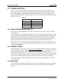
Table of Contents Introduction ......................................................................................................................1-1 How to Use This Manual ............................................................................................................... 1-2 Typographical Conventions .............................................................................................................................. 1-2 Illustrations ...................................................................................................................................................... 1-3 Christie Contact Information ........................................................................................................ 1-3 Safety Warnings and Guidelines .................................................................................................. 1-3 Stacking Limitations ......................................................................................................................................... 1-4 Using Christie PE50/PE67 Pedestals .................................................................................................................. 1-4 External Support .............................................................................................................................................. 1-4 Hardware ......................................................................................................................................................... 1-4 Lifting DiSplay Cubes ....................................................................................................................................... 1-5 Airflow Considerations ..................................................................................................................................... 1-5 Installation & Setup ..........................................................................................................2-1 Components ................................................................................................................................... 2-2 Tools Required ................................................................................................................................................. 2-3 Service and Support ......................................................................................................................................... 2-3 Installation ..................................................................................................................................... 2-3 Step 1 - Unpacking Cube Enclosures and Pedestals .......................................................................................... 2-3 Step 2 - Unpack and Stabalize Screens ............................................................................................................. 2-4 Step 3 - Unpack and Prepare Projectors for Installation ..................................................................................... 2-5 Step 4 - Assemble the Pedestals ....................................................................................................................... 2-6 Step 5 - Install Display Cube Enclosures ............................................................................................................ 2-8 Step 6 - Apply Permanent External Support .................................................................................................... 2-12 Step 7 - Install Display Screens ....................................................................................................................... 2-13 Step 8 - Install Projectors into Cube Enclosures ............................................................................................... 2-16 Step 9 - Connect Sources ............................................................................................................................... 2-16 Step 10 - Power Projectors ON ....................................................................................................................... 2-17 Step 11 - Mechanical Setup: Adjust Image Geometry and Focus ..................................................................... 2-17 Step 12 - Software Setup: Optomize Image Setup and Display ....................................................................... 2-23 Appendix .......................................................................................................................... A-1 LIT MAN INSTALL Cube 013-100526-01 Rev. 1 (04/07) i 1 Introduction This installation manual contains important information for the safe and successful installation of a Christie CC50-3301 (CC50) or CC67-3801 (CC67) display cube system, whether as a single unit system or as a multiple unit system. Additional important information relating to the CC50/CC67 display cube system can be found in the RPMX/RPMSP-D120U User’s Manual. The installer should be familiar with all such information prior to commencing installation. In this section: • How to Use This Manual • Christie Contact Information • Safety Warnings and Guidelines LIT MAN INSTAL Cube 013-100526-01 Rev. 1 (04/07) 1-1 Section 1: Introduction CAUTION Installation of a display wall should be undertaken only by qualified installers having the requisite training, knowlege, skill and experience to properly install the system. PLEASE READ THIS INSTALLATION MANUAL CAREFULLY AND IN ITS ENTIRETY PRIOR TO COMMENCING INSTALLATION. 1.1 HOW TO USE THIS MANUAL This installation manual is intended to provide qualified installers with specific step-by-step installation information, from unpacking to advanced image setup. However, circumstances and conditions may vary from one installation site to another, and the installer has sole and final responsibility for ensuring that the system is installed with due regard for all relevant safety considerations. Installation steps are described in sequence and each step should be completed before moving on to the next step. NOTE: In this manual, it is assumed that Christie PE50/PE67 pedestals are used to create the main platform for a 2x2 display wall. 1.1.1 TYPOGRAPHICAL CONVENTIONS The following conventions are used throughout this manual: • Keypad commands and PC keystrokes appear in bold small caps, such as POWER, INPUT, ENTER etc. • References to specific areas of the document appear italicized and underlined. When viewed online the text appears in blue indicating a direct link to that section. For example, “Section 6 Specifications”. • References to other documents appear italicized and bold, such as Christie User Manual. • References to specific figures or tables within the document appear bold. When viewed online these references are in blue indicating a direct link to figure or table. For example, Figure 2.1, Table 4.3. • References to software menus and available options appear bold, such as Main Menu, Preferences. • User input or messages that appear on screen, in status display units or other control modules appear in Courier font. For example. “No Signal Present”, Login: christiedigital. • Error codes, LED status appear in bold, e.g. LP, A1 etc. • Operational states of modules appear capitalized, such as “power ON, power OFF”. Signal words, such as Warning, Caution and Notes are used in this manual to point the reader to specific information or instructions that warn of safety related hazards which may be present and how to avoid them. Observe all warnings and instructions marked on all products and product components. DANGER A WARNING ALERTS THE USER TO IMPORTANT OPERATING AND MAINTENANCE (SERVICING) INSTRUCTIONS IN THE LITERATURE ACCOMPANYING THE UNIT THAT IF NOT FOLLOWED WILL LEAD TO SEVERE BODILY HARM, OR DEATH. 1-2 LIT MAN INSTAL Cube 013-100526-01 Rev. 1 (04/07) Section 1: Introduction DANGER THE LIGHTNING FLASH AND ARROWHEAD SYMBOL WITHIN THE EQUILATERAL TRIANGLE ALERTS THE USER TO UNINSULATED "DANGEROUS VOLTAGE" WITHIN THE PROJECTOR'S ENCLOSURE THAT MAY BE OF SUFFICIENT MAGNITUDE TO CONSTITUTE A RISK OF ELECTRIC SHOCK THAT WILL LEAD TO SEVERE BODILY HARM, OR DEATH. WARNING A WARNING ALERTS THE USER TO IMPORTANT OPERATING AND MAINTENANCE (SERVICING) INSTRUCTIONS IN THE LITERATURE ACCOMPANYING THE UNIT THAT IF NOT FOLLOWED CAN LEAD TO SEVERE BODILY HARM, OR DEATH. CAUTION A CAUTION ALERTS THE USER TO IMPORTANT OPERATING AND MAINTENANCE INFORMATION THAT IF NOT FOLLOWED CAN LEAD MINOR OR MODERATE INJURY. NOTICE: A notice alerts the user to important operating and maintenance information that if not followed can lead to equipment damage. NOTE: A note provides additional information worthy of emphasis and may include tips on how to perform a specific task. 1.1.2 ILLUSTRATIONS All drawings are provided to enhance the understanding of the accompanying text. These graphics are representations only; they are not necessarily drawn to scale and may not represent your specific model. 1.2 CHRISTIE CONTACT INFORMATION * For the most current listings, refer to www.christiedigital.com 1.3 SAFETY WARNINGS AND GUIDELINES The following safety guidelines apply to all Christie CC50/CC67 display cube products, unless otherwise indicated. WARNING PLEASE READ THE FOLLOWING WARNINGS BEFORE COMMENCING INSTALLATION TO ENSURE THE SAFETY OF THOSE WORKING AT THE INSTALLATION SITE. LIT MAN INSTAL Cube 013-100526-01 Rev. 1 (04/07) 1-3 Section 1: Introduction 1.3.1 STACKING LIMITATIONS There are specific stacking limitations for each display cube product. Do not stack display cubes higher than the specified stacking limits when using the approved PE50/PE67 pedestal. (See Table 1.1 below.) Stacking display cubes higher than what is recommended increases the possibility of the display wall becoming unstable and unsafe and also increases the chance that the pedestals may buckle from the extra weight. Table 1.1 Model Stacking Limit CC50-3301 3 high CC67-3801 3 high CC50-3301E 5 high CC67-3801E 5 high 1.3.2 USING CHRISTIE PE50/PE67 PEDESTALS It is strongly recommended that PE50-xx01/PE67-xx01pedestals be used with CC50/CC67 display cube enclosures. It is the responsibility of the installer to ensure that CC50/CC67 cube enclosures are mounted to/within a secure structure that can adequately support the weight of the stacked display cubes. If a display wall is built with any other platform, it is the responsibility of the installer to ensure that the platform is stable and can support the weight of the display cubes (to their stacking limits) and provide enough mounting locations so that each display cube is fastened to it using its four mounting points. Display cubes, however mounted or secured, should only be stacked on a level surface and are not to be stacked on a non-level or inclined surface. Ensure pedestals are level before stacking display cubes. See also External Support. 1.3.3 EXTERNAL SUPPORT Stacked display cubes can tip over and cause injury or damage unless properly secured. It is extremely important the display wall be supported during and after installation to a structurally sound surface such as a permanent wall or an "installer-approved" free-standing external support structure. Under all circumstances, display cubes must be stacked on a level surface. If display cubes are stacked on a non-level or inclined surface, there is an increased risk that stacked cubes (even when mounted in secured or free-standing external structures) could tip over and cause serious injury or damage. It is strongly recommended that PE50/PE67 pedestals be used to create the platform for a CC50 or CC67 display wall. 1.3.4 HARDWARE Specific hardware is provided for fastening one display cube to another display cube or to a pedestal. Unless otherwise indicated, use all the hardware provided when fastening the various display cube products. 1-4 LIT MAN INSTAL Cube 013-100526-01 Rev. 1 (04/07) Section 1: Introduction 1.3.5 LIFTING DISPLAY CUBES A crew of two or more can lift a display cube into position on the first row. DANGER LIFT EQUIPMENT MUST BE USED TO LIFT DISPLAY CUBES INTO POSITION ON HIGHER ROWS. 1.3.6 AIRFLOW CONSIDERATIONS It is important that the room temperature measured all around the display wall is no greater than the operating temperature stated in the product specifications. It is up to the installer to determine, based on their installation, how much "open" area is required around the display wall for adequate airflow. LIT MAN INSTAL Cube 013-100526-01 Rev. 1 (04/07) 1-5 Section 1: Introduction 1-6 LIT MAN INSTAL Cube 013-100526-01 Rev. 1 (04/07) 2 Installation & Setup This section provides information on assembling CC50/CC67 components as a stand-alone unit or as a multi-unit display wall. In this section: • 2.1 Components • 2.1.1 Tools Required • 2.1.2 Service and Support • 2.2 Installation • 2.2.1 Step 1 - Unpacking Cube Enclosures and Pedestals • 2.2.2 Step 2 - Unpack and Stabalize Screens • 2.2.3 Step 3 - Unpack and Prepare Projectors for Installation • 2.2.4 Step 4 - Assemble the Pedestals • 2.2.5 Step 5 - Install Display Cube Enclosures • 2.2.6 Step 6 - Apply Permanent External Support • 2.2.7 Step 7 - Install Display Screens • 2.2.8 Step 8 - Install Projectors into Cube Enclosures • 2.2.9 Step 9 - Connect Sources • 2.2.10 Step 10 - Power Projectors ON • 2.2.11 Step 11 - Mechanical Setup: Adjust Image Geometry and Focus • 2.2.12 Step 12 - Software Setup: Optomize Image Setup and Display LIT MAN INSTAL Cube 013-100526-01 Rev. 1 (04/07) 2-1 Section 2: Installation & Setup 2.1 COMPONENTS All major components required to assemble a complete display cube are carefully packaged and shipped separately to the installation site. This includes the display cube enclosure, projector and the display screen. Each component comes with enough hardware for installation. PE50/PE67 pedestals are also carefully packaged and shipped fully assembled with hardware. Check the contents of your shipment with the list below to ensure you have received all necessary components. For CC50-3301 Cube Enclosures: 8-M6 x 75mm hex screws 16 -M6 flat washers 8-M6 split washers 12-M6 hex nuts 4-M6 (M8 Head) x 737mm screen bolts 2-M6 x 60mm hex screws For CC67-3801 Cube Enclosures: 10-M6 x 75mm hex screws 20-M6 flat washers 10-M6 split washers 10-M6 hex nuts 4-M6 (M8 Head) x 852mm screen bolts 2-M6 x 60mm hex screws For PE50 and PE67 Pedestals: 4-M6 x 75mm hex screws 8-M6 flat washers 4-M6 split washers 4-M6 hex nuts For RPMX-D120U or RPMS-D120U Projectors: 2-2 4 positioning tubes (sized specifically for projector model) L-shaped configuration bracket (for lens-horizontal configuration) Power Cord LIT MAN INSTAL Cube 013-100526-01 Rev. 1 (04/07) Section 2: Installation & Setup In addition to the contents of the display cube enclosure, each display system is provided with a User’s Kit* which includes the following components: RPMX/RPMSP-D120U User’s Manual CC50/CC67 Installation Manual IR remote keypad with 2AA batteries Assorted ball drivers A pair of lint free cotton gloves (required for screen handling) *Additional User’s Kits can be purchased separately by referencing the Christie part number (102138101-01) when ordering. 2.1.1 TOOLS REQUIRED It is recommended the following tools be kept on hand during installation: • • • • Eye-leveling tools Adjustable wrench Torque wrench Phllips #2 screwdriver 2.1.2 SERVICE AND SUPPORT Fully trained service technicians are available to quickly diagnose and correct system related problems. If you encounter any problems during the setup and installation of your system, contact the authorized dealer from which the system was purchased. NOTE: The term ‘Dealer’ can also refer to ‘Christie Partner’. 2.2 INSTALLATION Steps required to assemble a display wall are listed in the order they should be completed. Always complete one step before moving on to the next. WARNING ONLY QUALIFIED, EXPERIENCED INSTALLERS SHOULD ATTEMPT INSTALLATION OF A CHRISTIE DISPLAY WALL. 2.2.1 STEP 1 - UNPACKING CUBE ENCLOSURES AND PEDESTALS Make sure you unpack components in the location you intend to install them. To prepare components for assembly, complete the following: 1. Remove and discard all packaging surrounding each component. 2. Remove the rear access panel from each display cube enclosure by loosening the screws around the perimeter of the panel (Figure 2-1). Use the moulded handles at the top of the panel to lift the panel slightly to clear the screws, and then pull to remove. Set the panel aside in a low traffic area where it will not be damaged. It will not be re-installed until the very end of installation. LIT MAN INSTAL Cube 013-100526-01 Rev. 1 (04/07) 2-3 Section 2: Installation & Setup FIGURE 2-1 REMOVING THE REAR ACCESS COVER 3. Remove the packaging material used to protect the optical mirror. Make sure not to bump or scratch the mirror while doing this. Also, do not touch the optical mirror with your bare hands. NOTE: Fingerprints left on the surface can impact the quality of a displayed image. 4. Located on the side panels (near the bottom of the cube) and top of the display cube are four openings used to route cables from one projector to the next in a display wall (See Figure 2-7). Install a cable cover (from the outside) over each opening to finish the look of the display cube and also to protect cables from rubbing up against the raw edge of the opening. 2.2.2 STEP 2 - UNPACK AND STABALIZE SCREENS It is strongly recommended that screens be stabilized to the environmental conditions of a site for at least 24 hours prior to installation*. By allowing screens to stabilize, you have a greater chance of maintaining the screen gap set between them in an installation. To prepare screens for installation, do the following: 1. Wearing the lint free cotton gloves provided in the User’s Kit, remove the screen from its packaging. 2. Allow screens to stand vertically for at least 24 hours, if not more at the installation site. In order to to prevent a screen from getting scratched or tipping over, it is recommend to lean then against a wall or flat surface. This should be done in an area which is away from the cube installation to prevent upset or accidental damage to the screens. Also, do not lay screens flat. Since screens are one of the last major components to install, keep them in a low traffic area during the build. * For maximum benefit, allow the screen to stabilize to ambient site conditions for up to 14 days prior to installation. 2-4 LIT MAN INSTAL Cube 013-100526-01 Rev. 1 (04/07) Section 2: Installation & Setup 2.2.3 STEP 3 - UNPACK AND PREPARE PROJECTORS FOR INSTALLATION The projector is shipped fully assembled in a lens-vertical configuration. To prepare it for installation, complete the following: 1. Remove all packaging surrounding the projector. NOTES: 1) It is recommended that complete packaging for at least one projector be kept on-hand in the unlikely event that a project needs to be returned to the factory for servicing or replacement. 2) Keep the 4 positioning tubes provided with each projector, as they will be needed to install the projector into the cube enclosure. The L-shaped bracket is not required during the installation process and can be discarded or kept in the event you want to use your projector in a lenshorizontal installation. 2. Check all cable connections between modules of the projector. If required, refer to Figure 2-2 below and reconnect or tighten loose cables. FIGURE 2-2 CONNECTING PROJECTOR CABLES 3. Remove the lock screw located on the mechanical lamp changer. This screw is used for shipping purposes only and must be removed before the projector is turned on. IMPORTANT NOTICE: Failure to remove the lock screw can result in projector damage. See Figure 2-3. FIGURE 2-3 REMOVE LOCK SCREW FROM MECHANICAL LAMP CHANGER LIT MAN INSTAL Cube 013-100526-01 Rev. 1 (04/07) 2-5 Section 2: Installation & Setup 2.2.4 STEP 4 - ASSEMBLE THE PEDESTALS It is strongly recommended that PE50/PE67 pedestals (Figure 2-4) are used in creating the platform for a CC50/CC67 display wall. These pedestals are designed specifically to support the CC50/CC67 cube enclosures to their maximum stacking limit. Before you begin assembly of the pedestal (Figure 2-5), ensure you have the correct pedestal model for your display cube. A CC50 display cube requires a PE50-xx01 pedestal and a CC67 requires a PE67xx01 pedestal. Make sure all pedestal models are the same, since there are various pedestal heights available. Tools/hardware required: eye-leveling tool ball driver 4-M6 x 75 mm hex screws, 8 flat washers, 4 split washers, 4-M6 hex nuts TIPS: Depending on the size of your wall, assemble the platform beginning with the center two pedestals working out to each end of the row. FIGURE 2-4 INDENTIFYING PEDESTAL COMPONENTS FIGURE 2-5 PEDESTAL MOUNTING LOCATIONS 2-6 LIT MAN INSTAL Cube 013-100526-01 Rev. 1 (04/07) Section 2: Installation & Setup When constructing a PE50/PE67 platform (multiple pedestals), complete the following: Refer to Figure 2-6 (panel #3) for correct screw location. 1. Slide two pedestals together aligning front and rear edges until flush. 2. Using a level, determine which side(s) of the pedestal require adjustment. Then as required, adjust the pedestal feet until the two pedestals are level on all sides and with each other. Make sure the pedestal feet remain fully engaged in the pedestal - look at the inside corners of the pedestal to confirm this. If you cannot see any threads at the top of the corner bracket where the foot is installed, then you have over-extended the pedestal foot and must correct this before moving on. 3. Loosely fasten the two pedestals together using 4 M6 x 75mm hex screws, 8 flat washers, 4 split washers, 4-M6 hex nuts and 4 split washers. Keeping the hardware a little loose at this point will allow you to tweak alignment between pedestals more pedestals are added to the platform. 4. Slide the next pedestal into position and using a level adjust the height in the same manner as #2 above until the pedestal becomes level with the pedestals already in the row. 5. Repeating #3 - #4 above, continue adding pedestals onto the row adjusting height as required. 6. Once you have confirmed your platform is level and that all rear edges between pedestals are flush, tighten the loose hardware to secure them in place. 7. Re-verify leveling of the entire platform structure. NOTICE: Ensure that the Feet are flat to the floor by applying downward bodyweight pressure on the pedestal. FIGURE 2-6 ASSEMBLING A PE50/PE67 PEDESTALS LIT MAN INSTAL Cube 013-100526-01 Rev. 1 (04/07) 2-7 Section 2: Installation & Setup 2.2.5 STEP 5 - INSTALL DISPLAY CUBE ENCLOSURES Refer to Figure 2-7 and Figure 2-8. Tools/hardware required: Eye-leveling tool Ball driver For CC50 - 8-M6 x 75mm hex screws, 16 flat washers, 8 split washers, 8-M6 hex nuts For CC67 - 10-M6 x 75 mm hex screws, 20 flat washers, 10 split washers, 10-M6 hex nuts For each CC50 screen, 4-M6 x 737 mm screen bolts For each CC67 screen, 4-M6 x 852 mm screen bolts For top row only, use two of the long screen bolts with 2-M6 x 50 mm screws for each screen TIPS: The long screen holding bolts should be inserted into the back of the cubes before the cubes are installed on the structure. These systems are usually installed close to a back wall and if you don't put the rods in before putting the cube on the structure it will be very difficult to install them afterward. Install cube enclosures starting from the center and working outwards. Alignment is the key to the successful installation of rows of display cubes. Always ensure edges of display cubes are flush before adding on another row. This will reduce issues with image geometry once the screens are installed and ensure the wall has a “seamless” appearance. It is more difficult and time consuming to try and fix an alignment problem near the bottom of a wall. WARNING ALWAYS EXTERNALLY SUPPORT THE DISPLAY WALL AS IT IS BEING CONSTRUCTED, REGARDLESS OF ITS HEIGHT, TO PREVENT IT FROM TIPPING AND CAUSING SERIOUS INJURIES TO THOSE AT THE INSTALLATION HEIGHT. FIGURE 2-7 IDENTIFYING CUBE ENCLOSURE COMPONENTS 2-8 LIT MAN INSTAL Cube 013-100526-01 Rev. 1 (04/07) Section 2: Installation & Setup FIGURE 2-8 CUBE ENCLOSURE MOUNTING LOCATIONS Add the FIRST ROW of display cube enclosures Refer to Figure 2-9. 1. There are 17 3-mm hex-cap screws on the outer edge of mirror frame used to secure the optical mirror for transport. Slightly loosen each of these screws (approximately 1/4 turn) to relax the optical mirror. NOTICE: This should be done before the screen is installed (Section 2.2.7) as some of these screws are difficult to access from the back of the cube enclosure. 2. The cube is also shipped with thumbscrews (some installed/remainder in separate kit) on the top and bottom face of the mirror frame. These are used for adjustment of mirror linearity. NOTICE: Temporarily remove the bottom-center thumbscrews (if installed) as this may damage the lens upon installation of the light engine. Replace once the light engine is installed. 3. Loosen the four black lock nuts at the corners of the mirror. 4. Install the first row of display cube enclosures onto pedestals, beginning with the centre and working outward, by completing the following: a. Approaching the pedestal from the back, use proper lifting methods to lift the cube enclosure over the pedestal and lower it in place. With the display cube enclosure resting on the pedestal, adjust its alignment so that the side and rear edges between the two components are flush and mounting holes are aligned. b. Using four M6 x 75mm screws with washers and hex nuts, secure the cube to the pedestal below. *Hand-tighten the hardware at this point to allow small adjustments while other display cubes are added to that row. NOTE: For a single, stand-alone unit tighten the hardware until components are fully secured, then proceed to Step 6 - Installing Screens. c. Add the second display cube onto the platform using the same method as described in a. and b. above. d. Secure adjacent display cubes together. *Hand-tighten hardware only at this point. • When securing one side of CC50, use four M6 x 75mm screws with washers and hex nuts • When securing one side of CC67, use six M6 x 75mm screws with washers and hex nuts e. Continue this procedure until all display cubes have been added to the first row. LIT MAN INSTAL Cube 013-100526-01 Rev. 1 (04/07) 2-9 Section 2: Installation & Setup f. Check alignment between all display cubes, and since the hardware is relatively loose make small adjustments as required. g. Tighten all hardware between display cubes and pedestals before adding on the next row of display cubes. Some adjustment of the pedestal feet may be required to achieve a level row. FIGURE 2-9 INSTALL FIRST ROW OF DISPLAY CUBE ENCLOSURES Adding ADDITIONAL ROWS of display cube enclosures Refer to Figure 2-10. 1. Make sure the wall is externally supported (Section 2.2.6) before adding on the second row of display cubes beginning with the centre and working outward. a. Using safe and approved lifting methods, install the next display cube over the lower cube approaching it from the back. Once it is resting on the frame of the lower cube, you can slide the display cube forward until it is in position. b. Align the top and bottom display cube until all edges are flush and mounting holes are aligned. c. Using four M6 x 75mm screws with washers and hex nuts and secure display cubes together. *Hand-tighten the hardware at this point to allow small adjustments while other display cubes are added to that row. d. Add the second display cube onto the row. e. Secure adjacent display cubes together. *Hand-tighten hardware only at this point. • When securing one side of CC50, use four M6 x 75mm screws with washers and hex nuts • When securing one side of CC67, use six M6 x 75mm screws with washers and hex nuts f. Continue this process until all display cubes have been added to the row. g. Check alignment between all display cubes, and since the hardware is relatively loose make small adjustments as required. 2-10 LIT MAN INSTAL Cube 013-100526-01 Rev. 1 (04/07) Section 2: Installation & Setup h. Tighten all hardware between top and bottom display cubes before adding on the next row of display cubes. i. Continue adding ADDITIONAL ROWS until all display cubes are installed. j. Install Christie Nameplate (component in User Kit) in the top-right corner of the far right pedestal as shown in Figure 2-11. FIGURE 2-10 ADDING ADDITIONAL ROWS OF DISPLAY CUBE ENCLOSURES FIGURE 2-11 INSTALL CHRISTIE NAMEPLATE LIT MAN INSTAL Cube 013-100526-01 Rev. 1 (04/07) 2-11 Section 2: Installation & Setup 2.2.6 STEP 6 - APPLY PERMANENT EXTERNAL SUPPORT A CC50/CC67 display wall requires some method of external support regardless of its overall height. The method and frequency of external support must be determined by a qualified installer. Reinforcing the structure will prevent the wall from tipping due to unforseen circumstances, such as earthquakes etc. WARNING 1) EXTERNAL SUPPORT FOR A DISPLAY WALL MUST BE DESIGNED AND IMPLEMENTED BY A QUALIFIED INSTALLER. 2) ALL DISPLAY WALLS MUST BE PERMANENTLY EXTERNALLY SUPPORTED. Consider the following when designing external support for a display wall: • Review local building codes for specific requirements • Size of the installation (how many display cubes are being stacked?) • Physical characteristics of the cube installation (including weight, center of gravity, mounting hole location) See Appendix A for technical information on all display wall components. • Are PE50/PE67 pedestals used to form the platform for the wall? This is strongly recommended. • Type of material being considered for external support • The strength / stability of the vertical or horizontal surface to which external support will be secured • Required frequency of external support Examples of External Support Figure 2-12 illustrates only two possible external support methods for a display wall. Consider your options, and ensure the method you choose best supports your specific installation. NOTE: Although the cubes in Figure 2-12 are shown with the screens installed, this is for illustrative purposes only. The screens are actually installed in the next section. FIGURE 2-12 EXAMPLES OF EXTERNAL SUPPORT 2-12 LIT MAN INSTAL Cube 013-100526-01 Rev. 1 (04/07) Section 2: Installation & Setup 2.2.7 STEP 7 - INSTALL DISPLAY SCREENS Tools/hardware required: For each CC50 screen, 4-M6 x 737 mm screen bolts For each CC67 screen, 4-M6 x 852 mm screen bolts For top row only, use two of the short screen bolts with 2-M6 x 50 mm screws for each screen Torque wrench TIPS: Extend the two screen support set screws before installing a screen. This will ensure the weight of the screen is transfered to the pedestal/display cube below. NOTICE: Failure to do this can result in screens bowing or damaging other screen elements. When used properly, these screws can be used to set an even screen gap. You MUST wear cotton gloves, provided in the User’s Kit, when handling screens to prevent getting fingerprints on the surface. Install screens starting in the center of the bottom row and work out towards the end. Then repeat on the next row, center screen first. To install screens, complete the following: 1. Add the 10 screen adjustment screws: 2 depth screws in each corner (Figure 2-13) and two height adjustment screws at the bottom. Install them so that they are flush with the inside surface of the Screen frame. FIGURE 2-13 INSTALL DEPTH ADJUSTMENTS SCREWS 2. Starting with the centre cube, and working in pairs, lift the screen into position at the front of the display cube. Make sure the screen is in the proper orientation with the two support screws at the bottom. These screws should be fully extended at this point. See Figure 2-14 and Figure 2-15. 3. With one person supporting the screen from the front, have another secure the screen in place using four long threaded rods inserted from the back (installed in Step 5 - Section 2.2.5) of the display cube. For CC50, use four M6 x 737 mm threaded rods and for CC67, use four M6 x 852mm threaded rods. *Hand-tighten the hardware only at this point, which will allow you some room to make small alignment adjustments to the screen as other screens are being installed. LIT MAN INSTAL Cube 013-100526-01 Rev. 1 (04/07) 2-13 Section 2: Installation & Setup 4. Working outward from the centre cube, repeat 1 - 3 above for the next screen. Ensure that there is a 0.5 mm gap between each screen. 5. Continue the process of adding screens, one at a time until all screens are added on the first row. Check along the way that screens are level and the gap is even between them (approximately 0.5mm). 6. Temporarily hand-tighten screen hardware until next row is installed. 7. When installing screens on additional rows, repeat steps 1-5 above (see Figure 2-16). Always complete installation of screens on one row before starting on the next row. Alignment and screen gap issues must be corrected before adding an additional row of screens. A misalignment is very difficult to correct once all screens are in place. Adjust the screens depth adjustment screws to ensure screen flatness. Once the second row of screens has been installed, adjust the depth screws on the first row of screens and lock when completed. Once the third row of screens has been installed, adjust the depth screws on the second row and lock when completed. Continue until all rows have been completed. 8. Tighten screen hardware to a maximum torque setting of 8.5ft.lb to secure. NOTE: You may also be required to adjust the pedestal feet in order to attain a level row. 9. For screens on the TOP ROW, use two long screen bolts to secure the bottom of the screen and two short M6-50 mm screws to secure the top. FIGURE 2-14 INSTALL SCREENS TO THE FIRST ROW 2-14 LIT MAN INSTAL Cube 013-100526-01 Rev. 1 (04/07) Section 2: Installation & Setup FIGURE 2-15 FULLY EXTEND SCREEN ADJUSTMENT SCREWS FOR SUPPORT FIGURE 2-16 INSTALLING SCREENS ON SECOND ROW OR HIGHER LIT MAN INSTAL Cube 013-100526-01 Rev. 1 (04/07) 2-15 Section 2: Installation & Setup 2.2.8 STEP 8 - INSTALL PROJECTORS INTO CUBE ENCLOSURES Tools required: The four positioning tubes shipped with the projector. These are used to nominally position the projector within the cube enclosure To properly install the projector into a cube enclosure, complete the following (Refer to Figure 2-17): NOTICE: Keep the lens cap on the projector during installation to prevent damaging the lens. 1. Remove the knurled thumb-nut from each post inside the cube enclosure. Do not remove the lower nut. 2. Slide a single positioning tube, supplied with the projector, over each post (and nut). Ensure the nut sits well below the top of the positioning tube. This may require some adjusting. 3. From the rear of the display cube, install the projector over the four posts. NOTE: The input panel and adjuster controls should face the back of the enclosure. 4. With the projector resting on the positioning tubes, replace the knurled thumbwheel removed earlier, and hand-tighten until the projector is secure. 5. Ensure the lamp-locking (shipping) screw has been removed. 6. Repeat Steps 1- 4 until all projectors for your installation are installed. FIGURE 2-17 INSTALL PROJECTOR INTO DISPLAY CUBE USING POSITIONING TUBES 2.2.9 STEP 9 - CONNECT SOURCES A variety of external sources can be connected to the input panel of the projector. Properly routing the cables from one projector to another in the display wall will keep them from becoming tangled or falling into the optical light path affecting the displayed image. Each display cube enclosure is designed with two openings on the side, two openings on the top and channels in the belly pan to allow for source and power cables to be easily routed . You can choose to route cables across a row of display cubes and up the wall or you can route cables from top to bottom, starting in one corner. Whichever method you choose, maintain consistency across the wall until all projectors are connected. NOTICE: It is recommend that power and signal cables be separated (where possible) and routed perpendicular to each other; for example, route power vertically and signals horizontally. 2-16 LIT MAN INSTAL Cube 013-100526-01 Rev. 1 (04/07) Section 2: Installation & Setup 2.2.10 STEP 10 - POWER PROJECTORS ON Each projector is supplied with a North American rated line cord. Make sure you use an appropriately rated line cord for your area before connecting the projectors to AC. Refer to the RPMX/RPMSPD120U User’s Manual for projector power requirements and other Specifications. 1. Plug one end of the line cord to the AC receptacle on the projector, which is located on the electronics module. Then plug the 3-pronged end into a grounded AC outlet. Do not use a line cord or AC supply not in the specified voltage and power range. 2. Turn the main power switch ON. 3. Press the power button on the remote control for two seconds to turn the projector ON. Wait to see “On” displayed in the LED status display. Do not enter a keypad command until this occurs otherwise the command will be ignored. 4. Press one of the input keys on the remote to select and display the image from that source. NOTES: 1) The projector enforces a 60 second wait period from the time the projector is powered down and back up again. 2) Refer to the RPMX/RPSMP-D120U User’s Manual for additional information on the remote keypad and the various features of the projector. 2.2.11 STEP 11 - MECHANICAL SETUP: ADJUST IMAGE GEOMETRY AND FOCUS The primary objective in this step is to adjust a displayed image and adjust its geometry so that it fits squarely on the screen filling in all edges and corners. This step applies to a single or multiple display wall. With a display wall, the goal is to display one image across all screens and have it appear “seamless” to the audience. Any geometric irregularities will impact the overall appearance of your wall. Optimizing the quality of the image such as brightness, color matching etc. is done in Step 12 after the wall is mechanically adjusted. Tools Required: 8mm ball driver provided in the User’s Kit to adjust the 6-axis adjustment mechanism on the projector TIPS (general): When you have a large display wall to adjust, take your time. This is an important step in how your overall display wall will appear. Adjust one projector at a time until the entire wall is adjusted. Do not over-adjust the screws on the 6-axis adjuster. If the screws get a little harder to turn during adjustment, STOP. This indicates the end of adjustment range for that screw. 1) It is recommended you make small 1/4 - 1/2 turn adjustments with the 6-axis adjuster to achieve your desired image. This will make it easier to return the adjuster back to an original position, in the event you lose track of your adjustments and want to start over. 2) If the adjuster’s vertical adjustment becomes difficult, try reducing the tilt settings to see if you can gain any vertical movement. LIT MAN INSTAL Cube 013-100526-01 Rev. 1 (04/07) 2-17 Section 2: Installation & Setup To adjust a display for image geometry, complete the following: 1. Ensure that the series of 3-mm hex-cap screws on the edge of the optical mirror frame have been loosened (approximately 1/4 turn) to relax the optical mirror. NOTE: See section 2.2.5 Step 5 Install Display Cube Enclosures. 2. Prepare the screen for mechanical adjustment, by completing the following steps: a. Display an internal Test Pattern on each screen. Press the ‘Test’ button until the following test pattern (Edge Blend) is displayed: It is strongly recommended you choose a test pattern that displays a solid outside border with bold geometric shapes such as a circle and square. Displaying this type of pattern will make it easier to identify any distortion present in the image. b. Adjust the focus of the display. c. Repeat the steps above for each display. 3. Adjust image geometry using the projector’s 6-axis adjustment mechanism. The light engine is mounted to this mechanism, which provides a range of motion in the x, y and z axes. By moving the light engine within this range you can fine-tune the geometry of a displayed image. The 6-axis mounting adjustment mechanism is designed to also provide coarse adjustments. Coarse adjustments (movements of the light engine of about 1/2”) are typically not required since the display cube enclosure and projector are optimally designed for placement. However, if coarse adjustments are required they can be achieved by following the instructions provided separately in the Mounting section of the Appendix. TIPS (6-axis adjuster): 2-18 Do not over-adjust the screws on the 6-axis adjustment mechanism. If you begin to feel a slight resistance when adjusting, STOP. This indicates the end of adjustment range for that screw. It is recommended you make small 1/4 - 1/2 turn adjustments with the 6-axis adjuster to achieve your desired image. This will allow you to control adjustments and make it easier to return the adjuster to a previous position relatively quickly. LIT MAN INSTAL Cube 013-100526-01 Rev. 1 (04/07) Section 2: Installation & Setup If the adjuster’s vertical adjustment becomes difficult, try reducing the tilt settings (make flat) to see if you can gain any vertical movement. Keep height adjustments within 1mm of each other to reduce substantial differences in tilt. Refer to the illustration below as you adjust the 6-axis adjuster in the following manner: a. b. c. d. e. f. Center the image on screen, by adjusting vertical and/or horizontal position. Zoom in the image (make smaller) until it fits within the borders of the screen Adjust keystone and tilt. Zoom in the image (make larger) to completely fill the screen. Repeat any of the adjustments until the image appears correct. Repeat a. - e. above for each display. 4. Adjust the optical mirror. Perform this adjustment only if you are unable to achieve a geometric image on screen using the steps above. In most cases, the adjustment range available with the 6axis adjuster is enough for image adjustment. There are two types of screws available for adjustment, see Figure 2-18. The small thumbscrews, located around the perimeter of the mirrror, can be used to correct an image that is 1-2 pixels out from any corner or edge. The four brass screws, located on separate brackets, can be used to adjust an image 1-4 pixels from any corner. The adjustment of these screws will impact how an image is LIT MAN INSTAL Cube 013-100526-01 Rev. 1 (04/07) 2-19 Section 2: Installation & Setup displayed within a corresponding zone of the screen (Figure 2-19). In some cases, more than one screw will require adjustment. Read through the following tips and review the examples provided. There is no steadfast way in which the mirror is adjusted. In general, fix the corners of the image first, then the edges if required. Just keep in mind, this is a fine adjustment of the image only. NOTE: Adjust the optical mirror only when image geometry cannot be corrected using the 6-axis adjuster. Adjustment of the optical mirror is meant for fine adjustments only. TIPS for optical mirror adjustment: Recommended first step in optical mirror adjustment: Adjust brass screws (not thumbscrews on the mirror) to fix the corners of an image. See Figure 2-20. When adjusting a thumbscrew on the mirror, always loosen the corresponding screw on the opposite side. NOTICE: If this is not done before making adjustments, the mirror can crack or break due to the stress placed on it. Adjust thumbscrews on the front side of the mirror to enlarge the image and adjust thumbscrews on the rear side of the mirror to reduce the image. Only finger-tighten thumbscrews when making mirror adjustments. NOTICE: Do not use any tools to tighten thumbscrewes as over-tightening may cause the mirror to crack. Multiple screws may require adjustment to achieve the correct image. Always start by fixing corners first then edges. Figure 2-18 and Figure 2-19 show the location of adjustment screws on the mirror and the corresponding zone on the screen they affect. For example, to enlarge the image in zone A of the screen, adjust the front thumbscrews located in that area. FIGURE 2-18 LOCATION OF OPTICAL MIRROR ADJUSTMENT SCREWS 2-20 LIT MAN INSTAL Cube 013-100526-01 Rev. 1 (04/07) Section 2: Installation & Setup FIGURE 2-19 CORRESPONDING SCREEN ZONES AFFECTED BY OPTICAL MIRROR ADJUSTMENT Adjusting brass screws: When adjusting any corner of an image, whether to enlarge or make smaller, adjust one of the four brass screws first. These screws are located on a separate brackets near each corner of the mirror. See Figure 2-20. To adjust these screws, loosen the lower black nut first, then turn the larger nut just above it in either a clockwise direction (pulls the mirror back to enlarge the image) or counter-clockwise direction (brings the mirror forward reducing size of the image) until the desired image is achieved. Remember to make small adjustments. This adjustment is only meant to correct an image that is 1-4 pixels out. FIGURE 2-20 ADJUST BRASS SCREWS TO FIX CORNERS OF AN IMAGE Examples: The following examples are provided to illustrate what areas of the optical mirror you should adjust in order to achieve the desired image. In general, try correcting the corner(s) of the image first, then the edges. In some cases, reducing adjustment of one screw in one direction will give the mirror a little more play in the other. CAUTION BEFORE ADJUSTING A SCREW ON THE MIRROR, ALWAYS LOOSEN THE CORRESPONDING SCREW ON THE OPPOSITE SIDE. THIS WILL REDUCE STRESS PLACED ON THE MIRROR AND THE POTENTIAL FOR IT TO CRACK OR BREAK. LIT MAN INSTAL Cube 013-100526-01 Rev. 1 (04/07) 2-21 Section 2: Installation & Setup 2-22 LIT MAN INSTAL Cube 013-100526-01 Rev. 1 (04/07) Section 2: Installation & Setup 2.2.12 STEP 12 - SOFTWARE SETUP: OPTOMIZE IMAGE SETUP AND DISPLAY Use the instructions in the following step to optimize the settings of the projector to display the brightest and sharpest image possible. Adjust each display separately, then “tweak” your settings between all displays until you achieve the ultimate display. This is an outline only, refer to the RPMX/ RPMSP-D120U User’s Manual for detailed instructions on how to adjust the various settings. 1. Display an external signal. 2. From the Lamp menu, select a lamp operation mode: Lamp 1 or Lamp 2. For the purpose of adjusting a display wall, perform all software setups using this lamp mode. 3. Assign each projector a unique identification number. This ID number will allow you to “speak” specifically with a projector in a wall instead of broadcasting commands to all. 4. Select the correct image orientation for your display. From the Configuration menu, select Image Orientation and choose Inverted Front to display the image correctly on a rear screen display. 5. Adjust the way in which the menus appear on screen, by adjusting the options available in Menu Preferences (found under the Configuration menu). 6. From the Communications menu, enable the Broadcast key. This will allow you to relay commands from one projector to others in the serial network. 7. Select Auto Setup which allows the projector to optimize its settings for the current incoming signal. 8. From Image Settings, verify the Processing Mode to ensure it is correct for the selected source. 9. From Size and Position, adjust Pixel Phase and Pixel Tracking to eliminate any noise from the displayed image. 10. From Size and Position, adjust H-Position and V-Position to re-center the image on screen, if needed. LIT MAN INSTAL Cube 013-100526-01 Rev. 1 (04/07) 2-23 Section 2: Installation & Setup 11. From Size and Position, adjust Size until the image is at the desired width and height. You may have to adjust H-Position and V-Position again to re-center the image after adjusting these settings. Continue this step until the image is centered on screen. 12. Adjust Color Wheel Delay. 13. Perform Color Temperature setup. 14. Adjust blacklevels and input levels. 15. Adjust lamp power to match lamp brightness of adjacent displays, if needed. 2-24 LIT MAN INSTAL Cube 013-100526-01 Rev. 1 (04/07) A LIT MAN INSTAL Cube 013-100526-01 Rev. 1 (04/07) Appendix A-1 APPENDIX A-2 LIT MAN INSTAL Cube 013-100526-01 Rev. 1 (04/07) APPENDIX LIT MAN INSTAL Cube 013-100526-01 Rev. 1 (04/07) A-3 APPENDIX A-4 LIT MAN INSTAL Cube 013-100526-01 Rev. 1 (04/07)