1
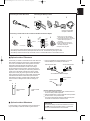
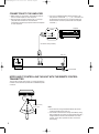
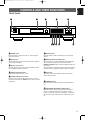
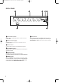
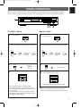
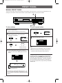
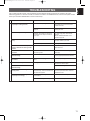
TX396L(Eng)99.11.25 99.11.26 4:52 PM Page 1
BG
TX-396L
Natural Sound AM/FM Stereo Tuner
Syntonisateur AM/FM stéréo de la série “Natural Sound”
OWNER’S MANUAL
MODE D’EMPLOI
BEDIENUNGSANLEITUNG
BRUKSANVISNING
MANUALE DI ISTRUZIONI
MANUAL DE INSTRUCCIONES
GEBRUIKSAANWIJZING
TX396L(Eng)99.11.25 99.11.26 4:52 PM Page 2
SUPPLIED ACCESSORIES
ACCESSOIRES FOURNIS
MITGELIEFERTE ZUBEHÖRTEILE
MEDFÖLJANDE TILLBEHÖR
ACCESSORI IN DOTAZIONE
ACCESORIOS INCLUIDOS
BIJGELEVERDE ACCESSOIRES
●
●
●
●
●
●
●
●
●
●
●
●
●
●
●
●
●
●
●
●
●
After unpacking, check that the following parts are contained.
Après le déballage, vérifier que les pièces suivantes sont incluses.
Nach dem Auspacken überprüfen, ob die folgenden Teile vorhanden sind.
Kontrollera efter det apparaten packats upp att följande delar finns med.
Verificare che tutte le parti seguenti siano contenute nell’imballaggio dell’apparecchio.
Desembalar el aparato y verificar que los siguientes accesorios están en la caja.
Controleer na het uitpakken of de volgende onderdelen voorhanden zijn.
Indoor FM Antenna
Antenne FM intérieure
UKW-Innenantenne
FM inomhusantenn
Antenna FM per interni
Antena FM interior
FM Binnenantenne
●
Audio connection cord
Câble de connexion audio
Audio-Anschlußkabel
Audio anslutningssladdar
Cavo di collegamento audio
Cable de conexión de audio
Audio aansluitkabel
●
●
●
●
●
●
●
●
●
●
●
●
●
AM Loop Antenna
Cadre-antenne AM
MW-Rahmenantenne
AM ramantenn
Antenna AM ad anello
Antena de cuadro de AM
AM Lusantenne
75-ohm/300-ohm antenna adapter (U.K. model only)
Adaptateur d’antenne 75 ohms/300 ohms
(Modèle Royaume-Uni seulement)
75-Ohm/300-Ohm Antennenstecker
(nur Großbritannien-Modell)
75 ohm/300 ohm antennadapter
(gäller endast modellen för Storbritannien)
Adattatore per antenna da 75 e 300 ohm
(Soltanto il modello per la Gran Bretagna)
Adaptador de antena de 75-ohmios/300-ohmios
(Sólo el modelo para el Reino Unido)
75 ohm/300 ohm antenneadapter
(Alleen modellen voor Verenigd Koninkrijk)
TX396L(Eng)99.11.25 99.11.26 4:52 PM Page 3
•
•
•
•
•
FEATURES
CONTENTS
40 Station Random Access Preset Tuning
Automatic Preset Tuning
Multi-Status Station Memory
Direct PLL Synthesizer Tuning
Preset Station Shifting Capability (Preset Editing)
Caution............................................................................1
Connections ....................................................................2
Controls and Their Functions..........................................5
Tuning Operations ..........................................................7
Preset Tuning..................................................................8
Troubleshooting ............................................................11
Specifications................................................................12
English
Thank you for selecting this YAMAHA stereo tuner
CAUTION: READ THIS BEFORE OPERATING YOUR UNIT.
1. This unit is a sophisticated stereo tuner. To assure proper
operation and the best possible performance, please read
this manual carefully.
2. Choose the installation location for the unit carefully.
Avoid placing it in direct sunlight or close to a source of
heat. Also avoid locations subject to vibration and
excessive dust, heat, cold or moisture. Keep it away from
such sources of hum as transformers or motors.
3. Do not open the cabinet, because this may result in
damage to the unit or electrical shock. If a foreign object
should get into the unit, contact your local dealer.
4. When not planning to use this unit for long periods of time
(ie., vacation, etc.), disconnect the AC power plug from the
wall outlet.
5. To prevent lightning damage, disconnect the AC power
plug and disconnect the antenna cable when there is an
electrical storm.
6. When disconnecting the power plug from the wall outlet,
always pull directly on the plug; never pull the cord itself.
7. Do not use force when operating switches and other
controls.
8. When moving the unit, be sure to first disconnect the
power plug and disconnect all wires connected from the
unit to other equipment.
9. Do not attempt to clean this unit with chemical solvents,
because this may damage the finish. Use a clean, dry
cloth.
10. Be sure to read the “TROUBLESHOOTING” section of this
manual for advice on common operating errors before
concluding that the unit is faulty.
11. Keep this manual in a safe place for future reference.
IMPORTANT
Please record the serial number of this unit in the space
below.
Serial No.:
The serial number is located on the rear of the unit.
Retain this Owner’s Manual in a safe place for future
reference.
WARNING
TO REDUCE THE RISK OF FIRE OR ELECTRIC SHOCK,
DO NOT EXPOSE THIS APPLIANCE TO RAIN OR
MOISTURE.
The apparatus is not disconnected from the AC power
source as long as it is connected to the wall outlet, even if
the apparatus itself is turned off.
For U.K. customers
If the socket outlets in the home are not suitable for the plug
supplied with this appliance, it should be cut off and an
appropriate 3 pin plug fitted. For details, refer to the
instructions described below.
Note: The plug severed from the mains lead must be
destroyed, as a plug with bared flexible cord is hazardous if
engaged in a live socket outlet.
Special Instructions for U.K. Model
IMPORTANT
THE WIRES IN THE MAINS LEAD ARE COLOURED IN
ACCORDANCE WITH THE FOLLOWING CODE:
Blue: NEUTRAL
Brown: LIVE
The colours of the wires in the mains lead of this apparatus
may not correspond with the coloured markings identifying
the terminals in your plug. Proceed as follows: the wire
which is coloured BLUE must be connected to the terminal
which is marked with the letter N or coloured BLACK. The
wire which is coloured BROWN must be connected to the
terminal which is marked with the letter L or coloured RED.
Making sure that neither core is connected to the earth
terminal of the three pin plug.
1
TX396L(Eng)99.11.25 99.11.26 4:52 PM Page 4
CONNECTIONS
Never plug in this unit and other components until all connections are completed.
ANTENNA CONNECTIONS
●
●
Each antenna should be connected to the designated terminals correctly, referring to the following figure.
Both AM and FM indoor antennas are included with this unit. In general, these antennas will probably provide sufficient signal
strength. Nevertheless, a properly installed outdoor antenna will give clearer reception than an indoor one. If you experience
poor reception quality, an outdoor antenna may result in improvement.
Outdoor FM antenna
Outdoor AM antenna
Indoor FM
antenna
(included)
FM ANT
GND
AM loop
antenna
(included)
AM ANT
75Ω UNBAL.
75-ohm
antenna
adapter
300-ohm
feeder
75-ohm
coaxial cable
2
75-ohm/300-ohm
antenna adapter
Ground
TX396L(Eng)99.11.25 99.11.26 4:52 PM Page 5
English
Connecting the indoor FM antenna
Connecting the AM loop antenna
1
2
3
2
1
3
Orient so that the best
reception is obtained.
Connecting a coaxial cable to the included 75-ohm/300-ohm antenna adapter
1
2
3
4
Lead wire
Cover
5
Clamp
with
pliers
Clamp
with
pliers
Insert
the wire
into the
slot
Unit:mm(inch)
1 Open the cover of the included
75-ohm/300-ohm antenna adapter.
2 Cut the external sleeve of the 75-ohm
coaxial cable and prepare it for
connection.
3 Cut the lead wire and remove it.
4 Insert the cable wire into the slot,
and clamp it with pliers.
5 Snap the cover into place.
* If you connect an outdoor FM antenna to this unit, do not connect the indoor FM antenna to this unit.
* The AM loop antenna should be placed apart from the main unit. The antenna may be hung on a wall.
* The AM loop antenna should be kept connected, even if an outdoor AM antenna is connected to this unit.
■ Optional outdoor FM antenna
Consult with your dealer or authorized service center about the
best method of selecting and erecting an outdoor FM antenna.
The choice of the feeder cable is also important. Flat ribbonshaped twin-lead cable performs well electrically, and is
cheaper and somewhat easier to handle when routing it
through windows and around rooms. Coaxial cable is more
expensive, does a much better job of minimizing interference,
is less prone to the effects of weather and close-by metal
objects, and is nearly as good a signal conductor as feeder
cable, particularly for foam-type coaxial cables. Coaxial cable
is somewhat more difficult to install at the point where the
cable enters the building. If coaxial cable is selected, make
sure the antenna is designed to be used with that type of
cable.
300-ohm feeder
cable
75-ohm coaxial
cable
■ Optional outdoor AM antenna
In steel buildings or at a great distance from the transmitter, it
may be necessary to install an outside long wire antenna.
* Use a 75-ohm/300-ohm antenna adapter or a 75-ohm
antenna adapter (not included) for connections.
300-ohm feeder cable
75-ohm coaxial cable
75-ohm/300-ohm antenna adapter
75-ohm coaxial
cable
75-ohm antenna
adapter
Notes for FM antenna installation
To minimize automobile ignition noise, locate the antenna
as far from heavy traffic as possible.
● Keep the feeder cable or coaxial cable as short as possible.
Do not bundle or roll up excess cable.
● The antenna should be at least two meters (6.6 feet) from
reinforced concrete walls or metal structures.
●
GND terminal
For maximum safety and minimum interference, connect
the GND terminal to a good earth ground. A good earth
ground is a metal stake driven into moist earth.
3
TX396L(Eng)99.11.25 99.11.26 4:52 PM Page 6
CONNECTIONS TO THE AMPLIFIER
●
●
Before making any connections, switch OFF the power to
this unit and the amplifier or other component.
Be sure that the connections from the left (“L”) and right
(“R”) LINE OUT terminals are connected to the
corresponding (left and right) input terminals of the amplifier
or other component.
●
If you have a YAMAHA amplifier whose terminals on the
rear panel are numbered as 1, 2, 3, etc., connections can
be made easily by making sure to connect the LINE OUT
terminals of this unit to the input terminals of the amplifier
numbered 2.
Amplifier
TUNER
L
R
Connection cord (included)
This unit
FM ANT
GND
LINE OUT
AM ANT
75Ω UNBAL.
R
L
2
To AC outlet
NOTES ABOUT CONTROLLING THIS UNIT WITH THE REMOTE CONTROL
TRANSMITTER
This unit has a remote control sensor. It receives signals from
a remote control transmitter provided with a YAMAHA amplifier
or receiver.
Remote control
sensor
Within approximately
6 m (19.7 feet)
Notes
There should be no large obstacles between the remote
control transmitter and the main unit.
● If the remote control sensor is directly illuminated by strong
lighting (especially an inverter type of fluorescent lamp etc.),
it might cause the remote control transmitter not to work
correctly. In this case, reposition the main unit to avoid
direct lighting.
●
4
TX396L(Eng)99.11.25 99.11.26 4:52 PM Page 7
English
CONTROLS AND THEIR FUNCTIONS
FRONT PANEL
1
2
NATURAL SOUND
3
4
5
AM/FM STEREO TUNER
1
PRESET STATIONS
2
3
4
POWER
TUNING
DOWN
5
A/B/C/D/E
6
MEMORY
7
EDIT
MAN'L/AUTO FM
UP
8
TUNING MODE
AUTO/MAN'MONO
67 8 9
0
1 POWER switch
Press this switch to switch the power on. Press it again to
switch the power off.
6A/B/C/D/E button
Press this button to select a desired group (A–E) of preset
stations.
2 Display panel
Shows station frequencies and various information. (Refer to
the next page for details.)
7 MEMORY (MAN’L/AUTO FM) button
When this button is pressed, the MEMO indicator flashes for
about 5 seconds. During this period, press the desired
PRESET STATIONS button to enter the displayed station into
the memory.
When this button is pressed and held for about 3 seconds, the
automatic preset tuning begins. (Refer to page 9 for details.)
3 Remote control sensor
Receives signals from a remote control transmitter provided
with a YAMAHA amplifier or receiver.
4 PRESET STATIONS buttons
Select a preset station number (1 to 8).
5 TUNING DOWN and UP buttons
Used for tuning. Press the “UP” button to tune in to higher
frequencies, and press the “DOWN” button to tune in to lower
frequencies.
8 EDIT button
This button is used to exchange the places of two preset
stations with each other.
9 FM/MW/LW button
Press this button to switch the reception band to FM, MW or
LW.
0TUNING MODE (AUTO/MAN’L MONO) button
Press this button to switch the tuning mode to automatic or
manual. To select the automatic tuning mode, press this
button so that “AUTO” lights up on the display. To select the
manual tuning mode, press this button so that “AUTO” goes
off.
5
TX396L(Eng)99.11.25 99.11.26 4:52 PM Page 8
DISPLAY PANEL
1
2
3
4 5
AUTO
kHz
MHz
ST
EDIT
MEMO
6
1 Preset station indicator
Display the group (A/B/C/D/E) and the number (1 to 8) of a
preset station.
2 Station frequency display
Displays the band and frequency or information from the
received station.
3 AUTO indicator
Lights up when this unit is in the automatic tuning mode.
4 ST (STEREO) indicator
Lights up when an FM stereo broadcast with sufficient signal
strength is received.
5 Signal-level meter
Indicates the signal level of the received station.
If multipath interference is detected, the indication decreases.
6 MEMO indicator
When the MEMORY button is pressed, this indicator flashes
for about 5 seconds. During this period, the displayed station
can be programmed to the memory by using the A/B/C/D/E
button and one of the PRESET STATIONS buttons.
6
7
7 EDIT indicator
Flashes by the first press of the EDIT button when you will
exchange preset stations, and lights up for a moment by the
second press of the EDIT button to show that the exchange
has succeeded.
TX396L(Eng)99.11.25 99.11.26 4:52 PM Page 9
Normally, if station signals are strong and there is no interference, quick automatic-search tuning (AUTOMATIC TUNING) is
possible. However, if signals of the station you want to select are weak, you must tune to it manually (MANUAL TUNING).
English
TUNING OPERATIONS
1
23
AUTOMATIC TUNING
MANUAL TUNING
1
Turn the power on.
2
Select the reception band confirming it on the display.
POWER
FM/MW/LW
1
Turn the power on.
2
Select the reception band confirming it on the display.
POWER
FM/MW/LW
,
3
4
or
,
3
TUNING MODE
AUTO
AUTO/MAN'MONO
or
TUNING MODE
AUTO/MAN'MONO
Turn “AUTO” off.
4
4
Tune to a desired station manually.
TUNING
DOWN
UP
TUNING
DOWN
UP
* To continue tuning search, press and hold the button.
To tune to a higher frequency, press the UP button.
To tune to a lower frequency, press the DOWN button.
* If the station where tuning search stops is not the desired
one, press again.
* If the tuning search does not stop at the desired station
(because the signals of the station are weak), change to
the MANUAL TUNING method.
Notes
If you tune to an FM station manually, it is received in
monaural mode automatically to increase the signal quality.
•
7
TX396L(Eng)99.11.25 99.11.26 4:52 PM Page 10
PRESET TUNING
MANUAL PRESET TUNING
This unit can store station frequencies selected by tuning operation. With this function, you can recall any desired station by only
selecting the preset station number where it is stored. Up to 40 stations (8 stations x 5 groups) can be stored.
4, 2
2, 1 3
To recall a preset station
To store stations
1
2
1
Tune to a desired station.
(Refer to the previous page for tuning procedure.)
Select the group of preset stations.
A/B/C/D/E
Select a desired group (A – E) of preset stations
confirming it on the display.
2
A/B/C/D/E
Select the preset station number.
1
3
5
PRESET STATIONS
2
3
6
7
4
8
MEMORY
MEMO
MAN'L/AUTO FM
Flashes on and off
for about 5 seconds.
4
Select a preset station number where you want to
program the station before “MEMO” goes off from the
display.
1
5
PRESET STATIONS
2
3
6
7
Memory back-up
The memory back-up circuit prevents the programmed data
from being lost even if the POWER switch is set off or the
power plug is disconnected from the AC outlet or the power is
cut due to temporary power failure. If, however, the power is
cut for more than one week, the memory may be erased. If
so, it can be re-programmed by simply following the PRESET
TUNING steps.
4
8
AUTO
ST
MHz
Shows the displayed station has been
programmed to A1.
* In the same way, program other stations to A2, A3 ... A8.
* You can program more stations to preset station numbers
on other groups in the same way by selecting other groups
in step 2.
8
Notes
A new setting can be programmed in place of the former
one.
• For presets, the setting of the reception mode (stereo or
monaural) is stored along with the station frequency.
•
TX396L(Eng)99.11.25 99.11.26 4:52 PM Page 11
You can also make use of an automatic preset tuning function for FM stations only. By this function, this unit performs automatic
tuning and stores FM stations with strong signals sequentially. Up to 40 stations are stored automatically in the same way as in the
manual preset tuning method on page 8.
English
AUTOMATIC PRESET TUNING
2 1
To store stations
When the automatic preset tuning is finished
1
The display shows the frequency of the last preset station.
Check the contents and the number of preset stations by
following the procedure of the section “To recall a preset
station” on page 8.
To recall a preset station
FM/MW/LW
Simply follow the procedure of the section “To recall a preset
station” on page 8.
Notes
● If no station is received by the automatic preset tuning
search, the search finishes after “NOTHING” flashes for
about 3 seconds on the display.
●
You can replace a preset station by another FM, MW or LW
station manually by simply following the procedure of the
section “To store stations” on page 8.
●
The automatic preset tuning search will be performed
through all FM frequencies until stations are stored up to E8.
If the number of received stations is not enough to be stored
up to E8, the search is finished automatically after searching
all frequencies.
●
With this function, only FM stations with sufficient signal strength
are stored automatically. If the station you want to program is
weak in signal strength, tune in to it with the MANUAL TUNING
method (in monaural) and program it by following the procedure
of the section “To store stations” on page 8.
2
MEMORY
MAN'L/AUTO FM
Press and hold for
about 3 seconds.
AUTO
ST
MHz
MEMO
Flashes.
The automatic preset tuning begins from the frequency
currently displayed. Received stations are programmed to
A1, A2 ... A8 sequentially.
* If more than 8 stations are received, they are also
programmed to the preset station numbers on other groups
(B, C, D and E) in that order.
9
TX396L(Eng)99.11.25 99.11.26 4:52 PM Page 12
EXCHANGING PRESET STATIONS
You can exchange the places of two preset stations with each other as shown below.
2, 4
Example)
If you want to shift the preset station on E1 to A5, and vice
versa.
1
Recall the preset station on E1 (by following the method
of “To recall a preset station” on page 8).
4
EDIT
2
EDIT
ST
MHz
EDIT
PRESET
Flashes.
3
Next, recall the preset station on A5 by following the
same method with step 1.
EDIT
ST
MHz
PRESET
EDIT
Lights up for a moment.
Flashes.
Shows the exchange of stations is completed.
10
TX396L(Eng)99.11.25 99.11.26 4:52 PM Page 13
If the unit fails to operate normally, check the following points to determine whether the fault can be corrected by the simple
measures suggested. If it cannot be corrected, or if the fault is not listed in the SYMPTOM column, disconnect the power cord and
contact your authorized YAMAHA dealer or service center for help.
SYMPTOM
AM (MW/LW)
FM
Crackling sounds from time to time
(especially in weak signal areas).
CAUSE
REMEDY
Ignition noise from passing vehicles.
The FM antenna should be put up as high
as possible, away from the road, and a
coaxial cable used.
Noise from thermostats or other electrical
equipment.
Attach a noise suppressor to the equipment
causing the noise.
FM stereo reception is noisy.
Because of the characteristics of FM stereo
broadcasts, this is limited to cases where
the transmitter is far away or the antenna
input is poor.
Check the antenna connections.
Try using a high quality directional FM
antenna.
Set the TUNING MODE button to the
manual tuning mode.
The ST indicator flickers and reception is
noisy.
Insufficient antenna input.
Use an antenna appropriate for the
reception condition in your area.
Not tuned correctly.
Tune again.
There is distortion and clear reception
cannot be obtained even with a good FM
antenna.
There is multipath interference.
Adjust antenna placement to eliminate multipath interference.
No stereo effect even with a stereo
broadcast.
The TUNING MODE button is set to the
manual tuning mode.
Set the button so that “AUTO” lights up on
the display.
A desired station cannot be tuned in with
Automatic tuning.
The station is too weak.
Use the manual tuning mode.
Use a high quality directional FM antenna.
Previously preset stations can no longer
be tuned in.
The tuner has been unplugged for a long
period.
Repeat the presetting procedure.
Insufficient sensitivity.
Weak signal or loose antenna connections.
Tighten the AM loop antenna connections
and rotate it for best reception.
A desired station cannot be tuned in with
Automatic tuning.
English
TROUBLESHOOTING
Use the manual tuning mode.
There are continuous crackling and
hissing noises.
These noises result from lightning,
fluorescent lamps, motors, thermostats and
other electrical equipment.
Use an outdoor antenna and a ground wire.
This will help somewhat but it is difficult to
eliminate all noises.
There are buzzing and whining noises
(especially in the evening).
Another station is interfering with the
received station.
This is impossible to remedy.
A television set is being used nearby.
Relocate this unit away from the TV.
11
TX396L(Eng)99.11.25 99.11.26 4:52 PM Page 14
SPECIFICATIONS
FM SECTION
AM (MW) SECTION
Tuning Range ...................................................87.5 to 108 MHz
Tuning Range
.................................................................531 to 1,611 kHz
Usable Sensitivity ........................................................200 µV/m
Harmonic Distortion; 1 kHz .................................................0.3%
Usable Sensitivity (DIN)
75 ohms Mono (S/N 26 dB) ........................................0.9 µV
75 ohms Stereo (S/N 46 dB)........................................24 µV
AM (LW) SECTION
Selectivity (two signals, 40 kHz Dev., ±300 kHz)
...................................................................................70 dB
Signal-to-Noise Ratio
(DIN-Weighted)
Mono (40 kHz Dev.)...................................................75 dB
Stereo (40 kHz Dev.) ................................................70 dB
Harmonic Distortion (1 kHz)
(40 kHz Dev.)
Mono/Stereo ......................................................0.1%/0.2%
Stereo Separation (1 kHz)
(40 kHz Dev.).............................................................50 dB
Tuning Range .....................................................153 to 288 kHz
Usable Sensitivity ........................................................400 µV/m
Signal-to-Noise Ratio.........................................................50 dB
Harmonic Distortion; 1 kHz .................................................0.3%
AUDIO SECTION
Output Level
FM (100 % mod. 1 kHz)
(40 kHz Dev.)
................................................................................500 mV
AM (30% mod. 1 kHz)
................................................................................200 mV
GENERAL
Frequency Response
20 Hz to 15 kHz....................................................0±1.5 dB
Power Supply
........................................................................230V, 50 Hz
Power Consumption ..............................................................7W
Dimensions (W x H x D) ...............................435 x 86 x 278 mm
(17-1/8” x 3-3/8” x 10-15/16”)
Weight ..........................................................3.2 kg (7 lbs. 1 oz.)
Accessories .............................................Audio connection cord
AM loop antenna
Indoor FM antenna
* Specifications subject to change without notice.
12
TX396L(Dut)99.11.25 99.11.26 4:03 PM Page 118
YAMAHA
YAMAHA
YAMAHA
YAMAHA
YAMAHA
YAMAHA
YAMAHA
ELECTRONICS CORPORATION, USA 6660 ORANGETHORPE AVE., BUENA PARK, CALIF. 90620, U.S.A.
CANADA MUSIC LTD. 135 MILNER AVE., SCARBOROUGH, ONTARIO M1S 3R1, CANADA
ELECTRONIK EUROPA G.m.b.H. SIEMENSSTR. 22-34, 25462 RELLINGEN BEI HAMBURG, F.R. OF GERMANY
ELECTRONIQUE FRANCE S.A. RUE AMBROISE CROIZAT BP70 CROISSY-BEAUBOURG 77312 MARNE-LA-VALLEE CEDEX02, FRANCE
ELECTRONICS (UK) LTD. YAMAHA HOUSE, 200 RICKMANSWORTH ROAD WATFORD, HERTS WD1 7JS, ENGLAND
SCANDINAVIA A.B. J A WETTERGRENS GATA 1, BOX 30053, 400 43 VÄSTRA FRÖLUNDA, SWEDEN
MUSIC AUSTRALIA PTY, LTD. 17-33 MARKET ST., SOUTH MELBOURNE, 3205 VIC., AUSTRALIA
V490720