1
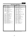
THIS MANUAL CONTAINS THE OPERATING
INSTRUCTIONS AND SAFETY INFORMATION FOR YOUR SCAG MOWER. READING
THIS MANUAL CAN PROVIDE YOU WITH
ASSISTANCE IN MAINTENANCE AND ADJUSTMENT PROCEDURES TO KEEP YOUR
MOWER PERFORMING TO MAXIMUM EFFICIENCY. THE SPECIFIC MODELS THAT THIS
BOOK COVERS ARE CONTAINED ON THE
INSIDE COVER. BEFORE OPERATING YOUR
MACHINE, PLEASE READ ALL THE INFORMATION ENCLOSED.
OPERATOR’S MANUAL
MODEL STT-31BSG
PART NUMBER
TABLE OF CONTENTS
SUBJECT
PAGE
Section 1 - General Information
1.1 Introduction .............................................................................................................................1
1.2 Directional Reference .............................................................................................................1
1.3 Servicing the Engine and Drive Train Components ................................................................1
Section 2 - Safety Information
Symbols ............................................................................................................................... 2-3
2.1 Introduction .............................................................................................................................4
2.2 Signal Words ...........................................................................................................................4
2.3 Before Operation Considerations ...........................................................................................4
2.4 Operation Considerations ........................................................................................................5
2.5 Maintenance Considerations ...................................................................................................6
2.6 Safety and Instructional Decals ..............................................................................................7
Section 3 - Specifications ....................................................................................................... 8-9
Section 4 - Operating Instructions
4.1 Controls and Instrument Identification .................................................................................. 10
4.2 Safety Interlock System ........................................................................................................ 11
4.3 Initial Run-In Procedures ...................................................................................................... 12
4.4 Starting the Engine ................................................................................................................ 12
4.5 Ground Travel and Steering .................................................................................................. 12
4.6 Engaging the Deck Drive ..................................................................................................... 13
4.7 Hillside Operation ................................................................................................................. 14
4-8 Parking the Mower ............................................................................................................... 14
4.9 After Operation .................................................................................................................... 14
4.10 Removing Clogged Material ................................................................................................. 15
4.11 Moving Mower with Engine Stopped ................................................................................... 15
4.12 Recommendations for Mowing ............................................................................................. 15
4.13 Adjusting Cutting Height ....................................................................................................... 16
Section 5 - Troubleshooting Cutting Conditions............................................................. . 17-19
I
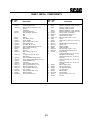
TABLE OF CONTENTS (CONT'D)
SUBJECT
PAGE
Section 6 - Adjustments
6.1 Parking Brake Adjustment .................................................................................................... 20
6.2 Travel Adjustments ............................................................................................................... 20
6.3 Throttle Control and Choke Adjustments .............................................................................. 22
6.4 Belt Adjustment .................................................................................................................... 22
6.5 Belt Alignment ...................................................................................................................... 22
6.6 Cutter Deck Adjustments ..................................................................................................... 23
Section 7 - Maintenance
7.1 Maintenance Chart ............................................................................................................... 25
7.2 Lubrication Fitting Points ...................................................................................................... 26
7.3 Hydraulic System .................................................................................................................. 28
7.4 Engine Oil ............................................................................................................................. 29
7.5 Engine Fuel System .............................................................................................................. 30
7.6 Engine Air Cleaner ................................................................................................................ 30
7.7 Battery .................................................................................................................................. 30
7.8 Drive Belts ............................................................................................................................ 32
7.9 Cutter Blades ........................................................................................................................ 32
7.10 Tires ...................................................................................................................................... 33
7.11 Cutter Deck Gearbox ........................................................................................................... 34
7.12 Cooling System ..................................................................................................................... 34
7.13 Body, Deck, Hopper and Upholstery .................................................................................... 35
Section 8 - Illustrated Parts List
SMST 61"Adv., 72" Adv. Cutter Decks ................................................................................... 36-37
Cutter Deck Controls ................................................................................................................ 38-39
Sheet Metal Components .......................................................................................................... 40-41
Deck Drive Components .......................................................................................................... 42-43
Radiator, Coolers & Engine Brackets.................................................................................44-45
Brake & Steering Components..... .....................................................................................46-47
Fuel & Hydraulic System ......................................................................................................... 48-49
Electrical System ...................................................................................................................... 50-51
Hydraulic Pump Assembly - BDP-21L .................................................................................... 52-53
Wire Harness, STT-31BSG ............................................................................................................ 54
Replacement Decals ................................................................................................................. 55-56
II
Section 1
GENERAL INFORMATION
For pictorial clarity, some illustrations and figures in this
manual may show shields, guards or plates open or
removed. Under no circumstances should your mower
be operated without these devices in place.
1.1 INTRODUCTION
Your mower was built to the highest standards in the
industry. However, the prolonged life and maximum
efficiency of your mower depends on you following the
operating, maintenance and adjustment instructions in this
manual.
All information is based upon product information
available at the time of approval for printing. Scag
Power Equipment reserves the right to make
changes at any time without notice and without
incurring any obligation.
If additional information or service is needed, contact
your Scag Power Equipment Dealer.
1.2 DIRECTION REFERENCE
We encourage you to contact your dealer for repairs. All
Scag dealers are informed of the latest methods to
service this equipment and provide prompt and efficient
service in the field or at their service shop. They carry a
full line of Scag service parts.
The “Right” and “Left”, “Front” and “Rear” of the
machine are referenced from the operator’s right and left
when seated in the normal operating position and facing
the forward travel direction.
USE OF OTHER THAN ORIGINAL SCAG
REPLACEMENT PARTS WILL VOID THE
WARRANTY.
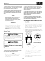
1.3 SERVICING THE ENGINE AND DRIVE
TRAIN COMPONENTS
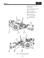
When ordering parts, always give the model and serial
number of your tractor. The serial number plate is
located where shown in Figure 1-1.
The detail servicing and repair of the engine, hydraulic
pumps and gearboxes are not covered in this manual;
only routine maintenance and general service instructions
are provided. For service of these components during
the limited warranty period, it is important to contact your
Scag dealer or find a local authorized servicing agent of
the component manufacturer. Any unauthorized work
done on these components during the warranty period
may void your warranty.
R
is
io
M n
P a of
at yv M
en il e
ts le, ta
Is W lcr
su is af
ed co t o
n f
an sin M
ay
d
P 53 vil
en 0 le
din 50 , I
nc
g
.
M
S OD
E E
R L
I
D AL
iv
M
4,4
A
N
U
O FA
F C
T T
4,8 8
7
4,9 8 ,0 HE UR
5
4,9 2 ,9 06 F E
0 0
O D
67 ,7 3
L U
,5 33
L N
43
O D
4,9 W E
P
A
4,9 9 IN R
1
T
5 9 ,3 G O
E
N 5 ,11 8,9 82 PA NE
T ,82 8,6 48
T O
S 6 1
E R
P ,41 7
N
E 6
5,8 T M
N
5,8 3 S: OR
D
2
IN
E
65 ,7
G
,0 08
18
SERIAL NUMBER
PLATE LOCATION
390S0137A
Figure 1-1 Tractor Serial Number Plate Location
1
Section 2
SAFETY INFORMATION
2.1 INTRODUCTION
Your mower is only as safe as the operator.
Carelessness or operator error may result in serious
bodily injury or death. Hazard control and accident
prevention are dependent upon the awareness, concern,
prudence, and proper training of the personnel involved in
the operation, transport, maintenance and storage of the
equipment. Make sure every operator is properly trained
and thoroughly familiar with all of the controls before
operating the mower.
The signal word “DANGER” denotes that an extremely
hazardous situation exists on or near the machine that
could result in high probability of death or irrepairable
injury if proper precautions are not taken.
WARNING:
The signal word “WARNING” denotes that a hazard
exists on or near the machine that can result in injury or
death if proper precautions are not taken.
READ THIS OPERATOR’S MANUAL BEFORE
ATTEMPTING TO START YOUR MOWER.
CAUTION:
A replacement manual is available from your authorized
Scag Service Dealer or by contacting Scag Power
Equipment, Service Department at P.O. Box 152,
Mayville, WI 53050. Please indicate the complete model
and serial number of your Scag product when requesting
replacement manuals.
The signal word “CAUTION” is a reminder of safety
practices on or near the machine that could result in
personal injury if proper precautions are not taken.
Your safety and the safety of others depends significantly
upon your knowledge and understanding of all correct
operating practices and procedures of this machine.
2.2 SIGNAL WORDS
2.3 BEFORE OPERATION
CONSIDERATIONS
1. NEVER allow children to operate this riding mower.
Do not allow adults to operate this machine without
proper instructions.
This symbol means “Attention! Become Alert! Your
Safety is Involved!" The symbol is used with the
following signal words to attract your attention to safety
messages found on the decals on the machine and
throughout this manual. The message that follows the
symbol contains important information about safety. To
avoid injury and possible death, carefully read the
message! Be sure to fully understand the causes of
possible injury or death.
2. DO NOT mow when children and/or others are
present.
3. Clear the area to be mowed of objects that could be
picked up and thrown by the cutter blades.
4. DO NOT carry passengers.
Signal Word:
5. DO NOT operate the machine under the influence
of alcohol or drugs.
It is a distinctive word found on the safety decals on the
machine and throughout this manual that alerts the
viewer to the existence and relative degree of the
hazard.
4
6. If the operator(s) or mechanic(s) cannot read English
it is the owner's responsibility to explain this material
to them.
Section 3
SPECIFICATIONS
SCAG "SABRE TOOTH TIGER" ZERO-TURN RIDER
MODEL: STT-31BSG
ENGINE
General Type:
Brand:
Model:
Horsepower:
Type:
Displacement:
Cylinders:
Governor:
Air Intake Group:
Exhaust Group:
Fuel Pump Group:
Oil Pump Group:
Valve Group:
Electrical/Charging System:
Heavy duty industrial commercial
Briggs Daihatsu Vanguard Liquid Cooled 31 HP
DM950G
31HP @ 3600 RPM
Water cooled 4 cycle, overhead valve, 3 cylinder, gas engine
952 cc
3 inline sleeves
High-speed flyweight governor, runs faster than engine crankshaft, provides precision speed
governing and a steady low idle, 3600 rpm (±100 rpm), idle set at 1500 rpm.
Canister type air filter system.
Single exhaust canister muffler.
Electric fuel pump with mechanical choke and fuel shutdown solenoid.
Positive displacement Geroter™ oil pump with remote oil filter, capacity 3.2 U.S. quarts
(3.0 ltrs) with oil filter.
Overhead.
12 volt battery with alternator, solid state ignition with key start, 40 amp regulated charging
system using a microprocessor and one ignition coil for each cylinder, solenoid shift type
starter.
ENGINE DECK
Fuel Tank:
Drive Wheels/Tires:
Parking Brake:
Frame:
10 gallon (38.0 liters) seamless polyethylene tank with fuel gauge gas cap.
24 x 12-12 four ply pneumatic tubeless, radius edge, offset rims to improve operator's view.
Lever operated interlocked parking brake prevents operation with parking brake engaged.
Compact tractor frame with structural steel tubing construction.
DRIVE SYSTEM
Type:
Hydro drive with two variable displacement pumps and two cast iron motors for independent control
of each drive wheel.
Hydro Pumps:
Two Hydro-Gear Model BDP 21L pumps with dump valves for movement without running engine.
Drive Wheel Motors:
Two 23 cubic inch cast iron high torque wheel motors.
Transmission Belt Idler:
Self adjusting, self tightening, sealed bearings.
Hydro Fluid Cooling Group:
6 qt. capacity Nylon fluid reservoir. Uses SAE 20W50 fluid and 10 micron filter.
Steering/Travel Control:
Twin lever fingertip steering control with gas shock dampeners for smooth, responsive control to
each wheel.
Axles:
1-1/4" heavy duty, tapered, motor shafts.
Wire Harness:
14 gauge wire.
Safety Group:
Seat actuated engine kill, neutral interlock, mower engagement (BBC) switch, parking brake.
Instrument Panel:
Voltmeter, water temperature gauge, oil pressure gauge, key switch, throttle, fuses, manual choke, BBC
switch (hourmeter located at rear of machine).
Forward Ground Speed Range: 0 to 10.5 mph.
Reverse Ground Speed Range: 0 to 5.0 mph.
Note: The machine will travel at 10.5 mph for transport purposes. For best cutting performance the
forward travel speed should be adjusted depending upon the cutting conditions.
8
Section 3
SPECIFICATIONS (con't)
SCAG "SABRE TOOTH TIGER" ZERO-TURN RIDER
MODEL: STT-31BSG
CUTTER DECK
Type:
Construction:
True Cutting Width:
Cutting Height Adjustment:
Cutter Blades:
Cutter Deck Drive:
Blade Engagement:
Discharge Opening:
Caster Wheels:
Spindles:
Spindle Pulleys:
Anti-scalp Rollers:
SMST-72A ("Advantage") & SMST-61A ("Advantage"): Floating, adjustable anti-scalping, hybrid
design combines out-front and belly-mount designs. "Advantage" - special extended front edge
allows Bahia or other tough grasses to enter the deck standing upright.
10 gauge steel top reinforced with 7 gauge support plate, deck skirt is 7 gauge steel.
72" deck = 71.5 inches (181.6 cm); 61" deck = 61.0" (155.0 cm).
Foot operated pedal adjustment from operator's seat, 1" to 6" in 1/2" increments.
72" = three (3) 24" blades; 61" = three (3) 21" blades.
Drive shaft to 90 degee gear box.
Electric blade engagement clutch with control panel knob.
Extra wide 11.5" discharge opening with spring loaded discharge chute.
13 x 5 x 6 caster wheels with tapered roller bearing pivots.
Heavy duty 1-1/8" top dimension spindle shaft, cast housing, taper roller bearing, low maintenance
with top access grease fitting and grease overfill relief poppet.
Cast iron with easily removed taper hubs.
Two front, two rear 4-1/2" adjustable, two rear 12" fixed.
ADDITIONAL SPECIFICATIONS
Seat:
Thick padded seat cushions with special springs. Padded arm rests, lever adjustment forward and
back.
APPROXIMATE DIMENSIONS
Length:
Tracking Width:
Width:
Width (with discharge chute up)
Height:
Turning Radius:
Weight:
72"
92.0"
56.0"
83.5"
73.0"
47.0"
Zero radius turn
1550 lbs.
61"
88.0"
56.0"
72.0"
61.5"
47.0"
Zero radius turn
1550 lbs.
PRODUCTIVITY
The following chart will aid you in determining how many acres your Scag mower will cut per day.
The chart is an estimate based on 8 hours per day cutting time at 4 MPH with an allowance for overlap and turns.
Cutting Width:
36"
48"
52"
61"
72"
Acres Per Day:
9.5
12.5
13.5
16
19
Date of issue: November, 2000
Specifications Subject to Change Without Notice.
9
Section 4
OPERATING INSTRUCTIONS
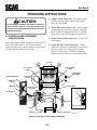
1. Ignition Switch (Figure 4-1). The ignition switch
is used to start the engine and has three positions;
OFF, ON, and START.
CAUTION:
Do not attempt to operate this mower unless you
have read this manual. Learn the location and
purpose of all controls and instruments before you
operate this mower.
2. Mower Deck Switch (Figure 4-1). Used to engage
and disengage the mower drive system. Pulling up
on the switch will engage the deck drive. Pushing
down on the switch will disengage the deck drive.
4.1 CONTROLS AND INSTRUMENT
IDENTIFICATION
3. Engine Choke Control (Figure 4-1). Used to start
a cold engine.
Before operating the mower, familiarize yourself with all
mower and engine controls. Knowing the location,
function and operation of these controls is important for
safe and efficient operation of the mower.
4. Engine Throttle Control (Figure 4-1). Used to
control the engine speed. Pushing the lever forward
increases engine speed. Pulling the lever back
decreases engine speed. Full back position is the
IDLE position. Full forward is the cutting position.
DECK LIFT
RIGHT STEERING
CONTROL
LEFT STEERING
CONTROL
CUTTING HEIGHT
ADJUSTMENT
WATER TEMPERATURE
PARKING BRAKE
CONTROL
MOWER DECK
SWITCH
DECK RELEASE
ENGINE THROTTLE
CONTROL
TEMPERATURE GAUGE
IGNITION SWITCH
MOWER DECK SWITCH
MOWER DECK
CHOKE
F
IGNITION SWITCH
ON
FUEL GAUGE
START
4 81 34 8
ENGINE
CHOKE
CONTROL
PULL OUT TO ENGAGE
PUSH IN TO DISENGAGE
AMMETER
481669
OFF
AMMETER
KAWASAKI MACHINE ONLY
FUSES
DUMP VALVE
DUMP VALVE
Figure 4-1 Controls and Hour Meter Instruments
10
390S0142A-1
Section 4
5. Voltmeter (Figure 4-1). Indicates the condition of
the charging system. When the engine is running, in
normal operating conditions, the needle should be in
the 12 to 14 volt range.
DUMP VALVE
CONTROL
6. Oil Pressure (Figure 4-1). Indicates engine oil
pressure. Reference the engine operator's manual
for further information.
7. Hourmeter (Figure 4-1). Indicates the number of
hours the engine has been operted. It operates
whenever the engine is running. It can be used to
keep track of maintenance intervals and the amount
of time required to perform various tasks.
Figure 4-2 Dump Valve Control
390S141-1
7. Fuse Holders (Figure 4-1). There are two 20-amp
fuses and one 40-amp fuse that protect the mower’s
electrical system. To replace fuses, pull fuse out of
the socket and install a new fuse.
15. Cutting Height Adjustment (Figure 4-1). Used to
set the cutter deck at the desired cutting height.
16. Deck Release Lever (Figure 4-1). Used to lock the
cutter deck in the transport position. Push the foot
pedal forward and lift up on the release lever to
release the cutter deck for normal mowing.
8. Left Steering Control (Figure 4-1). Used to
control the mower's left wheel when traveling
forward or reverse.
10. Right Steering Control (Figure 4-1). Used to
control the mower's right wheel when traveling
forward or reverse.
17. Temperature Gauge (Figure 4-1). Indicates the
operating temperature of the engine. Used on
mowers with the Kawasaki liquid cooled engine
only.
11. Parking Brake Control (Figure 4-1). Used to
engage and disengage the parking brakes. Pull the
lever back to engage the parking brakes. Push the
lever forward to disengage the parking brakes.
4.2 SAFETY INTERLOCK SYSTEM
The mower is equipped with a safety interlock system
that prevents the engine from starting unless the deck
drive is disengaged, the parking brake is engaged, the
steering control levers are in the neutral position and the
operator is in the seat. The interlock system shuts off
the engine if the operator leaves the seat with the steering
control levers not in the neutral position and/or the cutter
blades engaged and the parking brake not engaged.
12. Fuel Tank Gauge (Figure 4-1). Indicates the
amount of fuel in the fuel tank.
13. Dump Valve Control Levers (Figure 4-2).
Located on the hydraulic pumps, used to “freewheel” the mower. Rotating the levers clockwise
until they stop allows the unit to move under
hydraulic power. The levers must be in this position
during operation of the mower. Rotating the levers
counter-clockwise allows the mower to be moved by
hand (free-wheeling).
WARNING:
Never operate the mower with the interlock
system disconnected or malfunctioning. Do not
disengage or bypass any switch; injury to
yourself and others or property damage could
result.
14. Deck Lift Foot Lever (Figure 4-1). Used to raise
and lower the cutter deck.
11
Section 4
4.3 INITIAL RUN-IN PROCEDURES (First
Day of Use or Approximately 10 Hours)
7. Turn the ignition key to the START position and
release the key as soon as the engine starts. Do not
hold the key in the START position for more than 15
seconds at a time. Allow at least 60 seconds
between each cranking attempt to prevent
overheating of the starter motor. Prolonged cranking
can damage the starter motor and shorten battery
life.
1. Check all belts for proper alignment and wear at 2, 4
and 8 hours.
2. Change the engine oil and oil filter after the first 5
hours of operation. (See Section 7.4.)
8. Allow engine to warm before operating the mower.
3. Check hydraulic oil level in reservoir. (See Section
7.3.)
4.5 GROUND TRAVEL AND STEERING
4. Check for loose hardware. Tighten as needed.
-IMPORTANT5. Check interlock system for proper operation. (See
Section 4.2.)
If you are not familiar with the operation of a
machine with lever steering and/or hydrostatic
transmissions, the steering and ground speed
operations should be learned and practiced in
an open area, away from buildings, fences, or
obstructions. Practice until you are comfortable
with the handling of the machine before
attempting to mow. Learn the operation on flat
ground before operating on slopes.
6. Check tire pressure. Adjust pressure if necessary.
(See Section 7.10.)
4.4 STARTING THE ENGINE
CAUTION:
-IMPORTANT-
DO NOT USE STARTING FLUIDS. Use of starting
fluids in the air intake system may be potentially
explosive or cause a “runaway” engine condition
that could result in engine damage and/or personal
injury.
Start practicing with a slow engine speed and
slow forward travel.
Learn to feather the steering controls to obtain a
smooth operating action.
1. Be sure the fuel shutoff valve, located behind the
operator's seat, is completely open. (See section 7.5.)
Practice operating the mower until you are
comfortable with the controls before proceeding
to mow.
2. Sit in the operator’s seat and place the steering
control levers in the neutral position.
Forward Travel
3. Engage the parking brake.
To travel forward with the mower, disengage the parking
brake and slowly push the steering control levers
forward an equal distance. The further the steering
control levers are pushed forward the greater the forward
speed will be. To increase the speed, push the steering
control levers further forward and to decrease the speed,
pull the steering control levers back.
4. Place the PTO switch in the disengaged position.
5. If the engine is cold, choke the engine as needed.
6. Move the engine throttle control to about half
engine speed.
To stop the forward travel, pull the steering control
levers back to the neutral position.
12
Section 4
To steer the mower left while traveling forward, pull the
left steering lever back. The further the lever is pulled
back, the quicker the mower will turn left.
To steer left while traveling in reverse, allow the left
steering control lever to move forward. The further the
control is allowed to move forward, the quicker the
mower will turn left.
To steer the mower right while traveling forward, pull
the right steering control lever back. The further the
lever is pulled back, the quicker the mower will turn
right.
To steer right while traveling in reverse, allow the right
steering control lever to move forward. The further the
control is allowed to move forward, the quicker the
mower will turn right.
-NOTETo stop the reverse travel, allow the steering control
levers to return to the neutral position. If the mower is
to be parked, engage the parking brake.
Smooth operation of the steering levers will
produce smooth mower operation. While
learning the operation of the steering controls,
keep the travel speed low.
4.6 ENGAGING THE DECK DRIVE (CUTTER
BLADES)
-IMPORTANT1. Set the throttle at about 3/4 speed. Do not attempt to
engage the deck drive at high speed as this shortens
the electric clutch life — use only moderate engine
speed when engaging the deck drive.
Do not travel forward over a curb. The mower
will hang up on the curb. Raise the deck and
travel backwards over the curb at a 45 degree
angle. (see section 4.13 for cutter deck raising
instructions)
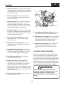
2. Engage the deck drive by pulling out on the yellow
switch, located on the instrument panel, (Figure 4-3)
to the engage position.
Reverse Travel
CAUTION:
Disengage power to the mower before backing
up. Do not mow in reverse unless absolutely
necessary and then only after observation of the
entire area behind the mower.
PULL UP TO ENGAGE
CAUTION:
PUSH DOWN TO DISENGAGE
Before backing up, observe behind the mower for
persons and obstructions. Clear the area before
backing up. Possible injury or property damage
could occur.
STT99CES
Figure 4-3 Cutter Engage Switch
-NOTEA squealing noise may be heard when engaging
or disengaging the deck drive. It is caused by
the electric clutch plates meshing as the mower
comes up to speed.
To travel in reverse, pull both handles back. Keep the
travel speed low while traveling in reverse.
-NOTEThe mower will not travel straight in reverse.
Slight adjustments must be made using the
steering controls.
3. To disengage the deck drive, push the switch in to
the disengage position.
13
Section 4
4.9 AFTER OPERATION
4. Always operate the engine at full throttle to properly
maintain cutting speed. If the engine starts to lug
down, reduce the forward speed and allow the
engine to operate at maximum RPM.
1. Wash the entire mower after each use. Do not use
high pressure spray or direct the spray onto electrical
components.
4.7 HILLSIDE OPERATION
-IMPORTANT-
WARNING:
Do not wash a hot or running engine. Cold
water will damage the engine. Use compressed
air to clean the engine if it is hot.
DO NOT operate on steep slopes. To check a slope,
attempt to back up it (with the cutter deck down). If
the machine can back up the slope without the
wheels slipping, reduce speed and use extreme
caution. ALWAYS FOLLOW OSHA APPROVED
OPERATION.
2. Keep the entire mower clean to inhibit serious heat
damage to the engine or hydraulic oil circuit.
3. Check the drive belts for proper alignment and any
signs of wear. Correct and adjust if necessary.
1. The mower has been designed for good traction and
stability under normal mowing conditions.
However, caution must be used when traveling on
slopes, especially when the grass is wet. Wet grass
reduces traction and steering control.
To avoid injury from burns, allow the mower to
cool before removing the fuel tank cap and
refueling.
2. To prevent tipping or loss of control, do not start or
stop suddenly, avoid unnecessary turns and travel at
reduced speed.
4. After the mower has cooled down, fill the fuel tank
with fresh, clean fuel at the end of every day of
operation.
3. Keep tires properly inflated.
5. Check the tire pressure. Adjust pressure if
necessary.
4.8 PARKING THE MOWER
1. Place the steering control levers in the neutral
position.
2. Disengage the cutter blades
3. Slow the engine to idle speed.
4. Engage the parking brake.
5. Turn the ignition key to the OFF position and
remove the key.
14
Section 4
4.10 REMOVING CLOGGED MATERIAL
5. When mowing wet or tall grass, mow the grass
twice. Raise the mower to the highest setting for the
first pass and then make a second pass to the desired
height.
ROTATING BLADES
6. Use a slow travel speed for trimming purposes.
NEVER PUT YOUR HANDS INTO THE DISCHARGE
CHUTE FOR ANY REASON! Shut off the engine
and remove the key and only then use a stick or
similar object to remove material if clogging has
occurred.
7. Operate the engine at full throttle for best cutting.
Mowing with a lower RPM causes the mower to tear
the grass. The engine is designed to be operated at
full speed.
1. If the discharge chute becomes clogged, shut off the
engine and remove the ignition key. Using a stick or
similar item, dislodge the clogged material. Then
resume normal mowing.
8. Use the alternate stripe pattern for best lawn
appearance. Vary the direction of the stripe each
time the grass is mowed to avoid wear patterns in
the grass.
4.11 MOVING MOWER WITH ENGINE
STOPPED
To “free-wheel” or move the mower around without the
engine running, place the dump valve levers in the
FREE-WHEEL position (Figure 4-2). Disengage the
parking brake and move the mower by hand. The dump
valve levers must be returned to the DRIVE position to
drive the mower.
4.12 RECOMMENDATIONS FOR MOWING
1. Do not mow with dull blades. A dull blade will tear
grass, resulting in poor lawn appearance and require
extra power.
2. The discharge chute must not be removed and must
be kept in the lowest position to deflect grass
clippings and thrown objects downward. Direct the
side discharge away from sidewalks or streets to
minimize cleanup of clippings. When mowing close
to obstacles, direct the discharge away from the
obstacles to reduce the chance of property damage
by thrown objects.
3. Cut grass when it is dry and not too tall. Do not cut
grass too short (cut off 1/3 or less of existing grass
for best appearance). Mow frequently.
4. Keep mower and discharge chute clean.
15
Section 6
6.6 CUTTER DECK ADJUSTMENTS
3. Tighten the serrated hex nut to secure the cutter
deck in the proper position.
Cutter deck level, pitch and height are set at the factory.
However, if these adjustments should ever need to be
made, the following procedures will aid in obtaining the
proper cutter deck adjustment.
Cutter Deck Pitch
The pitch of the cutter deck should be 1/4" down toward
the front of the cutter deck for proper cutting
performance. To check for proper deck pitch, be sure
that the mower is on a flat, level surface and the tires are
properly inflated.
-NOTEBefore proceeding with the cutter deck
adjustments, be sure that all tires are properly
inflated.
Check the distance from the bottom of the cutter deck to
the floor at the rear RH side of the cutter deck directly
behind the cutter deck hanging chains. Next check the
distance from the bottom of the cutter deck to the floor
at the front RH side of the cutter deck directly in front of
the cutter deck hanging chains. The measurement at the
front of the cutter deck should be 1/4" lower than the
measurement at the rear of the deck. Make these
measurements at the LH side of the cutter deck also. If
the measurement at the front of the deck is not 1/4"
lower, the cutter deck pitch must be adjusted as follows:
Cutter Deck Level
The cutter deck should be level from side-to-side for
proper cutting performance. To check for level, be sure
that the mower is on a flat, level surface, the tires are
properly inflated and the cutter deck is set at the most
common cutting height that you will use. On the RH side
of the machine, check the distance from the bottom of
the cutter deck to the floor. Next check the distance
from the bottom of the cutter deck to the floor on the LH
side of the machine. Both measurements should be the
same. If the two measurements are different, the cutter
deck level must be adjusted as follows:
1. Loosen the jam nut on both adjusting rods. (See
Figure 6.5)
1. On the front LH side of the cutter deck locate the
cutter deck adjusting bolt.
2. Using a wrench on the jam nut (See Figure 6.5) turn
the adjusting rods until the 1/4" forward pitch is
obtained on both the RH and the LH side of the
cutter deck. Tighten both jam nuts.
JAM NUT
ADJUST HERE
-NOTETo prevent the cutter deck from teetering, all four
cutter deck hanging chains must have tension on
them. If all four chains do not have tension on
them and the deck teeters, you must readjust the
cutter deck as outlined in the procedures above.
390S0174-1
Figure 6-5. Cutter Deck Adjustment
2. Loosen the serrated flange hex nut and move the bolt
up or down in the slot to adjust the cutter deck until
the distance from the bottom of the cutter deck to
the floor is the same as the measurement on the RH
side of the machine.
23
Section 6
Cutter Deck Height
The cutter deck height adjustment is made to ensure that
the cutter deck is cutting at the height indicated on the
cutting height index gauge. To check for proper deck
height, be sure that the mower is on a flat, level surface
and the tires are properly inflated.
1. Place the cutter deck in the transport position.
Loosen the jam nuts on both ends of the deck height
control rod. (See Figure 6.6)
4. Check the measurement from the floor to the cutter
blade tip. If the measurement is not at 3", an
adjustment can be made using the deck height
control rod. (See Figure 6.6)
LANYARD
PIN
-NOTEIf an adjustment had to be made, be sure that the
cutter deck can easily be locked into the
transport position.
G
IN T
TT H
U
C EIG
H
6
5.
5
5
4.
5
4
5
3.
3
5
2.
2
5
1.
1
43
15
48
LOOSEN HERE
3. Check the cutter deck cutting height by placing the
lanyard pin in the 3" position on the cutting height
index. Release the deck from the transport position
and allow the deck to move to the 3" cutting height
position.
390S014A-1
HEIGHT ADJUSTMENT PEDAL
Figure 6-6. Cutter Deck Height Adjustment
2. Turn the control rod (See Figure 6.6) until there is a
1/4" space between the rear deck stop and the top of
the cutter deck. (See Figure 6.7). Tighten the jam
nuts on the control rod.
DECK
STOP
1/4"
390S0175-1
Figure 6-7. Cutter Deck Stop
24
Section 7
MAINTENANCE
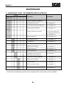
7.1 MAINTENANCE CHART - RECOMMENDED SERVICE INTERVALS
Break-In
(First 10)
HOURS
8
40 100 200
500
Procedure
Comments
X
Check all hardware for tightness
X
Check hydraulic oil level
See paragraph 7.3
X
Check all belts for proper alignment
See paragraph 7.8
Change engine oil and filter
See paragraph 7.4
X
Check hydraulic hoses for leaks
Use extreme caution when
checking the hydraulic hoses
See paragraph 2.5
X
Check coolant level
See paragraph 7.12
X
Check engine oil level
See paragraph 7.4
X
*Clean mower
See paragraph 7.14
X
Check condition of blades
See paragraph 7.9
X
Apply grease to fittings
See paragraph 7.2
X
Check tire pressure
See paragraph 7.10
X
Check coolant level
See paragraph 7.12
X
Check battery electrolyte level,
clean battery posts and cables
See paragraph 7.7
X
Check belts for proper alignment
See paragraph 7.8
X
Apply grease to fittings
See paragraph 7.2
X
Change engine oil
See paragraph 7.4
X
*Clean air cleaner element
See paragraph 7.6
X
Check lubricant in cutter deck gearbox
See paragraph 7.11
X
(First 5)
* Perform these maintenance procedures more frequently under extreme dusty or dirty conditions
25
Section 7
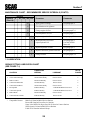
MAINTENANCE CHART - RECOMMENDED SERVICE INTERVALS (CONT'D)
Break-In
(First 10)
8
HOURS
40 100 200 500
Procedure
Comments
X
Apply grease to fittings
See paragraph 7.2
X
Check hardware for tightness
X
Change engine oil filter
See paragraph 7.4
X
Check hydraulic oil level
See paragraph 7.3
X
Replace engine fuel filter
See paragraph 7.5
X
Drain hydraulic system and
replace hydraulic oil
See paragraph 7.3
Use SAE 20W50
Motor Oil
X
Replace hydraulic oil filter
See paragraph 7.3
X
Replace cutter deck gearbox lubricant
See paragraph 7.1
X
Change coolant
See paragraph 7.12
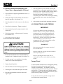
7.2 LUBRICATION
GREASE FITTING LUBRICATION CHART
(SEE FIGURE 7-1)
LUBRICATION
NO. OF
LOCATION
INTERVAL
LUBRICANT
PLACES
1
Caster Wheel Pivot
500 Hours/Yearly
Chassis Grease
2
2
Caster Wheel Bearings
100 Hours/Bi-Weekly
Chassis Grease
2
3
Brake Actuator
200 Hours/Monthly
Chassis Grease
2
4
Cutter Deck Bellcranks
40 Hours/Weekly
Chassis Grease
4
5
Cutter Deck Pusharms
100 Hours/Bi-Weekly
Chassis Grease
2
6
PTO Spindle
40 Hours/Weekly
+Lithium MP White Grease 2125
1
7
Cutter Deck Spindle
40 Hours/Weekly
+Lithium MP White Grease 2125
3
8
Brake Handle
200 Hours/Monthly
Chassis Grease
1
9
Cutter Deck Drive Shaft
40 Hours/Weekly
Chassis Grease
3
+
Compatible Greases:
Mobilix #2 found at Mobil Service Stations
Ronex MP found at Exxon Service Stations
Super Lube MEP #2 & Super Stay-M #2 found at Conoco Stations
Shell Alvania #2 found at Shell Service Stations
Lidok EP #2 found at industrial shops
26
Section 7
GREASE FITTING LUBRICATION
Lubricant Interval
Lithium MP White Grease 2125
(40 Hours/Weekly)
Chassis Grease
(100 Hours/Bi-monthly)
Chassis Grease
(200 Hours/Monthly)
Chassis Grease
(500 Hours/Yearly)
1
6
3
7
8
9
2
4
5
Figure 7.1 Lubrication Fitting Points
27
390S0145-1
Section 7
7.3 HYDRAULIC SYSTEM
B. Changing Hydraulic Oil
A. Checking Hydraulic Oil Level
The hydraulic oil should be changed after every 500
hours or annually, whichever occurs first. The oil should
also be changed if the color of the fluid has become black
or milky. A black color and/or a rancid odor usually
indicates possible overheating of the oil, and a milky
color usually indicates water in the hydraulic oil.
The hydraulic oil level should be checked after the first
10 hours of operation. Thereafter, check the oil after
every 200 hours of machine operation or monthly,
whichever occurs first.
-IMPORTANTIf the oil level is consistently low, check for
leaks and correct immediately.
-NOTEThe hydraulic oil should be changed if you
notice the presence of water or a rancid
odor to the hydraulic oil.
1. Wipe dirt and contaminants from around the
reservoir cap. Remove the cap from the hydraulic oil
reservoir.
1. Park the mower on a level surface and stop the
engine.
2. Visually check the level of hydraulic oil. Hydraulic
oil must be at least 3-1/4" inches from top of the
filler neck. If the level cannot be determined visually,
use a clean tape measure to check the level. If the
fluid is low, add 20W50 motor oil. DO NOT
overfill; (overfilling the oil reservoir may cause oil
seepage around the cap area).
2. Place a suitable container under the hydraulic oil
reservoir. Remove the fill cap from the reservoir.
Remove the drain plug from the bottom of the
reservoir. (See Figure 7-2). Allow the fluid to drain
into the container and properly discard it.
3. Re-install the drain plug into the reservoir and be
sure it is tight.
3. Clean the fill cap and install it onto the reservoir.
-NOTEBefore refilling the hydraulic oil reservoir
the hydraulic oil filter should be changed as
outlined in section C on the next page.
4. Fill the reservoir to 3-1/4" inches from the top of the
filler neck with 20W50 motor oil.
5. Replace the reservoir fill cap. Start the engine and
drive forward and backward for two minutes. Check
the oil level in the reservoir. If necessary, add oil to
the reservoir.
Hydraulic Oil
Reservoir
STT99HOR-1
Figure 7-2 Hydraulic Oil Reservoir
28
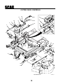
CUTTER DECK CONTROLS
41
20
45
42
8
21
36
19
16
46
18
44
22
40
4
6
2
37
10
42
17
14
43
5
41
35
23
3
9
41
41
11
40
33
34
26
29
32 38
30
41
27
40
41
22
28
13
40
40
41
25
28
15
39
39
41
31
26
40
29
24
40
12
24
26
41
1
CUTTER DECK
38
7
STT99CDC-1
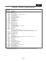
CUTTER DECK CONTROLS
Ref. Part
No. No.
1
2
3
4
5
6
7
8
9
10
11
12
13
14
15
16
17
18
19
20
21
22
23
24
25
26
27
28
29
30
31
32
33
34
35
36
37
38
39
40
41
42
43
44
45
46
04041-07
481764
481765
481766
04020-27
04020-28
04021-09
482429
43391
43487
43526
43527
45904
45905
04021-05
422381
423509
422346
46975
48100-14
481428
481522
422451
04020-09
04012-09
04040-09
04041-14
48114-04
04061-07
04021-10
04004-33
04067-05
04050-08
04021-07
04003-11
423463
04014-03
481547
48540
04001-20
04019-04
04050-10
04001-74
04003-04
04009-02
04019 -03
Description
Flatwasher, 3/8”
Link, Deck Lift
Rod End, Female - 1/2-20 RH
Rod End, Female - 1/2-20 LH
Nut, Jam 1/2-20 RH
Nut, Jam 1/2-20 LH
Nut, 3/8-16 Elastic Stop
Slide Weldment, Height Adjustment
Spacer, Decklift Pedal
Pin, Decklift
Swivel Joint, LH
Swivel Joint, RH
Bellcrank Weldment, LH Rear
Bellcrank Weldment, RH Rear
Locknut, 3/8-16 Center Lock
Guide, Short
Guide, Long
Lockplate, Decklift
Deck Latch (Includes items 20& 21)
Bushing, .502 ID.
Grip, Deck Latch
Spring, Helper (61” & 72” Cutter Decks Only)
Foot Pedal, Height Adjustment
Nut, Hex 5/8-11
Set Screw, 5/16-18 x 1/2" Sq. Head
Flatwasher, 5/8" (.656 x 1.312 x .095)
Flatwasher, 1" (1.062 x 1.50 x .048)
Grease Fitting
Cotter Pin, 3/16 x 1”
Nut, Hex Elastic Stop 5/16-18
Stud, 5/8-11 x 22.0"
Ring Pin, 1/2 x 3.30"
Ring, Retaining 1" External "E"
Nut, Hex Elastic Stop 1/2-13
Bolt, Carriage 3/8-16 x 1-1/4"
Bracket, Cutting Height Adjustment
Screw, Cap 5/16-18 x 3" FHHS
Lanyard, Deck Height Pin
Chain
Bolt, Hex Head 3/8-16 x 1-1/2"
Nut, Hex Serrated Flange 3/8-16
Ring, Retaining 1/2" External "E"
Bolt, Hex Head 1/2-13 x 3"
Bolt, Carriage 5/16-18 x 1"
Bolt, Shoulder 1/2 x 3/4"
Nut, Hex Serrated Flange 5/16-18
* Common hardware which should be purchased locally. All bolts Grade 5 plated, all other fasteners zinc plated.
39
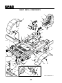
SHEET METAL COMPONENTS
52
51
53
1
11
6
15
16
10
13
14
17
46
9
A
12
48
5
47
57
7
3
19
A
48
26
8
15
4
22
28
23
45
15
50
56
15
27
31
32
30
12
33
33
29
25
34
36
24
35
20
37
38
54
49
43
55
41
39
18
40
18
42
49
40
56
20
2001 STTBSG-SMC-1
SHEET METAL COMPONENTS
Ref. Part
No. No.
1
2
3
4
5
6
7
8
9
10
11
12
13
14
15
16
17
18
19
20
21
22
23
24
25
26
27
28
29
30
31
32
33
34
451481
04001-09
451448
482147
48015
48903
421274
04003-12
421703
04029-01
04019-03
04003-01
48657
43584
04003-04
04021-09
04019-04
04017-27
451480
423489
04021-09
04001-19
04001-125
04021-13
481559
04021-20
481657
482028-01
Ref. Part
No. No.
Description
Fender Weldment, RH
Bolt, Hex Head, 5/16-18 x 1, Zinc
Spacer
Flatwasher,
Seat Plate Weldment
Seat Assembly w/armrest
Bolt
Nut
Battery
Pad, Battery Cover
Cover, Battery
Bolt, Carriage 5/16-18 x 3/4"
Plate, Battery Box
Wing Nut, 1/4-20 x 3/4"
Nut, Hex Serrated Flange 5/16-18
Bolt, Carriage 1/4-20 x 6"
Rubber Pad
Spacers
Bolt, Carriage 5/16-18 x 1"
Seal
Lock Nut, 3/8-16, Elast. Stop
Main Frame
Nut, Hex Serrated Flange 3/8-16
Screw, Hex Serrated Flange 3/8-16 x 1"
Fender Weldment, LH
Foot Plate
Nut, Hex Elastic Stop 3/8-16
Bolt, Hex Head 3/8-16 x 1-1/4"
Bolt, Hex Head 5/8-11 x 4"
Nut, Hex Elastic Stop 5/8-11
Cap, Grease
Nut, Hex Elastic Stop 1.0-14
Bearing W/Race
Plug, 1/4-28 THD Form
35
36
37
38
39
40
41
42
43
44
45
46
47
48
49
50
51
52
53
54
55
56
57
45936
45937
45939
451128
481025
04021-07
45934
04001-134
43581
481551
481613
481612
04041-07
481284
48566
04001-59
04019-02
481846
482341
482342
482344
482343
481770
48114-06
04001-71
481825
Description
Extention Weldment, Caster 52A (LH)
Extention Weldment, Caster
52A (RH) & 61A (LH &RH)
Extention Weldment, Caster 72A (LH)
Extention Weldment, Caster 72A (RH)
Seal, 2.00 OD. x 1.625 Bore
Nut, Hex Elastic Stop 1/2-13
Yoke Weldment, Caster
Bolt, Hex Head 1/2-13 x 7-1/2"
Sleeve
Wheel Assy (Inc.items 42,43 & 55 thru 57)
Tire
Rim Assembly (Includes item 55)
Washer, 3/8’
Bumper, Rubber
Cable, Seat Stop
Bolt, Hex Head 1/4-20 x 1-1/4"
Nut, Hex Serrated Flange 1/4-20
Roller Bearing
Caster Wheel Assy (Inc. 31 thru 47)
52A (RH) & 61A (LH &RH)
Caster Wheel Assy (Inc. 31 thru 47)
52A (LH)
Caster Wheel Assy (Inc. 31 thru 47)
72A (LH)
Caster Wheel Assy (Inc. 31 thru 47)
72A (RH)
Back Cushion Cover
Seat Cushion Cover
Arm Rest, Both Sides
Arm Rest Cover
Bearing, Oilite
Grease Fitting
Bolt, Hex Head, 1/2-13 x 1.5”
Footrest
* Common hardware which should be purchased locally. All bolts Grade 5 plated, all other fasteners zinc plated.
41
DECK DRIVE COMPONENTS
12
15
4
13
31
32
13
33
12
17
35
15
30
11
1
34
36
2
19
13
35
21
5
18
40
20
41
29
42
44
38
4
11
37
6
TO
ENGINE
FLYWHEEL
3
16
45
8
50
24
28
10
25
35
43
54
55
24
27
63
5
44
26
57
52 51
60
58
43
45
27
40
43 To A
53
43
25
42
47
To B
7
61
59
46
23
22
TO 9
REAR
OF
ENGINE
35
43
39
43
22
A B
64
55
35
68
40 59
16
42
74
69
73
71
70
67
14
66
73
62
72
42
48
99STTBSG-DDC-1
DECK DRIVE COMPONENTS
Ref. Part
No. No.
1
2
3
4
5
6
7
8
9
10
11
12
13
14
15
16
17
18
19
20
21
22
23
24
25
26
27
28
29
30
31
32
33
34
35
36
37
Description
422845
481531
481309
04003-07
04019-02
04010-01
04031-01
04020-01
451080
43506
48114-04
Belt Guard, Rear
Hinge, Rear Belt Guard
Latch, Hood
Carr. Bolt 1/4-20 x .5”
Nut, Serr. Flg. 1/4-20
Screw, #10-32 x .5, Phillips Head
Lock Washer, #10
Nut, #10-32
Weldment, Pump Mounting
Spacer, Engine
Grease Fitting 1/4-28 Self Tapping
Rod, Anti-Rotation
Lockwasher
Plate
04001-20 Bolt, Hex Head 3/8-16 x 1.50”
46977
Spindle Assembly, Deck Drive
461399
Clutch, Electric PTO
481398
Pulley, 6.35” dia. Tapered Bore
481536
Hub, Tapered 1” dia.
04063-06 Key, 1/4 x 1/4 x 1.5”
04001-10 Bolt, Hex Head 5/16-18 x 1.25”
481883
Pulley, 6.25” OD, Tapered
481788
Pulley, 5.45” OD
04012-04 Set Screw, 5/16-18 x .375”
481884
Hub, Tapered 17mm Bore
04001-01 Bolt, Hex Head 1/4-20 x .75”
04063-27 Key, 5mm x 5mm x 30mm
481461
Belt, Pump Drive
481460
Belt, Deck Drive
04063-11 Key, 1/4 x 1/4 x 2.5”
04001-101 Bolt, Hex Head 7/16-20 x 2.5”
04030-05 Lock Washer 7/16”
04041-28 Flat Washer 7/16 x .469 x 1.75 x .25”
04001-109 Bolt, Hex Head 1/4-20 x 1.375”
04021-09 Nut, Elastic Stop 3/8-16
04041-07 Flat Washer 3/8, .391 x .938 x .105”
04063-20 Key, 1/4 x 1/4 x 1.00”
Ref. Part
No. No.
Description
38
39
40
41
42
43
44
45
46
47
48
49
50
51
52
53
54
55
56
57
58
59
60
61
62
63
64
65
66
67
68
69
70
71
72
73
74
Idler Arm
Bolt, Hex Head 3/8-16 x 2.25”
Nut, Serr. Flg. 3/8-16
Pulley, PTO Idler
Bolt, Hex Head 3/8-16 x 1.5” Grade 8
Flat Washer 3/8” Grade 8
Spring
Bearing
Pivot, Idler - Short
Bolt, Hex Head 3/8-16 x 2.5”
Relief Fitting
Bolt, Hex Head 5/16-18 x 1.00”
Idler Arm
Pulley, Pump Idler
Spacer
Bolt, Hex Head 3/8-16 x 3.75” Grade 8
Lock Washer 3/8” .638 x .380 x .094”
Nut 3/8-16
Nut, Elastic 3/8-16
Pivot, Idler - Long
Bolt, Hex Head 3/8-16 x 3.00”
Nut, Elastic 5/16-18
Bolt, Hex Head 5/16-18 x 3.00”
Lock Washer 5/16”
Spindle Housing
Bumper, Rubber
Nut, Serr. Flg. 5/16-18
Bolt, Hex Head 3/8-16 x 1.00”
Clamp, Wire
Bolt, Carr. 5/16-18 x .75”
Driveshaft
Spacer, Inside
Bushing
Seal, 2.00 OD x 1.625 Bore
Nut, 1.06-18
Roller Bearing Assembly
Spacer, Outside
461079
04001-46
04019-04
48181
04001-136
04043-04
481522
48224
43503
04001-31
48677
04001-09
481756
48198
43277
04001-138
04030-04
04020-04
04021-05
43504
04001-54
04021-10
04001-49
04030-03
43294
481284
04019-03
04001-19
48030-09
04003-12
481785
43296
43297
481025
481035
481022
43312
* Common hardware which should be purchased locally. All bolts Grade 5 plated, all other fasteners zinc plated.
43
RADIATOR, COOLERS & ENGINE BRACKETS
41
42
36
17
36
31
40
26
26
22
15
9
28
2
43
26
16
3
21
44
45
1
14
12
20
19
16
30
13
24
TO "A"
18
11
33
10
42
14
4
ATTACHES
TO
FRAME
5
25
26
23
7
26
29
A
10
39
35
8
37
6
34
27
32
26
38
37
2k STTBSG-RCEB-1
44
RADIATOR, COOLERS & ENGINE BRACKETS
Ref. Part
No. No.
1
2
3
4
5
6
7
8
9
10
11
12
13
14
15
16
17
18
19
20
21
22
23
24
25
26
27
28
29
30
31
32
33
34
35
36
37
38
39
40
41
42
43
44
45
481810
481742
481743
04030-03
422701
422697
422698
422702
422704
422696
481818
481816
481750
48136-09
422703
48136-12
422736
451120
451121
48633
481827
451083
451082
481795
**
04003-12
04019-03
04069-02
04090-04
481817
481924
**
43508
04002-12
482505
422715
481284
04001-08
423524
423525
48136-13
04001-11
04017-16
04003-04
04002-10
04040-15
04021-10
Description
Radiator
Hose, Upper Radiator
Hose, Lower Radiator
Lockwasher, 5/16 (.317 x .586 x .078) Helical Spring
Bracket, Air Cleaner
Bracket, Engine Mounting LH
Bracket, Engine Mounting RH
Bracket, Radiator Mounting
Shroud, Radiator
Plate, Engine Mounting
Indicator, Air Cleaner
Pre-Cleaner, Engine Air
Hose, Air Intake
Clamp, Hose (2.25” Dia.)
Hinge, Hood
Clamp, Hose (1.50” Dia.)
Bracket, Hood Support
Bracket, Exhaust Support
Clamp Weldment, Muffler (Clamp and Weldment)
Clamp, Muffler (Clamp Only)
Elbow, Exhaust
Screen, Debris
Hood
Engine, Briggs & Stratton 31 HP
(Spec. # 580447-0116-E2) Not Available Through Scag, Contact Briggs & Stratton)
Air Cleaner Assembly w/ Mounting Band (Not Available Through Scag, Contact Briggs & Stratton)
Bolt, Carr. 5/16-18 x .75”
Nut, Serr. Flng 5/16-18
Pin, Rue Cotter 1/2” dia.
Rivet, Pop 1/8 x .294”
Pad, Radiator
Adaptor, Pre-Cleaner
Coolant Tank Assembly w/Hose (Not Available Through Scag, Contact Briggs & Stratton)
Spacer, Radiator
Bolt, Hex Head M8 x 20MM LG
Cooler, Oil
Engine Spacer
Bumper, Rubber
Bolt, Hex Head 5/16-18 x .75”
Mounting Bracket, LH, Oil Cooler
Mounting Bracket, RH, Oil Cooler
Hose Clamp, 0.69” Dia. (4)
Bolt, Hex Head 5/16-18 x 1.50”
Bolt, Hex Head 5/16-18 x .75 Serrated Flange
Bolt, Carrage 5/16-18 x 1.0”
Nut, 5/16-18 Elastic Stop
Flatwasher, 5/16 (.375 x .875 x .083)
Nut, 5/16-18 Elastic Stop
* Common hardware which should be purchased locally. All bolts Grade 5 plated, all other fasteners zinc plated.
** Purchase through Briggs & Stratton.
45