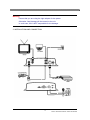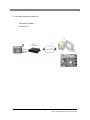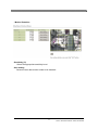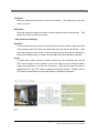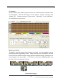
1
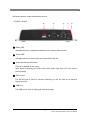
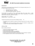
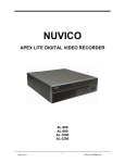
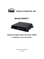
HOME AUTOMATION, INC. Model 68A00-1 Network Digital Video Recorder (DVR) Installation and User Guide Document Number 68I00-1 Rev. A January, 2008 CONTENT VERIFICATION Before installing the Network Digital Video Recorder, please make sure that the following items are included in the box: 1. Network Digital Video Recorder 2. Crossover LAN cable 3. DC 5V / 1.5 A Power Adapter 4. Terminal Block 5. Client Software CD 6. This Instruction Manual 1 68A00-1 NETWORK DIGITAL VIDEO RECORDER DISCLAIMER • While every effort has been made to ensure that the information contained in this guide is accurate and complete, no liability can be accepted for any errors or omissions. • HAI reserves the right to change the specifications of the hardware and software described herein at any time without prior notice. • No part of this guide may be reproduced, transmitted, transcribed, stored in a retrieval system, or translated into any language in any form, by any means, without prior written permission of HAI. • HAI makes no warranties for damages resulting from corrupted or lost data due to mistaken operation or malfunction of the Network Digital Video Recorder, the software, the hard drives, personal computers, peripheral devices, or unapproved/unsupported devices. Trademark Acknowledgements • DiamondMax Plus 9, DiamondMax 16, MaxLine II and MaxLine Plus II are a trademark of Maxtor Corporation. • Barracuda series HDDs are a trademark of Seagate Corporation. • Microsoft, Windows98, Windows ME, Windows NT, Windows XP, Internet Explorer are either registered trademarks or trademarks of Microsoft Corporation in the United States and/or other countries. • Other names and products not mentioned above may be registered trademarks or trademarks of their respective companies. 2 68A00-1 NETWORK DIGITAL VIDEO RECORDER FCC NOTICE Network Digital Video Recorder, Model 68A00-1: This device complies with Part 15 of the FCC Rules. Operation is subject to the following two conditions; 1. This device may not cause harmful interference, and 2. This device must accept any interference received, including interference that may cause undesired operation. Note: This equipment has been tested and found to comply with the limits for Class B digital devices, pursuant to Part 15 of the FCC rules. These limits are designed to provide reasonable protection against harmful interference in a residential installation. This equipment generates, uses and can radiate radio frequency energy and, if not installed and used in accordance with the instructions, may cause harmful interference to radio communications. However, there is no guarantee that interference will not occur in a particular installation. If this equipment does cause harmful interference to radio or television reception, which can be determined by turning the equipment off and on, the user is encouraged to try to correct the interference by one or more of the following measures: • Reorient or relocate the receiving antenna. • Increase the separation between the equipment and receiver. • Connect the equipment into an outlet on a circuit different from that to which the receiver is connected. • Consult the dealer or an experience radio/TV technician for help. Do not make any changes or modifications to the equipment unless otherwise specified in the manual. If such changes or modifications should be made, you could be required to stop operation of the equipment. Home Automation, Inc. 4330 Michoud Blvd. New Orleans, LA 70129 Tel: (504) 736-9810 Canadian Radio Interference Regulations THIS CLASS B DIGITAL APPARATUS MEETS ALL REQUIREMENTS OF THE CANADIAN INTERFERENCE CAUSING EQUIPMENT REGULATIONS. 3 68A00-1 NETWORK DIGITAL VIDEO RECORDER Read this First Test Sessions Before you try to record important subjects, we highly recommend that you make several test recording and playback sessions to ensure that the Network Digital Video Recorder is operating and being operated correctly. Please note that HAI, its subsidiaries and affiliates, and its distributors are not liable for any consequential damages arising from any malfunction of a Network Digital Video Recorder or its accessories, including the hard disk drive, compact flash, and USB thumbnail drive, which result in the failure of an image to be recorded or to be recorded in a format that is machine sensible. The Privacy act of 1974 (5 U.S.C. § 552a) Please note that HAI Network Digital Video Recorders are intended for monitoring and surveillance use and should never be used in a manner that invades other people’s privacy or contravenes international or domestic privacy act and its regulations. Please be advised that in certain cases the recording of individuals, private properties, or commercial properties by means of camera or other devices may contravene legal rights of such individuals even if the images were recorded for personal use. Warranty Limitations This Network Digital Video Recorder’s warranty is only effective in the country of sale. If a problem arises while the VIDEO SERVER is in use abroad, please convey it back to the country of sale before proceeding with a warranty claim to HAI customer help desk. 4 68A00-1 NETWORK DIGITAL VIDEO RECORDER SAFETY PRECAUTIONS • Before using the Network Digital Video Recorder, please ensure that you read and understand the safety precautions described below. Always ensure that the Network Digital Video Recorder is operated correctly. • The safety precautions noted on the following pages are intended to instruct you in the safe and correct operation of the Network Digital Video Recorder and its accessories to prevent injuries or damage to the self, other persons and equipment. • In this Instruction Manual, the term “Network Digital Video Recorder”, “68A00-1”, “equipment”, and “device” refers primarily to the Network Digital Video Recorder and its accessories such as power supply. WARNING • Do not cover the ventilation opening or slots on the outer casing. To prevent the Network Digital Video Recorder from overheating, provide at least two inches of air space around the vent and the slots. • Do not drop metallic parts through slots. This could permanently damage the Network Digital Video Recorder. Immediately turn the device’s power off or unplug the power cord from the power outlet. Contact a qualified service personnel authorized by the equipment distributor or a HAI customer help desk. • Do not attempt to disassemble or alter any part of the equipment that is not expressly described in this guide. Disassembly or alteration may result in high voltage electrical shock. Internal inspections, alterations and repairs should be conducted by qualified service personnel authorized by the equipment distributor or HAI customer help desk. • Stop operating the equipment immediately if it emits smoke or noxious fumes. Failure to do so may result in fire or electrical shock. Immediately turn off power to the equipment and remove the power cable from the power outlet. Confirm that smoke and fume emissions have ceased. Please consult the Network Digital Video Recorder distributor or the closest HAI customer help desk. • Stop operating the equipment if a heavy object is dropped or the casing is damaged. Do not strike or shake. Failure to do so may result in fire or electrical shock. Immediately turn the Network Digital Video Recorder’s power off or unplug the power cord from the power outlet. Please consult the Network Digital Video Recorder distributor or the closest HAI customer help desk. 5 68A00-1 NETWORK DIGITAL VIDEO RECORDER • Do not allow the equipment to come into contact with, or become immersed in, water or other liquids. Do not allow liquids to enter the interior. The Network Digital Video Recorder has not been waterproofed. If the exterior comes into contact with liquids or salt air, wipe it dry with a soft, absorbent cloth. In the event that the water or other foreign substances enter the interior, immediately turn the Network Digital Video Recorder’s Power off or unplug the power cord from the power outlet. Continued use of the equipment may result in fire or electrical shock. Please consult the Network Digital Video Recorder distributor or the HAI customer help desk. • Do not use substances containing alcohol, benzene, thinners or other flammable substances to clean or maintain the equipment. The use of these substances may lead to fire. Use a dry cloth on a regular periodic basis and wipe away the dust and dirt that collects on the device. In dusty, humid or greasy environments, the dust that collects around the ventilation or the slots on the outer casing over long periods of time may become saturated with humidity and short-circuit, leading to fire. • Do not cut, damage, alter or place heavy items on the power cord. Any of these actions may cause an electrical short circuit, which may lead to fire or electrical shock. • Do not handle the device or power cord if the hands are wet. Handling it with wet hands may lead to electrical shock. When unplugging the cord, ensure that you hold the solid portion of the plug. Pulling on the flexible portion of the cord may damage or expose the wire and insulation, creating the potential for fires or electrical shocks. • Use only the recommended power accessories. Use of power sources not expressly recommended for this equipment may lead to overheating, distortion of the equipment, fire, electrical shock or other hazards. • Do not place the battery near a heat source or expose it to direct flame or heat. Neither should you immerse them in water. Such exposure may damage the battery and lead to the leakage of corrosive liquids, fire, electrical shock, explosion or serious injury. • Do not attempt to disassemble, alter or apply heat to the battery. There is serious risk of injury due to an explosion. Immediately flush with water any area of the body, or clothing that comes into contact with the inner contents of the battery. If the eyes or mouth contact these substances, immediately flush with water and seek medical assistance from a medical professional. • Avoid dropping or subjecting the battery to severe impacts that could damage the casings. It could lead to leakage and injury. • Do not short-circuit the battery terminals with metallic objects, such as key holders. It could lead to overheating, burns and other injuries. 6 68A00-1 NETWORK DIGITAL VIDEO RECORDER • The supplied power supply and power cord are designed for exclusive use with the Network Digital Video Recorder. Do not use it with other products or battery. There is a risk of fire and other hazards. CAUTION • Avoid using, placing or storing the equipment in places subject to strong sunlight or high temperatures, such as the greenhouse or trunk of a car. Exposure to intense sunlight and heat may cause the battery to leak, overheat or explode, resulting in fire, burns or other injuries. High temperatures may also cause deformation of the casing. Ensure that there is good ventilation when using the equipment. • Do not store the equipment in humid or dusty areas. Storage in such areas could lead to fire, electrical shock or other damage. • Do not operate the Network Digital Video Recorder beyond its specified temperature, humidity or power source ratings. Do not use the Network Digital Video Recorder in an extreme environment such as in high temperature or high humidity. Use the device at temperatures within 41°F - 104°F and humidity below 90 %. The normal operating power source for this device is 110V-220V AC 50/60Hz. PREVENTING MALFUNCTION • Avoid Strong Magnetic Fields. Never place the Network Digital Video Recorder in close proximity to electric motors or other equipment generating strong electromagnetic fields. Exposures to strong magnetic fields may cause malfunctions or corrupt image data. • Avoid Condensation Related Problems. Moving the equipment rapidly between hot and cold temperatures may cause condensation (water droplets) to form on its external and internal surfaces. You can avoid this by placing the equipment in an airtight, resealable plastic bag and letting it adjust to temperature changes slowly before removing it from the bag. • If Condensation forms inside the Network Digital Video Recorder, stop using the equipment immediately. Continued use may damage the equipment. Remove the power cord from the power outlet and wait until the moisture evaporates completely before resuming use. 7 68A00-1 NETWORK DIGITAL VIDEO RECORDER Warnings Open the cover at your own discretion. or electric shock. product. Doing so can cause system damage Contact a qualified technician or your dealer for repair of this Manufacturer is not responsible for any damage or injury sustained by opening and/or assembling/disassembling the unit. Electric shock or fire may result when foreign liquids or substances are introduced into the unit. If this occurs, discontinue use, power down the unit and contact your dealer immediately. This equipment is susceptible to electric surge damage. Use of a conditioned power supply is recommended. Avoid installing the unit in locations where severe vibration, high humidity or direct sunlight exists. Do not place a heavy load on top of this unit. Danger of explosion if battery is incorrectly replaced. Replace the battery only with the same type recommended by the manufacturer. Dispose of used batteries according to the manufacturer's instructions. 8 68A00-1 NETWORK DIGITAL VIDEO RECORDER Table of Contents CONTENT VERIFICATION........................................................................................................... 1 DISCLAIMER ................................................................................................................................ 2 FCC NOTICE................................................................................................................................. 3 Canadian Radio Interference Regulations................................................................................ 3 Read this First.............................................................................................................................. 4 Test Sessions..................................................................................................................... 4 The Privacy act of 1974 (5 U.S.C. § 552a)........................................................................ 4 Warranty Limitations ......................................................................................................... 4 SAFETY PRECAUTIONS ............................................................................................................. 5 WARNING ..................................................................................................................................... 5 CAUTION ...................................................................................................................................... 7 PREVENTING MALFUNCTION.................................................................................................... 7 1. FRONT LAYOUT ........................................................................................................... 11 2. REAR LAYOUT.............................................................................................................. 12 3. INSTALLATION AND CONNECTION............................................................................ 13 3.1 One-way monitoring using a PC ............................................................................. 14 I. Introduction............................................................................................................................. 15 1. Network Digital Video Recorder .................................................................................... 15 2. About the 68A00-1......................................................................................................... 15 3. Main Features................................................................................................................ 16 II. Installation.............................................................................................................................. 18 1. Connect the 68A00-1 to a configuration PC:................................................................. 18 1.1 Select a PC or laptop running any Microsoft Windows OS, with: ........................... 18 1.2 Connecting the 68A00-1 to a configuration PC: ..................................................... 18 2. Assign an IP address to the 68A00-1 using IP Setup wizard ........................................ 18 2.1 Run IP Setup wizard ............................................................................................... 18 2.2 Browsing the 68A00-1 unit...................................................................................... 19 2.3. Confirm communications ....................................................................................... 21 3. Setup of the 68A00-1..................................................................................................... 21 III. Real-time Video Monitoring................................................................................................. 22 1. Accessing the 68A00-1 Server ...................................................................................... 22 1.1 Auto-installation of the Client Viewer Program ....................................................... 22 1.2 User Login............................................................................................................... 23 9 68A00-1 NETWORK DIGITAL VIDEO RECORDER 2. The 68A00-1 Viewer ...................................................................................................... 25 2.1 Image Display Panel ............................................................................................... 25 2.2 Video Control Panel ................................................................................................ 26 2.4 Go to Admin page ................................................................................................... 29 2.5 Audio mute .............................................................................................................. 29 2.6 Transfer to 68A00-1 Player..................................................................................... 29 IV. Search and Playback ........................................................................................................... 30 1. Remote Playback .......................................................................................................... 30 2. Login .............................................................................................................................. 30 3. 68A00-1 Player .............................................................................................................. 31 3.1 Image Display Panel ............................................................................................... 31 3.2 The time-map Panel and intelligent playback ......................................................... 32 3.3 Playback Control Panel .......................................................................................... 33 3.4 Calendar Panel ....................................................................................................... 33 3.5 Storage gauge......................................................................................................... 34 3.6 Search, Backup, and Print ...................................................................................... 34 3.7 File List Panel ......................................................................................................... 35 3.8 View Channel Mode Selection Panel...................................................................... 36 3.9 Configuration........................................................................................................... 36 3.10 Go to the Administrator’s Page ............................................................................. 37 3.11 Go to the 68A00-1 Viewer..................................................................................... 37 V. Setup ...................................................................................................................................... 38 1. Connect to the Administration Page .............................................................................. 38 2. Management of System Setup ...................................................................................... 39 2.1 General Settings ..................................................................................................... 39 2.2 Video Settings......................................................................................................... 42 2.3 Audio Settings ......................................................................................................... 45 2.4 Pan/Tilt/Zoom (PTZ) Setup ..................................................................................... 46 2.5 Schedule ................................................................................................................. 48 2.6 Network Settings..................................................................................................... 52 2.7 Registration (to directory server) ............................................................................ 55 2.8 D/O control (Relay Control) .................................................................................... 57 2.10 Configuration Import/Export.................................................................................. 58 2.11 Software Update ................................................................................................... 59 2.12 Restart................................................................................................................... 60 Appendix 1: Troubleshooting................................................................................................... 61 10 68A00-1 NETWORK DIGITAL VIDEO RECORDER NETWORK DIGITAL VIDEO RECORDER LAYOUT 1. FRONT LAYOUT ⑤ ① ④ ③ ① ② Ready LED Indicates the unit is completed initialized and is ready to be accessed. ② On Air LED Indicates that one or more users are connected to the unit. ③ Audio Input/Output Connector Connect a speaker to the output. Input allows connecting an audio device with audio input level of 0.2-2V (line-in level normally). ④ RS-232 port The RS-232 port is used as console monitoring or can be used as an external signal input port. ⑤ USB port The USB port is used for flash-type external storage. 11 68A00-1 NETWORK DIGITAL VIDEO RECORDER 2. REAR LAYOUT ⑤ ④ ③ ② ① ① Power Input connector (DC 5V) * Please check the voltage of your connecting adapter. ② Ethernet port (10/100 Base-T Ethernet) ③ Data I/O connector Sensor Input connector (S1, G, S2): Connect up to 2 dry contact input sensors. Data Output (DO) connector (NC, NO, COM): Normally Open (NO) type or Normally Close (NC) type may be used. RS-485(+, -): Connect pan, tilt, and zoom available camera or unit. ④ Video Out One channel composite video output is supported. ⑤ Input connectors Camera signal inputs: Camera signal type (NTSC or PAL) can be adjusted on administrator’s page. 12 68A00-1 NETWORK DIGITAL VIDEO RECORDER Warning: Ensure that you are using the right adapter for the power. Otherwise, fatal damage will be caused to the unit. In such case, HAI is NOT responsible for the damage. 3. INSTALLATION AND CONNECTION 13 68A00-1 NETWORK DIGITAL VIDEO RECORDER 3.1 One-way monitoring using a PC Transmitter: 68A00-1 Receiver: PC 14 68A00-1 NETWORK DIGITAL VIDEO RECORDER I. Introduction 1. Network Digital Video Recorder The 68A00-1 Network Digital Video Recorder is a device that transmits video and audio data via network in real-time. The server converts the analog video signals and audio signals into digital data and compresses them for on-line transmission. Since the server has a built-in web server and network interface, it may not require additional hardware, software, or programming (besides configuring IP address) to view live video transmissions. After connecting all the cameras to the Network Digital Video Recorder and configuring its IP address, the Network Digital Video Recorder can be accessed from anywhere with an Internet connection. 2. About the 68A00-1 The 68A00-1 is a 4 channel Network Digital Video Recorder that transmits video in high resolution with bi-directional audio in real-time via the network. The 68A00-1 supports various network environments such as high-speed Internet, cable, DSL, LAN, or WAN. The 68A00-1 compresses video in MPEG4, which is 4 to 5 times more than still image compression algorithms such as JPEG or Wavelet. This allows more efficient monitoring through low bandwidth networks such as DSL, DHCP, and Cable network. The 68A00-1 provides the high-performance interactive audio transmission capability using an ADPCM Codec. The 68A00-1 can transmit audio using a microphone or PC headset. 15 68A00-1 NETWORK DIGITAL VIDEO RECORDER 3. Main Features The 68A00-1 is designed for various applications, such as IT related applications, remote monitoring, and Internet broadcasting with the user friendly interface. Highly Efficient MPEG4 Video Compression The 68A00-1 support a 4 to 5 times more efficient transmission compared to similar products based on the existing still image compression methods (JPEG and Wavelet). Under the same conditions, if the size of motion pictures and audio by still image compression method is 7.0 - 8.0 Kbytes, the 68A00-1 based on MPEG4, compresses images up to 1.5 – 2.0 Kbytes (320 x 240) per frame. It is transmitted at 15 - 20 frames per second via 256Kbps bandwidth, and 30 frames per second via 512Kbps bandwidth or higher. However, the image sizes can vary depending on actual field conditions. Interactive Audio In addition to the real-time motion picture and audio transmission, the 68A00-1 provides an interactive audio transmission function. To provide more precise information at the location, the 68A00-1 Network Server allows users to hear audio and to watch video images simultaneously from the remote location where the 68A00-1 server is installed. Interface to External Equipment The 68A00-1 Network Digital Video Recorder supports pan/tilt/zoom camera devices, alarm sensors, as well as other security equipment to customize the monitoring system. Various Network Environments The 68A00-1 supports various network connections (such as LAN, WAN, Cable, DSL, etc.) that are utilizing either Static IP or Dynamic IP address services. 16 68A00-1 NETWORK DIGITAL VIDEO RECORDER Local Recording and Playback The internal hard drive provides the total security solution via network. 68A00-1 stores live video and audio on its local drive. The You can search and playback files at any time and anywhere network access is available. The features of Local recording and playback are as follows: - Simultaneous recording, search, playback, and backup operation of 16 channels - Weekly schedule - Audio synchronized recording - Continuous, Motion, Sensor, Video loss, and Network disconnection recordings - Thumbnail playback - User friendly full web environment 17 68A00-1 NETWORK DIGITAL VIDEO RECORDER II. Installation This chapter covers installation of the 68A00-1 Network Digital Video Recorder on Static IP environments. Refer to Chapter 5 for more information about the installation on Dynamic IP environments. 1. Connect the 68A00-1 to a configuration PC: 1.1 Select a PC or laptop running any Microsoft Windows OS, with: • A 10baseT Ethernet adapter or PCMCIA card • A crossover LAN cable (to direct connect to the 68A00-1), or 2 network patch cables (for connection via a router or switch) • Microsoft Internet Explorer 4.0 or higher with Active-X Control Plug-In 1.2 Connecting the 68A00-1 to a configuration PC: • Connect the crossover cable between the PC and the Ethernet port on 68A00-1, or • Connect the PC and the 68A00-1 to a router or switch 2. Assign an IP address to the 68A00-1 using IP Setup wizard 2.1 Run IP Setup wizard Run the ‘IPSetup.exe’ utility, which can be found on supplied Surveillance Utilities CD (68A07-1), on a PC that is on THE SAME SUBNET. 18 68A00-1 NETWORK DIGITAL VIDEO RECORDER 2.2 Browsing the 68A00-1 unit Click the ‘Search’ button to detect the 68A00-1 unit on the same subnet. The 68A00-1 will be shown with its MAC Address, the factory default IP Address, Subnet Mask, and Gateway, as seen below: IP Address: 192.168.1.2 Subnet Mask: 255.255.255.0 Gateway: 192.168.1.1 Select the 68A00-1 to be installed and set the IP address, subnet mask, default gateway and administrator’s password (that is set as ‘pass’ for factory default) followed by clicking the ‘Set’ button. 19 68A00-1 NETWORK DIGITAL VIDEO RECORDER When changing ‘Http Port’ or ‘Streaming Port’, it is necessary to restart the Unit by clicking ‘Restart the server’. The value of ‘Streaming Port’ has to be set with a modulo of 10 plus 1 (e.g. 7011, 7021, 7031, etc.). 20 68A00-1 NETWORK DIGITAL VIDEO RECORDER 2.3. Confirm communications To confirm communications, click the ‘Ping test’ button. Confirmation of communications should look similar to the following: Reply from 192.168.1.2: byte=32 time=2ms TTL=225 Reply from 192.168.1.2: byte=32 time=2ms TTL=225 Reply from 192.168.1.2: byte=32 time=2ms TTL=225 Reply from 192.168.1.2: byte=32 time=2ms TTL=225 Communication failure would look similar to the following: Request timed ‘OUT’ Request timed ‘OUT’ Request timed ‘OUT’ Request timed ‘OUT’ Ping statistics for 192.168.1.2: If some, or all, of the packets are lost, repeat the ‘ping’ command again. If you keep getting the ‘Request timed Out’’ message, check the following: • The 68A00-1 is connected to power and turned on. • Cable connections (between 68A00-1 and PC) or (68A00-1, PC, and HUB). • IP addresses assigned to the 68A00-1 and PC are in the same subnet mask. After confirming the items above, rerun IP Setup and reassign the IP to the 68A00-1. 3. Setup of the 68A00-1 Access the 68A00-1 admin page to set the 68A00-1 operational configurations. • In the IP Setup program, click the ‘Launch admin page’ button or • Open Internet Explorer. • Enter the IP address in the URL box in the browser as below: http://(IP address)/admin_login.html For example: http://192.168.1.2/ admin_login.html The default ID is “admin” and password is “pass”. It is strongly recommended that you change the ID & Password to prevent anonymous connections. For further information, please refer to Chapter 5. 21 68A00-1 NETWORK DIGITAL VIDEO RECORDER III. Real-time Video Monitoring 1. Accessing the 68A00-1 Server Run Internet Explorer 4.0 or higher on the PC, and enter the IP address of the 68A00-1 unit into the address bar. 1.1 Auto-installation of the Client Viewer Program When initially accessing the 68A00-1 home page, the client viewer software is automatically downloaded and installed to allow you to view the MPEG-4 video images. As noted in Chapter 3, the Active-X Control Plug-In should have been installed on the browser. If it is not installed, the following installation prompt may appear. <Active-X for 68A00-1 Viewer> <Active-X for 68A00-1 Player> 22 68A00-1 NETWORK DIGITAL VIDEO RECORDER <Active-X for Schedule setting> If video is not displayed, ensure that the camera and network cables are properly connected on 68A00-1 unit. If trouble persists, please refer to Troubleshooting in Appendix 1. 1.2 User Login The default login for users is ’guest’ for both ID and Password. The system administrator can modify the ID and Password and assign an individual ID and Password to each user. The login page allows the user to choose between the 68A00-1 Viewer and the 68A00-1 Player. The 68A00-1 Viewer allows users to access live monitoring and viewer controls. The 68A00-1 Player allows users to access file playback which is described in detail in the next chapter. 2. After power-up, the READY LED should be lit. 3. Connect to the 68A00-1 via the browser as follows: a. Open Internet Explorer. b. Enter the IP address in the address bar of the browser as shown below: http://(IP address) For example: http://192.168.1.2 When connected, the On-Air LED should be lit. 23 68A00-1 NETWORK DIGITAL VIDEO RECORDER The 68A00-1 user’s log in page will be displayed. The Default Guest Account ID and Password are both “guest”. <Main Login Window> NOTE: The 68A00-1 browser interface requires the Active-X Control Plug-In for Internet Explorer. If the Active-X Control Plug-In is not installed, you will be prompted to install the plug-in before the 68A00-1 interface is launched. answer “YES” to the questions about installation of the plug-in. You must After installation, the 68A00-1 browser interface should be displayed. 24 68A00-1 NETWORK DIGITAL VIDEO RECORDER 2. The 68A00-1 Viewer When the installation of the client program is complete and your login is accepted, the 68A00-1 Viewer is automatically connected and begins displaying video. <68A00-1 Viewer> 2.1 Image Display Panel The image display panel can display up to 4 channels. of 320x240. Each channel has a resolution The display panel has the following components. Title Bar Displays the title of the channel as entered in Administration. Status Display Bar Displays the current time and date at the server site, and the number of clients connected 25 68A00-1 NETWORK DIGITAL VIDEO RECORDER Title Bar <Status Display Bar> 2.2 Video Control Panel The control panel allows the user to control camera options. Camera Selection Camera Selection allows you to selects a single channel for view/display. View Selection View selection allowsyou to configure the channel display mode. 26 68A00-1 NETWORK DIGITAL VIDEO RECORDER Single channel display Displays the selected channel. Quad channel display Displays 4 channels simultaneously. Full screen display Zooms in the single channel to fill the display area. Sequence channels Will be sequenced at every 5 seconds (Duration time is fixed). Pause/Play Button Pause Stops transmitting video images (button then changes to the Play button). Play Resumes transmission of the video images. Picture in Picture PIP provides same video image from other cameras in the bottom right of the selected channel. PIP button PIP channel button 27 68A00-1 NETWORK DIGITAL VIDEO RECORDER 2.3 PTZ Control Panel The PTZ control panel allows users to control the basic functions supported by PTZ cameras, including pan, tilt, zoom, auto pan, focus, auto focus, and location presets. PTZ control is only allowed to those users whose ID is authorized to control PTZ cameras. PTZ Control Layout Expand: for using several expanded functions Left, Right, Up, Down (Center Button) - Starts Auto Pan Zoom In and Out Focus Far and Near (Center Button) - Auto Focus camera (if it is a supported function) “Move to Preset” button moves the camera to the selected preset position Preset Selection Drop-down box Relay (DO) control button Print: print video images Capture: capture video images Iris: control iris (Center Button) – Auto Iris Light: Light on/off on camera Camera power: camera power on/off Wiper: control of camera’s wiper 28 68A00-1 NETWORK DIGITAL VIDEO RECORDER 2.4 Go to Admin page The Admin button brings you to the login screen for the Administration page for the 68A00-1. Setup is described in the next chapter. 2.5 Audio mute The Audio button will enable or mute audio sound. The default button display is ON. 2.6 Transfer to 68A00-1 Player Click this icon to open the 68A00-1 Player window. 29 68A00-1 NETWORK DIGITAL VIDEO RECORDER IV. Search and Playback 1. Remote Playback The 68A00-1 stores live video and audio on the internal hard drive. It is possible to connect to the Video On Demand (VOD) like file server, using the friendly web interface, with no additional program installation. Users can access the server for playback of the recorded files whenever and wherever network access is available. operation is shown in the following figure. simultaneously on the multi-functional viewer. Basic Multiple operations can be performed This gives you a convenient way of detecting the moment when the event has occurred. 2. Login When logging in to the server, you may select either the “68A00-1 Viewer” or the “68A00-1 Player”. If you select “68A00-1 Viewer”, it logs into 68A00-1 Viewer. select “68A00-1 Player”, it logs you into multi-functional 68A00-1 Player. Player allows you to search, playback, and backup files at the same time. with “VOD” level authorization can access these files. If you The 68A00-1 Only users The next chapter will provide detailed information regarding authorization. 30 68A00-1 NETWORK DIGITAL VIDEO RECORDER 3. 68A00-1 Player If a user accesses the 68A00-1 Player, the following multi-functional viewer appears and an initial search is performed. The display shows the file list and time-map of the current day. <68A00-1 Player> The 68A00-1 Player mainly consists of the image display panel, playback control panel, intelligent time-map panel, calendar, file list panel, and display mode panel. two ways of file playback. There are One is by time-map based playback, intelligent playback; and the other is by file list based playback, file list playback. 3.1 Image Display Panel The Image Display Panel can display up to 16 images with On Screen Display (OSD). The live monitoring, intelligent playback, and file list playback can be done on each display (view) channel, simultaneously. Messages are displayed in the message queue. the To check the message history, click button. 31 68A00-1 NETWORK DIGITAL VIDEO RECORDER <Display (view) channel and OSD> 3.2 The time-map Panel and intelligent playback The 68A00-1 supports seamless playback using a time-map concept. the colored map, showing the file existence in a whole day range. Time-map is There is a different color for each attribute, as follows: , , , , . To playback files using intelligent playback, move the cursor to the time position of the file to be played back, and then click the play button. Use the following mouse button clicks: Left button: Move or scroll Right button: Change time resolution from Day to Hour or Hour to Day. 32 68A00-1 NETWORK DIGITAL VIDEO RECORDER 3.3 Playback Control Panel The playback control panel consists of playback related control buttons. File Open Backward Fast Backward Pause Step Backward Play Step Forward Stop Fast Forward Speed Scroll Rec Play and Backward Start playback and reverse direction. In the intelligent playback first move the cursor where you want start. Step Forward and Step Backward Step-by-step playback in forward and reverse direction. Fast Forward and Fast Backward 2 times fast forward and reverse playback. Pause Pause the playback. Stop Stop the playback. Rec If the 68A00-1 is NOT in the recording status, click this button to start recording with “LIVE” recording attributes. Clicking again stops the recording. Speed Control playback speed from 1/4 through 32 times in both of forward and reverse direction. Rotate red button clockwise and counter clockwise direction for speed control. Scroll Move playback position forward and backward direction. This operation is NOT supported in intelligent playback. 3.4 Calendar Panel In the calendar panel, the red-colored dates indicate existent of recorded data. The present date is selected initially. 33 68A00-1 NETWORK DIGITAL VIDEO RECORDER <Calendar> 3.5 Storage gauge Storage gauge shows the usage of the storage device. In case of a problem or failure of the storage device, the storage fail message, will appear. 3.6 Search, Backup, and Print Search Print Backup Search Search the file list and get the time-map on the selected day. is selected and the file list is searched automatically. The present date In order to get the file list of another date, select the desired date from “Calendar” then click “Search” button. Backup In order to backup files, you must first select the file from the file list. The backup directory is configured in the configuration dialog box launched by button. 34 68A00-1 NETWORK DIGITAL VIDEO RECORDER The Backup dialog box will appear and show the progress. Multiple file backup is allowed. <Backup Dialog box> Print: Print the current display area. 3.7 File List Panel The File list panel lists recorded files on the select day. <File list> The status icon helps you identify the attribute of files when the file is generated. meanings of the each icon are “ Signal”, “ Motion”, and “ Live”, “ Network Fail”, “ Sensor”, “ The No Continuous”. To playback the file on the file list, select the View Channel to playback, and then DOUBLE CLICK on the particular time. 35 68A00-1 NETWORK DIGITAL VIDEO RECORDER To search files from another day, select the desired date on the calendar, and then click search button. 3.8 View Channel Mode Selection Panel The buttons on this panel change the mode of the image display panel. Single View 8-ch view Full screen 16-ch view 4-ch view 3.9 Configuration The Configuration button launches the 68A00-1 Player configuration dialog. The 68A00-1 Player configuration dialog is shown below: <Configuration dialog> In the configuration, users can set the On Screen Display (OSD), backup directory, and DDNS server. 36 68A00-1 NETWORK DIGITAL VIDEO RECORDER 3.10 Go to the Administrator’s Page The Admin button is used to access the login screen for the Administration page. Device related setup is described in the next chapter. 3.11 Go to the 68A00-1 Viewer To access the 68A00-1 Viewer directly, click this icon. 37 68A00-1 NETWORK DIGITAL VIDEO RECORDER V. Setup 1. Connect to the Administration Page To program or to change any configuration of the 68A00-1 Network Digital Video Recorder, you must access the web-based Administration Page. There are two ways to connect to the Administration Page: Press the Admin button from the User interface and enter the proper ID and Password. -orIn the Internet Explorer address bar, type: http://xxx.xxx.xxx.xxx/admin_login.html (where xxx.xxx.xxx.xxx is the IP address of the 68A00-1) Administrator Login page is displayed. The default ID is “admin”, and the password is “pass”. It is strongly recommended that you change the password to secure the system from anonymous access. 38 68A00-1 NETWORK DIGITAL VIDEO RECORDER 2. Management of System Setup 2.1 General Settings * Setting Date and Time Select the appropriate Date and Time then make sure to click the Set icon. * Use the following Public Time Server (port: 123) : If available, type in the primary and the secondary time server’s IP address. 39 68A00-1 NETWORK DIGITAL VIDEO RECORDER * User Management Administrator After setting the new admin password, make sure to click the SAVE icon. Add User The 68A00-1 Network Digital Video Recorder allows multiple user accounts with multiple levels of authorization. User ID Enter the login ID for a user. Password Enter a password for the user ID. Confirm (password) Confirm the password. Authorization • None View only • PTZ Control View, PTZ cameras, and Relay • Interactive Audio View and Initiate two-way audio • VOD View and control of playback • All Access to all 68A00-1 Viewer functions • Channel Different authorization for access to each channel When finished, click the Add icon to add the user information to User List. 40 68A00-1 NETWORK DIGITAL VIDEO RECORDER User List Under User List, it is possible to modify information of existing user accounts. Additionally, it is possible to delete existing user accounts. Priority • Set the priority level of each account. • Note that the higher number is a higher priority. • If two users with different priority levels connect simultaneously, the higher priority user takes authority over the lower priority user. Note that Admin takes any authority over any Users. • Timeout • If a value is entered, a user automatically gets logged out from the device after duration of timeout. • Note that 0 is indefinitely. * Skip Logon Page Skipping the logon page can be done only if default guest account is valid. z Single/Multi Mode Set the preferred channel view at initial connection between single channel view and multi channel view. In case of single channel view, you can select a specified channel. 41 68A00-1 NETWORK DIGITAL VIDEO RECORDER 2.2 Video Settings * Video Channel Control Video Channel Control is used to activate the channels, to set the image quality, resolution, camera title, and encoding frame rate. Enable • Select the channel that is going to be in use. Quality • Choose between VBR and CBR. • VBR consists of Lowest, Low, Normal, High, and Highest. • CBR can adjust the bit rate. The bit rate tab is activated only after CBR is selected. The higher the quality setting, the higher the quality of the video; but you will experience lower compression and slower transmission because of the data size. Resolution Three levels of video resolutions, 360x240, 720x240, and 720x480 can be selected. Encoding Frame Rate Select the recording frame rate per camera. Select from 1 to 30 from the list. 42 68A00-1 NETWORK DIGITAL VIDEO RECORDER Title Enter the title for each camera into this box, up to 255 characters in length. * Color control Numeric values of Brightness, Hue, Saturation, and Contrast can be programmed for each camera channel. * Video Type Select the proper video signal type between NTSC and PAL. The change will be applied after restarting the unit. * Buffer Size Select the size of the buffer that the unit will buffer while transmitting the images. Make sure to click Save after making any adjustments. 43 68A00-1 NETWORK DIGITAL VIDEO RECORDER * Motion Detection Sensitivity (%) Select the appropriate sensitivity level. Area setting Select the area that motion needs to be detected. 44 68A00-1 NETWORK DIGITAL VIDEO RECORDER 2.3 Audio Settings Enable Check the box if audio is being used. Related Video Channels Click on the specific channel(s) that is associated with audio. All channels can be selected. Note that sound will be audible only when a selected video channel is displayed in the Live view screen. Enable If you are going to use interactive audio, check the Enable box. 45 68A00-1 NETWORK DIGITAL VIDEO RECORDER 2.4 Pan/Tilt/Zoom (PTZ) Setup * Channel selection Choose the channel for PTZ setup from the drop-down list. * Pan/Tilt/Zoom Device Settings Enable Enables PTZ control for the selected channel. Manufacturer (Model) Choose the manufacturer and the model for PTZ camera from the drop-down list. Device ID Enter the ID of the PTZ camera. PTZ camera. This ID should match the physical ID set on the Please refer to the PTZ camera manufacture’s instruction manual for setting up physical ID. UART Settings These are the communications protocols that are used to communicate with the PTZ cameras. Please refer to PTZ camera manufacture’s instruction manual for appropriate information. Pan Speed Enter the speed for the dome to move left and right. This range may vary from device to device. 46 68A00-1 NETWORK DIGITAL VIDEO RECORDER Tilt Speed Enter the speed for the dome to move up and down. This range may vary from device to device. Halt Speed Enter the delay time before the dome reverses direction when auto-panning. This range may vary from device to device. * Auto Pan/Preset Settings Auto Pan To set the start and end points for auto-panning, move the camera to the start point of the sweep, select Point 0 from the drop-down list, and click the Set button. Next, go to the end point, select Point 1 from the drop-down list, and click the Set button. Click the Run/Stop button to confirm the auto-pan end points operate as desired. Preset To define each preset, choose a preset number from the drop-down list, use the PTZ control buttons in this window to move the camera to the desired location, adjust zoom and focus, and click the Set button. Note that the preset function is supported only if the PTZ camera supports the preset function. Please refer to PTZ camera manufacturer’s instruction manual for detailed information. 47 68A00-1 NETWORK DIGITAL VIDEO RECORDER 2.5 Schedule On the schedule page, different types of events can be defined and the related actions can be specified. “Network Fail”. There are four types of events: “Sensor”, “Motion”, “No signal”, and Related actions are: “Relay control”, “Recording”, “E-mail notification”, and “Notification to event server”. Weekly scheduling The 68A00-1 supports weekly based schedule recording. recordings that are triggered by events. It is also possible to set up When an event occurs, the 68A00-1 will start to record and can attach Pre-Alarm images and/or Post-Alarm images (according to the event settings) to the stored video. If Pre-Alarm or Post-Alarm is NOT specified, only the video of the event duration is stored. Pre Alarm Duration of Event Post Alarm Event occurs <Pre and post image> 48 68A00-1 NETWORK DIGITAL VIDEO RECORDER Follow these steps for schedule reservation and event notification: 1. Check the type of Event and create the schedule (multiple selections are possible) : Left mouse button: Draw : Right mouse button: Erase 2. Create an event 3. Assign the video channel to record 4. Specify the action and notification triggered by that event Network Fail Assign the server to generate the “Network Fail” event when the connection is lost between the 68A00-1 and this server. Storage Full When storage is full, you can choose Overwrite or Stop Recording. Relay Up to four alarm relays are controlled according to the event triggered. Duration How long the relay will remain engaged once triggered. Record channel Up to four channels at the same time. Video images are registered to record at the single event triggered. Pre-Alarm and Post-Alarm Select as value up to 60 seconds pre-event and post-event period to record. Type Sensor types must be designated as either “Normally Open (NO)” or “Normally Close (NC)”. This is determined by the type of device that is sending the signal to the 68A00-1 Sensor input. 49 68A00-1 NETWORK DIGITAL VIDEO RECORDER The types of Event * Sensor Event Set a duration time, record channel, pre-alarm, post-alarm, and type for each sensor. * Motion Detection Event When configuring motion detection, it is possible to include a relay output, duration, record channel, pre-alarm, and post-alarm. * No signal (Video loss) Event If the video transmitted from the 68A00-1 is lost or damaged, a “No signal” event occurs. 50 68A00-1 NETWORK DIGITAL VIDEO RECORDER * Network Fail Event If the network connection between the 68A00-1 and the server assigned in the “Network Check Server” is lost, a “Network Fail” event occurs. Actions and Notifications * E-mail Notification E-mail notifications can be sent up to five e-mail addresses. Attaching Snapshot is NOT supported. 51 68A00-1 NETWORK DIGITAL VIDEO RECORDER * Notification to the Event server Up to five Event Servers can be created. be sent. The event type and the time of incident will The actions, according to the event, are defined at the event server. 2.6 Network Settings Additional network parameters can be configured after the initial setup using the IP Setup Wizard. WARNING: Consult with the network administrator before making any further changes to the network settings. * IP Settings The 68A00-1 Network Digital Video Recorder supports both Static and Dynamic IP services. 52 68A00-1 NETWORK DIGITAL VIDEO RECORDER Refer to the below for proper configuration for each service type. On Static IP 1) Click “Use the following IP address”. 2) Set the IP Address, Subnet Mask, and Default Gateway. 3) Click ‘Save’. 4) Click ‘Restart’. (Setting will be applied after rebooting is completed) On Dynamic IP 1) Click “Obtain an IP address automatically using” then select between ADSL, requiring User ID & Password, and DHCP. 2) If necessary, set the User ID & Password provided by the ISP. 3) Click ‘Save’. 4) Click ‘Restart’. 5) While rebooting, plug network cable into modem, router, or switch. 6) If it successfully connects to the Dynamic IP peer side, the ‘Ready LED’ will illuminate (in some case, it takes several minutes to access the Dynamic IP peer side, according to line conditions). NOTE: It may be necessary to restart the modem. * DNS Settings When required, the IP addresses for a primary and secondary Domain Name Server can be set. These are required to use e-mail alarm notifications with its domain. * Web Server Port Settings If port 80 (the default web server port) is unavailable, it is possible to change the web server port to another port. Note that it is necessary to specify the port number after IP address if the port is NOT 80. For example: http://xxx.xxx.xxx.xxx:8001 (where “xxx.xxx.xxx.xxx” is the IP address of the 68A00-1 and “8001” is port number) 53 68A00-1 NETWORK DIGITAL VIDEO RECORDER * Streaming Port Settings The default streaming port setting is 7011. conflict. However, it can be changed in case of port The streaming port setting has to be a modulus of 10 plus 1 such as 7011, 7021, 7031. * Modem Power Control When the network connection has a problem, the server gives an automatic restarting signal to modem power for reconnection to the Network. * Ethernet Settings The modem can have different link types. modem type. You have the flexibility of setting each The recommended setting is “Auto”. * IP Filter If entered, only users with an IP address that is contained within the Allowed IP Lists can access the 68A00-1 Network Digital Video Recorder. On the other hand, users with an IP address on the Denied IP Lists are banned from accessing the device. 54 68A00-1 NETWORK DIGITAL VIDEO RECORDER 2.7 Registration (to directory server) 55 68A00-1 NETWORK DIGITAL VIDEO RECORDER For Dynamic IP service users, it is possible to register the 68A00-1 Network Digital Video Recorder with a DDNS server. This will give those with Dynamic IP service a convenient way to connect to the 68A00-1 since the DDNS Server checks the IP address of the 68A00-1 for you. Registration settings: Server IP Enter the Directory Server IP address Logon ID Enter the ID of 68A00-1 registered to the directory server. Logon Password Enter the password. Public Open? This selection is used for opening the 68A00-1 to public access. Registration on Static IP This will enable you to use the customized domain URL service even in a Static IP system via the directory server. 56 68A00-1 NETWORK DIGITAL VIDEO RECORDER 2.8 D/O control (Relay Control) The 68A00-1 has up to 4 digital output (DO or Relay) terminals. If the duration period is 0, the output will turn ON or OFF, indefinitely. On the other hand, if the duration period is set to something other than 0, it is ON for the specified period of time, and then turns OFF automatically. To execute relay control, you must have authority for “PTZ control”. Warning: The maximum input voltage for a relay is 24V (1A). 2.9 Format The Format option is used to format the local storage device to the proper file system. Additionally, information such as Model name, File System, Device, remaining/total Storage capacity, and Status is shown. 57 68A00-1 NETWORK DIGITAL VIDEO RECORDER 2.10 Configuration Import/Export The 68A00-1 Network Digital Video Recorder allows you to import and to export device configuration. This may also be used for programming multiple 68A00-1 Network Digital Video Recorder devices. To import saved settings, click Browse, locate the saved file from local disk, and then click Import. Choose the particular settings that need to be exported or click Select All then click Export. When prompted, set the proper file name. 58 68A00-1 NETWORK DIGITAL VIDEO RECORDER 2.11 Software Update This page allows an administrator to upgrade the server software. * Current Software Version This section allows you to confirm the current software version installed in the 68A00-1. After completing the update, check this section again to ensure 68A00-1 recognizes the new software. * Upload Update File This section is used to perform the actual software update. o Copy the latest Update file received from HAI technical support to a PC being used to accomplish the Upgrade. o Click the Browse button and open the file. o Click the Upload button to upload the new files to the server. o After the upload has been successfully completed, it will prompt you to reboot the server. Click the Reboot icon (this will allow the system files to be updated). o Confirm the update by accessing the system. 59 68A00-1 NETWORK DIGITAL VIDEO RECORDER Warning: The 68A00-1 Network Digital Video Recorder system software upgrade option is available from any network that can access the server. However, while updating, if the power to the unit goes out or if the network gets disconnected, the unit may malfunction. 2.12 Restart If you want to restart this system, you can invoke a restart manually in this section. 60 68A00-1 NETWORK DIGITAL VIDEO RECORDER Appendix 1: Troubleshooting Ready LED is not ON. Ensure that the current network configuration is ADSL or DHCP. The ‘Ready LED’ is only on for these configurations. After five minutes with ‘Ready LED’ off, the 68A00-1 unit reboots automatically. Change network configuration to Static IP. Ping does not respond from specified IP address. Ensure that the 68A00-1 and installing PC are on THE SAME SUBNET. The error message “Can not find web-page” is displayed when attempting to access the server. Ensure that the web server service port (80) is open on your firewall. Web page appears but the status bar displays “Can’t find connection to the server” and the browser displays a BLUE screen.Ensure that streaming server ports 7011 and 7012 are open on your firewall. Try different ports on the Admin page. E-mail notifications are not delivered. Ensure that a Domain Name Server is specified in Network Settings on the Admin page. PTZ camera can’t be controlled. Ensure that the camera and PTZ device is properly connected to server. Ensure that the selected camera channel and model of PTZ device is property set in System Setup / PTZ Settings. Ensure that the PTZ device is installed on the selected channel. Image does not move In this case, the server may have lost the network connection. Check the network status and take the necessary measures to restore the connection. The 68A00-1 is programmed to connect to the server automatically after handling a network problem. If there is no reaction, reopen the browser to reconnect to server. 61 68A00-1 NETWORK DIGITAL VIDEO RECORDER No audio is heard even if microphone is installed Confirm whether the microphone is properly installed in Audio ‘IN’. from the source must be Line-Level. The output If the output from the source is too low to be heard, the source must be amplified to achieve Line-Level. Ensure that the audio function is enabled on the Admin page. Ensure that the audio button on the bottom right of main viewer is activated. Frame rate decreases in full screen mode The 68A00-1 client program uses Direct X for processing speed when reducing or magnifying images. If the graphic card on the user’s PC does not support Direct X, transmission speed considerably decreases when it is converted to full screen mode. 62 68A00-1 NETWORK DIGITAL VIDEO RECORDER Notes 63 68A00-1 NETWORK DIGITAL VIDEO RECORDER Notes 64 68A00-1 NETWORK DIGITAL VIDEO RECORDER Notes 65 68A00-1 NETWORK DIGITAL VIDEO RECORDER