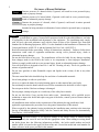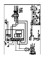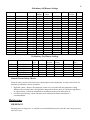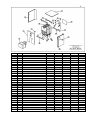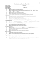
1
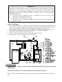
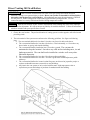
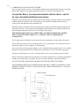
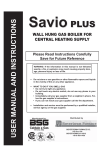
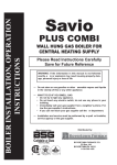
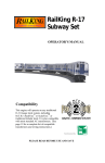
INSTALLATION AND OPERATOR’S MANUAL SL375 THRU SL7175 CAST IRON BOILERS Keep these instructions with the boiler at all times for future reference BOYERTOWN FURNACE CO. PO Box 100 BOYERTOWN, PA 19512 1-610-369-1450 www.boyertownfurnace.com 9-1-13 2 Be Aware of Hazard Definitions Danger Denotes presence of a hazard which, if ignored, will result in severe personal injury, death or property damage Warning Denotes presence of a hazard which, if ignored could result in severe personal injury, death or substantial property damage. Caution Denotes the presence of a hazard, which if ignored, could result in minor personal injury or property damage Notice Intended to bring attention to information, but not related to personal injury or property damage. Danger This equipment must be installed, adjusted, serviced and started only by a qualified service agency – an individual or agency, licensed and experienced with all codes and ordinances, and who is responsible for the installation and adjustment of the equipment. The installation must comply with all local codes and ordinances and with the latest revision of the National Fire Protection Standard for Oil Burning Equipment, NFPA 31 or the Standard for the Installation of Domestic Gas Conversion Burners, ANSI Z21.8, and the National Fuel Gas Code, ANSI Z223.1, Read all instructions before proceeding. Follow all instructions completely. Failure to follow these instructions Warning could result in equipment malfunction causing severe personal injury, death or substantial property damage. Do not alter this boiler in any way. The manufacturer will not be liable for any damage resulting from changes made in the field to the boiler or its components or from improper installation. Failure to comply could result in severe personal injury, death, or substantial property damage. Your oil fired boiler is designed to burn No. 1 and No. 2 heating oil only. Never use gasoline or a mixture of gasoline and oil. Do not store gasoline or other flammable vapors and liquids in the vicinity of this or any other appliance. The area around the boiler should be kept free and clear of combustible materials. Never burn garbage or refuse in your boiler. Never try to ignite the burner by tossing burning papers or other material into your boiler. Do not attempt to start the burner when excess oil has accumulated or the boiler is full of vapors. Do not operate boiler if the heat exchanger is damaged. Do not jumper, attempt to bypass or override any of the safety limit controls. Do not use this boiler if any part has been under water. Immediately call a qualified service technician to inspect the boiler and replace any part of the boiler, control system or burner that has been under water. All installations must conform to the requirements of the authority having jurisdiction. Such applicable requirements take precedence over the general instructions of this manual. Where required by the authority having jurisdiction, the installation must conform to the American Society of Mechanical Engineers Safety Code for Controls and Safety Devices for Automatically Fired Boilers, ANSI/ASME CSD-1. NOTICE Concealed Damage- If you discover damage to the burner, boiler or controls during unpacking, notify the carrier at once and file the appropriate claim. When calling or writing about the boiler please have the following information available: the boiler model number and serial number which is located on the upper left front of the unit. Record the model and serial number for future reference in the space provided in this manual. 3 Table of Contents Ratings and Data………………………………………………………………………4 Clearances……………………………………………………………………..............5 Ventilation and Combustion Air………………………………………………………5 Boiler Assembly……………………………………………………………….............6 Temperature control Installation and Adjustment Boiler Trim Piping System Piping………………………………………………………………...……….7 Bypass Piping Low Water Cut-Off Relief Valves Expansion Tanks Venting Systems……………………………………………………………………....8 Chimney Venting Direct Venting Burner Installation……………………………………………………………….…...13 Oil Tank and Piping……………………………………………………………….….13 . Gas Piping………………………………………………………………………….…14 Wiring…………………………………………………………………………..……..14 Swing Door……………………………………………………………………..……..17 Opening the Door Closing the Door Door Hinge Reversal Operation………………………………………………………………………..……..17 Sequence of Operation Start Up Start Up Equipment Burner Adjustments Control Circuit Safety Checks Maintenance……………………………………………………………………..…….19 Boiler Burner Vent System Domestic Water Tank……………………………………………………………..…..20 .. Parts Diagrams…………………………………………………………………..…….21 Warranty …………………………………………………………………………..….22 Installation and Service Check List …………………………………………………..23 4 Ratings and Data Boiler Model No. Firing Rate - #2 Fuel Oil Input BTU/HR DOE Capacity BTU/HR Net IBR Rating BTU/HR Net Rating Sq. Ft. AFUE Rating Water Capacity Gallons Cabinet Height Cabinet Width Cabinet Length Supply Outlet Height Return Outlet Height Flue Outlet Diameter Flue Outlet Height. Approx. Shipping Weight SL375 0.75 105,000 91,000 79,000 526 85.0 3.6 28 7/8" 17 3/4" 19 1/4" 25 3/8" 4 1/2" 6" 20 3/4" 300 SLD375 0.75 105,000 91,000 79,000 526 85.0 3.6 28 7/8" 17 3/4" 19 1/4" 25 3/8" 4 1/2" 6" 20 3/4" 300 SL4100 1.00 140,000 122,000 106,000 707 86.1 4.3 28 7/8" 17 3/4" 22 3/4" 25 3/8" 4 1/2" 6" 20 3/4" 350 Boiler Model No. Gas Input BTU/HR DOE Capacity BTU/HR Net IBR Rating BTU/HR Net Rating Sq. Ft. AFUE Rating Water Capacity Gallons Cabinet Height Cabinet Width Cabinet Length Supply Outlet Height Return Outlet Height Flue Outlet Diameter Flue Outlet Height. Approx. Shipping Weight SLD4100 1.00 140,000 122,000 106,000 707 86.1 4.3 28 7/8" 17 3/4" 22 3/4" 25 3/8" 4 1/2" 6" 20 3/4" 350 SL375G 90,000 76,000 66,000 440 85.0 3.6 28 7/8" 17 3/4" 19 1/4" 25 3/8" 4 1/2" 6" 20 3/4" 300 SL5125 1.25 175,000 153,000 133,000 887 86.5 5.1 28 7/8" 17 3/4" 26 1/4" 25 3/8" 4 1/2" 6" 20 3/4" 390 SL4100G 115,000 98,000 85,000 567 85.1 4.3 28 7/8" 17 3/4" 22 3/4" 25 3/8" 4 1/2" 6" 20 3/4" 350 SLD5125 1.25 175,000 153,000 133,000 887 86.5 5.1 28 7/8" 17 3/4" 26 1/4" 25 3/8" 4 1/2" 6" 20 3/4" 390 SL5125G 150,000 127,000 110,000 733 85.1 5.1 28 7/8" 17 3/4" 26 1/4" 25 3/8" 4 1/2" 6" 20 3/4" 390 SL6150 1.50 210,000 184,000 160,000 1,067 86.4 5.8 28 7/8" 17 3/4" 29 3/4" 25 3/8" 4 1/2" 6" 20 3/4" 430 SL7175 1.75 245,000 208,250 181,100 1,207 85.0 6.5 28 7/8" 17 3/4" 33 1/4" 25 3/8" 4 1/2" 6" 20 3/4" 470 5 Installation Clearances WARNING Boilers in rooms shall be installed with the clearances from combustible materials not less than indicated below. Combustible materials are those made of or surfaced with wood, compressed paper, plant fibers, plastics, or other material that will ignite and burn, whether flame proofed or not, or whether plastered or not. The boiler must not be installed on combustible flooring. The boiler is approved for installation on non combustible flooring only. The boiler must not be installed on carpeting or vinyl flooring Minimum clearances to combustible construction are as follows: TOP - 6 IN. FRONT - 12 IN. FLUE CONNECTOR SINGLE WALL VENT PIPING - 9 IN. FLUE CONNECTOR DOUBLE WALL INSULATED DIRECT VENT PIPING – 2” REAR - 2 IN. SIDES - 2 IN. Consult NFPA-31 for construction techniques where the above minimum clearances cannot be obtained Minimum recommended clearances for service and access are as follows: TOP - 24 IN. FRONT - 24 IN. FROM BUNER FLUE CONNECTOR - 9 IN. REAR - 18 IN. SIDES - 12 IN. Note: When installed in a utility room, the door should be wide enough to allow the largest boiler part to enter, or to permit replacement of another appliance such as a water heater. Ventilation and Combustion Air Warning…Air openings to combustion area MUST NOT BE OBSTRUCTED. Adequate combustion air must be supplied at all times. Ventilation of boiler room must be adequate enough to provide sufficient air for combustion. When a boiler is located in an unconfined space in a building of conventional frame or masonry construction infiltration may provide adequate air for combustion and ventilation. If there is any doubt, install air supply provisions for combustion and ventilation in accordance with section 5.3, Air for Combustion and Ventilation, of the NFPA54 code, it is recommend that you follow, the applicable provisions of the local building codes as well. When a boiler is installed in a confined space, in a building of unusually tight construction, air for combustion and room ventilation must be obtained from the outdoors or from spaces freely communicating with the outdoors. A permanent opening or openings having a total free area of not less than 1 square inch per 5,000 BTU per hour of total input rating of all appliances shall be provided. Ducts may be used to convey make-up air from the outdoors and shall have the same cross-sectional area of openings to which they are connected. When air for combustion and room ventilation is from inside buildings, the confined space shall be provide with two permanent openings, one starting 12 inches from the top and one 12 inches from the bottom of the enclosed space. Each opening shall have a minimum free area of 1 square inch per one thousand (1,000) BTU per hour of the total input rating of all appliances in the enclosed space, but must not be less than one 6 hundred (100) square inches. These openings must freely communicate with the interior areas having adequate infiltration from the outside. When the boiler is installed in a confined space and all air is provided from the outdoors, the confined space shall be provided with two permanent openings. One commencing within 12 inches from the top, and one commencing 12 inches from the bottom of the enclosure. The openings shall communicate directly, or by ducts, with the outdoors or spaces (crawl or attic) that freely communicate with the outdoors. One of the following methods must be used to provide adequate air for ventilation and combustion. 1. When directly communicating with the outdoors, each opening shall have a minimum free area of 1 square inch per 4,000 BTU per hour of total input rating of all equipment in the enclosure. 2. When communicating with the outdoors by means of vertical ducts, each opening shall have a minimum free area 1 square inch per 4,000 BTU per hour of total input rating of all appliances in the enclosed space. 3. If horizontal ducts are used, each opening shall have a minimum free area 1 square inch per 2,000 BTU per hour total input rating of all appliances in the enclosed space. 4. When ducts are used, they shall be on the same cross sectional are as the free area of the openings to which they connect. The minimum dimensions of rectangular air ducts shall not be less than 3 inches. In calculating free area using louvers, grills or screens for the above, consideration shall be given to their blocking effect. Screens used shall not be smaller than ¼ inch mesh. If free area through a design of louver of grill is known, it should be used in calculating the size opening required to provide the free area specified. If the design and free area is knot known, it may be assumed that wood louvers will have 20-25% free area and metal louvers and grills will have 60-75% free area. Louvers and grills shall be fixed in the open position or interlocked with the boiler so that they are opened automatically during boiler operation. Boiler Assembly LOCATE BOILER…in front of final position before removing crate. PROVIDE A LEVEL SOLID BASE as near chimney or direct vent as possible and centrally located with respect to the heat distribution system as practical. The boiler must be placed within distances from boiler room walls and ceilings that comply with existing building codes and for ease of service. THE PACKAGED BOILER IS SHIPPED IN TWO PACKAGES. a. Boiler and Cabinet Assembled and Crated b. Burner/Parts Box – Includes burner, aquastat and trim piping LOCATE THE BOILER in the position to be assembled and piped. Remove crate, plastic protective wrapper and INSPECT FOR DAMAGE. All equipment is carefully manufactured, inspected and packaged by experienced workers. Our responsibility ceases upon delivery of the crated boiler to the carrier in good condition. ANY CLAIMS FOR DAMAGE OR SHORTAGE IN SHIPMENT MUST BE FILED IMMEDIATELY against the carrier by the consignee. Temperature Controls Installation and Adjustment 1. Install the temperature control on the right side of the boiler. Attach the Honeywell L7248C aquastat or the Hydrostat 3250 to the jacket side panel using sheet metal screws and the holes provided in the jacket panel. The sensor wires should be run through the bottom knockout in the aquastat. The rubber grommet provided with the sensor wires is to be securely inserted into the aquastat knockout. 2. Connect the sensor leads to the appropriate temperature control terminals. 3. Connect your line voltage and thermostat wires if applicable to the control. See electrical diagrams for proper connections. 4. The overall range of the High Limit is from 1300F to 2200F. Typically it would be set in the range of 1800F to 2000F. 7 IMPORTANT In accordance with Section 325 (f) (3) of the Energy Policy and Conservation Act, this boiler may be equipped with a feature that saves energy by reducing the boiler water temperature as the heating load decreases. This feature may be equipped with an override which is provided primarily to permit the use of an external energy management system that serves the same function. THIS OVERRIDE MUST NOT BE USED UNLESS AT LEAST ONE OF THE FOLLOWING CONDITIONS IS TRUE: An external energy management system is installed that reduces the boiler water temperature as the heating load decreases. This boiler is not used for any space heating. This boiler is part of a modular or multiple boiler system having a total input of 300,000 BTU/Hr or greater. Boiler Trim Piping 1. Knocked down- Install the ¾” temperature control immersion well in upper right side tapping of the rear boiler section. Install the temperature sensor all the way into the well until it hits bottom and fasten in place with the retaining nut (Honeywell) or retaining grommet (HydroLevel) as provided. 2. Pipe in pressure relief valve with ¾” elbow and with the ¾” x 3” nipple in upper left side of the rear section. Relief valve discharge must be piped vertical and to a safe place of discharge. 3. Pipe in boiler drain in the lower left side rear section. 4. Install a ¾” pipe plug in the lower portion of the front section if required. 5. Knocked down – Pipe in boiler gauge in upper front section. System Piping Important… INSTALLATION MUST BE PERFORMED BY TECHNICALLY QUALIFIED SERVICEMEN SOLAIA BOILERS HAVE A MAXIMUM OPERATING PRESSURE OF 58PSI NOTE: If normal operating pressures are greater than 30psi please contact the manufacturer for required trim. 8 Pipes that are connected to boiler fittings must be supported and placed so that they do not create stresses on the boiler fittings themselves. BY PASS PIPING IS REQUIRED ON ALL LOW MASS BOILERS WHERE THE BOILER RETURN WATER TEMPERATURE COULD OPERATE BELOW 130ºF FOR EXTENDED PERIODS OF TIME. The Solaia boiler is a highly efficient low mass boiler in which care must be taken to ensure that high volumes of low temperature water are not introduced into the boiler. Operating at return water temperatures below 130ºF for extended periods of time will allow for the accumulation of condensation, scale and increased soot formation in the boiler. Corrosion and eventual heat exchanger failure will result. A thermostatic bypass valve is highly recommended on high water volume standing cast iron systems. A thermostatic bypass valve will consistently ensure that return temperatures to the boiler exceed 130oF at all times. See Figure 1 for Thermostatic Bypass valve piping. Instead of using a thermostatic bypass, bypass piping may be accomplished by placing a 3/4” bypass line with a throttling valve for regulation between the supply piping and return piping. Boiler return water temperatures must exceed 130ºF with the bypass properly adjusted. Low water cut off Hot water boilers installed above radiation level must be provided with a low water cut off device at time of the boiler installation. Relief Valves Relief valves are to be properly piped in to conform to code standards. Discharge piping from the relief valve must be piped to a drain or must terminate 6” above the floor to eliminate damage to the structure or personal injury. It must not be piped to a point where freezing may occur. Expansion Tanks The expansion tank must be properly sized to the system requirements. An undersized expansion tank will cause system water to be lost through the relief valve and make up water to be introduced through the fill valve. Continual introduction of fresh water will cause boiler failure. VENTING WARNING Failure to follow all instructions can result in flue gas spillage and carbon monoxide emissions, causing severe personal injury or death. All chimneys must meet the requirements of NFPA 211 and NFPA 31 or NFPA 54 Chimney The boiler must be connected to an adequate chimney or an approved venting system in accordance with these instructions. An adequate chimney or venting system is one that is sealed and lined with the capability of producing a -.04" W.C. flue draft and having the capacity to handle the amount of flue gas that is introduced. Masonry and metal chimneys shall be constructed in accordance with applicable building code requirements. Masonry chimneys shall be lined with an approved clay tile liner or a listed chimney lining system installed in accordance with manufacturers’ instructions and also meeting the requirements of NFPA-211 Standard for Chimneys, Fireplaces, Vents, and Solid Fuel-Burning Appliances. Metal chimneys also shall meet the requirements of NFPA-211. Factory built chimneys shall be listed and shall be installed in accordance with their listing and NFPA-211. 9 Prior to installation of the boiler, the chimney or venting system shall be examined by the installer and determined to be in good condition. All joints of the chimney must be tightly sealed. The inside of the chimney should be free of all obstruction, such as loose brick, broken pieces of tile, or corroded metal. If chimney flues are divided or there are multiple flues within one chimney, make sure there are no openings in the partition separating the divided or individual flues. When a new appliance is connected to an existing chimney, that chimney shall be brought up to current requirements. Chimneys which are relined shall be done so with an approved liner that will resist corrosion, softening, or cracking from the flue gasses. All chimney clean-out doors and flue connections must fit tightly so they will seal to avoid air infiltration. The inside area of the chimney liner should equal, at a minimum, the area of the vent pipe exiting the furnace. If more than one appliance is installed, the area of both appliances shall be used in determining the required inside area of the chimney. The flue gas exit of a chimney shall be at least 3 feet above the highest point where it passes through the roof of a building and at least 2 feet higher than any portion of a building within 10 feet of such chimney. The chimney height will also be determined by the height of the surrounding trees, buildings and terrain. When chimney downdraft conditions cause faulty operation that creates a hazard, corrective steps must be taken. When altering the surrounding obstructions is not possible, a chimney cap can be constructed on the top of the chimney to avoid downdrafts. The chimney cap should be pyramid shaped on the top with a perfectly flat surface immediately above the chimney outlet. The hood should be attached by four (4) iron supports. The four iron supports should be equal in height to the width of the chimney opening. Four plates, flaring down, can be added to help insure that the wind will pass straight over the chimney outlet. Chimney Relining A tile lined masonry chimney serving the boiler should comply with applicable building codes such as NFPA-211. An additional listed lining may be required to reduce transient low draft during startup and acid water condensation during cyclic operation. This is particularly true for high mass masonry chimneys serving furnaces of higher efficiency. For masonry chimneys, local experience can indicate how well construction has withstood the lower temperatures produced by higher efficiency furnaces. Evidence of potential or existing chimney damage should be determined by visual inspection of the chimney and liner. Exterior indicators such as missing or loose mortar/bricks, white deposits on the brick or water stains on the interior building walls should be investigated further. The operational flue temperatures for boilers range from 350ºF to 450ºF at the outlet of the boiler. These temperatures are further reduced before reaching the chimney due to heat loss through the vent connector and dilution from the draft regulator. The resulting flue gas temperatures may become low enough to form condensation on the chimney liner walls. To prevent condensation, it is necessary that the internal chimney wall temperature always be kept above the dew point of the flue gasses. If the chimney is a masonry type, it may have to be lined with a flue liner, if the temperature loss is too great for the boiler. A liner will act as an insulator and reduce the flue gas temperature loss. Insulation may be added around the liner for further temperature stability. Chimney Connector The chimney connector pipe between the boiler and chimney shall be of equal diameter as the flue outlet of the boiler. Refer to boiler specifications in this manual for proper size flue pipe for your model boiler. Any reduction in size required for the chimney must be made at the chimney connector. The vent connector pipe must be made of 24 gauge (or thicker) corrosion-resistant steel. The vent connector pipe should be as short as possible and installed so that it has a continuous rise from the boiler to the chimney. Long horizontal vent runs can result in the possibility of condensation in the flue pipe or the chimney. All horizontal runs of vent connector pipe should be pitched upward a minimum of 1/4 inch per foot of run. The horizontal length of 10 the vent pipe connector shall not exceed 10 feet. The chimney connector shall be installed so as to minimize the number of elbows and to avoid sharp turns or other construction features that would create excessive resistance to the flow of flue gasses. Tees may be used in a straight section in conjunction with a barometric draft regulator; however, they must not be used for a 90° turn. No device that will obstruct the free flow of flue gasses shall be installed in the chimney connector. This does not exclude the use of devices specifically designed for the use in chimney connectors such as automatic dampers. The vent pipe should be joined with metal screws and supported by straps. A thimble should be used to connect the vent connector pipe to the chimney so the pipe may be readily removed in case of inspection or replacement. No chimney connector shall pass through any floor or ceiling. The vent connector pipe must not pass through a combustible wall or partition unless they are guarded at the point of passage by a ventilated metal thimble not less than 12 inches larger in diameter than the connector, on metal or fireclay thimbles adequate protection is provided at the passageway. An acceptable passageway could be either an approved, ventilated metal thimble which is at least 12 inches larger in diameter than the vent connector pipe, or brick work which is at least 8 inches thick constructed into the wall and surrounding the vent connector Clearances from combustible materials or materials shall be in accordance with the clearances given. The vent connector pipe should extend only to (and not beyond) the inside wall of the chimney. A thimble should be used to connect the vent connector pipe to the chimney so that the vent connector pipe may be readily removed in case of inspection or replacement. Connection to the chimney must be made above the bottom of the chimney to avoid blockage. Vent piping should extend just into the chimney far enough to expel flue gasses. Inserting the vent piping too far into the chimney will cause undue obstruction. Use a thimble or a slip joint where vent pipe enters the chimney to allow easy removal for cleaning. If a draft regulator is required in the vent piping; it should be located at least 24 inches from the boiler if possible in either a horizontal or vertical section of the vent pipe. The draft regulator must be installed in the same room as the boiler and in such a manner that there is no difference in pressure between the air in the vicinity to the regulator and the combustion air supply. Ensure that the barometric damper is accessible for adjustment. A Field controls type MG-1 double acting draft control and a GSK-3 thermal safety spill switch are provided and must be installed with the gas burner. Refer to the manufacturers installation and operation instructions for proper installation. With the burner operating, use a draft gauge to adjust the regulator to the proper setting (see instructions enclosed with draft gauge to adjust the regulator to the proper setting). When the burner air supply and draft are properly adjusted, the draft in the flue should be a negative .02" W.C. to negative .04” W.C. Two or more appliances each equipped with a safety control may be permitted to be connected to one common chimney if sufficient draft is available for the safe simultaneous removal of all products of combustion. If two or more openings are provided into one chimney, they shall be at different levels on the same story of the building, with the smaller appliance entering at the highest possible level consistent with clearances to combustible materials. Two or more connectors shall not be joined together unless the common connector, manifold and chimney are properly sized. Adequate draft must be available to safely remove all products of combustion simultaneously without leakage, or back flow. 11 Direct Venting Oil Fired Boilers WARNING Failure to follow all instructions can result in flue gas spillage and carbon monoxide emissions, causing severe personal injury or death. Direct vent systems are intended for oil fired boilers only and are not designed for gas fired boilers. All installations must meet the requirements of NFPA31. Use only the ETL listed venting system components supplied with the packaged boiler. All vent connections must be securely fastened and sealed with high temperature sealant. Caution External vent surfaces are hot. Surface discoloration of the building may occur due to improper burner or boiler adjustment. We will not accept any liability for such discoloration. Follow all instructions which are included with your specific direct vent kit. 1. Choose the vent location. The preferred location of venting system is on the opposite wall of the known prevailing winds. 2. The exit terminal of the system must conform to the following guidelines. See figure on following page. a. The vent terminal shall not be less than 3 feet above any forced air inlet to the house. b. The vent terminal shall not be less than 4 feet below, 4 feet horizontally, or 1 foot above any door window or gravity inlet into the building. c. The vent terminal shall be installed at least 1 foot above ground. The vent must be maintained to keep the location 1 foot above any solid surface including snow, ice and landscape materials. The vent shall not be installed in a window well or any other fabricated depression. d. The vent terminal shall not be less than 2 feet from an adjacent building. e. The vent terminal shall not be less than 7 feet above grade when located adjacent to public walkways. f. The vent terminal shall not be located so that flue gasses are directed to jeopardize people or overheat combustible structures, materials or enter buildings. g. All joints in the vent system are to be sealed with Permatex high temperature sealer or equivalent to prevent the leakage of products of combustion into the building 12 3. COMBINATION AIR INTAKE/VENT SYSTEM The vent system consists of 10 or 15 foot lengths of double wall insulated flexible stainless vent piping and an equal length of 4” air intake piping and a stainless steel intake/vent termination end. Consult the Direct Vent manual included with the direct vent kit for more detailed installation instructions. Install the vent termination thru the opening in the wall centering it in opening. Apply a bead of silicone caulking around the perimeter of the vent termination end. Attach the termination to the house by screwing it fast thru the holes in the termination end. Install the flexible vent piping with the provided connector between the boiler and the termination end. The joints at the boiler, vent connectors, and termination end should be securely fastened and must be sealed with high temperature silicone to prevent leakage of flue gasses. THE MINIMUM DISTANCE TO COMBUSTIBLE MATERIALS FROM THE DOUBLE WALL INSULATED VENT PIPING IS 2”. CONSULT NFPA-31 FOR REDUCED CLEARANCES. The air intake must be installed to the air inlet collar on the combination vent hood and to the burner. The air intake kit consists of one 4” galvanized elbow, one 4” galvanized tee, one vacuum relief valve (barometric damper), and one length of 4” flexible piping. The vacuum relief valve (barometric damper) is to be assembled and then installed in the 4” tee with the hardware provided. Install the fresh air intake duct tee and damper as close as possible to the burner. The purpose of the damper is to act as a vacuum breaker in the event of a blockage in the air intake. NOTE: The balance weight of the vacuum relief valve must be installed in a level position and adjusted to lightly close while burner is operating. Be sure to lock the balancing weight after adjustment. ALL JOINTS IN THE AIR INTAKE ASSEMBLY MUST BE SECURELY FASTENED. THE MAXIMUM LENGTH OF FLEXIBLE AIR INTAKE DUCT, WHICH CAN BE RUN TO THE BURNER, IS TWENTY FEET PLUS THE LENGTH THAT RESULTS FROM THE 4” TEE AND 4” ELBOW SUPPLIED. 13 DIRECT VENT OIL BURNERS Riello Burners All Riello direct vent burners are shipped with the nozzle for the SLD375 installed. A separate nozzle is included in the burner carton for the SLD4100 and SLD5125. See the burner set up page or the Installer Serviceman Label attached to the boiler for the appropriate burner settings. Boilers supplied with Riello burners will also be supplied with a 3” to 4” galvanized adapter. The adapter is to be fastened directly to the flange opening on the burner cover using three sheet metal screws. The Riello BF5 burners for use with direct vent systems are shipped with the controls, which provide pre and post purge. Pre purge is provided to ensure clean starts under all conditions. Post purge is provided to ensure that the boiler fires at maximum efficiency and dependability throughout the heating season. Post purge timing is variable. The factory set post purge timing should be set at approximately 45 seconds. Post purge times in excess of 60 seconds when using the Riello burner will cause the Honeywell Aquastat to lock out on an error code Err4 B1 fault. Burner Installation The burner is mounted to the door with (4) 8mm studs, nuts and washers (located in the burner trim bag). Thread the (4) studs in to the (4) M8 holes threaded to permit connection to the burner. Thread the shorter length of stud into cast door. Check that the correct nozzle is properly installed in the burner as shown in the preliminary burner settings and that the burner electrodes are adjusted as per the burner manual. When using the Beckett AFG, Carlin EZ-1,Carlin EZ gas or the Beckett CF375 , the opening in the refractory on the door must be enlarged to insert the burner without damaging the door refractory. Use a sharp utility knife to carefully trim the opening to size. The oil burner when properly installed will extend beyond the refractory liner of the burner door. Riello - will extend approximately 2” beyond the refractory on the swing door. Beckett AFG - will extend approximately 4-1/8” beyond the refractory on the swing door. Beckett NX - will extend approximately 2-3/4” beyond the refractory on the swing door. Beckett CF 375 – will extend approximately 1/2” beyond the refractory on the swing door. Check that there is a complete seal between the door and the burner flange after installing ceramic fiber seal furnished with the burner. Oil Tank and Piping Oil tanks and piping should be installed in accordance with the National Board of Fire Underwriters and local codes. Connection of the oil line to burner must be positioned to permit easy opening of the burner swing door. Use continuous heavy walled copper tubing with flare fittings only. Do not use compression fittings. Do not run overhead fuel lines from tank to oil burner. Fuel pump supply and return connections should be made according to instructions attached to the fuel pump. An oil line filter and shut-off valve should be installed in the suction line. 14 On a two- pipe system you will need to supply a second approved flexible oil line in order to be able to swing the burner door open without disconnecting oil lines. An optional flexible oil line is available through your distributor. Gas Piping Connect from the gas supply to the burner combination gas valve inlet using new, approved gas lines and fittings only. Provide support for gas piping. Do not rest weight of piping on burner gas valve. Apply pipe dope sparingly at all joints. Use only pipe dope listed for use with natural or propane gas. Do not use pipe sealing tape. Do not hold gas valve with pipe wrench. Use crescent wrench or other smooth-jawed device. Do not over-tighten. Failure to comply with above could result in severe personal injury, death or substantial property damage. Warning 1 Pipe Capacity Table - Natural Gas BTU/Hr Equivalent Pipe Nominal Pipe Diameter Inches Length2 3/4” 1” 1-1/4” 15’ 172,000 345,000 750,000 30’ 120,000 241,000 535,000 45’ 99,000 199,000 435,000 60’ 86,000 173,000 380,000 75 77,000 155,000 345,000 90’ 70,000 141,000 310,000 105’ 65,000 131,000 285,000 120’ 120,000 270,000 150’ 109,000 242,000 180’ 100,000 255,000 Note: 1. Using 0.06 Specific Gravity Gas and a pressure drop of 0.3” of Water Column 2. To obtain equivalent length of pipe add total length of pipe plus 3’ for each 90o elbow Electrical Wiring ELECTRICAL WIRING MUST CONFORM TO THE NATIONAL ELECTRICAL CODE, ANSI/NFPA No. 70-1990 AND LOCAL CODES. THE BOILER MUST BE ELECTRICALLY GROUNDED AND ON A SEPARATE FUSSED DISCONNECT SWITCH. ELECTRICAL SHOCK IS HAZARDOUS. TURN OFF ALL POWER SUPPLIES AT SERVICE ENTRANCE BEFORE STARTING TO MAKE WIRING CONNECTIONS OR REPAIRS. Refer to wiring diagrams in rear of manual for electrical connections. The boiler should be connected by a separate, permanently live electrical supply line with a 15 amp fused rating. Use No. 14 AWG wires rated for at least 90o C. Install a separate fused disconnect switch near the boiler so power can be shut off for servicing. Caution: Label all wires prior to disconnection when servicing controls. Wiring errors can cause improper and dangerous operation. Verify proper operation after servicing. Install the room thermostat on an inside wall away from fireplaces, appliances or sunlight. Set the heat anticipator according to the instructions from the aquastat manufacturer. Connect the thermostat leads to the “TT” connections on the aquastat control or system control. 15 16 17 Swing Door Opening the Door 1. 2. 3. 4. 5. 6. Turn off power to boiler. Allow boiler to cool down. Unplug the burner power cable at factory-supplied burner Molex plug electrical disconnect. Lift the front jacket panel up and off the boiler. Remove the four nuts from swing door studs. Swing open burner door to the left while gently lifting to prevent rubbing of door studs. Closing the Door 1. Swing burner door to right while lifting at the burner to prevent the door from rubbing on the lower (2) 8mm studs until the insulation is slightly compressed and the studs are exposed. 2. Install the nuts onto the upper studs. 3. Attach nuts to the lower studs and hand tightening only. 4. Tighten the upper nuts first followed by the lower nuts until a complete seal is made. Door Hinge Reversal WARNING: IN ORDER TO MOVE THE DOOR HINGES SAFELY TO THE RIGHT SIDE YOU MUST MOVE THE TEMPERATURE CONTROL TO THE LEFT SIDE CABINET PANEL. THIS IS TO INSURE POWER IS SAFELY REMOVED FROM THE BURNER WHEN OPENING THE BURNER SWING DOOR. FAILURE TO DO SO MAY RESULT IN PROPERTY DAMAGE OR SERIOUS INJURY. 1. The knock out on the upper left side panel of the cabinet must be removed and a snap plug will have to be installed to close up the hole for normal aquastat position on the right side jacket panel. 2. Install the box connector into the left side jacket panel. 3. The plastic anti short bushings in the upper brackets must be removed from the holes in the right side and placed in the holes on the left side of the upper brackets. 4. The ¾” aquastat immersion well must be moved to the upper left rear ¾” tapping and the relief valve must be installed in the upper right rear ¾” boiler tapping. 5. The 48” sensor wires must be run through the upper left side brackets and through the ½” electrical fitting in the left side panel. 6. Install the temperature control on the boiler left side jacket panel. 7. Remove the hinges from the left side of the boiler. 8. Remove the 8mm stud from the left lower position and install in the right lower position. 9. Reinstall the hinge brackets using the 8mm bolt for upper hinge and nut and washer on lower hinge. 10. Riello Burner - Remove the burner Molex wiring harness from the right side of the burner and install on the left side of the burner. Beckett Burner – Remove the Molex wiring harness from its existing position in the burner junction box and place it in the knock out marked number 2. Operation Sequence of Operation If the room temperature or indirect water heater falls below the thermostat setting a call for heat will start the burner and circulating pump. The burner and pump will continue to operate until the room heating or domestic water requirements are met. In the event the boiler water temperature reaches the High Limit setting the burner will shut off with the circulator continuing to operate. If the thermostat continues to call for heat and the boiler temperature falls below the High Limit setting the burner will restart. 18 Start-Up Warning…Use only … No. 2 fuel oils. Note: Note: Do not attempt to start the burner if excess oil has accumulated. Do not use gasoline, crankcase draining or any oil containing gasoline. 1. 2. 3. 4. Make sure that normal water level has been obtained in the boiler and system. Check that all safety devices are in place. Check that thermostats are correctly connected and set. Check that the inside of the boiler is free of any fuel residue or foreign materials and that the ceramic fiber insulation on the burner door has not been damaged. 5. Check oil burner nozzle to ensure that the right size and type is installed and tight in the adapter. See preliminary settings for proper nozzle size and type. 6. Check electrode settings, as they may have been jarred out of position during transportation. See burner instructions for nozzle and electrode setting 7. Check that the Burner mounting bolts are tight. 8. Lubricate burner motor and circulator motor if required. 9. Open all fuel valves. 10. Set room thermostat to call for heat. 11. Set aquastat high limit between 180oF and 200oF 12. Turn service switch on. Burner should start. On one pipe fuel system only you may have to bleed the oil system. To bleed attach a clear plastic tube to the oil pump bleed port and allow oil to run until all the air is out of the oil suction line feeding the oil burner. See burner and fuel pump manufacturers recommendations for proper bleeding of the fuel system. 13. Turn “OFF” burner and install pressure gauge into the gauge port on the pump. See the burner manufacture’s manual for location of ports. 14. Start burner again and check oil pressure for conformance to preliminary oil burner settings. Adjust if necessary. See oil burner manufacturer’s instructions for pump adjustment. Start-up Equipment THE FOLLOWING PROPER COMBUSTION INSTRUMENTS ARE REQUIRED TO DETERMINE PROPER AIR ADJUSTMENTS AND DRAFT WHEN SETTING UP OR SERVICING THE BURNER. 1. 2. 3. 4. 5. 6. 7. CO2 Analyzer CO Analyzer Draft gauge Fuel pressure gauge Stack thermometer Smoke tester Manometer Do not attempt to make any adjustments or start the boiler without the proper equipment. Burner Adjustments Consult the enclosed burner manufacturer’s installation and operation manual for proper adjustment of the burner. 19 Preliminary Oil Burner Settings Boiler Burner Nozzle SL375 Riello F3 Riello F5 Beckett AFG Beckett NX Carlin EZ-1 Riello BF5 Riello F5 Beckett AFG Beckett NX Carlin EZ-1 Riello BF5 Riello F5 Carlin EZ-1 Beckett NX Riello BF5 Riello F5 Beckett NX Riello F10 Beckett CF375 .55x60oA .50x60oA .60x70oB .60x60oB .60x60oW .50x60oA .65x60oA .75x60oB .85x60oB .85x45oB .65x60oA .85x60oA 1.00x60oB 1.00x60oB .85x60oA 1.00x60oA 1.25x45oB 1.35x60oW 1.35x45oB SLD375 SL4100 SLD4100 SL5125 SLD5125 SL6150 SL7175 Air Setting 2.50 2.50 6/0 N/A 0.55 3.25 3.25 7/1 N/A 0.75 4.75 3.00 1.00 N/A 4.75 5.75 N/A 2.80 9/0 Turbulator/ Head 0.50 0.5 N/A 1.50 0.60 Bar 0.5 0.5 N/A 3.00 0.75Bar 1.0 4.0 0.75Bar 4.00 4.0 4.0 2.00 2.0 1.00 Pump Press CO2 175PSI 200 PSI 160 PSI 160 PSI 150PSI 200 PSI 200 PSI 160 PSI 140 PSI 150PSI 200 PSI 200 PSI 150 PSI 150 PSI 200 PSI 200 PSI 140 PSI 150 PSI 150 PSI 12.00% 11.0% 11.4% 11.0% 11.0% 11.0% 11.0% 11.3% 11.0% 10.5% 11.0% 11.0% 10.5% 11.0% 11.0% 11.0% 11.1% 12.0% 12.0% Draft Overfire +.02 +.02 +.02 +.02 +.02 +.05 +.04 +.04 +.04 +.04 +.08 +.07 +.07 +.07 +.11 +.09 +.09 +.11 +.11 Smoke #0 #0 #0 #0 #0 #0 #0 #0 #0 #0 #0 #0 #0 #0 #0 #0 #0 #0 #0 Preliminary Gas Burner Settings Boiler Burner SL375 SL375 SL4100 SL4100 SL5125 SL5125 Carlin EZ Gas Carlin EZ Gas Carlin EZ Gas Carlin EZ Gas Carlin EZ Gas Carlin EZ Gas Gas Type Nat LP Nat LP Nat LP Orifice 0.189” 0.154” 0.234” 0.185” 0.266” 0.209” Manifold Pressure 3.5” 3.5” 3.5” 3.5” 3.5” 3.5” Air Setting 10% 10% 20% 20% 30% 30% CO2 8.5%-9.5% 9.5%-11.0% 8.5%-9.5% 9.5%-11.0% 8.5%-9.5% 9.5%-11.0% Draft Flue -0.03” -0.03” -0.03” -0.03” -0.03” -0.03” Control Circuit Safety Checks Check the safety controls on the boiler after completing the burner adjustments. A safety control check for satisfactory performance must be performed. 1. High limit control - Remove the temperature control cover as needed and note temperature setting. With the burner running reduce the high limit setting until the burner shuts off. Return the high limit to its original setting. Consult the manufacturers installation and operation instructions for 2. Check the burner primary control and flame sensor following the burner manufacturer’s recommendations. Maintenance IMPORTANT Escaping gasses are dangerous. A qualified serviceman should inspect the entire flue and venting system at least once a year. 20 Do not use the boiler if any part has been under water. Call a qualified service technician to inspect the boiler and replace any part of the control system, which has been under water. Never operate this appliance with any safety switches altered or disabled. Never attempt to modify this appliance in any fashion. Boiler At the beginning of each heating season, the boiler flue passages and the burner should be checked for cleanliness and if necessary they should be cleaned. The following procedure is required for inspection and cleaning the boiler flue passages. 1. 2. 3. 4. 5. 6. 7. 8. 9. 10. 11. 12. Turn off all electrical power to the boiler before inspecting and cleaning. Disconnect the Molex plug at burner. Remove the boiler front jacket panel by lifting vertically. Open the swing door following previously described procedure. If required remove any scale and soot deposits with a flexible flue brush. Vacuum all deposits from flue passages and chamber area. Be careful not to damage the door insulation. Close swing door following previously described procedure. Check to ensure a proper seal between the door and the boiler has been made. Eliminate any combustion gas leaks by replacing worn seals and gaskets. Install jacket front panel. Connect Molex plug for burner power. Protect the heating system against freezing dangers with anti-freezes as required. Avoid intercommunications between domestic hot water and heating water since these antifreezes are toxic substances. Check the piping system for leaks and repair as required. This will prevent water turnover with consequent risk of scale formation and corrosion in the boiler room. Check for proper operation of the relief valve following the manufactures recommended proceedure. Corrosion can build up rapidly at the valve seat and prevent its functioning as a safety device. Burner Refer to the burner installation and operation manual provided for maintenance procedures. Vent System Chimney Vent- Inspect the chimney and vent system to ensure its cleanliness and condition. Remove any accumulation that may have occurred at the clean out door. Inspect and clean all vent piping and vent components replacing as necessary. Direct Vent – Inspect and clean vent and air intake piping. Replace and reseal joints as required. Inspect vent hood air inlet and discharge for obstruction. Domestic Hot Water Storage Tank 1. Sizing of the hot water tank must be matched with the hot water usage. 2. Piping must be in accordance with the appropriate codes and the Solaia manual. 3. Follow the installation instructions of the hot water domestic tank you have chosen to install with the Solaia boiler. Danger… Water temperature exceeding 125 F will cause severe burns instantly or death by scalding. An automatic mixing valve must be installed on the outlet of the domestic waterside of the tank. Installation must comply with the valve manufacture’s recommendations, and instructions. Pipe in accordance with the installation manual. Due to varying water conditions, an adjustable flow restrictor may be required in the coldwater inlet of the tank. 21 Item 1 1 1 1 1 1 2 3 5 6 7 8 9 9 11 12 13 14 14 15 16 17 18 19 19 20 20 21 22 23 24 Qty. 1 1 1 1 1 1 1 1 1 2 1 1 1 1 1 1 1 1 1 1 2 1 4 1 1 1 1 1 1 1 1 Description Riello F-3 Riello F-5 Oil Burner Beckett NX Oil Burner Beckett AFG Oil Burner Beckett CF375 Oil Burner Carlin EZ Gas Jacket Front Panel Temperature/Altitude Gauge Left Side Jacket Panel Jacket Upper Bracket Jacket Top Panel Nipple 3/4” x 3” Immersion Well Honeywell Immersion Well Hydrostat Drain Valve 3/4” Street Elbow 3/4” Relief Valve 3/4” Female Sensor Honeywell 48” Sensor Hydrostat 48” Jacket Rear Panel Jacket Lower Bracket Jacket Right Side Panel Spacer 1-9/16” x 1/2” Honeywell L7248 Aquastat HydroStat 3250 Wire Harness – 17” Wire Harness – 5” Pipe Plug 1/4” Brass Bushing 3/4” x 1/4” Plug 3/4” Casting Assembly SL375 541151 N/A 541160 541170 N/A 541181 508000 559560 508030 508170 508020 328003 552810 552815 327998 328002 570181 552121 552123 508010 508180 508040 594500 552129 552126C 562094 562095 712350 310410 328004 705997 SL4100 N/A 541147 541161 541171 N/A 541182 508000 559560 508060 508170 508050 328003 552810 552815 327998 328002 570181 552121 552123 508010 508180 508070 594500 552129 552126C 562094 562095 712350 310410 328004 705998 SL5215 N/A 541148 541162 N/A N/A 541182 508000 559560 508090 508170 508080 328003 552810 552815 327998 328002 570181 552121 552123 508010 508180 508100 594500 552129 552126C 562094 562095 712350 310410 328004 705999 SL6150 N/A 541149 541163 N/A N/A N/A 508000 559560 508120 508170 508110 328003 552810 552815 327998 328002 570181 552121 552123 508010 508180 508130 594500 552129 552126C 562094 562095 712350 310410 328004 705600 SL6175 N/A N/A N/A N/A 541155 N/A 508000 559560 508150 508170 508140 328003 552810 552815 327998 328002 570181 552121 552123 508010 508180 508160 594500 552129 552126C 562094 562095 712350 310410 328004 705601 22 Solaia Residential Cast Iron Boiler Warranty First Year Limited Warranty for Solaia Residential Cast Iron Water Boilers Boyertown Furnace warrants that its residential cast iron water boilers are free from defects in material and workmanship under normal usage for one year from the date of original installation. If any parts are found to be defective in manufacture during this one-year period, Boyertown Furnace Company will supply a replacement for the defective part. The Limited Lifetime warranty for the cast iron heat exchanger of its residential water boilers includes the heat exchanger only, not component parts. Boyertown Furnace Company warrants that the cast iron heat exchanger of its residential water boiler is free from defects in material and workmanship under normal usage during the lifetime of the original owner at the original place of installation. If any sections are found to have a manufacturing defect in materials or workmanship Boyertown Furnace will repair or, at its option replace them. Exceptions and Exclusions 1. The limited lifetime warranty covers only the cast iron heat exchanger assembly. The burner, jacket, controls and other equipment furnished by Boyertown Furnace Company but purchased from other manufacturers shall be limited to their warranties, if any. 2. This warranty does not cover expenses for removal or reinstallation. The homeowner will be responsible for the cost of removing and reinstalling the defective part or its replacement and all labor and material connected therewith. Replacement material will be invoiced to the distributor in the usual manner and will be subject to adjustment upon proof of defect. 3. This warranty in no way can be considered as a guarantee of workmanship of an installer connected with the installation of the Solaia cast iron or as imposing on Boyertown Furnace Company liability of any nature in the installation which liability is expressly disclaimed. 4. This warranty will not be applicable if the boiler is used or operated over its rated capacity or installed for uses other than home heating; or is not maintained in accordance with Boyertown Furnace Companies recommended or accepted good practice as determined by industry standards. 5. This warranty will not be applicable if the boiler has been damaged as a result of being improperly serviced or operated, including but not limited to the following: operated with sufficient water; allowed to freeze: subjected to flood conditions: or operated with water conditions and or fuels or additions which cause condensation, unusual deposits, or corrosion in or on the cast iron sections. 6. This warranty applies only to boilers installed in the United States. 7. In order for this warranty to be effective a) The boiler must have been installed in a single or a two family residential dwelling. This warranty doe not apply to boilers installed in apartments or commercial or industrial installations. b ) The boiler must have been assembled in strict compliance with the installation instructions furnished with the boiler. c) Boiler sections must not have been damaged in handling during shipment or installation. 8. The remedy for breach of this warranty is expressly limited to the repair or replacement of any part found to be defective under conditions of normal; and the remedy for incidental, special or consequential damages or loss such as loss of the use of the materials, inconvenience or limitation of incidental or consequential damages so the above limitations or exclusions may not apply to you. 9. The warranty is lieu of all others, and any and all express or implied warranties (including, without limitation any implied warranties of merchantability or fitness for a particular purpose), are expressly limited in duration to the period of the warranty as previously stated herein. Some state do not allow limitations on how long an implied warranty lasts so the above limitation may not apply to you. This warranty does not extend to anyone except the first purchaser at retail and only when the boiler is in the original installation Implied warranties of fitness for a particular purpose and merchantability shall be limited to the duration of the express warranty. Boyertown Furnace Company expressly disclaims and excludes any liability for consequential or incidental damages for breach of any express or implied warranty. For prompt warranty service, notify the installer who in turn will notify Boyertown Furnace distributor from where the boiler was purchased. If this action does not result in warranty service, contact the Boyertown Furnace Customer Service Department, P.O. Box 100, Boyertown, Pa. 19512, with details in support of the warranty claim. Alleged defective part or parts must be returned through trade channels in accordance with the Boyertown Furnace Company’s procedure currently in force for handling returned goods for the purpose of inspection to determine cause of failure. Boyertown Furnace will furnish the new parts to an authorized Boyertown Furnace distributor who in turn will furnish the parts to the heating contractor who installed the boiler. If you have any questions about the coverage of this warranty, contact Boyertown Furnace Company at the above address. This warranty gives you specific legal rights, and you may also have other rights which vary from state to state. 23 Installation and Service Check List Boiler Model: _______________________ Serial No.: ____________________ Installation Date: ______________________ Installer Name: ________________________ Phone No.: ____________________ Boiler Installation □ Boiler level and in solid contact with floor? □ Boiler and burner wired per wiring diagram and National Electric Code? 120VAC wiring Type_____ Size _____ AWG □ Burner sealed to boiler? Mounting nuts tight? □ Space is large enough to provide required clearances? □ Local, state and national codes, laws, regulations and ordinances followed? Vent System □ Existing chimney and vent system inspected to NFPA Code and in good condition? □ New vent pipe installed and properly sealed? □ Vent size checked against furnace manual and codes? □ Gas boilers – Double Swing Damper installed along with spill switch. Oil Burner Operation □ Burner Model: __________________ Nozzle: _______GPH _______Deg. ____Type_______ □ Burner Pump Pressure: ______________ □ Fuel filter and fuel lines installed and inspected as per burner manual? □ Air bled from oil piping? Piping checked for leaks? □ Burner started, adjusted and tested per burner manual? Gas Burner Operation □ Burner Model: ___________________ Orifice:__________ Manifold Pressure:_________ □ Fuel lines installed and inspected as per the burner manual? □ Piping checked for leaks? □ Burner started, adjusted and tested as per the burner manual? Boiler Operation □ Limit control tested for proper operation? □ Boiler observed going through several operational cycles for proper operation? Post Installation □ Reviewed owners’ information in this manual with owner or maintenance personnel and instructed to keep for future reference? □ Properly filled in and returned warranty registration card to Boyertown Furnace Co. Inserted burner manual instructions with furnace manual for future use? 24 -----------------Cut and Return This Form or register online at www.boyertownfurnace.com----------------Boyertown Furnace Co. P.O. Box 100 Boyertown, PA 19512 Boiler Model:_________________ Date Installed: _________________Serial Number: _________________ Name of Purchaser: _________________________________________________________________________ Purchaser’s Address: ________________________________________________________________________ ________________________________________________________________________ Dealer’s Name: _____________________________________________________________________________ Dealer’s Address: ___________________________________________________________________________ ___________________________________________________________________________