1
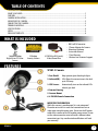
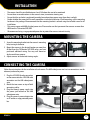
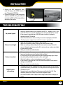
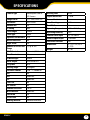
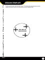
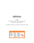
Security Camera
Indoor/Outdoor CCD Security Camera w/ Night Vision
INSTRUCTION MANUAL V1.0
www.defender-usa.com
SP301-C
IMPORTANT! PLEASE READ!
NEED
HELP?
DO NOT RETURN THIS
PRODUCT TO THE STORE
Please contact a DEFENDER® customer support representative first regarding any additional information on product
features, specifications or help with set-up.
Please contact us via one of the methods below:
Email:
[email protected]
Online live web chat:
Visit www.defender-usa.com
Telephone:
1.866.946.7828
Fax:
1.888.771.1701
For more product information visit www.defender-usa.com
Note: You may find updated versions of this manual by visiting our website
SP301-C
2
WARRANTY INFORMATION
PRODUCT WARRANTY INFORMATION
Please visit our website at www.defender-usa.com
for information about your product’s warranty.
We take quality very seriously. That is why all of our products come with a one year warranty from the original
purchase date against defects in workmanship and materials. If you have warranty or support issues please
contact us using any of the following methods:
Phone: 1.866.946.7828
Fax: 1.888.771.1701
Email: [email protected]
Website: www.defender-usa.com
DEFENDER USA
60 Industrial Parkway #Z64
Cheektowaga, NY
USA 14227 DEFENDER CANADA
4080 Montrose Road
Niagara Falls, ON
Canada L2H 1J9
Warranty Terms
1. Defender products are guaranteed for a period of one year from the date of purchase against defects in workmanship and materials. This warranty is limited to the repair, replacement or refund of the purchase price at Defender’s option.
2. This warranty becomes void if the product shows evidence of having been misused, mishandled or tam
pered with contrary to the applicable instruction manual.
3. Routine cleaning, normal cosmetic and mechanical wear and tear are not covered under the terms of this warranty.
4. The warranty expressly provided for herein is the sole warranty provided in connection with the product itself and no other warranty, expressed or implied is provided. Defender assumes no responsibilities for any other claims not specifically mentioned in this warranty.
5. This warranty does not cover shipping costs, insurance, or any other incidental charges.
6. You MUST call Defender before sending any product back for repair. You will be sent a Return Authorization number with return instructions. When returning the product for warranty service, please pack it carefully in the original box with all supplied accessories, and enclose your original receipt or copy, and a brief explanation of the problem (include RA #).
7. This warranty is valid only in Canada and the continental U.S.
8. This warranty cannot be re-issued.
CAUTION
RISK OF ELECTRIC SHOCK
TO REDUCE THE RISK OF ELECTRIC SHOCK, DO NOT REMOVE THE COVER (BACK).
NO USER SERVICEABLE PARTS INSIDE. REFER SERVICING TO QUALIFIED SERVICE PERSONNEL.
SP301-C
3
TABLE OF CONTENTS
Table of Contents
WHAT IS INCLUDED....................................................................................................................................1
FEATURES..................................................................................................................................................1
CAMERA INSTALLATION.............................................................................................................................2
Mounting the Camera.........................................................................................................................2
Connecting the camera......................................................................................................................2
trouble shooting.................................................................................................................................3
Specifications.......................................................................................................................................4
nOTES.......................................................................................................................................................5
DRILLING TEMPLATE................................................................................................................................6
WHAT IS INCLUDED
1 Indoor/Outdoor
Night Vision CCD Color
Camera
2 Window
Security Stickers
4 PIN DIN to RCA (male)
Video/Power Wire
•
•
•
•
•
•
BNC to RCA Connector
1 Power Adapter for Camera
Mounting Hardware
Instruction Manual
1 Year Warranty
Lifetime Live Customer Support
FEATURES
SP301-C Camera
1.Sun Shield: Helps prevent glare from bright lights
2.Infrared (IR): LEDs Allows the camera to see in the dark
up to 15ft away.
3. CDS Sensor: Automatically turns on the infrared LEDs
when it gets dark
4.Camera Housing
5.Camera Mount
6.4 PIN DIN Female Connection
IMPORTANT INFORMATION
While this camera is weatherproof, it is not waterproof.
Please do not install it in areas that receive direct rain or
under eaves trough draining spots. Do not cut the DC power
cable of this camera to fit with another power source. Do not
cut the video connection wire to fit with a different video
connection type. Any unauthorized modifications will void
your warranty.
SP301-C
1
INSTALLATION
•
•
•
•
•
•
The camera should be installed between 8 and 13ft above the area to be monitored
Ensure there are no obstructions in the camera’s view, to maximize viewing area
Ensure that the sunshade is positioned to avoid glare and position camera away from direct sunlight
Decide whether the camera will be wall-mounted or sit on a desk/table top. If wall mounting, use the mounting
hardware in the package. We recommend that the mounting bracket is secured using the included screws for all
installations
This camera comes with 60ft of video/power wire. Please make sure that you mount the cameras no more than
60ft from the TV/monitor/VCR/DVR
We recommend using a surge protected power bar to protect the cameras internal circuitry
Mounting the Camera
1. Screw the mounting bracket into the camera’s mounting
hole, turning it clockwise.
2. Mount the camera in the desired location no more than
60 feet from the TV/Monitor/VCR DVR unless you have
purchased additional wiring. You may wall mount or
desk mount these cameras.
3. Adjust cameras to the desired viewing angles.
Connecting the camera
Follow these instructions for the installation of each camera. The 60ft video/power wire has two connections: one for
video out, and one for power.
1. Plug the 4 PIN DIN female connection
on the camera into the 4 PIN DIN male
connection on the 60ft video/power
wire.
2. Match the two arrows on top of both
connecting cables.
3. Plug the camera’s power supply into
the power jack located on the 60ft
video/power wire.
4. Plug the camera’s power adapter into
an AC outlet or surge protected power
bar.
SP301-C
1
2
3
4
2
INSTALLATION
5. Connect the 60ft video/power wire’s
male RCA plug to the VIDEO IN port of
your TV/monitor/VCR/DVR.
6. If your VIDEO IN port is a BNC connection
(common with DVR units), you will need
to attach the BNC to RCA adapter before
connecting the camera.
5
6
troubleshooting
No picture/signal:
Picture is too bright:
Picture is too dark:
Night Vision is
not working:
SP301-C
• Make sure your TV/monitor is on the correct video input channel. This is NOT
channel 3 Common terms for this channel is INPUT, AV CHANNEL, LINE 1, LINE
2 and AUX. Please use your TV or VCR manual to correctly identify this channel
• If your camera is connected to a VCR/DVR, make sure that it is properly
connected to your TV/monitor
• Check all connections to make sure they are secure and properly connected
• Check your power supply to ensure that the camera is powered up
• Make sure your camera is not aimed at direct sunlight
• Adjust the sunshade by sliding it forwards to block out excess light
• Make sure nothing is obstructing the CDS sensor on the camera. If the CDS
sensor is blocked, night vision mode will be active and may produce extra light
in your camera’s picture
• Move your camera to another location
• If using at night, make sure your camera’s subject is no more than 15ft away
(may vary based on amount of ambient light available)
• If using during the day, your camera may not be getting enough light. Adjust
the sunshade by sliding it backwards to let in more light
• Check the brightness and contrast settings on your TV/monitor
• If your camera is connected to a VCR/DVR, check the brightness and contrast
settings on the VCR/DVR
• Move your camera to another location
• The night vision turns on automatically when light levels drop. Try the camera in
a pitch black setting. The area that it is in may have too much light and may not
activate the sensor
• Cup your hands around the front of the camera and look at the LEDs. They
should be glowing red. If they are not, check the power supply
• LEDs need to reflect off of an object within range for the camera to display an
image
3
SPECIFICATIONS
Camera Type
Weatherproof Color IR
CCD Camera
Housing Color
Black
Image Sensor
Signal/Noise Ratio
>48dB
1/4" Color SHARP CCD
Resolution
Camera Bracket
Yes
420 TV Lines
Outdoor Use
Lens Mount type
M12
Yes
IP Rating
Pan/Tilt/Zoom
No
IP65
Focal Length
Operating Temperature
-10° ~ 60°C / Degrees
3.6mm
Focus Type
Operating Humidity
98%
Fixed
Camera Power Input
DC 12V 300mA
Optimal Focal Distance 20 ft
Motion detection
Power Adapter Input
120V 60Hz
No
Night Vision
LED Power Indicator
No
Yes
Number of IR LEDs and
Range
Dimensions
12, up to 15ft
4.7"(L) x 2.5"(W) X
2.5"(H)
IR LED Control
Weight
0.7 lbs
Automatic (CDS Sensor)
Min. Illumination
0 lux
IR Wavelength
850nm
Video Output
4 PIN DIN to RCA
TV System
NTSC
Viewing Angle
60 Degrees
Electronic Shutter
1/60 ~ 1/100000 sec
BLC
No
AGC
Automatic
ELC
Automatic
Line Lock
No
Iris Control
No
Gamma Correction
>0.45
White Balance
Automatic
Sun Shield
Yes
IR Cut Filter
No
Housing Material
Anodized Aluminum
SP301-C
44
NOTES
Customer Information Card
Contact Name:
Company:
Address:
Postal Code:
Phone Number:
Email:
Model Number of Product:
Serial Number of Product:
Purchase Date:
Place of Purchase:
NOTE: We recommend that you keep a record of your purchase receipt with your manual for any future
returns or support issues.
SP301-C
5
DRILLING TEMPLATE
To wall mount the camera, drill three holes using a 3/16" drill bit and the template below. Insert the
supplied wall anchors into holes and secure camera to wall with supplied screws.
DRILL HOLES IN
THESE POSITIONS
SP301-C
6
VISIT US ON THE WEB!
► Product Information
► Specification Sheets
►User Manuals
► Software Updates
► Quick Start Guides
► Firmware Upgrades
www.defender-usa.com
Disclaimer
Defender does not endorse the use of any Defender products for illegal activities. Defender is not responsible or liable in any way shape or form for any damage, vandalism, theft or any other action that may
occur while a Defender product is in use by the consumer.
www.defender-usa.com
SP301-C