1
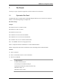
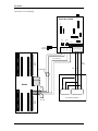
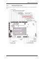
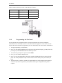
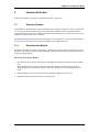
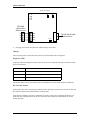
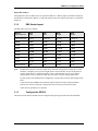
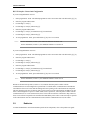
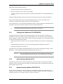
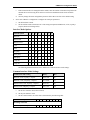
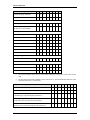
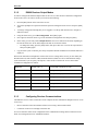
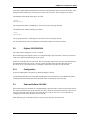
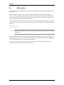
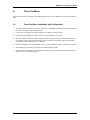
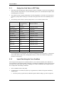
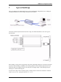
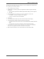
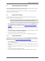
OEM Device Configuration Guide
Table of Contents
OEM Devices ....................................................................... 5
1. Fire Panels ............................................................................................. 7
1.1. Pyrotronics Fire Panel ......................................................................................... 7
1.2. Notifier AM2020 Fire Panel ................................................................................. 9
1.3. Notifier NFS-640 Fire Panel .............................................................................. 10
2. Intercom Exchanges ............................................................................ 13
2.1. Zenitel AlphaCom .............................................................................................. 13
3. Intrusion Detection ............................................................................... 15
3.1. Detection Systems ............................................................................................. 15
3.2. Radionics ........................................................................................................... 18
3.3. Downstream Devices ......................................................................................... 23
4. Personal Safety ................................................................................... 25
4.1. Visonic SpiderAlert ............................................................................................ 25
5. Receivers ............................................................................................. 27
5.1. Radionics D6500/D6600 Receiver .................................................................... 27
5.2. Digitize 3505/3500/3000 .................................................................................... 29
5.3. Osborne-Hoffman OH-2000 .............................................................................. 29
5.4. AES IntelliNet .................................................................................................... 30
Enrollment .......................................................................... 31
6. Corex CardScan .................................................................................. 33
6.1. Corex CardScan Installation and Configuration ................................................. 33
7. Cypress Data Wedge ........................................................................... 37
8. Intelli-Check ID-Check ......................................................................... 39
8.1. IDC1400 Configuration ...................................................................................... 39
8.2. B.A.S.I.S. Configuration ..................................................................................... 40
9. Topaz SignatureGem Pen Tablet ........................................................ 43
9.1. SignatureGem Installation ................................................................................. 43
revision 3 — 3
Table of Contents
IP Support .......................................................................... 45
10. LAN Connections ............................................................................... 47
10.1. Configuring a MSS1/MSS100 Ethernet Controller (BAS-ETHLAN) ................. 47
10.2. Device Configuration ....................................................................................... 51
Index .................................................................................................................. 53
4 — revision 3
OEM DEVICES
OEM Device Configuration Guide
1.
Fire Panels
Currently, two types of panels are supported: Pyrotronics (MXL series) and Notifier.
1.1.
Pyrotronics Fire Panel
Communication to the fire panel must be established through an RS-485 4-wire connection to a NIM-1R
module. Use the following settings to configure this.
Black Box Settings:
Jumpers:
W5 should be on B-C to set RTS/CTS/CD.
W8 should be on A-B to set 4-wire.
W9 should be on D to set ON.
W15 should be on A-B to set RTS/CD Enabled.
W16 should be on A to set 0 ms Turn Around Delay.
W17 should be on E to set 0.15 ms Driver Enable Hold.
W19 - NO JUMPER. This is for testing purposes only.
XW1A - Jumper-block must be installed here to set DCE Emulation Mode.
XW1B - Jumper-block must NOT be installed here (this would change mode to DTE Emulation).
Switches:
S1 - Out to set Normal
S2 - ON to set Terminated or OFF to set Not Terminated
S3 - OFF to set Not Biased.
Notes:
18 AWG minimum
80 Ohms maximum per pair
Use twisted pair or shielded twisted pair
Terminate the shields at the NIM-1R enclosure only
Maximum voltage: 9 V
Maximum current: 150 mA
revision 3 — 7
Fire Panels
Connect the wires accordingly.
W17
S1
A
A B C
W15
W19
A B C
A B C
W8
A B C D E
W16
B C D E
Black Box IC108A
W9
A B C D E
W5
A B C
BIAS
TERM.
S3
S2
RxB+
RxA-
TxB+
110 VAC
Transformer
TxA-
XW1B
XW1A
25-Pin Serial Connector
7
3
2
TB1
1 2 3 4
5 6
(max. 4000 feet)
NIM-1R
7 8 9 10 11 12 13 14 15 16
(max.
50 feet)
DO
NOT
USE
RTS
Rx
Tx
SUPERVISED
MOM-4
1 2 3 4 5 6
5
NIM-1R
7 8 9 10 11 12 13 14 15 16
TB3
8 — revision 3
2
3
DB 9 Pin Male
E.O.L.R.
120 OHM
DO
NOT
USE
7
3
2
DB 25 Pin Female
9 or 25 Pin Connector
Workstation (PC)
OEM Device Configuration Guide
1.2.
Notifier AM2020 Fire Panel
The Notifier panel requires a serial interface board in order to function. The SIB-232 or SIB-2048A may be
used.
1.2.1
Connecting the Fire Panel
The serial interface board is used to connect to the printer serial port (pins 1, 2, and 4 on P3) on the fire
panel.
•
Pin 1 is EIA-232 Reference.
•
Pin 2 is Transmit to PRN.
•
Pin 4 is Receive from PRN.
A DB-25 or DB-9 cable may also be used. Connect the pins as follows:
SIB pin
DB-25 pin
DB-9 pin
Pin 1
Pin 7 (GND)
Pin 5 (GND)
Pin 2
Pin 3 (RXD)
Pin 2 (RXD)
Pin 4
Pin 2 (TXD)
Pin 3 (TXD)
revision 3 — 9
Fire Panels
1.3.
Notifier NFS-640 Fire Panel
The NFS-640 is a fire panel integrating a CPU, power supply (6 A), and battery charger, combined with a
mounting chassis and cabinet. It connects to the host via a standard serial cable.
The NFS-640 panel has been approved for use with firmware version 002.000.002B/002.001.009A.
Important:
10 — revision 3
Due to hardware limitations, the connection of this device is unable to be
monitored. Therefore, B.A.S.I.S. will always report status of the Notifier NFS640 panel as being online (even when it is offline).
OEM Device Configuration Guide
1.3.1
Connecting the Fire Panel
Use a serial cable to connect the fire panel to the host. Wire the cable directly to the panel using terminal
TB14.
revision 3 — 11
Fire Panels
A DB-25 or DB-9 cable may be used. Connect the pins as follows:
TB14
DB-25 pin
DB-9 pin
TX
3 (Receive)
2
RX
2 (Transmit)
3
REF
7 (Ground)
5
1.3.2
Programming the Fire Panel
The fire panel must be programmed in order to recognize downstream devices such as intelligent/
addressable detectors and modules, Panel Circuits, and Notification Appliance Circuits (NACs). Use the
keypad connected to the panel for programming. For more information, refer to the Notifier documentation.
1.
To begin programming, press [ENTER.].
2.
Press [1] to enter the programming menu. At this point, if the panel starts beeping, you may silence it by
pressing the [ACKNOWLEDGE SCROLL DISPLAY] button.
3.
You will then be prompted for a password. Enter 00000.
4.
Press [1] to enter the Basic Program menu.
5.
Press [1] to start Auto-programming. This option identifies all addressable devices connected to the
panel. You will be prompted to accept or remove the device from memory as they are found by the
panel.
6.
After this process is complete, a summary of programmed devices will be displayed. Press [Enter] to
continue. If any alarms are generated, you may silence them again. Configuration of the panel is
complete.
12 — revision 3
OEM Device Configuration Guide
2.
Intercom Exchanges
For more detailed information, refer to the Zenitel user manual.
2.1.
Zenitel AlphaCom
A standard RS-232 cable is used to communicate between the host computer and the Zenitel (formerly
known as Stentofon) AlphaCom unit. Connect the RS-232 cable to the data port on the back of the
AlphaCom unit.
The integration requires that the AlphaCom exchanges have at least 7.10 firmware. Bi-directional
communication to the unit is used and this is only available in 7.10; earlier versions do not support this.
2.1.1
AlphaNet
Multiple exchanges can be connected together in a system referred to as AlphaNet. In order to place calls
from Alarm Monitoring, the following setting is required in the ACS.INI file:
[Stentofon]
AlphaNet=1
revision 3 — 13
Intercom Exchanges
14 — revision 3
OEM Device Configuration Guide
3.
Intrusion Detection
Follow the instructions for setting up an intrusion detection system below.
3.1.
Detection Systems
The DS7400Xi is an addressable control/communicator. Two versions are supported: version 4+ and version
3. For serial connections, the DS7412 RS-232 Serial Interface Module is used in conjunction with the
control/communicator. In order to establish communication with this panel over a direct connection or LAN
connection, a NULL modem cable is required.
The Intrusion Detection panel can also be configured over a LAN connection. For more information, refer to
the Detection Systems DS7400Xi in the section, OEM Devices Supported Over IP.
3.1.1
Serial Interface Module
The DS7412 provides the means for connecting to a serial device (such as a printer to print history events as
they occur or at a later time using a keypad command). The interface also allows for direct connection to a
computer for programming.
DS7412 Serial Interface Module
1.
Disconnect the power to the control panel by unplugging the transformer and removing the red battery
lead.
Before handling the circuit board, touch the control panel cabinet or another source of ground to
discharge any static electricity that may be in your body. Failing to do so could damage the circuit
board.
2.
Mount the DS7412 in the control panel enclosure using the supplied clips and screws.
3.
Install the program plugs and connect the wiring as shown.
revision 3 — 15
Intrusion Detection
Wiring the DS7412
OPT
Tx Rx
P4
P2
Tx Rx
SER
DS7400Xi
Options Bus
1000 feet max.
4.
R
RED
B
BLK
G
GRN
Y
YEL
RS-232 Serial Cable
50 feet max.
P3
Re-apply power and set the panel time and date using a master PIN.
Jumpers
There are three jumpers on the Detection Systems circuit board that must be configured.
Diagnostic LEDs
Jumper P2 controls the diagnostic LEDs, which can be used as a troubleshooting aid. To enable the LEDs,
place P2 on both pins.
OPT Tx
Option bus transmit date to control panel
OPT Rx
Option bus receive data from control panel
SER Rx
RS-232 receive data from printer
SER Tx
RS-232 transmit data to printer
The DS7412 draws more current in this mode so P2 should not be in place under normal circumstances.
RS-232 Cable Ground
Some printers may cause a ground fault condition on the control panel. If this occurs, remove P3. This will
disconnect the printer cable ground from the cabinet ground.
Some desktop computers can cause a ground fault even if P3 is removed. If connecting the DS7412 to a
desktop PC and a ground fault occurs, use the connection only temporarily and disconnect for normal
control operation.
16 — revision 3
OEM Device Configuration Guide
Option Bus Address
Add jumper P4 if there is another device at options bus address 14. When a jumper is installed on both pins,
the option bus corresponds to address 13. When the jumper is placed on only the bottom pin, it is option bus
address 14.
3.1.2
DB9 Socket Layout
The DB9 socket layout is as follows:
DS7412
9-pin connector
DCE
9-pin
DTE
9-pin
DCE
25-pin
DTE
25-pin
1 DCD (not used
1 DCD
1 DCD (6)
8 DCD
8 DCD (6)
2 RxD
2 Rxd
3 TxD
3 RxD
2 TxD
3 TxD
3 TxD
2 RxD
2 TxD
3 RxD
4 DTR
4 DTR
6 DSR
20 DTR
6 DSR
5 GND
5 GND
5 GND
7 GND
7 GND
6 DSR
6 DSR
4 DTR
6 DSR
20 DTR
7 RTS
7 RTS
8 CTS
4 RTS
5 CTS
8 CTS
8 CTS
7 RTS
5 CTS
4 RTS
9 RI (not used)
9 RI
9 RI
22 RI
22 RI
Note:
The DS7412 serial port is wired as a DTE device; therefore, if the printer is a DCE device (most
common), a straight 9-pin to 9-pin or straight 9-pin to 25-pin cable may be used. If the printer is
wired as a DTE device, a null modem 9-pin to 9-pin or a null modem 9-pin to 25-pin cable is
required. Refer to the user guide provided with your printer for proper wiring requirements.
If you are using a non-standard printer configuration, you must make a custom cable using the table
above.
Connections shown in bold are the minimum required connections when using XON/XOFF
software flow control. If using the configuration, these are the only connections needed.
Connections in (parentheses) are optional.
3.1.3
Configure the DS7412
The DS7412 serial interface module must be configured using the keypad connected to the DS7400Xi.
revision 3 — 17
Intrusion Detection
RS-232 Interface Control and Configuration
If you are using DS7400Xi version 3
1.
Enter programmers’ mode. The default programmers code is 9876. Enter this code followed by [#], [0].
2.
Enter the program address 0206.
3.
For data digit 1, enter [1].
4.
For data digit 2, enter [0] followed by [#].
5.
Enter the program address 0207.
6.
For data digit 1, enter [2] for 2400 baud or [4] for 9600 baud.
7.
For data digit 2, enter [5] followed by [#].
8.
To exit programmers’ mode, press and hold the [*] key for a few seconds.
Notes:
For the DS7400Xi (version 3), the minimum firmware version is 3.09.
For the DS7400Xi (version 4+), the minimum firmware is version 4.03.
If you are using DS7400Xi version 4+
1.
Enter programmers’ mode. The default programmers code is 9876. Enter this code followed by [#], [0].
2.
Enter the program address 4019.
3.
For data digit 1, enter [1].
4.
For data digit 2, enter [0] followed by [#].
5.
Enter the program address 4020.
6.
For data digit 1, enter [2] for 2400 baud or [4] for 9600 baud.
7.
For data digit 2, enter [5] followed by [#].
8.
To exit programmers’ mode, press and hold the [*] key for a few seconds.
Note:
For the DS7400Xi (version 4+), the minimum firmware version is 4.03.
Whenever the Detection Systems (version 3 or 4+) intrusion detection panel is online with the
communication server and configured to report alarms to a central station, communication to the DS7412
serial interface device will cease until the dialing and event reporting to the central station has completed.
This only happens in the case of alarm or panic report events sent to the central station. In addition, for any
other events configured to report to a central station, such as open/close, when the panel is online with the
communication server via the serial interface, these events will not cause the connection to drop. However,
these events will not be reported to the central station immediately either. These events will only be reported
to the central station once the communication session (with the communication server) has ended.
3.2.
Radionics
To install the Radionics control/communicator panel and its components, refer to the product user guide.
18 — revision 3
OEM Device Configuration Guide
Addressable expansion modules (D8125)
•
provide point identification for initiating devices.
•
supervise wiring to devices to ensure circuit integrity.
•
are used to expand the control/communicator beyond its standard number of on-board initiating zones
or points.
The D8125 module should be connected to the Zonex ports and powered by the control/communicator.
The Octo-relay module (D8129) provides eight programmable Form-C relays. This module is also
connected to the Zonex ports and powered by the control/communicator.
The Command Center is a keypad with an alphanumeric display, capable of distinct fire and burglary tones.
It should be connected to the data bus and powered by the control/communicator.
Note:
3.2.1
The Radionics D7412G and D9412G require firmware version 6.20.
Configure the Radionics D7412G/D9412G
Configuration of the D7412/D9412 must be done through the software provided by the manufacturer. A
D9133DC serial interface module is required (with the address set to 88). This device can be connected to
the host computer via a NULL modem cable. For more information on RAM IV, refer to the Radionics RAM
IV manual. Currently, RAM IV is used for:
•
Initial setup of the system (zones, areas, users, schedules, authority levels, functions, command centers,
etc.)
•
Adding/deleting/modifying users (also can be done through keypad commands on the panel)
•
Changing zone properties, schedules, etc.
The panel needs to be configured for SDI Automation. This is also done via the RAM IV software. Under
RADAUX1 > SDI Automation, Enable SDI Automation needs to be set to yes.
Important:
3.2.2
Do not install the RAM IV software on the same computer as the Detection
Systems Configuration software! Doing so will cause damage to your computer.
Serial Interface Module D9133
Communication between B.A.S.I.S. and the D9412/D7412 requires the D9133 (serial interface module).
This device can be connected to the host computer via a NULL modem cable. Set the address to 80 (the four
address jumpers need to be off).
3.2.3
Network Interface Module PC9133TTL-E
The PC9133TTL-E is used for a network connection to the Radionics panel in place of the D9133 and
Lantronix box. Set the address to 80 for SDI automation (no jumpers installed). The address configuration is
read only at power-up, so if a change is made, cycle power to the device.
revision 3 — 19
Intrusion Detection
Wiring
Connect the PC9133TTL-E to the Radionics D9412/D7412 as follows:
PC9133TTL-E connection
Panel connection
SDI PWR
POWER + (Terminal 32)
SDI A
DATA A (Terminal 31)
SDI B
DATA B (Terminal 30)
SDI COM
COMMON (Terminal 29)
Connect the PC9133TTL-E (RJ-45 connector) to the network.
Set Up a Temporary IP Address
Before using the network interface module, you must assign a unique IP address to it. In order to do this,
locate the MAC address on the label.
1.
Verify that there is at least one entry in the ARP table. To do so, at the command prompt, type
arp -g
•
If there are no entries other than the local machine, ping another machine (which must be a host
other than the machine on which you are working) on the network to build the ARP table.
2.
Use the ARP command to configure the IP address. Type
arp -s [IP Address] [Ethernet/Hardware Address]
where the IP address is a numerical address and the Ethernet/Hardware Address is the MAC address
found on the label attached to the PC9133TTL-E.
3.
Verify that the address was added to the table by typing
arp -g
The ARP command is used only to temporarily associate the IP address with the MAC address. To
permanently assign the IP address, telnet to the device and set it in the server configuration.
Assign the IP Address
1.
At the command prompt, telnet to port 1. Type
telnet [IP Address] 1
This first attempt at telnetting will fail.
2.
Telnet to port 9999. Type
telnet [IP Address] 9999
This second attempt at telnetting will be successful.
3.
Press <Enter> to go into setup mode.
4.
Select 0 for Server Configuration.
a.
Configure the IP address of the PC9133TTL-E. This is the same IP address used for the Radionics
Intrusion Panel in System Administration
b.
If a gateway IP address is needed, select Y and enter the information. This is only needed when
using a WAN. In a LAN, the gateway is not necessary and only needs to be changed if the gateway
IP of the PC is different than that of the PC9133TTL-E host.
20 — revision 3
OEM Device Configuration Guide
5.
c.
If the netmask needs to be changed from the default, enter the number of bits that correspond to the
netmask the network is using. Refer to the PC9133TTL-E Installation Guide for the available
values.
d.
You may change the telnet configuration password. Select N to leave this at the default setting.
Select 1 for Channel 1 Configuration. Configure the serial port parameters.
a.
Set the baud rate to 9600.
b.
Set the interface mode (I/F Mode) to 4C. This setting corresponds with RS-232C, 8-bit, no parity, 1
stop bit (shown in following tables).
Interface Mode Options
I/F mode option
7
6
5
4
3
2
1
0
RS-232C
0
0
RS-422/485
0
1
RS-485 2-wire
1
1
7-bit
1
0
8-bit
1
1
No parity
0
0
Even parity
1
1
Odd parity
0
1
1 stop bit
0
1
2 stop bit
1
1
The following table demonstrates how to build some common interface mode settings.
Common Interface Mode Settings
Common I/F mode setting
Binary
Hex
RS-232C, 8-bit, no parity, 1 stop bit
0100 1100
4C
RS-232C, 7-bit, even parity, 1 stop bit
0111 1000
78
RS-485 2-wire, 8-bit, no parity, 1 stop bit
0100 1111
4F
RS-422, 8-bit, odd parity, 1 stop bit
0101 1101
5D
c.
Set the flow control to 00 (no flow control).
d.
Set the port number to 3001.
e.
Set the connect mode to C0. This value is determined by the following table.
Connect mode option
7
6
5
0
0
0
4
3
2
1
0
Incoming connection
Never accept incoming
revision 3 — 21
Intrusion Detection
Connect mode option
7
6
5
Accept incoming with DTR
0
1
0
Accept unconditional
1
1
0
4
3
2
1
0
No active startup
0
0
0
0
With any character
0
0
0
1
With active DTR
0
0
1
0
With CR (0x0D) only
0
0
1
1
Manual connection
0
1
0
0
Autostart
0
1
0
1
1
1
0
0
Response
Nothing (quiet)
0
Character response (C=conn,
D=disconn, N=unreachable)
1
Startup
Hostlist
0
0
1
0
Datagram type
Directed UDP
Modem mode
Full verbose
1
0
1
1
0
Without echo
0
0
1
1
0
1-character response
1
0
1
1
1
f.
The remote IP address can be left at 0.0.0.0 and the remote port can be left at 0 since these are not
used.
g.
The disconnect mode (DisConnMode) can be either 00 or 01. This determined the behavior of the
state LED when there is a connection.
Disconnect mode option
7
Disconnect with DTR drop
1
Ignore DTR
0
Telnet mode and terminal type setup (The CoBox will send
“Terminal Type” upon an outgoing connection.)
Channel (port) password (A password is required for a
connection to the serial port from the network.)
Hard disconnect (The TCP connection will close even if the
remote site does not acknowledge the disconnection.)
22 — revision 3
6
5
4
3
1
1
0
2
1
0
OEM Device Configuration Guide
Disconnect mode option
7
6
5
Disable with hard disconnect
4
3
2
1
1
1
State LED off with connection (When there is a network
connection to or from the serial port, the state LED will turn
off instead of blink.)
Disconnect with EOT (^D) (When <Ctrl> + <D> or Hex 04
are detected, the connection is dropped. Both Telnet mode
and Disconnect with EOT must be enabled for Disconnect
with EOT to function properly. <Ctrl> + <D> will only be
detected going from the serial port to the network.)
h.
Set the flush mode to 00.
i.
Set the disconnect time (DisConnTime) to 00:00.
j.
For SendChar 1 and SendChar 2, the values can be set to 00.
0
1
6.
Select 5 for Expert Settings.
It is recommended that you set the TCP Keepalive time to 15 seconds. It is set to 0 by default. This
option specified the amount of time (during a silent connection) before attempting to check if the
network device is still online. If there is no response within this time period, the connection is dropped.
7.
Select 9 to save and exit.
3.3.
Downstream Devices
For any additional downstream devices supported, refer to the product user guide for wiring and
configuration.
revision 3 — 23
Intrusion Detection
24 — revision 3
OEM Device Configuration Guide
4.
Personal Safety
4.1.
Visonic SpiderAlert
The SLC-5 (SpiderAlert Local Controller) is the main controller designed for the SpiderAlert 5 alert
signaling network.
A standard RS-232 cable can be used to connect the host computer to the SLC-5 via the SLC-TO-SSK
Adapter. A six-wire cable with RJ-11 connectors at both ends is used to connect the SLC-TO-SSK Adapter
to the SLC-5.
B.A.S.I.S. currently supports the “Single-Site Direct Connection To Computer” operating mode. For this
mode, SW1 & SW2 dip switches need to be set to the ON position on the SLC-5.
revision 3 — 25
Personal Safety
26 — revision 3
OEM Device Configuration Guide
5.
Receivers
Follow the instructions for setting up receivers below. For additional information, refer to the receiver
manual.
5.1.
Radionics D6500/D6600 Receiver
These receivers are configurable for two output formats: SIA and 6500. Each of these modes handles the
default and SIA event code templates stored in the database differently. Therefore, an event that is generated
in 6500 mode would be reported in Alarm Monitoring differently than an event in SIA mode.
A NULL modem cable is required to connect a host computer to the D6500 receiver. The D6500 receiver is
programmed using the Radionics keypad. For more information, refer to the manufacturer manual.
The D6600 receiver connects via COM 3 on the back of the unit.
Note:
For a list of supported protocols, refer to the Radionics documentation.
5.1.1
D6500 Firmware Requirements
The Radionics D6500 requires a minimum firmware, based on the Main Processing Unit (MPU).
MPU number
Minimum firmware requirement
D6510
8.03
D6511
1.06
In order to determine the MPU number and firmware version, perform the following procedure:
1.
Disconnect the backup battery in the receiver.
2.
Turn the receiver power off.
3.
Wait 10 seconds.
4.
Turn the receiver back on.
5.
The LCD will display the line card, MPU, printer version, and firmware version.
D6500 receivers with a firmware that is lower than what is specified are not supported. If you attempt to
connect a receiver not meeting these specified requirements, the receiver will fail to come online in Alarm
Monitoring.
revision 3 — 27
Receivers
5.1.2
D6600 Receiver Output Modes
In order to configure the different output modes for the receiver, enter into the Automation Configuration
menu on the receiver. In order to do this you need to do the following:
1.
Press the [M/E] button on the front of the receiver.
2.
You will be prompted for a password. Enter the password configured for the receiver and press [M/E]
again.
3.
A message will appear indicating that you are logged in. Use the up and down arrows to navigate to
different sections.
4.
Using the down arrow, go to CPU Configuration. Press [M/E] again.
5.
Once again use the down arrow to go to the Automation Configuration item and press [M/E].
6.
In the menu, go to the entry labeled Output Format. One or two formats will be listed, depending on
the current format: one for the 6500 output mode and one for the SIA format.
•
7.
To change this setting, press the [M/E] button, then press either one or two for the output desired.
Then press [M/E] again.
Log out of the system. To do this, press the [CAN] button until the standard screen with date and time is
displayed.
When in the Automation Configuration section of the receiver settings in this screen, you can modify the
Heartbeat Interval, Start Character (HEX) and End Character (HEX) as well as communication settings
(such as baud rate, byte size, parity, and stop bits). These items are listed in the receiver menu under
Automation Configuration as follows:
Baud Rate
Default value = 4
Corresponds to baud rate of 1200
Data Bit
Default value = 8
Corresponds to byte size of 8
Parity
Default value = 0
Corresponds to parity of NONE
Stop Bit
Default value = 1
Corresponds to 1 stop bit
Link Test
Default value = 5
Corresponds to heartbeat interval of 5 seconds
Header
Default value = 1
Corresponds to start character of 1
Trailer
Default value = D
Corresponds to end character of D
5.1.3
Configuring Receiver Communications
The Radionics receiver can be connected to a host computer and can communicate through B.A.S.I.S. in one
of two ways:
•
Direct connection of the host machine and the receiver using a NULL modem cable
•
Connection of the receiver through a Lantronix box
If a LAN connection will be used, configuration of the communication settings in the Lantronix box will
differ from configuration for use with BEST hardware.
28 — revision 3
OEM Device Configuration Guide
You can also gather debug information when connected to the Radionics panel in 6500 or SIA modes. These
debug files can be turned on by creating a new section in the acs.ini file. These settings are as follows:
For Radionics 6500, add the following to ACS.INI
[6500]
6500Debug=1
The file generated will be “6500Debug.txt” and will be located in the logs directory.
For Radionics SIA, add the following to ACS.INI
[SIA]
SIADebug=1
The file generated will be “SIADebug.txt” and will be located in the logs directory.
For more information, refer to the Radionics Communications Receiver/Gateway manual.
5.2.
Digitize 3505/3500/3000
The output format of Digitize receivers is CAPS II.
When connecting to the Digitize System, use a straight through 9-pin serial cable. Connect one end of this
cable to the computer automation port of the system.
In the back of the unit, there are four cards. The one in the upper right corner is set up to send information to
the automation software (B.A.S.I.S.). You may connect the other end of the cable either directly toa
B.A.S.I.S. server or to a Lantronix box, configuring a connection to the panel over the network.
5.2.1
Configuration
In System Administration, the panel type should be Digitize CAPS II.
The default heartbeat interval is 40 seconds and should be fine for normal use. If you find that the panel is
switching back and forth between online and offline states, increasing this value may help.
5.3.
Osborne-Hoffman OH-2000
When connecting to the OH-2000, use a straight through 9-pin serial cable. Connect one end of this cable to
the computer automation port of the OH-2000. This port is located at the top left in the back of the receiver.
You may connect the other end of the cable either directly to a B.A.S.I.S. server or to a Lantronix box,
configuring a connection to the panel over the network.
Many different types of downstream devices can be used to report into the OH receiver.
revision 3 — 29
Receivers
5.4.
AES IntelliNet
B.A.S.I.S. integrates to the AES IntelliNet receiver when programmed to output using the Radionics 6500
output format.
The AES IntelliNet receiver can be connected to a host computer and can communicate through the
software. A direct connection can be made by making a serial connection between the host automation port
of the receiver and an available COM port on the host computer. For direct connections, the flow control
cannot be configured. This is hard-coded in the software.
For builds later than 5.10.309, the following changes are NOT needed. For build 5.10.309 and earlier, if you
are using a direct connection, a change must be made to the ACS.INI file. Make the following modification
to this file:
[Radionics6500]
DtrControl=1
Note:
With this setting in the ACS.INI file, a Radionics D6600 receiver cannot be used with the 6500
output mode.
The AES IntelliNet receiver must be configured for Radionics 6500 output mode. Also note that since the
AES receiver does not have a start character, zero (0) should be used. The end character must be 0x0014. For
more detailed instructions, refer to the AES IntelliNet manual.
A LAN connection can also be made by using a 9-pin to 25-pin connector and connecting this to the
Lantronix unit. For more information, refer to IP Support.
30 — revision 3
ENROLLMENT
OEM Device Configuration Guide
6.
Corex CardScan
These instructions are for installing and configuring either the Corex CardScan 300 or the Corex CardScan
600c.
6.1.
Corex CardScan Installation and Configuration
1.
Install the CardScan software on your PC. This must be done before connecting your scanner. To install
the scanner, refer to the Corex documentation.
2.
Connect the AC adapter to the scanner. Plug the AC adapter into a power outlet.
3.
Using the included USB cable, connect the scanner to the USB port on your PC.
4.
Start the CardScan software and make sure that the business card scanner is functional. Note that after
the CardScan software has been run initially, it does not need to be running in order for the business
card scanner to work with the B.A.S.I.S. software.
5.
Calibrate the business card scanner. Refer to the Corex documentation on how to calibrate the scanner.
6.
In FormsDesigner, assign the vCard value to user-defined fields (UDF).
7.
Use the business card scanner in the Cardholders folder in System Administration, ID CredentialCenter,
Digital Video, or Visitor Management.
revision 3 — 33
Corex CardScan
6.1.1
Assign the vCard Value to UDF Fields
1.
Start and log into FormsDesigner. When prompted, open the Cardholder or Visitor form, depending on
which you wish to map fields for. For more information, please refer to the Introduction chapter in the
FormsDesigner™ User Guide.
2.
The scanner will only recognize fields that are currently assigned the vCard value. The vCard value is
assigned by simply double-clicking on a field and selecting the field’s name in the vCard drop-down
list.
3.
The following vCard fields are currently mapped to the Corex CardScan scanner fields:
vCard value
Field vCard value
is assigned to by
default
FormsDesigner form(s) the
field is located on
First Name
First name
Cardholder, Visitor
Home Telephone
Phone
Cardholder
Internet Email
E-mail
Cardholder
Last Name
Last name
Cardholder, Visitor
Middle Name
Middle name
Cardholder, Visitor
Organization Name
Organization
Visitor
Title
Title
Cardholder, Visitor
Work City
City
Cardholder, Visitor
Work State
State
Cardholder, Visitor
Work Street
Address
Cardholder, Visitor
Work Telephone
Office phone
Cardholder, Visitor
Work Zip
Zip code
Cardholder, Visitor
If a vCard property is not assigned to any field on a FormsDesigner form by default (i.e., Name Prefix,
Name Suffix, Work Country, Fax, and Organization Name), a field can be added and assigned that
particular vCard property.
6.1.2
Import Data Using the Corex CardScan
You can import data using the Corex CardScan whenever you are asked to manually enter cardholder or
visitor information. This includes adding, modifying, or searching for cardholder or visitor records. You can
also import in the Visits folder when you are searching for a visitor or cardholder. This example describes
how to import data when adding a cardholder.
1.
In the Cardholders folder, click [Add].
2.
If segmentation is not enabled, skip this step. If segmentation is enabled, the Segment membership
window opens.
a.
Select the primary segment and any additional segments that this badge type will be assigned to.
34 — revision 3
OEM Device Configuration Guide
b.
3.
Click [OK].
In the Person type field, select whether the record will be cardholder or a visitor record.
•
If “Cardholder” is selected, the Cardholder form is displayed.
•
If “Visitor” is selected, the Visitor form is displayed.
4.
Place a business card, face down, in the business card scanner.
5.
Click [Import].
6.
The Select Import Source window opens. Select “Corex CardScan scanner,” then click [OK].
7.
The scanner will scan the business card, and the fields on the Cardholder or Visitor form will be
populated with whatever information can be determined.
8.
Make sure that the information is correct, then click [OK]. The record will then be added.
revision 3 — 35
Corex CardScan
36 — revision 3
OEM Device Configuration Guide
7.
Cypress Data Wedge
The Cypress Wedge (part number WDG-4413) is used to add automatic Wiegand data entry to badging or
enrolling workstations. It converts badge information into keystrokes.
Connect the terminal, keyboard, and reader to the wedge. For detailed information, refer to the Cypress
documentation.
When a badge is swiped, the five digit facility code and five digit badge number are converted to equivalent
keystrokes. When enrolling a cardholder (after clicking [Add]), the cursor should be placed in the correct
field for the data to be populated. If this is not done prior to swiping a badge, a Search dialog will open,
allowing for a search on the badge ID.
In order for the wedge reader to function properly, a change must be made in the ACS.INI file. Under the
section [WEDGESCAN], specify the value for StartByte.
revision 3 — 37
Cypress Data Wedge
38 — revision 3
OEM Device Configuration Guide
8.
Intelli-Check ID-Check
The information on a driver’s license, military ID, or passport can be imported using an ID-Check IDC1400
terminal. ID-Check can read, analyze, and verify the information encoded in the bar codes and magnetic
stripes on state and provincial driver licenses, identification cards, military and government IDs including
those that conform to the standards of the American Association of Motor Vehicle Administrators
(AAMVA), American National Standards Institute (ANSI) and International Organization for
Standardization.
Note:
The IDC1400 must be running firmware version 5.4 or later.
Connect the IDC1400 to the workstation using a serial cable.
8.1.
IDC1400 Configuration
Once the unit is connected and powered, the terminal will immediately display “ID-CHECK SETUP
REQUIRED.” To access the setup menu, press SETUP [F6]. Key in your four-digit master password and
press [Enter].
Once you access the Setup menu, selections can be made by pressing [Enter]. Use the up and down buttons
to scroll through options. Use any of the arrow keys to toggle settings.
8.1.1
Configure the Host Port
Configure the IDC1400 to send transaction results through the printer port.
1.
2.
In the SETUP [F6] menu use the UP and DOWN arrows to scroll through the options. Select
FEATURES by pressing [Enter], then scroll through and select PRINTER. Press [Enter]. Set the
following attributes as follows:
a.
MODE: Enabled (to enable the printer)
b.
BUSY CHECK: Disabled
c.
PRE LINES = 00 (number of line feeds to send before each transaction result)
d.
POST LINES = 03 (# of line feeds to send after each transaction result)
e.
PRINT TEXT = LEFT MARGIN (parser friendly format for applications)
In the SETUP [F6] menu, under FEATURES > PRINTER > HOST PORT, set BAUD RATE,
PARITY, WORD LENGTH, and FLOW CONTROL to the appropriate values to match your B.A.S.I.S.
communication settings.
revision 3 — 39
Intelli-Check ID-Check
8.1.2
Configure the Display
If the results do not need to be displayed on the terminal, disable this option to speed up the transaction time.
When a license is swiped or scanned, the IDC1400 will beep (if enabled) and transfer the data (if the printer
is enabled) and return back to the idle screen.
1.
In the SETUP [F6] menu use the UP and DOWN arrows to scroll through the options. Select
FEATURES by pressing [Enter].
2.
Scroll through and select DISPLAY TIME.
3.
Set the DISPLAY TIME = 00.
8.2.
B.A.S.I.S. Configuration
Before continuing, verify that you have a B.A.S.I.S. license with ID-Check Terminals enabled. The ability to
use ID-Check Terminals is a licensed feature. The ID-Check Terminals license is count-based; you are
licensed to have a certain number of ID-Check Terminals. The number of terminals you are licensed to use is
displayed in the “Maximum Number of ID-Check Terminals” setting in the ID CredentialCenter section of
the license.
The workstation to which the ID-Check scanner will be attached must be added in the B.A.S.I.S. software.
This is done in System Administration or ID CredentialCenter on the Workstations form.
The ID-Check scanner must also be added in the B.A.S.I.S. software. This is done in System Administration
or ID CredentialCenter on the Encoders/Scanners form in the Workstations folder. The encoder/scanner that
is added must have a Device Type of “ID-Check Terminal.”
Use FormsDesigner to map the proper DMV values to the data fields for enrollment.
The settings for the software must match the communication parameters configured on the IDC1400 unit.
Configure the communication parameters in System Administration as follows:
•
BAUD RATE: 38400
•
DATA BITS: 8 bit
•
PARITY: None
•
STOP BITS: 1
•
FLOW CONTROL: None
8.2.1
Import Data Using the ID-Check Scanner
You can import data using the ID-Check Scanner whenever you are asked to manually enter cardholder or
visitor information. This includes adding, modifying, or searching for cardholder or visitor records. You can
40 — revision 3
OEM Device Configuration Guide
also import in the Visits folder when you are searching for a visitor or cardholder. This example describes
how to import data when adding a cardholder.
1.
In the Cardholders folder, click [Add].
2.
If segmentation is not enabled, skip this step. If segmentation is enabled, the Segment membership
window opens.
3.
a.
Select the primary segment and any additional segments that this badge type will be assigned to.
b.
Click [OK].
In the Person type field, select whether the record will be cardholder or a visitor record.
•
If “Cardholder” is selected, the Cardholder form is displayed.
•
If “Visitor” is selected, the Visitor form is displayed.
4.
Click [Import].
5.
The Select Import Source window opens. Select “ID-Check Terminal”, then click [OK].
6.
An ID-Check message is displayed. Follow the instructions on the message.
•
If a magnetic stripe is present, swipe the driver’s license through ID Check’s Magnetic Stripe Slot
Reader.
•
If a barcode (2D or 1D) is present, scan the driver’s license using the barcode scanner.
7.
After the ID has been scanned, the message automatically closes. The fields on the Cardholder or
Visitor form will be populated with whatever information can be determined.
8.
Make sure that the information is correct, then click [OK]. The record will then be added.
revision 3 — 41
Intelli-Check ID-Check
42 — revision 3
OEM Device Configuration Guide
9.
Topaz SignatureGem Pen Tablet
The Topaz SignatureGem™ hardware is used to electronically capture cardholder signatures and connects
directly to a multimedia capture workstation via a USB or serial port.
These installation instructions and driver information are for the Topaz 1" x 5" SignatureGem USB (ZTS261-USB) and serial kit (Z-TS261-B).
9.1.
SignatureGem Installation
The Topaz SignatureGem pen tablet can be installed on any multimedia capture workstation running
Windows 2000 or XP. It is also compatible with Citrix.
Note:
Do NOT connect the signature tablet to the serial or USB port until prompted to do so.
1.
Install the Wintab drivers for the Topaz SignatureGem pen tablet. You can run the Wintab15.exe file in
the Topaz SignatureGem Pen Template Driver folder on the B.A.S.I.S. ET Third Edition Disk 2 or
download the drivers from the Topaz website located at http://www.topazsystems.com/Software/
index.htm#6.
2.
After the driver is installed, the PC will reboot. Connect the SignatureGem pen tablet to the correct port
(USB or serial).
3.
The Found New Hardware wizard should automatically start. If it does not, manually start the wizard by
selecting Start > Settings > Control Panel > Add Hardware.
4.
Complete all the steps in the Found New Hardware wizard.
5.
The SignatureGem pen tablet can now be used with the B.A.S.I.S. Multimedia Capture module.
9.1.1
Load the Wintab Driver
The Wintab driver information for the pen tablet is located in the Topaz SignatureGem Pen Template
Driver folder on the B.A.S.I.S. ET Third Edition Disk 2. You can also download the driver information from
the Topaz website, located at http://www.topazsystems.com/Software/index.htm#6.
1.
Run the Wintab15.exe file located in the Topaz SignatureGem Pen Template Driver folder on the
B.A.S.I.S. ET Third Edition Disk 2.
2.
The welcome screen for the Topaz 1x5 Tablet Win Tab Driver v2.12 Setup program window displays.
Click [Next].
3.
The Topaz Wintab Installation window displays. Select the port the signature tablet will connect to and
click [OK].
4.
Verify the Signature tablet is unplugged and click [OK].
5.
The next screen explains what you should do after the driver installation is complete. Click [OK].
revision 3 — 43
Topaz SignatureGem Pen Tablet
Note:
If you are asked to specify the driver location you can download the latest driver from http://
www.topazsystems.com/Software/index.htm#6.
6.
When the driver has been successfully installed, click [Finish].
7.
You will be prompted to restart the PC. Click [OK] to automatically restart the computer.
9.1.2
1.
Install the Topaz software
When the PC reboots, the Found New Hardware Wizard automatically displays. Select the Install the
software automatically (Recommended) radio button and click [Next].
Note:
If Found New Hardware wizard does not automatically start you can manually start it by
selecting Start > Settings > Control Panel > Add Hardware.
2.
You may receive a message stating the hardware has not passed Windows Logo testing. Click [Continue
Anyway] if you are installing the hardware on a machine that uses the Windows 2000 or XP operating
system.
3.
Click [Finish] when the wizard has finished installing the software.
44 — revision 3
IP SUPPORT
OEM Device Configuration Guide
10.
LAN Connections
The following information can be used to configure communication for Apollo panels, Pyrotronics,
Stentofon, receivers, and Visonic over LAN connections.
10.1.
Configuring a MSS1/MSS100 Ethernet Controller (BASETHLAN)
This Ethernet controller is a network device, and not a part of the UL certification. This device must have
transient protection.
(A NULL MODEM CABLE IS REQUIRED)
10.1.1
Notes:
Establish Serial Communication with the ETHLAN:
BEST now has the controller-to-MSS100 or MSS1-T cable available, part number HOCETHLAN.
UL requirement: This device must be on the recommended UPS (#HO2070) or equivalent
1.
With the power ON to the ETHLAN devices, establish a serial connection from the ETHLAN to the
PC’s Serial Communication Port, for example, using the HyperTerminal. (A Null Modem cable is
required.)
2.
Start HyperTerminal.
revision 3 — 47
LAN Connections
Lantronix Telnet session
3.
At this point, press the <Enter> key. (It may take a few seconds to complete booting).
•
Power should be cycled to the device while connected to it in order to see the “Load Completed...”
message.
•
If it appears that nothing changes after pressing the <Enter> key, it is possible that the Lantronix
MSS1 or MSS100 device was already configured once. If this occurs, you need to press the
<Enter> key before the phrase, “Load Completed-Boot in Progress” appears. If this still does not
allow you to enter into the command mode, you may also telnet into the Lantronix device.
•
If the device was configured previously, it may be best to do a hard reset and configure it from
scratch. To do this:
•
4.
a.
Using the end of a paper clip, or a similar small object, hold down the reset button.
b.
Cycle power to the device.
A prompt that says Local_1> should appear. If the prompt says Boot>, then the Ethernet
Address has not been defined and you must enter one.
a.
At the Boot> prompt, type change hardware n, where n represents the last three
digits of the Ethernet Address located on the bottom of the Lantronix box (Example: change
hardware 21-01-65).
b.
Reboot for the change to take effect.
c.
Wait for it to finish loading. Once it’s done, you should see a screen resembling the picture on
the previous page.
You will be prompted for a user name. Enter any name.
48 — revision 3
OEM Device Configuration Guide
10.1.2
Establishing Network Communications:
After a factory default reset, the following changes must be made:
1.
At the prompt, type:
set privileged and press <Enter>.
2.
Type in the password:
system and press <Enter>.
3.
Determine and set the IP address. Type:
change ipaddress [IP ADDRESS] and press <Enter>.
4.
Set the Gateway. Type:
change gateway [GATEWAY] and press <Enter>.
5.
Set the boot flags. Type:
change bootp disabled and press <Enter>
change dhcp disabled and press <Enter>
change rarp disabled and press <Enter>
6.
Set the access type to remote. Type:
change access remote and press <Enter>
7.
At the prompt, type:
logout and press <Enter>.
8.
Exit from HyperTerminal and cycle power to the device.
revision 3 — 49
LAN Connections
10.1.3
Configuring the ETHLAN
Any additional changes specific to the hardware that the Lantronix box is connecting to should be made
now. These may include, but are not limited to, baud rate, parity, stop bit, byte size, and flow control.
1.
Make sure the device is powered, completely booted, and connected to the network. Start
HyperTerminal.
2.
Connect to the device using the IP address, port 7000 (terminal type VT100). Example:
3.
A HyperTerminal session starts. Type:
access and press <Enter>. The access command will not echo.)
4.
You will be prompted for a user name. Enter any name. There should be a command prompt.
5.
Type:
set privileged and press <Enter>.
6.
The password prompt will appear. The password is system.
7.
For parity, type:
change parity [PARITY] <Enter>, where [PARITY] = none, even, odd, mark, or space.
8.
For stop bits, type:
change stopbits [BITS] <Enter>, where [BITS] = 0, 1, or 2.
9.
For byte size, type:
change charsize [SIZE] <Enter>, where [SIZE] = 7 or 8.
10. For flow control, type:
change flow control [FLOW CONTROL] <Enter>, where [FLOW CONTROL] = xonoff, ctsrts,
slowcts, or none.
11. For baud rate, type:
change speed [SPEED] <Enter>, where [SPEED] = the baud rate (9600, 2400, etc.)
50 — revision 3
OEM Device Configuration Guide
10.2.
Device Configuration
For a complete list of configuration options, refer to the Lantronix reference manual. At this point, the
Lantronix box should be ready to act as a gateway between a LAN and a serial device. It is also necessary to
wire and configure each individual device.
For wiring between the hardware and the Lantronix box, a straight through RS-232 cable is used. Also, a 25pin/9-pin adapter may be required for certain hardware. The Lantronix box is equipped with a 25 pin male
connector.
Device
access
parity
stop
bits
byte
size
flow
control
baud rate
AES IntelliNet (Radionics
6500 output mode)1
remote
odd
2
7
CTS/RTS
1200
Apollo panel
remote
none
1
8
none
9600/4800/2400/1200
Detection Systems DS7400Xi
remote
none
1
8
CTS/RTS
2400/9600
Digitize System 3505/3500/
3000
remote
none
1
8
none
1200
Notifier panel
remote
even
1
7
none
2400
Osborne-Hoffman OH-2000
remote
none
1
8
CTS/RTS
9600
Pyrotronics2
remote
even
1
7
none
115200/57600/38400/
19200/9600/4800/
2400/1200
Radionics D6600/D6500
remote
none
1
8
CTS/RTS
38400/19200/9600/
4800/2400/1200
Radionics D7412/D94123
remote
none
1
8
none
9600
Zenitel AlphaCom
remote
even
1
7
none
9600
Visonic
remote
none
1
8
CTS/RTS
9600
Note:
Be sure to match the baud rate setting with the baud rate for which the hardware is configured.
1.
A start character of 0 should be used, with an end character of 0x0014.
2.
For Pyrotronics, an additional RS-232/RS-485 adapter is needed.
3.
SDI Automation must be enabled on this panel. This is done via the RAM IV software in RADAUX1 >
SDI Automation > Enable SDI Automation = Yes. When using a D9133 with this device, the D9133
should be connected to the host with a null modem cable.
revision 3 — 51
LAN Connections
52 — revision 3
OEM Device Configuration Guide
Index
O
A
AES IntelliNet receiver.......................................
AlphaCom ...........................................................
Alphanet..............................................................
Apollo .................................................................
51
51
13
51
OEM devices......................................................... 5
OEM devices supported over IP ......................... 45
Osborne-Hoffman OH-2000 receiver ................. 51
P
D
D6500..................................................................
D6600..................................................................
Device configuration...........................................
Digitize System 3500 receiver ............................
DS7400Xi ...........................................................
DS7400Xi control/communicator panel .............
DS7412
diagnostic LEDs...........................................
installation ...................................................
jumpers ........................................................
option bus address........................................
27
27
51
51
51
15
16
15
16
17
Personal safety .................................................... 25
Pyrotronics ..................................................... 7, 51
Pyrotronics Fire Panel........................................... 7
R
Radionics ............................................................
D9133 ..........................................................
Radionics D7412/D94123...................................
Radionics receiver...............................................
Receivers.............................................................
RS-232 cable ground ..........................................
18
19
51
27
27
16
S
E
Enrollment devices ............................................. 31
Ethernet controller .............................................. 47
ETHLAN ............................................................ 47
SignatureGem pen tablet
installation checklist .................................... 43
load the Wintab driver ................................. 43
V
F
Fire panels............................................................. 7
Visonic ................................................................ 51
Visonic SpiderAlert ............................................ 25
I
Z
Install
Topaz software.............................................
Intercom exchanges ............................................
Intrusion detection ..............................................
DS7400Xi ....................................................
Intrusion detection panel DS7400Xi...................
44
13
51
15
51
Zenitel AlphaCom........................................ 13, 51
L
LAN connections ................................................ 47
M
MOM-4 ................................................................. 7
MSS1 .................................................................. 47
MSS100 .............................................................. 47
N
Notifier AM2020 .................................................. 9
Notifier panel ...................................................... 51
revision 3 — 53
P.O. Box 5044
Indianapolis, IN 46250
Phone: (317) 849-2250
B.A.S.I.S.® ET OEM Device Configuration Guide
Product version 5.10.419, item number E855, revision 3, 1/6/2004
Content of this document copyright © 2003 & 2004 by Lenel Systems International, Inc. BadgeDesigner™,
FormsDesigner™, and MapDesigner™ are trademarks used by Best Access Systems with permission from Lenel
Systems International, Inc. MS-DOS, Windows, Windows 98, and Windows NT are trademarks of Microsoft
Corporation. Integral and FlashPoint are trademarks of Integral Technologies, Inc. Crystal Reports for Windows is a
trademark of Crystal Computer Services, Inc. Oracle is a registered trademark of Oracle Corporation. Other product
names mentioned in this document may be trademarks or registered trademarks of their respective companies and are
hereby acknowledged.
Information in this document is subject to change without notice. The hardware described in this document is
furnished under a license agreement and may only be used is accordance with the terms of that agreement. No part of
this document may be reproduced or transmitted in any form or by any means, electronic or mechanical, for any
purpose, without the express written permission of the authors.
Warranty
Best Lock Corporation warrants that the product is free from defects in material and workmanship under normal use
and service with proper maintenance for one year from the date of factory ship. Best Lock Corporation assumes no
responsibility for products damaged by improper handling, misuse, neglect, improper installation, over-voltages,
repair, alteration, or accident. This warranty is limited to the repair or replacement of the defective unit. In no event
shall Best Lock Corporation be liable for loss of use or consequential damages of any kind, however occasioned.
There are no expressed warranties other than those set forth herein. Best Lock Corporation does not make, not
intends, nor does it authorize any agent or representative to make any other warranties or implied warranties, and
expressly excludes and disclaims all implied warranties of merchantability or fitness for a particular purpose.
Returned units are repaired or replaced from a stock of reconditioned units. All returns must be accompanied by a
return authorization number (RMA) obtained from the Best Lock Corporation customer service department prior to
returning or exchanging any product. The RMA number must appear on the outside of the shipping box and on the
packing slip. Any items returned without an RMA number will not be accepted and will be returned at the customer's
expense. All returns must have transportation, insurance, and custom brokers' fees paid.
Liability
It is expressly understood and agreed that the interface should only be used to control exits from areas where an
alternative method for exit is available. This product is not intended for, nor is rated for operation in life-critical
control applications. Lenel Systems International and Best Lock Corporation are not liable under any circumstances
for loss or damage caused by or partially caused by the misapplication or malfunction of the product. The liability of
Lenel Systems International and Best Lock Corporation does not extend beyond the purchase price of the product.