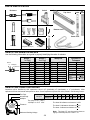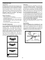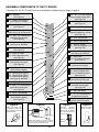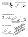
1
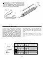
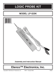
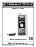
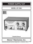
LOGIC PROBE KIT
MODEL LP-535K
Instruction & Assembly Manual
Elenco Electronics, Inc.
Copyright © 1999 Elenco Electronics, Inc.
Revised 2002
REV-A
753272
PARTS LIST
If you are a student, and any parts are missing or damaged, please see instructor or bookstore.
If you purchased this kit from a distributor, catalog, etc., please contact Elenco Electronics (address/phone/email is at the back of this manual) for additional assistance, if needed. DO NOT contact your place of purchase
as they will not be able to help you.
RESISTORS
Qty.
1
4
2
1
1
1
1
Symbol
R4
R5, R6, R7, R9
R1, R11
R10
R3
R2
R8
Description
470Ω 1/4W 5%
1kΩ 1/4W 5%
20kΩ 1/4W 5%
33kΩ 1/4W 5%
560kΩ 1/4W 5%
1MΩ 1/4W 5%
15MΩ 1/4W 5%
Qty.
1
1
2
1
1
1
1
1
Symbol
C1
C2
C3, C4
C6
C7
C5
C8
C9
Value
68pF
220pF
.001µF
.01µF
.1µF
.47µF 50V
47µF 10V
47µF 50V
Color Code
yellow-violet-brown-gold
brown-black-red-gold
red-black-orange-gold
orange-orange-orange-gold
green-blue-yellow-gold
brown-black-green-gold
brown-green-blue-gold
Part #
134700
141000
152000
153300
165600
171000
181500
CAPACITORS
Description
Discap (68)
Discap (220)
Discap (102)
Discap (103)
Discap (104)
Electrolytic (Lytic)
Electrolytic (Lytic)
Electrolytic (Lytic)
Part #
216816
222210
231036
241031
251010
254747
274742
274747
SEMICONDUCTORS
Qty.
2
4
1
1
1
1
1
1
Symbol
D8, D10
D2, D3, D4, D9
D1
D5
D6
D7
U2
U1
Value
1N4001
1N4148
1N5232
L-323 GD
L-323 ID
L-934 YDT
3086
74HC14
Description
Diode (epoxy)
Diode (glass)
Zener Diode 5.6V (bag with capacitors)
LED Green Triangular
LED Red Triangular
LED Yellow
Integrated Circuit
Integrated Circuit
Qty.
1
1
1
1
1
2
1
1
1
4”
0.6”
1
Symbol
Description
PC Board
Speaker 40Ω
Switch Slide SPDT
Logic Probe Tip
Case (two parts)
Socket IC 14-pin
Label
Manual
Cord Power
Tubing #20
Shrink Tubing Red 3/32”
Solder Tube
Part #
314001
314148
315232
35323G
35323I
359344
333086
39HC14
MISCELLANEOUS
SP1
S1
U1, U2
-1-
Part #
517030
521602
541025
616000
623019
664014
724009
753272
863080
890020
891020
9ST4
PARTS IDENTIFICATION
Resistors
Switch
Diodes
PC
Label Board
Top Cover
Epoxy
Capacitors
Glass
LEDs
Tubing
Speaker
+
Bottom Cover
Discap
Yellow
Green
Red
Integrated Circuits
Electrolytic
Integrated Circuit (IC)
Tip
Power Cord
IC Socket
IDENTIFYING RESISTOR VALUES
Use the following information as a guide in properly identifying the value of resistors.
BAND 1
1st Digit
Bands
1 2 Multiplier
Tolerance
Color
Black
Brown
Red
Orange
Yellow
Green
Blue
Violet
Gray
White
Digit
0
1
2
3
4
5
6
7
8
9
BAND 2
2nd Digit
Color
Black
Brown
Red
Orange
Yellow
Green
Blue
Violet
Gray
White
Digit
0
1
2
3
4
5
6
7
8
9
Multiplier
Resistance
Tolerance
Color
Multiplier
Black
1
Brown
10
Red
100
Orange
1,000
Yellow
10,000
Green
100,000
Blue
1,000,000
Silver
0.01
Gold
0.1
Color
Silver
Gold
Brown
Red
Orange
Green
Blue
Violet
Tolerance
+10%
+5%
+1%
+2%
+3%
+.5%
+.25%
+.1%
IDENTIFYING CAPACITOR VALUES
Capacitors will be identified by their capacitance value in pF (picofarads), nF (nanofarads), or µF (microfarads). Most
capacitors will have their actual value printed on them. Some capacitors may have their value printed in the following manner.
First Digit
Second Digit
Multiplier
103K
Tolerance
Multiplier
For the No.
0
1
2
3
Multiply By
1
10
100
1k
The value is 10 x 1,000 =
10,000pF or .01µF 100V
4
5
8
10k 100k .01
9
0.1
The letter M indicates a tolerance of +20%
The letter K indicates a tolerance of +10%
100V
The letter J indicates a tolerance of +5%
Note: The letter “R” may be used at times to
signify a decimal point; as in 3R3 = 3.3
Maximum Working Voltage
-2-
CIRCUIT DESCRIPTION
The Elenco Model LP-535 Logic Probe Kit is a
convenient and precise instrument for use in the
measurement of logic circuits. It displays logic levels
(high or low), sounds high level, and voltage
transients down to 10 nanoseconds. To detect the
high and low logic levels, the LP-535 uses two
inverters, U1A and U1B (see the Schematic
Diagram). One inverter drives the LO (green) LED
and the other, the HI (red) LED.
and additional components. The outputs of U1A and
U1B are connected to differential circuits C3/R3 and
C4/R7. These differential circuits select signals,
when the test signals are the pulses. After the
differential circuits, the short pulses go through
inverters U1C and U1D to the yellow LED. This LED
blinks when the detecting diode D4 opens. At this
time, capacitor C6 discharges. The lit time of the
yellow LED depends upon the value of C6. The LP535 is equipped with a sound circuit. When the input
signal is HI, the oscillator (U1E, U1F) is started and
the frequency through switch S1 passes to the
speaker.
The red LED lights when the input voltage is more
than 50% of the supply voltage. The function of the
switch for TTL or CMOS levels input signal makes up
the special circuit on the base of transistors from U2
SPECIFICATIONS
The LP-535 Logic Probe Kit tests different types of digital logic circuit families.
Working Voltage
Current Consumption
Frequency Response
Minimum Detectable
Pulse Width
Input Impedance
Input Overload Protection
Supply Voltage Protection
Operation Temperature
Switch
4 - 16VDC
Max 5mA @ 5V
Max 15mA @ 15V
Over 50MHz
10nsec
1MΩ
70V AC/DC (10s)
50V AC/DC (10s)
0OC to 50OC
Selectable Audio Indicator HI Level
This information for switch to the sound position.
Interpreting
the LEDs
*
INPUT
SIGNAL
LO
LED STATES
HIGH PULSE
SOUND
Probe not connected to power.
LED On
Logic tip is not connected or Logic “0” no
pulse activity.
LED Off
Logic “1” no pulse activity.
*
*
LED Blinking
No Sound
Logic “0” with positive single pulses.
Logic “1” with negative single pulses.
Logic “0” with positive continuous pulses.
Sound
Logic “1” with negative continuous pulses.
-3-
CONSTRUCTION
Introduction
Soldering
Assembly of your LP-535 Logic Probe Kit will prove to be
an exciting project and give you much satisfaction and
personal achievement. If you have experience in soldering
and wiring techniques, then you should have no problem
with the assembly of this kit. Care must be given to
identifying the proper components and in good soldering
habits. Above all, take your time and follow these easy
step-by-step instructions. Remember, “An ounce of
prevention is worth a pound of cure”. Avoid making
mistakes and no problems will occur.
The most important factor in assembling your logic probe
kit is good soldering techniques. Using the proper
soldering iron is of prime importance. A small pencil type
soldering iron of 25 - 40 watts is recommended. The tip of
the iron must be kept clean at all times and well
tinned. Many areas on the PC board are close together
and care must be given not to form solder shorts. Size
and care of the tip will eliminate problems.
For a good soldering job, the areas being soldered must
be heated sufficiently so that the solder flows freely. Apply
the solder simultaneously to the component lead and the
component pad on the PC board so that good solder flow
will occur. Be sure that the lead extends through the
solder smoothly indicating a good solder joint. Use only
rosin core solder of 63/37 or 60/40 alloy.
DO NOT USE ACID CORE SOLDER! Do not blob the
solder over the lead because this can result in a cold
solder joint.
Safety Procedures
• Wear eye protection when soldering.
• Locate soldering iron in an area where you do not have to
go around it or reach over it.
• Do not hold solder in your mouth. Solder contains lead
and is a toxic substance. Wash your hands thoroughly
after handling solder.
• Be sure that there is adequate ventilation present.
Heat Sinking
Assemble Components
Electronic components such as transistors, IC’s, and
diodes can be damaged by the heat during soldering. Heat
sinking is a way of reducing the heat on the components
while soldering. Dissipating the heat can be achieved by
using long nose pliers, an alligator clip, or a special heat
dissipating clip. The heat sink should be held on the
component lead between the part and the solder joint.
In all of the following assembly steps, the components
must be installed on the top side of the PC board unless
otherwise indicated. The top legend shows where each
component goes.
The leads pass through the
corresponding holes and the board is turned to solder the
component leads on the foil side. Solder immediately
unless the pad is adjacent to another hole which will
interfere with the placement of the other component. Cut
excessive leads with a diagonal cutter. Then, place a
check mark in the box provided next to each step to
indicate that the step is completed. Be sure to save the
extra leads for use as jumper wires if needed.
Soldering Iron
Solder
PC Board
Foil Side
Heat Sensitive
Component (Diode)
Heat Sink (this can be ordered as part of Elenco’s Solder Ease
Mount Part
Kit Model SE-1).
Bend Leads to Hold Part
Solder and Cut Off Leads
Rx - 100Ω 5% 1/4W Resistor
(brown-black-brown-gold)
-4-
A poorly soldered joint can greatly affect small current flow in circuits and can cause equipment failure. You can
damage a PC board or a component with too much heat or cause a cold solder joint with insufficient heat.
Sloppy soldering can cause bridges between two adjacent foils preventing the circuit from functioning.
What Good Soldering Looks Like
Types of Poor Soldering Connections
A good solder connection should be bright, shiny,
smooth, and uniformly flowed over all surfaces.
1. Insufficient heat - the solder will not flow onto
the lead as shown.
Soldering a PC board
Rosin
1. Solder all components from the copper foil side
only. Push the soldering iron tip against both the
lead and the circuit board foil.
Soldering Iron
Component Lead
Soldering iron positioned
incorrectly.
Foil
2. Insufficient solder - let the solder flow over the
connection until it is covered. Use just enough
solder to cover the connection.
Circuit Board
2. Apply a small amount of solder to the iron tip.
This allows the heat to leave the iron and onto
the foil. Immediately apply solder to the
opposite side of the connection, away from the
iron. Allow the heated component and the
circuit foil to melt the solder.
Solder
Gap
Component Lead
Soldering Iron
Solder
3. Excessive solder - could make connections
that you did not intend to between adjacent foil
areas or terminals.
Foil
Solder
3. Allow the solder to flow around the connection.
Then, remove the solder and the iron and let the
connection cool. The solder should have flowed
smoothly and not lump around the wire lead.
Solder
4. Solder bridges - occur when solder runs
between circuit paths and creates a short circuit.
This is usually caused by using too much solder.
To correct this, simply drag your soldering iron
across the solder bridge as shown.
Soldering Iron
Foil
Soldering Iron
4. Here is what a good solder connection looks like.
Foil
-5-
Drag
ASSEMBLE COMPONENTS TO THE PC BOARD
* Resistors R2, R4, R6, R7 and R9 are to be installed the standard way as shown on page 4.
R10 - 33kΩ 5% 1/4W Resistor
(orange-orange-orange-gold)
(see Figure D)
SP1 - Speaker
(see Figure A)
D8 - 1N4001 Diode (epoxy)
(see Figure B, vertical)
C5 - .47µF 50V Electrolytic Cap.
(see Figure C)
C9 - 47µF 50V Electrolytic Cap.
(see Figure C)
C7 - .1µF (104) Discap
S1 - Switch Slide
(Solder and cut off excess leads.)
D1 - 1N5232 5.6V Zener Diode
(bag with capacitors) vertical
(see Figure B)
R11 - 20kΩ 5% 1/4W Resistor
(red-black-orange-gold)
(see Figure D)
C6 - .01µF (103) Discap
C3 - .001µF (102) Discap
D10 - 1N4001 Diode (epoxy)
(see Figure B, standard)
U1 - 14-pin IC Socket
U1 - 74HC14 Integrated Circuit
(see Figure E)
C8 - 47µF 10V Electrolytic Cap.
(see Figure C)
D9 - 1N4148 Diode (glass)
(see Figure B, standard)
U2 - 14-pin IC Socket
U2 - 3086 Integrated Circuit
(see Figure E)
D7 - Yellow LED
7/16” x 2 Tubing #20 (black)
(see Figure F)
R8 - 15MΩ 5% 1/4W Resistor
(brown-green-blue-gold)
(see Figure D)
R9 - 1kΩ 5% 1/4W Resistor *
(brown-black-red-gold)
R6 - 1kΩ 5% 1/4W Resistor *
(brown-black-red-gold)
D6 - Red Triangular LED
D5 - Green Triangular LED
5/16” x 4 Tubing #20 (black)
(see Figure F)
D2 - 1N4148 Diode (glass)
D3 - 1N4148 Diode (glass)
D4 - 1N4148 Diode (glass)
(see Figure B, standard)
R2 - 1MΩ 5% 1/4W Resistor *
(brown-black-green-gold)
C2 - 220pF (220) Discap
R1 - 20kΩ 5% 1/4W Resistor
(red-black-orange-gold)
(see Figure D)
R3 - 560kΩ 5% 1/4W Resistor
(green-blue-yellow-gold)
(see Figure D)
C1 - 68pF (68) Discap
C4 - .001µF (102) Discap
R7 - 1kΩ 5% 1/4W Resistor *
(brown-black-red-gold)
R5 - 1kΩ 5% 1/4W Resistor
(brown-black-red-gold)
(see Figure D)
R4 - 470Ω 5% 1/4W Resistor *
(yellow-violet-brown-gold)
Figure B
Figure A
Mount the speaker with
the positive (+) lead in the
hole marked (+) on the PC
board as shown.
Band
Band
Figure C
Figure D
Electrolytic
capacitors
have polarity. Mount the
capacitor with the positive
lead in the hole marked (+)
on the PC board.
Mount the resistor
on end as shown.
PC Board Marking
Polarity Marking
Diodes have polarity, so be sure that the
band is in the correct direction, as shown
on the top legend of the PC board.
-6-
Polarity
Marking
(–)
(+)
Figure E
Insert the IC socket into the PC board
with the notch in the direction shown on
the top legend. Solder the IC socket into
place. Insert the IC into the socket with
the notch in the same direction as the
notch on the socket.
Figure F
Mount the LED as shown with the black tubing spacers. Be sure that
the flat side is in the same direction as marked on the PC board.
IC
Flat Side
Socket
Notch
5/16”
Flat Side
Long
Lead
7/16”
Black
Tubing
Black
Tubing
PC Board
FINAL ASSEMBLY
Attach and solder the logic probe tip to the foil side of the PC board as shown in Figure G.
Solder the power cord to the foil side of the PC board as shown in Figure H. The red wire goes to the pad
marked J2 and the black wire goes to the pad marked J3.
Tip
Figure H
Solder
Foil Side of
PC Board
Foil Side of
PC Board
Red
Figure G
Power Cord
Black
Mount the PC board onto the bottom case aligning the two
tabs with the two holes in the PC board (as shown in
Figure I). Then, snap the top case on.
Figure I
Top Case
Tab
Tab
Bottom Case
-7-
Peel the backing off of the label and stick the label onto the
top case as shown in Figure J. Then, slide on the red
tubing onto the tip as shown. Shrink the tubing by heating
it with your soldering iron. Be sure that the soldering iron
does not contact the tubing or plastic case.
Red Tubing
Tip
Figure J
Label
OPERATING INSTRUCTIONS
the SOUND position, you will hear the beeper tone
for the HI level voltage. If the sound switch is OFF,
the same results occur with the LEDs but without
sound.
To operate the logic probe, connect the two alligator
clips to the circuit DC power supply (the red clip to
the positive voltage and the black clip to ground). BE
SURE THE POWER SUPPLY IS UNDER 35V OR
DAMAGE MAY OCCUR TO THE PROBE. The green
LED will light. Touch the probe tip to the circuit node
to be analyzed. If the voltage of this point is > 50%
of the voltage power supply, the red LED will light to
indicate the HI level voltage. If the sound switch is in
When there are single pulses on the probe tip, the
yellow LED will flicker with the frequency of input
pulses. For continuous pulses, the yellow LED will
stay lit.
This information for switch to the sound position.
Interpreting
the LEDs
*
INPUT
SIGNAL
LO
LED STATES
HIGH PULSE
SOUND
Probe not connected to power.
LED On
Logic tip is not connected or Logic “0” no
pulse activity.
LED Off
Logic “1” no pulse activity.
*
*
LED Blinking
No Sound
Logic “0” with positive single pulses.
Logic “1” with negative single pulses.
Logic “0” with positive continuous pulses.
Sound
Logic “1” with negative continuous pulses.
-8-
TROUBLESHOOTING
Contact Elenco Electronics if you have any problems. DO NOT contact your place of purchase as they will not
be able to help you.
1. One of the most frequently occurring problems is poor solder connections.
a) Tug slightly on all parts to make sure that they are indeed soldered.
b) All solder connections should be shiny. Resolder any that are not.
c) Solder should flow into a smooth puddle rather than a round ball. Resolder any connection that has
formed into a ball.
d) Have any solder bridges formed? A solder bridge may occur if you accidentally touch an adjacent foil
by using too much solder or by dragging the soldering iron across adjacent foils. Break the bridge with
your soldering iron. (See Figure K).
2. Be sure that all components have been mounted in their correct places.
a) Be sure that the electrolytic capacitors C5, C8 and C9 have been installed correctly. These capacitors
have polarity, so the negative and positive leads must be in the correct holes as marked on the top
legend side of the PC board.
b) Be sure that the LEDs are mounted as shown in Figure F.
c) Be sure that the integrated circuits U1 and U2 are mounted with the notches in the same direction as
marked on the PC board.
d) Be sure that the speaker SP1 is mounted with the positive (+) lead in the correct hole as marked on the
PC board.
e) Be sure that the power cord has been installed correctly. The red wire goes to the pad marked J2 and
the black wire goes to the pad marked J3. (See Figure K).
f ) Be sure that the diodes are mounted with the band in the same direction as marked on the PC board.
Figure K
Foil Side of PC Board
-9-
GLOSSARY
Alternating Current (AC)
Non-polarized power that is constantly changing back and forth
between positive and negative.
Anode
The positive terminal of a diode or other polarized component.
Capacitor
Electrical component for accumulating energy.
Cathode
The negative terminal of a diode or other polarized component.
CMOS
(Complimentary Metal Oxide Semiconductor) A type of transistor
circuit which uses P- and N-type field-effect transistors.
Current
The flow of electrons.
Diode
An electronic component that changes alternating current to direct
current.
Direct Current (DC)
Voltage that has polarity.
Frequency
The number of cycles per second produced.
Impedance
In circuit, the opposition that circuit elements present to alternating
current.
Input Impedance
The impedance seen by source when a device or circuit is connected
across the source.
Integrated Circuit (IC)
Any of a huge number of semiconductor packages that contain entire
elements.
Inverter
The circuit where the output state is the opposite of the input state.
Light Emitting Diode (LED)
A semiconductor device that glows when power is applied to its
electrodes.
Logic Probe
An electronic test device that detects the status of a signal.
Oscillator
A device that moves back and forth between two boundaries.
PC Board
Printed Circuit Board.
Power Supply
An electronic circuit that produces the necessary power for another
circuit or device.
Pulse
A sudden change from one level to another, followed after a time by a
sudden change back to the original level.
Resistor
An electronic component that obstructs (resists) the flow of electricity.
Speaker
Component that converts electrical energy into sound energy.
Troubleshoot
To find and fix the problem with something.
TTL (Transistor-Transistor Logic)
A type of integrated circuit logic that uses bipolar junction transistors.
Voltage
The electromotive force that “pushes” electrons through conductive
materials.
Zener
A type of diode that acts as a voltage regulator by restricting the flow
of voltage above its rating.
-10-
SCHEMATIC DIAGRAM
Elenco Electronics, Inc.
150 W. Carpenter Avenue
Wheeling, IL 60090
(847) 541-3800
http://www.elenco.com
e-mail: [email protected]