1
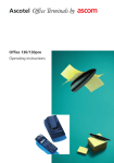
User Manual PPC-L62T Intel Atom Processor-Based Panel PC with 6.5” Color TFT LCD Display Copyright The documentation and the software included with this product are copyrighted 2012 by Advantech Co., Ltd. All rights are reserved. Advantech Co., Ltd. reserves the right to make improvements in the products described in this manual at any time without notice. No part of this manual may be reproduced, copied, translated or transmitted in any form or by any means without the prior written permission of Advantech Co., Ltd. Information provided in this manual is intended to be accurate and reliable. However, Advantech Co., Ltd. assumes no responsibility for its use, nor for any infringements of the rights of third parties, which may result from its use. Acknowledgements Intel and Pentium are trademarks of Intel Corporation. Microsoft Windows and MS-DOS are registered trademarks of Microsoft Corp. All other product names or trademarks are properties of their respective owners. Product Warranty (2 years) Advantech warrants to you, the original purchaser, that each of its products will be free from defects in materials and workmanship for two years from the date of purchase. This warranty does not apply to any products which have been repaired or altered by persons other than repair personnel authorized by Advantech, or which have been subject to misuse, abuse, accident or improper installation. Advantech assumes no liability under the terms of this warranty as a consequence of such events. Because of Advantech’s high quality-control standards and rigorous testing, most of our customers never need to use our repair service. If an Advantech product is defective, it will be repaired or replaced at no charge during the warranty period. For outof-warranty repairs, you will be billed according to the cost of replacement materials, service time and freight. Please consult your dealer for more details. If you think you have a defective product, follow these steps: 1. Collect all the information about the problem encountered. (For example, CPU speed, Advantech products used, other hardware and software used, etc.) Note anything abnormal and list any onscreen messages you get when the problem occurs. 2. Call your dealer and describe the problem. Please have your manual, product, and any helpful information readily available. 3. If your product is diagnosed as defective, obtain an RMA (return merchandise authorization) number from your dealer. This allows us to process your return more quickly. 4. Carefully pack the defective product, a fully-completed Repair and Replacement Order Card and a photocopy proof of purchase date (such as your sales receipt) in a shippable container. A product returned without proof of the purchase date is not eligible for warranty service. 5. Write the RMA number visibly on the outside of the package and ship it prepaid to your dealer. PPC-L62T User Manual Part No. 200KL62T10 Edition 1 Printed in China February 2012 ii Declaration of Conformity CE This product has passed the CE test for environmental specifications when shielded cables are used for external wiring. We recommend the use of shielded cables. This kind of cable is available from Advantech. Please contact your local supplier for ordering information. CE This product has passed the CE test for environmental specifications. Test conditions for passing included the equipment being operated within an industrial enclosure. In order to protect the product from being damaged by ESD (Electrostatic Discharge) and EMI leakage, we strongly recommend the use of CE-compliant industrial enclosure products. FCC Class B Note: This equipment has been tested and found to comply with the limits for a Class B digital device, pursuant to part 15 of the FCC Rules. These limits are designed to provide reasonable protection against harmful interference when the equipment is operated in a commercial environment. This equipment generates, uses, and can radiate radio frequency energy and, if not installed and used in accordance with the instruction manual, may cause harmful interference to radio communications. Operation of this equipment in a residential area is likely to cause harmful interference in which case the user will be required to correct the interference at his own expense. Technical Support and Assistance 1. 2. Visit the Advantech web site at www.advantech.com/support where you can find the latest information about the product. Contact your distributor, sales representative, or Advantech's customer service center for technical support if you need additional assistance. Please have the following information ready before you call: – Product name and serial number – Description of your peripheral attachments – Description of your software (operating system, version, application software, etc.) – A complete description of the problem – The exact wording of any error messages iii PPC-L62T User Manual Safety Instructions 1. 2. 3. Read these safety instructions carefully. Keep this User Manual for later reference. Disconnect this equipment from any DC outlet before cleaning. Use a damp cloth. Do not use liquid or spray detergents for cleaning. 4. For plug-in equipment, the power outlet socket must be located near the equipment and must be easily accessible. 5. Keep this equipment away from humidity. 6. Put this equipment on a reliable surface during installation. Dropping it or letting it fall may cause damage. 7. The openings on the enclosure are for air convection. Protect the equipment from overheating. DO NOT COVER THE OPENINGS. 8. Make sure the voltage of the power source is correct before connecting the equipment to the power outlet. 9. Position the power cord so that people cannot step on it. Do not place anything over the power cord. 10. All cautions and warnings on the equipment should be noted. 11. If the equipment is not used for a long time, disconnect it from the power source to avoid damage by transient overvoltage. 12. Never pour any liquid into an opening. This may cause fire or electrical shock. 13. Never open the equipment. For safety reasons, the equipment should be opened only by qualified service personnel. 14. If one of the following situations arises, get the equipment checked by service personnel: 15. The power cord or plug is damaged. 16. Liquid has penetrated into the equipment. 17. The equipment has been exposed to moisture. 18. The equipment does not work well, or you cannot get it to work according to the user's manual. 19. The equipment has been dropped and damaged. 20. The equipment has obvious signs of breakage. 21. DO NOT LEAVE THIS EQUIPMENT IN AN ENVIRONMENT WHERE THE STORAGE TEMPERATURE MAY GO BELOW 0° C (32° F) OR ABOVE 50° C (122° F). THIS COULD DAMAGE THE EQUIPMENT. THE EQUIPMENT SHOULD BE IN A CONTROLLED ENVIRONMENT. 22. CAUTION: DANGER OF EXPLOSION IF BATTERY IS INCORRECTLY REPLACED. REPLACE ONLY WITH THE SAME OR EQUIVALENT TYPE RECOMMENDED BY THE MANUFACTURER, DISCARD USED BATTERIES ACCORDING TO THE MANUFACTURER'S INSTRUCTIONS. 23. The sound pressure level at the operator's position according to IEC 704-1:1982 is no more than 70 dB (A). DISCLAIMER: This set of instructions is given according to IEC 704-1. Advantech disclaims all responsibility for the accuracy of any statements contained herein. PPC-L62T User Manual iv Safety Precaution - Static Electricity Follow these simple precautions to protect yourself from harm and the products from damage. To avoid electrical shock, always disconnect the power from your PC chassis before you work on it. Don't touch any components on the CPU card or other cards while the PC is on. Disconnect power before making any configuration changes. The sudden rush of power as you connect a jumper or install a card may damage sensitive electronic components. v PPC-L62T User Manual PPC-L62T User Manual vi Contents Chapter 1 General Information ............................1 1.1 1.2 Introduction ............................................................................................... 2 Specifications ............................................................................................ 2 1.2.1 General Specifications .................................................................. 2 1.2.2 Standard PC Functions................................................................. 2 1.2.3 Internal Graphics Specifications ................................................... 2 1.2.4 Audio Functions ............................................................................ 2 1.2.5 Ethernet Interface ......................................................................... 2 1.2.6 Touchscreen Specifications (Optional) ......................................... 3 Table 1.1: Touchscreen Specifications........................................ 3 1.2.7 Optional Modules .......................................................................... 3 1.2.8 Environment.................................................................................. 3 1.2.9 Certifications: ................................................................................ 3 Dimensions ............................................................................................... 4 Figure 1.1 Dimensions of PPC-L62T ........................................... 4 1.3 Chapter 2 System Setup .......................................5 2.1 A Quick Tour of the Panel PC ................................................................... 6 Figure 2.1 Front Panel of PPC-L62T ........................................... 6 Figure 2.2 Side View of the Panel PC ......................................... 6 Figure 2.3 I/O Peripheral Connectors Panel of DC Input Model.. 7 Figure 2.4 I/O Peripheral Connectors Panel of DC Input Model.. 7 Figure 2.5 Rear View of the Panel PC......................................... 8 Preparing for First-time Use ...................................................................... 8 Installation Procedures.............................................................................. 8 2.3.1 Connecting the Power Cord.......................................................... 8 2.3.2 Connecting the Keyboard and Mouse........................................... 8 2.3.3 Switching on the Power ................................................................ 9 Running the BIOS Setup Program ............................................................ 9 Installing System Software........................................................................ 9 Installing the Drivers.................................................................................. 9 Figure 2.6 Drivers and Utilities on the CD-ROM.......................... 9 2.2 2.3 2.4 2.5 2.6 Chapter Chapter 3 Using the Panel PC............................11 3.1 3.2 3.3 3.4 3.5 3.6 Introduction ............................................................................................. 12 Serial COM Ports .................................................................................... 12 Figure 3.1 I/O Ports ................................................................... 12 USB Ports ............................................................................................... 13 Audio Interface ........................................................................................ 13 Ethernet................................................................................................... 13 Touchscreen (Optional)........................................................................... 13 4 Hardware Installation ........................15 4.1 4.2 Introduction ............................................................................................. 16 Disassembling the Panel PC................................................................... 16 Figure 4.1 Unfastening the Rear Cover ..................................... 16 Installing the 2.5" Hard Disk Drive........................................................... 17 Figure 4.2 Unfastening the Rear Cover ..................................... 17 Figure 4.3 SATA HDD Cable & HDD Rear Cover Connected to the 4.3 vii PPC-L62T User Manual 4.4 4.5 Chapter HDD.......................................................................... 17 Figure 4.4 Assembly HDD Module to Rear Cover..................... 18 Figure 4.5 HDD Module is Mounted to the Machine.................. 18 Installing the DDR3 SDRAM Memory Module ........................................ 19 Figure 4.6 Placing the memory card on the board end ............. 19 Installing Wireless Network Card ............................................................ 20 Figure 4.7 Out of box on the left side of the rubber plug ........... 20 Figure 4.8 Install the wireless LAN card and antenna ............... 20 5 Jumpers and Connectors................. 21 5.1 Jumpers and Connectors........................................................................ 22 5.1.1 Setting Jumpers.......................................................................... 22 5.1.2 Jumpers ...................................................................................... 23 Table 5.1: Jumpers List ............................................................. 23 Table 5.2: JP1: CMOS CLEAR & AT / ATX Select ................... 23 Table 5.3: CN16: Ring and Power for COM1 pin 9 ................... 23 5.1.3 Jumper and Connector Locations............................................... 24 Figure 5.1 Jumpers & Connectors on PPC-L62T Motherboard. 24 5.1.4 Connectors ................................................................................. 25 Table 5.4: Connectors List ........................................................ 25 Table 5.5: CN23: DC IN ............................................................ 25 Table 5.6: CN24/25/26: COM1/2/3............................................ 26 PPC-L62T User Manual viii Chapter 1 1 General Information This chapter gives background information on the PPC-L62T. Sections include: Specifications Dimensions 1.1 Introduction Advantech PPC-L62T is an Intel Atom processor based Panel PC with a bright 6.5" LCD display. The powerful Atom CPU and Intel ICH8M chipsets bring the most dynamic applications to life without sacrifices to any industrial reliability. The Internal CFast card interface can serve as an alternate HDD solution for OS booting and the Mini PCIe interface can be used a wireless LAN card to extend device mobility. In order to satisfy customers’ security concerns, PPC-L62T-R80-AXE is also offered in a two Gigabit LAN port configuration. Two serial ports and four USB V2.0 ports give the PPC-L62T-R80-AXE advanced application capability. And PPC-L62T-R80-BXE is also offered in a one Gigabit LAN port configuration.Three serial ports and two USB V2.0 ports give the PPC-L62T-R80-BXE advanced application capability. 1.2 Specifications 1.2.1 General Specifications Dimensions (W X H X D): 202 x 148 x 49 mm Weight: 1.2 kg (13.22 lb) Power: – Input voltage 15 ~ 24 V 1.2.2 Standard PC Functions CPU: Support Intel® N455 processor up to 1.66GHz BIOS: Award 8 MB Flash BIOS, supports plug and play, ACPI (advanced configuration and power interface) Chipset: Intel® ICH8-M RAM: One 204-pin sockets up to 2 GB DDR3 SO-DIMMs Serial ports: Two serial ports, – PPC-L62T-R80-AXE: COM1:RS-232, COM2:RS-232/422/485 – PPC-L62T-R80-BXE: COM1/3:RS-232, COM2:RS232/422/485 Universal serial bus (USB) port: – PPC-L62T-R80-AXE: Supports up to four USB V2.0 ports – PPC-L62T-R80-BXE: Supports up to two USB V2.0 ports 1.2.3 Internal Graphics Specifications Intel Dynamic Video Memory Technology 4.0 200 MHz render clock frequency VGA (Option) Intel® Clear Video Technology (MPEG2 Hardware Acceleration, ProcAmp) 1.2.4 Audio Functions Chipset: Realtek ALC892 Audio controller: Supports host/soft audio from the Intel ICH series chipset Stereo sound: Two stereo ADCs support 16/20/24-bit PCM format 1.2.5 Ethernet Interface 802.3x flow control support compliant IEEE 802.1p and 802.1q support 10/100/1000 IEEE 802.3 compliant PPC-L62T User Manual 2 Chapter 1 1.2.6 Touchscreen Specifications (Optional) Table 1.1: Touchscreen Specifications Type Analog Resistive 640 x 480 Light Transmission 81% Controller COM/USB Software Driver Windows Durability (touches in a life- time) 36 million 1.2.7 Optional Modules CPU: Supports Intel Atom processor, single-core N455 1.66 GHz Memory: Supports up to 2 GB DDR3 SO-DIMMs [204-pin SODIMM socket] HDD: Supports 2.5" SATA HDD Touchscreen: Analog resistive CFast: 1 CFast slot 1.2.8 Environment Temperature: 0 ~ 50° C (32 ~ 122° F) Relative humidity: 10 ~ 95% @ 40° C (non-condensing) Shock: 10 G peak acceleration (11 msec duration) 1.2.9 Certifications: EMC: CE, FCC, BSMI, CCC Safety: CB, UL, BSMI, CCC 3 PPC-L62T User Manual General Information Resolution 1.3 Dimensions Figure 1.1 Dimensions of PPC-L62T PPC-L62T User Manual 4 Chapter 2 2 System Setup This chapter gives system setup information for the PPC-L62T. Sections include: A Quick Tour Installation Procedures Running the BIOS Setup Installing System software 2.1 A Quick Tour of the Panel PC Before starting to set up the panel PC, take a moment to become familiar with the locations and purposes of controls, drives, connectors and ports, which are illustrated in the figures below. When placed upright on the desktop, the front panel of the panel PC appears as shown in Figure 2.1. Figure 2.1 Front Panel of PPC-L62T When viewed from the left side of the panel PC, the CFast, holes for panel mount are visible, as shown in Figure 2.2. &)DVW +ROHVIRUSDQHOPRXQW Figure 2.2 Side View of the Panel PC PPC-L62T User Manual 6 PPC-L62T-R80-AXE $ % & ' ( ) * A: DC Inlet C: Line Out E: 10/100 /1000 Mbps Ethernet x 2 G: RS-232/422/485 x 1 B: RS-232x 1 D: USB 2.0 x 2 F: USB 2.0 x 2 PPC-L62T-R80-BXE $ % & ' ( ) * Figure 2.4 I/O Peripheral Connectors Panel of DC Input Model A: DC Inlet C: Line Out E: 10/100/1000 Mbps Ethernet x 1 G: RS-232/422/485 x 1 B: RS-232 x 1 D: USB 2.0 x 2 F: RS-232 x 1 7 PPC-L62T User Manual System Setup Figure 2.3 I/O Peripheral Connectors Panel of DC Input Model Chapter 2 Viewed from the side. (The I/O section includes various I/O ports, including serial ports, USB ports, the Ethernet ports and so on. VESA standard: 75 x 75 mm mounting size. Figure 2.5 Rear View of the Panel PC Caution! Use recommended mounting apparatus to avoid risk of injury. 2.2 Preparing for First-time Use Before commencing set up of the panel PC system, the following items should be available: Keyboard Mouse (for system software installation) 2.3 Installation Procedures 2.3.1 Connecting the Power Cord The panel PC can be powered through an DC outlet (15 ~ 24 V). Be sure to handle the power cords by holding the plug ends only. Follow these procedures in order: 1. Connect the female end of the power cord to the DC inlet of the panel PC. 2. Connect the 3-pin male plug of the power cord to an electrical outlet. 2.3.2 Connecting the Keyboard and Mouse Connect the mouse and keyboard to the I/O section of PPC. If using a serial mouse and the panel PC has a touchscreen, it is possible to connect the mouse to any COM port. PPC-L62T User Manual 8 Switch on the power switch, which is located inside the back cover. 2.4 Running the BIOS Setup Program 2.5 Installing System Software Recent releases of operating systems from major vendors include setup programs which load automatically and guide you through hard disk formatting and operating system installation. The guidelines below will help determine the steps necessary to install the operating system onto the panel PC hard drive. Note! Some distributors and system integrators may have already preinstalled system software prior to shipment. 2.6 Installing the Drivers After installing your system software, you will be able to set up the Chipset, Ethernet, VGA, audio and touchscreen functions. All the drivers are stored in a CD-ROM disc labeled "Drivers and Utilities”. The CD-ROM can be found in your accessory box. Figure 2.6 Drivers and Utilities on the CD-ROM Note! The drivers and utilities used for the PPC-L62T panel PCs are subject to change without notice. If in doubt, check Advantech's website or contact our application engineers for the latest information regarding drivers utilities. 9 PPC-L62T User Manual System Setup The panel PC will be properly set up and configured by the dealer prior to delivery. However, it may be necessary to use the panel PC's BIOS (Basic Input-Output System) setup program to change the system configuration information, such as the current date and time, or the type of hard drive. The setup program is stored in read-only memory (ROM). It can be accessed either when you turn on or reset the panel PC, by pressing the ‘Del’ key on your keyboard immediately after powering on the computer. The settings specified with the setup program are recorded in a special area of memory called “CMOS RAM”. This memory is backed up by a battery so that it will not be erased after turning off or resetting the system. Whenever the power is turned on, the system reads the settings stored in CMOS RAM and compares them to the equipment check conducted during the power on self-test (POST). If a problem occurs, an error message will be displayed on screen, and the computer prompts the user to run the setup program. Chapter 2 2.3.3 Switching on the Power PPC-L62T User Manual 10 Chapter 3 3 Using the Panel PC This chapter explains onboard devices and peripheral I/O ports available on the PPC-L62T. Sections include: Serial COM Ports USB Ports Audio Interface Ethernet Touchscreen (Optional) 3.1 Introduction This chapter describes basic features and procedures for using the panel PC. Topics covered include: I/O ports and the touchscreen. This product is a high performance panel PC, please keep upright. 3.2 Serial COM Ports There are four serial COM ports on the side. It is simple to attach a serial device to the panel PC, such as an external modem or mouse. Follow these instructions: 1. Be sure the panel PC and any other peripheral devices that are connected to the panel PC are turned off. 2. Attach the interface cable of the serial device to the panel PC's serial port. If necessary, attach the other end of the interface cable to the serial device. Fasten any retaining screws. 3. Turn on any other peripheral devices which are connected to the panel PC, and then turn on the panel PC. 4. Refer to the manual(s) which accompanied any serial device(s) for instructions on configuring the operating environment to recognize the device(s). 5. Run the BIOS setup program and configure the jumper settings to change the mode of the COM ports. Figure 3.1 I/O Ports PPC-L62T User Manual 12 An external USB device may be connected to the system through the USB ports located on the rear side and left side of the system unit. 1. Connect the external device to the system. 2. The USB ports support hot plug-in connections. Install the device driver before using the device. The audio interface includes one jack to line out. Their functions are: Line out: Output audio to external devices such as speakers or earphones. 1. Connect the audio device to the system. 2. Install the driver before using the device. 3.5 Ethernet External devices on the network may be connected to the system through the external Ethernet port located on the bottom of the system unit. 3.6 Touchscreen (Optional) The touchscreen is connected to the internal COM port. Its function is similar to that of a mouse. PPC-L62T supports resistive touchscreen. It is necessary to install the touchscreen driver before it will function. The touchscreen drivers for various operating systems are stored on the CD-ROM disc inside the accessory box. 13 PPC-L62T User Manual Using the Panel PC 3.4 Audio Interface Chapter 3 3.3 USB Ports PPC-L62T User Manual 14 Chapter 4 4 Hardware Installation This chapter gives instructions for installing hardware devices on the PPC-L62T. Sections include: Introduction Disassembling the Panel PC Installing HDD Module Installing Memory Module Installing Wireless Network Card 4.1 Introduction The panel PC consists of a PC-based computer that is housed in a metal shielding case with a rear cover on the rear and bottom. All the computer devices, like the CPU, SDRAM and power supply are all readily accessible after removing the rear panel or the HDD cover. Any maintenance or hardware upgrades can be easily completed after removing the rear panel and/or HDD cover. Warning! Do not remove the rear cover until verifying that no power is flow-ing within the panel PC. Power must be switched off and the power cord must be unplugged. Each time the panel PC is serviced, users should be aware of this condition. 4.2 Disassembling the Panel PC The following are standard procedures for disassembling the panel PC before upgrading the system. All procedures are illustrated in Figure 4.1. 1. Unfasten the screws securing the rear cover and remove it. Figure 4.1 Unfastening the Rear Cover PPC-L62T User Manual 16 One serial ATA (SATA) hard disk drive may be attached to the panel PC. The following instructions are for installing the HDD: 1. Remove the six screws on rear cover first. (See Figure 4.2) 2. Place SATA HDD Cable & HDD rear cover connected to the HDD. (See Figure 4.3) Figure 4.3 SATA HDD Cable & HDD Rear Cover Connected to the HDD 17 PPC-L62T User Manual Hardware Installation Figure 4.2 Unfastening the Rear Cover Chapter 4 4.3 Installing the 2.5" Hard Disk Drive 3. The HDD module is mounted to the cover& the machine. (See Figure 4.4) Figure 4.4 Assembly HDD Module to Rear Cover 4. Tighten rear cover 6 screws, the HDD module is mounted to the machine. (See Figure 4.5) Figure 4.5 HDD Module is Mounted to the Machine PPC-L62T User Manual 18 The panel PC system provides one 204-pin SODIMM sockets and it is able to install 2 GB of DDR3 SDRAM memory. The following instructions are for installing the DDR3 SDRAM Memory: 1. Placing the memory card on the board end corresponding position. (See Figure 4.6) Chapter 4 4.4 Installing the DDR3 SDRAM Memory Module Hardware Installation Figure 4.6 Placing the memory card on the board end 19 PPC-L62T User Manual 4.5 Installing Wireless Network Card The following instructions are for installing the wireless network card: 1. Remove the rubber plug (out of box on the top side). (See Figure 4.7) Figure 4.7 Out of box on the left side of the rubber plug 2. Install the wireless LAN card and antenna. (See Figure 4.8) Figure 4.8 Install the wireless LAN card and antenna PPC-L62T User Manual 20 Chapter 5 5 Jumpers and Connectors This chapter gives information on setting jumpers and using the connectors on the PPC-L62T motherboard. Sections include: Setting Jumpers Jumpers Jumpers and Connectors Locations Connectors 5.1 Jumpers and Connectors This chapter supplies more detailed information about the internal jumper settings and an outline of the I/O ports available on the PPC-L62T. 5.1.1 Setting Jumpers The Panel PC can be configured to match the needs of each application by setting jumpers. A jumper is the simplest kind of electrical switch. It consists of two metal pins and a small metal clip (often protected by a plastic cover), which slides over the pins to close the circuit and connect them. To ”close” a jumper, connect the pins with the clip. To “open” a jumper, remove the clip. Sometimes a jumper has three pins, labeled 1, 2, and 3. In this case, it is possible to connect either pins 1 and 2 or pins 2 and 3 to each other. Open Closed Closed 2-3 The jumper settings are schematically depicted in this manual as follows: 1 Open Closed 2 3 Closed 2-3 A pair of needle-nose pliers may be helpful when working with jumpers. If there are any doubts about the best hardware configuration for a particular application, contact the local distributor or sales representative before making any changes. An arrow is printed on the motherboard to indicate the first pin of each jumper. PPC-L62T User Manual 22 The motherboard of the panel PC has a number of jumpers that help configure the system. It also has LED indicator lights that display the system operation status. The table below lists the function of each jumper and LED. The motherboard of the PPC-L62T has a number of jumpers that allow you to configure your system to suit your applications. Chapter 5 5.1.2 Jumpers Table 5.1: Jumpers List CMOS CLEAR & AT/ATX Select CN16 Ring and Power for COM1/ pin 9 Jumpers and Connectors JP1 Table 5.2: JP1: CMOS CLEAR & AT / ATX Select Setting Function (1-3) CMOS Clear (3-5) Normal (default) (2-4) AT Power (4-6) ATX Power (default) Table 5.3: CN16: Ring and Power for COM1 pin 9 Setting Function (1-2) COM1_Pin9 RI (default) (2-3)/(3-4) COM1_Pin9 +V5 (4-5) COM1_Pin9 +V12 23 PPC-L62T User Manual 5.1.3 Jumper and Connector Locations CN1 CN3 JP1 CN4 CN5 CN7 CN8 CN6 CN9 CN12 CN13 CN11 CN16 CN14 CN15 CN17 CN24 CN25 CN20 CN19/18 CN21 CN22 CN26 CN23 CN27 Figure 5.1 Jumpers & Connectors on PPC-L62T Motherboard PPC-L62T User Manual 24 Onboard connectors link the panel PC to external devices such as hard disk drives. The table below lists the function of each of connectors. Table 5.4: Connectors List Function CN1 LVDS Back Light CN3 LVDS CN4 LPC Connect CN5 GPIO CN6 MiniPCIE CN8 T/S Connect CN9 VGA Connect CN11 DIMM CN12 SATA CN13 SATA Powe CN14 USB 0/1 CN15 Button CN17 Speak CN18 LAN2 CN19 LAN1 CN20 USB 6/7 CN21 USB 8/9 CN22 LIN OUT CN23 DC IN CN24 COM 2 CN25 COM 3 (Reserve) CN26 COM 1 CN27 CFAST Jumpers and Connectors Label Table 5.5: CN23: DC IN Pin Pin Name 1 DC_IN 2 GND Chapter 5 5.1.4 Connectors 25 PPC-L62T User Manual Table 5.6: CN24/25/26: COM1/2/3 Pin Pin Name 1 DCD# 2 RX 3 TX 4 DTR# 5 GND 6 DSR# 7 RTS# 8 CTS# 9 RI# PPC-L62T User Manual 26 www.advantech.com Please verify specifications before quoting. This guide is intended for reference purposes only. All product specifications are subject to change without notice. No part of this publication may be reproduced in any form or by any means, electronic, photocopying, recording or otherwise, without prior written permission of the publisher. All brand and product names are trademarks or registered trademarks of their respective companies. © Advantech Co., Ltd. 2012 XXX-XXXX User Manual 28