1
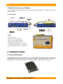
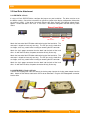
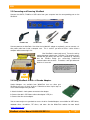
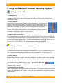
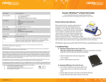
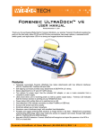
UltraDock™ v4
USER MANUAL
Revised August 2, 2011
Features
• Quadruple connectivity! UltraDock is compatible with four different interfaces: eSATA, FireWire 800,
FireWire 400 and USB.
• Self-aligning connector provides easy attachment of IDE/PATA 3.5” drives
• Host attachment for 2.5” and 3.5” SATA drives.
• LEDs show when unit is receiving power as well as power output status
• Power status LED verifies that unit is switched on (or off)
• Host-detection LEDs indicate connection to either FireWire or USB host
• Access LED shows hard drive activity
• Small size allows you to take it anywhere
• Aluminum case is briefcase tough, with excellent heat dissipation
• Two options for power input: Use the included AC adapter, or use a 4-wire connector from a
computer’s power supply
UltraDock v4 User Manual A9-000-0026 REV 1.0
-1-
CRU
Table of Contents
1. Pre-Installation Steps
2
1.1 UltraDock v4 Accessories
1.2 Identifying Parts
2
3
2. Installation Steps
3
2.1 Attach a Bottom Plate
2.2 Hard Drive Attachment
4
5
5
2.2.1 IDE/PATA: 3.5-inch
2.2.2 SATA HDD: 3.5-inch & 2.5-inch
5
2.3 Connecting and Powering UltraDock
2.4 Using UltraDock v4 with WiebeTech’s v4 Combo Adapters
5
3. Usage with Mac and Windows Operating Systems
6
3.1 Usage with Macintosh Computers
6
5
3.1.1 Compatibility
3.1.2 Using Volumes
3.1.3 Booting from your UltraDock
6
6
6
3.2 Usage with Windows Operating System
6
3.2.1 Compatibility
3.2.2 Using Volumes
3.2.3 Booting from your UltraDock
6
6
7
4. Frequently Asked Questions
5. Technical Specifications
7
8
1. Pre-Installation Steps
1.1 Check the accessories packaged with your UltraDock.
The following list contains the items included in the complete configuration for this device. Depending on
which configuration and accessories you purchased, the package may include fewer items than what are
listed here. Please contact CRU-DataPort if any items are missing or damaged:
UltraDock
AC adapter & power cord
FireWire 800 cable
FireWire 400 cable
USB cable
eSATA cable
SATA power/data cable
Metal bottom plate
Hard drive screws
Rubber bumpers
Quick Start Guide and Warranty information
UltraDock v4 User Manual A9-000-0026 REV 1.0
1
1
1
1
1
1
1
1
4
4
1
-2-
CRU
1.2 Identify the Parts of your UltraDock
Take a moment to familiarize yourself with the parts of your new UltraDock. This will aid you in the
remaining steps.
1.2.3 Connectors
LEDs
a Hard drive access
b Unit is connected to USB host
c Unit is connected to FireWire host
d +12V DC power input is present
e Optional 4-pin power input is connected
f +12V Power output to drive is on (yellow wire)
g +5V Power output to drive is on (red wire)
2. Installation Steps
2.1 Attach a Bottom Plate
Attach bottom plate to your 3.5-inch hard drive. This step is optional but recommended. The purpose of
the bottom plate is to provide protection to your drive electronics and aid heat dissipation. Attach the
bottom plate to your drive using the four screws supplied. Attach a rubber bumper to each corner.
UltraDock v4 User Manual A9-000-0026 REV 1.0
-3-
CRU
2.2 Hard Drive Attachment
2.2.1 IDE/PATA: 3.5-inch
If using a 3.5-inch IDE/PATA drive, configure the jumpers on your hard drive. The drive must be set to
the Master setting. Consult the instructions for your drive (some drives display configuration information
on the drive’s label). A few drives have both “Master with Slave Present” and “Master without Slave”
options. Choose the latter in this case. In rare cases, if the Master setting does not work then try Cable
Select.
Rear of hard drive
(Example)
IDE interface
Jumper
Pins
Power
Attach the free end of the IDE ribbon cable to the back of the hard drive. The
connector is keyed to insert only one way. The IDE pins on the hard drive
are fragile, so be very careful when inserting or removing the IDE connector
Attach the 4-pin power connector from the dock into the back of the hard
drive. As with the IDE cable, the power connector will only fit one way.
2.2.2 SATA HDD: 3.5-inch & 2.5-inch
Take the SATA power/data cable and attach the 4-wire power input to the 4-wire power output from the
dock. Attach the SATA data cable to the SATA slot on UltraDock. Plug the SATA data/power connector
into the drive.
UltraDock v4 User Manual A9-000-0026 REV 1.0
-4-
CRU
2.3 Connecting and Powering UltraDock
Connect the eSATA, FireWire or USB cable from your computer into the corresponding port on the
UltraDock.
FireWire 400
FireWire 800
USB
eSATA
Connect power to the UltraDock. Use either the included AC adapter or, optionally, you can connect a 4wire power cable from inside a computer case. This is useful if you wish to access a drive inside a
computer without removing it first.
Your UltraDock is now ready to use! Turn on the unit by
moving the power switch to the “I” position. The red drive access
indicator will light briefly after the unit is powered up, indicating
that the FireWire bridge has successfully established
communication with the drive. Thereafter, it will light whenever
the drive is accessed.
Note: The UltraDock may utilize any 12V
regulated switching power supply capable of
supplying 2A or greater. Do not use
unregulated adapters, as damage may occur to
the UltraDock or the attached drive.
2.4 Using UltraDock v4 with v4 Combo Adapters
Combo Adapters are available from WiebeTech that can allow your
UltraDock to access all kinds of drives. Follow these three simple steps to
use a Combo Adapter with your dock:
1. Attach the dock’s 4-wire power connector to the adapter.
2. Connect the dock’s IDE ribbon cable to the adapter’s IDE pins.
3. Connect the drive to the adapter.
You are now ready to use your dock to access the drive. Combo Adapters are available for SATA drives,
notebook drives, microdrives, ZIF drives, and more. See the WiebeTech website for more details
(www.wiebetech.com).
UltraDock v4 User Manual A9-000-0026 REV 1.0
-5-
CRU
3. Usage with Mac and Windows Operating Systems
3.1 Usage with Mac OS X
3.1.1 Compatibility
UltraDock does not require drivers for operation under Mac OS X. However, if you install a host card
specifically to work with this product, that card may require drivers. See your card’s User Manual for
drivers and instructions.
3.1.2 Using Volumes
If the hard drive attached to the UltraDock is already formatted, an icon representing
the drive’s volume will appear (mount) on the desktop. You can begin using the volume
right away. If the drive is unformatted, a message will appear on the desktop saying
that the disk is unreadable. You can use OS X’s Disk Utility to easily format the drive.
Eject the volume before powering down the unit by dragging the volume’s icon to the
trash bin, or by selecting the volume then pressing Command-E. Shutting down the
unit without first ejecting the volume can result in data loss.
3.1.3 Booting from your UltraDock
Some Macs support booting from an external device. To activate this feature, you must first install OS X
on the external volume. The easiest way to do this is to clone an existing system drive using a utility such
as Carbon Copy Cloner or Super Duper. Next, go to System Preferences Startup Disk. A window will
list the available bootable volumes. Select the volume from which you wish to boot. Another method is to
hold down the Option key during boot up. A screen should appear that allows you to select the volume
you wish to use. This is useful if you wish to boot from your dock only some of the time.
3.2 Usage with Windows operating systems
3.2.1 Compatibility
UltraDock does not require drivers for operation under Windows XP, Vista, or 7. However, if you install a
host card specifically to work with this product, that card may require drivers. See your card’s User
Manual for drivers and instructions.
3.2.2 Using Volumes
If the hard drive attached to the dock is already formatted, you can begin using the volume right away.
When the dock and drive are properly connected and turned on, a window may open to allow you access
to the volume. If no window appears, you can find the volume by double-clicking the “My Computer” icon.
Eject the volume before powering down the unit by single-clicking the green arrow
icon on the task bar, then selecting “Safely remove….” Windows will indicate when
it is safe to disconnect the dock. Shutting down the unit without first ejecting the
volume can result in data loss.
(Windows XP)
3.2.3 Booting from your UltraDock
Some PC motherboards support booting from an external device. To activate this feature, you will need
to adjust the motherboard’s BIOS settings. Check with your motherboard’s manufacturer or owner’s
manual for details.
UltraDock v4 User Manual A9-000-0026 REV 1.0
-6-
CRU
4. Frequently Asked Questions
Q: My UltraDock v4 works great with SATA drives but I am having compatibility issues with IDE/PATA
drives. What should I do?
A: First check to make sure the SATA power/data cable is unplugged from the SATA output port.
IDE/PATA drives cannot be recognized if a SATA connection is made with the SATA output. Next check
to make sure the 4-pin power cable is plugged into the IDE/PATA drive. If the power and host connection
are securely attached to the UltraDock v4, then the IDE cable may be faulty. Contact Technical Support
for further instructions.
Q: Why does my dock experience errors or unmount during long file transfers?
A: The environment in which the dock is used can affect its performance. The surface that the dock and
drive are set upon may not allow heat to dissipate away from the units. The bottom plate supplied with the
product will help to dissipate heat away from the hard drive and dock. If placed on a non-conductive
surface, the drive or dock may suffer heat related failures. After cooling, the units usually return to a
useable state. Occasionally these heat related failures can be permanent.
Q: How should I set my hard drive jumper settings?
A: Note: This is only necessary for IDE/PATA drives (the type of drive that has a 40-pin data interface).
Try the MASTER setting first. This is the recommended setting for most WiebeTech products. Some hard
drives have two different MASTER settings: one for when there is a SLAVE drive present and one for
when there is NO SLAVE drive present. Choose the setting for NO SLAVE present. There may be some
drives that will not work with either of these settings. The next choice is CABLE SELECT. If this does not
work, try using NO jumpers. This may be the same as MASTER with NO SLAVE present.
If you're unsure how to change the jumper configuration, check the manual that came with your hard
drive, or the manufacturer's website. Some drives also have the information printed on the label.
Q: I lost my AC adapter. Where can I get a replacement?
A: The AC adapters for all current WiebeTech products (and most discontinued products) are available
for purchase on our website.
Third party AC adapters can also be used with WiebeTech products as long as they have REGULATED
POWER. Be sure to check with the manufacturer of the adapter for this specification. Also check to make
sure the volts and amps are correct for the product, as well as the pin configuration (for DIN connectors).
Q: Why does Disk Utility show S.M.A.R.T. information as "not supported" for my external drive? I know
the drive supports this technology.
A: Even if a drive is S.M.A.R.T. enabled, external FireWire enclosures cannot pass S.M.A.R.T.
information to the host because this information is lost when the data is translated from the IDE protocol
to FireWire.
Enclosures that connect via eSATA usually pass S.M.A.R.T. data unless the enclosure combines more
than one drive into a hardware RAID. However, the eSATA host in the computer may or may not support
S.M.A.R.T. Check the card manufacturer's website for this specification.
Q: Can I attach an eSATA drive enclosure to the SATA drive connection on UltraDock? Will this allow
me to access it via FireWire or USB on my computer as if it were a bare hard drive?
A: Yes. By using an eSATA to SATA convertor cable, you can connect an eSATA drive enclosure to the
output (device) side of the dock. You can then connect the input (host) side to a computer via any of the
connections. This should give you access to the drive without requiring its removal from its housing. If
you are using a Forensic UltraDock, writes to the drive will be write-blocked.
UltraDock v4 User Manual A9-000-0026 REV 1.0
-7-
CRU
5. Technical Specifications
Product Name
Drive Interfaces
Host Interfaces
Power Supply
Compatibility
Operating System
Shipping Weight
Dimensions
Compliance
Support
UltraDock v4
3.5-inch IDE/PATA
2.5-inch & 3.5-inch SATA
eSATA
FireWire 800 (two ports, daisy-chainable)
FireWire 400
USB 2.0
Input: 100-240VAC; Output: +12V
3.5-inch IDE/PATA, 3.5-inch SATA and 2.5-inch SATA drives
•
•
•
•
•
•
• Windows XP, Vista, Windows 7
• Mac OS X
• Linux distributions supporting FireWire
3 pounds, including accessories
110mm (L) x 75mm (W) x 22mm (H)
Dimensions are exclusive of attached plates, drives, and cables.
CE, FCC, RoHs, C-Tick
We don’t want anything to go wrong with your CRU-DataPort product. But
if it does, Tech Support is standing by and ready to help. Contact us
through cru-dataport.com. CRU also offers phone support at (800-260-9800).
WiebeTech is a brand of CRU.
UltraDock is a trademark of CRU Acquisitions Group, LLC. Other marks are the property of their respective owners.
© 2008, 2011 CRU Acquisitions Group, LLC. All rights reserved.
Limited Product Warranty
CRU-DataPort (CRU) warrants UltraDock to be free of significant defects in material and workmanship for a period of one year from
the original date of purchase. CRU’s warranty is nontransferable and is limited to the original purchaser.
Limitation of Liability
The warranties set forth in this agreement replace all other warranties. CRU expressly disclaims all other warranties, including but
not limited to, the implied warranties of merchantability and fitness for a particular purpose and non-infringement of third-party rights
with respect to the documentation and hardware. No CRU dealer, agent or employee is authorized to make any modification,
extension, or addition to this warranty. In no event will CRU or its suppliers be liable for any costs of procurement of substitute
products or services, lost profits, loss of information or data, computer malfunction, or any other special, indirect, consequential, or
incidental damages arising in any way out of the sale of, use of, or inability to use any CRU product or service, even if CRU has
been advised of the possibility of such damages. In no case shall CRU’s liability exceed the actual money paid for the products at
issue. CRU reserves the right to make modifications and additions to this product without notice or taking on additional liability.
FCC Compliance Statement: “This device complies with Part 15 of the FCC rules. Operation is subject to the following two
conditions: (1) This device may not cause harmful interference, and (2) this device must accept any interference received, including
interference that may cause undesired operation.”
This equipment has been tested and found to comply with the limits for a Class B digital device, pursuant to Part 15 of the FCC
Rules. These limits are designed to provide reasonable protection against harmful interference when the equipment is operated in a
home or commercial environment. This equipment generates, uses, and can radiate radio frequency energy and, if not installed and
used in accordance with the instruction manual, may cause harmful interference to radio communications.
In the event that you experience Radio Frequency Interference, you should take the following steps to resolve the problem:
1) Ensure that the case of your attached drive is grounded.
2) Use a data cable with RFI reducing ferrites on each end.
3) Use a power supply with an RFI reducing ferrite approximately 5 inches from the DC plug.
4) Reorient or relocate the receiving antenna.
Tested to comply
with FCC standards
FOR HOME OR OFFICE USE
UltraDock v4 User Manual A9-000-0026 REV 1.0
-8-