1
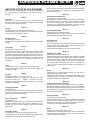
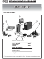
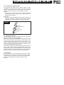
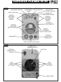
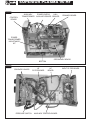
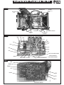
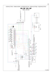
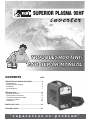
Cod.988343
SUPERIOR PLASMA 90HF
inver ter
TROUBLESHOOTING
AND REPAIR MANUAL
CONTENTS
PAGE
OPERATION AND WIRING DIAGRAMS.........................2
Block diagram
2
Analysis of block diagram
3
Illustrations
5
Wiring diagrams
7
REPAIR GUIDE..............................................................12
Equipment required
12
General repair instructions
13
Troubleshooting and remedies
13
Testing the machine
17
Illustrations
20
SPARE PARTS LIST...................................................... 24
REPAIRING CARD........................................................ 27
“reparation no-problem”
MAINS INPUT
INDUCTANCE
THERMOSTAT
43
35
34
36
E-
TORCH BUTTON
PROTECTION HF
25
27
3
RECTIFIER
BRIDGE
AUXILIARY
TRANSFORMER
FAN
24
33
23
22
DIODE
THERMOSTAT SEC.
UNDERVOLTAGE
SAFEGUARD
OVERVOLTAGE
SAFEGUARD
FASE FAILURE
2
VARISTOR
1
EMC FILTER
4
26
GENERAL ALARM
LED
PRE-CHARGE
19
27
AIR FAILURE
LED
MICROCONTROLLER
18
ALARM BLOCK
13
FLYBACK POWER
SUPPLY
5
FILTER
DRIVER
16
28
VOLTAGE OVER
TORCH LED
MAKER
DUTY CICLE
14
6
CHOPPER
17
15
29
POWER SUPPLY
LED
ADDER
CURRENT READER
AND LIMITER PR.
7
PR.CURRENT
CONTROL
8
30
FASE FAILURE
LED
41
ELECTROVALVE
TRANSFORMER
21
31
CURRENT POTENT.
39
10
INDUCTANCE
HALL SENSOR
20
+
-
32
E-
AIR BUTTON
42
HF GENERETOR
HF FILTER
PILOT ARC
ACTIVATION.
40
12
TRANSFORMER
11
SEC.EMC FILTER
33
37
ELECTROVALVE
SHUNT AMPLIFIER
HF PROTECTION
CURRENT MAX
REGULATOR
9
SEC. DIODES
AP
OUTPUT
SUPERIOR PLASMA 90 HF
OPERATION AND WIRING DIAGRAMS
BLOCK DIAGRAM
SUPERIOR PLASMA 90 HF
D3, D4 and D5 recirculate the inductance output current (block
9) while the IGBT's are not conducting, bypassing the power
transformer(block 8).
ANALYSIS OF THE BLOCK DIAGRAM
NOTE: Unless indicated otherwise, it should be assumed that
the components are assembled on the primary board or
machine.
Block 10
Inductance and Hall sensors
Consisting of: L1, Hall1 and Hall2
The inductance levels the output current from the secondary
board diodes making it practically direct. Hall1 sensor reads
the current of the pilot arc, Hall2 sensor reads the current
circulating in the inductance and sends it to block 20 (Hall
sensor amplifiers) which will process the information.
Block 1
EMC Filter
Consisting of: C1, C2, C3, C4, C5, C6, C7, L1 (input filter board)
Prevents noise from the machine from being transmitted along
the main power line and vice versa.
Block 2
Varistor
Consisting of: RV1, RV2, RV3 (input filter board)
Prevents spike noise from the mains, with amplitude greater
than 400V, from entering the machine.
Block 11
Secondary EMC Filter
Consisting of: C4, C5 (HF filter board)
Prevents noise from the power source from being transmitted
through the welding cables and vice versa.
Block 3
Rectifier bridge
Consisting of: D1, D2, D3
Converts the mains alternating voltage into continuous pulsed
voltage.
Block 12
HFTransformer
Consisting of:T2
The HF transformer boosts the signal from block 40 (hf power
source), raising the voltage impulse in the secondary at the
instant when arc strike is generated.
It also isolates the welding circuit from the primary circuit
Block 4
Pre-charge
Consisting of: K1, K2, K3, R1, R2
Prevents the formation of high transitory currents that could
damage the main power switch, the rectifier bridge and the
electrolytic capacitors. When the power source is switched on
relays K1, K2 and K3 are de-energised, capacitors C1, C2, C3,
C4, C1A, C2A, C3A C4A and C39 are then charged by R1 and
R2. When the capacitors are charged the relays will be
energised.
Block 13
Flyback power supply
Consisting of: U4, Q6, T3, U1, U2, U3
Uses switching methods to transform and stabilise the voltage
obtained from block 5 (filter) and supply 2 voltage values of
27V that enable block 14 (driver) to be powered correctly.The
auxiliary power supply board, on the other hand, generates
four further stabilised voltages (U2, U3, U4, U5) equal to a
+12V, +5V, -12V and 5V which are mainly used to power the
control board.
Block 5
Filter
Consisting of: C1, C2, C3, C4, C1A, C2A, C3A C4A, C39
Converts the pulsed voltage from the rectifier bridge into
continuous voltage.
Block 14
Driver
Consisting of: U1 (opto-insulators board), Q7, Q8 and U2
(opto-insulators board), Q9, Q10.
Takes the signal from block 13 (flyback power supply) and,
controlled by block 16 (duty cycle maker), makes the signal
suitable for piloting block 6 (chopper).
Block 6
Chopper
Consisting of: IGBT 1, 2, 3, 4, 5, 6, 7, 8, 9, 10
Converts the continuous voltage from the filter into a high
frequency square wav
capable of piloting the power
transformer. Regulates the power according to the required
welding current/voltage.
Block 15
Primary current reader and limiter
Consisting of: D3, R1, R2, R3 and R9 and R16 (control board)
Detects and limits the signal from block 7 (current transformer)
and sets the maximum allowed primary current. This signal is
also scaled down so that it can be processed and compared in
block 16 (duty cycle maker).
Block 7
Current transformer
Consisting of:TA
The C.T. is used to measure the current circulating in the power
transformer primary and transmit the information to block 14
(primary current reader and limiter).
Block 16
Duty cycle maker
Consisting of: U1(control board)
Processes the information from block 18 (adder) and block 15
(primary current reader and limiter) and produces a square
wave with variable duty cycle limiting the primary current to a
maximum pre-set value under all circumstances.
Block 8
Power transformer
Consisting of:T1
Adapts the voltage and current to the values required for the
welding procedure. Also forms galvanic separation of the
primary from the secondary (welding circuit from the power
supply line).
Block 17
Adder
Consisting of: U4A, U4B (control board)
Collects all the information arriving from block 21 (maximum
current control) and from block 19 (microcontroller), and sends
it to block 16 (duty cycle maker).
Block 9
Secondary diodes
Consisting of: D1, D2, D3, D4, D5 (secondary board)
D1 and D2 convert the current circulating in the transformer to
a single direction, preventing saturation of the core.
3
SUPERIOR PLASMA 90 HF
Block 18
Block 25
Alarm block
Consisting of: Q3, D12, D15 (control board)
When an alarm is detected, the block drastically limits machine
output current by acting directly on and changing the reference
signal obtained from block 16 (duty cycle maker), in the event
of:
1)Triggering of thermostatic capsule on secondary board
dissipator diodes.
2)Triggering of thermostatic capsule on power transformer.
3)Triggering due to undervoltage.
4) Triggering due to overvoltage.
5) Phase failure at input.
6) Short circuit at output (electrode holder clamp and earth
cable connected to each other or electrode stuck to piece
being welded).
Power transformer thermostat
Consisting of: thermostatic capsule ST2
When the temperature in the power transformer is too high this
safeguard triggers. It is reset automatically when the alarm
condition is no longer present.
Block 26
Red LED for general alarm
Consisting of: D2 (panel board)
Lights up following triggering of main supply overvoltage or
under voltage or of thermostatic capsules.
Block 27
Yellow LED for air failure
Consisting of: D7 (panel board)
Lights up simultaneously with red LED D37 if the air pressure is
insufficient or lacking.
Block 19
Microcontroller
Consisting of: U7 (control board).
Control logic, which manages typical timing for the plasma
cutting cycle. It also drastically limits power source output
current when it detects an alarm. In the event of an alarm it has
a direct effect on block 18 (alarm block), directly changing the
reference signal obtained from block 31 (current
potentiomenter).
Block 28
Yellow LED for torch voltage
Consisting of: D4 (panel board)
Lights up when the torch button is pressed, and shows the
cutting circuit is activated.
Block 29
Green LED for power supply
Consisting of: D5 (panel board)
Lights up when the machine is powered and shows the
machine is ready for operation.
Block 20
Hall sensor amplifiers
Consisting of:U3A, U3C, U4C, U4D and U5 (control board)
They amplify the signals arriving from block 10 (Hall sensors
inductance) and the Hall sensors (Hall1 and Hall2) supplying
two types of output signal:
- analogue signal: used to obtain a current-controlled cutting
arc and pilot arc (signal arriving from the Hall1 sensor);
- digital signal: by means of two comparators placed
downstream of the shunt amplifiers, it is used to obtain two
signals (pilot arc presence and cutting arc presence) which
are sent to the microcontroller (signal arriving from the Hall2
sensor).
Block 30
Yellow LED for phase failure
Consisting of: D1 (panel board)
Lights up simultaneously with red LED D37 if there is a power
supply phase failure.
Block 31
Current Potentiometer
Consisting of: R1 (panel board)
Used to create the reference voltage needed to adjust the
output current: varies the current from the minimum to the
maximum value.
Block 21
Maximum current control
Consisting of: R55 (control board)
Processes the information arriving from block 20 (shunt
amplifiers) and uses R55 to adjust the maximum welding
current that can be supplied by the power source.
Block 32
Air button
Consisting of: S1 (panel board)
When this button is pressed, air will continue to flow from the
torch for approx. 45 sec. It is usually used to cool the torch and
to adjust the pressure on the pressure gauge.
Block 22
Overvoltage safeguard
Consisting of: U5A, R38, R40
If the main supply voltage exceeds the maximum value this
safeguard triggers (a tolerance of approx. ±15% of the power
supply voltage is allowed: outside this range the safeguard
triggers).
Block 33
Phase failure
Consisting of: ISO2,ISO3 (opto-isolators board), UT (control
board).
If one of the 3 phases of the main supply fails this safeguard
triggers.
Block 23
Undervoltage safeguard
Consisting of: U5B, R30, R32
If the main supply voltage falls below the minimum allowed
value this safeguard triggers (a tolerance of approx. ±15% of
the power supply voltage is allowed: outside this range the
safeguard triggers).
Block 34
Auxiliary transformer
Consisting of:T3
Its purpose is to supply the machine with two alternating
voltages with different values:
- 230Vac to power block 43 (fan);
- 18Vac-0-18Vac to power the auxiliary power supply board;
- 9Vac to power block 35 (HF safeguard).
Block 24
Secondary diodes thermostat
Consisting of: thermostatic capsule ST1 When the
temperature of the secondary board dissipator reaches 70°C
(approx.) this safeguard triggers. Reset is automatic when the
cause for alarm is removed.
4
SUPERIOR PLASMA 90 HF
Block 35
Block 38
HF safeguard
Consisting of: D3, K4, C9, C8 (hf filter board)
The HF safeguard is powered by block 34 (auxiliary
transformer), at the instant when block 36 (torch button) is
pressed relay K4 sends the signal to block 19
(microcontroller), which will process this information. The hf
safeguard also separates the control board from the high
frequency so as to prevent the residual signal from the torch
button cables from entering the board.
HF filter
Consisting of: R1, R2, C2, C2A, C3, C4 and C5 (hf filter board).
The signal arriving from block 10 (inductance shunt) is filtered
and conveyed to block 37 (pilot arc activation).
Block 39
Solenoid valve 1, Solenoid valve 2 and hf activation.
Consisting of: Q8, Q7, Q6 (control board) and K1, K2, K3
(auxiliary control board)
When the torch button is pressed block 19 (microcontroller)
sends 3 signals to block 39 which will adjust them for piloting
blocks 40 (hf generator), 41(solenoid valve 1) and 42 (solenoid
valve 2) .
Block 36
Torch button
Consisting of: plasma torch
Activating the plasma torch button will strike the pilot arc.
This signal is scaled down so that it can be processed and
compared in block 17 (adder).
Block 40
HF Generator
Consisting of: hf board
By means of a signal from block 39 (hf solenoid valve
activation) this block produces a high frequency signal that is
then sent to block 12 (hf transformer).
Block 37
Pilot arc activation
Consisting of: Q8, K1(control board) and K3 (hf filter board).
When the torch button is pressed block 19 (microcontroller)
sends a signal to block 37 which, with the aid of block 38 (hf
filter), generates the pilot arc.
Block 41
Solenoid valve 1
Consisting of:Y1
When the torch button is pressed solenoid valve Y1 is
energised, causing air outfeed which will allow the pilot arc to
ILLUSTRATIONS
Input filter board
(1) EMC FILTER
(2)
VARISTOR
(1) EMC FILTER
(5)
FILTER
(6)
CHOPPER
Primary board
(4) PRECHARGE
(3) RECTIFIER
BRIDGE
(13)
DRIVER
OPTO
ISOLATOR
(U1,U2, ISO2, ISO3)
(6) CHOPPER
IGBT THERMOSTAT
5
SUPERIOR PLASMA 90 HF
Secondary board
(24) SECONDARY
DIODE THERMOSTAT
(9) DIODESECONDARY
Control board
(20)
HALL SENSOR AMPLIFIERS
(17)
ADDER
(21)
MAXIMUM
CURRENT
CONTROL .
(18)
ALARM BLOCK
(16) DUTY CYCLE MAKER
(19)
MICROCONTROLLER
6
SUPERIOR PLASMA 90 HF
WIRING DIAGRAMS
General wiring diagram
Wiring diagram input filter board
7
SUPERIOR PLASMA 90 HF
Wiring diagram primary board - power
Wiring diagram primary board - driver
8
SUPERIOR PLASMA 90 HF
Wiring diagram control board - A
Wiring diagram control board - B
9
SUPERIOR PLASMA 90 HF
Wiring diagram control board - C
Wiring diagram control board - D
10
SUPERIOR PLASMA 90 HF
Wiring diagram HF filter board
Wiring diagram secondary board
Wiring diagram auxiliary control
Wiring diagram HF filter board
11
SUPERIOR PLASMA 90 HF
REPAIR GUIDE
EQUIPMENT REQUIRED
5
1
2
4
6
3
8
7
ESSENTIAL INSTRUMENTS
1
2
3
4
5
Dual trace oscilloscope
Static load generator
Variac 0 - 500V 4500VA
Digital multimeter
Hall probe
802401 (*)
802111 (*)
802440 (*)
802406 (*)
USEFUL INSTRUMENTS
6 Unsoldering station
MISCELLANEOUS
7 Flat jaw pincers
8 Cutting nippers
(*) The instruments with codes can be supplied by Telwin. The sale price is available on request!
12
SUPERIOR PLASMA 90 HF
GENERAL REPAIR INSTRUCTIONS
The following is a list of practical rules which must be strictly
adhered to if repairs are to be carried out correctly.
A) When handling the active electronic components, in particular
IGBT's and power DIODES, take elementary precautions for
electrostatic protection (such as wearing antistatic wristbands
or footwear, using antistatic working surfaces etc.).
B) To ensure the heat flow between the electronic components
and the dissipator, always place a thin layer of thermoconductive grease (e.g. COMPOUND GREASIL MS12)
between the contact zones.
C) The power resistors (should they require replacement) should
always be soldered at least 3 mm above the board.
D) If silicone is removed from some points on the boards it should
be re-applied.
N.B. Use only non-conducting neutral or oximic reticulating
silicones (e.g. DOW CORNING 7093). Otherwise, silicone that
is placed in contact with points at different potential (rheofores,
IGBT's etc.) should be left to reticulate before the machine is
tested.
E) The semiconductor devices should be soldered keeping below
the maximum temperature limits (usually 300°C for no more
than 10 seconds).
F) It is essential to take the greatest care at each disassembly
and assembly stage of the various machine parts.
G) Keep the small parts and other pieces that are dismantled from
the machine so as to be able to replace them in the reverse
order when re-assembling (damaged parts should never be
omitted but should be replaced, referring to the spare parts list
given at the end of this manual).
H) The boards (repaired when necessary) and the machine
wiring should never be modified without prior authorisation
from Telwin.
I) For further information on machine specifications and
operation see the Instruction Manual.
WARNING:
BEFORE PROCEEDING WITH REPAIRS TO THE
MACHINE READ THE INSTRUCTION MANUAL
CAREFULLY.
WARNING
EXTRAORDINARY MAINTENANCE OPERATIONS
SHOULD BE CARRIED OUT ONLY AND EXCLUSIVELY
BY EXPERT OR SKILLED ELECTRICAL-MECHANICAL
PERSONNEL.
WARNING:
IF CHECKS ARE MADE INSIDETHE MACHINE WHILE IT
IS LIVE,THIS MAY CAUSE SERIOUS ELECTRIC SHOCK
DUE TO DIRECT CONTACT WITH LIVE PARTS AND/OR
INJURY DUE TO DIRECT CONTACT WITH MOVING
PARTS.
WIRING NEEDED FORTESTING
To carry out the low voltage tests on the machine, it is necessary to
use two special sets of test wiring that allow a 230Vac supply to
power the auxiliary transformer and by force some alarm signals
between the primary board and control board.
Follow the two electrical diagrams below to make the two sets of
wiring in figures A and B:
Wiring for Aux Transf/Power supply/Aux Board
Figure A
L1
230Vac
TROUBLESHOOTING AND REMEDIES
Auxiliary transformer T3
SW1
0V
Faston-M 6,3x0,8
L2
Switch
Alim.Aux
JP3A
Faston-M 6,3x0,8
1.0 Disassembling the machine
230V
Faston-M 6,3x0,8
Every operation should be carried out in complete safety with the
power supply cable disconnected from the mains outlet.
- undo the 12 screws fastening the 2 plastic shells (6 each) to the
front and back (fig. 1A). NOTE: to extract the front plastic shell
it is necessary to disconnect all connectors on the control
board assembly. Fasten the control board assembly to the
metal front piece using its 4 screws and reconnect all the
connectors;
- undo the 2 screws on the handle fastened to the top cover
(fig. 1A);
- undo the 14 screws fastening the top cover to the structure
(fig. 1B);
- pull gently outwards and slide out the top cover (fig.1B);
- undo the 4 screws fastening the base to the structure (fig. 1B);
- separate the top metal structure from the base and place it on
the work bench. NOTE: the base should be removed if it is
necessary to reach the internal boards.
After completing the repairs, proceed in the reverse order to reassemble the machine and fasten the top cover and shells.
400V
Faston-M 6,3x0,8
JP3B
Faston-M 6,3x0,8
Auxiliary power supply board
Figure B
Auxiliary control wiring
JP5A
JP5
1
2
3
4
5
6
7
8
1
2
3
4
5
6
7
8
280373-1
Wiring control side
280373-1
2.0 Cleaning inside the machine
Using compressed air, carefully clean the power source
components since dirt is a danger to parts subjected to high
voltages and adversely affects the galvanic separation between
the primary and secondary boards. To clean the electronic
Wiring auxiliary board side
boards we advise reducing the air pressure to prevent
damage to the components. It is important to be particularly
careful when cleaning the following parts:
13
SUPERIOR PLASMA 90 HF
Air inlet fan fastened to the back (fig. 2B)
Check whether dirt is adversely affecting correct rotation of the
blades; if there is still damage after cleaning replace the fan.
Primary board (fig. 6):
- rheofores of IGBT's 1 , 2, 3, 4, 5, 6, 7, 8, 9, 10;
- rheofores of recirculating diodes D8, D10;
- rheofores of snubber network diodes D6, D9;
- zone for connection with the black box (contains the board to
which the opto-isolators of the driver circuit are attached).
Auxiliary power supply board (fig. 3)
Auxiliary transformer (fig. 3)
To get at the inside of the metal structure undo the 4 screws (2 on
each side) that fasten the presspan insulator to the structure.
Secondary board (fig. 5):
- power diodes D1, D2, D3, D4, D5;
- thermostatic capsule on dissipator;
- HALL-1 and HALL-2 sensors.
Power transformer and inductance assembly (fig. 3)
HF transformer (fig. 5)
In this case it is necessary to remove the primary board, or else it is
possible to clean the part superficially from the sides of the metal
structure.
Parts fastened to the base (fig. 4)
If the base is removed, carefully clean all the components
attached to the structure:
- air unit assembly;
- input filter board;
- HF board;
- HF filter board;
- auxiliary control board.
-
control circuit failure (driver);
poor thermal contact between IGBT's and dissipator (e.g.
loosened fastening screws: check);
- excessive overheating related to faulty operation.
Primary diodes D6, D8, D9, D10 (fig. 6)
Probable cause:
- excessive overheating related to faulty operation.
Secondary diodes D1, D2, D3, D4, D5 (fig. 5)
Probable cause:
- break in snubber network;
- poor dissipator-diodes thermal contact (e.g. loosened
fastening screws: check);
- faulty conditions at machine output.
Hall-1 and Hall-2 sensors (fig. 5)
Check them for colour changes. Probable cause:
- overheating due to loosening of the screws connecting the
shunts to the secondary circuits.
Power transformer and filter inductance (fig. 3)
Inspect the windings for colour changes.
- ageing after a substantial number of working hours;
- excessive overheating related to faulty operation.
Input filter board varistors RV1, RV2, RV3 (fig. 4)
Probable cause:
- power supply voltage much greater than 400Vac.
Relays K1, K2 and K3 on auxiliary control board (fig. 3)
Probable cause:
- see the main power supply switch ; N.B. If the contacts are
stuck together or dirty, do not attempt to separate or clean
them, just replace the relay.
Relays K3 and K4 on HF filter board (fig.4)
Probable cause:
- see the main power supply switch. N.B. If the relay contacts are
stuck together or dirty, do not attempt to separate or clean
them, just replace the relay.
HF transformer (fig. 5)
Probable cause:
- see the power transformer;
Air unit assembly (fig. 4)
Inspect the operation of the following components:
- pressure gauge;
- pressure switch;
- solenoid valves;
- torch connector;
- miscellaneous connecting pipes and hookups.
Torch (fig. 1A)
Maintenance status, referring to the instructions given in the
instruction manual. Condition of parts not subject to wear of the
connecting cable between torch and machine (insulation).
3.0 Visual inspection of the machine
Make sure there is no mechanical deformation, dent, or damaged
and/or disconnected connector. Make sure that the power supply
cable has not been damaged or disconnected internally and that
the fan operates when the machine is switched on. Inspect the
components and cables listed below for signs of burning or breaks
that may adversely affect operation of the power source. Check the
following parts:
Main power supply switch (fig. 2B)
Use the multimeter to check whether the contacts are stuck
together or open. Probable cause:
- mechanical or electrical shock (e.g. rectifier bridge or IGBT's
shorted, handling under load).
Current potentiometer control board R1 (fig. 2A)
Probable cause:
- mechanical shock.
Post-air button control board assembly S1 (fig. 2A)
Probable cause:
- mechanical shock.
Relays K1, K2 on primary board (fig. 6)
Probable cause:
- see the power supply switch; N.B. If the relay contacts are
stuck together or dirty, do not attempt to separate or clean
them, just replace the relay.
Electrolytic capacitors C1, C2, C1A, C2A, C4, C5, C4A, C5A on
primary board (fig. 6)
Probable cause:
- mechanical shock;
- machine connected to a much higher voltage than 400Vac;
- rheofore of one or more capacitor broken: any that remain will
be subjected to excessive stress and will be damaged by
overheating;
- ageing after a substantial number of working hours;
- overheating due to failed operation of the thermostatic
capsules.
IGBT's 1, 2, 3, 4, 5, 6, 7, 8, 9, 10 (fig. 6)
Probable cause:
- break in snubber network;
4.0 Checking the power and signal wiring
It is important to make sure that all the connections are in good
condition and that the connectors are inserted and/or attached
correctly. To do this, take the cables between finger and thumb (as
close as possible to the fastons or connectors) and pull outwards
gently: the cables should not come away from the fastons or
connectors. N.B. If the power cables are not tight enough this
could cause dangerous overheating. In particular it is necessary to
make the following checks on the control board (fig. 7):
- wiring (JP3) towards primary board (JP5), auxiliary control
board (JP10 and JP5) and ammeter shunt (TA);
- wiring (CN2X) towards auxiliary control board (CN2);
- wiring (JP2) towards the thermostatic capsules, pressure
switch and HF filter board (J5).
In particular, it is necessary to make the following checks on the
primary board (fig. 3):
- connections RF, SF, TF of the 3 phases to the main switch and
downstream of the switch itself: input filter board and power
supply cable;
- the 2 connections between primary board and power
14
SUPERIOR PLASMA 90 HF
transformer (E ALTO and C BASSO);
the connections of the auxiliary transformer and to the
auxiliary board;
- the connections of the armoured resistors R1 and R2 to JP3A
and JP3B.
In particular it is necessary to make the following checks on the
secondary board (fig. 5):
- connections between the power transformer and the 2 bushes
on the secondary board;
- correct connection of the output levelling inductance (between
secondary board bush and HF transformer bush);
- the connections of Hall-1 and Hall-2 sensors to connector
(JP1) on the control board;
- wiring of the secondary dissipator thermostatic capsules and
power transformer (in series with one another).
Other checks:
- correct connection of the HF transformer (between end of the
inductance and OUT- dinse socket on the machine);
- correct connection of the HF transformer (J3-A, J8-B) to the
HF board;
- correct connections of the auxiliary board to the solenoid
valves and from the control board to the pressure switch.
6.2 Scheduled tests
A) Switch on switch SW1 of the wiring in fig.A (auxiliary power
supply) and verify that:
- with a slight delay, preload relays K1, K2 and K3 on the primary
board close (fig. 6);
- the power supply green LED D5 (control board) lights up;
- the red machine alarm LED D2 (control board) lights up;
- the yellow air alarm LED D3 (control board) lights up after
about 5 seconds; N.B. If the power source remains
permanently in alarm status this could be due to a control
board failure (in any case proceed to make further tests).
B) Open switch SW1 (OFF).
C) Set the machine in “test mode”, by first pressing the air button
on the front panel and then closing switch SW1 (ON) of the wiring
in fig. A. Keep the air button pressed for more than 6 sec, after
which diode D3 will start to flash (this status will remain until the
machine is switched off). N.B. In this mode we disable HF (which is
lethal to any instrument connected to the machine) and air input.
Before continuing with testing make sure the machine is in test
mode.
D) Use the oscilloscope to make sure the waveform between the
collector of Q6 (probe) and the rheophore towards the outside of
resistance R38 (earth), resembles the one shown in fig. C.
-
5.0 Electrical measurements with the machine
switched off
FIGURA C
A) With the digital multimeter set on diode testing check the
following components (joint voltages not less than 0.2V):
- rectifier bridges D1, D2, D3 (fig. 6);
- IGBT's 1, 2, 3, 4, 5, 6, 7, 8, 9, 10 (no short circuits between
collector - gate and collector - emitter fig. 6);
- diodes D1, D2, D3, D4, D5 on secondary board between
anode and cathode (fig. 5).
B) With the digital multimeter set on ohms check the following
components:
- resistors R1, R2: 100ohm 12W ±5% (preload fig. 6);
- resistors R17, R18, R24, R25: 1ohm 4W ±10% (primary
snubber fig. 6);
- resistor R1: 22ohm 13W ±5% (secondary snubber fig. 5);
- thermostatic capsule continuity test on power transformer and
secondary dissipator: disconnect the fastons (so that the
thermostatic capsules are connected in series) and measure
the resistance over their ends, it should be approx 0 ohm.
SETTINGS
· PROBE CH1 x10;
· 10 V/Div;
· 2.5 µsec/Div.
VERIFY THAT:
· THE FREQUENCY IS
90KHz ±10%;
· THE AMPLITUDE ON CH1
IS 25V±10%;.
E) On the auxiliary power supply board (fig. 3) verify the
following power supply voltage values:
- between the anode of D2 and case of U2 equal to +12Vdc
±5%;
- between the anode of D3 and case of U3 equal to +5Vdc ±5%;
- between the cathode of D7 and pin 1 of U4 equal to -12Vdc
±5%;
- between the cathode of D8 and pin 1 of U5 equal to -5V ±5%.
F) Set up the single trace oscilloscope (CH1 x10), press the
torch button simulator and verify that:
- between the anode of D22 and cathode of D20 the voltage is
equal to +25Vdc ±5%;
- between the anode of D25 and cathode of D24 the voltage is
equal to +25Vdc ±5%.
G) Set up the oscilloscope with the probe x10 connected between
resistor R15 (rheofore towards D8, probe) and the cathode of
diode D7 (earth) on the primary board (fig. 5). Press the torch
button simulator (button in fig. A) and verify that:
- the yellow voltage over torch LED, D4, goes off after about 2
seconds;
- the waveform on the display resembles that in fig. D;
- the operating frequency is equal to 25KHz ±5%;
- if the frequency reading on the oscilloscope is not 25KHz ±5%,
adjust the frequency using the trimmer R55 on the control
board (fig. 7).
N.B. To obtain the waveform it is necessary to press the torch
button simulator several times, because the machine remains
switched on for a maximum of about 2 seconds.
6.0 Electrical measurements with the machine in
operation
WARNING! Before proceeding with troubleshooting, we should
remind you that during these tests the power source is powered
and therefore the operator is exposed to the danger of electric
shock. The tests described below can be used to check operation
of the power and control parts of the machine.
6.1 Preparation for testing
A) From the primary board disconnect the E ALTO and C BASSO
eyelets of the power transformer (fig. 3).
B) Set up the oscilloscope with the voltage probe x10 connected
between the collector of Q6 (probe) and the rheofore towards the
outside of resistor R38 (earth) on the primary board (fig. 6).
C) From the auxiliary control board disconnect fastons JP3A and
JP3B and from the primary board disconnect faston TF1. Connect
the wiring shown in fig. A.
D) Disconnect connector JP5 from the primary board and join the
wiring shown in fig. B between the wiring and the board.
E) Connect the torch button simulator to the machine.
F) Connect the power supply cable of the machine to a 3-phase
variac with variable output 0-500Vac.
WARNING! during testing prevent body contact with the metal
part of the torch because of the presence of high voltages that are
hazardous to the operator.
15
SUPERIOR PLASMA 90 HF
with different codes. Warning: before inserting a new board check
it carefully for damage that may have occurred in transit. We
supply boards that have already been tested and so if the fault is
still present after correct replacement check the other machine
parts. Unless the instructions explicitly require it, never adjust the
trimmers on the boards.
FIGURE D
SETTINGS
· PROBE CH1 x10;
· 5 V/Div;
· 10 µsec/Div.
VERIFY THAT:
· THE FREQUENCY IS
25KHz ±5%;
· THE AMPLITUDE ON CH1
IS 10V±10%.
7.1 Removing the primary board (fig. 6)
- disconnect all the wiring connected to the board and the
cables from the board to the fans and the power transformer.
N.B. Never under any circumstances invert the connections
between the primary board and the power transformer when
assembling the new board;
- undo the 4 screws fastening the primary board to the metal
structure;
- undo the 6 screws fastening the dissipator to the metal
structure;
- extract the board upwards from the front panel side (this
movement is simplified by pulling slightly outwards on the front
panel plate).
N.B. For assembly proceed in the reverse order.
- repeat this test with the differential probe connected between
resistor R20 (rheofore towards D10) and the earth on the cathode
of diode D11 (check bottom branch).
N.B. If the signal is not present and/or the machine is in alarm
status (yellow LED on) the fault could be in the control board (in
which case we recommend replacing it) or in the IGBT driver
circuit (fig. 6).
H) Set up the oscilloscope with the probe x10 connected between
the collector (probe) and emitter (earth) of IGBT 6 on the primary
board (fig. 6).
I) On the primary board reconnect the E ALTO and C BASSO
eyelets of the power transformer (fig. 3).
J) Keeping the machine in “test mode” switch on the variac
(initially set to 0V), close the main power supply switch on the
machine and gradually increase the voltage generated by the
variac until it reaches 24Vac. Press the torch button and make sure
that:
- the yellow voltage over torch LED, D38, goes off after about 2
seconds;
- the waveform on the display resembles that in fig. E;
- repeat this test on IGBT 1 of the primary board.
A) Take special note of the procedure for replacing the
IGBT's and/or rectifier bridges:
Even if only one IGBT is damaged, all 10 should be replaced.
- after removing the board from the machine undo the 4 nuts
fastening the dissipators (fig. 6);
- unsolder the parts, clean the tin from the bump contacts on the
PCB and separate the dissipator from the board;
- before making the replacement make sure that the parts
piloting the IGBT's are not damaged as well:
- with the multimeter on ohms check the PCB to make sure
st
rd
there is no short circuit between the 1 and 3 bump
contacts (between gate and emitter) corresponding to
each component;
- alternatively resistors R33, R35, R41, R42, R43,
R44, R45, R46, R47, R48 could have burst and/or diodes
D26, D27, D28 and D29 could be unable to operate at a
correct Zener voltage (this should have shown up in the
preliminary tests).
- remove the components (IGBT's, diode bridges or both) by
loosening the screws fastening them to the dissipators;
- clean any irregularities or dirt from the dissipators. If the IGBT's
have burst the dissipators may have been irreversibly
damaged: in such a case they should be replaced;
- apply thermoconductive grease following the general
instructions;
- prepare the components to be replaced. For the IGBT's it is
necessary to bend the rheofores through 90° (never ever bend
or tension the parts of the IGBT's near the case);
- position the component fastening screws, but do not tighten
them up completely;
- join the dissipator/component assembly with the PCB,
inserting all the rheofores in the bump contacts and the
threaded spacers into the 4 fastening holes;
- fasten down the dissipators with the nuts and then tighten up
the components completely in the following order:
- nuts fastening dissipator to PCB with torque wrench setting
2 Nm ±20%;
- screws fastening rectifiers to dissipators with torque
wrench setting 2 Nm ±20%;
- screws fastening IGBT's to dissipators with torque wrench
setting 1 Nm ±20%;
- solder the terminals taking care not to let the tin run along
them;
- on the components side cut the protruding part of the
rheofores and make sure they have not shorted (gate and
emitter in particular).
N.B. The 10 IGBT's should belong to the same selection Kit
supplied by Telwin.
FIGURE E
SETTINGS
· PROBE CH1 x10;
· 10 V/Div;
· 10 µsec/Div.
VERIFY THAT:
· THE FREQUENCY IS
25KHz ±5%;
· THE AMPLITUDE ON CH1
IS 35V±10%;.
J)
-
Take the variac back down to 0V and also:
open the main power supply switch on the machine (OFF);
open switch SW1 (OFF) on the wiring shown in fig. A.
disconnect the oscilloscope.
7.0 Repairs, replacing the boards
If it is very complicated or impossible to repair the boards, replace
them completely. Each board is distinguished by a 6-digit code
(printed in white on the component side after the initials TW). This
code should be used for reference when ordering replacements:
Telwin reserves the right to supply boards that are compatible but
16
SUPERIOR PLASMA 90 HF
B) Removing the secondary board (fig. 5)
Unless the dissipator has been damaged by a destructive
explosion of the diodes, the secondary board should not generally
be removed and the diodes can be replaced directly with the board
mounted on the machine. In any case, it should be specified that to
remove it is necessary to (fig. 4):
- remove the base by undoing the 4 screws;
- turn the machine upside down and undo the 6 screws
fastening the base assembly to the metal structure;
- disconnect all wiring that hampers removal of the base
assembly;
- after separating the base assembly disconnect the fastons
from the thermostatic capsule and make the replacement.
N.B. For assembly proceed in the reverse order.
G) Connect the power supply cable of the machine to a 3-phase
variac with variable output 0-500 Vac.
N.B. To obtain the waveform it is necessary to press the torch
button simulator several times, because the machine remains
switched on for a maximum of about 2 seconds.
1.2 Scheduled tests
A) Loadless test:
- with the loads switched off, set the machine in “test mode”, by
first pressing the air button on the front panel and then closing
switch SW1 (ON) of the wiring in fig. A. Keep the air button
pressed for more than 6 sec, after which diode D3 will start to
flash (this status will remain until the machine is switched off).
N.B. In this mode we disable HF (which is lethal to any
instrument connected to the machine) and air input. Before
continuing testing make sure the machine is in test mode.
- switch on the machine and the variac and take the latter to 400
Vac.
- press the torch button simulator and make sure the voltage
and current waveforms displayed on the oscilloscope
resemble those in fig. F.
B) Take special note of the procedure for replacing the
secondary diodes:
- operating on the upturned machine, undo the screws fastening
the damaged components to the dissipator and unsolder the
metal tab;
- after removing the components clean the dissipator, removing
dirt and irregularities;
- apply thermoconductive grease following the general
instructions;
- place the components on the dissipator to correspond with the
soldering zones and fasten them down with the screws (torque
wrench setting 1.4 Nm ±20%);
- solder the rheofores taking care not to let the tin form short
circuits.
N.B. make sure that R1 and C1 (secondary snubber) are correctly
soldered to the PCB.
FIGURE F
SETTINGS
· PROBE CH1 x10;
· 5V/Div;
· PROBE CH4 = 5A/Divv;
· 10mV/Div;
· 10 ±sec/Div.
VERIFY THAT:
· THE FREQUENCY IS
25KHz ±5%;
· THE AMPLITUDE CH1 IS
560V ±10%.
C) Replacing the control board (fig. 2A)
If the fault is in the control board we strongly advise replacing it
without further intervention.
- undo the 4 screws on the front panel;
- disconnect all the connectors.
N.B. For assembly proceed in the reverse order.
TESTINGTHE MACHINE
-
Testing should be carried out on the assembled machine before
closing the top cover. During tests never ever commute the
selectors or operate the ohmic load contactor with the machine in
operation. WARNING! Before proceeding with testing, we should
remind you that during these tests the power source is powered
and therefore the operator is exposed to the danger of electric
shock. The tests described below can be used to check the power
source under load.
-
-
-
switch off the auxiliary power supply, the machine and the
variac;
disconnect the wiring shown in fig. A from the machine and
restore the original wiring on the auxiliary transformer and on
the power supply board;
disconnect the wiring shown in fig. B from the machine and
restore the original wiring between the control board and the
primary board;
connect the machine to the 3-phase 400Vac power line.
B) Minimum load test:
- switch on the machine and set it to “test mode”, by first
pressing the air button on the front panel and then closing the
main switch (ON). Keep the air button pressed for more than 6
sec, after which diode D3 will start to flash (this status will
remain until the machine is switched off).
N.B. In this mode we disable HF (which is lethal to any
instrument connected to the machine) and air input.
Before continuing with testing make sure the machine is in test
mode.
- set up the ohmic loads with the switch settings as in the table in
fig. G;
- on the front panel position the current potentiometer to
minimum;
- start up the ohmic load, press the torch button simulator and
verify that:
- the waveforms displayed on the oscilloscope resemble
those in fig. G;
- the output current is equal to +20Adc ±10% and the output
voltage is equal to +88Vdc ±10%;
1.1 Preparation for testing
A) Using cables with suitable dinse connectors, connect the
machine to the ohmic load (two ohmic loads connected in parallel
should be available).
N.B. To connect the negative of the ohmic loads to the torch
connector it is necessary to use the adapter with torch button
simulator. If no adapter is available, it can always be ordered from
Telwin.
B) Connect a voltage probe x100 between the collector (probe)
and emitter (earth) of IGBT 6.
C) Pass the current probe of the Hall effect transducer along the
cable connecting the power transformer at eyelet C BASSO with
the reference arrow pointing into C BASSO.
D) Lastly, connect the Hall Probe and the current probe to the
oscilloscope.
E) Keep the auxiliary cables (fig. A and fig. B) connected to the
machine as previously.
F) On the control board position the current potentiometer to
minimum.
17
SUPERIOR PLASMA 90 HF
-
if the output current on the load is not 90A, adjust it using
R55 on the control board (fig. 7)
disable the ohmic loads and switch off the machine at the main
switch.
D) Checking the secondary board diode voltages:
- set up the dual trace oscilloscope by connecting probes CH1
and CH2 x100 to the secondary outputs of the power
transformer. The earth terminals should be connected
together to the shunt towards the secondary dissipator;
remove the multimeter from the OUT+ and OUT- bump
contacts;
- set up the ohmic load with the switch settings as in the table in
fig. H;
- on the front panel position the current potentiometer on
maximum (turn clockwise as far as it will go);
- start up the ohmic load, press the torch button simulator and
make sure the waveforms displayed on the oscilloscope
resemble those in fig. I.
- disable the ohmic load and switch off the machine at the main
switch.
FIGURE G
SETTINGS
· PROBE CH1 x100;
· 200V/Div;
· PROBE CH4 = 10A/Divv;
· 10mV/Div;
· 10 µsec/Div.
VERIFY THAT:
· THE FREQUENCY IS
25KHz ±5%;
· THE AMPLITUDE ON
CH1 IS 560V ±10%;
· THE AMPLITUDE ON
CH2 IS 26A ±10%.
1 2 3 4 5 6 Switch number
0 0 0 1 1 1 Switch position
0 0 0 0 0 0 Switch position
FIGURE I
SETTINGS
· PROBE CH1 x100;
· 200V/Div;
· PROBE CH2 x100;
· 200V/Div;
· 10 µsec/Div.
LOAD 1
LOAD 2
VERIFY THAT:
· THE REVERSE
VOLTAGE ON CH1
DOES NOT EXCEED
900v;
· THE REVERSE
VOLTAGE ON CH2
DOES NOT EXCEED
900V;
C) Rated load test:
- set up the ohmic loads with the switch settings as in the table in
fig. H;
- on the front panel position the current potentiometer on
maximum (turn clockwise as far as it will go) and switch on the
machine in “test mode”;
- start up the ohmic load, press the torch button simulator and
verify that:
- the waveforms displayed on the oscilloscope resemble
those in fig. H;
- the output current is equal to +90Adc ±5% and the output
voltage is equal to +116Vdc ±10%;
- if the output current on the load is not 90A, adjust it using
R55 on the control board (fig. 7);
- disable the ohmic loads and switch off the machine at the main
switch.
E) Endurance test
- to carry out the endurance test it is absolutely necessary to
procure 4 static load generators (make a series with 2 pairs in
parallel) to prevent the load generators themselves from
breaking down.
- under the load conditions shown in the table in fig. J and with
the cutting current potentiometer on maximum, switch on the
machine in “test mode” and keep the torch button pressed
until the thermostatic capsules trigger (machine in alarm
status).
FIGURE H
FIGURE J
SETTINGS
· PROBE CH1 x100;
· 200V/Div;
· PROBE CH4 = 50A/Divv;
· 10mV/Div;
· 10 µsec/Div.
1
2
2
2
2
VERIFY THAT:
· THE FREQUENCY IS
25KHz ±5%;
· THE AMPLITUDE ON
CH1 IS 560V ±10%;
· THE AMPLITUDE ON
CH2 IS 100A ±10%.
1 2 3 4 5 6
1 1 1 1 1 1
1 1 1 1 1 0
3
2
2
2
2
4
2
2
2
2
5
2
2
2
2
6
2
2
2
2
Switch number
Switch position
Switch position
LOAD 1
LOAD 2
Switch position
LOAD 3
Switch position
LOAD 4
F) Operational checks:
- switch on the machine in “test mode”, press the air button on
the panel board and make sure that the solenoid valve remains
energised for a period of approx. 45 seconds (duration of
cooling cycle or post-air).
- After making sure the wiring and boards are positioned
correctly, disconnect the oscilloscope and ohmic loads.
Warning! HF present in torch.
- Switch on the machine normally (not in test mode) and check
the front panel to make sure the following LED's light up (fig. 7):
- green LED D5 (power supply);
- yellow LED D3 (air pressure too low);
- red LED D2 (general alarm);
- switch off the main switch on the machine.
Switch number
Switch position
Switch position
2
2
2
2
2
LOAD 1
LOAD 2
N.B. To prevent the ohmic loads from being subjected to excessive
overheating, do not leave the machine in operation under these
conditions for long periods.
18
SUPERIOR PLASMA 90 HF
G) Checking torch operation (fig. K)
If the load test was positive but arc strike is difficult or even
impossible, the fault could be located in the torch. With the
machine disconnected from the main supply check electrical
continuity in the torch with the torch mounted on the machine:
a) OUT-:
between the central part of the torch (the nozzle-holder should
be unscrewed to allow access to the inside) and the HF
transformer output (OUT-);
b) OUT AP:
between the outer threaded part of the torch (the nozzle-holder
should be unscrewed to allow access to the inside) and the
output faston OUT AP connected to J4 on the HF filter board.
FIGURE K
Electrode
Insulating diffusorors
Nozzle
Nozzle holder
Spacers
H) Checking HF operation
For the following test, disconnect all the instruments, disconnect
fastons J2 and J5 on the HF board (fig. 4);
Before continuing check carefully to make sure all the instruments
have been disconnected. Prevent body contact with the OUT
terminals and with parts inside the power source. Switch on the
machine and with a digital multimeter set on volts make sure that
when the torch button is pressed the voltage over fastons J2 and
J5 (disconnected) is equal to 230Vac ±20%;
If the result of the previous test was positive the fault could be in
the HF board or in the HF filter board (torch button). In this case
make sure the wiring is correctly assembled on the boards, if the
problem persists we advise replacing the board concerned.
Switch off the machine and assemble the machine definitively.
I) Cutting test
With the machine set up as described in the instruction manual,
make a test cut on a piece of iron plate (less than 30 mm thick).
To make the test it is necessary to connect the compressed air
(pressure 5.5 bar). Monitor the dynamic behaviour of the
machine.
19
SUPERIOR PLASMA 90 HF
ILLUSTRATIONS
SCREW
SCREW
SCREWS
SCREWS
SCREWS
SCREWS
SCREWS
TOP COVER
SCREWS BOTTOM
20
SUPERIOR PLASMA 90 HF
YELLOE LED
FOR PHASE FAILURE
RED LED
YELLOE LED
YELLOW LED
FOR GENERAL FOR AIR FAILURE
FOR TORCH VOLTAGE
ALARM
SWITCH POST-AIR
GREEN LED
FOR POWER SUPPLY
SCREWS
FASTENING
CONTROL
BOARD
SCREWS
FASTENING
CONTROL
BOARD
CURRENT
POTENTIOMETER
SCREWS
FASTENING
METAL STRUCTURE
SCREWS
FASTENING
METAL STRUCTURE
TORCHE
PUSH BUTTON
CONNECTOR
MANOMETER
DINSE SOCKET WORK CABLE
CONNECTOR
COMPRESSED AIR
BACK FAN
GENERAL
POWER SUPPLY
SWITCH
FAN
SCREWS
FASTENING
FAN
SCREWS
FASTENING
MAINS CABLE
21
SUPERIOR PLASMA 90 HF
CONTROL
BOARD
AUXILIARY
TRANSFORMER
HALL
POWER SUPPLY
AUXILIARY BOARD SENSOR
PRIMARY BOARD
POWER
TRANSFORMER
INDUCTANCE
KIT
SECONDARY BOARD
BOTTOM
SOLENOID VALVES
PRESSURE SWITCH
HF
FILTER BOARD
HF
BOARD
AUXILIARY CONTROL BOARD
22
INPUT FILTER BOARD
SUPERIOR PLASMA 90 HF
HF
TRANSFORMER
SECONDARY
THERMOSTAT
DIODES
D5, D4, D3
BOTTOM
KIT
SECONDARY BOARD
DIODES D1, D2
SENSOR
HALL
R18
R17
C1 C5 C4 C2
SECONDARY
SNUBBER
C1A C4AC2A C5A
IGBT
R1, R2
D10
K1
K2
K3
C39
D3
R24
D2
R25
D1
OPTO ISOLATOR BOARD
IGBT DISSIPATOR
AND DIODES BRIDGE
IGBT
D9 D20, D22 D24, D25
PRIMARY THERMOSTAT
FIG. 7
JP3
CN2X
CN2X
R1
PANEL
JP2
S2
S1
CONTROL BOARD
23
SUPERIOR PLASMA 90 HF
ELENCO PEZZI DI RICAMBIO - LISTE PIECES DETACHEES
SPARE PARTS LIST - ERSATZTEILLISTE
PIEZAS DE REPUESTO
Esploso macchina, Dessin appareil, Machine drawing, Explosions Zeichnung des Geräts, Diseño seccionado maquina.
36
2
39
45
37
38
33
42
35
15
40
41
48
29
28
12
16
18
1
7
46
8
6
10
13
21
17
11
26
22
9
19
43
4
5
31
32
30
23
24
44
25
20
34
47
Per richiedere i pezzi di ricambio senza codice precisare: codice del modello; il numero di matricola; numero di riferimento del particolare sull'elenco ricambi.
Pour avoir les pieces detachees, dont manque la reference, il faudra preciser: modele, logo et tension de I'appareil; denomination de la piece; numero de matricule.
When requesting spare parts without any reference, pls specify: model-brand and voltage of machine; list reference number of the item; registration number.
Wenn Sie einen Ersatzteil, der ohne Artikel Nummer ist, benoetigen, bestimmen Sie bitte Folgendes: Modell-zeichen und Spannung des Geraetes; Teilliste Nuemmer; Registriernummer.
Por pedir una pieza de repuesto sin referencia precisar: modelo-marca e tension de la maquina; numero di riferimento de lista; numero di matricula.
24
SUPERIOR PLASMA 90 HF
ELENCO PEZZI DI RICAMBIO
PIECES DETACHEES
SPARE PARTS LIST
REF.
ERSATZTEILLISTE
PIEZAS DE REPUESTO
Rele'
Relais
Relais
Relais
Relais
Potenziometro
Potentiometre
Potentiometer
Potentiometer
Resistencia Elec. Variable
Condensatore
Condensateur
Capacitor
Kondensator
Condensador
Raddrizzatore
Redresseur
Rectifier
Gleichrichter
Rectificador
Resistenza
Resistance
Resistor
Wiederstand
Resistencia
Resistenza
Resistance
Resistor
Wiederstand
Resistencia
Scheda Filtro
Platine Filtre
Filter Card
Filterkarte
Tarjeta Filtro
Scheda Ausiliario
Platine Auxiliare
Auxiliary Pcb
Hilfskarte
Circuito Ausiliario
Scheda Ausiliario Di Controllo
Platine De Reglage Auxiliare
Auxiliary Control Pcb
Hilfsteuerungskarte
Circuito Ausiliario De Control
Scheda H.f.
Platine H.f.
H.f. Card
H.f. Karte
Tarjeta H.f.
Scheda Potenza
Platine Puissance
Power Pcb
Leistungskarte
Tarjeta De Potencia
Scheda Filtro
Platine Filtre
Filter Card
Filterkarte
Tarjeta Filtro
Assieme Riduttore
Reducteur
Gas Regulator
Druckminderer
Reductor De Presion
Cavo
Cable
Cable
Kabel
Cable
Commutatore
Commutateur
Switch
Schalter
Conmutador
Elettrovalvola
Electrovanne
Electrovalve
Elektroventil
Electrovalvula
Manopola Per Commutatore
Poignee Pour Commutateur
Switch Knob
Schaltergriff
Manija Por Conmutador
1
2
4
5
6
7
8
9
10
11
12
13
14
15
16
17
18
ELENCO PEZZI DI RICAMBIO
PIECES DETACHEES
SPARE PARTS LIST
REF.
ERSATZTEILLISTE
PIEZAS
DE REPUESTO
Manopola
ELENCO PEZZI DI RICAMBIO
PIECES DETACHEES
SPARE PARTS LIST
REF.
ERSATZTEILLISTE
PIEZAS DE REPUESTO
Fusibile 1A
Fusible 1A
Fuse 1A
Sicherung 1A
Fusible 1A
Termostato 10,0A
Thermostat 10,0A
Thermal Switch 10,0A
Thermostat 10,0A
Termostato 10,0A
Pressostato
Pressostat
Pressure Switch
Druckanzeige
Presostato
Elettrovalvola
Electrovanne
Electrovalve
Elektroventil
Electrovalvula
Termostato 10,0A
Thermostat 10,0A
Thermal Switch 10,0A
Thermostat 10,0A
Termostato 10,0A
Cavo Alim. 4G02.50 2.20 M
Cable Alim. 4G02.50 2.20 M
Mains Cable 4G02.50 2.20 M
Netzkabel 4G02.50 2.20 M
Cable Alim. 4G02.50 2.20 M
Ventilatore
Ventilateur
Fan
Ventilator
Ventilador
Trasformatore Di Corrente Ta
Transformateur De Courant Ta
Current Transformer Ta
Stromwandler Ta
Transformador De Corriente Ta
Shunt
Shunt
Shunt
Shunt
Shunt
Trasformatore Impulsi
Trasformateur Pulsee
Pulse Transformer
Pulse Transformator
Transformador Pulsado
Trasformatore Ausiliario
Transformateur Auxiliaire
Auxiliary Transformer
Hilfstransformator
Transformador Auxiliar
Trasformatore Hf
Transformateur Hf
Hf Transformer
Hf Trafo
Transformador Hf
Trasformatore Potenza
Trasformateur Puissance
Power Transformer
Leistungstransformator
Transformador De Potencia
Induttanza
Inductance
Inductance
Drossel
Induccion
Assieme Frontale
Ensamble Partie Frontale
Front Panel Assembly
Geraetefrontsatz
Grupo Frontal
Radiatore
Radiateur
Radiator
Radiator
Radiator
Cornice
Cadre
Frame
Rahmen
Marco
19
36
20
37
21
38
22
39
23
40
24
41
25
42
26
43
27
44
28
45
29
46
30
47
31
48
32
33
34
35
25
Poignee
Knob
Griff
Manija
Manometro
Manometre
Manometer
Manometer
Manometro
Fondo
Chassis
Bottom
Bodenteil
Base
Mantello
Capot
Cover
Deckel
Panel De Cobertura
Presa Dinse
Prise Dix
Dinse Socket
Dinse Steckdose
Enchufe Dinse
Pinza Di Massa
Pince De Masse
Work Clamp
Masseklemme
Pinza De Masa
Torcia Plasma 6 M
Torche Plasma 6 M
Plasma Torch 6 M
Plasma Brenner 6 M
Antorcha Plasma 6 M
Attacco Torcia
Attelage Torche
Torch Connection
Brenneranschluss
Enganche Soplete
Kit Pressacavo + Ghiera
Kit Presse Cable + Embout
Kit Cable Bushing + Ring Nut
Kit Kabelhalter + Nutmutter
Kit Prensa Cable + Virola
Kit Manopola
Kit Poignee
Knob Kit
Griff Kit
Kit Manija
Kit Igbt
Kit Igbt
Kit Igbt
Kit Igbt
Kit Igbt
Kit Diodi
Kit Diodi
Kit Diodi
Kit Diodi
Kit Diodi
Kit Micro.
Kit Micro.
Kit Micro.
Kit Micro.
Kit Micro.
REF.
ELENCO PEZZI DI RICAMBIO
PIECES DETACHEES
SPARE PARTS LIST
ERSATZTEILLISTE
PIEZAS DE REPUESTO
SUPERIOR PLASMA 90 HF
Esploso torcia, Dessin torche, Torch drawing, Schlauchpaket - Explosionszeichnung, Diseño seccionado antorcha.
3
1
6
7
8
9
5
11
12
REF.
1
3
4
5
5
5
6
7
ELENCO PEZZI RICAMBIO TORCIA
LISTE PIECES DETACHEES TORCHE
SPARE PARTS LIST TORCH
ERSATZTEILLISTE SCLAUCHPAKET
PIEZAS DE REPUESTO ANTORCHA
Corpo Torcia
Corpus Torche
Torch Body
Schlauchpaketgriff
Cabezera Antorcha
Pulsante Torcia
Poussoir Torche
Torch Pushbutton
Brennerdruckknopf
Pulsador Antorcha
Estrattore Per Torcia
Extracteur Pour Torche
Extractor For Torch
Extraktor Fuer Brenner
Extractor Para Antorcha
Kit 5 Ugelli Prolungati
Kit 5 Buses Prolongees
Kit 5 Long Nozzles
Kit 5 VerlÄngerte DÜse
Kit 5 Contactos Prolungados
Kit 5 Ugelli
Kit 5 Buses
Kit 5 Nozzles
Kit 5 DÜsen
Kit 5 Inyectores
Kit 5 Ugelli D.1,6
Kit 5 Buses D.1,6
Kit 5 Nozzles D.1,6
Kit 5 DÜsen D.1,6
Kit 5 Inyectores D.1,6
Kit 10 Anelli Or
Kit 10 Anneau Or
Kit 10 Or Rings
Kit 10 Or Ring
Kit 10 Tornillos Or
Kit 5 Diffusori Ottone
Kit 5 Diffuseurs Laiton
Kit 5 Brass Diffusors
Kit 5 Messing Diffusoren
Kit 5 Diffusores Loton
CODE
CODICE
KODE
REF.
722480
8
722711
8
722779
9
802083
11
802119
12
802124
-
802120
-
802121
-
ELENCO PEZZI RICAMBIO TORCIA
LISTE PIECES DETACHEES TORCHE
SPARE PARTS LIST TORCH
ERSATZTEILLISTE SCLAUCHPAKET
PIEZAS DE REPUESTO ANTORCHA
Kit 5 Elettrodi Prolungati
Kit 5 Electrodes Prolongees
Kit 5 Long Electrodes
Kit 5 VerlÄngerte Elektroden
Kit 5 Electrodos Prolongados
Kit 5 Elettrodi
Kit 5 Electrodes
Kit 5 Electrodes
Kit 5 Elektroden
Kit 5 Electrodos
Kit 5 Diffusori Isolanti
Kit 5 Diffuseurs Isolants
Kit 5 Insulating Diffusers
Kit 5 Diffusor Isolierteil
Kit 5 Diffusor Aislador
Kit 2 Portaugelli
Kit 2 Portebuses
Kit 2 Nozzle-holders
Kit 2 DÜsenhalter
Kit 2 Puntales
Kit 5 Distanziali
Kit 5 Entretoises
Kit 5 Spacers
Kit 5 DistanzstÜck
Kit 5 Espaciadores
Torcia 6m
Torche 6m
Torch 6m
Brenner 6m
Antorcha 6m
Torcia 12m
Torche 12m
Torch 12m
Brenner 12m
Antorcha 12m
Torcia 12m Dritta
Torche 12m Droit
Torch 12m Straight
Brenner 12m Gerade
Antorcha 12m Recta
26
CODE
CODICE
KODE
802082
802122
802123
802126
802127
722332
722333
722334
REF.
ELENCO PEZZI RICAMBIO TORCIA
LISTE PIECES DETACHEES TORCHE
SPARE PARTS LIST TORCH
ERSATZTEILLISTE SCLAUCHPAKET
PIEZAS DE REPUESTO ANTORCHA
CODE
CODICE
KODE
SUPERIOR PLASMA 90 HF
Official servicing centers
Repairing card
Date:
Inverter model:
Serial number:
Company:
Technician:
In which place has the inverter been used?
Building yard
Workshop
Others:
Supply:
Power supply
From mains without extension
From mains with extension m:
Mechanichal stresses the machine has undergone to
Description:
Dirty grade
Dirty inside the machine
Description:
Kind of failure
Rectifier bridge
Electrolytic capacitors
Relais
In-rush limiter resistance
IGBT
Snubber
Secondary diodes
Potentiometer
Others
Component ref.
Substitution of primary circuit board: yes
Substitution of primary control board: yes
Troubles evinced during repair :
no
no
TELWIN S.p.A. - Via della Tecnica, 3
36030 VILLAVERLA (Vicenza) Italy
Tel. +39 - 0445 - 858811
Fax +39 - 0445 - 858800 / 858801
E-mail: [email protected] http://www.telwin.com
ISO
9001
CERTIFIED QUALITY SYSTEM