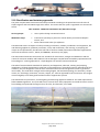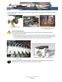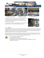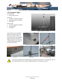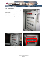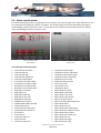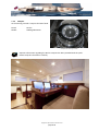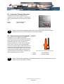
1
SY ANNAGINE DYKSTRA 110’ VERSION: 17-08-2011 OPERATION MANUAL Contents 1 Introduction ............................................................................................................................. 5 2 2.1 2.2 2.3 2.4 2.5 2.6 2.7 2.8 General information and craft data .......................................................................................... 6 General data ..................................................................................................................................... 6 Manufacturer and architect ............................................................................................................. 6 Main dimensions .............................................................................................................................. 6 Class & Loadline dimensions ............................................................................................................ 6 Masses .............................................................................................................................................. 6 Tank capacities ................................................................................................................................. 7 Engine data ....................................................................................................................................... 7 Electrical data ................................................................................................................................... 7 2.8.1 2.8.2 Direct current ...........................................................................................................................................................................................7 Alternating current...................................................................................................................................................................................7 2.9 2.10 Steering data .................................................................................................................................... 7 Classification and statutory approvals ............................................................................................. 8 3 3.1 3.2 Hull construction...................................................................................................................... 9 General ............................................................................................................................................. 9 Typical plate thickness and frames .................................................................................................. 9 4 4.1 4.2 4.3 General arrangements ........................................................................................................... 10 Profile & interior plan ..................................................................................................................... 10 Profile & deck plan ......................................................................................................................... 11 Sail and rigging plan ....................................................................................................................... 12 5 5.1 5.2 5.3 Installations ........................................................................................................................... 13 Engine room ................................................................................................................................... 13 Engine room ventilation ................................................................................................................. 14 Main engine.................................................................................................................................... 15 5.3.1 5.3.2 5.3.3 5.3.4 Main engine type ................................................................................................................................................................................... 15 Engine alarm .......................................................................................................................................................................................... 15 Engine control ........................................................................................................................................................................................ 16 Bleeding the engine ............................................................................................................................................................................... 16 5.4 Propulsion system .......................................................................................................................... 17 5.4.1 5.4.2 5.4.3 5.4.4 General................................................................................................................................................................................................... 17 Gearbox .................................................................................................................................................................................................. 17 Controllable pitch propeller ................................................................................................................................................................... 17 Stand-by seal .......................................................................................................................................................................................... 19 5.5 Generators...................................................................................................................................... 20 5.5.1 5.5.2 5.5.3 5.5.4 Generators type ..................................................................................................................................................................................... 20 Generator alarm ..................................................................................................................................................................................... 20 Generator control .................................................................................................................................................................................. 21 Bleeding the generators ......................................................................................................................................................................... 22 5.6 Fuel system ..................................................................................................................................... 23 5.6.1 5.6.2 5.6.3 5.6.4 5.6.5 General................................................................................................................................................................................................... 23 Fuel distribution and transfer system .................................................................................................................................................... 23 Refuelling ............................................................................................................................................................................................... 24 Fuel filters .............................................................................................................................................................................................. 25 Emergency fuel shut offs ........................................................................................................................................................................ 25 5.7 Sea water system ........................................................................................................................... 26 5.7.1 5.7.2 5.7.3 Electrical actuators of seacocks .............................................................................................................................................................. 26 Central seawater inlet manifold ............................................................................................................................................................. 26 Central seawater overboard stack ......................................................................................................................................................... 27 5.8 Exhaust system ............................................................................................................................... 28 Copyright © Wijma Marine Consultants 2011 page 2-96 OPERATION MANUAL 5.8.1 5.8.2 Engine .................................................................................................................................................................................................... 28 Generators ............................................................................................................................................................................................. 28 5.9 Fresh water system ........................................................................................................................ 29 5.9.1 5.9.2 5.9.3 General................................................................................................................................................................................................... 29 Hot water circulating system.................................................................................................................................................................. 29 Water maker .......................................................................................................................................................................................... 30 5.10 Grey water system ......................................................................................................................... 32 5.10.1 5.10.2 General................................................................................................................................................................................................... 32 Grey water collection boxes ................................................................................................................................................................... 32 5.11 Toilet system (black water) ............................................................................................................ 34 5.11.1 5.11.2 Using the toilets ..................................................................................................................................................................................... 34 Black water system ................................................................................................................................................................................ 34 5.12 Bilge pumping system .................................................................................................................... 36 5.12.1 5.12.2 5.12.3 Main system ........................................................................................................................................................................................... 36 Backup system ....................................................................................................................................................................................... 37 Bilge alarm ............................................................................................................................................................................................. 38 5.13 Deck wash system .......................................................................................................................... 39 5.13.1 5.13.2 Sea water deck wash .............................................................................................................................................................................. 39 Fresh water deck wash ........................................................................................................................................................................... 39 5.14 5.15 Deck shower ................................................................................................................................... 39 Interior ventilation system ............................................................................................................. 40 5.15.1 5.15.2 Interior ventilation ................................................................................................................................................................................. 40 Galley ventilation ................................................................................................................................................................................... 40 5.16 5.17 Galley equipment ........................................................................................................................... 40 Air conditioning – cooling & heating .............................................................................................. 41 5.17.1 5.17.2 Cooling the yacht ................................................................................................................................................................................... 41 Heating the yacht ................................................................................................................................................................................... 43 5.18 5.19 Refrigerators and freezers.............................................................................................................. 44 Steering system .............................................................................................................................. 45 5.19.1 5.19.2 5.19.3 General................................................................................................................................................................................................... 45 Emergency steering arrangement .......................................................................................................................................................... 45 Autopilot steering arrangement ............................................................................................................................................................. 46 5.20 Hydraulic system ............................................................................................................................ 47 5.20.1 5.20.2 5.20.3 Hydraulic power supply .......................................................................................................................................................................... 47 Hydraulic consumers .............................................................................................................................................................................. 48 Manual override of hydraulic system ..................................................................................................................................................... 50 5.21 5.22 5.23 5.24 5.25 5.26 Bow thruster................................................................................................................................... 51 Anchoring arrangement ................................................................................................................. 52 Deck winches and furler operation ................................................................................................ 53 Boarding platform .......................................................................................................................... 54 Navigation lights ............................................................................................................................. 55 Air horn and compressor ................................................................................................................ 56 6 6.1 Electrical installation .............................................................................................................. 57 Alternating current system ............................................................................................................ 57 6.1.1 6.1.2 6.1.3 6.1.4 Shore power supply ............................................................................................................................................................................... 57 Generator power supply ........................................................................................................................................................................ 57 Power supply by battery bank via inverters ........................................................................................................................................... 58 AC Switch boards ................................................................................................................................................................................... 59 6.2 Direct current system ..................................................................................................................... 60 6.2.1 6.2.2 6.2.3 6.2.4 6.2.5 6.2.6 DC battery banks .................................................................................................................................................................................... 60 DC main switches ................................................................................................................................................................................... 60 DC switch boards .................................................................................................................................................................................... 61 Battery chargers ..................................................................................................................................................................................... 62 Emergency battery set ........................................................................................................................................................................... 62 Safety warnings ...................................................................................................................................................................................... 63 6.3 PLC system...................................................................................................................................... 64 6.3.1 6.3.2 General................................................................................................................................................................................................... 64 Manual override ..................................................................................................................................................................................... 64 Copyright © Wijma Marine Consultants 2011 page 3-96 OPERATION MANUAL 6.4 Alarm control system ..................................................................................................................... 65 7 7.1 Navigation & communication ................................................................................................. 67 Navigation equipment .................................................................................................................... 67 7.1.1 7.1.2 7.1.3 7.1.4 7.1.5 Chart plotter and radar .......................................................................................................................................................................... 67 Global positioning system - GPS ............................................................................................................................................................. 67 Automatic identification system - A.I.S. ................................................................................................................................................. 68 Gyro compass ......................................................................................................................................................................................... 68 Compass ................................................................................................................................................................................................. 69 7.2 7.3 Sailing instruments ......................................................................................................................... 70 Communication equipment ........................................................................................................... 71 7.3.1 7.3.2 7.3.3 7.3.4 7.3.5 Emergency radio procedures ................................................................................................................................................................. 71 VHF radio – crew cabin........................................................................................................................................................................... 72 VHF radio – navigation desk and cockpit ................................................................................................................................................ 72 Sailor FleetBroadband ............................................................................................................................................................................ 73 Navtex .................................................................................................................................................................................................... 73 8 8.1 Safety equipment and recommendations ............................................................................... 74 Fire fighting system ........................................................................................................................ 74 8.1.1 8.1.2 8.1.3 8.1.4 8.1.5 8.1.6 8.1.7 8.1.8 Fire and smoke detection ....................................................................................................................................................................... 74 Main system ........................................................................................................................................................................................... 75 Backup system ....................................................................................................................................................................................... 76 Engine room fire fighting system ........................................................................................................................................................... 76 Portable fire extinguishers ..................................................................................................................................................................... 77 Fire suit .................................................................................................................................................................................................. 78 Escape way’s in the event of a fire ......................................................................................................................................................... 78 Fire fighting safety warnings .................................................................................................................................................................. 79 8.2 8.3 8.4 8.5 8.6 8.7 8.8 8.9 8.10 8.11 8.12 8.13 Inmarsat-C Distress Alarm Box ....................................................................................................... 80 Search and rescue transponder – S.A.R.T. ..................................................................................... 80 Epirb ............................................................................................................................................... 81 Liferafts........................................................................................................................................... 81 Inflatable dinghy storage................................................................................................................ 82 Risk of flooding and stability .......................................................................................................... 82 Cockpit drainage ............................................................................................................................. 82 Mooring and Towing ...................................................................................................................... 83 Man overboard prevention ............................................................................................................ 83 Jon buoys ........................................................................................................................................ 83 Field of vision from the helm position ........................................................................................... 84 First aid kit ...................................................................................................................................... 84 9 9.1 9.2 9.3 9.4 9.5 Environmental considerations ................................................................................................ 85 Fuel and oil spillage ........................................................................................................................ 85 Discharge and disposal of waste .................................................................................................... 85 Excessive noise and exhaust emissions .......................................................................................... 85 Wake and wash .............................................................................................................................. 85 Paint, cleaning agents and other substances ................................................................................. 85 10 10.1 10.2 10.3 10.4 10.5 10.6 Maintenance .......................................................................................................................... 86 General care ................................................................................................................................... 86 Cleaning .......................................................................................................................................... 86 Lifting of the yacht ......................................................................................................................... 86 Winter storage ............................................................................................................................... 87 Painting........................................................................................................................................... 87 Anodic protection ........................................................................................................................... 88 Copyright © Wijma Marine Consultants 2011 page 4-96 OPERATION MANUAL 11 Disclaimer .............................................................................................................................. 88 12 Annex A: Joining manuals ...................................................................................................... 89 13 13.1 13.2 Annex B: Drawing list ............................................................................................................. 94 Design drawings ............................................................................................................................. 94 System drawings ............................................................................................................................ 94 1 Introduction This manual has been compiled to help the crew to operate the yacht with safety and pleasure. It contains details of the yacht; the equipment supplied or fitted, its systems and information on their operation. Please read it carefully, and familiarize yourself with the installation before using it. This operation manual is not a detailed maintenance or trouble-shooting guide. In the case of difficulty, refer to the supplier or his representative. If a maintenance manual of an installed component is provided, use it for the yacht's maintenance. Always use trained and competent people for maintenance, repairs or modifications. Modifications that may affect the safety characteristics of the yacht should be assessed, executed and documented by competent contractors. The crew should be familiar with the use of all safety equipment and emergency manoeuvring (man overboard recovery, towing, etc.). Regularly organize drill sessions for the crew. All persons should wear a suitable buoyancy aid (life jacket/personal floatation device) when on deck. Note that, in some countries, it is a legal requirement to wear a buoyancy aid that complies with their national regulations at all times. Please keep this manual in a secure place, and hand it over to the new owner when you sell the yacht. Copyright © Wijma Marine Consultants 2011 page 5-96 OPERATION MANUAL 2 General information and craft data 2.1 General data Type: Name: Flag state: Homeport: IMO Number: MMSI: Call sign: Keel laying date: Class notation: Dykstra 110’ Classic Sloop Annagine Malta Valletta 1010234 248707000 9HB2038 May 2007 +100A1 SSC Yacht Mono G6 / MCA Short-range 2.2 Manufacturer and architect Builder: Jacht Ontwikkelings Maatschappij Holland BV Leidsegracht 13-15 1017 NA Amsterdam The Netherlands Architect: Gerard Dykstra & Partners Kruithuisstraat 21 1018 WJ Amsterdam The Netherlands 2.3 Main dimensions Length over all (LOA): Length over deck (LDECK): Waterline length (LWL): 33.90 m 33.25 m 26.05 m Beam over all (BOA): Beam moulded (BH): Beam waterline (BWL): 7.10 m 7.05 m 6.72 m Draft canoe body: Draft keel: Depth at midship: 1.26 m 4.30 m 2.75 m (including guard rails) Design condition Design condition 2.4 Class & Loadline dimensions LR rule length (LRULES): Loadline length (LLL): Freeboard: 25.85 m 29.42 m 1.40 m 2.5 Masses Displacement floatation FWL: Displacement scantling WL (FWL +100): Total ballast weight: 99.0 Tons 114.0 Tons 47.0 Tons Copyright © Wijma Marine Consultants 2011 page 6-96 OPERATION MANUAL 2.6 Tank capacities Diesel tank – port side: Diesel tank – starboard: Diesel day tank – in engine room: 1700 ltr 1700 ltr 240 ltr Water tank – port side: Water tank – starboard: 1700 ltr 1700 ltr Grey water tank – port side: Black water tank – starboard: 500 ltr 500 ltr 2.7 Engine data Engine type: Model: Maximum engine power: Rotations: Volvo Penta D7A-B TA 148 kW [199 HP] 2300 rpm Gearbox type: Model: Ratio: Twin Disc MG5050V 2.50:1 Propeller: Shaft: 4 Blade Ø 750 mm Steel Ø 60 mm Fuel consumption (according to specifications Volvo) 2.8 Electrical data 2.8.1 Direct current Capacity engine & generator Std battery bank: Capacity generator Pt battery bank: Capacity service battery bank: Emergency battery: Alternator start battery: 2.8.2 Alternating current Voltage: Frequency: Phases: 24V DC / 225 Ah 24V DC / 225 Ah 24V DC / 1650 Ah 24V DC / 200 Ah 55 A (Standard alternator will probably be replaced by …. A alternator) 400 V 50 Hz Three Isolation transformer: Exendis MarPower PSC II / 25 kW 31 kVA / 170V-520V 40Hz-70Hz Generator type: Model: Capacity: Amps: Rotations: 2 x Northern Lights M944W 26 kW; 400 VAC; 3 phase; 50 Hz 3 x 40A 1500 min-1 2.9 Steering data Type: Reduction Edson Chain & Wire Rope 3 ¼ turns of wheel from portside to starboard Copyright © Wijma Marine Consultants 2011 page 7-96 OPERATION MANUAL 2.10 Classification and statutory approvals The yacht complies with construction and safety standards according to the Special Service Craft rules of Lloyd’s Register and to the MCA Large Yacht code 2. This means that the yacht is registered as a Commercial Vessel. Class notation: +100A1 SSC Yacht Mono G6 / MCA Short-range Service group 6: • covers yachts having unrestricted service. MCA Short-range: • restricted to operating in forecast or actual wind of a maximum Beaufort Force 4, and within 120 nautical miles of a safehaven. The MCA Code covers all aspects of safety including construction, stability, installations and equipment, fire and lifesaving appliances, pollution prevention, survey and certification, and manning. In preparing this unique set of requirements, the MCA has still had to conform to IMO (International Maritime Organisation) rules and conventions such as , SOLAS, and MARPOL, where they may apply. The International Load Line Convention sets standards of construction, strength and subdivision and the criteria for minimum stability and freeboard. The SY Annagine complies with the stability requirements and has undergo an "inclining experiment". Lloyds Register has issued a Load Line Certificate. The Code of Practice details standards of machinery and equipment, electrical, steering and pumping installations. All these requirements come from a long experience in ship safety practice and analysis of past accidents, they are designed to save the lives of those on board and at least give them time to get off the vessel safely. The Code deals at length with coaming heights, hull and deck openings, fire insulation, escape routes, etc. furnishings, mattresses, curtains, carpets, etc. must be approved to be fire and toxic safe. Engine rooms and galleys must have good insulation and fire suppression systems. The Code details fire protection, and fire fighting and lifesaving appliance standards. The radio requirements follow GMDSS regulations. The yacht will have to increase their safety equipment to include at least a second fire and bilge pump outside the engine room, life rafts, fire detection, and a SART. Copyright © Wijma Marine Consultants 2011 page 8-96 OPERATION MANUAL 3 Hull construction 3.1 General The hull of the Dykstra 110’ Classic Sloop is built of aluminium. The yacht is divided in forepeak, fore ship, midship, engine room and lazarette watertight compartments. The compartments are sealed by watertight bulkheads and watertight lead through of Roxtec. The tanks are integrated in the bottom structure of the yacht. The deck is reinforced with inserts for deck equipment and winches. Roxtec watertight bulkhead lead through The aluminium keel consists of a bulb shape. An aluminium balanced spade rudder is fitted. The aluminium rudder shaft has aluminium foundations for hull and top bearing. The carbon fibre mast is keel stepped. Separate information regarding the Roxtec watertight bulkhead lead through has been provided with the yacht. Please study this information carefully. 3.2 Typical plate thickness and frames Hull Frame spacing: Hull plating below cwl: Side plating: Transom plating: Frames: Tank top plating: Deck 500 mm 8 mm 6 mm 6 mm T130x8+80x8 mm 5 mm Superstructures Frame spacing: Deckhouse plating: Deckhouse beams: 500 mm 5 mm T70x50x6-7 mm Plating and built profiles: ALU 5083 H321 Deck plating: Deck inserts: Deck plating in way of mast: Deck beams: Deck girders: Intercostal: Watertight bulkheads Watertight bulkhead plating: Watertight bulkhead beams: Extrusions: The “Structural” drawings can be found in the annexes of this manual. Copyright © Wijma Marine Consultants 2011 page 9-96 5 mm 15 mm 20 mm T100x6+60x6 mm T120x8+100x12 mm HP 50x5x12 mm 5 mm Various ALU 6082 T6 OPERATION MANUAL 4 General arrangements 4.1 Profile & interior plan Copyright © Wijma Marine Consultants 2011 page 10-96 OPERATION MANUAL 4.2 Profile & deck plan Copyright © Wijma Marine Consultants 2011 page 11-96 OPERATION MANUAL 4.3 Sail and rigging plan Rig type: Masthead sloop with cutter rig, fully battened mainsail with furling genoa and staysail. Keel stepped mast with three sets of spreaders. Spars: Carbon fibre, with three sets of spreaders and rod rigging. Projected sail areas Main sail: Genoa: Furling genoa (yankee): Staysail: Gennaker: 294 m2 337 m2 270 m2 111 m2 718 m2 Rig dimensions E measurement: P measurement: I measurement: J measurement: BAS measurement: HBI measurement: 12.50 m 39.34 m 41.88 m 12.75 m 2.50 m 1.53 m Air draft @ scantling draft: 45.20 m Copyright © Wijma Marine Consultants 2011 page 12-96 OPERATION MANUAL 5 Installations 5.1 Engine room The engine room is located below the deckhouse and the forward part of the cockpit. The bulkheads and all piping penetrations are watertight. The engine room is heavily insulated for noise and fire protection. The insulation material consists of Rockwoll covered with white Bondal plating. There are two entrances to enter the engine room: Hinging watertight door from the saloon Hatch at starboard side deck All the engine room entrances are watertight. The watertight door and the deck hatch should always be closed while sailing. When the door or the hatch are opened a visual indication is shown at the PLC screen and at the steering position. Door or hatch open warning at PLC screen Watertight engine room door Engine room hatch at starboard side deck Warning: Keep all entrances to engine room closed when engine or generator is running. Make sure engine room ventilation is running before entering. Use protective hearing aids when entering the engine room. Notify other crewmembers when entering the engine room. Keep inflammable liquids away from engine compartment. Turn lights on before entering the engine room. Beware of moving parts and do not wear baggy clothing near the machine while in operation. The “General system GA” drawing can be found in the annexes of this manual. This drawing gives an overview of the installed components in the engine room. Copyright © Wijma Marine Consultants 2011 page 13-96 OPERATION MANUAL 5.2 Engine room ventilation The engine room ventilation is based on a maximum air consumption of the engine, generator and the amount of air changes per hour of the engine room. Behind the starboard side grills of the deckhouse a fan has been fitted. The engine room ventilation system is based on overpressure provided by the fan which blows fresh air in the engine room. The air leaves the engine compartment through the port side grills fitted in the deckhouse side. When starting the engine or generator the engine room ventilation will be switched on automatically. 10 minutes after shutting down the engine or generator the engine room ventilation will be automatically switched off. The engine room ventilation can be switched on and off manually at the PLC screen. In the engine room ventilation ducts A-60 fire dampers are installed that are automatically controlled by an electrical thermal release sensor mounted on the side of the ventilator. In case of a power failure the fire dampers can be manually opened by using a key. The fire fighting monitoring system is installed in the saloon at starboard and gives an alarm as soon as a fire is detected. Engine room blower: Brand: Witt & Sohn Model: A-MU5/V0.78/355/G/3 Capacity: 4000 m3/hr Serial nr.: 42922.1 Flame damper Pt: Brand: ActionAir Model: 350 dia Serial nr.: ……………… Flame damper Std: Brand: ActionAir Model: 350 dia Serial nr.: 00165134 Engine room ventilation blower control at PLC screen Engine room ventilation inlet fan with fire dampers Engine room ventilation outlet fire damper Electrical thermal release for automatic operation of fire damper Engine room ventilation grill at side of the deckhouse Fire fighting monitoring system panel installed in the saloon The “Engine room ventilation” drawing can be found in the annexes of this manual. This drawing gives an overview of the installed components in the engine room. Separate information regarding the engine room ventilation blowers and the ActionAir flame dampers has been provided with the yacht. Please study this information carefully. Copyright © Wijma Marine Consultants 2011 page 14-96 OPERATION MANUAL 5.3 Main engine 5.3.1 Main engine type The Dykstra 110’ Classic Sloop “Annagine” is equipped with a Volvo Penta D7A-B TA engine. Main engine: Brand: Model: Power: Serial nr.: Volvo Penta D7A-B TA 148 kW / 2300 RPM 5310805349 Engine data read out is available at the starboard panel in the cockpit. Main engine Main engine panel When working on the main engine it is advised to disconnect the engine from the starting batteries to prevent accidental starting. This can be done by turning the main engine power switch into the OFF position. The switch is located at the main DC panel box direct behind the engine room door. Separate information regarding the Volvo Penta D7A-B TA engine has been provided with the yacht. Please study this information carefully. 5.3.2 Engine alarm The engine alarm panel is fitted behind the engine in the engine room. In case of an engine alarm an acoustic signal will sound in the cockpit. If possible, stop the engine immediately if an alarm sounds to avoid further damage. The engine will automatically shut down when an over speed or an oil pressure alarm occurs. During operation of the alarm panel watch out for rotating components and hot surfaces. Main engine panel Copyright © Wijma Marine Consultants 2011 page 15-96 OPERATION MANUAL 5.3.3 Engine control To start the main engine: 1. Check if cooling water inlet valve (on the central sea water inlet) is open. 2. Check if cooling water outlet valve (on the central sea water outlet) is open. 3. Check if the exhaust gas valve (in the lazarette) is open. 4. Check if the fuel valve at the day tank is open. 5. Check the oil level in engine and transmission. 6. Check coolant level. 7. Switch the engine starting battery main switch ON. 8. Put gearbox control lever in NEUTRAL (lever in the cockpit). 9. Start the engine with the starting key at the engine panel (Std panel in cockpit). To stop the main engine: 1. Put gearbox control lever in NEUTRAL (lever in the cockpit). 2. Leave engine running for 5 to 10 minutes (cool down period). 3. Push the stop button on the engine panel at the panel (Std panel in cockpit). NOTE: Should the engine not start when the “starting key” is turned for 10 – 20 seconds, release switch and wait 30-60 seconds; repeat the previous procedure. Never run the starter motor for than 30 seconds at a time. Never: Close main circuit switch whilst engine is running (risk of ruining regulator). Change circuit charge whilst engine is running. Before starting the engine make sure there is nobody in the water around the vicinity of the propeller and that nobody is in the engine compartment. 5.3.4 Bleeding the engine The fuel system must be bled, e.g. after changing fuel filter, if the fuel tank has been run dry and after long stops. 1. Put a suitable vessel under the fuel return (1). 2. Loosen the bolt. 3. Turn the engine over with the starter (max. 20 sec.) until fuel free of bubbles comes out. 4. Tighten the bolt. 5. Start the engine and make sure there are no leaks. Do not loosen the injector delivery pipes. If the delivery pipes are loose they must be changed. Copyright © Wijma Marine Consultants 2011 page 16-96 OPERATION MANUAL 5.4 Propulsion system 5.4.1 General The propulsion line is of the type V-drive. The engine is located at the aft side of the engine room and drives the sliding shaft which is connected to the gearbox. The gearbox is located forward in the engine room and drives the water lubricated propeller shaft. The propeller loads are absorbed by the installed thrust bearing installed behind the gear box. For the highest propulsive efficiency a controllable pitch propeller has been installed. The “Stern gear installation” drawing can be found in the annexes of this manual. This drawing gives an overview of the installed components in the engine room. 5.4.2 Gearbox The Twin Disc gearbox is installed forward in the engine room and is connected by a sliding shaft with the engine (V-drive). Gearbox: Brand: Model: Power: Serial nr.: Twin Disc MG 5050V 2.50: 1 100204 Gearbox Separate information regarding the Twin Disc MG 5050V gearbox has been provided with the yacht. Please study this information carefully. The manual contains a maintenance record which has to be followed and completed after maintenance. 5.4.3 Controllable pitch propeller Controllable pitch propellers (CPP) for marine propulsion systems have been designed to give the highest propulsive efficiency over a broad range of speeds. By adjusting the blade pitch, the optimum efficiency can be obtained and fuel can be saved. Also, the controllable pitch propeller has a "vane"-position, which is useful with combined sailing / motor vessels as this position gives the least water resistance when under sail. The advantages of the controllable pitch propeller are: Improved manoeuvring, especially when going astern and at low speeds. The optimum loading for the engine can be obtained in all operational conditions. Maximum power at all speeds by reducing the pitch. It is possible to change the pitch at any speed/power condition. Reduced fuel consumption. Little water resistance in sailing position. When using both sail- and engine power at the same time it is possible to change the pitch to utilize the combination of both wind and engine to the max. The pitch of the propeller can be controlled with the joystick at the steering position. When under sail the “Sailing mode” indication light will tell when the blades of the propeller are in the vane-position. It is possible to motor astern by turning the blades, however it is recommended to use the engine morse control. Copyright © Wijma Marine Consultants 2011 page 17-96 OPERATION MANUAL The controllable pitch propeller unit is hydraulically controlled and powered by the main hydraulic system (see chapter 5.20). Controllable pitch propeller Controllable pitch propeller unit Controllable pitch propeller control at steering position and sailing mode indication light Manual Pitch adjustment: In case of failure of the hydraulic components or control system it is possible to do pitch adjustment by hand as follows: 1. Make sure there is a by-pass between pressure and return connection of the eaton motor. This can be done by putting the hydraulic valve of the pitch control in the middle position. 2. To adjust the pitch manually put a wrench on shaft (1) and turn the shaft by hand. Block valves platform and mast winches located in forward part engine room Controllable pitch propeller unit – manual adjustment Separate information regarding the Mekan controllable pitch propulsion system has been provided with the yacht. Please study this information carefully. Copyright © Wijma Marine Consultants 2011 page 18-96 OPERATION MANUAL 5.4.4 Stand-by seal On the propeller shaft a stand-by seal is installed. When problems arise with the main seal, the stand-by seal should be inflated to prevent water coming into the yacht. When the stand-by seal is inflated the shaft should not be rotated as this will damage the seal. The stand-by seal pump is stored with the bicycles in the lazarette. Warning! Do not rotate the shaft when the stand-by seal is inflated. Stand-by seal mounted at stern tube Stand-by seal principle Separate information regarding the stand-by seal has been provided with the yacht. Please study this information carefully. Copyright © Wijma Marine Consultants 2011 page 19-96 OPERATION MANUAL 5.5 Generators 5.5.1 Generators type Two Northern Lights M944W.5, 26kW at 1500 rpm, are installed in the engine room. The generators are equipped with local engine control panels and are installed in manufacturers supplied sound shields which are flexible mounted on the generators foundation. The installed generators supply power to the following systems: Alternating Current (AC) electrical system Hydraulic system by use of PTO’s (power take of) Generator During normal use of yacht one generator is for powering the electrical system and the other generator can be used for powering the hydraulic system. In case a greater demand of power is required for one of the systems the second generator can be switched on. For the electrical system each generator has his own bus bar which are separated from each other when the electrical installation is powered by both generators. In case the electrical system is powered by one generator the two bus bars are connected to each other. When using the bow thruster both generators are needed for powering the hydraulic system. In this case the generator for powering the electrical system will be automatically switched to the hydraulic mode for a period of 15 minutes. Pt generator: Brand: Model: Capacity: Serial nr.: Northern Lights M944W.5 26kW at 1500 rpm 9444-40577C Std generator: Brand: Model: Capacity: Serial nr.: Northern Lights M944W.5 26kW at 1500 rpm 9444-40575C Separate information regarding the Northern Lights M944W.5 generators has been provided with the yacht. Please study this information carefully. 5.5.2 Generator alarm Each generator is fitted with a system to protect it from high water temperature or low oil pressure. Generator sets have shutdown systems to stop the engine. The alarm will be monitored by the PLC system. The PLC system will also monitor overcurrent of one of the generators. In case an overcurrent occurs the alarm will be listed on the PLC screen. Copyright © Wijma Marine Consultants 2011 page 20-96 OPERATION MANUAL 5.5.3 Generator control The generators can be switched on/off at the PLC screen or with the local engine control panel. The PLC gives the option for starting the generator for the electrical system or for the hydraulic system. To start the generator: 1. Check if cooling water inlet valve (on the central sea water inlet) is open. 2. Check if cooling water outlet valve (on the central sea water outlet) is open. 3. Check if the exhaust gas valve (in the lazarette) is open. 4. Check if the fuel valve at the day tank is open. 5. Check the oil level in generator. 6. Check coolant level. 7. Switch the engine starting battery main switch ON. 8. Start the generator with local control panel in the engine room or the “generator on” button on the PLC screen. Generator cooling liquid tank To stop the main engine: 1. Shut down the generator with local control panel in the engine room or the “generator off” button on the PLC screen. Generator local engine control panel in the engine room Generator (hydraulic mode) control at PLC screen Generator (electrical mode) control at PLC screen Copyright © Wijma Marine Consultants 2011 page 21-96 OPERATION MANUAL 5.5.4 Bleeding the generators Fuel system air bleeding may be needed when: After fuel has been added to a newly installed engine. A new fuel filter is installed. The engine has run out of fuel. The fuel lines, injection pump, or any other fuel system component has been removed and installed. After changing the fuel filter, air only needs to be bled from the fuel filter. To do this: a) Loosen the air vent plug (1) on the fuel filter by about 1-1/2 turns. (Be sure to cover the vent with a cloth to prevent fuel from splashing.) b) Turn the priming pump cap on the fuel feed pump counterclockwise to unlatch it. Move the priming pump plunger (2) up and down. c) Close the air vent plug when no more air bubbles can be seen in the fuel flowing from the air vent plug hole. To bleed air at the fuel injection pump: a) Turn the air vent plug (3) about 1-1/2 turns to loosen it. (Cover the vent with a cloth to prevent fuel from splashing.) b) Pump the feed pump cap up and down. c) When there are no air bubbles to be seen in the fuel flowing from the air vent plug hole, push down the priming pump cap and turn it clockwise to lock it in place. Note: Do not close the air vent plug before locking the priming pump cap in place, because the internal pressure in the pump will prevent the priming pump cap from returning to the original position. If the engine does not start after this bleeding process, loosen a fuel line at the injector while cranking the engine with the starter motor until pure fuel escapes. Then tighten the connections. Do each line one-at-a-time. After the engine has started, use a piece of cardboard to look for fuel leaks. Copyright © Wijma Marine Consultants 2011 page 22-96 OPERATION MANUAL 5.6 Fuel system 5.6.1 General The two diesel tanks with a total capacity of 3400 litres are integrated in the bottom structure of the yacht. The fuel tanks are not connected to each other. In the engine room a day tank with a capacity of 240 litres has been installed at the starboard side. The ventilation lines of the diesel tanks are connected to each other and led to the mast of the yacht. All tanks are provided with electronic gauges for monitoring the tank levels. The tank contents can be read out from the PLC screen. The day tank is equipped with an additional magnetic level gauge at the side of the tank. Day tank with magnetic level gauge in the engine room at Std Tank monitoring at PLC screen Tank filling station with drain (aft) 5.6.2 Fuel distribution and transfer system To transfer fuel from the main tanks to the day tank an electrical and a manual transfer pump have been installed in the engine room. The electrical transfer pump can be set to pump automatically by the PLC system once reaches a set level. The fuel tank selection valve can be found behind the starboard sea strainer forward in the engine room. With this valve suction from the port side or starboard side fuel tanks can be selected. The returns of the main engine and both generators are routed back to the day tank. The day tank is provided with an overflow into the selected main tank. Fuel transfer pump: Brand: Sterling Sihi Model: AOHA1201AAAFJOAO Manual or electrical pump selection valve located under day tank Capacity: Serial nr. : approx. 2.5 m3/h @ 1450 rpm TR1351357-01 Electrical fuel transfer pump located below day tank Manual fuel transfer pump located at the day tank Separate information regarding the Sterling Sihi fuel transfer pump has been provided with the yacht. Please study this information carefully. Copyright © Wijma Marine Consultants 2011 page 23-96 OPERATION MANUAL Pt or Std fuel tank selection valve located behind the Std sea strainer Pt & Std generator and engine fuel distribution manifold Fuel overflow, returns & ventilation lines to day tank At the bottom of the day tank two drains are fitted. With the port valve the day tank can be drained two one of the main tanks. In case fuel must be transferred from one main tank to the other this valve must be opened. The other drain is meant for water drainage. It is recommended to plug of this drain to prevent accidentally spillage of diesel. Day tank drain to main tanks valve 5.6.3 Refuelling The filling points are located on the side decks to fill the portside and starboard fuel tanks respectively. When refuelling open the additional ventilation lines fitted to each box to allow the air to escape when filling. In the filling stations a drain connected to the central draining system has been installed. This drain has to been plugged off during bunkering to prevent spillage of fuel overboard. When refuelling never allow anyone to smoke in the vicinity of the yacht or the dockside where the fuel is being piped from. If fuel is spilt it should be cleaned up promptly and the waste disposed of ashore. If a little diesel fuel is spilt into the water then washing up liquid can disperse the fuel. Do not refuel while the engine is running. Do not smoke during refuelling. The filling stations are only suitable for gravity filling. During bunkering the drain of the filling station has to be plugged of to prevent spilling off fuel overboard. Copyright © Wijma Marine Consultants 2011 page 24-96 OPERATION MANUAL 5.6.4 Fuel filters In the fuel transfer line to the day tank a double fuel filter has been installed to ensure clean and filtered diesel in the day tank. The double fuel filter has been installed below the hydraulic buffer tank next to the day tank. The fuel filters of the engine and the generators are supplied by respectively Volvo Penta and Northern Lights and are mounted close to the machineries. Fuel main filter installed below the hydraulic buffer tank Fuel main filter: Brand: Separ Model: SWK 2000/10/um Capacity: 10 ltr/min Main engine fuel filter Fuel main engine filter: Brand: Volvo Penta Part nr: Volvo 864315 Generator fuel filter Fuel generator filters: Brand: Northern Lights Part nr: 944W24-51201 Separate information regarding the fuel filters has been provided with the yacht. Please study this information carefully. 5.6.5 Emergency fuel shut offs The fuel distribution manifolds at the day tank are fitted with emergency fuel shut offs. The fuel shut offs can be operated from the deck. In case of an emergency (e.g. fire in the engine room) these valves must be closed as soon as possible. Only operate the emergency fuel shut offs in case of an emergency as these valves will shut off the main engine. Emergency fuel shut off in engine room Emergency fuel shut off handle in lazarette The “Fuel diagram” and the “Vent and fill diagram” can be found in the annexes of this manual. Copyright © Wijma Marine Consultants 2011 page 25-96 OPERATION MANUAL 5.7 Sea water system 5.7.1 Electrical actuators of seacocks Electrical actuators are fitted on the central sea water inlet manifold and the central seawater overboard stack. The control box of the electrical actuators is fitted in the lazarette next to the engine room fire fighting control panel. In case of an electric failure the electrical actuators can be manually operated. Pull out and turn the yellow marked handle. Don’t operate the electrical actuators of the seacocks manually when the electricity is switched on. Electrical actuator of seawater outlet manifold Control box of the electrical actuators in the lazarette Electrical actuator of seawater outlet manifold 5.7.2 Central seawater inlet manifold The central sea water inlet manifold is located forward of the engine room. At each side of the manifold a seacock, electrical actuators and a sea water strainer has been installed. Close the manual seacocks before opening the sea water strainers for cleaning. Sea water strainer located at Pt en Std forward in the engine room Copyright © Wijma Marine Consultants 2011 page 26-96 OPERATION MANUAL The manifold provides seawater to the following systems (from port- to starboard side): 1. Bilge (or fire fighting) pump starboard 2. Fire fighting (or bilge) pump port side 3. Port side generator 4. Main engine 5. Starboard side generator 6. Chiller sea water pump 1 7. Chiller sea water pump 2 Watermaker has separate through-hull fitting located in bottom next to starboard generator. Central seawater inlet manifold located forward the engine room 5.7.3 Central seawater overboard stack The central sea water overboard stack is located at the aft side of the engine room. The following systems drain to the overboard stack: 1. Main engine 2. Port side generator 3. Starboard side generator 4. Sump tank located in engine room 5. Black water overboard 6. Grey water overboard 7. Bilge system 8. Chiller cooling water 9. Deckhouse, swallow nest and engine room hatch drains Spare (plug) 9 Central sea water overboard stack Copyright © Wijma Marine Consultants 2011 page 27-96 OPERATION MANUAL 5.8 Exhaust system 5.8.1 Engine The engine cooling water is taken from the central sea water inlet manifold located forward in the engine room. To cool down the exhaust temperature the cooling water is injected into the exhaust line. The engine has a wet/dry exhaust system which means that the cooling water is separated from the exhaust gasses in a water separator which is located in the engine room. The exhaust gasses run through the exhaust hose to the transom of the yacht at portside. The cooling water drains from the separator and flows overboard through the central sea water overboard stack. Main engine exhaust lift silencer located in the engine room Main engine exhaust separator located in the engine room Main engine exhaust overboard valve located in lazarette 5.8.2 Generators The generator cooling water is taken from the central sea water inlet manifold located forward in the engine room. To cool down the exhaust temperature the cooling water is injected into the exhaust line. The generators have a wet/dry exhaust system which means that the cooling water is separated from the exhaust gasses in a water separator which is located in the engine room. The exhaust gasses run through the exhaust hose to the transom of the yacht. The cooling water drains from the separator and flows overboard through the central sea water overboard stack. Pt Generators exhaust lift silencers located in the engine room Generator exhaust separators located in the engine room Generator exhaust overboard valves located in lazarette The raw water cooling system should be protected against freezing at sub- zero temperatures. The “Exhaust systems” and the “Seawater diagram” can be found in the annexes of this manual. Separate information regarding the Halyard exhaust system has been provided with the yacht. Please study this information carefully. Copyright © Wijma Marine Consultants 2011 page 28-96 OPERATION MANUAL 5.9 Fresh water system 5.9.1 General Two identical fresh water tanks of approximately 1700 litres each are fitted in the hull of the yacht under the floor in the saloon. The tank ventilation lines are led to the mast of the yacht. Each tank is provided with tank level indicators, which can be seen on the PLC screen. One can select which tank is used by opening or closing the corresponding tank with the selection valves located between the Std generator and the hydraulic reservoir tank. From the water tanks the water is pumped in the system and pressurized by the hydrophore pumps via a pressure tank to the consumers (toilets; taps; showers; dishwasher and washer/dryer). The filling points of the tanks are located on each side of the deck. Fresh water hydrophores located in aft side of engine room at Std Fresh water pressure tank located in aft side of engine room at Std Fresh water filling points located on each side of the deck (forward) Tank level indicators at the PLC screen The “Fresh water diagram” and the “Vent and fill diagram” can be found in the annexes of this manual. 5.9.2 Hot water circulating system Hot water to the consumers is provided by a hot water circulating system to ensure quick supply of hot water to all the consumers. The water is heated by the 150 litre boiler installed in the engine room. The hot water pump circulates the water in a loop of heavily insulated piping to all the consumers on board. Each consumer has his own dedicated valve to close or reduce the hot water capacity. Hot water circulating pump: Brand: Grundfos Model: UPS 32-80 B 180 Hot water boiler: Brand: Flamco Model: ESP 150 ltr Serial nr.: P 070138/01 Heat exchanger circulation pump: Brand: Grundfos Model: UPS 25-50 180 Serial nr.: 96281432 Separate information regarding the circulation pumps and the hot water boiler has been provided with the yacht. Please study this information carefully. Copyright © Wijma Marine Consultants 2011 page 29-96 OPERATION MANUAL The Flamco hot water boiler heats the water by the electric heating element. The hot water boiler and the hot water circulation pump have to be switched on/off at the PLC screen. In case of a failure of the electric heating element in the boiler, the water can be heated with warm water from the heat exchanger of one of the generators. A pump circulates the water in a closed system through the heat exchanger of generator to the heat exchanger in the boiler. It is recommended to use one generator (in electrical mode) to heat the boiler by opening the heat exchange valve in the generator box. Ensure that the heat exchange valve of the other generator is closed. Hot water circulation pump mounted on the side of the boiler Boiler hot water circulation pump of generator heat exchangers located under Pt floor in the engine room 150 ltr hot water boiler located forward in the engine room at Pt Heat exchanger valve of the generator 5.9.3 Water maker The water maker is installed in the engine room at the starboard side. It has his own sea water inlet with seacock located forward in the engine room almost midships left of the starboard generator. The seawater is pumped by two pumps (one for back-up) through a filter to the water maker. Water maker: Brand: Model: Capacity: Serial nr.: Schenker 210M220 210 litre/hr 28LTSCR9-15-05 Sea water pump 1: Brand: Cantoni C. Model: 8 LH 50 L-4 Serial nr.: ……………… Sea water pump 2: Brand: Cantoni C. Model: 8 LH 50 L-4 Serial nr.: 316660 The produced water from the water maker drains through a hardness filter to a Y-valve located in the engine room next to the watermaker. With this valve you can select which water tank has to be filled. Special attention should be taken to the maintenance of the water maker. Please follow the manufacturers recommended instructions. A special hose connection for flushing the water maker has been installed in way of the sink in the engine room at starboard. To prevent damage the Schenker water maker should be pickled if the system is not going to be used for an extended period. Copyright © Wijma Marine Consultants 2011 page 30-96 OPERATION MANUAL Schenker water maker located in the engine room at starboard Water maker sea water inlet located left of the starboard generator Sea water pump with filter located left of the starboard generator Second sea water pump located next to the starboard generator Water maker control box located above the water maker Water maker tank selection valves & hardness filter located in engine room With the tank selection valves it is possible to choose to which tank the desalinated water flows. During filling of the water tank by the water maker, always keep at least one of the water maker valves in the ‘open’ position. Make sure that the water maker seawater inlet and outlet seacocks are opened when the water maker is running. Separate information regarding the Schenker water maker has been provided with the yacht. Please study this information carefully. The “Fresh water diagram” and the “Seawater diagram” can be found in the annexes of this manual. Copyright © Wijma Marine Consultants 2011 page 31-96 OPERATION MANUAL 5.10 Grey water system 5.10.1 General A grey water tank of approximately 500 litres is fitted in the hull at port side of the yacht under the floor in the saloon. The tank ventilation line is led to the mast of the yacht. The grey water tank is equipped with a level sensor and alarm. The read-out is at the PLC screen at the navigation station. Grey water pump: Brand: BBA pompen & buizen Model: B40 BVBMC+m+Sc Capacity: 24 m3/hr Serial nr: 09-1915 All water from the washing basins, sinks, showers, dishwasher, washing machine and grey water collection boxes drain away through the central grey water line to the tank. The central grey water line is located under the corridor floor. There are two ways to empty the grey water tank: 1. By use of the grey water pump as installed in the engine room. Pumping the water overboard through the central sea water overboard stack located in the engine room. 2. By use of the deck pump out suction fitting. Grey water pump located in the aft side of the engine room at Pt Central sea water overboard stack located in the engine room Tank content read out at PLC screen Deck pump out suction fitting located at port side (middle) Prior to sailing grey water tank should be emptied. 5.10.2 Grey water collection boxes On board the yacht three grey water collection tanks have been installed to collect grey water. Grey water collection tank - in the engine room: Deck house fridge + fancoil drain Chiller drains Grey water collection tank - under floor owners cabin: Pt saloon fancoil drain Std saloon fancoil drain Owners cabin fancoil drain Guest cabin fancoil drain Copyright © Wijma Marine Consultants 2011 page 32-96 Grey water collection tank - under floor Pt guest cabin: Pt guest cabin fancoil drain Captain’s cabin fancoil drain Crew cabin fancoil drain Crew mess fancoil drain Galley fancoil drain Freezer + fridge drain Ice maker drain OPERATION MANUAL Grey water collection tank in the engine room Grey water collection tank under saloon floor Pt of stairs Grey water collection tank under floor Pt guest cabin Do not discharge the grey water tank close to shore or in any prohibited zone. Use harbour or marina pump-out facilities to empty the holding tank before leaving the harbour. Caution: The grey water tank will overflow into the owners and starboard guest showers if overfilled. The “Waste water diagram” can be found in the annexes of this manual. Copyright © Wijma Marine Consultants 2011 page 33-96 OPERATION MANUAL 5.11 Toilet system (black water) 5.11.1 Using the toilets The toilets are Tecma Sanitnautico Silence 24V electrical toilets which flush with fresh water. The toilets are operated by a small panel mounted adjacent to each toilet. The panel has two buttons marked ‘before use’ and ‘after use’. The ‘after use’ button adds a little water before the macerator pumps the bowl dry and the ‘before use’ button fills the bowl with a little water. The amount of water added to the bowl can be adjusted at the back of the control panel. The maximum use of water per flush is approximately 10 litres. Always use enough flushing water to avoid blockages. Toilet Toilet solenoid valve for flushing Toilet flush panel Use mild cleaning detergents as not to damage the rubber parts in toilets and pumps. Separate information regarding the Tecma toilets has been provided with the yacht. Please study this information carefully. 5.11.2 Black water system A black water tank of approximately 500 litres is fitted in the hull at starboard side of the yacht under the floor in the saloon. The tank ventilation line is led to the mast of the yacht. The black water tank is equipped with a level sensor and alarm. The read-out is at the PLC screen at the navigation station. All black water from the four toilets drain away through the central black water line to tank. The central black water line is located under the corridor floor. Copyright © Wijma Marine Consultants 2011 page 34-96 OPERATION MANUAL There are two ways to empty the black water tank: 1. By use of the black water pump as installed in the engine room. Pumping the water overboard through the central sea water overboard stack located in the engine room. 2. By use of the deck pump out suction fitting. Black water pump: Brand: BBA pompen & buizen Model: B40 BVBMC+m+Sc Capacity: 24 m3/hr Serial nr: 09-1393 The black water tanks should be cleaned on a regular basis by flushing water through the “waste” deck pump out suction fitting to prevent waste build up from blocking the lines. Tank content read out at PLC screen Black water pump located in the aft part of the engine room at Std Central sea water overboard stack located in the engine room Deck pump out suction fitting located at starboard Do not discharge the black water tank close to shore or in any prohibited zone. Use harbour or marina pump-out facilities to empty the holding tank before leaving the harbour. The “Waste water diagram” can be found in the annexes of this manual. Copyright © Wijma Marine Consultants 2011 page 35-96 OPERATION MANUAL 5.12 Bilge pumping system 5.12.1 Main system Installed on board are two pumps which can be used for the bilge pumping system or for the fire fighting system. The starboard pump is normally used for the bilge system. The port side pump for the fire fighting system. The bilge (or fire fighting) pumps can be switched on/off at the PLC screen The yacht is divided into the following bilge compartments: Fore peak Fore ship (crew compartment) Mid ship Engine room Lazarette Port side pump: Brand: Sterling Sihi Model: VW 20 53A”C” Capacity: 75 m3/h Serial nr.: NL 1352001-01 Bilge pump control at PLC panel Starboard pump: Brand: Sterling Sihi Model: VW 20 53A”C” Capacity: 75 m3/h Serial nr.: NL 1400560-01 The bilge manifold is located forward in the engine room at port side behind the boiler. The valves of the manifold are marked with their functions. The valves of the bilge compartment and the selected bilge pump have to be opened. It is recommended to select one bilge at the time in order to use the full capacity of the pump and to prevent air suction. In the suction line to the starboard pump an extra bilge suction line with valve (normally closed) has been installed. With the bilge pump overboard selection manifold located left of the main engine the running bilge pump has to be selected. As the starboard pump is used for the bilge system the aft valve of this manifold is normally opened. The bilge water is pumped overboard through the central sea water overboard stack. Bilge suction inlet and bilge water detector Bilge manifold located forward in the engine room at Pt Copyright © Wijma Marine Consultants 2011 page 36-96 Bilge (or FiFi) pump located in aft side of engine room at Pt OPERATION MANUAL Std (normally open) and Pt Bilge pump overboard selection manifold Bilge overboard at central sea water overboard stack Extra bilge suction point located in engine room fwd of Pt generator Ensure that the valve corresponding with the running pump at the bilge pump overboard manifold is opened before switching on the bilge pump. Warning: Do not let the bilge pump run dry longer than 5 minutes. Warning: Check function of all bilge pumps at regular intervals. Clear pump inlets from debris. Warning: When discharging bilge water always makes sure there is no oil or other matter in the bilges which will directly pollute the surface waters. Separate information regarding the Sterling Sihi bilge or fire fighting pumps has been provided with the yacht. Please study this information carefully. 5.12.2 Backup system A portable diesel powered pump is located in the lazarette. In case of an emergency where the main bilge pumping system fails this portable pump can be used as backup system. Diesel engine driven pump: Brand: Wavo pompen Engine: Hatz 1B20 Model: AP 220 1B20 Capacity: 30 m3/hr Weight: 46 kg Serial nr.: 17111001 100321 099 536 Portable diesel engine driven pump installed in the lazarette Warning: Do not let the portable pump run dry. Copyright © Wijma Marine Consultants 2011 page 37-96 OPERATION MANUAL 5.12.3 Bilge alarm In each compartment a bilge alarm sensor has been installed. In case bilge water is detected an audible alarm sounds throughout the yacht. The alarm can be seen on the PLC screen. Bilge alarm at PLC screen Bilge water detector The “Bilge-FiFi diagram” can be found in the annexes of this manual. Copyright © Wijma Marine Consultants 2011 page 38-96 OPERATION MANUAL 5.13 Deck wash system 5.13.1 Sea water deck wash For washing the deck with sea water the fire fighting system (see also chapter 8.1) can be used. The fire fighting pump is switched ON/OFF at the PLC screen. Hose connections can be found in the forepeak and lazarette of the yacht. Fire fighting (or bilge) Pumps Lazarette hose connection Forepeak hose connection Fresh water – deck wash valve Fresh water – deck wash hose connection 5.13.2 Fresh water deck wash A hose connection can be found at the anchor windlass for washing the deck with fresh water. The fresh water deck wash valve is located in the forepeak. The “Fresh water diagram” can be found in the annexes of this manual. 5.14 Deck shower At the swimming platform a fresh water deck shower has been installed. Deck shower at swimming platform Copyright © Wijma Marine Consultants 2011 page 39-96 OPERATION MANUAL 5.15 Interior ventilation system 5.15.1 Interior ventilation Interior ventilation is provided by means of natural ventilation with dorades, mushrooms and hatches on deck. Through the dorades fresh air is blown inside the yacht. The air can leave the yacht through the mushrooms provided in each cabin. Dorades and mushroom on deck providing natural ventilation Warning: All ventilation openings on deck are to be kept shut when under way. Separate information regarding the Solimar hatches and OceanAir Skyscreens has been provided with the yacht. Please study this information carefully. 5.15.2 Galley ventilation A fan is installed above the stove in the galley. The capacity is sufficient for evacuating smells and fumes originating from food preparation. The fan blows the air through the mushroom located above the galley on deck to the outside of the yacht. Galley ventilation Blower of the galley located above the stove 5.16 Galley equipment The galley worktop is made of stainless steel. The following equipment is installed in the galley: Cook plate Extractor hood Oven Microwave Dishwasher Gaggenau CI 49X Gaggenau AH900 Gaggenau EB 388 Gaggenau BM 241 Miele G7856 Separate information regarding the galley equipment has been provided with the yacht. Please study this information carefully. Copyright © Wijma Marine Consultants 2011 page 40-96 OPERATION MANUAL 5.17 Air conditioning – cooling & heating 5.17.1 Cooling the yacht The chilled water air conditioning system consists of two chillers installed in the aft part of the engine room at starboard and fan coils installed throughout the vessel. One chiller is needed for the system. The system is normally in the automatic mode, where there is an automatic switch in the selection of the chiller in use. Coolant piping connect the chillers to the fan coils and the chiller seawater system. The chiller consists of three major components: the compressor, the condenser, and the evaporator (or heat exchanger). The chiller is charged with a refrigerant that circulates throughout these components. The fan coils consist of two major components: the blower and coil. The coolant circulates through the piping from the chiller to each fan coil and back. In cooling mode, warm cabin air is drawn across the fan coil by the blower. Heat is removed from the air as it passes across the coil. The cooled air is then blown back into the cabin. The heat from the cabin air is transferred to the coolant circulating through the coil. The warmed coolant is pumped back to the chiller. The water is circulated through the chiller’s evaporator where the heat is transferred to the refrigerant in the evaporator coil, thus cooling the “chilled” coolant. The “warmed” refrigerant gas is returned to the compressor, compressed, and then circulated through the outer tube in the chiller’s condenser coil. Seawater is circulating through the condenser via the seawater system. The heat is transferred from the refrigerant to the seawater and pumped overboard taking the original cabin air heat with it. The circulating, “chilled” coolant is then pumped back through the piping to the fan coils in a continuous loop (as the cycle repeats). Chillers located in the engine room Fan coils installed throughout the vessel Fan coil control panel At each fan coil a frequency controller has been installed to prevent power peaks in the electrical system when a fan coil is switched on. The following fan coils are installed: Location: Deckhouse Saloon Owner’s cabin Guest cabin starboard Guest cabin port side Galley Captain’s cabin Crew mess Crew cabin Type: 1 x Marine Air AT 9HV 2 x Marine Air AT 18HV 1 x Marine Air AT 12HV 1 x Marine Air AT 9HV 1 x Marine Air AT 9HV 1 x Marine Air AT 12HV 1 x Marine Air AT 6HV 1 x Marine Air AT 9HV 1 x Marine Air AT 9HV Copyright © Wijma Marine Consultants 2011 page 41-96 Cooling capacity: 9000 BTU/hr 18000 BTU/hr 12000 BTU/hr 9000 BTU/hr 9000 BTU/hr 12000 BTU/hr 6000 BTU/hr 9000 BTU/hr 9000 BTU/hr OPERATION MANUAL Procedure to start up the chillers: 1. Open the sea cock valve of the seawater system (engine room). 2. Turn on the generator for power supply. 3. Set desired cabin temperatures at fan coil controls. 4. Turn all chillers on with the air-conditioning control box. 5. Verify that there is a good airflow from each fan coil. Air-conditioning control box located in engine room behind the chillers Chiller seawater inlets at manifold Chiller seawater outlet Chiller seawater pumps and Airconditioning circulation pumps in engine room below chillers Chiller control box located in engine room above chillers Frequency controller installed at each fan coil Warning: Never run one fan coil on cooling while running another one on heating. Caution: Check every six months the amount of anti-freeze and keep the value on 10%. While filling up the coolant make sure that anti-freeze percentage stays constant on 10%. Copyright © Wijma Marine Consultants 2011 page 42-96 OPERATION MANUAL 5.17.2 Heating the yacht Heating the yacht can be done by the reverse cycle method, where warm water is pumped from the module to the fan coils. For reverse cycle heating, the module’s refrigerant flows in the opposite direction through a reversing valve, thus adding heat to the coolant loop, instead of removing it as in the cooling mode. Reverse cycle heating electrical boiler in engine room next to the main engine Reverse cycle heating in combination with an electrical boiler is required depending on the outside water temperature: Outside water temperature < 10 oC: Reverse cycle heating in combination with an electrical boiler. Outside water temperature > 10 oC: Reverse cycle heating. NOTE: Never run one unit on cooling while running another one on heating. Separate information regarding the air conditioning system has been provided with the yacht. Please study this information carefully. The “Chilled water diagram” can be found in the annexes of this manual. Copyright © Wijma Marine Consultants 2011 page 43-96 OPERATION MANUAL 5.18 Refrigerators and freezers The following fridges and freezers are placed on board the yacht: 500 litre +4 OC Two doors fridge in the galley 500 litre -20 OC Two doors freezer in the galley +4 OC Singe door fridge in the deck house 170 litre The refrigerators and the freezers are cooled by a set of two compressors. Because only one compressor is needed for the system, the compressors are installed in a parallel configuration. To keep the hours of use equal you should switch over between the two compressors every month. The running hours of each compressor is given at the control panel. Gas (Freon R404A) is cooled down by the compressors and pumped through the piping and cooling systems of the fridges and freezers. Fridges and freezers in galley The compressors are placed beneath the floor in the galley and are cooled with cooling water from the hull tank. A Grundfoss pump circulates the cooling water through the compressors and the hull tank. In case there is a malfunction in the keel cooling system a back-up heat exchanger has been installed. By opening the back-up heat exchanger valves the compressor cooling water is cooled by the refrigerant of the air-conditioning system. Ensure that the chillers are switched on when the back-up heat exchanger needs to be used.The cool and freeze system and their components can be switched on/off at the control box located at starboard of the fridges and freezers in the galley. Cooling and freezing control box located in starboard locker next to fridges Compressors beneath galley floor Fridge in deckhouse Back-up heat exchanger valves Separate information regarding the refrigerators and freezers system has been provided with the yacht. Please study this information carefully. Copyright © Wijma Marine Consultants 2011 page 44-96 OPERATION MANUAL 5.19 Steering system 5.19.1 General The steering system is of the wire type manufactured by Edson. A wire runs from the quadrant on the rudder stock to block sheaves on port and starboard and then back to two block sheaves placed under the pedestal. At the pedestal the wire is connected to a chain that runs over a chain wheel. Reduction in steering is 3 ¼ turns of wheel from port to starboard. Quadrant and rudderstock bearings Steering wheel Make sure that no loose objects in the lazarette can obstruct the steering system. 5.19.2 Emergency steering arrangement Should any problem occur with the steering system, an emergency tiller can be placed on top of the rudder stock. The emergency tiller is kept in the lazarette at Std. Before the tiller can be placed on the rudderstock the circular metal plate in the cockpit floor should be removed. Alternatively the Autopilot can be used as an emergency steering system. Emergency steering arrangement Storage location of emergency steering tiller Copyright © Wijma Marine Consultants 2011 page 45-96 OPERATION MANUAL 5.19.3 Autopilot steering arrangement The autopilot steering machine consists of a hydraulic cylinder and an electrical controlled hydraulic pump. The steering course can be set and adjusted with the B&G pilot panel as installed at the navigation desk and at the steering position. Autopilot control at navigation desk and steering position Autopilot steering pump Autopilot ram Separate information regarding the B&G Auto pilot control has been provided with the yacht. Please study this information carefully. Copyright © Wijma Marine Consultants 2011 page 46-96 OPERATION MANUAL 5.20 Hydraulic system 5.20.1 Hydraulic power supply The hydraulic system consists of pumps installed on the power take offs (PTO) of both generators and an electrical “load sensing” pump of 2.2 kW located forward in the engine room at starboard. A buffer tank containing 120 litres of oil has been installed forward in the engine room at starboard (next to the diesel day tank). On the hydraulic page on the PLC screen you can switch one of the generators or the electrical pump on/off. Hydraulic page on PLC screen Pumps installed on the PTO’s of the generators in the engine room Electrical pump located in forward part of engine room at starboard Block valves of hydraulic pumps Hydraulic page on PLC screen Copyright © Wijma Marine Consultants 2011 page 47-96 OPERATION MANUAL 5.20.2 Hydraulic consumers Several block valves have been installed for the following installed hydraulic consumers on board. The following hydraulic components have been installed on board: A Block valves Pt cockpit winches located in engine room at Pt 1. Runner winch Pt Lewmar 88/3 SSHST SS SS 2. Primary winch Pt Lewmar 111/3 SSHST SS SS 3. Main sheet winch Pt Lewmar 88/3 SSHST SS SS 20 l/min 20 l/min 20 l/min 140 bar 140 bar 140 bar B Block valves Std cockpit winches located in engine room at Pt 4. Runner winch Std Lewmar 88/3 SSHST SS SS 5. Primary winch Std Lewmar 111/3 SSHST SS SS 6. Main sheet winch Std Lewmar 88/3 SSHST SS SS 20 l/min 20 l/min 20 l/min 140 bar 140 bar 140 bar Block valves Pt cockpit winches in Pt engine room Block valves Std cockpit winches in Std engine room C Block valves mast winches, boarding platform and prop pitch control located in engine room forward 7. Boarding platform Custom made 8. Mast winch forward Pt Lewmar 88/3 SSHST SS SS 20 l/min 140 bar 9. Mast winch aft Pt Lewmar 88/3 SSHST SS SS 20 l/min 140 bar 10. Mast winch forward Std Lewmar 88/3 SSHST SS SS 20 l/min 140 bar 11. Mast winch aft Std Lewmar 88/3 SSHST SS SS 20 l/min 140 bar 12. Locking pins platform Custom made 12 l/min 150 bar 13. Variable pitch control 12 l/min 150 bar Copyright © Wijma Marine Consultants 2011 page 48-96 OPERATION MANUAL Block valves mast winches, boarding platform and prop pitch in engine room forward Block valves mast winches, boarding platform and prop pitch in engine room forward D Block valves bow thruster and pressure intensifier located below crew cabin floor 14. Bow thruster Lewmar 400TAH 106 l/min 15. Pressure intensifier Lewmar 35 l/min 250 bar 140 bar E Block valves Navtec equipment located below crew cabin floor 16. Traveller cylinder Navtec A254-030-JOOX 17. Backstay cylinder Navtec A250-SE-090 18. Outhaul cylinder Navtec A250-030-SE 19. Boom vang cylinder Navtec -090 20. Furler cylinder Navtec Reckmann 15 l/min 7 l/min 7 l/min 7 l/min 7 l/min 350 bar 350 bar 350 bar 350 bar 350 bar F Block valves anchor windlass and genoa furler located in forepeak 21. Anchor windlass Lewmar 5000 22. Genoa furler Reckmann 50 l/min 40 l/min 140 bar 140 bar Block valve of bow thruster and Navtec equipment located below crew cabin floor Block valves of windlass and furler located in forepeak Copyright © Wijma Marine Consultants 2011 page 49-96 OPERATION MANUAL 5.20.3 Manual override of hydraulic system With the installed handles on the block valves the hydraulic functions can be manually operated. 1. Press the PLC designation button on the side of the generator running in the hydraulic mode. 2. Press and held in the button on the aft side of the load sensing valves installed in the forward part of the engine room (behind the starboard sea strainer). 3. Operate the hydraulic equipment manually with the installed handles on the block valves. The Navtec block valves are equipped with red buttons, which has to be pressed and turned for operation. PLC designation button on the side of generator local control boxes Load sensing valves of hydraulic pumps Separate information regarding the hydraulic system has been provided with the yacht. Please study this information carefully. Copyright © Wijma Marine Consultants 2011 page 50-96 OPERATION MANUAL 5.21 Bow thruster The bow thruster is installed underneath the floor in the crew cabin. The bow thruster is hydraulically driven. You can operate the bow thruster with the buttons on the cockpit floor at the steering position. Bow thruster: Brand: Lewmar 400TAH Stroke: 400 mm Bow thruster For operating the bow thruster both generators shall be running. In case one of the generator is in the electrical mode, it will be automatically switched over to the hydraulic mode for a period of 15 minutes. Hydraulic bow thruster located underneath floor in crew cabin Bow thruster operation buttons WARNING: The bow thruster should not be operated close to swimmers as powerful suction of water is generated when in use. Separate information regarding the Lewmar 4000TAH bow thruster has been provided with the yacht. Please study this information carefully. Copyright © Wijma Marine Consultants 2011 page 51-96 OPERATION MANUAL 5.22 Anchoring arrangement The chain locker is located in the forepeak. The length of the chain is 130 metres. The chain diameter is 13 mm galvanised steel with a breaking load of 142 tons. The weight of the stainless steel plow anchor is 137 kg. For lowering and weighing the anchor an hydraulic anchor windlass (Lewmar V8) has been installed on the foredeck. The remote control of this windlass can be found in the forepeak, next to the hatch opening. Anchor Anchor windlass: Brand: Lewmar Model: V8 Serial nr: ………… Main anchor: Brand: Manson plough Model: SSP 300 Weight: 137 kg Spare anchor: Brand: Lewmar CQR Model: 0056515 Weight: 110 kg Ketch anchor: Brand: Fortress Model: FX-55 Weight: 14.4 kg Anchor windlass The main anchor is operated by a hydraulic winch on the foredeck. Before dropping the anchor, the chain lock in front of the winch must be in the ‘remored’ position. Now slowly lower the anchor until the shaft is vertical by pressing the ‘down’ button next to the winch or on the remote control. You can now either drop the anchor by releasing the brake on the winch (after disengaging the drum) or slowly lower the anchor by keep pressing the ‘down’ button. The bitter end is connected to the yacht (eye in chain locker) with a piece of rope which can be cut in case of an emergency and failure with the anchoring arrangement. When anchoring in strong currents or winds it is recommended to attach a snuffer line on the chain to take the load off the winch. Anchor windlass control box Chain locker Bitter end To avoid personal injuries ensure that limbs, fingers and clothing are kept clear of the anchor rode and windlass during operation. Always ensure that there are no swimmers or divers nearby when dropping your anchor. Separate information regarding the Lewmar 5000 windlass has been provided with the yacht. Please study this information carefully. Copyright © Wijma Marine Consultants 2011 page 52-96 OPERATION MANUAL 5.23 Deck winches and furler operation The deck winches and the furler of the foresail can be operated by pressing the deck switches in the cockpit. Facing toward the deck switches: Slow Winch buttons: Left Winch buttons: Right Fast Furler buttons: Furler buttons: Left Right Clockwise Counter clockwise Cockpit winches and furler operation buttons Functions of the winches: Aft cockpit winch: Mid cockpit winch: Forward cockpit winch: Mast winches For running backstay’s / Staysail sheet For yankee sheet For main sheet For halyards, reefing lines, etc. Winches at cockpit Winches at mast To avoid personal injuries ensure that limbs, fingers and clothing are kept clear of the deck winches during operation. Separate information regarding the Lewmar winches has been provided with the yacht. Please study this information carefully. Copyright © Wijma Marine Consultants 2011 page 53-96 OPERATION MANUAL 5.24 Boarding platform A hydraulic controlled boarding platform is installed in the port side shell of the yacht. The boarding platform can be opened and closed by use of the PLC control or the remote control. Warning: During closing the boarding platform ensure nobody is standing on the platform. Boarding platform Boarding platform control at PLC Boarding platform remote control Copyright © Wijma Marine Consultants 2011 page 54-96 OPERATION MANUAL 5.25 Navigation lights Anchor mode: Anchor light at bow Sail mode: Port and starboard side lights Red above green mast lights Stern light Motor mode: Port and starboard side lights Steaming light Stern light Navigation lights at control panel The switches of the navigation lights are located on the main PLC panel. By pressing one of the mode buttons the applicable lights are directly switched on. Individual lights can be switched on/off by pressing the light at the PLC touch screen. Stern light Port and starboard side lights Red above green mast lights Steaming light Anchor light fitting The proper working of the navigation lights should be checked prior to each night sail. On the PLC control panel you can see if the navigation lights are functioning correctly. Copyright © Wijma Marine Consultants 2011 page 55-96 OPERATION MANUAL 5.26 Air horn and compressor In the lazarette an air compressor has been installed for the air horn which is mounted in the mast. The air compressor can be switched on/off at the PLC screen. The air horn control button is at the steering position. Air compressor: Brand: Kahlenberg Model: KA500 Serial nr.: 41641 Double air horn Air compressor with buffer tank located in the lazarette Air horn control at steering position Air compressor control at PLC It takes several minutes to build pressure to use the horn. Ensure that there is pressure on the system before leaving the harbour. Copyright © Wijma Marine Consultants 2011 page 56-96 OPERATION MANUAL 6 Electrical installation 6.1 Alternating current system The 3 phase 400V alternating current system can be powered by the shore power, the generator or by the service batteries via the installed inverters. 6.1.1 Shore power supply The 32A shore power inlet is fitted in the lazarette at the starboard aft side of the yacht. Three light indications show if there is power on each phase. A 32A isolation transformer has been installed to separate the ships ground and the shore ground. The isolation transformer is located in the forward part of the lazarette. Shore power inlet located in the lazarette at Pt Isolation transformer located in the lazarette forward at Pt Separate information regarding the Exendis isolation transformer has been provided with the yacht. Please study this information carefully. 6.1.2 Generator power supply At the PLC each generators can be switched on in the electrical mode. For more information regarding the generators see chapter 5.5. Generators installed in the engine room AC control at PLC Copyright © Wijma Marine Consultants 2011 page 57-96 OPERATION MANUAL The AC main switch board is designed in a manner that allows one generator to supply all vessels loads, either the port or starboard generator. The AC main switch boards also supports a split-bus configuration that allows both generators to be online simultaneously with the bus-tie opened and the consumers equally supported from either side of the bus-tie. AC main switch board 6.1.3 Power supply by battery bank via inverters When the yacht is not connected to shore power and none of the generators are running the power to the AC system is supplied by the service battery banks via the inverters installed in the engine room. All the power supply of the AC system are going through the Mastervolt Combi inverters. Next to the inverters in the engine room a “manual override panel” has been installed. In case of failure of the Combi inverters, power supply can be ensured by selecting the override function. Inverters located in the engine room at Pt Inverters manual override located in the engine room at Pt Separate information regarding the Mastervolt inverters has been provided with the yacht. Please study this information carefully. Never work on the electrical installation while the system is energized. Make sure that the shore power, generator and inverter have been switched off. Copyright © Wijma Marine Consultants 2011 page 58-96 OPERATION MANUAL 6.1.4 AC Switch boards The AC main switch board is located in the engine room. This switch board contains the circuit breakers of the main sources and some consumers in the engine room. Two distribution switch boards are installed in the fore ship (corridor aft of the mast) and in the aft ship (deck house at navigation desk). From the fore ship distribution switch board each cabin is provided with their own cabin panel. AC main switch board located in the engine room AC distribution board fore ship located in corridor aft of the mast AC distribution board aft ship located in deck house at navigation desk The “AC system” drawings are provided with the yacht. These drawings explain the installation. Copyright © Wijma Marine Consultants 2011 page 59-96 OPERATION MANUAL 6.2 Direct current system 6.2.1 DC battery banks The following battery banks have been installed on board for powering the DC system. Battery bank Engine and generator Std starting system: Generator Pt starting system: Service system Emergency system Power battery bank Capacity 24V / 225 Ah 24V / 225 Ah 24V / 1650 Ah 24V / 200 Ah Location of batteries Under floor in engine room at port Under floor in engine room at port Under floor guest cabins Pt and Std Under seat at navigation desk Starting battery banks Emergency battery bank under seat at navigation desk Separate information regarding the batteries has been provided with the yacht. Please study this information carefully. 6.2.2 DC main switches The battery main switches of the service and starting batteries are mounted on the side of the DC main switch board in the engine room. Battery banks can be coupled with the installed couple switches. In case of a power failure of a battery bank the system can be coupled to one of the other battery banks. PLC DC page Battery main switches and coupling switches Copyright © Wijma Marine Consultants 2011 page 60-96 OPERATION MANUAL 6.2.3 DC switch boards The DC main switch board is located in the engine room. This switch board contains the main switches and fuses of the battery banks and combi-chargers. The two distribution switch boards are installed in the fore ship (corridor aft of the mast) and in the aft ship (deck house at navigation desk). DC main switch board located in the engine room DC distribution board fore ship located in corridor aft of the mast DC distribution board aft ship located in deck house at navigation desk Copyright © Wijma Marine Consultants 2011 page 61-96 OPERATION MANUAL 6.2.4 Battery chargers Either shore power or the generators feed the 230 VAC battery chargers. The following battery chargers are installed on board for charging the starting and service battery banks: 2 x Mastervolt Combi 24/4000-120 1 x Mastervol Charger 24/100-C The engine and starboard generator can also be charged by the main engine alternator. Separate information regarding the Mastervolt Combi and Charger has been provided with the yacht. Please study this information carefully. Mastervolt Combi’s (Inverters and Chargers) installed in the engine room at Pt 6.2.5 Emergency battery set In case of an electric failure an emergency battery set has been installed below the seat at the navigation desk to power the following equipment: GPS (GP37) Seacock system engine room VHF (FM 2721) Satcom C Emergency lights NMEA Distribution To switch over from the service batteries to the emergency batteries a main switch has been installed on the DC switch board at the navigation desk. A Chargemaster 24/12-3 charger charges the emergency battery bank. DC emergency switch board with emergency main switch at navigation desk Emergency battery bank and charger below seat at navigation desk The “DC system” drawings are provided with the yacht. These drawings explain the installation and gives the installed materials. Copyright © Wijma Marine Consultants 2011 page 62-96 OPERATION MANUAL 6.2.6 Safety warnings Never: work on the electrical installation while the system is energized; do not modify the yacht’s electrical systems or relevant drawings. Installation, alterations and maintenance should be performed by a competent marine electrical technician. Inspect the system at least biennially. alter or modify the rated current amperage of overcurrent protective devices; install or replace electrical appliances or devices with components exceeding the rated current amperage of the circuit; leave the yacht unattended with the electrical system energized, except automatic bilge-pump, fire protection and alarm circuits. Connect metallic housings or enclosures of installed electrical appliances to the protective conductor system in the yacht (green or green with a yellow stripe conductor). Use double insulated or grounded (earthed) electrical appliances. Warning: Do not allow the shore-power cable end to hang in the water. An electrical field can be caused which can cause injury or death to nearby swimmers. Warning: To minimize shock and fire hazards. Turn off yacht’s shore-power connection switch before connecting or disconnecting shorepower cable. Connect shore-power cable to yacht’s inlet before connecting to shore-power source. Disconnect shore-power cable at shore-power source first. Close shore-power inlet cover tightly. Do not alter shore-power cable connectors, use only compatible connectors. Copyright © Wijma Marine Consultants 2011 page 63-96 OPERATION MANUAL 6.3 PLC system 6.3.1 General A PLC (Programmable Logic Controllers) is an industrial computer used to monitor inputs, and depending upon their state make decisions based on its program or logic, to control (turn on/off) its outputs. The PLC system as installed on board the yacht has the following functions: Switching main components on/off Monitoring of the installation Alarm control (see chapter 6.4) To enter the PLC menu a password (consisting of 5 numbers) to log in is required. Based on the user level you will have access to the all pages and functions or to a limited number of pages and functions. The following user levels are programmed in the system: User level: Super administrator (Floattech) Captain Crew Log in menu Access level Access to all pages & adjustment of all functions Access to all main pages & adjustments of all main functions Access to all main pages & adjustments of all main functions The PLC screen consist of a main page referring to the following pages: Motor mode Sail mode Harbour / Anchor mode Main – Status overview Pumps control Generator control DC Overview Status Overview Alarm Overview Tanks Lights PLC main page 6.3.2 Manual override Manual override of the PLC system is possible with the TL-switches installed in the main- and distribution switch boards. TL-switches in main- and distribution switch boards Copyright © Wijma Marine Consultants 2011 page 64-96 OPERATION MANUAL 6.4 Alarm control system The alarm monitoring system is integrated in the PLC system. An acoustic signal and a visual indication on the PLC screen will notify against a failure or problem. The acoustic signal can be switched off by pressing the “Acknowledge” button at the PLC screen. To reset the alarm for a period of 10 minutes press the “Silence alarm acknowledge” button at the PLC screen. Alarm overview screen of PLC system Alarm listing screen of PLC system Overview of the alarm functions: Fuel Daytank Low Alarm Fuel Daytank Low Fuel Daytank High Fuel Daytank High Alarm Fuel Filter Water Alarm Greywater Level Alarm 80% Greywater Level Alarm 100% Blackwater Level Alarm 80% Blackwater Level Alarm 100% Bilge Alarm Lazarette Bilge Alarm E.R. Bilge Alarm Mid ship Bilge Alarm Fore ship Bilge Alarm Saillocker FM200 Presure Alarm FM200 Cabinet Door Opened Watermaker Alarm Powerpack Oil Temp Alarm Powerpack Oil Level Alarm Airco Alarm Alarm Gen Pt Overcurrent Gen Pt Alarm Gen Std Overcurrent Gen Std Lamp Alarm Steam Light Lamp Alarm Anchor Light Mast Lamp Alarm Bow Anchor Light Lamp Alarm Stern Light Mast Watertank Pt Low Level Watertank Std Low Level Fuel Pt low Level Fuel Std low Level Low Battery Alarm Open Hatch Fore Peak Open Hatch Crew Cabin Open Hatch Crew Toilet Open Hatch Crew Shower Open Crew Mess Hatch Open Crew Mess Watertight Door Open Hatch Galley Open Hatch Guest Pt Open Hatch Owners Bathroom Open Hatch Guest Bathroom Std Open Hatch Owners Cabin Open Hatch Guest Cabin Std Open Hatch Salon Pt Open Hatch Salon Mid Open Hatch Salon Std Copyright © Wijma Marine Consultants 2011 page 65-96 OPERATION MANUAL Groundfault Testbutton Pushed Lamp Alarm Red Boardlight Lamp Alarm Green Boardlight Lamp Alarm Std NUC Red Light Mast Lamp Alarm Pt NUC Red Light Mast Lamp Alarm Std Green Light Mast Lamp Alarm Pt Green Light Mast Lamp Alarm Std Red Light Lamp Alarm Pt Red Light Open ER Watertight Door Open Hatch ER Deckhouse Burglar Alarm Open Hatch Aft Peak Std Open Hatch Aft Peak Aft Airvalve ER Pt Closed Airvalve ER Std Closed Vantilation Batteries Closed Warning: Do not acknowledge an alarm without visual inspection of the yacht. Copyright © Wijma Marine Consultants 2011 page 66-96 OPERATION MANUAL 7 Navigation & communication 7.1 Navigation equipment 7.1.1 Chart plotter and radar The yacht is equipped with a full time 3D chart rendering presentation. You can also choose a 2D top-down view of the navigation chart for traditional chart plotting. Radar image of spot-on accuracy can be overlaid with chart information. Not only is it done with the conventional 2D chart format, but also it can now be projected onto 3D chart presentation. Chart plotter Brand: Model: Radar Brand: Model: Furuno NavNet3D Furuno black box located under Std seat in saloon Furuno MFDBB NavNet3D chart plotter with radar function Separate information regarding the Furuno chart plotter and radar has been provided with the yacht. Please study this information carefully. 7.1.2 Global positioning system – GPS The Global positioning system (GPS) gives the position of the yacht and calculates its speed over ground. Brand: Model: Furuno GP-37 Global positioning system (GPS) Separate information regarding the Furuno GP-37 GPS has been provided with the yacht. Please study this information carefully. Copyright © Wijma Marine Consultants 2011 page 67-96 OPERATION MANUAL 7.1.3 Automatic identification system – A.I.S. The Automatic Identification System (AIS) is a system designed for identifying and locating vessels. AIS provides a means to electronically exchange ship data including: identification, position, course, and speed, with other nearby ships. The AIS-CTRX is an Automatic Identification System (AIS) Class B transponder with both receiving and transmitting capabilities. Data about your vessel is transmitted every 30 seconds or more, depending on configuration and speed. Brand: Model: True heading CTRX Automatic identification system (AIS) Separate information regarding the True heading AIS has been provided with the yacht. Please study this information carefully. 7.1.4 Gyro compass The gyrocompass provides the following data: Heading against the geographical meridian at the vessel speed up to 90 knots, latitude up to 80 degrees, roll and pitch angles up to 50 degrees; Rate of turn; Information about operation mode and failures. Brand: Model: Alphatron Minicourse Alpha minicourse gyro compass panel located under navigation desk Alpha minicourse gyro compass located under stairs to deckhouse Separate information regarding the Alphatron Minicourse gyro compass has been provided with the yacht. Please study this information carefully. Copyright © Wijma Marine Consultants 2011 page 68-96 OPERATION MANUAL 7.1.5 Compass At the steering console a compass has been fitted. Brand: Model: Ritchie FD600 globemaster Compass at steering console Separate information regarding the Ritchie compass has been provided with the yacht. Please study this information carefully. Copyright © Wijma Marine Consultants 2011 page 69-96 OPERATION MANUAL 7.2 Sailing instruments The B&G sailing instruments give data about the wind speed, wind direction, apparent boat speed and depth. All data can be seen on the B&G H3000 screens as fitted at the navigation desk, in the crew area and in the cockpit. Analogue displays with data about the Rudder angle; Magnified apparent wind angle; Apparent wind angle & Apparent wind speed are also fitted in the cockpit. Brand: Model: B&G Hydra 3000 B&G panels mounted on deckhouse B&G Black box B&G panel mounted at navigation desk Separate information regarding the B&G Sailing instruments has been provided with the yacht. Please study this information carefully. Copyright © Wijma Marine Consultants 2011 page 70-96 OPERATION MANUAL 7.3 Communication equipment 7.3.1 Emergency radio procedures Name of vessel: Call sign: MMSI number: SY Annagine 9HB2038 248707000 EMERGENCY RADIO PROCEDURES (only for GMDSS/DSC radios with DISTRESS button) • • • • • Check main battery switch is on, switch radio on, turn up volume Adjust “squelch” control so noise just disappears Press DISTRESS button once, select distress designation (if time) Press DISTRESS button again AND HOLD for 5 seconds until acoustic alarm stops Wait approximately 15 seconds – press transmit button on microphone and say slowly and clearly: MAYDAY, MAYDAY, MAYDAY THIS IS SY ANNAGINE, SY ANNAGINE, SY ANNAGINE MAYDAY SY ANNAGINE, MY POSITION IS ………………………………. (latitude and longitude, or true bearing FROM a known point) I AM ………. (sinking, on fire, etc.) I REQUIRE IMMEDIATE ASSISTANCE I HAVE ……. (number of persons on board and any other relevant information (e.g. availability of liferaft) OVER (this means “reply to me”) RELEASE THE TRANSMIT BUTTON KEEP LISTENING ON CHANNEL 16 FOR INSTRUCTIONS If you don’t know your position, don’t guess – give your last known position Copyright © Wijma Marine Consultants 2011 page 71-96 OPERATION MANUAL 7.3.2 VHF radio – crew cabin The SAILOR RT5022 can store and replay incoming calls. The display and menus have been separated into two with the main VHF functions shown in a 7-segment display and the DSC functions and settings shown in a graphic LCD display. The 7segment display is clearly readable at a distance and from even very wide angles. Both displays have text and indicators lit in red, which does not disturb the night vision. Brand: Model: Sailor RT5022 Sailor RT5022 VHF radio in crew cabin Separate information regarding the Sailor VHF Radio has been provided with the yacht. Please study this information carefully. 7.3.3 VHF radio – navigation desk and cockpit The Simrad RS87 is a modular VHF radio and Class D DSC (Digital Selective Calling) radiotelephone systems using a fully featured telephone-style handset (RS87). The unit supports the latest GMDSS requirements for non-SOLAS vessels from the International Maritime Organization (IMO) and will enable you to make digitally selected calls that are quicker and simpler to make than traditional voice calls using channel 16. Brand: Model: Simrad (FURUNO) RS87 SIMRAD RS87 VHF located at the navigation desk SIMRAD RS87 VHF located in the cockpit Separate information regarding the Simrad (Furuno) VHF Radio has been provided with the yacht. Please study this information carefully. Copyright © Wijma Marine Consultants 2011 page 72-96 OPERATION MANUAL 7.3.4 Sailor FleetBroadband The Sailor FleetBroadband satellite communication system provides the yacht with telephone, fax, e-mail and Internet access. Brand: Model: Thrane and Thrane Sailor FleetBroadband 500 Separate information regarding the Sailor FleetBroadband has been provided with the yacht. Please study this information carefully. Sailor FleetBroadband box Satellite phone located at the navigation desk Printer (fax) located in locker at starboard side of the saloon 7.3.5 Navtex The Furuno NX-700B NavTex (Navigational Telex) is an international automated medium frequency directprinting service for delivery of navigational and meteorological warnings and forecasts, as well as urgent marine safety information to ships. Brand: Model: Furuno NX-700B Furuno NX-700B Navtex box Furuno NX-700B Navtex Separate information regarding the Furuno Navtex has been provided with the yacht. Please study this information carefully. Copyright © Wijma Marine Consultants 2011 page 73-96 OPERATION MANUAL 8 Safety equipment and recommendations 8.1 Fire fighting system 8.1.1 Fire and smoke detection In each cabin and other spaces on board alarm switches and smoke detectors are mounted. The galley and engine room are provided with heat detectors. The fire fighting alarm panel can be found in the salon at starboard. At the panel two stop-buttons are mounted for the interior and for the engine room. When pressing the ‘Interior stop” all the ventilation on board (e.g. galley ventilation and fancoils) will be switched off and the emergency lightening will be switched on. Fire fighting detection control panel By pressing the “Engine room stop” the ventilation blowers and the fuel supply pumps will be switched off. The fire dampers will be closed and the emergency lights in the engine room will be switched on. Switch for general/fire alarm Smoke detector Separate information regarding the Fire fighting alarm panel has been provided with the yacht. Please study this information carefully. Copyright © Wijma Marine Consultants 2011 page 74-96 OPERATION MANUAL 8.1.2 Main system Installed on board are two pumps which can be used for the bilge pumping system or for the fire fighting system. The port side pump is normally used for the fire fighting system. The starboard pump is for the bilge system. The fire fighting (or bilge) pumps can be switched on/off at the PLC screen. The valve of the suction line of the applicable fire fighting (or bilge) pump has to be opened at the central sea water inlet manifold before the pump is switched on. Fire fighting pump control at PLC panel With the fire fighting pump selection manifold located behind the two pumps the used pump has to be selected. As the port pump is used for the fire fighting system the portside valve of this manifold is normally kept open. Std FiFi and Pt FiFi pump at central seawater inlet manifold FiFi (or bilge) pump located in aft side of engine room at Pt Std and Pt (normally open) FiFi pump selection manifold Fire fighting hose connections can be found at the following locations: In the lazarette (with 15 meter fire fighting hose) In the engine room (aft at Pt) In the forepeak (with 15 meter fire fighting hose) FiFi hose connection lazarette FiFi hose connection in engine room FiFi hose connection forepeak Warning: Do not let the bilge pump run dry longer than 5 minutes. Copyright © Wijma Marine Consultants 2011 page 75-96 OPERATION MANUAL 8.1.3 Backup system A portable diesel powered pump is located in the lazarette. In case of an emergency where the main fire fighting system fails this portable pump can be used as backup system. Diesel engine driven pump: Brand: Wavo pompen Engine: Hatz 1B20 Model: AP 220 1B20 Capacity: 30 m3/hr Weight: 46 kg Serial nr.: 17111001 100321 099 536 Portable diesel engine driven pump installed in the lazarette Warning: Do not let the portable pump run dry or with a closed fifi nozzle. The “Bilge-FiFi diagram” can be found in the annexes of this manual. 8.1.4 Engine room fire fighting system A FM 200 fire fighting system has been installed for the engine room. The FM 200 extinguishing cylinder is located in the lazarette and discharge the extinguishing medium into the engine room. The control head of the cylinder is for local operation and is mounted directly onto the FM200 cylinder. The control head is fitted with a lever that is locked with a sealed locking pin. When activating the control head manually, remove the locking pin before activating the FM200 extinguishing system. When the engine room fire fighting system is activated the blower in the lazarette will be automatically switched on. The ventilation outlet is in the port swallow nest. FM 200 cylinder with local operation lever located in the lazarette at Std Lazarette ventilation Separate information regarding the FM 200 fire fighting system has been provided with the yacht. Please study this information carefully. Copyright © Wijma Marine Consultants 2011 page 76-96 OPERATION MANUAL 8.1.5 Portable fire extinguishers Each cabin and the engine room are provided with portable fire extinguishers. Spare portable fire extinguishers are stored in the lazarette. Portable fire extinguishers Spare portable fire extinguishers In the lazarette For using the portable fire extinguisher, remember The “PASS”-word: Keep your back to an unobstructed exit and stand about 2 metres away from the fire. Follow the four-step PASS procedure: Pull the pin: This unlocks the operating lever and allows you to discharge the extinguisher. Some extinguishers may have other level-release mechanisms. Aim low: Point the extinguisher nozzle (or hose) at the base of the fire. Squeese the lever about This discharges the extinguishing agent. Releasing the lever will stop the the handle: discharge. Sweep from side to side: Moving carefully toward the fire, keep the extinguisher aimed at the base of the fire and sweep back and forth until the flames appear to be out. Watch the fire area. If the fire reignites, repeat the process. You should also know that portable fire extinguishers are valuable for immediate use on small fires. They contain a limited amount of extinguishing material and need to be used properly so that the extinguishing material is not wasted. Copyright © Wijma Marine Consultants 2011 page 77-96 OPERATION MANUAL 8.1.6 Fire suit In the lazarette a fire suit and fireguard equipment (fire hammer and fire rope) is stored. Fire suit and fireguard equipment stored in the lazarette 8.1.7 Escape way’s in the event of a fire In case of an emergency there are two main escape way’s the leave the yacht: Companionway Forepeak hatch (crew cabin) Forepeak hatch (crew cabin) Forepeak hatch is opened from the outside by using a winch handle. Make sure that there is a winch handle in the vicinity of the hatch (storage location at the mast). Copyright © Wijma Marine Consultants 2011 page 78-96 OPERATION MANUAL 8.1.8 Fire fighting safety warnings Servicing of fire-fighting equipment The boat owner/operator shall: have fire-fighting equipment checked at the intervals indicated on the equipment, replace portable fire extinguishers, if expired or discharged, by devices of identical fire-fighting capacity, and have fixed systems refilled or replaced when expired or discharged. Responsibility of boat owner/operator It is the responsibility of the boat owner/operator: a) to ensure that fire-fighting equipment is readily accessible when the boat is occupied, and b) to inform members of the crew about - the location and operation of fire-fighting equipment, - the location of routes and exits. General Keep the bilges clean and check for fuel and gas vapours or fuel leaks frequently. When replacing parts of the fire-fighting installation, only matching components shall be used, bearing the same designation or having equivalent technical and fire-resistant capabilities. Do not stow combustible material in the engine space. If non-combustible materials are stowed in the engine space, they shall be secured against falling into machinery and shall cause no obstruction to access into or from the space. Specific warnings Never: obstruct passageways to exits and hatches, obstruct safety controls, e.g. fuel valves, switches of the electrical system, obstruct portable fire extinguishers stowed in lockers, leave the yacht unattended when cooking and/or heating appliances are in use, modify any of the yacht’s systems (especially electrical and fuel) or allow unqualified personnel to modify any of the yacht’s systems, fill any fuel tank when machinery is running, or when cooking or heating appliances are in use, smoke while handling fuel or gas. Engine room Shut down the engine and blower, before discharging the automatic fire extinguisher of the engine room. Copyright © Wijma Marine Consultants 2011 page 79-96 OPERATION MANUAL 8.2 Inmarsat-C Distress Alarm Box The Distress Alarm Box is based upon the Inmarsat-C service. See chapter 7.3.1 Emergency radio procedures when to use the Distress alarm box. Brand: Model: Thrane and Thrane Sailor TT-3042C Inmarsat-C Distress Alarm Box located below navigation desk Separate information regarding the Sailor Inmarsat-C Distress Alarm system has been provided with the yacht. Please study this information carefully. 8.3 Search and rescue transponder – S.A.R.T. The rescuer 2 sart is a 9ghz x-band radar transponder and has been designed for assisting air/sea ship or survival craft rescue operations in accordance with imo, solas requirements. Once activated, when a radar signal is received from a ship or aircraft, the unit automatically transmits a response signal, which indicates the survival craft on the radar screen by means of a stream of 12 in-line dots. When in use the rescuer 2 will remain in standby mode for 96 hours and automatically start transmitting in response to a radar transmission being received. S.A.R.T. stored under forward deck salon seat Brand: Model: Kannad Marine Rescuer 2 SART Separate information regarding the Kannad Marine SART has been provided with the yacht. Please study this information carefully. Copyright © Wijma Marine Consultants 2011 page 80-96 OPERATION MANUAL 8.4 Epirb Distress radio beacons, are tracking transmitters which aid in the detection and location of boats in distress. Strictly, they are radiobeacons that interface with Cospas-Sarsat, the international satellite system for search and rescue (SAR). Using the initial position provided via the satellite system, the distress signals from the beacons can be homed by SAR aircraft and ground search parties who can in turn come to the aid of the concerned boat. Brand: Model: Kannad Marine Epirb Safe Epirb stored under forward deck salon seat Epirb Kannad Safelink Separate information regarding the Kannad Marine Epirb has been provided with the yacht. Please study this information carefully. 8.5 Liferafts Liferafts (Zodiac, 10 persons) are situated on the aft deck. The hatches above the liferafts are provided with release mechanism. In case the yacht is sinking the hatches will be released automatically. Brand: Model: Serial numbers: Zodiac ZMEC10 TO XTREM 7EV81C909 / 4EV84C909 Liferaft located on the aft deck Hatch release mechanism Servicing of liferaft: The yacht owner/operator shall have the liferafts checked at intervals indicated on the box. Separate information regarding the Zodiac liferaft has been provided with the yacht. Please study this information carefully. Copyright © Wijma Marine Consultants 2011 page 81-96 OPERATION MANUAL 8.6 Inflatable dinghy storage The inflatable dinghy can be stowed on deck aft of the mast. The dinghy can be launched by using one of the halyards. Never store petrol in the engine room or other spaces inside the yacht. The only place where fuel can be kept is inside the tender and it should be securely tied down so that spillages are avoided. Inflatable dinghy stowed on deck 8.7 Risk of flooding and stability Stability recommendations: - All crew members need to be adequately trained. - Any change in the disposition of the masses aboard (for example the addition of a radar, a stowing mast, change of engine, etc.) may significantly affect the stability, trim and performance of the yacht; - Bilge water should be kept to a minimum; - Stability is reduced by any weight added high up; - In rough weather, hatches, lockers and doorways should be closed to minimize the risk of flooding; - Stability may be reduced when towing or lifting heavy weights using a davit or boom; - Breaking waves are a serious stability hazard. Before leaving the harbour please make sure that all the skylights and hatches are closed and secured. Please read the chapter “Bilge pumping system” to make yourself familiar with the bilge pumps installed on board. 8.8 Cockpit drainage Drains have been fitted in the cockpit floors and the side decks to prevent cumulating of water. The drains should not be blocked by any debris or equipment placed over the top of them. Cockpit drains Copyright © Wijma Marine Consultants 2011 page 82-96 OPERATION MANUAL 8.9 Mooring and Towing When mooring run the lines through the fairleads and use the available cleats. There are four cleats located on each side of the yacht. When being towed a bridle should be constructed using the two forward cleats and the windlass (to spread the load) as strong points. When towing then the cockpit winches should be used as strong points. - - - - The owner/operator is responsible for using adequate mooring lines, towing lines and anchor chain and lines. The breaking strength of the lines used shall not be more than 80% of the breaking strength of the associated strong point. The crew needs to familiarize themselves with attaching the towing line to the bow tie down point. Towing and being towed is done at low speeds e.g. 5 knots. When attaching the towline prevent using knots that can’t be undone under load. Cleats on deck 8.10 Man overboard prevention For your safety a guard rail is fitted around the deck. On both sides of the deck there are openings in the guard rails for the passage of persons. Because no guard rails are fitted at the foredeck, this part of deck is only permitted for the crew with lifelines attached. 8.11 Jon buoys There are two Jon Buoys fitted at the transom of the yacht. These are activated by pulling the release lever through 90 degrees which causes the unit to fall outboard into the water where it fully deploys. The units are fitted with lights and a strong point for lifting the MOB on board the vessel. It is recommended that the Jon Buoy is serviced every year by an approved Jon Buoy service centre. Copyright © Wijma Marine Consultants 2011 page 83-96 OPERATION MANUAL 8.12 Field of vision from the helm position The Operator’s vision from the helm can be obstructed by high trim angles of the yacht and other factors caused by one or more of the following variable conditions: Loading and load distribution. Speed. Sea conditions. Rain and spray. Interior lights. Persons or movable gear in the operator’s field of vision. Please make sure that the helmsman has got all round visibility at all times. The international Regulations for Preventing Collisions at Sea (COLREG) and the rules of the road require that a proper lookout be maintained at all times and observance of right of way. Make certain no other vessels are in the path of your yacht before proceeding. 8.13 First aid kit The yacht is equipped with a first aid kit and medical equipment. The first aid kit is stored in the deckhouse. Responsibility of boat owner/operator It is the responsibility of the boat owner/operator: to inform members of the crew about the location of the first aid kits, to replace first aid items, if expired or used. First aid kit Copyright © Wijma Marine Consultants 2011 page 84-96 OPERATION MANUAL 9 Environmental considerations Be aware of local environment laws and respect codes of good practice. 9.1 Fuel and oil spillage In all cases avoid spilling fuel and oil in the open water. When refuelling, watch the level meter, slow down when reaching the end and make sure you have absorbing materials, like cloth, nearby. Plug of the water drain to prevent accidentally spillage of diesel. When you need to refresh the engine oil, collect it and deliver it to the designated place. In most harbours these places are available. Oil spilled in the bilge must not be pumped over board. Clean the bilge with cloth and deliver also these to the designated place in the harbour. Finish cleaning the bilge with decomposable soap. In general keep the bilges as clean as possible. 9.2 Discharge and disposal of waste Do not discharge the holding tank close to shore or in any prohibited zone and use harbour or marina pumpout facilities to empty the holding tank before leaving the harbour. Every substance you waste in the yacht, will be pumped over board by the bilge pumping system. Therefore, turn off the pumps and clean the bilge by yourself and deliver waste to the designated place in the harbour. Be aware of international regulations against marine pollution (Marpol) and respect it as much as possible. Turn off taps and showers when not needed. Ask crew if in doubt. 9.3 Excessive noise and exhaust emissions Although the engine and generators are sufficiently isolated and the emission satisfies the criterions, you must reckon with the possibility you are disturbing others (especially at anchor). Consequently, when you feel you have to slow down, please do so. And beside these facts, just remember to respect the local speed limit. 9.4 Wake and wash Drive at low speed to reduce the wave heights at places where you can disturb other boats, or even damage the bank. 9.5 Paint, cleaning agents and other substances It is important to know what substances you are dealing with. Many can harm to the environment. Don’t waste paint, dust from sanding and thinner. Collect it and deliver it to a designated place. For cleaning your ship, it is recommended to use decomposable soaps, as these will not affect the environment. In the case of damage to the fridge, make sure the system is not leaking. If so, immediately consult a professional. Also materials like engine cooling fluid will harm the environment, so they must be treated with care and also delivered to the designated place. Copyright © Wijma Marine Consultants 2011 page 85-96 OPERATION MANUAL 10 Maintenance 10.1 General care Regular maintenance keeps your vessel in good condition. Maintenance should be performed by qualified personnel. 10.2 Cleaning Periodic cleaning is the best way to keep your yacht looking like new. Regular washing and waxing keep dirt and build-up from deteriorating the finish. Thoroughly clean the hull, deck and interior of the yacht from time to time. When washing the yacht, be sure to use a mild detergent and warm water solution. DO NOT use abrasive cleaners, solvents, ammonia or chlorine, as these will damage the paint coated surface. Under extreme conditions, special cleaners may be used to remove marine growth from the hull. For the maintenance of the teak deck, it is important to wet and rinse the deck regularly with fresh water in order to prevent drying out. In warm climates this procedure should be carried out on a daily basis. The occasional mild detergent (natural liquid soap) diluted in water should be kept to a minimum. Bleach and aggressive chemical cleaners should not be used. Whenever the weather makes it possible, air and ventilate regularly your yacht. Make sure that the bilges are clean and dry. 10.3 Lifting of the yacht An overhead hoist with a minimum 125 ton capacity must be used. Use a wide-enough spreader bar on each sling to prevent damaging side pressure to the deck or gunwale moulding. Lifting slings must never contact shafts, struts or hardware protruding from the hull as this may result in damages. Lifting slings must be in line with the bulkheads. 8.50 m 4.65 m When the yacht is out of the water, it is important to support the hull correctly to avoid any hull damage. If a storage cradle is used, the hull must be properly supported to prevent load damage. Protect all items extending from the hull (i.e., the rudder, propeller, etc.) to prevent them from resting on the cradle or the ground. Do not apply any load stress to the propeller, shaft, rudder, water intake grate or other protruding items. The “Docking plan” drawings can be found in the annexes of this manual. Copyright © Wijma Marine Consultants 2011 page 86-96 OPERATION MANUAL 10.4 Winter storage The storage or winter lay-up requires special preparation to prevent damage to the yacht. Since winter storage is an annual event, it presents an excellent opportunity to perform the annual maintenance at this time, depending upon the amount of usage. Without proper preparation, storage for long periods of time may cause internal parts of the engine and transmission to rust due to lack of lubrication. Also, if the yacht has been stored in below-freezing temperatures with water inside the bilge, engine cooling system, fresh water system, grey and black water system, this condition may result in major damage from freezing. All the systems containing water should be emptied during storage at freezing temperatures. Refer to the engine and generator operation manuals regarding oil changes. The yacht should have an oil change performed immediately prior to storage to prevent potential damage to the engine. Because of the complexity of preparing a yacht for proper winter storage, as well as the possibility of extreme damage to the yacht if a preparation error was made during winterization, it is highly recommended to schedule an appointment with an authorized service department to permit a technician to perform all winterization procedures. 10.5 Painting The ships aluminium hull was faired before a primer was applied followed by an Awlgrib finish above the waterline and an International antifouling below the waterline. In the schedule below the painting systems are summarized. Hull below waterline: Hull above waterline: Hull waterline: Name and cove stripe: Interior varnish: Primer Interprimer 820 Interfil 830 Epoxy finishing filler 3 x interprimer 820 Interprimer 820 Interfil 830 Epoxy finishing filler Interprimer 820 2 x primer 545 See hull above waterline See hull above waterline N.A. Finishing 2 x Antifouling: Holland International “aqua green” Awlgrib, oyster white (H8139) Awlgrib, flag blue (G5002) Awlgrib, pale gold (H9182) 1st layer 100% reduced International Clear Wood Sealer (fast dry) 2nd layer 60% 3th layer 40% 4th layer 30% 5th to 10th Boero Altura UV 5 to 10% reduced The fresh water tanks should be inspected approximately every 3 years for damage to the tank coating and this should be reapplied as necessary. Don’t waste paint, dust from sanding and thinner, not even in the sink. Collect it and deliver it to the designated place in the harbour. Copyright © Wijma Marine Consultants 2011 page 87-96 OPERATION MANUAL 10.6 Anodic protection There are 8 zinc anodes fitted to the underwater area of the hull. The anodes must not be painted or antifouled as this will prevent them from protecting the units and the hull. Underwater area of hull On the keel On the propeller shaft Inside engine Inside generator : : : : : 8 2 1 (round diameter 60mm) 1 2x .21-12010 (per generator) The anodes have to be checked annually and if necessary replaced by new ones. The “Zinc anode arrangement” drawings can be found in the annexes of this manual. 11 Disclaimer The description and specifications contained in this operation manual were in effect at the time this manual was approved for printing. Even though care has been taken in the preparation of the contents of this operation manual, Wijma Marine Consultants does not assume legal or other liability for any inaccuracy, mistake, misstatement or any other error of whatsoever nature contained herein. Wijma Marine Consultants formally disclaims liability in respect of such aforesaid matters. The information contained within this operation manual is of a condensed and general information nature only. All information is based on data as provided by Jacht Ontwikkelings Maatschappij Holland BV or by one of their subcontractors. This operation manual is written by: WIJMA MARINE CONSULTANTS Jelmer Wijma [email protected] www.marineconsultants.nl Copyright © Wijma Marine Consultants 2011 Copyright © Wijma Marine Consultants 2011 page 88-96 OPERATION MANUAL 12 Annex A: Joining manuals The following manuals are provided with the yacht and referred to in this manual: 3 Hull construction Roxtec – Cable and Pipe Transits Brochure 4.3 Sail and rigging plan Offshore Spars Drawings 5.2 Engine room ventilation ActionAir spring return actuator Marine fire damper A-60 Ventilator Witt&Sohn Ventilator Witt&Sohn Manual / data sheet Manual Drawing Manual 5.3 Main engine Volvo Penta D7A-B TA Volvo Penta D7A-B TA Volvo Penta D7A-B TA Manual 1 Manual 2 Data sheet 5.4 Propulsion system Amartech – AWM Controllable Pitch Propeller System Amartech – Balluw Micropulse Transducers Amartech – Omron Proximity Sensor Amartech – Eaton S Series Amartech – Bosch directional valve Amartech – Wiring diagram control system Amartech – EasyStern ClampSeals Amartech – AxiSeal Amartech – Stan-by seal Manual Manual Manual Manual Manual Drawing Manual Manual Manual 5.5 Generator Northern Lights 944W Northern Lights 944W Northern Lights 944W Northern Lights 944W Northern Lights Sound Shield Data sheet Drawing Manual Part catalogue Manual 5.6 Fuel system Fuel pump SIHI AOHA Fuel pump SIHI AOHA Data sheet Manual 5.6.4 Fuel filters Separ backflush instructions Separ replace element instructions Separ SWK 2000 Separ SWK 2000 Manual Manual Manual Data sheet 5.8 Exhaust system Halyard lift silencer Halyard water seperator Manual Manual Copyright © Wijma Marine Consultants 2011 page 89-96 OPERATION MANUAL 5.9.2 Hot water circulating system Flamco boiler UPS pumps Brochure Manual 5.9.3 Water maker Lowara pump Schenker 210 pump Schenker 210 pump Water maker 210 litre Water maker winter maintenance – Dutch Data sheet Drawing Drawing Manual Manual 5.11 Toilet system (black water) Tecma toilets Tecma toilets interface Manual Manual 5.12 Bilge pumping system Bilge_Fifi pump Sihi VW12-20 Bilge_Fifi pump Sihi VW12-20 Data sheet Manual 5.15 Interior ventilation system Hatch Solimar OceanAir Skyscreen concealed OceanAir Skyscreen concealed OceanAir Skyscreen concealed OceanAir Skyscreen concealed Brochure Data sheet Drawing Manual 1 Manual 2 5.16 Galley equipment Cook plate Gaggenau – Instruction Cook plate Gaggenau – Operating Dishwasher Miele G7856 Extractor hood Gaggenau – Operating Micro wave Gaggenau – Operating (Dutch) Micro wave Gaggenau – Operating Oven Gaggenau - Installation Oven Gaggenau -Operating Manual Manual Manual Manual Manual Manual Manual Manual 5.17 Air conditioning – cooling & heating 3 way actuated valve Airco maintenance Airco system fill up instructions Airco system AT Air handlers Chilled water arrangement Chilled water control Chilled water diagram Electric box layout Expansion vessel Flamco Frequency controller FC1100-PC Frequency controller FC500-PC Frequency converters Vacon Manual Manual Manual Technical specification Manual Drawing Manual Drawing Drawing Manual Manual Manual Manual Copyright © Wijma Marine Consultants 2011 page 90-96 OPERATION MANUAL Drawing Brochure Brochure Manual Heater 10 kW Heinen & Hopman Safety valve Flamco Seawater pumps 700-710 5.18 Refrigerators and freezers 3 way actuated valve Compressor Bock Cool and Freeze Rev7 – Heinen en Hopman Coolers EVS Cooling plant electrical diagrams Electric actuators 03SQS-65 Expansion vessel Flamco Freon diagram Heat exchanger CB14 Layout cooling plant RevB Safety valve Flamco Thermo meter UPS pump Manual Brochure Drawing Brochure Drawings Brochure Manual Drawing Manual Drawing Brochure Brochure Manual 5.19 Steering system Auto pilot B&G H3000 Manual 5.20 Hydraulic system Double rod cylinder Lewmar Hydraulic circuit Hydraulic reservoir Hydraulic system Hydraulic winch Lewmar Windlass Lewmar V8 Drawing Drawing Drawing Specification Manual Manual 5.21 Bow thruster Lewmar 400T Lewmar 400TAH Manual Drawing 5.22 Anchoring arrangement Fortress anchor Manson Plough anchor Manson Plough anchor Windlass Lewmar 5000 Data sheet Drawings Certificate Manual 5.23 Deck winches Hydraulic winch Lewmar Manual 6 Electrical system Batteries Mastervolt Gel 2V Batteries Odyssey PC1800-FT Batteries Odyssey PC2250 Charger Mastervolt 24_100-C Combi Mastervolt 24_4000-120 Exendis isolation transformer Manual Data sheet Data sheet Manual Manual Brochure Copyright © Wijma Marine Consultants 2011 page 91-96 OPERATION MANUAL Manual Manual Omron J1000 Omron V1000 7.1.1 Chart plotter and radar Radar antenna Furuno installation Radar black box Furuno installation Radar black box Furuno operation Manual Manual Manual 7.1.2 Global positioning system – GPS Ante3nna IDBISCAY GPS Furuno GP-32 / GP-37 GPS Garmin 17x Manual Manual Manual 7.1.3 Automatic identification system – A.I.S. True heading CTRX Class B Transponder Manual 7.1.4 Gyro compass Alpha mini course Manual 7.1.5 Compass Ritchie FD600 globemaster Ritchie FD600 globemaster Brochure Manual 7.2 Sailing instruments Auto pilot B&G H3000 B&G H3000 B&G H3000 remote vision Manual Manual Manual 7.3.2 VHF radio – crew cabin VHF Sailor RT5022 VHF Sailor RT5022 Brochure Manual 7.3.3 VHF radio – navigation desk and cockpit VHF Furuno FM-2721 operation Manual 7.3.4 Sailor fleet broadband Sailor fleet broadband IP handset Sailor fleet broadband installation Sailor fleet broadband operation Sailor fleet broadband Quick guide Manual Manual Manual Manual 7.3.5 Navtex Nav data Sievers SB1438-A Navtex Furuno NX-700 operation Manual Manual 8 Safety equipment Drager saver breating apparatus Brochure Epirb Kannad Manual JonBuoy Manual Life jackets Kru XS and JR Life jackets Kru Professional Life jackets Offshore 275n Lifebuoys Brochure Manual Manual Data sheet Data sheet Data sheet Data sheet Copyright © Wijma Marine Consultants 2011 page 92-96 OPERATION MANUAL SART Kannad Rescuer2 Manual 8.1.1 Fire and smoke detection Fire alarm system AFMS 3000 Manual 8.1.2 Fire fighting main system Bilge_Fifi pump Sihi VW12-20 Bilge_Fifi pump Sihi VW12-20 Data sheet Manual 8.1.4 Engine room fire fighting system ER FiFi FM200-GX20 ER FiFi Ajax P&ID Manual Drawing 8.2 Inmarsat-C Distress Alarm Box Satcom-C TT-3000E Manual 8.5 Liferafts Zodiac XTREM 10 man Quick release Hammer HAM1000 Data sheet Certificate Audio and Video Bose Environmental Speakers Bose Lifestyle 38-48 DVD installation Bose Lifestyle 38-48 DVD system operaton Bose Lifestyle SA-2 stereo amplifier Remote Control Personal Music Center Manual Manual Manual Manual Manual Computer network and internet Amplicon Impact E-42 Engenius Senao ECB-3220 Hatteland Display Series2 Linksys WRT120N Option Globesurfer III Probridge M15 Manual Manual Manual Manual Manual Manual Copyright © Wijma Marine Consultants 2011 page 93-96 OPERATION MANUAL 13 Annex B: Drawing list The following drawings are provided with the yacht and referred to in this manual: 13.1 Design drawings Drawing title Key dimension plan Draft mark definition Loadline dimensions Docking plan Zinc anode arrangement CNS typical & design details Shell plating arrangement General construction – Decks General construction – Longitudinal General construction – Sections General construction – Sections Side boarding platform Keel construction Tankage Plan Chainplates Linesplan Rudder arrangement Steering system Propeller Strut General arrangement Deckplan Liferaft lockers Anchor systems Sailplan Navigation lights arrangement Safety & Fire plan DWG nr. 13-10 13-20 13-30 19-10 29-64 23-12 25-00 25-10 25-11 25-31 25-32 25-40 26-10 28-10 29-10 24-10 31-10 31-20 31-30 50-10 60-10 64-10 65-10 70-10 70-20 84/10 Rev. F B 0 A 0 F B F F F F A E Date 11-06-2007 14-10-2010 17-04-2010 10-09-2006 06-02-2008 28-09-2007 10-09-2006 03-10-2007 03-10-2007 03-10-2007 03-10-2007 10-01-2007 03-10-2007 B C C E A D D C A E B D Sheet 1/1 1/1 1/1 1/1 1/1 1/1 1/1 1/1 1/1 1/2 2/2 1/1 1/1 1/1 1/1 1/1 1/1 1/1 1/1 1/1 1/1 1/1 1/1 1/1 1/1 1/1 DWG nr. 418-100-000 418-100-100 418-100-400 418-100-500 418-100-600 418-200-100 418-300-100 418-400-100 418-500-100 418-600-100 418-700-100 Rev. A H C B B D D D D C D Sheet 1/1/1/1/1 1/1 1/1/1/1/1/1/ Date 25-02-2011 23-08-2010 25-02-2011 21-04-2010 22-12-2010 22-12-2010 22-12-2010 24-01-2011 22-12-2010 22-12-2010 22-12-2010 03-10-2007 22-08-2006 22-09-2008 15-05-2009 03-10-2007 01-08-2007 20-12-2007 24-06-2010 10-09-2006 21-12-2007 25-03-2010 15-09-2010 13.2 System drawings Drawing title General system GA Sterngear installation Engine room layout Exhaust systems Engine room ventilation Fresh water diagram Seawater diagram Bilge-fifi diagram Wastewater diagram Vent and fill diagram Fuel diagram Copyright © Wijma Marine Consultants 2011 page 94-96 OPERATION MANUAL 14 Notes Copyright © Wijma Marine Consultants 2011 page 95-96 OPERATION MANUAL Copyright © Wijma Marine Consultants 2011 page 96-96