1
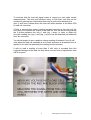
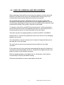
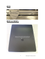
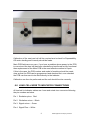
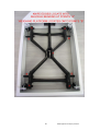
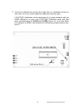
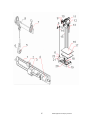
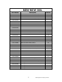
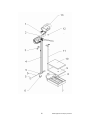
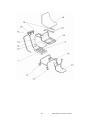
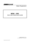
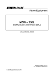
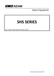
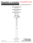
Adam Equipment
MDW MCW
Service Manual
Part No- 700660171 – rev C1 January 2012
Adam Equipment Company Ltd 2012
Adam Equipment Company Ltd 2012
CONTENTS
1.0
PRODUCT DESCRIPTION .................................................. 2
2.0
SPECIFICATION TABLE ..................................................... 3
3.0
TROUBLE SHOOTING GUIDE ............................................ 4
4.0
ERROR MESSAGES FOR MDW MCW .............................. 4
5.0
LOAD CELL REMOVAL AND REPLACEMENT ................... 6
6.0
LOAD CELL WIRE TO INDICATOR CONNECTIONS.......... 8
7.0
CALIBRATION FOR L MODELS........................................ 11
8.0
PARAMETERS .................................................................. 13
9.0
WARRANTY INFORMATION............................................. 20
1
Adam Equipment Company Ltd 2012
1.0 PRODUCT DESCRIPTION
The MDW series of health and fitness scales are available in 3 different
models.
The MDW 160M offering height and weight measurements up to 2.1 metres
and 160kg, this is a mechanical scale using a lever work system in the base
and a balancing beam type indication.
The MDW 250L offering height and weight measurement up to 2.1 metres and
250kg x 0.1kg.
The MDW 300L offering height and weight measurement up to 2.1 metres and
300kg x 0.05kg, as well as calculating your BMI following height entry into the
Indicator.
The MCW 300L is the wheelchair version and has the same functions and
specifications as the MDW 300L.
A single load cell is used for all 3 L models mounted to the weighing platform
and connected to a digital Indicator through a pillar via a cable
The digital Indicator used for both capacity models is very similar, the main
difference being that the 300kg capacity models use a different software
version and have rs 232 as standard.
All L type models have as standard a lead acid rechargeable battery fitted
internally to the Indicator.
2
Adam Equipment Company Ltd 2012
2.0
SPECIFICATION TABLE
MODEL
MDW
MDW
MDW
MCW
160M
250L
300L
300L
CAPACITY AND
DIVISION
160kg x 0.1kg
250kg x 0.1kg
300kg x 0.05kg
300kg x 0.05kg
3
BASE SIZE mm
275 x 375
275 x 375
275 x 375
450 x 450
Adam Equipment Company Ltd 2012
3.0 TROUBLE SHOOTING GUIDE
PROBLEM
Poor weighing
Performance
POSSIBLE CAUSES
Check for interference with the weighing platform
Check that the load cell is fully tightened or the lever
works are connected correctly
Check that the adjustable weights on the beam are in
the correct position
Check that the load cell cable is securely connected
and not damaged
Check that the overload stop is not incorrectly
adjusted or loose
Check that the product has good stability
Incorrect height
measuring
Height measuring device is loose
Height measuring device being operated incorrectly
4.0 ERROR MESSAGES FOR MDW MCW
ERROR
MESSAGE
_____
0
0_ _ _ _ _ _
_____
DESCRIPTION
POSSIBLE CAUSES
Zero point exceeds range
Zero point is under range
EEP.Er
CAL.Er
A/d exceeds the maximum
range
A/d is below the minimum
range
EEPROM error
Error when in calibration mode
Lo.bat
Internal battery voltage too low
FULL
The weight on the platform
exceeds the capacity of the
scale
Ad
Ad_ _ _ _ _
4
Load cell damage, main PCB fault,
Weight left on weighing platform
Load cell damage, main PCB fault,
Load cell connection problem
Improper calibration of the indicator,
Load cell damage, main PCB fault
Improper calibration of the indicator,
Load cell damage, main PCB fault
Processor failure
Incorrect operation of calibration,
Incorrect weight applied for calibration,
Weight unstable in calibration mode
Battery requires recharging or is faulty,
Power adaptor is faulty, main PCB fault
Person is too heavy,
Error in calibration
Adam Equipment Company Ltd 2012
To evaluate that the load cell signal output is correct you can make certain
measurements. The load cell functions using a 5Vdc input and this can be
checked by placing two individual probes from a multi meter between the
(exc +) and (exc-) cables where the load cell cable attaches to the Main PCB
or load cell connector.
If 5Vdc is present then power is being provided correctly to the load cell, the
next step is to measure the output of the load cell, this can be done by placing
the 2 probes between the (sig +) and (sig -) wires. In order to obtain an
accurate reading the (sig +) and (sig -) wires must be detached (de-soldered)
from the connector.
You should expect to see a positive voltage reading of between 0 and 2 milli
volts when the load cell assembly is at no load, and when a downward force is
applied to the load cell assembly the reading should increase.
If with no load a reading of more than 2 milli volts is recorded then this
suggests damage to the load cell may have occurred and a replacement load
cell is required.
5
Adam Equipment Company Ltd 2012
5.0 LOAD CELL REMOVAL AND REPLACEMENT
When replacing a load cell the correct type and capacity load cell should be
selected, once fitted it will need to be calibrated and checked, there is an
overload stop that should be adjusted to protect the load cell.
The overload stop should be adjusted to allow the minimum downward
movement of the load cell once full load is on the weighing platform, set the
overload stop by placing full load evenly onto the platform then adjust the stop
screw before locking it into position using the nut provided.
To replace a load cell on an MCW firstly unscrew the 4 x fixing screws that
secure the foot rest to the chair assembly and remove, then unscrew the 4 x
fixing screws that secure the chair assembly to the main frame.
This then exposes the weighing platform for both the MCW L and MDW L.
Unscrew the 4 x load cell fixing bolts that secure the load cell to the weighing
platform and remove.
Turn the platform over and unscrew the 4 x load cell fixing bolts that secure
the load cell to the main base.
The load cell can then be removed and disconnected from the cable
connector.
Fit the new load cell to the main base ensuring that the arrow for direction of
movement points downwards and the 4 x fixing bolts are tightened well, then
solder the wires to the Indicator connector.
Refit the weighing platform and tighten the 4 x fixing bolts, check that the
overload stop is correctly set before testing.
Follow the steps below to remove and replace a load cell.
6
Adam Equipment Company Ltd 2012
MCW
MCW and MDW L
7
Adam Equipment Company Ltd 2012
Calibration of the new load cell will be required and a check for Repeatability,
Off centre loading and Linearity should be made.
Main PCB faults are very rare, if you have a problem where power to the PCB
is correct and the load cell has been checked and confirmed as fully functional
then replacement of the Main PCB is the most effective method of repair.
If this is the case, the PCB number and model of machine should be made
clear so that the PCB can be programmed and checked first, once checked
the PCB can then sent to be fitted directly to the Indicator.
Calibration can then be performed and the unit should function correctly
6.0 LOAD CELL WIRE TO INDICATOR CONNECTIONS
All load cell to Indicator cables are 4 core and wired via a connector following
the pin numbers as below.
Pin 1 Excitation plus+ Red
Pin 2 Excitation minus – Black
Pin 3 Signal minus – Green
Pin 4 Signal Plus + White
8
Adam Equipment Company Ltd 2012
The MDW 160M relies on a lever system in the base using bearings and knife
edges to transfer the force applied to the weighing platform to a central
column.
Connected to the top of this column is a beam with a pivoting knife edge,
sliding the poise weights along this beam to a graduated weight marking
balances the beam when a weight is applied to the weighing platform, the
marking is then observed to indicate your weight reading.
To calibrate the poise weights you require a load to be added to the weighing
platform equal to the maximum marked position on the beam for that poise
weight, move the poise weight to the marked position and the beam should
balance, if you do not find an accurate balance then add or remove mass from
the poise weight.
Each poise weight should be adjusted individually using its own beam.
The zero poise weight should only be adjusted so that a zero point can easily
be achieved with the zero screw, this poise weight has no direct effect on the
calibration of the MDW.
The knife edges in the base need to be located into the shackles that contains
the bearings, if positioned correctly the top pan should always swing freely
when moved, if there is any sign of a stiff or uneasy movement then this could
point to the base lever works being out of position.
To observe the lever works correctly you need to have access from the
underside, you will see 4 x platform retaining stops, these are square metal
plates held on by a screw that need to be removed for the weighing platform
to be detached, once detached you can view the lever works from above.
At this point you can observe all of the connecting knife edges and bearings to
ensure they are in position, the lever work system should swing and move
easily when correct
9
Adam Equipment Company Ltd 2012
10
Adam Equipment Company Ltd 2012
7.0 CALIBRATION FOR L MODELS
Before calibrating the scale, you should ensure that you have a suitable
known qualified weight for calibration.
1. When in normal weighing mode with the scale at zero press and hold
down the [TARE] and [ON / OFF] keys to enter the calibration mode.
2. If the calibration switch is in the off position on the main PCB inside the
scale, the indicator will show “CAL OFF” and then exit this mode, if so
remove the rear cover of the Indicator and place the jumper in the “ON”
position. If the indicator shows “CAL-?”, the scale is ready for calibration.
3. When the indicator shows “CAL-?”, press the [TARE] key to confirm and
go to next step.
4. When ‘0.0’ is displayed the scale will begin to calibrate the scale’s zeropoint. Ensure that there is no load or weight on the scale’s platform. Press
the [TARE] key to confirm.
5. A few seconds after the [TARE] key has been pressed in step 4 the scale
will show “300.0” and the kg LED will be illuminated, or “600.0” and the lb
LED will be illuminated depending on which unit you have chosen, this is
the default calibration weight from the factory. Press the [UNIT] key to
select the calibration weight unit that you want to calibrate in. Press the
[Print/Hold] key to choose a different calibration weight value (50kg,
100kg, 150kg, 200kg, 250kg, 300kg or 100lb, 200lb, 300lb, 400lb, 500lb,
600lb); Then put on the weight that you selected and press the [TARE]
key to confirm the chosen standard weight that was selected. The
displayed data will flash on the display and if the scale accepts the
calibration data it will calculate and store the information into the
EEPROM. If an error has occurred, the scale will display “CAL. Er” and
return back to step 4 for re-calibration. If the loaded weight is not within
the range of 95% to 105% of the weight value you selected the scale will
not calibrate but display “CAL. Er” and return back to step 4 for recalibration. )
6. If zero cannot be calibrated at step 4 the ADC needs to be checked and
possibly adjusted. Press and hold the [ON/OFF] and [PRINT/HOLD] keys
for three seconds after powering up. The display should show “code” then
the raw ADC counts. The potentiometer VR1 can be adjusted until the
counts with no load are between 20,000 and 30,000. For a working unit
the ADC counts should increment approx 35,000 for a 50kg calibration
mass loaded. VR1 is situated on the main PCB, please see below
diagram.
11
Adam Equipment Company Ltd 2012
7. Check the calibration by putting the weight that you calibrated at back on
the scale, if it is not correct repeat the calibration process again.
A FACTORY Calibration can be performed if you have problems with the
USER calibration, to carry out a FACTORY Calibration press and hold
down simultaneously the [UNIT] and [TARE] buttons for 3 seconds whilst
the reading is at ZERO, from this point on follow the procedure above from
point 2.
12
Adam Equipment Company Ltd 2012
8.0 PARAMETERS
This indicator has 4 parameter settings that can be selected.
1. When the scale is in normal weighing mode, press and hold down the [ON
/ OFF] key and the [UNIT] key for 3 seconds until ‘Setup’ is shown on the
display.
2. When in the ‘Setup’ mode, press the [Print/Hold] key to change the
flashing digits, and [TARE] key to confirm the flashing digits and move to
the next parameter setting. Press the [ON / OFF] key to exit the set up
mode.
3. Parameters setting summary:
Parameter
Available Factory
Settings Setting
A.o.t.
00-15
05
P.H.
0,1,2
1
H.t
0-4
0
S.F.
0-3
0
Setting
Auto-off time:
No auto-off = 00.
01-15 minutes auto-off time.
Print and Hold Button function
0 = Only Print Function
1 = Only Hold Function
2 = both HOLD and PRINT function
To PRINT, push button once
To HOLD, push button down for 3 seconds
Hold time:
0 = no time limit.
1 = 10 seconds
2 = 30 seconds
3 = 60 seconds
4 = 120 seconds
RS 232 Control
0 = No RS232 Function.
1 = Continuously outputs display data.
2 = Outputs display data when PRINT is pressed
3 = Bi-directional communication (the scale
receives and executes commands from the
HOST device)
13
Adam Equipment Company Ltd 2012
9.0 PARTS LISTS
MDW 160M
Part number
Description
Item No
7.00.1.0.0184
7.00.1.0.0134
7.00.1.0.0135
7.00.1.0.0136
WEIGHING RULER
ZERO BALANCE WEIGHT
1
2
3
4
7.00.1.0.0132
KNIFE EDGE BEARING FOR BOTTOM OF
CONNECTING ROD
5
7.00.1.4.0005
7.00.1.2.0001
7.00.1.0.0130
7.00.1.2.0002
7.00.2.3.0004
7.00.1.2.0003
7.00.1.0.0137
7.00.2.0.0047
7.00.1.0.0129
7.00.1.0.0142
7.00.2.0.0046
7.00.1.0.0133
7.00.1.0.0139
7.00.1.0.0141
7.00.1.0.0140
7.00.1.0.0138
7.00.1.0.0128
7.00.3.0.0011
SMALL POISE WEIGHT
LARGE POISE WEIGHT
CONNECTING ROD HOOK
PIVOT
CONNECTING ROD LEVER
BRACKET
PLASTIC COVER
EYE LOOP
PILLAR HEAD(T SHAPE)
HEIGHT ROD
BASE TO INDICATOR CONNECTING ROD
PILLAR
PLASTIC PLATFORM COVER
METAL PLATFORM
CENTRE LINK
LONG LEVER
SHORT LEVER
CORNER LINK
BASE FRAME
6
7
8
9
10
11
12
13
14
15
16
17
18
19
20
21
22
COMPLETE PACKAGING SET
14
Adam Equipment Company Ltd 2012
15
Adam Equipment Company Ltd 2012
MDW 250L
Part number
Description
Item No
7.00.1.0.0143
7.00.1.0.0144
7.00.1.0.0145
7.00.2.0.0049
7.00.1.0.0146
3.02.4.0.5088
7.00.5.6.0015
7.00.4.0.0037
7.00.1.0.0147
7.00.1.0.0148
7.00.1.2.0004
7.00.4.0.0073
7.00.4.0.0074
7.00.3.0.0012
3.02.4.0.9156
3.02.4.0.9160
3.02.4.0.9159
3.02.4.0.9157
3.02.4.0.9158
7.00.2.0.0048
BASE FRAME
1
2
3
4
5
6
7
8
9
10
11
12
13
HEIGHT ROD HOLDER
METAL PLATFORM
PLASTIC PLATFORM COVER
210cm HEIGHT ROD
6V dc 4.5ah BATTERY
FASCIA
MAIN / DISPLAY PCB- STATE WHICH REVISION
LOAD CELL LCT LAE-A- 350kg cell
PILLAR
PILLAR HOLDER
ON/OFF SWITCH
POWER IN SOCKET
COMPLETE PACKAGING SET
12v DC @800ma ADAPTOR-UK
12v DC @800ma ADAPTOR-USA
12v DC @800ma ADAPTOR-OZ
12v DC @800ma ADAPTOR-EURO
12v DC @800ma ADAPTOR-SA
INDICATOR ASSEMBLY
16
Adam Equipment Company Ltd 2012
MDW MCW 300L
Part number
Description
Item No
7.00.1.0.0247
MDW 300L HEIGHT ROD SUPPORT (UPPER)
3
7.00.1.0.0248
MDW 300L 210cm SQUARE HEIGHT ROD
4
7.00.2.0.0078
MDW 300L WHEEL ASSEMBLY
5
7.00.1.0.0258
MDW 300L HEIGHT ROD BRACKET (LOWER)
6
7.00.1.0.0145
MDW 300L METAL PLATFORM
9
7.00.2.0.0049
7.00.1.0.0249
MDW 300L PLASTIC PLATFORM COVER
10
MDW 300L PILLAR
11
7.00.2.0.0077
MDW 300L FASCIA
13
7.00.3.0.0020
MDW 300L COMPLETE PACKAGING SET
7.00.0.0.0133
MDW 300L INDICATOR ASSEMBLY
7.00.0.0.0126
MCW 300L CHAIR
14
7.00.2.0.0074
MCW 300L ARM REST (PLASTIC PART ONLY x 2)
15
7.00.2.0.0075
MCW 300L FASCIA
16
7.00.0.0.0127
MCW 300L INDICATOR ASSEMBLY
17
7.00.1.0.0245
MCW 300L PILLAR
18
7.00.1.0.0259
MCW 300L HANDLE
19
7.00.1.0.0243
MCW 300L METAL WEIGHING PLATE
20
7.00.2.0.0076
MCW 300L WHEEL WITH BRAKE (REAR)
21
7.00.1.0.0260
MCW 300L WHEEL SWIVEL (FRONT)
22
7.00.2.0.0073
MCW 300L FOOT REST FRAME ASSEMBLY
23
7.00.1.0.0261
MCW 300L WHEEL FRAME (EXC WHEELS)
24
7.00.1.0.0241
MCW 300L CHAIR FRAME ASSEMBLY
25
7.00.1.0.0262
MCW 300L ARM REST (METAL PART x 2)
26
7.00.3.0.0019
MCW 300L COMPLETE PACKAGING SET
7.00.4.0.0066
MDW MCW 300L MAIN / DISPLAY PCB- WITH RS 232
1
3.02.4.0.5088
MDW MCW 300L BATTERY
2
7.00.1.0.0246
MDW MCW 300L BASE FRAME
7
7.00.1.0.0244
MDW MCW 300L LOAD CELL 300kg cell
8
7.00.4.0.0064
MDW MCW 300L ON/OFF SWITCH
7.00.4.0.0065
MDW MCW 300L LOAD CELL CONNECTOR (2 PARTS)
3.02.4.0.9156
12v DC @800ma ADAPTOR-UK
3.02.4.0.9160
12v DC @800ma ADAPTOR-USA
3.02.4.0.9159
12v DC @800ma ADAPTOR-OZ
3.02.4.0.9157
12v DC @800ma ADAPTOR-EURO
3.02.4.0.9158
12v DC @800ma ADAPTOR-SA
17
12
Adam Equipment Company Ltd 2012
18
Adam Equipment Company Ltd 2012
19
Adam Equipment Company Ltd 2012
10.0 WARRANTY INFORMATION
Adam Equipment offers Limited Warranty (Parts and Labour) for the components failed
due to defects in materials or workmanship. Warranty starts from the date of delivery.
During the warranty period, should any repairs be necessary, the purchaser must
inform its supplier or Adam Equipment Company. The company or its authorised
Technician reserves the right to repair or replace the components at any of its
workshops depending on the severity of the problems. However, any freight involved
in sending the faulty units or parts to the service centre should be borne by the
purchaser.
The warranty will cease to operate if the equipment is not returned in the original
packaging and with correct documentation for a claim to be processed. All claims are at
the sole discretion of Adam Equipment.
This warranty does not cover equipment where defects or poor performance is due to
misuse, accidental damage, exposure to radioactive or corrosive materials, negligence,
faulty installation, unauthorised modifications or attempted repair or failure to
observe the requirements and recommendations as given in this User Manual.
Additionally rechargeable batteries (where supplied) are not covered under warranty.
Repairs carried out under the warranty does not extend the warranty period.
Components removed during the warranty repairs become the company property.
The statutory right of the purchaser is not affected by this warranty. The terms of this
warranty is governed by the UK law. For complete details on Warranty Information, see
the terms and conditions of sale available on our web-site.
20
Adam Equipment Company Ltd 2012
Manufacturer’s Declaration of Conformity
This product has been manufactured in accordance with the harmonised European
standards, following the provisions of the below stated directives:
Electro Magnetic Compatibility Directive 2004/108/EC
Low Voltage Directive 2006/95/EC
Adam Equipment Co. Ltd.
Bond Avenue, Denbigh East
Milton Keynes, MK1 1SW
United Kingdom
FCC COMPLIANCE
This equipment has been tested and found to comply with the limits for a Class A digital device, pursuant
to Part 15 of the FCC Rules. These limits are designed to provide reasonable protection against harmful
interference when the equipment is operated in a commercial environment. The equipment generates,
uses, and can radiate radio frequency energy and, if not installed and used in accordance with the
instruction manual, may cause harmful interference to radio communications. Operation of this
equipment in a residential area is likely to cause harmful interference in which case the user will be
required to correct the interference at his own expense.
Shielded interconnect cables must be employed with this equipment to insure compliance with the
pertinent RF emission limits governing this device.
Changes or modifications not expressly approved by Adam Equipment could void the user's authority to
operate the equipment.
WEEE COMPLIANCE
Any Electrical or Electronic Equipment (EEE) component or assembly of parts intended to be
incorporated into EEE devices as defined by European Directive 2002/95/EEC must be recycled or
disposed using techniques that do not introduce hazardous substances harmful to our health or the
environment as listed in Directive 2002/95/EC or amending legislation. Battery disposal in Landfill Sites is
more regulated since July 2002 by regulation 9 of the Landfill (England and Wales) Regulations 2002 and
Hazardous Waste Regulations 2005. Battery recycling has become topical and the Waste Electrical and
Electronic Equipment (WEEE) Regulations are set to impose targets for recycling.
Adam Equipment Company Ltd 2012
ADAM EQUIPMENT is an ISO 9001:2008 certified global company with more than
35 years experience in the production and sale of electronic weighing equipment.
Adam products are predominantly designed for the Laboratory, Educational, Health
and Fitness, retail and Industrial Segments. The product range can be described as
follows:
-Analytical and Precision Balances
-Compact and Portable Balances
-High Capacity Balances
-Moisture analysers / balances
-Mechanical Scales
-Counting Scales
-Digital Weighing/Check-weighing Scales
-High performance Platform Scales
-Crane scales
-Health and Fitness Scales
-Retail Scales for Price computing
For a complete listing of all Adam products visit our website at
www.adamequipment.com
© Copyright by Adam Equipment Co. Ltd. All rights reserved. No part of this publication may be reprinted or
translated in any form or by any means without the prior permission of Adam Equipment.
Adam Equipment reserves the right to make changes to the technology, features, specifications and design of
the equipment without notice.
All information contained within this publication is to the best of our knowledge timely, complete and accurate
when issued. However, we are not responsible for misinterpretations which may result from the reading of
this material.
The latest version of this publication can be found on our Website.
www.adamequipment.com
Adam Equipment Company Ltd 2012