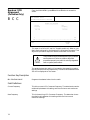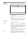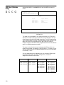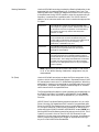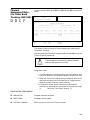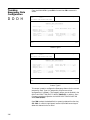
1
ASTRO™
Radio Platform
Radio Service Software
User’s Guide
Software Part Number: CVN-6085A
© 1996 Motorola, Inc., Radio Products Group
8000 W. Sunrise Blvd., Ft. Lauderdale, FL 33322
Printed in U.S.A. 10/96. All Rights Reserved.
68-81098E85-O
Computer Software Copyrights
The Motorola® equipment described in this manual may include copyrighted Motorola computer
programs stored in semiconductor memories or other media. Laws in the United States and other
countries preserve for Motorola certain exclusive rights for copyrighted computer programs,
including the exclusive right to copy or reproduce in any form the copyrighted computer program.
Accordingly, any copyrighted Motorola computer programs contained in the Motorola equipment
described in this manual may not be copied or reproduced in any manner without the express
permission of Motorola. Furthermore, the purchase of Motorola equipment shall not be deemed to
grant either directly or by implication, estoppel or otherwise, any license under the copyrights,
patents or patent applications of Motorola, except for the normal non-exclusive, royalty-free license
to use that arises by operation of law in the sales of a product.
Licensing Restrictions
The installation program used to install ASTRO™ Radio Service Software, INSTALL, is licensed
software provided by Knowledge Dynamics Corp., P.O. Box 1558, Canyon Lake, Texas 78130-1558
(USA). INSTALL is Copyright (c) 1987-1992 by Knowledge Dynamics Corp. which reserves all
copyright protection worldwide. INSTALL is provided to you for the exclusive purpose of installing
ASTRO Radio Service Software. Motorola is exclusively responsible for the support of ASTRO Radio
Service Software, including support during the installation phase. In no event will Knowledge
Dynamics Corp. provide any technical support for ASTRO Radio Service Software.
Trademarks
, Motorola, PAC-RT, and Private-Line are registered trademarks of Motorola, Inc.
ASTRO, Call Alert, Channel Scan, Conventional ASTRO, Digital Private-Line, FLASHport, HearClear,
MDC-1200, Quik-Call, Quik-Call II, SABER, SABER SI, Secure Clear, SECURENET, Sel Cal, Single Tone,
SMARTNET, SMARTNET ASTRO, SMARTNET DATA, SmartZone, Stat-Alert, and VRM-500 are
trademarks of Motorola, Inc.
PC XT and Personal Computer AT are trademarks of IBM Corp.
MS-DOS and Windows are trademarks of Microsoft Corp.
Copyright© Motorola 1990-1996. Printed in USA. All rights reserved.
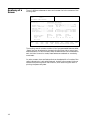
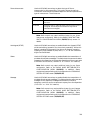
Foreword
This edition of the ASTRO™ Radio Service Software (RSS) user’s guide contains revisions and updates made
in support of all ASTRO RSS bearing the Software Part Number 6085A, particularly ASTRO RSS version
R05.00.00. Although the new RSS contains other changes, this update is primarily driven by the
introduction of ASTRO System Release 3.0 and Motorola’s new ASTRO Digital Portable radio: the XTS
3000.
Note: Since the ASTRO SABER™ and ASTRO XTS 3000 classes of radio are internally and
ergonomically different models, they are not cross-clonable. In other words, the ASTRO Portable RSS
CANNOT be used to clone a SABER archive into a XTS 3000 and vice-versa.
Below is a summary of the primary ASTRO Radio Service Software (RSS) enhancements and ASTRO radio
feature support introduced in this new release of Motorola ASTRO (Portable/Mobile) RSS. Note that some
of these features and enhancements are available on a Portable versus Mobile radio basis while others are
common to both ASTRO radio types. Please also note that, with the exception of any identified RSS
software enhancements, many ASTRO RSS field and screen introductions typically allow the
programming of radio options. This means that the visibility of these fields in the RSS will depend on the
capability of the particular ASTRO being programmed. Please consult your radio manual and/or refer to
the appropriate sections of this user’s manual for a detailed description of the respective radio features.
ASTRO Portable RSS only:
ASTRO XTS 3000 radio models support.
ASTRO Mobile RSS only:
Support of Auxiliary Siren Switch as a Vehicle Interface Port (VIP) input.
Support of External Transmit Attenuator as a Vehicle Interface Port (VIP) output.
Improved Vehicular Repeater System–Expanded Protocol (VRS-EP).
Programmable Self-Test Alert Tone.
Support of Direct Status, Message and Mode on DEKs.
ASTRO Portable AND Mobile RSS:
Fully programmable MDC System Ack Pretime.
Programmable Trunking Transmit Deviation level.
Digital Common Air Interface (CAI) Operation.
ASTRO Conventional Talkgroups.
vii
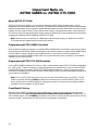
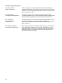
Important Note on
ASTRO SABER vs. ASTRO XTS 3000
About ASTRO XTS 3000
ASTRO XTS 3000 is an addition to the family of Motorola ASTRO Digital Portable radios. Like its
predecessor the ASTRO SABER radio, the ASTRO XTS 3000 can be programmed using the ASTRO Portable
Radio Service Software. Only a handful of subtle RSS feature field and screen differences are visibly evident
between the two types of radios. These variations are noted in the appropriate screen views captured in
this manual. Most of these variations are simply a result of differences in radio display and other physical
characteristics between ASTRO SABER and ASTRO XTS 3000.
Note: Please consult your ASTRO XTS 3000 radio User’s Manual directly for detailed information
on the features and capabilities of the new radio product.
Programming ASTRO SABER Portables
As far as general usage is concerned, the revised ASTRO Portable RSS is no different from the one used to
program pre-existing ASTRO SABER Portable radios. You should be able to program ASTRO SABER radios
using this RSS just as you did with previous RSS versions. If you have no previous experience in
programming an ASTRO SABER Portable radio, this manual will serve as an introduction and detailed
reference on the use of this RSS.
Programming ASTRO XTS 3000 Portables
Unlike ASTRO SABER models which have an “H04” model number prefix, ASTRO XTS 3000 models bear
the “H09” prefix. There are, however, no special operations to be performed in order to use the ASTRO
Portable RSS software to program ASTRO XTS 3000 models. Proceed with reading, programming and
writing to the codeplug as you usually do with ASTRO SABER models, consulting the appropriate sections
of this manual as necessary.
Note: First time ASTRO RSS users should note that like the ASTRO SABER model, the ASTRO XTS 3000
model is a portable radio which MUST be used with the Portable version of the ASTRO RSS. Again, if you
are not familiar with the ASTRO RSS at all, reading this manual in its entirety should help you better
understand how to program an ASTRO radio.
Cross-Model Cloning
Although both ASTRO XTS 3000 and ASTRO SABER radio models can be configured using the same
(ASTRO Portable) RSS, they inherently belong to different radio model categories. Consequently, an
ASTRO SABER radio or archive CANNOT be cloned into an ASTRO XTS 3000 radio and vice versa. Such cloning
scenarios are NOT supported by the RSS and will be unsuccessful if attempted.
viii
Table of Contents
➠
1 - Getting Started . . . . . . . . . . . . . . . . . . . . . . . . . . . . . . . . . . . . . . . . . . . . . . . . . . . . . . . . . . . .7
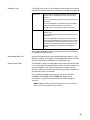
Prerequisites . . . . . . . . . . . . . . . . . . . . . . . . . . . . . . . . . . . . . . . . . . . . . . . . . . . . . . . . . . . . . . . . . . . . . . 8
Using This Manual . . . . . . . . . . . . . . . . . . . . . . . . . . . . . . . . . . . . . . . . . . . . . . . . . . . . . . . . . . . . . . . . . 9
Assembling The Hardware . . . . . . . . . . . . . . . . . . . . . . . . . . . . . . . . . . . . . . . . . . . . . . . . . . . . . . . . . . 10
What’s On The RSS Diskettes . . . . . . . . . . . . . . . . . . . . . . . . . . . . . . . . . . . . . . . . . . . . . . . . . . . . . . . . 12
Installing The RSS. . . . . . . . . . . . . . . . . . . . . . . . . . . . . . . . . . . . . . . . . . . . . . . . . . . . . . . . . . . . . . . . . 12
The Banner Screen . . . . . . . . . . . . . . . . . . . . . . . . . . . . . . . . . . . . . . . . . . . . . . . . . . . . . . . . . . . . . . . . 15
Anatomy of a Menu . . . . . . . . . . . . . . . . . . . . . . . . . . . . . . . . . . . . . . . . . . . . . . . . . . . . . . . . . . . . . . . 16
Navigating Through The RSS Menus . . . . . . . . . . . . . . . . . . . . . . . . . . . . . . . . . . . . . . . . . . . . . . . . . . 17
Anatomy of a Screen . . . . . . . . . . . . . . . . . . . . . . . . . . . . . . . . . . . . . . . . . . . . . . . . . . . . . . . . . . . . . . 18
Complete Menu Mapping at a Glance. . . . . . . . . . . . . . . . . . . . . . . . . . . . . . . . . . . . . . . . . . . . . . . . . 19
Changing A Field Value . . . . . . . . . . . . . . . . . . . . . . . . . . . . . . . . . . . . . . . . . . . . . . . . . . . . . . . . . . . . 22
Configuring Computer Defaults from the RSS . . . . . . . . . . . . . . . . . . . . . . . . . . . . . . . . . . . . . . . . . . 23
Retrieving RSS Version & Parts Information . . . . . . . . . . . . . . . . . . . . . . . . . . . . . . . . . . . . . . . . . . . . 25
Exiting the RSS . . . . . . . . . . . . . . . . . . . . . . . . . . . . . . . . . . . . . . . . . . . . . . . . . . . . . . . . . . . . . . . . . . . 25
Main Menu . . . . . . . . . . . . . . . . . . . . . . . . . . . . . . . . . . . . . . . . . . . . . . . . . . . . . . . . . . . . . . . . . . . . . . 26
Service Software Configuration . . . . . . . . . . . . . . . . . . . . . . . . . . . . . . . . . . . . . . . . . . . . . . . . . . . . . . 28
Configure Paths and Port . . . . . . . . . . . . . . . . . . . . . . . . . . . . . . . . . . . . . . . . . . . . . . . . . . . . . . . . . . . 29
Setting Screen Colors . . . . . . . . . . . . . . . . . . . . . . . . . . . . . . . . . . . . . . . . . . . . . . . . . . . . . . . . . . . . . . 32
2 - Basic Radio
Programming Tutorial . . . . . . . . . . . . . . . . . . . . . . . . . . . . . . . . . . . . . . . . . . . . . . . . . . . . . . .35
Programming a Basic 16-Channel ASTRO Conventional Radio . . . . . . . . . . . . . . . . . . . . . . . . . . . . . 35
Desired Features . . . . . . . . . . . . . . . . . . . . . . . . . . . . . . . . . . . . . . . . . . . . . . . . . . . . . . . . . . . . . . . . 35
Major Decisions Involved . . . . . . . . . . . . . . . . . . . . . . . . . . . . . . . . . . . . . . . . . . . . . . . . . . . . . . . . 36
High-Level Programming Flow . . . . . . . . . . . . . . . . . . . . . . . . . . . . . . . . . . . . . . . . . . . . . . . . . . . . 36
ASTRO Button/Switch/Menu Item Defaults . . . . . . . . . . . . . . . . . . . . . . . . . . . . . . . . . . . . . . . . . . 37
Step-by-Step Programming Instructions . . . . . . . . . . . . . . . . . . . . . . . . . . . . . . . . . . . . . . . . . . . . . 41
Programming a Basic ASTRO Trunked Radio. . . . . . . . . . . . . . . . . . . . . . . . . . . . . . . . . . . . . . . . . . . . 45
Desired Features . . . . . . . . . . . . . . . . . . . . . . . . . . . . . . . . . . . . . . . . . . . . . . . . . . . . . . . . . . . . . . . . 45
Major Decisions Involved . . . . . . . . . . . . . . . . . . . . . . . . . . . . . . . . . . . . . . . . . . . . . . . . . . . . . . . . 45
High-Level Programming Flow . . . . . . . . . . . . . . . . . . . . . . . . . . . . . . . . . . . . . . . . . . . . . . . . . . . . 45
Step-by-Step Programming Instructions . . . . . . . . . . . . . . . . . . . . . . . . . . . . . . . . . . . . . . . . . . . . . 46
ASTRO SABER I Radio Button/Switch/Menu Item Defaults . . . . . . . . . . . . . . . . . . . . . . . . . . . . . . 46
ASTRO XTS 3000 I Radio Button/Switch/Menu Item Defaults . . . . . . . . . . . . . . . . . . . . . . . . . . . . 46
ASTRO SABER II Radio Button/Switch/Menu Item Defaults. . . . . . . . . . . . . . . . . . . . . . . . . . . . . . 47
ASTRO SABER III Radio Button/Switch/Menu Item Defaults . . . . . . . . . . . . . . . . . . . . . . . . . . . . . 49
ASTRO XTS 3000 III Radio Button/Switch/Menu Item Defaults . . . . . . . . . . . . . . . . . . . . . . . . . . 49
ASTRO Mobile Radio Conventional/Trunking Button Locations . . . . . . . . . . . . . . . . . . . . . . . . . . . . 50
Cloning Radios . . . . . . . . . . . . . . . . . . . . . . . . . . . . . . . . . . . . . . . . . . . . . . . . . . . . . . . . . . . . . . . . . . . 57
Exit the RSS. . . . . . . . . . . . . . . . . . . . . . . . . . . . . . . . . . . . . . . . . . . . . . . . . . . . . . . . . . . . . . . . . . . . . . 58
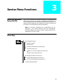
3 - Service Menu Functions . . . . . . . . . . . . . . . . . . . . . . . . . . . . . . . . . . . . . . . . . . . . . . . . . . . .59
Servicing the Radio Using the RSS . . . . . . . . . . . . . . . . . . . . . . . . . . . . . . . . . . . . . . . . . . . . . . . . . . . . 59
Menu Map . . . . . . . . . . . . . . . . . . . . . . . . . . . . . . . . . . . . . . . . . . . . . . . . . . . . . . . . . . . . . . . . . . . . . . 59
Service Menu . . . . . . . . . . . . . . . . . . . . . . . . . . . . . . . . . . . . . . . . . . . . . . . . . . . . . . . . . . . . . . . . . . . . 60
Controller Board Initialization. . . . . . . . . . . . . . . . . . . . . . . . . . . . . . . . . . . . . . . . . . . . . . . . . . . . . . . 62
Transmitter Alignment Menu . . . . . . . . . . . . . . . . . . . . . . . . . . . . . . . . . . . . . . . . . . . . . . . . . . . . . . . 64
i
Reference Oscillator Alignment . . . . . . . . . . . . . . . . . . . . . . . . . . . . . . . . . . . . . . . . . . . . . . . . . . . . . . 66
Transmit Power Alignment . . . . . . . . . . . . . . . . . . . . . . . . . . . . . . . . . . . . . . . . . . . . . . . . . . . . . . . . . 67
Transmit Deviation Balance (Compensation) Alignment . . . . . . . . . . . . . . . . . . . . . . . . . . . . . . . . . . 69
Transmit Deviation Limit (Portables Only) . . . . . . . . . . . . . . . . . . . . . . . . . . . . . . . . . . . . . . . . . . . . . 71
Transmit Current Limit Alignment (Mobiles Only) . . . . . . . . . . . . . . . . . . . . . . . . . . . . . . . . . . . . . . 72
Receive Alignment Menu (Portables Only) . . . . . . . . . . . . . . . . . . . . . . . . . . . . . . . . . . . . . . . . . . . . . 74
Front-End Filter Alignment (Portables Only). . . . . . . . . . . . . . . . . . . . . . . . . . . . . . . . . . . . . . . . . . . . 75
Receiver VCO Alignment (Portables Only) . . . . . . . . . . . . . . . . . . . . . . . . . . . . . . . . . . . . . . . . . . . . . 76
4 - Get/Save/Program Menu Functions . . . . . . . . . . . . . . . . . . . . . . . . . . . . . . . . . . . . . . . . . . 77
Menu Map . . . . . . . . . . . . . . . . . . . . . . . . . . . . . . . . . . . . . . . . . . . . . . . . . . . . . . . . . . . . . . . . . . . . . . 77
Get/Save/Program Menu . . . . . . . . . . . . . . . . . . . . . . . . . . . . . . . . . . . . . . . . . . . . . . . . . . . . . . . . . . . 78
Reading Codeplug Data From Radio (Requires RIB) . . . . . . . . . . . . . . . . . . . . . . . . . . . . . . . . . . . . . . 80
Get Codeplug Data From Archive File . . . . . . . . . . . . . . . . . . . . . . . . . . . . . . . . . . . . . . . . . . . . . . . . . 81
Clone Radio . . . . . . . . . . . . . . . . . . . . . . . . . . . . . . . . . . . . . . . . . . . . . . . . . . . . . . . . . . . . . . . . . . . . . 82
MDC Data Cloning. . . . . . . . . . . . . . . . . . . . . . . . . . . . . . . . . . . . . . . . . . . . . . . . . . . . . . . . . . . . . . . . 85
ASTRO ID . . . . . . . . . . . . . . . . . . . . . . . . . . . . . . . . . . . . . . . . . . . . . . . . . . . . . . . . . . . . . . . . . . . . . . . 87
MODAT. . . . . . . . . . . . . . . . . . . . . . . . . . . . . . . . . . . . . . . . . . . . . . . . . . . . . . . . . . . . . . . . . . . . . . . . . 88
Saving Codeplug Data to an Archive File. . . . . . . . . . . . . . . . . . . . . . . . . . . . . . . . . . . . . . . . . . . . . . . 89
Programming the Radio Codeplug (Requires RIB) . . . . . . . . . . . . . . . . . . . . . . . . . . . . . . . . . . . . . . . . 91
Programming History . . . . . . . . . . . . . . . . . . . . . . . . . . . . . . . . . . . . . . . . . . . . . . . . . . . . . . . . . . . . . . 92
5 - Change/View Menu Functions. . . . . . . . . . . . . . . . . . . . . . . . . . . . . . . . . . . . . . . . . . . . . . . 95
Menu Map . . . . . . . . . . . . . . . . . . . . . . . . . . . . . . . . . . . . . . . . . . . . . . . . . . . . . . . . . . . . . . . . . . . . . . 95
Change/View Menu . . . . . . . . . . . . . . . . . . . . . . . . . . . . . . . . . . . . . . . . . . . . . . . . . . . . . . . . . . . . . . . 97
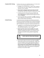
Radio Wide Configuration Menu. . . . . . . . . . . . . . . . . . . . . . . . . . . . . . . . . . . . . . . . . . . . . . . . . . . . . 99
Radio Wide Options . . . . . . . . . . . . . . . . . . . . . . . . . . . . . . . . . . . . . . . . . . . . . . . . . . . . . . . . . . . . . . 101
Radio Wide Secure Options . . . . . . . . . . . . . . . . . . . . . . . . . . . . . . . . . . . . . . . . . . . . . . . . . . . . . . . . 106
Hardware Encryption Multikey Options. . . . . . . . . . . . . . . . . . . . . . . . . . . . . . . . . . . . . . . . . . . . . . 109
Software Encryption Multikey Options. . . . . . . . . . . . . . . . . . . . . . . . . . . . . . . . . . . . . . . . . . . . . . . 111
Software Key Entry Menu . . . . . . . . . . . . . . . . . . . . . . . . . . . . . . . . . . . . . . . . . . . . . . . . . . . . . . . . . . 112
More Multikey Parameters . . . . . . . . . . . . . . . . . . . . . . . . . . . . . . . . . . . . . . . . . . . . . . . . . . . . . . . . . 113
OTAR Options . . . . . . . . . . . . . . . . . . . . . . . . . . . . . . . . . . . . . . . . . . . . . . . . . . . . . . . . . . . . . . . . . . 115
Radio Wide Emergency Options . . . . . . . . . . . . . . . . . . . . . . . . . . . . . . . . . . . . . . . . . . . . . . . . . . . . 118
More Radio Wide Options . . . . . . . . . . . . . . . . . . . . . . . . . . . . . . . . . . . . . . . . . . . . . . . . . . . . . . . . . 120
Radio Wide Features Configuration Menu. . . . . . . . . . . . . . . . . . . . . . . . . . . . . . . . . . . . . . . . . . . . . 123
Radio Wide Button Configuration (Mobiles Only) . . . . . . . . . . . . . . . . . . . . . . . . . . . . . . . . . . . . . . 125
Radio Wide Button Configuration (Portables Only) . . . . . . . . . . . . . . . . . . . . . . . . . . . . . . . . . . . . . 128
Hand-Held Control Button Configuration (ASTRO SABER Portables Only) . . . . . . . . . . . . . . . . . . . 132
Radio Wide Switch Configuration (Portables Only) . . . . . . . . . . . . . . . . . . . . . . . . . . . . . . . . . . . . . 136
Radio Wide Switch Configuration (Mobiles Only) . . . . . . . . . . . . . . . . . . . . . . . . . . . . . . . . . . . . . . 140
Radio Wide Menu Item Configuration . . . . . . . . . . . . . . . . . . . . . . . . . . . . . . . . . . . . . . . . . . . . . . . 141
DEK Button Configuration (Mobiles Only) . . . . . . . . . . . . . . . . . . . . . . . . . . . . . . . . . . . . . . . . . . . . 146
VIP In (Mobiles Only). . . . . . . . . . . . . . . . . . . . . . . . . . . . . . . . . . . . . . . . . . . . . . . . . . . . . . . . . . . . . 149
VIP Out (Mobiles Only) . . . . . . . . . . . . . . . . . . . . . . . . . . . . . . . . . . . . . . . . . . . . . . . . . . . . . . . . . . . 150
Phone Configuration . . . . . . . . . . . . . . . . . . . . . . . . . . . . . . . . . . . . . . . . . . . . . . . . . . . . . . . . . . . . . 151
DTMF Access/
Deaccess Codes . . . . . . . . . . . . . . . . . . . . . . . . . . . . . . . . . . . . . . . . . . . . . . . . . . . . . . . . . . . . . . . . . . 153
Dialing Options . . . . . . . . . . . . . . . . . . . . . . . . . . . . . . . . . . . . . . . . . . . . . . . . . . . . . . . . . . . . . . . . . 155
Radio Wide Scan Lists and Options . . . . . . . . . . . . . . . . . . . . . . . . . . . . . . . . . . . . . . . . . . . . . . . . . . 157
Radio Wide Scan Options. . . . . . . . . . . . . . . . . . . . . . . . . . . . . . . . . . . . . . . . . . . . . . . . . . . . . . . . . . 161
Radio Wide Display Options . . . . . . . . . . . . . . . . . . . . . . . . . . . . . . . . . . . . . . . . . . . . . . . . . . . . . . . 163
PTT-ID Display Options . . . . . . . . . . . . . . . . . . . . . . . . . . . . . . . . . . . . . . . . . . . . . . . . . . . . . . . . . . . 167
Alarm Options (Mobiles Only). . . . . . . . . . . . . . . . . . . . . . . . . . . . . . . . . . . . . . . . . . . . . . . . . . . . . . 168
More Radio Wide Options (Mobiles Only) . . . . . . . . . . . . . . . . . . . . . . . . . . . . . . . . . . . . . . . . . . . . 171
Siren and PA Options (Mobiles Only) . . . . . . . . . . . . . . . . . . . . . . . . . . . . . . . . . . . . . . . . . . . . . . . . 172
VRS Options (Mobiles Only) . . . . . . . . . . . . . . . . . . . . . . . . . . . . . . . . . . . . . . . . . . . . . . . . . . . . . . . 174
ii
VRS-EP Mode Steering (Mobiles Only). . . . . . . . . . . . . . . . . . . . . . . . . . . . . . . . . . . . . . . . . . . . . . . .
Trunking Menu . . . . . . . . . . . . . . . . . . . . . . . . . . . . . . . . . . . . . . . . . . . . . . . . . . . . . . . . . . . . . . . . .
Trunking Radio Wide Options . . . . . . . . . . . . . . . . . . . . . . . . . . . . . . . . . . . . . . . . . . . . . . . . . . . . . .
SmartZone Environment . . . . . . . . . . . . . . . . . . . . . . . . . . . . . . . . . . . . . . . . . . . . . . . . . . . . . . . . . .
Voice-On-Control (VOC) Options . . . . . . . . . . . . . . . . . . . . . . . . . . . . . . . . . . . . . . . . . . . . . . . . . . .
Trunking Systems . . . . . . . . . . . . . . . . . . . . . . . . . . . . . . . . . . . . . . . . . . . . . . . . . . . . . . . . . . . . . . . .
Control Channel (800 MHz) . . . . . . . . . . . . . . . . . . . . . . . . . . . . . . . . . . . . . . . . . . . . . . . . . . . . . . .
Channel Assignment Data -(for Other Band Trunking -UHF/VHF) . . . . . . . . . . . . . . . . . . . . . . . . .
Control Channel (for Other Band Trunking - UHF/VHF) . . . . . . . . . . . . . . . . . . . . . . . . . . . . . . . . .
Multikey Options . . . . . . . . . . . . . . . . . . . . . . . . . . . . . . . . . . . . . . . . . . . . . . . . . . . . . . . . . . . . . . . .
ASTRO Options . . . . . . . . . . . . . . . . . . . . . . . . . . . . . . . . . . . . . . . . . . . . . . . . . . . . . . . . . . . . . . . . .
Trunking System Options . . . . . . . . . . . . . . . . . . . . . . . . . . . . . . . . . . . . . . . . . . . . . . . . . . . . . . . . .
Trunking One-Touch Button Options . . . . . . . . . . . . . . . . . . . . . . . . . . . . . . . . . . . . . . . . . . . . . . . .
Trunking Status Alias . . . . . . . . . . . . . . . . . . . . . . . . . . . . . . . . . . . . . . . . . . . . . . . . . . . . . . . . . . . . .
Trunking Message Alias . . . . . . . . . . . . . . . . . . . . . . . . . . . . . . . . . . . . . . . . . . . . . . . . . . . . . . . . . . .
Trunking Site Alias . . . . . . . . . . . . . . . . . . . . . . . . . . . . . . . . . . . . . . . . . . . . . . . . . . . . . . . . . . . . . . .
Trunking Personality . . . . . . . . . . . . . . . . . . . . . . . . . . . . . . . . . . . . . . . . . . . . . . . . . . . . . . . . . . . . .
WAC AMSS Failsoft . . . . . . . . . . . . . . . . . . . . . . . . . . . . . . . . . . . . . . . . . . . . . . . . . . . . . . . . . . . . . .
Trunking Subfleets . . . . . . . . . . . . . . . . . . . . . . . . . . . . . . . . . . . . . . . . . . . . . . . . . . . . . . . . . . . . . . .
Trunking Talkgroups . . . . . . . . . . . . . . . . . . . . . . . . . . . . . . . . . . . . . . . . . . . . . . . . . . . . . . . . . . . . .
Trunking Emergency Data Configuration . . . . . . . . . . . . . . . . . . . . . . . . . . . . . . . . . . . . . . . . . . . . .
Trunking Personality Options . . . . . . . . . . . . . . . . . . . . . . . . . . . . . . . . . . . . . . . . . . . . . . . . . . . . . .
SmartZone Preferred Sites. . . . . . . . . . . . . . . . . . . . . . . . . . . . . . . . . . . . . . . . . . . . . . . . . . . . . . . . . .
Trunking Call List Table. . . . . . . . . . . . . . . . . . . . . . . . . . . . . . . . . . . . . . . . . . . . . . . . . . . . . . . . . . .
Conventional Menu . . . . . . . . . . . . . . . . . . . . . . . . . . . . . . . . . . . . . . . . . . . . . . . . . . . . . . . . . . . . . .
Conventional Radio Wide Options . . . . . . . . . . . . . . . . . . . . . . . . . . . . . . . . . . . . . . . . . . . . . . . . . .
Conventional Personality . . . . . . . . . . . . . . . . . . . . . . . . . . . . . . . . . . . . . . . . . . . . . . . . . . . . . . . . .
Conventional Secure Personality . . . . . . . . . . . . . . . . . . . . . . . . . . . . . . . . . . . . . . . . . . . . . . . . . . . .
Personality MDC Options . . . . . . . . . . . . . . . . . . . . . . . . . . . . . . . . . . . . . . . . . . . . . . . . . . . . . . . . .
Conventional Personality Phone Options . . . . . . . . . . . . . . . . . . . . . . . . . . . . . . . . . . . . . . . . . . . . .
More Conventional Personality Options. . . . . . . . . . . . . . . . . . . . . . . . . . . . . . . . . . . . . . . . . . . . . .
ASTRO Conventional Personality Options . . . . . . . . . . . . . . . . . . . . . . . . . . . . . . . . . . . . . . . . . . . .
ASTRO Conventional Talkgroup Options . . . . . . . . . . . . . . . . . . . . . . . . . . . . . . . . . . . . . . . . . . . . .
OTACR/OTACS (For ASTRO Portables Only). . . . . . . . . . . . . . . . . . . . . . . . . . . . . . . . . . . . . . . . . . .
Conventional Personality RAC Options . . . . . . . . . . . . . . . . . . . . . . . . . . . . . . . . . . . . . . . . . . . . . .
MDC Configuration Menu. . . . . . . . . . . . . . . . . . . . . . . . . . . . . . . . . . . . . . . . . . . . . . . . . . . . . . . . .
MDC Systems . . . . . . . . . . . . . . . . . . . . . . . . . . . . . . . . . . . . . . . . . . . . . . . . . . . . . . . . . . . . . . . . . . .
MDC System Options. . . . . . . . . . . . . . . . . . . . . . . . . . . . . . . . . . . . . . . . . . . . . . . . . . . . . . . . . . . . .
MDC System Remote Options . . . . . . . . . . . . . . . . . . . . . . . . . . . . . . . . . . . . . . . . . . . . . . . . . . . . . .
MDC Call List Table . . . . . . . . . . . . . . . . . . . . . . . . . . . . . . . . . . . . . . . . . . . . . . . . . . . . . . . . . . . . . .
MDC Repeater ID . . . . . . . . . . . . . . . . . . . . . . . . . . . . . . . . . . . . . . . . . . . . . . . . . . . . . . . . . . . . . . . .
ASTRO Menu . . . . . . . . . . . . . . . . . . . . . . . . . . . . . . . . . . . . . . . . . . . . . . . . . . . . . . . . . . . . . . . . . . .
ASTRO Radio Wide Options. . . . . . . . . . . . . . . . . . . . . . . . . . . . . . . . . . . . . . . . . . . . . . . . . . . . . . . .
ASTRO Systems. . . . . . . . . . . . . . . . . . . . . . . . . . . . . . . . . . . . . . . . . . . . . . . . . . . . . . . . . . . . . . . . . .
Soft ID. . . . . . . . . . . . . . . . . . . . . . . . . . . . . . . . . . . . . . . . . . . . . . . . . . . . . . . . . . . . . . . . . . . . . . . . .
ASTRO System Options . . . . . . . . . . . . . . . . . . . . . . . . . . . . . . . . . . . . . . . . . . . . . . . . . . . . . . . . . . .
ASTRO System Remote Options. . . . . . . . . . . . . . . . . . . . . . . . . . . . . . . . . . . . . . . . . . . . . . . . . . . . .
ASTRO Call List . . . . . . . . . . . . . . . . . . . . . . . . . . . . . . . . . . . . . . . . . . . . . . . . . . . . . . . . . . . . . . . . .
ASTRO Data Peripheral (Mobiles Only) . . . . . . . . . . . . . . . . . . . . . . . . . . . . . . . . . . . . . . . . . . . . . . .
ASTRO Conventional Talkgroups . . . . . . . . . . . . . . . . . . . . . . . . . . . . . . . . . . . . . . . . . . . . . . . . . . .
MODAT . . . . . . . . . . . . . . . . . . . . . . . . . . . . . . . . . . . . . . . . . . . . . . . . . . . . . . . . . . . . . . . . . . . . . . .
Auxiliary Systems . . . . . . . . . . . . . . . . . . . . . . . . . . . . . . . . . . . . . . . . . . . . . . . . . . . . . . . . . . . . . . . .
Singletone Systems . . . . . . . . . . . . . . . . . . . . . . . . . . . . . . . . . . . . . . . . . . . . . . . . . . . . . . . . . . . . . . .
Singletone List . . . . . . . . . . . . . . . . . . . . . . . . . . . . . . . . . . . . . . . . . . . . . . . . . . . . . . . . . . . . . . . . . .
Conventional Message Alias List . . . . . . . . . . . . . . . . . . . . . . . . . . . . . . . . . . . . . . . . . . . . . . . . . . . .
Conventional Status Alias List . . . . . . . . . . . . . . . . . . . . . . . . . . . . . . . . . . . . . . . . . . . . . . . . . . . . . .
Zone/Talkgroup Assignment . . . . . . . . . . . . . . . . . . . . . . . . . . . . . . . . . . . . . . . . . . . . . . . . . . . . . . .
181
185
186
189
192
194
198
199
201
203
204
206
209
211
212
213
214
221
222
224
226
231
233
235
237
239
241
246
250
252
253
257
263
265
267
269
270
274
277
279
281
282
283
287
290
291
295
297
299
300
303
304
305
307
308
309
310
iii
6 - Print Menu Functions. . . . . . . . . . . . . . . . . . . . . . . . . . . . . . . . . . . . . . . . . . . . . . . . . . . . . 313
Menu Map . . . . . . . . . . . . . . . . . . . . . . . . . . . . . . . . . . . . . . . . . . . . . . . . . . . . . . . . . . . . . . . . . . . . . 313
Print Menu . . . . . . . . . . . . . . . . . . . . . . . . . . . . . . . . . . . . . . . . . . . . . . . . . . . . . . . . . . . . . . . . . . . . . 314
Radio Wide Configuration Print Menu . . . . . . . . . . . . . . . . . . . . . . . . . . . . . . . . . . . . . . . . . . . . . . . 315
Radio Wide Features Configuration Print Menu . . . . . . . . . . . . . . . . . . . . . . . . . . . . . . . . . . . . . . . . 316
Trunking Print Menu . . . . . . . . . . . . . . . . . . . . . . . . . . . . . . . . . . . . . . . . . . . . . . . . . . . . . . . . . . . . . 317
Conventional Print Menu . . . . . . . . . . . . . . . . . . . . . . . . . . . . . . . . . . . . . . . . . . . . . . . . . . . . . . . . . 318
MDC CONFIGURATION PRINT MENU . . . . . . . . . . . . . . . . . . . . . . . . . . . . . . . . . . . . . . . . . . . . . . . 320
ASTRO Print Menu . . . . . . . . . . . . . . . . . . . . . . . . . . . . . . . . . . . . . . . . . . . . . . . . . . . . . . . . . . . . . . . 321
Auxiliary Systems Print Menu . . . . . . . . . . . . . . . . . . . . . . . . . . . . . . . . . . . . . . . . . . . . . . . . . . . . . . 322
7 - File Maintenance Menu Functions . . . . . . . . . . . . . . . . . . . . . . . . . . . . . . . . . . . . . . . . . . 323
Menu Map . . . . . . . . . . . . . . . . . . . . . . . . . . . . . . . . . . . . . . . . . . . . . . . . . . . . . . . . . . . . . . . . . . . . . 323
File Maintenance Menu . . . . . . . . . . . . . . . . . . . . . . . . . . . . . . . . . . . . . . . . . . . . . . . . . . . . . . . . . . . 324
Create Directory Path . . . . . . . . . . . . . . . . . . . . . . . . . . . . . . . . . . . . . . . . . . . . . . . . . . . . . . . . . . . . . 325
Delete Archive File . . . . . . . . . . . . . . . . . . . . . . . . . . . . . . . . . . . . . . . . . . . . . . . . . . . . . . . . . . . . . . . 326
8 - FLASHport™ Upgrade. . . . . . . . . . . . . . . . . . . . . . . . . . . . . . . . . . . . . . . . . . . . . . . . . . . . . 327
Menu Map . . . . . . . . . . . . . . . . . . . . . . . . . . . . . . . . . . . . . . . . . . . . . . . . . . . . . . . . . . . . . . . . . . . . . 327
FLASHport Upgrade . . . . . . . . . . . . . . . . . . . . . . . . . . . . . . . . . . . . . . . . . . . . . . . . . . . . . . . . . . . . . . 328
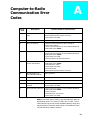
Appendix A - Computer-to-Radio Communication Error Codes . . . . . . . . . . . . . . . . . . . . . 329
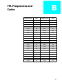
Appendix B - TPL Frequencies and Codes . . . . . . . . . . . . . . . . . . . . . . . . . . . . . . . . . . . . . . . 331
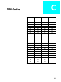
Appendix C - DPL Codes . . . . . . . . . . . . . . . . . . . . . . . . . . . . . . . . . . . . . . . . . . . . . . . . . . . . . 333
AppendixD - ASTRO Features . . . . . . . . . . . . . . . . . . . . . . . . . . . . . . . . . . . . . . . . . . . . . . . . . 335
AppendixE - Trunked Radio Personality Chart . . . . . . . . . . . . . . . . . . . . . . . . . . . . . . . . . . 343
AppendixF - Conventional Radio Personality Chart . . . . . . . . . . . . . . . . . . . . . . . . . . . . . . 345
Glossary. . . . . . . . . . . . . . . . . . . . . . . . . . . . . . . . . . . . . . . . . . . . . . . . . . . . . . . . . . . . . . . . . . . 347
Index . . . . . . . . . . . . . . . . . . . . . . . . . . . . . . . . . . . . . . . . . . . . . . . . . . . . . . . . . . . . . . . . . . . . . 361
iv
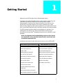
1
Getting Started
Welcome to the ASTRO Radio Service Software application!
This Radio Service Software (RSS) manual is your guide to customizing and
programming a variety of features into an ASTRO radio. Modern
microprocessor chip technology used to manufacture this radio and the
ASTRO RSS (a computer program, which when interfaced with a radio,
electronically programs a radio) make it possible for you to personalize a radio
with a unique set of features for each individual customer. No tools are needed.
The RSS computer program resides on the diskettes you received in the
package with this manual. The radio’s customization and servicing is
accomplished using an IBM® compatible computer with an 80386 or newer
processor.
Note: The alignment and troubleshooting sections of this manual
are intended for use by qualified communication technicians and
maintenance personnel only.
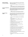
Listed below are some of major features and functions of the ASTRO RSS:
ASTRO RSS Programmable Features
ASTRO RSS Service Functions
Transmit (Tx) frequencies
Reference Oscillator alignment
Receive (Rx) frequencies
Transmit Deviation alignment
PL/DPL codes
Transmit Power alignment
Signalling System parameters
Replaced Power Amplifier calibration
Scan Lists and Scan options
Replaced Logic Board calibration
Radio Button and Soft Key features
Replaced RF board calibration
Phone Lists and options
Controller Board Initialization
Call Lists and options
Bit Error Rate Testing
Channel (customized) names
Test Pattern Transmission
Volume and Tone levels
Channel attributes (personalities)
Power Level
Special Software option parameters
Radio Software Upgrades via FLASHport
7
Prerequisites
To program radios using the RSS, we recommend a basic working knowledge
of the following:
• Microcomputers
• The radio’s available features (Refer to the appropriate Radio Operator’s
Manual.)
• Your customers’ needs
• MS-DOS operating system, version 5.0 or later
The ASTRO RSS requires a minimum of 510 kilobytes of free RAM to run. (The
DOS CHKDSK command can be used to determine the amount of free RAM
available on your computer.) DOS 5.0 is required. It is also strongly
recommended that this RSS be run on an IBM® compatible computer with an
80386 or newer processor with the following minimum configuration:
• 80386 CPU or higher
• DOS 5.0 or higher (with DOS running in high memory)
• 4 Megabytes of RAM or greater
The installation program will determine if your system has an adequate
amount of memory available (4M) and a 386 (or 486) CPU for extended
memory operation. If these are present, the RSS will be installed.
The powerful features and extensive flexibility of new radio families require
much more codeplug data validation than in the past. For complex
configurations, it is recommended that the RSS be executed from a RAM disk.
This will reduce execution time significantly. To configure your computer with
a RAM disk, you need to modify your CONFIG.SYS file with a statement. The
sample statement below is required to run the RSS in DOS 5.0:
DEVICE=C:\DOS\RAMDRIVE.SYS 4096 512 1024 /E
The following lines should also be added to the CONFIG.SYS file if necessary:
device = c:\dos\HIMEM.SYS
device = c: \dos\EMM386.EXE OFF
Files = 30
Note: The DOS MEM command can be used to determine the amount
of available memory in your computer (i.e. type c:\dos\mem. The
location of MEM.EXE may differ on your machine.) If the command reports
3000K or more of available extended memory, you can run the ASTRO
RSS.
8
Using This
Manual
The ASTRO RSS Manual is designed to teach basic radio feature programming
and to speed up access to technical reference information. It is intended for
both beginners and advanced users of the RSS. This manual contains
information on all of the following:
• How to connect the radio and other required hardware to your computer
• How to install the RSS
• How the RSS operates and how the screens are organized
• How to navigate through the menus and screens from the MAIN MENU
and use special keyboard commands
• What the purpose of each menu and screen is, along with detailed
descriptions of the functions and data fields relevant to each menu/screen
• How to program a radio using the GET/SAVE and CHANGE/VIEW screens
as well as how to service the radio using the SERVICE screens
• How to organize your file directories and specify directory paths for
codeplug files
• How to print out radio programming information
• How to clone (or program identical information into several) radios
To locate the information you need, use the Table of Contents and/or the
Index. For explanations of major terms used in this manual, refer to the
Glossary.
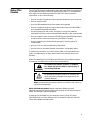
Watch for WARNINGS, CAUTIONS and NOTES which are used throughout
this manual, the definitions of which are provided below:
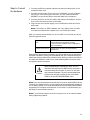
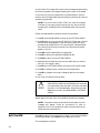
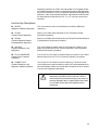
!
WARNING
!
Caution
An operational procedure, practice, or condition,
etc., which may result in death or serious injury if
not carefully observed.
An operational procedure, practice, or condition, etc.,
which may result in damage to the equipment if not
carefully observed.
Note: An operational procedure, practice, or condition, etc., which is
important to emphasize.
What italicized text means: Special notes about field and model
dependencies are italicized throughout this manual so that they are easy to
locate. An example is reproduced below:
A codeplug must be loaded into your computer’s memory (using GET/SAVE/
PROGRAM MENU functions) before you will be allowed to access the CHANGE/
VIEW MENU (F4) and related screens.
9
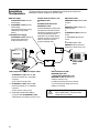
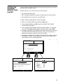
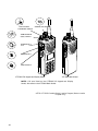
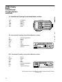
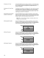
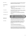
Assembling
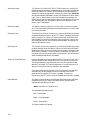
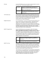
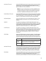
The Hardware
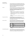
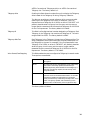
The figure below shows how to assemble the required (and optional)
equipment used to program an ASTRO radio.
Portable Products Test Set - P/N
RTX4005B or later
or
RTX4005A (with Rework Kit
RPX4665A) or later
RIB Power Supply
01-80357A57 or later (110 Vac)
Power Supply
or 01-80358A56 or later (220 Vac)
Power Supply
Using the power supply is more
reliable than using a weak
battery.
or Smart RIB Power Supply
01-80302E27 or later (120 Vac)
Power Supply (Required for
FLASHport operation only.)
Provides capability for testing many
transmitter and receiver functions.
Transmitter modulation and keying
can be simulated and receiver
parameters can be tested without
opening the radio. The Test Set is
used in conjunction with the
programming/test cable.
RIB-to-Radio Cable
RDN4046A or later (ASTRO SABER
Portable)
or
RKN4035A or later (ASTRO XTS
3000 Portable)
or
30-80369B73 or later (Mobile Low
Power)
or 0180300B10 (Mobile High
Power)
or
Smart RIB-to-Radio Cable
RKN4047A Cable (required for
FLASHport on Mobile radios only).
Computer
RIB
A
ASTRO SABER
Radio
B
Radio Interface Box (RIB)
RLN4008B RIB or later
or Smart Radio Interface Box (RIB)
RLN1015B or later RIB (Required for
FLASHport operation only.)
Radio Interface Box (RIB)-to-Computer Cable
30-80369B72 or later Cable for IBM
Personal Computer AT or compatible
computer
(9-pin end and a 15-pin end).
or 30-80369B71 or later Cable for IBM
Personal Computer XT or compatible
computer
(25-pin end and a 15-pin end)
or Smart Radio Interface Box (SRIB) to
Computer Cable 30-80390B48 or later
cable (Required for FLASHport operation only.)
10
For laptop computer and on-the-road use
only, omit the power supply and use a 9V
battery (not included).
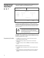
!
Caution
Use a fresh, 9V battery. LED remains lit
with a weak battery. This may cause
certain errors on screen.
Steps to Connect
the Hardware
1. Connect the RIB-to-computer cable to the communications port of the
computer (9-pin end).
2. Connect the other end (15-pin end) into the RIB Box. (If your computer
has a 25-pin connections port connector, you will need the cable 3080369B71 to connect the RIB-to-computer cable to the computer.)
3. Connect the 25-pin end of the RIB-to-radio cable to the RIB box, and the
9-pin end to the side connector of the radio.
4. Plug one end of the power supply into the RIB and the other end into a
wall outlet.
Note: Connections of SRIB hardware will vary slightly from the RIBconnection procedure with respect to pin connectors and cables.
After you connect the hardware, turn on the radio. You will hear one of the
following types of tones:
High-pitched, short
tone
Hardware is connected correctly and the radio’s
internal firmware is operating correctly.
This tone may be disabled in the codeplug and
may not be heard.
Continuous low tone
Critical failure or radio’s internal software
malfunction.
Even without the necessary hardware, you will be able to start or explore the
RSS (after installation) using just the diskettes and your computer simply by
loading an existing radio archive stored on disk. What you cannot do without
the required hardware is read from or save codeplug data to an actual radio
and perform service functions.
!
Caution
When programming or calibrating a radio, DO NOT
disconnect the radio from the RIB when the computer is
communicating with the radio. If you do so, the radio
may become inoperable. The only recommended time
to disconnect the radio is while you are at the MAIN
MENU or at the GET/SAVE/PROGRAM menu.
Note: If you are using a laptop computer and you plan to use the RSS while the
computer is in battery mode, you may need to set the serial/parallel adapter to
run on battery power. This can be accomplished using the application diskette
supplied by the computer manufacturer. If this action is not performed, you
are likely to receive serial bus errors.
Note: If your RIB has a switch and LED, be sure to turn on the switch before
each programming session.
11
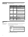
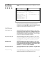
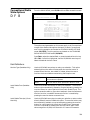
What’s On The
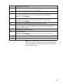
RSS Diskettes
Below are the names and descriptions of files located on the diskettes you
received with this manual.
File Name
File Type
Description
Disk #1
INSTALL.EXE
Installation file
Installation program.
RSS.001
Compressed file
Compressed version of the file that the
installation program uncompresses
when it installs the RSS on your hard
disk.
README.TXT
Text file
RSS release information that could not
be included in the manual. Open this
document using your DOS/other editor
preferably before you install the new
RSS.
Compressed file
Compressed version of the file that the
installation program uncompresses
when it installs the RSS on your hard
disk.
Disk #2
RSS.002
The following files can be found on both diskettes:
INSTALL.DAT
Installation file
Installation data.
DISK.ID
Installation file
Identification information used by the
installation program.
Installing The
RSS
Create a Back-up Copy
of RSS Diskette(s)
We recommend that you make a back-up copy of the RSS. To make a back-up
copy, follow the steps below for each diskette.
1. Insert the RSS diskette you received with this manual into drive A.
2. Type DISKCOPY A: A:
!
Caution
Accidentally reversing the insertion order of the diskettes
will erase the contents of the RSS diskette. DOS will tell
you when to insert the source diskette (the original RSS
diskette) and when to insert the target diskette (a newly
formatted one). When the disk copy command has been
executed, use the target diskette as the new working
copy.
3. Use the backup copy and keep the original RSS diskettes in a safe place
away from magnets, moisture and heat.
12
What To Do with Previous
Versions of RSS Diskettes
We recommend that you discard previous versions of the RSS so that you
always have the most current version available and do not mistakenly
program a radio with outdated data. In addition, the latest RSS version has
updated codeplug structures which will be unreadable with old versions of the
RSS.
Installing the RSS on
your Hard Disk
Install the latest RSS version as soon as you receive it. This ensures that you
have the latest version of the RSS installed at all times. This action also stores
important files in a consistent place for cross-referencing and future use. The
software installation will take approximately three minutes.
The INSTALL program will:
• Create the MRSS directory and the ASTRO, ARCHIVEM and/or ARCHIVEP,
OFP, SRIB, SYSKEY, and UPGRADE sub-directories if they do not already
exist. (For mobiles, the archive directory will be named ARCHIVEM, and
for portables, it will be named ARCHIVEP.)
• Write over the old version’s program files with the same name, if the
names are the same.
Note: The installation program will NOT write over your archive files.
You may install the RSS on several personal computers and laptop computers
at a single site depending on the terms of your license. If you have additional
sites (i.e. a second shop, etc.) you should purchase additional subscriptions.
Note: The RSS is NOT a Windows or OS/2 program. Windows or
OS/2 cannot be loaded when you install or run the RSS. If you do,
the RSS will not operate correctly.
RSS Hard Disk Installation
1. Insert the RSS diskette marked Disk 1 in drive A.
2. Type A: (press Return).
3. At the A: prompt, type INSTALL.
Follow directions and answer questions on the display as and when they
appear. You will be instructed to switch diskettes in the diskette drive (ex.
“INSERT DISK CONTAINING FILE...”).
When installation is complete, you may notice a number of new files on your
hard disk depending on the particular RSS (Portable, Mobile or Both) you
installed. These files are listed on the following page. With the exception of
README.TXT files, do not delete or move these files from their locations.
13
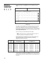
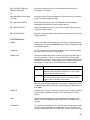
File Name
RSS Start-Up Procedure
Location
Description
RUNTIME.EXE
\mrss\astro
RSS application executable
program.
SMARTRIB.ENC
\mrss\astro\srib
Used by the RSS to configure your
SmartRIB.
ASTROM.ODB
\mrss\astro
Used by the RSS to configure
ASTRO Mobile radios.
ASTROP.ODB
\mrss\astro
Used by the RSS to configure
ASTRO Portable radios.
ASTROM.BAT
\
A batch file that launches the
ASTRO Mobile RSS application.
ASTROM.BAT
\mrss\astro
A batch file that launches the
ASTRO Mobile RSS application.
ASTROP.BAT
\
A batch file that launches the
ASTRO Portable RSS application.
ASTROP.BAT
\mrss\astro
A batch file that launches the
ASTRO Portable RSS application.
ASTMHOPT.MDF
\mrss\astro
Used by the RSS to configure
ASTRO Mobile radios.
ASTPHOPT.MDF
\mrss\astro
Used by the RSS to configure
ASTRO Portable radios.
ASTROMBC.ENC
\mrss\astro\upgrade
Used by the RSS to configure
ASTRO Mobile radios.
ASTROPBC.ENC
\mrss\astro\upgrade
Used by the RSS to configure
ASTRO Portable radios.
Once installation is complete, follow the start-up procedure below:
1. Type C: and press Return to log on to the hard drive.
2. At the C:\ prompt type ASTROP or ASTROM (depending on which RSS you
installed or which you would like to run).
This command starts up the RSS. If the software does not start up correctly, you
may hear a tone or see an error message or error code on the display.
Note: If you did not read the accompanying README.TXT file prior
to performing the installation, you may want to do so now. Special
release information contained in this file may be of great value to
you.
14
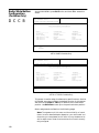
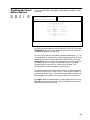
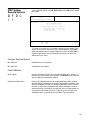
The Banner
Screen
When the program has been successfully loaded in your computer, you will see
a BANNER screen like the one below with the Motorola logo and RSS copyright
information.
MOTOROLA
RADIO SERVICE SOFTWARE
for the
ASTRO Mobile
Radios
<Version>
<Date>
25
Press Any Key To Continue
Copyright Motorola Inc. 1992-1996, All rights reserved.
Banner Screen for Mobile Version of RSS
MOTOROLA
RADIO SERVICE SOFTWARE
for the
ASTRO Portable
Radios
<Version>
<Date>
25
Press Any Key To Continue
Copyright Motorola Inc. 1992-1996. All rights reserved.
Banner Screen for Portable Version of RSS
Note: The Version and Date are not shown on the BANNER screen above.
However, your RSS will show the actual version and date on the
BANNER screen.
Press any key to access the MAIN MENU.
15
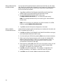
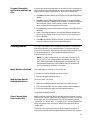
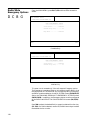
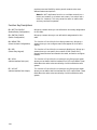
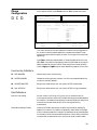
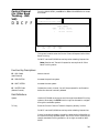
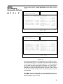
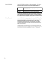
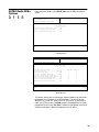
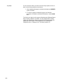
Anatomy of a
Menu
The RSS consists of several multi-level menus that will take you to screens
where you can change the choice or value of a field. The only difference
between a menu and a screen is nature of the information that appears in the
working area (marked by the letter C in the figure below). A menu or screen has
four areas, labelled below as A, B, C and D.
MOTOROLA Radio Service Software
ASTRO
Model:
Select Function F1 - F10.
A
MAIN
B
A
MAIN MENU
--------F1
F2
F3
F4
F5
F6
F7
F8
F9
F10
F1
HELP
A
RSS Location ID
Area
F2
SERVICE
MENU
-
HELP
SERVICE: Alignment (Requires RIB)
GET/SAVE/PROGRAM/CLONE Codeplug Data from/to Disk/Radio
CHANGE/VIEW Radio Codeplug Data
PRINT Radio Codeplug Data
FILE Maintenance
C
FLASHport Upgrade
SETUP Computer Configuration
Exit Radio Service Software, Return to DOS
F3
GET
SAVE
F4
CHANGE
VIEW
F5
PRINT
DATA
F6
FILE
MAINT
F7
D
F8
FLASHport
UPGRADE
F9
SETUP
MENU
F10
EXIT
TO DOS
In this area you will find the words “MOTOROLA Radio Service Software”,
“ASTRO MOBILE” or “ASTRO PORTABLE”, and a menu or screen path name
for the current menu or screen. Each menu and screen name will be separated
by a colon (:). If a radio codeplug has been read, its model number will also be
displayed in this area.
B Instruction Area
As the name indicates, this area directs you to perform specific actions such as
“Select Function, F1-F10”, “Use UP/DOWN arrows to scroll value,” and so on.
The first two lines contain suggestions for the appropriate action, and the last
two lines are status lines.
C Working Area
This area of a menu (not a screen) displays a list of functions (menu choices)
you can execute from the current menu. Each menu item is preceded by an Fkey (function key). Pressing an F-key from among the available choices will
bring up another menu or screen as the case may be.
D F-Key (Function-
This area displays the F-keys and function names for the current menu or
screen. Each menu item is preceded by an F-number key (function key).
Pressing an F-number key advances you to another menu, screen, or performs
the indicated operation.
Key) ID Area
Note: All functions (supported and unsupported) will be displayed in
the menu’s working area. The unsupported functions (based on the
radio’s model or options) will; however, NOT be displayed in the F-key
area.
16
Navigating
Through The
RSS Menus
Every action of the RSS is controlled by you through the use of formatted
displays and function keys.
Under each menu or screen title, you will find a sequence of F-keys (or
Function keys) such as DCE . This sequence represents the path from the
MAIN MENU to that specific menu or screen. To access the desired menu or
screen, simply press these keys one by one from the MAIN MENU.
The F-keys and other special keys that you can use to communicate with the
RSS are listed below along with their various functions.
F1
Used to display on-line help information on every RSS screen and menu. Online help provides information on how to use the currently displayed menu,
screen, line or field. You may also find system setup information in a HELP
screen. In many cases, the help information provided is for the specific line of
the screen that is currently highlighted.
F2 through F9
The F2 through F9 keys perform special functions and actions which can vary
from menu to menu and from screen to screen. For instance, on some screens,
F5 will print out the current screen to your printer, F8 will save the data and
options currently displayed, and so on.
F10
Used to exit to previous menu or screen. The F10 key performs this function
on every menu and screen. At the MAIN MENU, the F10 key is used to exit the
RSS.
Esc
Used to exit to the MAIN MENU. The Esc key performs this function on every
menu and screen.
Tab
Accepts data currently in the field and then moves the prompt forward one
field. If the entry is not accepted, an error beep will sound. The value you
entered is probably not a valid value. Functions like the Enter or Return key.
Left/Right Arrows
Used to move in the direction of the arrow. The Num Lock key must be off.
UP/DOWN Arrows
Used to scroll through selections, or to increase/decrease the value in the
highlighted field. Num Lock key must be off.
Del
Used to erase the current character in a field.
PgUp
Used to display the previous page of information on the screen.
PgDn
Used to display the next page of information on the screen. The Num Lock
key must be off.
17
Anatomy of a
Screen
The only difference between a menu and a screen lies in the contents of the
working area.
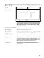
MOTOROLA Radio Service Software
ASTRO
Model:
Enter or Scroll to Select Frequency.
MAIN:CHANGE/VIEW:CONV:PERS
Personality........1
CONVENTIONAL PERSONALITY
-----------------------Signalling.....................MDC
Receive Only..............Disabled
MDC System #...................1
Direct / Talkaround........Enabled
PTT ID..................Disabled
Time Out Timer..........360
Scan List........................1
Revert..........Selected Channel
Hot Keypad................Disabled
Rx Voice/Signal Type.....Non-ASTRO
Phone Operation..........Unlimited
Tx Voice/Signal Type.....Non-ASTRO
Frequency (MHz)
Squelch Type
Code
DPL Invert
F1
HELP
F2
ADD
PERS
F3
PREV
PERS
Receive
851.01250
PL
67.0 Hz XZ
F4
NEXT
PERS
F5
DELETE
PERS
Transmit
806.05000
PL
67.0 Hz XZ
Direct
851.01250
PL
67.0 Hz XZ
F6
F7
F8
F9
SECURE
MDC
PHONE
MORE
OPTIONS OPTIONS OPTIONS OPTIONS
F10
EXIT
The working area of a screen contains a list of programmable features called
“fields” that can be selected or changed using the arrow, tab or return keys
described earlier. On some screens, there are features that can be selected for
each individual channel or mode; these features are selected on a mode-bymode basis.
A
18
On other screens, there are features that can be selected for all modes of the
radio (referred to as “radio-wide” features). And still other screens list those
features that perform specific RSS functions, such as servicing the radio or
printing the personality data.
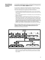
Complete
Menu Mapping
at a Glance
The menu map below is a guide through the entire RSS.
MAIN MENU
B
A
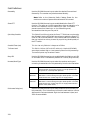
HELP
SERVICE
C
GET/ SAVE/
PROGRAM
D
CHANGE/VIEW
F
E
PRINT MENU
FILE
MAINTENANCE
G
H
FLASHport
UPGRADE
I
SETUP
J
EXIT
TO
DOS
Refer to the
following page
B Transmit Alignment Menu
B Reference Oscillator
C Transmit Power
(Compensation)
D Transmit Deviation Balance
E Transmit Deviation Limit
Transmit VCO Crossover
F Frequency
(Portables Only)
C
(or)
Transmit Current Limit
(Mobiles Only)
Receiver Alignment Menu
(Portables Only)
Front End Bandpass Filter
(Portables Only)
Rx VCO Crossover
Frequency (Portables Only)
Controller Board Initialization
B
C
I
Refer to the
FLASHport
User’s Guide
for sub-menus
B Create Directory Path
E Delete Archive File
C PC Configuration
G Screen Color Configuration
Wide Buttons, Switches, Display,
C Radio
Scan, Phone
Systems,
D Trunking
Personalities, Call Lists, Options
Read Data from Radio
B Codeplug
(Requires RIB)
C Get Codeplug Data from
Archive Disk File
E Clone Radio
Save Codeplug Data
G to
Archive Disk File
Systems,
F Conventional
Personalities, MDC, Options
H Zone/Channel Assignment
I Radio Codeplug Data Summary
(Refer to Section 6 for sub-menus)
Program Data Into Radio
H Codeplug
(Requires RIB)
Radio
Programming
History
I
19
CHANGE/ VIEW
C Radio Wide Buttons, Switches, Display, Scan, Phone
B Radio Wide Options
F Radio Wide SECURE Options
C Hardware Encryption Multi-key Options
D Software Encryption Multi-key Options
E Software Key Entry
F More Multi-key Options
G OTAR Options
G Radio Wide Emergency Options
I More Radio Wide Options
B Siren and PA Options
C VRS Options
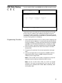
G VRS-EP Mode Steering
C Buttons, Switches, Menu Items
B Button/Rotary Configuration
B Conventional/Trunking HHCH Buttons
(Portables only)
D
E
F
G
I
C Switch Configuration
D Menu Item Configuration
E DEK Button Configuration (Mobiles only)
F VIP In (Mobiles only)
G VIP Out (Mobiles only)
Phone Lists and Options
H DTMF Access/De-Access Codes
I Dialing Options
Systems, Personalities,
D Trunking
Call Lists, Options
B Trunking Radio Wide Options
B SmartZone Environment
C VOC Options
Trunking Systems: System ID,
C Control
Channels, etc.
F Control Channel
G Multi-key Options
H ASTRO Options
I Trunking System Options
E One-Touch Button Options
F Trunking Status Alias
G Trunking Message Alias
H Trunking Site Alias
Personality: Talk Groups,
D Trunking
Emergency Options, etc.
F WAC AMSS Failsoft
G Trunking Talkgroup/Subfleet
H Emergency Data Configuration
I Trunking Personality Options
F SmartZone Preferred Sites
E Trunking Call List Data
Scan Lists and Options
H Scan Options
Display Options
G PTT-ID
Alarm Options (Mobiles only)
More Radio Wide Options (Mobiles only)
B Siren and PA Options (Mobiles only)
C VRS Options (Mobiles only)
G VRS-EP Options (Mobiles only)
Some of the menu items
shown here MAY NOT be
available if some features
were not purchased for the
radio.
Continued on the following
page
20
CHANGE/VIEW MENU (Continued)
Some of the menu items
shown here MAY NOT be
available if some features
were not purchased for the
radio.
CHANGE/ VIEW
F Conventional Systems, Personalities, MDC, Options
B Conventional Radio Wide Configuration
C Conventional Personalities, Options
F Secure Options
G MDC Options
H Phone Options
I More Options
F ASTRO Options
F ASTRO Conventional Talkgroup Options
G OTACR, OTACS
G RAC Options
D MDC Systems, Options, Call List
C MDC Systems
I More Options
I MDC Systems Remote Options
D MDC Call List Data
E MDC Repeater ID List
E ASTRO Systems, Options, Call List
B ASTRO Radio Wide Configuration
C ASTRO Systems
G Soft ID
I More Options
I ASTRO Systems Remote Options
D ASTRO Call List Data
E ASTRO Data Peripheral (Mobiles only)
FASTRO Conventional Talkgroups
F MODAT
G Auxiliary Systems
B Singletone Systems
C Singletone List
H Conventional Message Alias List
I Conventional Status Alias List
H Zone/Channel Assignment
21
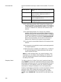
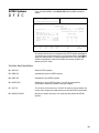
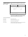
Changing A
Field Value
Some screens contain fields that require, or take values from, other screens and
features and thus are dependent upon each other. For example, the System ID
number specified in the CHANGE/VIEW:TRUNKING:PERS screen are assigned
in the CHANGE/VIEW:TRUNKING:SYSTEM screen.
Press Tab or Enter to
move to field, and then
type E for Enabled or D for
Disabled.
MOTOROLA Radio Service Software
ASTRO
Model:
Enter or Scroll to Select Frequency.
MAIN:CHANGE/VIEW:CONV:PERS
Personality........1
CONVENTIONAL PERSONALITY
-----------------------Signalling.....................MDC
Receive Only..............Disabled
MDC System #...................1
Direct / Talkaround........Enabled
PTT ID..................Disabled
Time Out Timer..........360
Scan List........................1
Revert..........Selected Channel
Hot Keypad................Disabled
Rx Voice/Signal Type.....Non-ASTRO
Phone Operation..........Unlimited
Tx Voice/Signal Type.....Non-ASTRO
Frequency (MHz)
Squelch Type
Code
DPL Invert
F1
HELP
F2
ADD
PERS
F3
PREV
PERS
Receive
851.01250
PL
67.0 Hz XZ
F4
NEXT
PERS
F5
DELETE
PERS
Transmit
806.05000
PL
67.0 Hz XZ
Direct
851.01250
PL
67.0 Hz XZ
F6
F7
F8
F9
SECURE
MDC
PHONE
MORE
OPTIONS OPTIONS OPTIONS OPTIONS
F10
EXIT
Press or
to
change value, or type
new value.
Screen fields come in three basic types:
Information fields
Non-editable fields which cannot be altered or changed.
Scrollable fields
Contain a range of values, or several options, from which you can select the
desired value/option. To edit or change a choice, press the arrow key(s).
Direct-entry fields
The desired value must be typed in using the keyboard. To edit or change a
choice, type in an acceptable value.
Changing a field’s value is typically done either by scrolling through a list of
options (in scrollable fields) or by typing in a correct value (in direct-entry
fields). Scrolling is accomplished using the arrow keys.
22
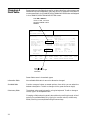
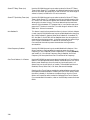
Configuring
Computer
Defaults from
the RSS
Setting computer defaults eliminates the need to specify them every time you
enter the RSS or program a radio.
Read this section if you wish to do any of the following:
• Set a default file path name
• Set or change the default port used to interface with the radio and RIB
• Set the default colors you see on your RSS screen
To begin configuring RSS defaults, follow these steps:
1. Return to the MAIN MENU by pressing the Esc button.
2. From the MAIN MENU, press F9 to get to the SERVICE SOFTWARE
CONFIGURATION MENU.
3. From the SERVICE SOFTWARE CONFIGURATION MENU, you can read
the on-line help (F1), set some default computer values, or exit (F10).
4. Press F3 on the SERVICE SOFTWARE CONFIGURATION MENU to bring up
the CONFIGURE PATHS AND PORT screen. Here, you can specify the
default drive and path names for future archive files.
5. Press F7 on the SERVICE SOFTWARE CONFIGURATION MENU to display
the SCREEN COLORS. You can specify the colors for your screen’s text,
lines, background, and highlighted fields.
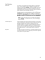
ISS.
LETTERING SIZE:
REQUIRES:
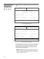
MOTOROLA Radio Service Software
ASTRO
Model: H04SDH9PW7AN
REVISION
O
A
Revised Scree
MAIN:CONFIGURATION
SERVICE SOFTWARE CONFIGURATION
F1
F2
F3
F4
F5
F6
F7
F8
F9
F10
-
-
-
-
-
-
-
HELP
PC CONFIGURATION, Drives, Paths, Ports, etc.
SCREEN Color Configuration
Exit, Return To Main Menu
F1
HELP
F2
F3
F4
CONFIGURE PC
F3
MOTOROLA Radio Service Software
ASTRO
Model: H04SDH9PW7AN
F5
F6
F7
SCREEN
COLORS
F8
F9
F10
EXIT
F7
Enter Path Name.
MOTOROLA Radio Service Software
ASTRO
Model: H04SDH9PW7AN
MAIN:CONFIGURATION:SCREEN COLORS
MAIN:CONFIGURATION:PC
CONFIGURE PATHS AND PORT
SCREEN COLORS
Archive Path:....C/MRSS\ASTRO\ARCHIVEP
FLASH Software Path:...C/MRSS\ASTRO\UPGRADE
BootstrapCode Path & File Name:...C/MRSS\ASTRO\UPGRADE\ASTROPBC.ENC
SRIB Software Path and File Name:...C/MRSS\ASTRO\SRIB\SMARTRIB.ENC
System Key:...........C/MRSS\ASTRO\SYSKEY
TCMS Path.....
RIB...................................COM 1
F1
HELP
F2
F3
Use Up/ Down arrows to Select.
F4
F5
F6
COM
TEST
F7
F8
SAVE
F9
F10
EXIT
MONITOR TYPE . . . . . . . . . . . . . . Color
TEXT. . . . . . . . . . . . . . .. . . . . . Yellow
STATUS TEXT . . . . . . . . . . . . . . . Yellow
MESSAGE TEXT. . . . . . . . . . . . . White
HIGHLIGHT . . . . . . . . . . . . . . . . Green
BACKGROUND. . . . . . . . . . . . . . Blue
FRAME. . . . . . . . . . . . . . . . . . . . . . Red
SELECTED TEXT. . . . . . . . . . . . . Yellow
POPUP BACKGROUND. .. . . . . . Brown
F1
HELP
F2
F3
F4
F5
F6
F7
F8
SAVE
F9
F10
EXIT
23
Setting Default Archive
and Back-up Paths
You can set the drive name and path names for archive files you will create
later. Specifying a default path name early on will save much typing time later
every time you want to save an archive file. Here’s how to set the default
archive and back-up file paths:
1. Press F3 at the SERVICE SOFTWARE COMPUTER CONFIGURATION
MENU to get to the CONFIGURE PATHS AND PORT screen.
2. At the CONFIGURE PATHS AND PORT screen, type
C:\MRSS\ASTROP\ARCHIVEP (i.e., the archive file path name).
Note: This example assumes that you are storing your archive files on
the hard disk.
Note: The Archive Path in this example is for ASTRO Portables. For ASTRO
Mobiles, type C:\MRSS\ASTRO\ARCHIVEM.
3. Type F8 to save the field options displayed on the screen.
Setting a Default
Communications Port
Use the following steps to specify the serial port to interface with the radio and
RIB. The default port is COM 1.
1. Press F3 at the SERVICE SOFTWARE CONFIGURATION MENU to bring up
the CONFIGURE PATHS AND PORT screen.
2. Go to the serial port RIB field by pressing Tab as many times as necessary.
3. Select a port using the arrow keys to scroll through the available field
options. Options are COM 1, COM 2. On some computers, COM 3, or
COM 4 may also be available. Choose the port to which you have
connected the computer-to-RIB cable.
4. Test the port by pressing F6, COM TEST. If the connection is okay, you will
hear a beep, and the words “Communications With The Radio Was
Successful” will appear in the instruction area.
5. Press F8 to save this configuration. The message “Configuration File
Written Successfully” will appear in instruction area of the screen.
6. Press F10 to exit this screen or Esc to access the MAIN MENU.
24
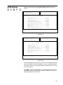
Retrieving RSS
Version &
Parts
Information
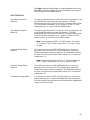
The RSS has a help screen that contains information on the RSS and a list of
relevant RSS programming accessory part numbers.
To display this information, simply press F1 and then F9 from any menu or
(non-help) screen. If you are already in a Help screen, press F9. A sample screen
is provided below.
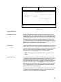
MOTOROLA Radio Service Software
ASTRO
Model:
Page 1 of 3
...CONFIG:FEATURES:SWITCHES:HELP
MOTOROLA Radio Service Software Information
------------------------------------------8961
RSS Version D04.03.00
06/07/96
Motorola Part Number
-------------------RLN-4008B
60-82728J01 or
01-80357A57 or
01-80358A56
30-80369B71 or
F1
MORE
HELP
Exiting the RSS
F2
KEYBOARD
HELP
F3
Equipment
--------Radio Interface Box (RIB)
Power supply (9V) for RIB
Power supply (110V) for RIB
Power supply (220V) for RIB
RIB to Computer Cable (25-pin connector for
models such as IBM PC, XT, Personal System/2,
Compatible)
F4
F5
PRINT
F6
F7
F8
F9
RSS
INFO
F10
EXIT
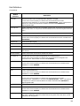
Before you exit the RSS, always ask yourself these questions:
1. Did you apply the changes to the radio (save to the radio)?
2. Did you apply the changes to a computer file (save archive file)?
Note: If you have not saved your changes to an archive file or to a
radio codeplug at the time that you exit the RSS, all the changes will
be lost.
Press the Esc key to return to the MAIN MENU, and then press F10 followed
by F2 to exit to the DOS prompt.
25
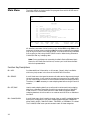
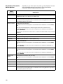
Main Menu
The MAIN MENU is the top level of the program from which all RSS menus
and screens can be accessed.
MOTOROLA Radio Service Software
ASTRO
Model:
Select Function F1 - F10.
MAIN
MAIN MENU
--------F1
F2
F3
F4
F5
F6
F7
F8
F9
F10
F1
HELP
F2
SERVICE
MENU
-
HELP
SERVICE: Alignment (Requires RIB)
GET/SAVE/PROGRAM/CLONE Codeplug Data from/to Disk/Radio
CHANGE/VIEW Radio Codeplug Data
PRINT Radio Codeplug Data
FILE Maintenance
FLASHport Upgrade
SETUP Computer Configuration
Exit Radio Service Software, Return to DOS
F3
GET
SAVE
F4
CHANGE
VIEW
F5
PRINT
DATA
F6
FILE
MAINT
F7
F8
FLASHport
UPGRADE
F9
SETUP
MENU
F10
EXIT
TO DOS
All selections are made via the function keys, labeled F1 through F10 on the
keyboard. All other menus contain an Esc key, and by pressing it the operator
may at any time return to the MAIN MENU. The user must initially load data
from a radio (or disk) using the GET/SAVE function before being allowed to
CHANGE/VIEW any codeplug data.
Note: For any problems not covered by the Radio Service Software User’s
Manual or the Radio Service Manual, contact your local Motorola field
technical representative.
Function Key Descriptions
F1 - HELP
Provides additional information on this screen. Generic help is available
within any help screen in the form of the MORE HELP function.
F2 - SERVICE
A multi-level menu that permits access to all radio service alignments through
the service screens. A radio must be connected to the computer via the RIB before
you can access the service screens. All service screens access the codeplug directly.
Therefore, it is NOT necessary to read codeplug data before using the service
screens.
F3 - GET/SAVE
Used to read codeplug data from a radio and/or retrieve-archived codeplug
data from a diskette or hard disk for editing purposes using the CHANGE/
VIEW function. The GET/SAVE function is also used to program edited
codeplug data back into the radio or to create an archive file on a diskette or
hard disk.
F4 - CHANGE/VIEW
A multi-level menu that is used to change, view, or modify codeplug features
and option configurations. All radio codeplug parameters are classified as
either RADIO WIDE, CONVENTIONAL, TRUNKED, or PERSONALITY-related.
The CHANGE/VIEW menu permits access to each of these categories.
26
Unlike the SERVICE function, a codeplug must be loaded into the computer’s
memory using GET/SAVE functions before CHANGE/VIEW functions can be
accessed. An archive file can be accessed without a radio being connected.
F5 - PRINT MENU
Prints selected codeplug data.
F6 - FILE MAINT
Allow access to archives so that you can retrieve codeplug data or find/create
paths to enter or store archive files.
F8 - FLASHport
UPGRADE
Allows you to upgrade your radio’s internal software and/or add new options
to your radio.
F9 - SETUP MENU
Used to configure the Radio Service Software according to specific user
requirements. Default disk drives, communication ports, and even screen
colors may be customized to the customer’s specific needs.
F10 - EXIT TO DOS
Used to quit the program and return to DOS. Make sure that all desired
codeplug changes have been programmed back to the radio and that an
archive copy has been made. If this is not done, all changes will be lost as
returning to DOS erases this data from the computer’s memory.
How to Read the
Codeplug
1. Start up the RSS. If you are not already at the MAIN MENU, press any key
at the BANNER screen to access the MAIN MENU.
2. From the MAIN MENU press F3; the GET/SAVE/PROGRAM MENU will be
displayed.
You can read the codeplug from the radio or from the archive disk. After
reading, the codeplug will be checked for valid serial number, model number,
checksums, etc.
Reading Codeplug Data
from the Radio
Connect the radio to the computer according to instructions provided on
page 10.Turn the radio on and press F2. A series of status messages will appear
in the upper right corner of the screen. If a communication error occurs, a popup window will be displayed.
Note: Refer to Appendix A for an explanation of computer-to-radio
communication error codes.
If no errors occur, the center of the screen will display the progress of the
codeplug read activity. After the codeplug is read, the GET/SAVE/PROGRAM
MENU will be displayed.
Reading Disk Codeplug
Files
Press F3 at the GET/SAVE/PROGRAM MENU. The ARCHIVE FILE screen will be
displayed. An archive path and the list of files in that path will be displayed.
By default, the path will be the corresponding archive path specified on the
CONFIGURE PATHS AND PORT screen. If you want to retrieve a file from
another path, press F2, type in the path name, and then press Enter. The
names of the files in the new path will be displayed.
To retrieve a selected file, press Tab or Enter to move to the desired file and
then press F8. The selected file will be retrieved, validated, and placed in
computer memory. The progress of the read process will be displayed on the
screen. To delete a file, select it and press F5.
27
Service
Software
Configuration
The SERVICE SOFTWARE CONFIGURATION screen can be accessed by
pressing F9 at the MAIN MENU.
MOTOROLA Radio Service Software
ASTRO
Model:
I
Select Function F1 - F10.
MAIN:CONFIGURATION
SERVICE SOFTWARE CONFIGURATION
-----------------------------F1
F2
F3
F4
F5
F6
F7
F8
F9
F10
F1
HELP
F2
-
HELP
PC CONFIGURATION: Drives, Paths, Ports, etc.
SCREEN Color Configuration
Exit, Return to Main Menu
F3
CONFIGURE
PC
F4
F5
F6
F7
SCREEN
COLORS
F8
F9
F10
EXIT
From this screen, you can set up the paths for archive files. You will also be able
to set up the serial port (COM 1 or COM 2) that will be used to communicate
with the radio.
Function Key Descriptions
F1 - HELP
Provides useful information about the currently displayed menu, screen, or
field.
F3 - CONFIGURE PC
Used to set default disk drive paths for archive files and back-up files. It is also
used to select the asynchronous communications port (COM 1 or COM 2) that
the RIB will be connected to. The RSS will automatically determine what clock
speed the computer is operating at.
Note: Refer to the owner’s manual that came with your computer for a
complete description of path names and asynchronous communication
ports.
F7 - SCREEN COLORS
Used to enable the monochrome display option. However, if the computer is
capable of color display, viewing quality is greatly enhanced. The standard
default configuration for the RSS is for a color display monitor.
F10 - EXIT
Moves the display backward in the RSS tree, one screen or menu at time.
28
Configure
Paths and Port
From the MAIN MENU, press F9 and then F3 to access this screen.
MOTOROLA Radio Service Software
ASTRO
Model:
IC
Enter Path.
MAIN:CONFIGURATION:PC
CONFIGURE PATHS AND PORT
-----------------------Archive Path:....C:\MRSS\ASTRO\ARCHIVEM
FLASH Software Path:..C:\MRSS\ASTRO\UPGRADE
BootstrapCode Path & FileName:..C:\MRSS\ASTRO\UPGRADE\ASTROMBC.ENC
SRIB Software Path & FileName:..C:\MRSS\ASTRO\SRIB\SMARTRIB.ENC
System Key:......
RIB...........COM 1
F1
HELP
F2
F3
F4
F5
F6
COM
TEST
F7
F8
SAVE
F9
F10
EXIT
This screen is used to set default disk drive paths for archive files, back-up files,
and TCMS authorization files. It is also used to select the asynchronous
communications port (COM 1 or COM 2) that the RIB/SRIB (radio interface
box) will be connected to.
Note: The Archive Path and the Bootstrap Code Path and FileName entries in
this example are for ASTRO Mobiles only. For ASTRO Portables, the Archive
Path will be C:\MRSS\ASTRO\ ARCHIVEP and the Bootstrap Code Path
and FileName will be C:\MRSS\ASTRO\UPGRADE\ASTROPBC.ENC.
Note: Refer to the owner’s manual that came with your computer for a
complete description of directory path names and asynchronous
communications ports.
Function Key Descriptions
F6 - COM TEST
(Communications Test)
Used to verify if your computer is set up correctly and is able to read and
program a radio codeplug properly. After your computer and RIB are
connected according to instructions in the Radio Service Software manual and
you have selected the appropriate communication port, turn on your radio
and execute the COM TEST function by pressing F6.
COM TEST will verify if your system is functioning properly by sending
commands to the radio and checking for the proper response. No codeplug
changes will result from these commands. An OK response will be displayed
in the Status Window if the system checks OK. Otherwise, error messages will
be displayed and you should consult Appendix A to diagnose the problem.
F8 - SAVE
Used to save configuration information to a file on your program disk. The
configuration that you saved last will be used every time you run the RSS. The
configuration may be changed and saved at any time.
29
Field Definitions
Archive Path
Enter the default directory path where archive files are to be located. The GET/
SAVE:SAVE FILE function will default to this path. Refer to the owner’s manual
that came with your computer for a complete description of directories and
path names.
FLASH Software Path
Enter the default directory path where FLASHport Upgrade files are located.
The default path established by the RSS installation program is
C:\MRSS\ASTRO\UPGRADE.
Note: In order to ensure a successful FLASHport upgrade, it is
STRONGLY recommended that none of the files installed by the RSS
installation program be moved, overwritten by the user, or renamed.
Prior to performing a FLASHport upgrade, the RSS displays the list of files that
exist in the path entered here. You will then be asked to select the desired
FLASHport Upgrade Software Kit and press F8 to start the upgrade process.
Bootstrap Code Path
and FileName
Enter the default path and the default name for the bootstrap software used
during FLASHport operation. The default path established by the RSS
installation program is C:\MRSS\ASTRO\UPGRADE. The default file names
are ASTROMBC.ENC and ASTROPBC.ENC for the Mobile and Portable RSS
respectively.
SRIB Software Path
and FileName
Enter the default directory path and the default name for the SRIB software
file. The default path established by the RSS installation program is
C:\MRSS\ASTRO\SRIB, and the default file name is SMARTRIB.ENC.
Note: In order to ensure a successful FLASHport upgrade, it is strongly
recommended that none of the files installed by the RSS installation
program be moved, overwritten, or renamed.
System Key
Enter the default DOS directory path where Trunking System Keys are to be
located. The LOAD SYS KEY function will default to this path.
RIB
Use the UP/DOWN arrow keys to select the asynchronous communications
port (COM 1 or COM 2) that the RIB (Radio Interface Box) is connected to.
If you are not sure how your computer is configured or if you have two
asynchronous communications ports, first select COM 1 and use the COM
TEST (F6) function to communicate with a radio. If the test fails, select COM
2 and repeat COM TEST. Make sure that all cables and power supplies are
connected according to instructions provided in your RSS Manual. For a list of
computer-to-radio communication error codes, refer to Appendix A.
30
It is important to spend some time early on deciding which types or groups of
files should be located together in the same file directory. File directories can
be created using the DOS MD or MKDIR command.
Special Notes on
Organizing Your
Hard Disk
You may want to organize your directories first by customer area, then by
customer name, and finally by radio model type, or perhaps in the reverse
order. When deciding how to organize your files and directories:
• Put as few directories as possible near the top, or root, of your directory
tree. The next level of directories would be the customer names within each
of those areas.
• Keep the RSS diskette contents in one directory and your archive files in a
different directory.
• Keep archive files in separate directories according to the model of the
radio being programmed. It is NOT possible to know a file’s model type by
simply looking at the file name. Have a separate directory name for each
radio model, and then store the archive files for that specific model within
the appropriate model directory. This way, archive files for multiple model
types will not located in the same directory. Storing archive files for
different radio models in the same directory can cause a lot of confusion.
Below is a sample directory tree for storing your radio archive files on your
computer’s hard disk. This setup may be a starting point for you. The
installation program will automatically create the MRSS and ASTRO
directories for you if they do not exist.
ROOT
WP
SPREAD SHEET
Etc.
SPECTRA
DATA BASE
MRSS
STX
ASTRO
SABER SI
GRAPHICS
MTSX
Etc.
EXECUTABLE PROGRAM FILES
ARCHIVEM
ARCHIVEP
FIRE
SECURITY
TOWING
COURIER
FIRE
SECURITY
TOWING
COURIER
Note: It is recommended that you use the serial numbers in the file
name when you save codeplug configurations to archive and backup
files. This will make it easier in future to identify the files and the models
they relate to.
31
Setting Screen
Colors
From the MAIN MENU, press F9 and then F7 to access this screen.
MOTOROLA Radio Service Software
ASTRO
Model:
IG
Use UP/DOWN Arrows to Select Choice.
MAIN:CONFIGURATION:SCREEN COLORS
SCREEN COLORS
-------------
MONITOR TYPE..............
Color
TEXT....................Light Gray
STATUS TEXT.............Light Gray
MESSAGE TEXT............Light Gray
HIGHLIGHT...................Yellow
BACKGROUND...................Black
FRAME...................Light Gray
SELECTED TEXT...........Light Gray
POPUP BACKGROUND.............Black
F1
HELP
F2
F3
F4
F5
F6
F7
F8
SAVE
F9
F10
EXIT
This screen is used to select the type of display monitor that you are using with
your computer, i.e., Monochrome or Color.
Note: For proper color operation, you must have a color monitor and the
appropriate color display interface card must be installed in your computer.
Please refer to the owner’s manual that came with your computer and/
or contact your computer dealer if you have questions regarding the
color capability of your system.
You may also further customize your screen by selecting colors for the screen’s
text, status line, message line, highlighted text, background, frame, selected
text and pop-up background.
Note: Screen configuration changes must be SAVED (F8) before you
EXIT (F10) this screen.
Function Key Description
F8 - SAVE
Saves the configuration information to a file on your program disk. Every time
you use the RSS, the configuration that you saved last will be used. The
configuration may be changed and saved at any time.
Field Definitions
Monitor Type
Use the UP/DOWN arrow keys to select either a monochrome or color display
monitor.
Text
Use the UP/DOWN arrow keys to select the desired color for screen text.
Status Text
Use the UP/DOWN arrow keys to select the desired color for the status text
located in the lower portion of the top left-side window.
Message Text
Use the UP/DOWN arrow keys to select the desired color for the message text
located in the upper portion of the top right-side window.
32
Highlight
Use the UP/DOWN arrow keys to select the desired color for the highlighted
screen text.
Background
Use the UP/DOWN arrow keys to select the desired color for the screen.
Frame
Use the UP/DOWN arrow keys to select the desired color of the screen outline.
Selected Text
Use the UP/DOWN arrow keys to select the desired color of the selected text.
Pop-up Background
Use the UP/DOWN arrow keys to select the desired color of the pop-up
background.
33
Notes
34
Basic Radio
Programming Tutorial
2
Now that the hardware and software installation is complete and the
RSS is up and running, you are ready to program an ASTRO radio. The
tutorial that follows will walk you through the procedure of
programming specific features into a radio. The three tutorials are:
• Programming an ASTRO basic 16-channel Conventional radio and
saving the radio’s personality to codeplug and archive files.
• Programming an ASTRO Trunked radio.
• Cloning (copying) the personality data from an archive file of one
already programmed radio to other radios. Cloning is performed
when there is a need for multiple radios to be programmed with
the same set of radio features and functions.
In each tutorial, the desired features for a particular application will be
listed along with an overview (in a list format) of the major steps
involved in programming the radio. These will be followed by detailed
programming procedures.
Programming a
Basic 16-Channel
ASTRO
Conventional Radio
The tutorial assumes that the RSS is up and running and that you are
at the MAIN MENU. (Refer to Section 1 for the RSS installation
procedure.) Remember that F1 displays help information about the
currently highlighted field or the current screen. Press F10 to back out
of the RSS one menu level at a time and Esc to return to the MAIN
MENU.
Desired Features
Assume that the following features need to be programmed into the
radio:
• 16 Transmit/Receive Frequencies, Analog only, Digital only, and
mixed mode channels
• Private-Line/Digital Private-Line (TPL/DPL) Codes, and ASTRO
Network IDs
• Scan is to be assigned to the concentric switch and two scan lists
need to be created
• Telephone Operation needs to be enabled (for full keypad models
only)
35
Major Decisions Involved
To program the above features into the radio, follow this approach:
1. Determine the desired number of personalities (channels).
2. Determine the desired feature systems to use (basic, scan,
signalling).
3. Determine the desired features to program radio-wide (all
channels).
4. Determine the desired features to program for each personality
(individual channels only).
High-Level Programming
Flow
The overview of the programming flow in this example is as follows:
1. Read the radio.
2. Assign button/switch functions that differ from factory defaults.
3. Create a second scan list. (List members are not filled in at this
time.)
4. Set up the phone number list.
5. Create/configure conventional personalities.
6. Assign personalities to switch positions on the ZONE/CHANNEL
ASSIGNMENT screen (F4/F8).
7. Fill in scan lists with the desired zone/channel entries.
8. Program the radio.
This programming flow has been chosen because it minimizes
navigation between screens.
36
ASTRO Button/Switch/
Menu Item Defaults
ITEM
ASTRO
SABER I
No Display
No Keypad
The ASTRO radio’s button/switch/menu item defaults are provided
below for your reference.
ASTRO
SABER II
Two-line
Display
Limited
Keypad
ASTRO
SABER III
Two-line
Display Full
Keypad
ASTRO
XTS 3000 I
No Display
No Keypad
ASTRO
XTS 3000 III
Four-Line
Display
Full Keypad
Two-Position
Switch
Zone Select
Blank/Scan
Blank/Scan
Blank
Blank
ThreePosition
Toggle Switch
(Not Available)
(Not Available)
(Not Available)
Zone Select
Blank
Orange
Button
(Not Available)
(Not Available)
(Not Available)
Emergency
Emergency
Rocker
Switch (flat)
Blank
Blank
Blank
(Not Available)
(Not Available)
Blank/Scan/
Blank
for H38 models
Blank/Scan/
Blank
for H38 models
Blank/Scan/
Blank
for H38 models
Top Button
Emergency
Emergency
Emergency
(Not Available)
(Not Available)
16-Position
Rotary
Channel Select
Channel Select
Channel Select
Channel Select
Channel Select
Side Button 1
Monitor
Monitor
Monitor
Monitor
Monitor
Side Button 2
Scan
Light
Light
Scan
Light
Side Button 3
Talkaround/
Direct
Talkaround/
Direct
Talkaround/
Direct
Talkaround /
Direct
Talkaround/
Direct
Radio Type
Conventional
or Trunked
Conventional or
Trunked
Conventional or
Trunked
Conventional or
Trunked
Conventional or
Trunked
Keypad
Menus
(Not Available)
Mute/Zone/Prog
View/Pwr
(VHF/UHF)
Mute/Zone/Prog
View/Pwr
(VHF/UHF)
(Not Available)
Mute/Zone/Prog
View/Pwr
(VHF/UHF)
NOTE: Menu items apply to front-display radios only, and are
accessed using the arrow keys on the radio keypad.
37
Feature
Name
Tx Frequency
Tx PL/DPL
Code
Rx Frequency
Rx PL/DPL
Code
Time-Out
Timer
Scan List
Phone
Smart PTT
Tx Power
Zone
Channel
Name
Rx Signal
Voice Type
Tx Signal
Voice Type
Network
Access Code
Pers
1
Pers
2
Pers
3
Pers
4
Pers
5
Pers
7
Pers
8
Pers
9
Pers
10
Conventional Radio Personality Chart
Pers
6
Pers
11
Pers
12
Pers
13
Pers
14
Pers
15
Pers
16
16-POSITION
ROTARY SWITCH
TWO-POSITION
CONCENTRIC
SWITCH
7
5
9
3
11
ON/OFF
VOLUME ROTARY
A
TOP BUTTON
CONCENTRIC
ROCKER SWITCH
ME
HO
SIDE BUTTON 1
F
3DE
C
2AB
1
L
EH
ILLUSTRATOR
11/19/93
DATE
11/9/93
DATE
V
8TU
0
SIDE BUTTON 3
DATE
ISSUE
CORRECTED
AS
MARKED
REVISION
CHECK ONE
(
O.K. AS IS
O.K. AS MARKED (
PR
EH
11/19/93 11/23/
RELEASE RELEA
MAEPF-24208-O
MAEPF-24208
ENGINEER
DATE
O
CHECKER
SIDE BUTTON 2
(with softkeys)
PR
9
I
RS
Y
WX
EDITOR
5JK
4GH
7P
O
6MN
ASTRO SABER Portable: Button and Switch Location Diagram
(Button and Switch Location Purposes Only)
39
TWO-POSITION
CONCENTRIC SWITCH
A
B
C
ORANGE (TOP) BUTTON
THREE-POSITION
(A/B/C) SWITCH
A
B
A
C
0
00
S3
B
C
XT
0
00
S3
XT
SIDE BUTTON 1
TOP
SIDE BUTTON 2
ME
HO
SIDE BUTTON 3
EF
3D
C
AB
2
1
O
KL
HI
4G
5J
XY
9W
UV
8T
RS
7P
XTS 3000 Full Keypad and Display Model
6
MN
S
0
PR
XTS 3000 Basic Model
NOTE: Call outs listed on the XTS3000 Full Keypad and Display
Model, also refers to the XTS3000 Basic Model.
ASTRO XTS 3000 Portable: Button Location Diagram (Button Location
Purposes Only)
40
Step-by-Step
Programming
Instructions
The directions below are designed to give you an overview of the radio
programming procedure. Use the sample chart for a Conventional
radio on page 30 to record the features that you wish to program into
your radio. Refer to Appendix F for a blank form you can use for other
Conventional radios.
Read Current Radio’s
Personality (Codeplug)
Before you program the ASTRO radio, you must first read and access
the current radio’s personality (codeplug data). Follow these steps to
read the codeplug:
1. At the MAIN MENU, press F3 to get to the GET/SAVE MENU.
2. Press F2 to retrieve the current radio’s codeplug data. A status bar
will keep you updated as to how much of the codeplug has been
read.
Program Radio-Wide
Features
After the ASTRO radio's codeplug data is read, the RSS will allow you
to access the CHANGE/VIEW MENU. From this menu, you can
program the features you desire for each channel, and the ones you
want to be common to all channels. First, program the common (radio
wide) features.
NOTE: Some screens cannot be accessed and many parameters will
be at factory default values which are suitable in most cases.
Follow the steps below to program radio wide features:
1. From the MAIN MENU, press F4 to bring up the GET/SAVE MENU.
2. At the CHANGE/VIEW MENU, press F3 to bring up the RADIO
WIDE CONFIGURATION MENU.
3. At the RADIO WIDE CONFIGURATION MENU, press F3 to bring
up the RADIO WIDE FEATURES CONFIGURATION MENU.
4. Press F3 to bring up the RADIO WIDE SWITCH CONFIGURATION
screen. The two-position concentric switch, Position A
(Conventional Feature) will be highlighted.
5. Use the UP/DOWN arrow keys to select Scan for Position A, and
Blank for Position B.
NOTE: We will assume that the factory defaults are suitable for
the remaining controls.
6. Press F10 twice to bring up the RADIO WIDE CONFIGURATION
MENU.
7. Press F5 to access the SCAN LISTS AND OPTIONS screen. The
Conventional Scan Type will be highlighted.
8. Press F2. A second scan list will be created. Scan List members will
be added after information has been entered in the ZONE/
CHANNEL ASSIGNMENT screen (F4/F8).
9. Press F10 to return to the RADIO WIDE CONFIGURATION MENU.
41
Program the Phone List
(if applicable)
Listed below are the steps required to create a phone list for an ASTRO
radio (This task can be programmed ONLY if the Phone List feature is
available on the current model):
1. Press F4 at the RADIO WIDE CONFIGURATION MENU to bring up
the PHONE CONFIGURATION screen.
2. Press Tab as many times as necessary to advance the prompt to the
Phone Num Display Format field.
3. Use the UP/DOWN arrow keys to select USA.
4. Press Tab to advance the prompt to the Phone Number field.
5. Type in the desired phone number.
6. Press Tab to advance the prompt to the Phone Text field.
7. Type in the desired name.
8. Repeat steps 4 through 7 to add additional phone numbers and
names. Press the Pg Dn/Pg Up keys to access the next/previous
screen of phone numbers.
9. Press F10 twice to return to the CHANGE/VIEW MENU.
Program Conventional
Personalities
Follow the steps listed below to program Conventional personalities:
1. From the CHANGE/VIEW MENU, press F6 to bring up the
CONVENTIONAL MENU.
2. Press F3 to access the CONVENTIONAL PERSONALITY screen. The
personality number will be highlighted. Add new personalities by
pressing F2, and then F2 again to insert after the current
personality or F3 to add to the end of the list. Repeat this until the
desired number of personalities are added. Press F4 to return to
Personality 1.
3. Press Tab to advance to the Scan List field. Use the UP/DOWN
arrow keys to select the appropriate scan list, “1” or “2”.
4. Press Tab to advance the prompt to the Phone Operation field. Use
the UP/DOWN arrow keys to scroll through the available choices
(None, Unlimited or List Only) and make your selection.
5. Press Tab to advance the prompt to the Rx Voice/Signal Type field.
Select the appropriate signalling type (ASTRO, Non ASTRO, or
Mixed Mode) using the UP/DOWN arrow keys.
6. Press Tab to advance the prompt to the Receive Frequency field.
Type in frequency data or make a selection using the UP/DOWN
arrow keys. If the Rx Voice/Signal Type is ASTRO, skip to step 9.
7. Press Tab advance the prompt to the Receive Squelch Type field.
Use the UP/DOWN arrow keys to select PL, DPL or CSQ.
8. If your selection for Squelch Type is PL or DPL, press Tab to
advance the prompt to the Code field. Use the UP/DOWN arrow
keys to scroll for choices, or type in the code directly.
9. Press Tab to advance the prompt to the Transmit Frequency field.
Type in frequency data, or use the UP/DOWN arrow keys to scroll
through the available choices and make the desired selection. If
the Rx Voice/Signal Type is ASTRO, skip to step 14.
42
10. Press Tab to advance the prompt to the Transmit Squelch Type
field. Use the UP/DOWN arrow keys to select PL, DPL, or Disabled.
11. If your selection for Squelch Type is PL or DPL, press Tab to
advance the prompt to the Code field. Use the UP/DOWN arrow
keys to scroll for choices, or type in the code directly.
12. Press Tab to advance the prompt to the Signalling Type field and
select “MDC” or “None”.
13. Press Tab to advance the prompt to the Tx Voice/Signal Type field.
Press the UP/DOWN arrow keys to select ASTRO or Non-ASTRO. If
the Rx Voice/Signal Type is Non-ASTRO, skip to step 17.
14. Press F9 and then F6 to access the ASTRO OPTIONS screen. Press
Tab to advance the prompt to the Rx Network ID field. Using the
UP/DOWN arrow keys or keyboard numbers, and enter the desired
Rx Network ID.
15.Press Tab to access the Tx Network ID field and enter the desired
ID.
16. Press F10 twice to return to the CONVENTIONAL PERSONALITY
screen. Press F4 to advance to the next personality.
17. Repeat steps 3 through 16 for additional personalities.
Program Zone/Channel
Features
Now that the personalities are programmed, follow the steps below to
assign the personalities to switch positions in the ZONE/CHANNEL
ASSIGNMENT screen. The channels in a zone should be grouped in
some logical way, such as by geographical area or work group.
1. Press Esc to return to the MAIN MENU. Press F4 to access the
CHANGE/VIEW MENU. Press F8 to bring up the ZONE/
TALKGROUP (CHANNEL) ASSIGNMENT screen.
2. Add the desired number of channels by pressing F6 and the F2 to
insert after the current entry or F3 to add to the end of the list.
Repeat this step as many times as necessary.
3. Press the Pg Dn key to advance to Page 1.
4. Press Tab to advance the prompt to the Zone Name field.
5. Type a name up to three characters in length.
NOTE: The character field may be changed to accommodate a
maximum of 14 characters for ASTRO SABER and 12 characters
for XTS3000, from the DISPLAY OPTION screen (F4/F3/F6).
6. Press Tab to advance the prompt to the Channel Name field.
7. Type the name of channel that you desire. The name can be up to
11 characters for ASTRO SABER and 12 characters for XTS3000 in
length.
NOTE: The character field can be modified to accommodate a
maximum of 14 characters for ASTRO SABER, 12 for XTS3000,
from the DISPLAY OPTIONS screen (F4/F3/F6).
8. Press Tab to advance the prompt to the Personality Number field.
Type the desired personality number or use the UP/DOWN arrow
keys to make your selection.
43
9. Repeat steps 6 through 8 for the other channels.
10. Press F10 to return to the CHANGE/VIEW MENU.
NOTE: If more than 16 personalities (channels) were created,
an additional zone will be required. Zones can be added on the
ZONE/CHANNEL ASSIGNMENT screen (F4/F8) by pressing F2.
Fill In the Scan List
Now that the Zone/Channel features have been programmed, fill in
the Scan List as follows:
1. From the CHANGE/VIEW MENU, press F3 to access the RADIO
WIDE CONFIGURATION MENU.
2. Press F5 to bring up the SCAN LIST screen. If “1” is not already
displayed under Scan List number, press F3 to see the previous list.
If “1” is displayed, proceed to the next step.
3. Press Tab to advance the prompt to the Member Zone (Zn) field.
4. Type the number of the zone to be scanned. (Type “1” for purposes
of this tutorial.) Press Enter.
5. Type the desired channel number and press Enter to select this
number.
Repeat steps 3 through 5 until all the desired channels are entered.
6. If you have created a Scan List with more than 8 members, press
Pg Up/Pg Dn to access all members of the Scan List. We will
assume that factory defaults are suitable for the remaining fields.
7. Press Esc to return to the MAIN MENU.
Program Personality
into the Codeplug
Now that you have set values for all the features you want, it is time to
actually program them into the radio.
NOTE: Programming the personality into the radio’s codeplug
must be done after creating or editing the personality of a
radio or else the changes will be lost.
1. Press F3 at the MAIN MENU to bring up the GET/SAVE MENU.
2. Press F8 at the GET/SAVE MENU to bring up the PROGRAM
CODEPLUG screen. The current data stored in the computer's
RAM (what you can see on the RSS screens) will be programmed
into the radio's codeplug.
NOTE: Make sure that the radio is connected to the RIB and that
both the RIB and the radio are powered up before pressing F8.
!
Caution
When programming or tuning a radio DO NOT
disconnect the radio from the RIB when the computer
is communicating with the radio. This action may leave
the radio in an inoperable state. Disconnect the radio
only when you are in the MAIN MENU or GET/SAVE
screens.
44
Program Personality
into Archive and Back-up
Files
You have just saved the personality to the radio, but it is important to
save it on disk to archive and back-up files just in case it is needed later.
Below are the steps to save the radio's personality to archive and backup files.
1. Press F3 at the MAIN MENU to bring up the GET/SAVE/PROGRAM
MENU.
2. Press F7 at the GET/SAVE/PROGRAM MENU to access the SAVE
CODEPLUG DATA TO ARCHIVE FILE screen. The archive diskette
drive and path name, current model number, and current radio
serial number will be displayed on this screen.
3. Change the archive file path name and archive file name if
necessary.
4. Insert a formatted diskette or your existing back-up diskette into
drive A (or the floppy drive of your choice).
5. Press F8 at the SAVE CODEPLUG DATA TO ARCHIVE FILE screen
to save the data in the archive file whose name you specified in
step 3.
Programming a
Basic ASTRO
Trunked Radio
In this tutorial, we list the desired features, address the major decisions
involved, and give step-by-step instructions for programming a basic
ASTRO Trunked portable radio. We will assume that the factory
defaults are suitable for most parameter values and the radio is
equipped with a secure option.
Desired Features
Let's assume the following features are desired:
• One Trunking system, two talkgroups (System Key is required to
accomplish this.)
• Talkgroup scan with one list
• Telephone interconnect with a phone list
• Private Call with call list
Major Decisions Involved
To program the above features into the radio, follow this approach:
1. Determine the desired number of systems/talkgroups and their
configuration.
2. Determine the desired feature systems to use (basic, scan, etc.).
3. Determine the desired features to program radio wide (all systems).
4. Determine the desired features to program for each system,
personality, etc.
High-Level Programming
Flow
The overview of the flow of programming in this example is as follows:
1. Read the radio.
2. Assign button/switch functions that differ from factory defaults.
3. Program the phone list.
4. Reference the scan list to each personality.
45
5. Assign personalities to switch positions on the ZONE/CHANNEL
ASSIGNMENT screen (F4/F8).
6. Fill in the scan list with desired zone/channel entries.
7. Program the radio.
Step-by-Step
Programming
Instructions
The directions below and the button/switch/menu item defaults listed
below for each model are designed to guide you in programming a basic ASTRO Trunked Radio. Use the sample chart for a Trunked radio on
the following page to record the features that you wish to program
into your radio. Refer to Appendix E for a blank form you can use for
Trunked radio programming in future.
ASTRO SABER I Radio
Button/Switch/Menu
Item Defaults
The ASTRO SABER radio’s button/switch/menu item defaults are
provided below for your reference:
ITEM
H35
H37
H38
Top Button
Emergency
Emergency
Emergency
16-Position Rotary
Channel Select
Channel Select
Channel Select
Side Button 1 (Top)
Monitor
Unprogrammed
Call Response
Side Button 2
Scan
Scan
Scan
Side Button 3
Talkaround/
Direct
Private Call
Site Display/
Search
Two-Position
Concentric Switch
Zone Select
Zone Select
Zone Select
Concentric Rocker
Switch
Blank
Blank
Blank
ASTRO XTS 3000 I Radio
Button/Switch/Menu
Item Defaults
The ASTRO XTS 3000 radio’s button/switch/menu item defaults are
provided below for your reference:
ITEM
46
H35
H37
H38
Orange (Top) Button
Emergency
Emergency
Emergency
16-Position Rotary
Channel Select
Channel Select
Channel Select
Side Button 1 (Top)
Monitor
Unprogrammed
Call Response
Side Button 2
Scan
Scan
Scan
Side Button 3
Talkaround/
Direct
Private Call
Site Display/Search
Two-Position
Concentric Switch
Blank
Blank
Blank
Three-Position Toggle
Zone Select
Zone Select
Zone Select
ASTRO SABER II Radio
Button/Switch/Menu
Item Defaults
The ASTRO SABER radio’s button/switch/menu item defaults are
provided below for your reference:
ITEM
H35
H37
H38
Top Button
Emergency
Emergency
Emergency
16-Position Rotary
Channel Select
Channel Select
Channel Select
Side Button 1 (Top)
Monitor
Phone
Phone
Side Button 2
Light
Light
Light
Side Button 3
Talkaround/
Direct
Private Call
Site Display/
Search
Two-Position
Concentric Switch
Blank (A)
Scan (B)
Blank (A)
Scan (B)
Blank
Concentric Rocker
Switch
Blank
Blank
Blank (1)
Scan (2)
47
48
I/IIi
0293
200
SMARTZONE
Auto
961.5625
981.0875
E01
E03
Digital
1
1
Talkgroup
Unlimited
USA
Yes
EPC
Unlimited
System ID
Individual ID
Coverage Type
Affiliation Type
Control Channel 1
Control Channel 2
Talkgroup 1
Talkgroup 2
TG Strapping
Zone
Scan List
Scan Type
Interconnect
Phone Display Format
Private Call
Private Call Type
Private Call Operation
Example
System Type
Feature Name
Pers
1
Pers
2
Pers
3
Pers
4
Pers
5
Pers
6
Trunked Radio Personality Chart
Pers
7
Pers
8
Pers
9
Pers
10
Pers
11
Pers
12
Pers
13
ASTRO SABER III Radio
Button/Switch/Menu
Item Defaults
The ASTRO SABER radio’s button/switch/menu item defaults are
provided below for your reference:
ITEM
ASTRO XTS 3000 III
Radio Button/Switch/
Menu Item Defaults
H35
Full Display
Full Keypad
H37
Full Display
Full Keypad
H38
Full Display
Full Keypad
Top Button
Emergency
Emergency
Emergency
16-Position Rotary
Channel Select
Channel Select
Channel Select
Side Button 1
(Top)
Monitor
Phone
Phone
Side Button 2
Light
Light
Light
Side Button 3
Talkaround/
Direct
Private Call
Site Display/Search
Two-Position
Concentric Switch
Blank (A)
Scan (B)
Blank (A)
Scan (B)
Blank
Concentric
Rocker Switch
Blank (1)
Blank
Blank (1)
Scan (2)
The ASTRO XTS 3000 radio’s button/switch/menu item defaults are
provided below for your reference:
ITEM
H35
H37
H38
Orange (Top) Button
Emergency
Emergency
Emergency
16-Position Rotary
Channel Select
Channel Select
Channel Select
Side Button 1 (Top)
Monitor
Phone
Phone
Side Button 2
Light
Light
Light
Side Button 3
Talkaround/Direct
Private Call
Site Display/Search
Two-Position
Concentric Switch
Blank
Blank
Blank
Three-Position
Switch
Blank (1)
Scan (2)
Blank (3)
Blank (1)
Scan (2)
Blank (3)
Blank (1)
Scan (2)
Blank (3)
49
Conventional Talkaroun
11/24/92
JA
EDITOR
DATE
CHECKER
1
9 WX Y
0
6 MNO
5 J KL
LETTERING SIZE:
REQUIRES:
8 TUV
3 DE F
2 ABC
1Q Z
4 GH I
MO DE
12/15/92
VOL
HOME
DATE
ENGINEER
EH
PR
CHECKER
3/15/95
EH
EDITOR
DATE
O
ISSUE
DATE
DATE
ENGINEER
DATE
ILLUSTRATOR
Emergency
Secure
Backlight
Scan
Monitor
Blank
ASTRO Hand Held Control Head
Emer
Sec
Lght
Scan
Mon
Blnk
DESCRIPTION
W3 Conventional/Trunking Control Head Button Locations ILLUSTRATOR
7 PRS
M
CORRECTED
AS
MARKED
DWG. NO.
TECHNICAL PUB
ASTRO Mobile
Radio
Conventional/
Trunking Button
Locations
DESCRIPTION
ASTRO Mode
Conventional Ta
W4 Conventional/Trunking Control Head Button Locations
H/L
Sec
Phone
Scan
Call
Sel
Dir
Mon
Horn and Light Button
Secure
Phone
Scan
Call
Select
Talkaround (Direct)
Monitor
ILLUSTRATOR
DATE
EH
11/25/92
EDITOR
PR
DATE
EN
CH
12/15/92
LETTERING
REQUIRES
Phon
Home
Scan
Call
Sel
Dir
Mode
H/L
Mon
Volume
XMIT
Dim
BUSY
Mic
Pwr
MAEPF-23196-A
W5 Conventional/Trunking Control Head Button Locations
Sec
Phone
Scan
Call
Sel
H/L
Mon
Dir
Secure
Phone
Scan
Call
Select
Horn and Light Button
Monitor
Talkaround (Direct)
PWR
Phon
Mode
Vol
Call
Sel
XMIT
DIM
Mic
Scan
BUSY
H/L
Mon
Dir
HOME
ASTRO Mobile Control Head Button Location Diagrams (Button Location
Purposes Only)
50
W7 Conventional/Trunking Control Head Button Locations
Sec
Phone
Scan
Call
Sel
AMSS Lock
Ste
Sts
Msg
H/L
Mon
Dir
Secure
Phone
Scan
Call
Select
AMSS Lock
Site
Status
Message
Horn and Light Button
Monitor
Talkaround (Direct)
PWR
Phon
Mode
Scan
Call
Vol
Sel
1Ste
2
3Lck
4Sts
5Rpg
6Msg
7H/L
8Mon
9Dir
O
#Del
XMIT
DIM
BUSY
HOME
Mic
Rcl
DESCRIPTION
ASTRO Mo
MAEPF-23198-A
Sele
ILLUSTRATOR
EH
EDITOR
RW
DATE
11/3/9
DATE
11/5/9
W9 Conventional/Trunking Control Head Button Locations
Mon
Page
AMSS Lock
Phone
H/L
Ste
Sel
Emer
Dir
Scan
Sec
Call
Monitor
Page
AMSS Lock
Phone
Horn and Light Button
Site
Select
Emergency
Talkaround (Direct)
Scan
Secure
Call
XMIT BUSY
DIM
1
Emer
Dir
Scan
Srch
Call
Pri
Non
Pri
2
3
Page Rpgm
Site
4
5
6
Phon
H/L
Lock
7
8
9
Sts
Msg
0
Mode
Vol
Sel
Home
Rcl
Sql
Del
MAEPF-23794-O
ASTRO Mobile Control Head Button Location Diagrams (Button Location
Purposes Only) (Continued)
51
Read Current Radio’s
Personality (Codeplug)
Before you can program the ASTRO radio, you must first read and
access the current radio’s personality (codeplug data). Follow these
steps to read the codeplug:
1. At the MAIN MENU, press F3 to get to the GET/SAVE/PROGRAM
MENU.
2. Press F2 to get the current radio’s codeplug data. A status bar will
keep you updated as to how much of the codeplug has been read.
Program the Radio-Wide
Features
After the radio's codeplug data has been read, the RSS will allow you to
access the CHANGE/VIEW MENU. From this menu, you can program
the features you want on each system or personality, and the ones you
want to be common to all systems and personalities. Program the
common (radio-wide) features first.
NOTE: Some screens cannot be accessed and many parameters are
still at factory default values which are suitable in most cases.
Program Trunking
Systems
After the radio's codeplug is read, the RSS will allow you to access the
CHANGE/VIEW MENU. From here, you can program the Trunking
system desired. To add a Trunked SMARTZONE system and control
channels, follow the steps below:
NOTE: You must have a System Key to add a Trunking System.
1. From the MAIN MENU, press F4 to access the CHANGE/VIEW
MENU.
2. At the CHANGE/VIEW MENU, press F4 to bring up the
TRUNKING MENU.
3. Press F3 to bring up to the TRUNKING SYSTEM screen.
4. Press F2 to add a system.
5. Press Tab to advance the prompt to the System Type field.
6. Use the UP/DOWN arrow keys to select II/IIi.
7. Press Tab to advance the prompt to the System ID field.
8. Type in the desired System ID
9. Press Tab to advance the prompt to the individual ID field.
10. Type in the desired Individual ID
11. Press Tab to advance the prompt to the Coverage Type field.
12. Use the UP/DOWN arrow keys to select SMARTZONE.
13. Press Tab to advance the prompt to the Affiliation Type field.
14. Use the UP/DOWN arrow keys to select Automatic.
15.Press F6 to access the CONTROL CHANNEL screen.
16. Press F2 to add the desired number of channels.
17. Press Tab to advance the prompt to the Frequency Number fields.
18. Type in the desired frequency.
19. Press F10 as many times as necessary to access the TRUNKING
MENU.
52
Program Trunking
Personalities
After the Trunked system has been added, a Trunking personality must
be created to support that system. Follow the steps below to program
a Trunking personality with two talkgroups.
NOTE: You must have a System Key to create a Trunking
personality.
1. From the TRUNKING MENU, press F4 to go to the TRUNKING
PERSONALITY screen.
2. Press F2 to add a personality. Press F2 again to insert after the
current entry or F3 to add to the end of the list.
3. Press Tab to advance the prompt to System ID field.
4. Use the UP/DOWN arrow keys to select the desired System ID.
5. Press F7 to access the TRUNKING TALKGROUPS screen.
6. At the Tlk Grp field enter the desired Talkgroup ID.
7. Press Tab to advance the prompt to the Tx Voice/Signal Type Field.
8. Use the UP/DOWN arrow keys to make your selection.
9. Press F2 to add a Talkgroup.
Repeat steps 6 through 8 for each additional Talkgroup.
10. Press F10 three times to exit to the CHANGE/VIEW MENU.
Program Zone/Channel
Features
Now that the Trunking personalities are programmed, follow the steps
below to assign these personalities to rotary channel positions in the
ZONE/CHANNEL ASSIGNMENT screen.
1. Press F4 from the MAIN MENU to access the CHANGE/VIEW
MENU. Press F8 to bring up the ZONE/TALKGROUP (CHANNEL)
ASSIGNMENT screen.
2. If the Trunking Personalities are to be added to a new zone, press
F2 to add a Zone. Press F2 again to insert after the current entry or
F3 to add to the end of the list.
3. Press Tab to advance to the Zone Name field.
4. Type in the desired Zone name.
5. Press F6 as many times as necessary to add the desired number of
channels.
6. Press Tab to advance to the Channel Name field.
7. Type in the desired Channel Name.
8. Press Tab to advance the prompt to the Personality Type field.
9. Use the UP/DOWN arrow keys to select “Trunk”.
10.Press Enter or Tab to advance to Personality Number field and
enter the desired personality number.
11.Repeat steps 6 and 10 for additional Channel numbers.
12.Press F4 to go to the next zone.
Repeat steps 4 through 9 for each Zone.
13. Press F10 to exit to the CHANGE/VIEW MENU.
53
Create a Talkgroup Scan
with One List
Now that the Zone/Channel features are programmed, fill in the Scan
List as follows:
1. From the CHANGE/VIEW MENU, press F3 to access the RADIO
WIDE CONFIGURATION MENU.
2. From the RADIO WIDE CONFIGURATION MENU, press F5 to
bring up the SCAN LIST screen. If “1” is not already displayed for
Scan List number, press F3 to see previous list. If “1” is displayed,
proceed.
3. If Scan Type is not already highlighted, press Tab to advance the
prompt to Scan Type field.
4. Use the UP/DOWN arrow keys to select Talkgroup Scan Type.
5. Press Tab to advance the prompt to the Zn field of Scan List
Member # 1.
6. Press the UP/DOWN arrow keys to select desired zone or enter the
desired zone number directly.
7. Press Tab to advance the prompt to the Chn field.
8. Use the UP/DOWN arrow keys to select desired channel or enter
channel number.
Repeat steps 5 through 7 until desired channels are entered. If you
have created more than one Scan List, repeat the entire sequence
described above for each scan list.
9. Press F10 twice to exit to the CHANGE/VIEW MENU.
Program the Phone List
Now go on to program the Phone List as follows:
1. Press F4 at the CHANGE/VIEW MENU to bring up the TRUNKING
MENU.
2. Press F4 to bring up the TRUNKING PERSONALITY screen.
3. Press Tab to advance the prompt to Phone Interconnect field.
4. Use the UP/DOWN arrow keys to select Unlimited or List Only.
5. Press Tab to advance the prompt to the Scan List field.
6. Use the UP/DOWN arrow keys to select a Scan List that can be
used for this personality.
7. Press F4 to access the next personality.
Repeat steps 5 through 7 for each additional personality and each
additional Scan List.
8. Press F10 twice to access the CHANGE/VIEW MENU.
9. At the CHANGE/VIEW MENU, press F3 to bring up the RADIO
WIDE CONFIGURATION MENU.
10. Press F4 at the RADIO WIDE CONFIGURATION MENU to bring
up the PHONE CONFIGURATION screen.
11.Press Tab to advance the prompt to Phone Num Display Format
field.
54
12. Use the UP/DOWN arrow keys to select USA.
13. Press Tab to advance the prompt to the Phone Number field.
14. Type in desired phone number.
15. Press Tab to advance the prompt to the Phone Text field.
16. Type in the desired name.
Repeat steps 13 through 16 to add the desired phone numbers and
names.
17. Press F10 to go to the CHANGE/VIEW MENU.
Program Private Call
with a Call List
Next, program Private Call with a Call List as follows:
1. From the CHANGE/VIEW MENU, press F4 to access the
TRUNKING MENU.
2. At the TRUNKING MENU, press F4 to bring up the TRUNKING
PERSONALITY screen.
3. Press Tab to advance the prompt to the Private Call Type field.
4. Use the UP/DOWN arrow keys to select Enhanced PC.
5. Press Tab to advance the prompt to the Operation field.
6. Use the UP/DOWN arrow keys to select Unlimited.
7. Press F10 to exit to the TRUNKING MENU.
8. Press F5 to bring up the CALL LIST TABLE screen.
9. Press Tab to advance the prompt to the Call ID field.
10. Enter the Call ID number.
11. Press Tab to advance the prompt to the Call Text field.
12. Enter the desired name.
13. Press Esc to exit to the MAIN MENU.
Assign Controls
Follow the steps below to assign button and switch functions for
ASTRO SABER and XTS3000 radios.
1. Press F4 from the MAIN MENU to access the CHANGE/VIEW
MENU. Press F3 to access the RADIO WIDE CONFIGURATION
MENU.
2. Press F3 again to bring up the RADIO WIDE FEATURES
CONFIGURATION MENU.
3. Press F2 to bring up the RADIO WIDE BUTTON CONFIGURATION
screen.
4. Press Tab to advance to 16 Pos Rotary field.
5. Use the UP/DOWN arrow keys to choose Channel Select.
6. Press F10 to return to the RADIO WIDE FEATURES
CONFIGURATION MENU.
7. Press F3 to bring up the RADIO WIDE SWITCH CONFIGURATION
screen. The Two-Position Concentric field (Conventional Feature)
will be highlighted.
55
8. For ASTRO SABER radios, press the UP/DOWN arrow keys to select
Scan for position A and Blank for position B. For XTS 3000 radios,
press Tab to advance to the Three-Position Toggle Switch and then
press the UP/DOWN arrow keys to select Scan for position A and
Blank for positions B and C.
9. Press Tab to advance to the Rocker Switch field (for ASTRO SABER
radios) or to the Two-Position Concentric Switch (for XTS 3000
radios).
10. Use the UP/DOWN arrow keys to select Secure Tx for position B
(XTS 3000 radios) or Position 2 (SABER radios) as appropriate.
NOTE: You must have a Secure-equipped radio to perform this step.
11. Press Esc to return to the MAIN MENU.
Program Personality
into the Radio Codeplug
Now that you have set values for all the features you want, it is time to
actually program them into the radio. Programming the personality into
the radio’s codeplug must be done after creating or editing the personality of
a radio or else the changes will be lost.
1. Press F3 at the MAIN MENU to bring up the GET/SAVE MENU.
2. Press F8 at the GET/SAVE MENU to bring up the PROGRAM
RADIO screen. The current data stored in the computer's RAM
(what you can see on the RSS screens) is programmed into the
radio's codeplug. Make sure that the radio is connected to the RIB and
that both the RIB and the radio are powered up before pressing F8.
!
Caution
56
When programming or tuning a radio DO NOT
disconnect the radio from the RIB when the computer
is communicating with the radio. This action may leave
the radio in an inoperable state. Disconnect the radio
only when you are in the MAIN MENU or GET/SAVE
screens.
Program Personality
into Archive and Back-up
Files
You have just saved the personality to the radio, but it is important to
save it on disk to archive and backup files for future use. Below are the
steps to save the radio's personality to archive and backup files.
1. Press F3 at the MAIN MENU to bring up the GET/SAVE/PROGRAM
MENU.
2. Press F7 at the GET/SAVE/PROGRAM MENU to access the SAVE
CODEPLUG DATA TO ARCHIVE FILE screen. The archive diskette
drive and path name, current model number, and current radio
serial number will be displayed on this screen.
3. Change/specify the archive file path name and archive file name if
necessary.
4. Insert a formatted diskette or your existing backup diskette into
drive A (or the floppy drive of your choice) if you are saving the
file to a diskette.
5. Press F8 at the SAVE CODEPLUG DATA TO ARCHIVE FILE screen
to save the data in the archive file specified above.
Cloning Radios
Cloning is a process by which codeplug information is copied from
one radio to another, or to multiple others. To clone one radio with
information from another, both must be of the same model number and have
the same upgrade options. Cloning applies predominantly to
Conventional-only radios.
NOTE: To clone Trunked radios, you must have a System Key on
file for EACH of the Trunked systems programmed into the source
radio. Most organizations that program Trunked radios will not
have access to these keys. The process of cloning Conventional
and Trunked radios, however, is the same.
Major Decisions Involved
The major steps for cloning in this tutorial are:
1. Choose the archive file that you wish to copy.
2. Decide how many radios to clone.
Step-by-Step Specific
Cloning Instructions
To clone a radio, you must:
1. Read into the RSS the specific archive file you want to clone.
2. Clone that source file into the current (target) radio's codeplug.
3. Clone the remaining radios using the same procedure.
These steps are detailed below.
Clone Current Radio
From Archive File
Radio codeplugs consist of both personality and tuning data. Cloning
allows you to “merge” data from two codeplugs into one. The archive
file or radio with the desired personality will be referred to as the
“source file” or “source radio”. The radio which is to be programmed
using information from the source radio will be referred to as the
“target radio”.
The result of the cloning process will be an image or collection of
personality data that can be programmed into a radio and/or saved to
57
an archive file. This image will have the source codeplug's personality,
but the tuning data of the target codeplug will remain unchanged.
In this tutorial, the source personality is the file saved in the first
tutorial, and the target radios are the remaining radios that have not
yet been programmed.
NOTE: The IDs for MDC-1200, DTMF, etc. must be changed
manually if you want to have unique IDs! You may do this by
accessing the CHANGE/VIEW immediately after cloning each
radio.
Follow the steps below to perform the cloning operation:
1. Press F3 at the MAIN MENU to bring up the GET/SAVE MENU.
2. Press F3 again to bring up the GET ARCHIVE FILE screen. A list of
file names will be displayed. These file names reflect the serial
numbers that the RSS found in the archive path name specified.
The name of the file that you saved in the first tutorial should
appear in this list.
3. Press Tab until the desired file is highlighted.
4. Press F8 to retrieve the selected (highlighted) file.
5. Press F10 to return to the GET/SAVE MENU.
6. Assemble the hardware and connect the radio that you wish to
clone (i.e. the “target” radio).
7. Press F5 at the GET/SAVE MENU to bring up the CLONE screen.
8. Press F2 to read the serial number from the target radio.
9. Press F8 to program the current codeplug data into the target
radio.
10. You may now disconnect the radio.
!
Caution
When programming or tuning a radio DO NOT
disconnect the radio from the RIB when the computer
is communicating with the radio. This action may leave
the radio in an inoperable state. Disconnect the radio
only when you are in the MAIN MENU or GET/SAVE
screens.
Repeat steps 6 through 10 to clone additional radios as necessary.
NOTE: If the radios cannot be cloned for some reason, an error
message will appear. Check all connections or refer to
Appendix A for a list computer-to-radio communication error
codes and their explanations.
Exit the RSS
Press Esc as many times as necessary to back up to the MAIN MENU.
At the MAIN MENU, press F10 and then F2 to exit to DOS.
This completes the tutorial.
58
Service Menu Functions
Servicing the Radio
Using the RSS
3
Now that the hardware and software installation is complete and the
RSS is up and running, you are ready to personalize the radio(s). The
following pages service as a guide to a qualified service technician in
keeping a radio operating at full capability throughout its design life
by means of correct alignments and configurations.
Note: All functions (supported and unsupported) will be
displayed in the menu’s working area. The unsupported
functions (based on the radio’s model or options) will NOT be
displayed in the F-key ID area.
Menu Map
SERVICE
B Transmit Alignment Menu
B Reference Oscillator
C Transmit Power
D Transmit Deviation Balance (Compensation)
E Transmit Deviation Limit
F Transmit VCO Crossover Frequency (Portables Only)
(or)
Transmit Current Limit (Mobiles Only)
C Receiver Alignment Menu (Portables Only)
B Front End Bandpass Filter (Portables Only)
C Rx VCO Crossover Frequency (Portables Only)
I Controller Board Initialization
59
Service Menu
B
Press F2 at the MAIN MENU to access the SERVICE MENU.
MOTOROLA Radio Service Software
ASTRO
Model:
Select Function F1 - F10.
Read Radio Completed Successfully.
MAIN:SERVICE
SERVICE MENU
-----------F1
F2
F3
F4
F5
F6
F7
F8
F9
F10
F1
HELP
F2
TX
ALIGN
-
HELP
Transmitter Alignments
Receiver Alignments
Controller Board Initialization Program
EXIT, Return to Service Menu
F3
RX
ALIGN
F4
F5
F6
F7
F8
F9
F10
BOARD
EXIT
INITIALIZE
Note: Receiver Alignment applies to Portable radios only.
All radio alignment and board replacement procedures can be accessed
from the SERVICE MENU.
Note: A radio must be connected to your computer using a RIB and
cables and the radio turned on before you will be permitted to access
the SERVICE screens.
!
Caution
Do NOT switch radios in the middle of any SERVICE
procedure. Always use the EXIT function key (F10) to
return to the MAIN MENU before disconnecting the
radio. Improper exits from service screens may leave
the radio in an improperly configured state, resulting in
seriously degraded radio or system performance. Refer
to your Radio Service Manual for detailed service
procedures.
All service screens read and program the radio codeplug directly. You
do NOT have to use GET/SAVE/PROGRAM MENU functions unless
you are changing or printing data. You will be prompted at each
service screen to save the new values when you exit the screen.
60
Function Key Descriptions
F2 - TX ALIGN
(Transmitter Alignment)
Used to perform standard periodic radio transmit alignment
procedures. Refer to your Radio Service Manual for Transmit
Alignment procedures.
F3 - RX ALIGN
(Receiver Alignment)
This menu will be valid for Portables only. Used to perform standard radio
receive alignment procedures. Refer to your Radio Service Manual for
Receive Alignment procedures.
!
Caution
F9 - BOARD INITIALIZATION
Transmitter and Receiver Alignment procedures should
only be attempted by qualified service personnel.
Failure to perform alignment procedures properly may
result in a seriously degraded radio or system
performance. Refer to your Radio Service Manual for
detailed service procedures.
Used to transfer codeplug information from the computer to the radio
codeplug. A CBI radio and RIB must be properly connected to the
computer and power turned on before you attempt the Board Initialize
function.
61
Controller Board
Initialization
BI
From the MAIN MENU, press F2 then F9 to access the CONTROLLER
BOARD INITIALIZATION screen.
MOTOROLA Radio Service Software
ASTRO
Model:
Enter Serial Number.
MAIN:SERVICE:CBI
Controller Board Initialization
------------------------------Serial Number....123ABC1234
Model Number...D04UJH9PW3AN
FLASHcode...000000-000000-0
F1
HELP
F2
F3
F4
F5
F6
F7
F8
PROGRAM
RADIO
F9
F10
EXIT
This screen is only accessible if there is a CBI radio attached to the RIB.
!
Caution
Do not turn off the radio or disconnect it from the
computer while attempting to Program the codeplug.
Interrupting the programming process will destroy
the codeplug contents and completely Disable the
radio!
Field Definitions
Serial Number
Enter the Serial Number of the Target radio. This number can be found
on the outside casing of the radio. You will not be able to initialize the
CBI radio unless you enter a proper Serial Number. Once the radio is
programmed with this serial number, you will not be able to change it.
Model Number
This is the Model Number of the radio attached to the RIB.
Note: This field is read directly from the radio and cannot be
edited.
FLASHcode
This is the FLASHcode of the radio attached to the RIB.
Note: This field is read directly from the radio and cannot be
edited by the user.
62
Function Key Descriptions
F8 - Program Radio
The Program Radio function will initialize a new CBI Controller Board
with the serial number entered in the Serial Number field on this
screen. The CBI Controller Board must be programmed in this manner
to function properly.
Note: This function will be disabled if the serial number to be
programmed into the new CBI initialized Controller Board is
not a proper serial number.
63
Transmitter
Alignment Menu
BB
From the MAIN MENU, press F2 twice to access the TRANSMITTER
ALIGNMENT MENU.
MOTOROLA Radio Service Software
ASTRO PORTABLE Model:
Select Function F1 - F10.
MAIN:SERVICE:TX ALIGN
TRANSMITTER ALIGNMENT MENU
-------------------------F1
F2
F3
F4
F5
F6
F7
F8
F9
F10
F1
HELP
-
F2
REF
OSC
HELP
Reference Oscillator
Tx Power
Tx Deviation Balance (Compensation)
Tx Deviation Limit
Tx VCO Crossover Frequency
EXIT, Return to Service Menu
F3
TX
PWR
F4
DEV
BAL
F5
DEV
LIMIT
F6
TX VCO
XOVER
F7
F8
F9
F10
EXIT
F9
F10
EXIT
Portables Only
MOTOROLA Radio Service Software
ASTRO MOBILE
Model:
Select Function F1 - F10.
.MAIN:SERVICE:TX ALIGN
TRANSMITTER ALIGNMENT MENU
-------------------------F1
F2
F3
F4
F5
F6
F7
F8
F9
F10
F1
HELP
-
F2
REF
OSC
HELP
Reference Oscillator
Tx Power
Tx Deviation Balance (Compensation)
Tx Deviation Limit
Tx Current Limit
EXIT, Return to Service Menu
F3
TX
PWR
F4
DEV
BAL
F5
DEV
LIMIT
F6
CURRENT
LIMIT
F7
F8
Mobiles Only
Standard periodic alignment procedures are performed from this
menu. Refer to your Radio Service Manual for alignment procedures.
!
Caution
64
These procedures should only be attempted by
qualified service personnel. Failure to perform
alignment procedures properly may result in seriously
degraded radio or system performance.
Signalling deviation for DTMF and high-speed Trunking data should
be checked whenever the radio is serviced and must be adjusted when
any of the modulation circuitry is replaced. Before adjusting signalling
deviation, radio compensation/deviation adjustments must be made.
No adjustments are required for DPL, PL, or Trunking connect time
deviation.
Function Key Descriptions
F2 - REF OSC
(Reference Oscillator Alignment)
This is the working value of the Reference Oscillator (Reference
Frequency).
F3 - TX PWR
(Transmit Power Alignment)
Refer to your Radio Service Manual for the Transmitter Power
Alignment procedure.
F4 - DEV BAL
(Transmit Deviation Balance
[Compensation] Alignment)
Refer to your Radio Service Manual for the Transmit Deviation Balance
(Compensation) Alignment procedure.
F5 - DEV LIMIT
(Transmit Deviation Limit
Alignment)
This is the reference softpot value for this frequency. Refer to your
Radio Service Manual for the Transmit Deviation Limit Alignment
Reference Attenuator procedure.
F6 - TX VCO CROSSOVER
(Transmit VCO Crossover
Frequency)
This function will be visible for Portable models only. Refer to your Radio
Service Manual for the Tx VCO Crossover Frequency procedure.
F6 - CURRENT LIMIT
(Transmit Deviation Limit
Alignment: Reference Softpot)
This function will be visible for Mobile models only. Transmit Current
Limit Alignment is required after the radio's RF board replacement or
service procedure. Refer to your Radio Service Manual for the Transmit
Current Limit Alignment procedure.
!
Caution
Transmitter Alignment procedures should only be
attempted by qualified service personnel. Failure to
perform alignment procedures properly may result in a
seriously degraded radio or system performance. Refer
to your Radio Service Manual for detailed service
procedures.
65
Reference
Oscillator
Alignment
BBB
From the MAIN MENU, press F2 three times to bring up the
REFERENCE OSCILLATOR ALIGNMENT screen.
MOTOROLA Radio Service Software
ASTRO
Model:
Use UP/DOWN Arrows To Adjust Softpot.
MAIN:SERVICE:TX ALIGN:REF OSC
REFERENCE OSCILLATOR
-------------------Frequency
--------869.9875
Current Value
------------157
New Softpot Value.....157
Transmitter..Off
0
255
MIN |----+----+----+----+----+----+----+X---+----+----+----+----| MAX
F1
HELP
F2
F3
F4
F5
F6
TOGGLE
PTT
F7
F8
PROGRAM
VALUE
F9
F10
EXIT
The New Softpot Value is the working value of the reference oscillator
(reference frequency). Refer to your Radio Service Manual for the
Reference Frequency Alignment procedure.
Programming Procedure
1. Press F6 at the REFERENCE OSCILLATOR screen to key up the
radio.
2. While transmitting, increase/decrease the frequency setting using
the UP/DOWN arrow keys. The radio will transmit on the Test
Mode 1 frequency. A relative adjusted value will be displayed on
the status bar, but the actual transmitter frequency must be
determined from the frequency counter or the service monitor.
3. Measure the actual RF power with a service monitor.
4. Press F6 to de-key the radio.
5. Press F8 to save the new value.
Function Key Descriptions
F6 - TOGGLE PTT
Alternately keys and de-keys the radio being serviced.
F8 - PROGRAM VALUE
Programs the selected value into the radio.
66
Transmit Power
Alignment
BBC
From the MAIN MENU, press F2 twice and then F3 to access the
TRANSMIT POWER ALIGNMENT screen.
MOTOROLA Radio Service Software
ASTRO
Model:
Use UP/DOWN Arrows To Adjust Softpot.
MAIN:SERVICE:TX ALIGN:TX POWER
TRANSMIT POWER
-------------Frequency
--------806.0125
815.0125
824.9875
851.0125
860.5125
869.9875
Current Value
New Softpot Value
High Pwr Mid Pwr Low Pwr
High Pwr Mid Pwr Low Pwr
-------- ------- -------------- ------- ------6
6
50
6
6
50
8
8
51
8
6
51
10
10
52
10
10
52
13
13
54
13
13
54
13
13
55
13
13
55
13
13
56 Transmitter..Off
15
15
56
0
127
MIN |--X-+----+----+----+----+----+----+----+----+----+----+----| MAX
F1
HELP
F2
F3
F4
F5
F6
TOGGLE
PTT
F7
F8
PROGRAM
VALUE
F9
F10
EXIT
Refer to your Radio Service Manual for the Transmitter Power
Alignment procedure.
!
Caution
This procedure should be attempted only by qualified
service personnel. Failure to perform alignment
procedures properly may result in seriously degraded
radio or system performance.
The adaptive splatter control feature uses the transmitter power
settings for reduced transmit power under strong received signal
conditions to reduce adjacent-channel interference.
Programming Procedure
1. Press F6 at the TRANSMIT POWER screen to key up the radio. (The
radio’s RF output must be terminated into a 50 ohm load).
2. While transmitting, modify the Tx power softpot setting with the
UP/DOWN arrow keys. A relative Tx power value will be displayed
(not in Watts), but the actual transmitter power output must be
determined from the service monitor.
3. Measure the actual RF power with a service monitor.
4. Press F6 to de-key the radio and Tab to move between frequency
points.
5. Press F8 to save the new value.
67
Function Key Descriptions
F6 - TOGGLE PTT
Alternately keys and de-keys the radio being serviced.
F8 - PROGRAM VALUE
Programs the selected value into the radio.
Field Definitions
New Softpot Value High Pwr
This is the power High for this frequency. The status bar shows the
setting in relation to the minimum and maximum settings.
New Softpot Value Mid Pwr
This is the power Mid for this frequency. The status bar shows the
setting in relation to the minimum and maximum settings.
New Softpot Value Low Pwr
This is the power Low for this frequency. The status bar shows the
setting in relation to the minimum and maximum settings.
68
Transmit Deviation
Balance
(Compensation)
Alignment
BBD
From the MAIN MENU, press F2 twice and then F4 to access this
screen.
MOTOROLA Radio Service Software
ASTRO
Model:
Use UP/DOWN Arrows To Adjust Softpot.
MAIN:SERVICE:TX ALIGN:BAL ATTN
TRANSMIT DEVIATION BALANCE (COMPENSATION)
----------------------------------------Current
Frequency
Value
New Softpot Value
------------------------------806.0125
31
31
815.0125
32
32
824.9875
32
32
851.0125
41
41
860.0125
45
45
869.9875
47
47
Transmitter..Off
0
63
MIN |----+----+----+---X+----+----+---+----+----+----+----+----| MAX
F1
HELP
F2
F3
TOGGLE LOW
TONE PTT
F4
F5
F6
TOGGLE HIGH
TONE PTT
F7
F8
PROGRAM
VALUE
F9
F10
EXIT
Refer to your Radio Service Manual for the Transmit Deviation Balance
Alignment (Compensation) procedure.
!
Caution
This procedure should be attempted only by qualified
service personnel. Failure to perform alignment
procedures properly may result in seriously degraded
radio or system performance.
This alignment procedure balances the modulation contributions of
the low and high frequency portions of a baseband signal. Power
alignment is critical to the operation of signalling schemes that have
very low frequency components (i.e., DPL) and could result in
distorted wave-forms if improperly adjusted.
This procedure must be performed at multiple frequencies to allow for
proper alignment across the entire RF band. The RF band is divided
into frequency zones with a calibration point (value) in each zone.
Balanced attenuator alignment balances the modulation sensitivity of
the VCO and reference modulation (synthesizer low-frequency port)
lines. It is a method of correcting for deviation sensitivity versus RF
frequency variations in the VCO. The transmit and receive bands are
divided into frequency zones with a calibration point in each zone.
Note: Balanced attenuator alignment is required after controller
board or RF board replacement and servicing.
Using the UP/DOWN arrow keys, adjust compensations according to
instructions provided in your Radio Service Manual. Performing this
procedure automatically calculates compensation alignment.
69
Function Key Descriptions
F4 - TOGGLE LOW TONE PTT
Alternately keys and de-keys the radio being serviced with a low
frequency audio tone.
F6 - TOGGLE HIGH TONE PTT
Alternately keys and de-keys the radio being serviced with a high
frequency audio tone.
F8 - PROGRAM VALUE
Programs the selected value into the radio.
Field Definition
New Softpot Value
70
This is the balance value for this frequency. The status bar shows the
relationship between this setting and the minimum and maximum
settings.
Transmit Deviation
Limit (Portables
Only)
BBE
From the MAIN MENU, press F2 twice and then F5 to access the
TRANSMIT DEVIATION LIMIT screen.
MOTOROLA Radio Service Software
ASTRO PORTABLE Model:
Use UP/DOWN Arrows To Adjust Softpot.
MAIN:SERVICE:TX ALIGN:DEVIATION
TRANSMIT DEVIATION LIMIT
-----------------------Current
Value
------54
53
51
55
54
54
Frequency
--------806.0125
815.0125
824.9875
851.0125
860.0125
869.9875
New Softpot Value
----------------54
53
51
55
54
54
Transmitter..Off
0
255
MIN |----+----+--X-+----+----+----+----+----+----+----+----+----| MAX
F1
HELP
F2
F3
F4
F5
F6
TOGGLE
PTT
F7
F8
PROGRAM
VALUE
F9
F10
EXIT
This screen can be accessed for Portables only. Refer to your Radio Service
Manual for the Transmit Deviation Limit Alignment procedure.
!
Caution
This procedure should be attempted only by qualified
service personnel. Failure to perform alignment
procedures properly may result in seriously degraded
radio or system performance.
Transmit deviation limit alignment is a method of correcting for
deviation sensitivity versus RF frequency variations in the VCO. The
transmit and receive bands are divided into frequency zones with a
calibration point (value) in each zone.
Note: Compensation for each of these points must be checked
and adjusted if the VCO is replaced.
Function Key Descriptions
F6 - TOGGLE PTT
Alternately keys and de-keys the radio being serviced.
F8 - PROGRAM VALUE
Programs the selected value into the radio.
Field Definitions
New Softpot Value
This is the VCO softpot value for this frequency. The status bar shows
the relationship between this setting and the minimum and
maximum settings.
71
Transmit Current
Limit Alignment
(Mobiles Only)
BBF
From the MAIN MENU, press F2 twice and then F6 to bring up the
TRANSMIT CURRENT LIMIT ALIGNMENT screen.
MOTOROLA Radio Service Software
ASTRO MOBILE
Model:
Use UP/DOWN Arrows To Adjust Softpot.
...CURRENT LIMIT
CURRENT LIMIT
------------Frequency
--------821.0125
851.0125
866.0125
869.0125
Current Value
------------15
15
15
15
New Softpot Value
----------------15
15
15
15
Transmitter..Off
0
15
MIN |----+----+----+----+----X----+----+----+----+----+----+----| MAX
F1
HELP
F2
F3
F4
F5
F6
TOGGLE
PTT
F7
F8
PROGRAM
VALUE
F9
F10
EXIT
This screen can be accessed for Mobiles only. Transmit current limit
alignment is required after RF board servicing or replacement. Refer to
your Radio Service Manual for the Transmit Current Limit Alignment
procedure. This alignment procedure limits the transmitter current
drain of the radio.
!
Caution
This procedure should be attempted only by qualified
service personnel. Failure to perform alignment
procedures properly may result in seriously degraded
radio or system performance.
Press Tab to select the desired field, or press the desired function key
(F1 - F10). If a desired field is selected, use the UP/DOWN arrow keys
to select the desired choice or value.
Programming Procedure
1. Press F6 to key up the radio. (The radio’s RF output must be
terminated into a 50 ohm load).
2. While transmitting, measure current drain on the first test
frequency.
3. Press F6 to de-key the radio and Tab to move between frequency
points.
Repeat the steps above for each frequency.
4. Press Tab to select the frequency which had the highest current
reading.
5. While transmitting, use the UP/DOWN arrow keys to adjust the
transmit current limit according to instructions in the Service
Manual.
72
Note: This procedure needs to be performed on a single
frequency only. All other frequencies will be adjusted
automatically.
6. Press F8 to save the new values.
Function Key Descriptions
F6 -TOGGLE PTT
Alternately keys and de-keys the radio being serviced.
F8 - PROGRAM VALUE
Programs the selected value into the radio.
Field Definition
New Softpot Value
This is the Current Limit softpot value for all frequencies. The status
bar shows the relationship between this setting and the minimum and
maximum settings.
73
Receive Alignment
Menu (Portables
Only)
BC
From the MAIN MENU, press F2 and then F3 to access this screen.
MOTOROLA Radio Service Software
ASTRO
Model:
Select Function F1 - F10.
MAIN:SERVICE:RX ALIGN
RECEIVER ALIGNMENT MENU
----------------------F1
F2
F3
F4
F5
F6
F7
F8
F9
F10
-
F1
F2
HELP FRONT END
FILT ALGN
HELP
Front End Bandpass Filter
Rx VCO Crossover Frequency
EXIT, Return to Service Menu
F3
RX VCO
XOVER
F4
F5
F6
F7
F8
F9
F10
EXIT
This screen is accessible for UHF and VHF Portable models only. Standard
periodic receiver alignment procedures are performed from this menu.
Refer to your Radio Service Manual for Receive Alignment procedures.
!
Caution
This procedure should be attempted only by qualified
service personnel. Failure to perform alignment
procedures properly may result in seriously degraded
radio or system performance.
Function Key Descriptions
F2 - FRONT END FILT ALIGN
(Front-End Filter Alignment)
This screen is accessible for Portable models only. Brings up the FRONT
END FILTER ALIGNMENT screen. Refer to your Radio Service Manual
for detailed Front-End Filter Alignment procedures. These procedures
should be attempted only by qualified service personnel.
F3 - RX VCO XOVER
(Receiver VCO Crossover)
This screen is accessible for Portable models only. Brings up the RECEIVE
VCO CROSSOVER screen. Refer to your Radio Service Manual for
detailed Receiver VCO Crossover procedures. These procedures should
be attempted only by qualified service personnel.
74
Front-End Filter
Alignment
(Portables Only)
BCB
From the MAIN MENU, press F2, F3 and then F2 to access this screen.
MOTOROLA Radio Service Software
ASTRO PORTABLE Model:
Use UP/DOWN Arrows To Adjust Softpot.
MAIN:SERVICE:RX ALIGN:FE ALIGN
FRONT END FILTER (VHF & UHF ONLY)
--------------------------------Current
Value
New Softpot Value
----------------------0
0
0
0
0
0
0
0
0
0
0
0
0
0
Frequency
--------450.02500
465.22500
475.22500
484.97500
500.27500
511.97500
519.97500
RSSI...0
0
255
MIN |----+----+----+---X+----+----+----+----+----+----+----+----| MAX
F1
HELP
F2
F3
F4
READ
RSSI
F5
F6
F7
F8
PROGRAM
VALUE
F9
F10
EXIT
This screen is valid for UHF and VHF Portable models only. Refer to your
Radio Service Manual for the Front-End Filter Alignment procedure.
This procedure should only be attempted by qualified service
personnel. Use the UP/DOWN arrows to change the value of the
squelch. Use the Tab key to move between frequency points.
Programming Procedure
1. Apply the appropriate RF signal to the radio.
2. Modify the Squelch Attenuator setting with the UP/DOWN
arrow keys.
3. Press Tab to move between frequency points.
4. Press F8 to save the new value.
Function Key Descriptions
F4 - READ RSSI
Reads the Receive Signal Strength Indicator (RSSI) from the radio.
F8 - PROGRAM VALUE
Programs the selected value into the radio.
Field Definition
New Softpot Value
75
This is the front-end filter softpot value for this frequency. The status
bar shows the relationship between this setting and the minimum and
maximum settings.
Receiver VCO
Alignment
(Portables Only)
BCC
From the MAIN MENU, press F2 and then F3 twice to access this
screen.
MOTOROLA Radio Service Software
ASTRO PORTABLE Model:
Use UP/DOWN Arrows To Adjust Softpot.
MAIN:SERVICE:RX ALIGN:VCO CROSSOVER
RECEIVE VCO CROSSOVER
--------------------Current
Frequency
--------162.1750
New
Frequency
--------162.1750
0
255
MIN |----+----+--X-+----+----+----+----+----+----+----+----+----| MAX
F1
HELP
F2
F3
F4
F5
F6
F7
F8
PROGRAM
VALUE
F9
F10
EXIT
This screen is valid for UHF and VHF Portable models only. Refer to your
Radio Service Manual for the Receive VCO Alignment procedure. This
alignment procedure warps the reference oscillator of the radio.
!
Caution
This procedure should be attempted only by qualified
service personnel. Failure to perform alignment
procedures properly may result in seriously degraded
radio or system performance.
The squelch attenuator setting is increased or decreased by pressing
the UP/DOWN arrow keys respectively. A relative value between 0 and
255 will be displayed on the screen.
Function Key Description
F8 - PROGRAM VALUE
Programs the selected value into the radio.
Field Definitions
Current Frequency
This is the current VCO Crossover Frequency. The status bar shows the
relationship between this setting and the minimum and maximum
settings.
New Frequency
This is the working VCO Crossover Frequency. The status bar shows
the relationship between this setting and the minimum and
maximum settings.
76
Get/Save/Program
Menu Functions
4
This section describes all the functions available from the GET/SAVE/
PROGRAM MENU. To guide you through these functions, GET/SAVE/
PROGRAM-related menus and screens are shown with their respective
programming procedures from the MAIN MENU, function key
descriptions and field definitions.
Note: All functions (supported and unsupported) will be
displayed in the menu’s working area. The unsupported
functions (based on the radio’s model or options) will NOT be
displayed in the F-key ID area.
Menu Map
GET/ SAVE/
PROGRAM
B Read Data from Radio Codeplug (Requires RIB)
C Get Codeplug Data from Archive Disk File
E Clone Radio
G Save Codeplug Data to Archive Disk File
H Program Data into Radio Codeplug (Requires RIB)
I Programming History
77
Get/Save/Program
Menu
C
At the MAIN MENU, press F3 to bring up this screen.
MOTOROLA Radio Service Software
ASTRO
Model:
Select Function F1 - F10.
MAIN:GET/SAVE/PROG
GET/SAVE/PROGRAM MENU
--------------------F1
F2
F3
F4
F5
F6
F7
F8
F9
F10
F1
HELP
F2
READ
RADIO
-
HELP
Read Data from Radio Codeplug (Requires RIB)
Get Codeplug Data from Archive Disk File
Clone Radio
Save Codeplug Data to Archive Disk File
Program Data into Radio Codeplug (Requires RIB)
Radio Programming History
EXIT Return to Main Menu
F3
GET
ARCHIVE
F4
F5
CLONE
RADIO
F6
F7
F8
F9
SAVE
PROGRAM VIEW
ARCHIVE RADIO HISTORY
F10
EXIT
The GET/SAVE functions are used to transfer codeplug data from your
radio or an archive file into your computer so that you can change,
view, or print the data. GET/SAVE functions also permit you to
program modified data back into your radio and save a copy of the
codeplug data in an archive file.
!
Caution
78
Do NOT turn off the radio or disconnect it from the
computer when the codeplug is being programmed.
Interrupting the programming process will destroy the
codeplug contents and completely DISABLE the radio!
Function Key Descriptions
F2 - READ RADIO
(Read Radio Codeplug)
A radio and RIB must be properly connected to the computer and power
turned on before you attempt the READ function. Reads the information
(data) stored in the radio codeplug (EEPROM) and transfers it to the
computer’s memory. After the codeplug has been read, data merges,
formats, and screen interdependencies will be checked. The status of
the READ operation will be displayed at the bottom of the screen.
Note: The time required to read a codeplug will depend directly
on your computer type and the size of the codeplug being read.
F3 - GET ARCHIVE
Retrieves an archive file from a diskette or hard disk and loads the data
into the computer’s memory. Once retrieved, the file may be modified
using CHANGE/VIEW functions or programmed into a radio using the
F8 - PROGRAM RADIO function.
F5 - CLONE RADIO
Copies codeplug information from one radio to another. Only radios
with the same model number may be cloned. The CLONE RADIO screen
summarizes the individual ID information for both MDC and
Trunking so that it can be changed conveniently from the same screen.
Note: Trunked radios may not be cloned unless System Keys have
been loaded for each Trunking system ID.
F7 - SAVE ARCHIVE
Creates (or updates) an archive copy of the codeplug information onto
a diskette or a hard disk. An archive copy of every radio installed or
serviced is STRONGLY recommended so that you can quickly restore
customer information in case of a codeplug failure.
F8 - PROGRAM RADIO
A radio and RIB must be properly connected to the computer and power
turned on before you attempt this function. Transfers codeplug
information from the computer to the radio codeplug. Before the
programming starts, data ranges, formats, and screen
interdependencies will be checked. The status of the programming
operation will be displayed at the bottom of the screen.
Note: The time required to program a codeplug will depend
directly on your computer type and the size of the codeplug
being programmed.
F9 - VIEW HISTORY
Provides all the information about the last time the radio was
programmed. This includes where and when the radio was
programmed and whether or not the programming was authorized.
!
Caution
If software versions of the radio and the current data are
not compatible, read the radio codeplug and enter the
data again. Conventional data can be entered from the
RSS screens or cloned from another radio.
79
Reading Codeplug
Data From Radio
(Requires RIB)
CB
From the MAIN MENU, press F3 and then F2 to access this screen.
MOTOROLA Radio Service Software
ASTRO
Model:
MAIN:GET/SAVE/PROG:READ RADIO
READ RADIO CODEPLUG
------------------Reading Codeplug Block 1 of 34
0%
100%
|----+----+----+----+----+----+----+----+----+----+----+----|
F1
F2
F3
F4
F5
F6
F7
F8
F9
F10
Note: You may read the codeplug from the radio or from the
archive disk. Refer to the following page for instructions on
reading codeplug data from an archive disk.
Once in the READ RADIO CODEPLUG screen, a series of status
messages will appear in the upper right corner of the screen. If a
communication error occurs, a pop-up window will be displayed. If no
errors occur, the center of the screen will display the progress of the
codeplug reading activity.
Note: The read process will take approximately one minute, but
may vary based on the processing power of your computer and
the size of the codeplug being read.
After the codeplug is read, it will be checked for valid serial number,
model number, checksums, etc. and the RSS will automatically return
you to the GET/SAVE/PROGRAM MENU.
Field Definition
Reading Codeplug Block
80
This is the number of blocks that have been read. The status bar shows
the relative value of the number of blocks read so far compared to the
total number of blocks to be read.
Get Codeplug Data
From Archive File
CC
From the MAIN MENU, press F3 twice to access this screen.
MOTOROLA Radio Service Software
ASTRO
Model:
Press Enter to Select File Name.
Press F8 to Load Codeplug File.
MAIN:GET/SAVE/PROG:GET FILE
Archive: C:\MRSS\ASTRO\ARCHIVEM
ARCHIVE FILES
------------mobcw3.arc
mobtw5.arc
mobtw7.arc
F1
HELP
F2
CHANGE
ARCHIVE
F3
F4
F5
DELETE
SELECTED
F6
CHDIR
UP
F7
CHDIR
DOWN
F8
GET
ARCHIVE
F9
F10
EXIT
The GET ARCHIVE function is used to retrieve an archive file from a
diskette or hard disk. Once retrieved, the file may be modified using
the CHANGE/VIEW functions or programmed into a radio.
Note: The Archive directory will be ARCHIVEP for ASTRO
portables, or ARCHIVEM for ASTRO mobiles.
Press Tab to select the serial number of the radio to be retrieved. The
F8 function key is used to retrieve the selected file.
Function Key Descriptions
F2 - CHANGE ARCHIVE
Used to specify the directory path where the archive file is to be saved.
The default archive path will always be the default path specified in
the SETUP CONFIGURATION MENU (F9).
F5 - DELETE SELECTED
Deletes the selected archive file. You will be prompted before the file is
actually deleted.
Note: It is NOT possible to retrieve the file once it has been
deleted.
F6 - CHDIR UP &
F7 - CHDIR DOWN
Used to navigate up and down the directory tree. The changes to the
directory are highlighted on the screen.
F8 - GET ARCHIVE
Used to get the archive file highlighted on the screen. If this function
is executed successfully, the RSS will display: “Archive File Read
Successfully” in the upper right corner of the screen, and the archive
file will be loaded. Only the specified path will be searched.
Field Definition
Archive
This is the DOS path to the directory where the desired archive file is
stored. Refer to the owner’s manual that came with your computer for
a complete description of DOS path and file names.
81
Clone Radio
CE
From the MAIN MENU, press F3 and then F5 to access this screen.
MOTOROLA Radio Service Software
ASTRO
Model:
Select Function F1 - F10.
MAIN:GET/SAVE/PROG:CLONE RADIO
NEW TRUNKING IDS
----------------
Serial Number............
Pers #
-----01
02
F1
HELP
System Key
---------Disabled
Disabled
F2
READ
SER NUM
F3
CONV
ID
Type
---II
IIi
System
#
ID
-01 0001
01 0001
F4
LIMITED
CLONE
F5
Flt/ATG
------000F
0001
F6
DUPLICATE
II/IIi ID
Type I
Indv ID
-------
F7
SAVE
FILE
II/IIi
Indv ID
-------
F8
PROGRAM
RADIO
Universal
ID
---------
F9
F10
EXIT
The CLONE radio function is used to copy codeplug information from
one Trunked radio to another. Only radios with the same serial number
can be cloned. This screen summarizes the Individual ID information
for both MDC and Trunking so that it can be changed conveniently
from the same screen.
Note: Conventional radios may be cloned completely. Trunked
radios may NOT be cloned unless a System Key has been loaded for
each Trunking system ID.
Programming Procedure
Important Notes on
Cloning
1. Do NOT clone a new radio’s data into an older radio that has
not been upgraded. New radios usually contain updated firmware
which allow them to function with their codeplug data. Such
cloning must be performed ONLY AFTER the older radio has been
upgraded with new firmware via FLASHport.
2. Cloning is designed to transfer data between a pair or identical
radios. Avoid cloning between radios known to contain nonidentical software options as this may result in an unstable target
radio. Unstable codeplug data usually triggers RSS difficulties.
3. If you encounter a “Feature Set Mismatch” message while
attempting to clone a radio, this implies that the pair of radios
being cloned contain critical non-identical software options.
Cloning is NOT permitted between radios for which different sets of
software options have been ordered.
4. Remember that cloning results in the target radio’s codeplug
data being overwritten. Consequently, cloning radio data
containing a one-entry phone list into a radio containing a tenentry phone list for example will result in an overwrite of the
target radio’s phone list. In such a scenario, the target radio will
end up with only a one-entry phone list after cloning is
performed.
82
Complete (Full) Cloning
To perform a full clone, you will need System Keys for all Trunked systems
in the radio. Follow the steps below for Full Cloning:
1. Press F2 from the GET/SAVE MENU to read the radio codeplug to
be cloned, that is, the “source” codeplug. An archive file may be
used as the “source” codeplug.
2. Enter the serial number of the radio to be cloned in the Serial
Number field, or press F2 to read the serial number from the
connected radio. System Keys are required to change the serial number.
3. If required, enter the Trunking IDs for the new (target) radio.
Trunking System Keys (or FTR Keys) are required to clone Trunked
radios. If MDC IDs are also used, they can be changed on the MDC
ID screen (F3/F5/F3).
4. Connect the target radio to the computer. Press F8 to program the
source codeplug into the target radio. An archive file for the target
radio can also be created using the F7 key.
Limited Cloning
A limited clone may be used when all the System Keys required to
perform a full clone are not available. When a limited clone is performed,
all Trunking information which existed in the source radio will be deleted or
changed to default data. You will have to enter the Trunking information
again. The steps below will guide you in performing a limited clone.
1. Press F2 while in the GET/SAVE/PROGRAM MENU (F3) to read the
radio codeplug to be cloned, i.e., the “source” codeplug. An
archive file may be used as the “source” codeplug.
2. Press the LIMITED CLONE function key (F4) on the CLONE
RADIO screen. At this point, all the Trunking data in the source
codeplug will be deleted or set to defaults. This includes all Trunking
system and Trunking personality data. However, Zone/Channel,
Conventional, Phone List, Call list and Scan List data will be
preserved.
!
Do NOT program this image into the original radio
unless you want all the Trunking data to be deleted.
Caution
3. Enter the serial number of the radio to be cloned or press F2 to
read the serial number from the connected radio. The F2 function
will not be allowed prior to step 2 unless System Keys are present. At
this point, you will have a codeplug image for the target radio,
which contains the Conventional data and Radio wide data, from
the source radio and no Trunking data. You may operate on the
codeplug image in the same fashion as any other codeplug image.
It may be archived, edited or programmed into the target radio.
Normally you will proceed to step 4.
83
4. Program the target radio by pressing F8 from the PROGRAM
RADIO screen (F3/F8) or from the CLONE RADIO screen (F3/F5).
5. Save the target codeplug image to an archive file.
Note: A radio and RIB must be properly connected to the computer
and power turned on before you attempt the PROGRAM function.
Note: The time required to clone a codeplug will depend directly
on your computer type and the size of the codeplug being
cloned.
Function Key Descriptions
F2 - READ SER NUMBER
(Read serial number)
Allows you to read the serial number/codeplug data of the “target”
radio.
F3 - CONV ID
(Conventional ID)
Brings up the MDC DATA CLONING screen where you assign MDC
IDs. This function will be active only when a Conventional radio is being
cloned.
F4 - LIMITED CLONE
This function is used to clone the Conventional and Radio wide
sections of the codeplug. It deletes the Trunking data and reads the serial
number from the radio. Trunking System Keys (or FTR Key) are required
for cloning Trunking system data. Limited Clone requires the target
radio to be connected so that the serial number can be read.
F6 - DUPLICATE II/IIi ID
Duplicates the selected Type II/IIi ID (the one under the cursor) into
all other Trunking Type II/IIi personalities for which System Keys are
present.
F7 - SAVE FILE
Creates or updates an archive copy of the codeplug information onto
a diskette or hard disk.
Note: An archive copy of every radio installed or serviced is
strongly recommended to be able to quickly restore customer
information in case of a codeplug failure.
F8 - PROGRAM RADIO
84
Transfers codeplug information from the computer to the radio
codeplug.
MDC Data Cloning
CEC
From the MAIN MENU, press F3, F5 and then F3 to access this screen.
MOTOROLA Radio Service Software
ASTRO
Model:
Enter Serial Number.
MAIN:GET/SAVE/PROG:CLONE RADIO
MDC DATA CLONING
----------------
Serial Number..
Sys #
----01
F1
HELP
F2
READ
SER NUM
Primary ID
---------1234
F3
Secondary ID
-----------00000000
F4
ASTRO
ID
F5
MODAT
Variable ID
----------0000
F6
F7
F8
F9
F10
EXIT
The function keys on this screen will vary for Conventional and Trunked
ASTRO radios. It is used to copy codeplug information from one
Conventional radio to another. Conventional radios may be cloned
completely. Trunking radios may be cloned ONLY IF you have a System Key
for every Trunking system in the codeplug.
Programming Procedure
1. Use the READ SER NUM function to read the radio codeplug to be
cloned (the source codeplug). An archive file may also be used as
the source codeplug. To use an archive file as the source codeplug,
press F3 on the GET/SAVE/PROGRAM menu to display the GET
ARCHIVE screen, highlight the desired archive file and press F8.
2. Enter the serial number of the radio to be cloned in the Serial
Number field.
3. Change the Conventional IDs to those required for the target
radio.
4. Connect the target radio to the computer, press F2 to read the
target radio's serial number, and F8 to program the source
codeplug into the target radio.
Note: A radio and RIB must be properly connected to the computer
and power turned on before you attempt the READ function.
Note: The IDs for MDC-1200, DTMF, etc. MUST be changed
manually if you want to have unique IDs. You may do this by
accessing the CHANGE/VIEW MENU (F4) immediately after
cloning each radio.
85
Function Key Descriptions
(Conventional Radios only)
F2 - READ SER NUM
Reads the serial number from the target radio.
F4 - ASTRO ID
Used to edit the unique Individual Radio ID for each ASTRO system.
F5 - MODAT
Used to edit the unique MODAT Individual Radio ID of the radio.
Function Key Descriptions
(Trunking Radios only)
F3 - CONV ID
Reads the serial number from the target radio.
F4 - LIMITED CLONE
Clones the Conventional and Radio Wide sections of the codeplug.
F6 - DUPLICATE II/IIi ID
Copies the selected Type II Individual ID to all other Type II Individual
ID fields.
All other function keys are the same for both screens.
86
ASTRO ID
CECD
From the MAIN MENU, press F3, F5, F3 and then F4 to access this
screen.
MOTOROLA Radio Service Software
ASTRO
Model:
Enter or Scroll to Select Value.
...CLONE RADIO:CLONE RADIO:ASTRO CLONE
ASTRO RADIO DATA CLONING
-----------------------Sys #
----01
F1
HELP
F2
F3
F4
Indiv ID
-------00000001
F5
F6
Talkgroup ID
-----------0001
F7
F8
F9
F10
EXIT
Note: The Talkgroup ID field is not visible for radios equipped with
CAI digital operation.
This screen is used to edit the unique Individual Radio ID for each
ASTRO system.
Note: You are strongly encouraged to make an archive copy of
every radio installed or serviced in order to be able to quickly
restore customer information in case of a codeplug failure.
Field Definitions
Sys #
This field indicates the System Number.
Individual ID
For VSELP (Vector Sum Excited Linear Prediction) Digital Operation
coding:
This field indicates the Individual Radio ID for the ASTRO system. This
ID is unique to each radio in the system and is used for both voice and
data operation. ID values range from 1 to 16773119. APCO 25 specifies
the valid range for Individual IDs to be from 1 to 9999999.
For CAI Digital Operation:
This field indicates the Individual ID or the ASTRO system. This ID is
used for Selective Calls to a group of radios. The range is from 1 to
9999999.
Talkgroup ID
This field indicates the Talkgroup ID associated with the ASTRO
system. This ID is used for Select Calls to a talkgroup as well as
partitioning many radios into similar talkgroups. Talkgroup ID values
range from 1 to 4094.
87
MODAT
CECD
From the MAIN MENU, press F3, F5, F3 and then F5 to access this
screen.
MOTOROLA Radio Service Software
ASTRO
Model:
Enter or Scroll to Select Value.
..CLONE RADIO:CLONE RADIO:MODAT CLONE
MODAT CLONING
------------Modat Unit ID....
F1
HELP
F2
F3
F4
F5
0
F6
F7
F8
F9
F10
EXIT
This screen is used to edit the unique MODAT Individual Radio ID for
the radio.
Note: You are strongly encouraged to make an archive copy of
every radio installed or serviced in order to be able to quickly
restore customer information in case of a codeplug failure.
Field Definitions
Modat Unit ID
88
This is the four-digit decimal unit ID of the subscriber with the
thousands’ digit to the left and the ones’ digit to the right. The valid
range for this ID is 0000 to 8999.
Saving Codeplug
Data to an Archive
File
CG
From the MAIN MENU, press F3 and then F7 to access this screen.
MOTOROLA Radio Service Software
ASTRO
Model:
Enter Archive Path.
MAIN:GET/SAVE/PROG:SAVE FILE
Archive: C:\MRSS\ASTRO\ARCHIVEM
SAVE CODEPLUG DATA TO ARCHIVE FILE
---------------------------------Archive Filename......mobcw3.arc
Model Number..........D04UJH9PW3AN
Serial Number.....................
Last Programmed.........9512191947
Program Source.............Factory
F1
HELP
F2
CHANGE
ARCHIVE
F3
F4
F5
F6
F7
F8
SAVE
ARCHIVE
F9
F10
EXIT
The SAVE ARCHIVE function is used to create (or update) an archive
copy of the codeplug information onto a diskette or hard disk.
Note: You are strongly encouraged to make an archive copy of
every radio installed or serviced in order to be able to quickly
restore customer information in case of a codeplug failure.
Function Key Descriptions
F2 - CHANGE ARCHIVE
Used to specify the directory path where the archive file is to be
located. The default archive path will always be the default path
specified in the CONFIGURE PATHS AND PORT screen (F9/F3).
F8 - SAVE ARCHIVE
Saves the archive file to the path specified (or to the default path if no
path is specified). If you are updating an archive file, the computer will
prompt you to press the F2 key to prevent accidentally overwriting the
file.
Note: Do NOT press F8 until you have entered the customer
identification information.
89
Field Definitions
Archive Filename
Enter the DOS name for the archive file to be saved. The standard DOS
file naming convention must be used, i.e., the file name must be a oneto eight- character alphanumeric name appended with an optional
one- to three-character alphanumeric extension (xxxxxxxx.yyy). The
archive file name may be changed if an alternative radio tracking
method is to be used.
Model Number
This is the radio model number stored in the codeplug.
Serial Number
This is the radio serial number stored in the codeplug.
Last Programmed
This is the time and date the radio was last programmed.
Program Source
This field describes the source of the most recent codeplug
programming:
90
RSS
Programmed by a standard RSS.
Factory
Programmed at the factory.
Lab
Programmed using the Depot Tool Program.
FTR Key
Programmed using an FTR System Key.
Programming the
Radio Codeplug
(Requires RIB)
CH
From the MAIN MENU, press F3 and then F8 to bring up this screen.
MOTOROLA Radio Service Software
ASTRO
Model:
MAIN:GET/SAVE/PROG:PROGRAM RADIO
PROGRAM RADIO CODEPLUG
---------------------Programming Codeplug Block 1 of 34
0%
100%
|----+----+----+----+----+----+----+----+----+----+----+----|
F1
F2
F3
F4
F5
F6
F7
F8
F9
F10
This screen allows you to program the radio. A radio interface box
(RIB) is required to perform this operation. To program this radio, you
must first read the radio using the F2 READ RADIO function or read an
archived codeplug using the F3 Get Archive function.
The serial number of the connected radio must be identical to the one in the
serial number field on the RSS and the PROGRAMMING HISTORY screen
(F3/F9). If the serial numbers are different, programming will be
aborted.
Note: The time required to PROGRAM a codeplug will depend
directly on your computer type and the size of the codeplug
being programmed.
The status of the programming operation will be displayed on the
screen.
Field Definition
Programming Codeplug Block
This is the number of blocks that have been programmed. The status
bar shows the relative value of the number of blocks programmed so
far compared to the total number of blocks to be read.
91
Programming History
CI
From the MAIN MENU, press F3 and then F9 to access this screen.
MOTOROLA Radio Service Software
ASTRO
Model:
Information Only. These Fields Cannot
be Changed.
MAIN:GET/SAVE/PROG:HISTORY
PROGRAMMING HISTORY
-------------------
Model Number.........D04UJH9PW3AN
Software Option...............G48
Serial Number..........123ABC1234
Radio Software Version......00.00
Radio Codeplug Version.......000A
Programmed Date........9512191947
Program Source................RSS
F1
HELP
F2
F3
F4
F5
F6
F7
F8
F9
F10
EXIT
All the fields on this screen are read-only fields. This screen shows the
historical statistics of the radio, such as serial number, model number,
last programmed date, programming source, etc. for reference
purposes.
Note: The information on this screen is an example of what you
screen may look like. The actual numbers will vary according to
the current radio model.
92
Field Definitions
Model Number
This is the radio model number stored in the codeplug, which should
correspond to the model number printed on the label on the back of
the radio.
Software Option
This field applies to Private System model numbers only. This field will
detail any software options programmed.
Serial Number
This is the radio serial number stored in the codeplug, which should
correspond to the serial number printed on the label on the back of the
radio.
Radio Software Version
This is the version of operator’s software running in the radio.
Radio Codeplug Version
This is the codeplug version number which determines the RSS
versions that the codeplug is compatible with.
Programmed Date
This is the time and date the radio was last programmed. The format
is YYMMDDHHMM Y=year, M=month, D=day, H=hour, M=minute.
Time will be in military format (1:30 PM = 1330).
Program Source
This field describes the source of the most recent codeplug
programming:
RSS
Programmed by a standard RSS.
Factory
Programmed at the factory.
Labtool
Programmed using the Depot Tool Program.
FTR Key
Programmed using an FTR (Field Technical
Representative) System key.
93
Notes
94
5
Change/View Menu
Functions
This section describes all the functions available from the
CHANGE/VIEW MENU. To guide you through these functions,
CHANGE/VIEW-related menus and screens are shown with their
respective RSS locations from the MAIN MENU, function key
descriptions and field definitions.
Note: All functions (supported and unsupported) will be
displayed in the menu’s working area. The unsupported
functions (based on the radio’s model or options) will NOT be
displayed in the F-key ID area.
Menu Map
The menu map is on the following page..
CHANGE/ VIEW
Some of the menu items
shown here MAY NOT be
available if some features
were not purchased for the
radio.
C Radio Wide Buttons, Switches, Display, Scan, Phone
B Radio Wide Options
F Radio Wide Secure Options
C Hardware Encryption Multi-key Options
D Software Encryption Multi-key Options
E Software Key Entry
F More Multi-key Options
G OTAR Options
G Radio Wide Emergency Options
I More Radio Wide Options
C Buttons, Switches, Menu Items
B Button/Rotary Configuration
B Conventional/Trunking HHCH Buttons
(Portables only)
C Switch Configuration
D Menu Item Configuration
E DEK Button Configuration (Mobiles only)
F VIP In (Mobiles only)
G VIP Out (Mobiles only)
CONTINUED ON THE FOLLOWING PAGE
95
CHANGE/ VIEW
C
Buttons, Switches, Menu Items (contd.)
D
E
F
G
I
Phone Lists and Options
H DTMF Access/De-Access Codes
I Dialing Options
Scan Lists and Options
H Radio Wide Scan Options
Display Options
G PTT-ID
Alarm Options (Mobiles only)
More Radio Wide Options (Mobiles only)
B Siren and PA Options (Mobiles only)
C VRS Options (Mobiles only)
G VRS-EP Options (Mobiles only)
D
Trunking Systems, Personalities,
Call Lists, Options
B Trunking Radio Wide Options
B SmartZone Environment
C VOC Options
Systems: System ID,
C Trunking
Control Channels, etc.
F Control Channel
G Multi-key Options
H ASTRO Options
I Trunking System Options
E One-Touch Button Options
F Trunking Status Alias
G Trunking Message Alias
H Trunking Site Alias
Personality: Talk Groups,
D Trunking
Emergency Options, etc.
F WAC AMSS Failsoft
G Trunking Talkgroup
H Emergency Data Configuration
I Trunking Personality Options
F SmartZone Preferred Sites
E Trunking Call List Data
96
F Conventional Systems, Personalities, MDC, Options
B Conventional Radio Wide Configuration
C Conventional Personalities, Options
F Secure Options
G MDC Options
H Phone Options
I More Options
F ASTRO Options
Conventional
F ASTRO
Talkgroup Options
G OTACR, OTACS
G RAC Options
D MDC Systems, Options, Call List
C MDC Systems
I More Options
I MDC Systems Remote Options
D MDC Call List Data
E MDC Repeater ID List
E ASTRO Systems, Options, Call List
B ASTRO Radio Wide Configuration
C ASTRO Systems
G Soft ID
I More Options
I ASTRO Systems Remote Options
ASTRO
Call List Data
D
E ASTRO Data Peripheral (Mobiles only)
F ASTRO Conventional Talkgroups
F MODAT
G Auxiliary Systems
B Single Tone Systems
C Single Tone List
H Conventional Message Alias List
I Conventional Status Alias List
H Zone/Channel Assignment
Change/View Menu
D
Press F4 at the MAIN MENU to access the CHANGE/VIEW MENU.
MOTOROLA Radio Service Software
ASTRO
Model:
Select Function F1 - F10.
MAIN:CHANGE/VIEW
CHANGE/VIEW MENU
---------------F1
F2
F3
F4
F5
F6
F7
F8
F9
F10
F1
HELP
F2
-
HELP
Radio Wide Buttons, Switches, Display, Scan, Phone
Trunking Systems, Personalities, Call Lists, Options
Conventional Systems, Personalities, MDC, Options
Zone/Channel Assignment
EXIT, Return to Main Menu
F3
RADIO
CONFIG
F4
TRUNK
DATA
F5
F6
CONV
DATA
F7
F8
ZONE/CHN
ASSIGN
F9
F10
EXIT
The CHANGE/VIEW MENU is a multi-level menu. Its sub-menus are
used to change or view codeplug features and option configurations.
All codeplug parameters are classified as Radio Wide, Conventional or
Trunking. The CHANGE/VIEW MENU functions allow you to access
each category.
A codeplug must be loaded into your computer’s memory (using GET/SAVE/
PROGRAM MENU functions) before you can access the CHANGE/VIEW
screens. You may change or view an archive file without having a radio
connected. CHANGE/VIEW functions do NOT actually modify the
radio’s codeplug data. Instead, they modify a copy of the data retrieved
from the codeplug or archive file.
Note: If a specific feature was not purchased with the current radio
model, you will NOT be able to access the corresponding data field or
screen for that feature. Refer to your Radio Catalog Sheets or Radio
Service Manual for radio model descriptions and features.
Note: If the radio being programmed is “ASTRO READY” (that is,
supports analog operation only), you will NOT be able to access
ASTRO-related screens and options.
After all change/view modifications are completed, you MUST return
to the GET/SAVE/PROGRAM MENU and program the changes back
into the radio or save them to a new archive file. Otherwise, the
modifications will be lost when you turn off your computer or load
another codeplug into memory.
97
Function Key Descriptions
F3 - RADIO CONFIG
(Radio Configuration)
Used to change or view radio parameters and options that affect
overall radio operation (including Conventional and Trunking) such
as button and volume settings. Some fields will not be visible if the radio
does not support that option.
F4 - TRUNK DATA
(Trunking Data Configuration)
This function key will NOT be visible for radio models that support
Conventional operation only. A multi-level menu used to change or view
options relating to operations such as personalities, systems, etc.
F6 - CONV DATA
(Conventional Data
Configuration)
This function key will NOT be visible for radio models that support Trunking
operation only. Used to change or view options relating to
Conventional operation such as personalities, ASTRO signalling and
MDC signalling.
F8 - ZONE/CHN ASSIGN
(Zone/Channel Assignment)
Used to assign a group of channels (or talkgroups) to a particular zone
or channel selector based on some common characteristic such as
geographic location, job function, signalling type, etc. This screen is
also used to define zone partitions and to enter the alphanumeric
characters for channel displays.
98
Radio Wide
Configuration Menu
DC
From the MAIN MENU, press F4 and then F3 to access this menu.
MOTOROLA Radio Service Software
ASTRO PORTABLE Model:
Select Function F1 - F10.
MAIN:CHANGE/VIEW:CONFIG
RADIO WIDE CONFIGURATION MENU
----------------------------F1
F2
F3
F4
F5
F6
F7
F8
F9
F10
F1
HELP
-
HELP
Radio Wide Options
Buttons, Switches, Menu Items
Phone Lists and Options
Scan Lists and Options
Display Options
EXIT, Return to Change/View Menu
F2
F3
F4
F5
F6
RADIO FEATURE PHON.TX SCAN
DISPLAY
OPTIONS OPTIONS OPTIONS OPTIONS OPTIONS
F7
F8
F9
F10
EXIT
Portables Only
MOTOROLA Radio Service Software
ASTRO MOBILE
Model:
Select Function F1 - F10.
MAIN:CHANGE/VIEW:CONFIG
RADIO WIDE CONFIGURATION MENU
----------------------------F1
F2
F3
F4
F5
F6
F7
F8
F9
F10
F1
HELP
-
HELP
Radio Wide Options
Buttons, Switches, Menu Items
Phone Lists and Options
Scan Lists and Options
Display Options
Alarm Options
More Options
EXIT, Return to Change/View Menu
F2
F3
F4
F5
F6
F7
RADIO FEATURE PHON.TX SCAN
DISPLAY ALARM
OPTIONS OPTIONS OPTIONS OPTIONS OPTIONS OPTIONS
F8
F9
MORE
OPTIONS
F10
EXIT
Mobiles Only
The RADIO WIDE CONFIGURATION MENU can be used to access
settings for features, parameters and options that affect both Trunking
and Conventional operation. Typically, when you start editing a
codeplug, you should access this menu and configure the Radio wide
configuration options first by working your way through the submenus of this menu. This will allow the options on other screens to
reflect Radio wide options.
Note: Some fields will not be visible if the radio does not support the
options or features that they pertain to.
99
Function Key Descriptions
F2 - RADIO OPTIONS
Brings up a menu through the sub-menus of which you can edit
general options that affect operation of the radio as a whole such as
Alert Tones, Silent Emergency and Time-Out Timer (TOT) values. The
options on this screen should be correctly edited and verified before you
proceed to edit personality data.
F3 - FEATURE OPTIONS
Brings up a screen where you can define the function that each button,
switch, and menu item performs.
F4 - PHON. TX OPTIONS
This screen will be visible only if the radio supports this option. Brings up a
screen where you can edit phone interconnect configuration for the
radio, including stored phone numbers and aliases. These parameters
are radio wide and affect both Conventional and Trunking operation.
F5 - SCAN OPTIONS
Brings up a screen where you can enter the Scan Lists for each
personality and select the type of scan. If a given scan list number is
chosen on the appropriate PERSONALITY screens, it may be used for
either Conventional or Trunking operation as the case may be.
F6 - DISPLAY OPTIONS
This function will be visible only for radios that have a display. Brings up a
screen where you can edit display information for the radio to
customize it to specific user applications. You will be able to configure
how Zone and Channel names will be displayed and modify other
display timing options. The features and options displayed here are
applicable to all systems and personalities.
F7 - ALARM OPTIONS
This function will be visible for Mobiles only. Brings up a screen where you
can configure how the radio’s Horn & Light alarms behave.
F9 - MORE OPTIONS
This function will be visible only if the additional options are supported by
the current radio model. Brings up a screen where you can enable
additional radio wide options and access the corresponding option
configuration screen.
100
Radio Wide Options
DCB
From the MAIN MENU, press F4, F3 and then F2 to access this screen.
MOTOROLA Radio Service Software
ASTRO PORTABLE Model:
Use UP/DOWN Arrows to Select Choice.
MAIN:CHANGE/VIEW:CONFIG:RADIO OPTIONS
RADIO WIDE OPTIONS
-----------------Minimum Volume.................75
Zero Level Audio Mute....Disabled
Alert Tones...............Enabled
Alert Tone Volume Offset(db)...0
Block Pending CA/PC......Disabled
Self Test Alert Tone....Disabled
Rotary Switch (Scan Prgm).Channel
Low Battery
Mute Tones Operation.Keypad Tones
Tx Chirp.................Enabled
Short Keypress Duration (ms)...50
Standby Chirp (sec)...........60
Long Keypress Duration (ms)..1000
LED......................Enabled
Maximum Channels (Talkgroups).255
Out Of Range........No Indication
Home Mode Selection.......Enabled
Zone.......None Channel.......1
Secure Hardware Equipped..... Yes
F1
HELP
F2
F3
F4
F5
F6
F7
SECURE
EMERG
OPTIONS OPTIONS
F8
F9
MORE
OPTIONS
F10
EXIT
Portables Only
MOTOROLA Radio Service Software
ASTRO MOBILE
Model:
Use UP/DOWN Arrows to Select Choice.
MAIN:CHANGE/VIEW:CONFIG:RADIO OPTIONS
RADIO WIDE OPTIONS
-----------------Alert Tones...............Enabled
Min Alert Tone Volume........128
Self Test Alert Tone....Disabled
Block Pending CA/PC......Disabled
Rotary Alert.......Rollover Alert
Selectable Keypad Mute....Enabled
Short Keypress Duration (ms)...50
Long Keypress Duration (ms)..1000
Maximum Channels (Talkgroups).255
Out Of Range........No Indication
Home Mode Selection.......Enabled
Zone.......None Channel.......1
Secure Hardware Equipped......Yes
F1
HELP
F2
F3
F4
F5
F6
F7
SECURE
EMERG
OPTIONS OPTIONS
F8
F9
MORE
OPTIONS
F10
EXIT
Mobiles Only
This screen allows you to set up various options that affect Radio wide
operation. The options on this screen should be correctly edited and verified
before you proceed to edit personality data.
Press Tab to select the desired field, or press the desired function key
(F1 - F10). If a field is highlighted, use the UP/DOWN arrow keys to
select the desired choice or value.
101
Function Key Descriptions
F6 - SECURE OPTIONS
This option will be active only if the current radio is capable of Secure
operation and the Secure Hardware Equipped field on this screen is set to Yes.
Brings up a screen where you can modify Radio wide Secure option
settings.
F7 - EMER OPTIONS
(Emergency Options)
This option will be visible only if the current radio codeplug supports
Emergency features. Brings up a screen where you can edit Radio wide
Emergency feature options such as alarms and delays.
F9 - MORE OPTIONS
Brings up a screen where you can view and modify additional Radio
wide options.
Field Definitions
Minimum Volume
This field will be visible for Portables only. Use the UP/DOWN arrow keys
to select the desired volume level. This is the minimum volume level
the radio will use. If the radio’s physical volume setting is above the
desired level you specify in this field, the actual physical volume
setting will be used. Otherwise, the minimum volume you specify here
will be used. Valid entries range from 0 (zero) to 255.
Alert Tones
Use the UP/DOWN arrow keys to enable/disable the radio’s Alert
Tones.
Alert Tone Vol Offset (db)
This field will be visible for Portables only, and only when the Alert Tones
field is set to Enabled. Use the UP/DOWN arrow keys to select the Alert
Tone Volume Offset that the radio will use. This is the value by which
the alert tone volume will be raised or lowered with reference to the
current user-selected volume. This offset can range from -26 dB to +25
dB in 1-dB increments.
Self Test Alert Tone
This field will be visible only and if the Alert Tones field is set to Enabled.
Use the UP/DOWN arrow keys to enable/disable the Power-Up Self Test
Alert Tone. If this feature is enabled, an alert tone will sound each time
the radio is turned on and self-test is completed.
Min Alert Tone Volume
This field will be visible for Mobiles only, and only when the Alert Tones field
is set to Enabled. Use the UP/DOWN arrow keys to select the desired
volume level. This is the minimum alert tone volume level the radio
will use. If the volume setting is above the level you specify, the actual
volume setting will be used to sound an alarm. Otherwise, the
Minimum Alert Tone Volume you specify here will be used. Valid
entries range from 0 (zero) to 255.
Low Battery Tx Chirp
This field will be visible for Portables only. Use the UP/DOWN arrow keys
to enable/disable this Low Battery alert tone. If this field has been set
to Enabled and a low battery condition is detected during transmit,
the radio will sound a beep immediately after the PTT button is
released.
102
Low Battery Standby Chirp (sec)
This field will be visible for Portables only. Use the UP/DOWN arrow keys
to make your selection or enter the desired value directly. This is the
length of time between successive low battery alert chirps. Valid
entries range from 30 to 930 seconds in 30-second increments. A
setting of Disabled (that is, the radio will not sound alarms when it is
idle, but the alarm will still sound at the end of each transmission if
the Low Battery Tx Chirp field is enabled.)
Low Battery LED
This field will be visible for Portables only. Use the UP/DOWN arrow keys
to enable/disable this feature. If this field is enabled, a red Tx LED will
flash when a low battery condition is detected while the radio is
transmitting.
Rotary Alert
This field will be visible for Continuous Rotary Control Mobile models only.
Use the UP/DOWN arrow keys to select the type of Continuous Rotary
Alert from among the following:
Rollover Alert
Turning the Rotary control past all programmed
channels in either direction will cause an alert tone
(beep).
Elec. Stop
Turning the Rotary control past the first channel
position in either direction will cause an alert tone.
None
Turning the Rotary control will cause no alert tones.
Out of Range
Use the UP/DOWN arrow keys to select the desired type of Out of
Range indication. This field determines how the radio will indicate an
Out of Range condition on a Trunked system. When the radio can no
longer communicate with the base station, it can be programmed to
sound an out-of-range alert tone, display an out-of-range message, or
both. To disable this feature, set the field to No Indication.
Zero Level Audio Mute
This field will be visible for Portables only. Use the UP/DOWN arrow keys
to enable/disable this feature. When this feature is enabled, the user
can mute all radio speaker activity by simply rotating the volume
control knob to a point less than the radio’s Minimum Volume setting.
Note: The Minimum Volume level is adjustable and can be
adjusted via the Minimum Volume level field.
Block Pending CA/PC
Use the UP/DOWN arrow keys to enable/disable blocking of Pending
Call Alerts or Private Calls. When this feature is enabled, the radio will
ignore all successive Call Alerts (or Private Calls) after receiving a Call
Alert (or Private Call) with a different ID than the one which
originated the pending call.
Rotary Switch (Scan Prgm)
This field will be visible for Portables only. Use the UP/DOWN arrow keys
to define the operation of the Channel Rotary during scan
programming when BOTH Zone and Channel selection are from the
radio menu (that is, the rotary is not used). The rotary can be used to
step through either channels or zones during scan programming. This
feature is applicable ONLY when both the Zone and Channel selections are
made from the radio menu.
103
Mute Tones Operation
This field will be visible for Portables only. Use the UP/DOWN arrow keys
to enable/disable Mute Tones Operation. When this field is enabled,
the user will be able to mute the keypad chirps from the radio menu.
For this feature to work properly, a mute selection must also be made for the
desired button on the MENU ITEM LIST CONFIGURATION screen (F4/F3/
F3/F4).
Selectable Keypad Mute
This field will be visible for Mobiles only. Use the UP/DOWN arrow keys
to enable/disable this option. If this field is enabled, the radio user will
be able to selectively mute keypad chirps from the radio menu.
Short Keypress Duration (ms)
Use the UP/DOWN arrow keys to change the timing duration for a
Short Keypad Keypress or enter the desired value directly. This
determines the amount of time that a key must be pressed to be
considered a valid short keypress. An example of a Short Keypress
would be pressing a digit on the keypad when entering a Private Call
ID. Valid entries range from 50 to 750 ms in 50-ms increments.
Long Keypress Duration (ms)
Use the UP/DOWN arrow keys to change the timing duration for a
Long Keypad Keypress. A long keypress involves pressing and holding
a key for a period of time to enable a specific radio function or feature.
This means that the user must press and hold the key down for the
time duration specified in this field in order to activate a radio
function. Valid entries range from 0 (zero) to 3750 ms in 250-ms
increments.
Maximum Channels
(Talkgroups)
This is a view-only field. It indicates the maximum number of channels/
talkgroups that a radio can access. This value varies depending on the
model number and options purchased for the current radio.
Home Mode Selection
Use the UP/DOWN arrow keys to enable/disable Home Mode
Selection. If this field is enabled, the radio will “home” to the Zone/
Channel specified in the Zone and Channel fields on this screen when
the radio user presses the HOME button.
Zone
This field will be visible only when Home Mode Selection is enabled. Use the
UP/DOWN arrow keys to make your selection or enter the desired
value directly. This option allows you to specify a particular zone to
whose “home channel” the radio will “home” when the user presses
the HOME button. The valid range of values is 1 to 50 and “None”.
Note: When this field is set to “None”, the radio will remain on
the current zone, but will “home” to the home channel selected
in the Channel field.
Channel
This field will be visible only when Home Mode Selection field on this screen
is set to Enabled. Use the UP/DOWN arrow keys to make your selection
or enter the desired value directly. This option allows you to specify a
particular channel to which the radio will “home” when the radio user
presses the radio’s HOME button. The valid range of values is 1 to 255.
Note: The RSS will display “???” if the current channel selection
triggers an invalid channel condition. If this occurs, select a
valid channel.
104
Secure Hardware Equipped
This field will not be visible unless a Secure-capable radio has been read. Set
this field to “Yes” ONLY if the current radio is capable of Secure
operation and you would like to enable Secure operation. If not, set
this field to “No”. Setting this field to “Yes” will allow you to access the
RADIO WIDE SECURE OPTIONS screen (F4/F3/F2/F6).
Note: It may take a few seconds for the function key option to
be displayed in the screen’s function key ID area.
!
Caution
Before setting this field to “Yes”, make sure that the
current radio is equipped with Secure hardware. If you
set this field to “Yes” and the radio is NOT Secureequipped, the radio may not function properly.
105
Radio Wide Secure
Options
DCBF
From the MAIN MENU, press F4, F3, F2 and F6 to access this screen.
MOTOROLA Radio Service Software
ASTRO
Model:
Use UP/DOWN Arrows to Select Choice.
..CONFIG:RADIO OPTIONS:SECURE OPTIONS
RADIO WIDE SECURE OPTIONS
------------------------Ignore Sec/Clr Switch When Strapped...No
XL Encryption........................Yes
Tx Clear Alert Tones............ Enabled
Periodic Keyfail Alert Tone......Enabled
Non-XL Scan Unsquelch Duration (ms)..275
XL Scan Unsquelch Duration (ms)......875
Auto Login......................Disabled
Infinite Key Retention..........Disabled
OTAR.............................Enabled
Proper Code Enhancer.............Enabled
F1
HELP
F2
F3
F4
F5
F6
F7
HW ENC
SW ENC SW KEY MORE
OTAR
MULTIKEY MULTIKEY ENTRY MULTIKEY OPTIONS
F8
F9
F10
EXIT
This screen can be accessed only if the current radio is Secure-equipped and
the Secure Equipped field on the RADIO WIDE OPTIONS screen (F4/F3/F2)
is set to “Yes”. This screen allows you to set up various Secure options
that affect Radio wide operation.
Press Tab to select the desired field, or press the desired function key
(F1 - F10). If a field is highlighted, use the UP/DOWN arrow keys to
select the desired choice or value.
Function Key Descriptions
F3 - HW ENC MULTIKEY
(Hardware Encryption Multikey
Options)
Brings up a screen where you can edit the number and type of
hardware keys.
F4 - SW ENC MULTIKEY
(Software Encryption Multikey
Options)
Brings up a screen where you can edit the number and type of software
keys.
F5 - SW KEY ENTRY
(Software Key Entry)
Brings up a screen where you can edit the software key logical IDs.
F6 - MORE MULTIKEY
Brings up a screen where you can edit multikey parameters.
F7 - OTAR OPTIONS
(Over-The-Air Re-keying Feature
Options)
This function will be visible only if the OTAR field on this screen is set to
Enabled. Brings up a screen where you can enable/disable the radio’s
Over-The-Air Re-keying feature.
106
Field Definitions
Ignore Sec/Clr Switch When
Strapped
Ignore Sec/Clr Switch When Strapped is only displayed for radios
equipped with CAI Digital Operation.
If this parameter is set to Yes and the active radio mode is strapped to
Secure or Clear, the radio ignores the position of the Secure/Clear
Switch and allows user-initiated voice transmissions based upon the
mode’s strapping. In this configuration the Secure/Clear Switch has no
effect.
If this parameter is set to No and the active radio mode is strapped to
Secure or Clear, the radio checks the position of the Secure/Clear
Switch against the active mode’s strapping. If the strapped value does
not match the position of the switch, the radio will not transmit.
The factory default is No.
XL Encryption
Use the UP/DOWN arrow keys to specify whether or not an XL chip is
present in the current radio. This field should be set to “Yes” if the radio
is equipped with an XL chip. It may take a few seconds for the screen to
update.
Note: The XL Scan Unsquelch Duration field on this screen will be
visible only if the XL Encryption field is set to “Yes”.
Tx Clear Alert Tones
Use the UP/DOWN arrow keys to enable/disable Tx Clear Alert Tones
for the radio. When this field is set to Enabled, an alert tone will be
generated every time the user keys up the radio in the Clear mode.
Periodic Keyfail Alert Tone
Use the UP/DOWN arrow keys to enable/disable Periodic Keyfail Alert
Tones for the radio. When this field is set to Enabled, a periodic alert
tone will be generated whenever the radio has lost key and one of the
following conditions is met:
❒ Secure/Clear Strapping is set to Secure; or
❒ Secure/Clear Strapping is set to Select and Secure operation has
been selected.
Non-XL Scan Unsquelch
Duration (ms)
Use the UP/DOWN arrow keys to select the Non-XL Scan Unsquelch
Duration. This determines the period of time that the radio will wait
for a Non-XL (Cipher Feedback) encrypted signal to be detected
following a Carrier Detect when it scans for coded transmissions.
When the Scan Select field in the PERSONALITY screen is set to NonXL, the radio will scan for the duration specified in this field. The valid
range is 0 (zero) to 6375 ms in 25-ms increments.
XL Scan Unsquelch Duration
(ms)
This field will be visible only if the XL Encryption field on this screen is set
to “Yes”. Use the UP/DOWN arrow keys to select the XL Scan
Unsquelch Duration. This field determines the period of time the radio
will wait for a Non-XL (Cipher Feedback) or XL encrypted signal to be
detected following a Carrier Detect when scanning for coded
transmissions. If the Scan Select field in the PERSONALITY screen is set
to Non-XL&XL, the radio will scan for the duration specified in this
field. The range is 0 (zero) to 6375 in 25-ms increments.
107
Auto Login
Use the UP/DOWN arrow keys to enable or disable the radio’s Auto
Login feature. This feature is a sub-feature of the radio lock feature and will
operate only when Radio Lock is enabled. If Auto Login is enabled, the
radio will NOT prompt the user to enter the password on power-up. It
will use the previously entered password to unlock the radio.
Note: The password should have been entered at least once
when the Radio Lock feature is enabled.
Infinite Key Retention
Use the UP/DOWN arrow keys to enable/disable this feature. If this
field is set to Enabled, the encryption keys in the radio will be retained
whenever the battery is removed or the radio is re-programmed. If this
field is set to Disabled, the encryption keys will be erased whenever the
battery is removed or the radio is re-programmed.
OTAR
Use the UP/DOWN arrow keys to enable/disable the Over-The-AirRekeying (OTAR) feature. Make sure that OTAR Tx is enabled in the
SECURE OPTIONS screen (F4/F6/F3/F6) for each channel where OTAR
operation is desired.
Note: The OTAR OPTIONS screen (F4/F3/F2/F6/F7) can be accessed
only if this field is set to Enabled.
Proper Code Enhancer
108
Use the UP/DOWN arrow keys to enable/disable this feature. When
this field is set to Enabled, the radio will provide optimal and
consistent proper code detect operation in the receiving radios. If this
field is set to Disabled, proper code detect times may be quite long for
radios which are receiving transmissions in a noisy environment.
Hardware
Encryption Multikey
Options
DCBFC
From the MAIN MENU, press F4, F3, F2, F6 and F3 to access this
screen.
MOTOROLA Radio Service Software
ASTRO
Model:
Enter the Number of User
Selectable Encryption Keys.
...SECURE OPTIONS:HW MULTIKEYS
HARDWARE ENCRYPTION MULTIKEY
---------------------------Number of User Selectable Hardware Keys.........1
Key #
----1
F1
HELP
HW Key Name
----------HwKey1
F2
Indxd
----N
F3
F4
HW Slot
------0
F5
Key #
-----
F6
HW Key Name
-----------
F7
F8
Indxd
-----
HW Slot
-------
F9
F10
EXIT
This screen allows you to select the number of hardware keys used by
the radio operator, enter hardware key names, and determine whether
a key can be indexed or not. Press Tab to select the desired field, or
press the desired function key (F1 - F10). If a field is highlighted, use
the UP/DOWN arrow keys to select the desired choice or value.
Field Definitions
Number of User Selectable
Hardware Keys
Enter the number of User Selectable Hardware Keys directly. This
feature allows you to specify the number of Hardware Encryption keys
that can be selected through the radio’s key selection menu. The valid
range is 1 to 16.
Key #
This is a view-only field. It shows the number assigned by the system to
the current key.
Hardware Key Name
Enter the name for the Hardware Key directly. This feature allows you
to enter a Hardware Encryption Key Name to identify a specific key in
the radio. If no key name is entered, the default name “HwKey1” will
be used.
Note: The maximum number of characters allowed is automatically
adjusted based on the current radio model and display type.
109
Indexed
Use the UP/DOWN arrow keys to make your selection, or enter Y(es)
to enable indexing and N(o) to disable indexing. If indexing is
enabled, you can map a specified encryption key to two different
indexes. You can then switch indexes to change the channel to which
the key is slaved. Any key slaved to a channel will now use the
corresponding key from the new index. Keys may be indexed until the
maximum number of available slots are used.
Hardware Slot
This is a view-only field. If the Indexed column is set to Y(es), this field
displays the number assigned by the system to this hardware slot.
110
Software
Encryption Multikey
Options
DCBFD
From the MAIN MENU, press F4, F3, F2, F6 and F4 to access this
screen.
MOTOROLA Radio Service Software
ASTRO
Model:
Enter the Number of User
Selectable Encryption Keys.
...SECURE OPTIONS:SW MULTIKEYS
SOFTWARE ENCRYPTION MULTIKEY
---------------------------Number of User Selectable Software Keys.........1
Key #
----1
F1
HELP
SW Key Name
----------SwKey1
F2
Indxd
----N
F3
F4
SW Slot
------0
F5
Key #
-----
F6
SW Key Name
-----------
F7
F8
Indxd
-----
F9
SW Slot
-------
F10
EXIT
This feature allows you to specify the number of Software Keys that
can be used by the radio user, enter software key names, and determine
whether a software key can be indexed or not. Press Tab to select the
desired field, or press the desired function key (F1 - F10). If a field is
highlighted, use the UP/DOWN arrow keys to select the desired choice
or value.
Field Definitions
Number of User Selectable Software Keys
Enter the number of User Selectable Software Keys directly. This
feature allows you to specify the number of Software Encryption keys
that can be selected through the radio’s key selection menu.
Key # (Key Number)
This is a view-only field. It shows the number assigned by the system to
this software slot.
SW Key Name (Software Key
Name)
Enter the name for the Software Key directly. This feature allows you
to enter a Software Encryption Key Name to identify a specific key in
the radio. If no key name is entered, the default name “SwKey1” will
be used.
Note: The maximum number of characters allowed will depend on
the radio model and display type.
Indxd (Indexed)
Use the UP/DOWN arrow keys to make your selection or enter Y(es) to
enable indexing or N(o) to disable indexing. If indexing is enabled,
you can map a specified encryption key to two different indexes. You
can then switch indexes in order to change the channel to which the
key is slaved. Any key slaved to a channel will now use the
corresponding key from the new index. Keys may be indexed until the
maximum number of available slots are used.
SW Slot (Software Slot)
This is a view-only field. If the Indexed column is set to Y(es), this field
will display the number assigned by the system to this software slot.
111
Software Key Entry
Menu
DCBFE
From the MAIN MENU, press F4, F3, F2, F6 and F5 to access this
screen.
MOTOROLA Radio Service Software
ASTRO
Model:
Enter or Scroll to Select Choice.
...SECURE OPTIONS:KEY ENTRY
SOFTWARE KEY ENTRY MENU
----------------------User Selectable Software Key Erase Allowed.........Y
SW Slot
------0
F1
HELP
Key LIDs
-------0
F2
Key Variables
------------******
F3
F4
F5
SW Slot
-------
F6
Key LIDs
--------
F7
Key Variables
-------------
F8
F9
F10
EXIT
This screen allows you to enter Software Key Logical IDs (LIDS) as well
as software encryption keys. Press Tab to select the desired field, or
press the desired function key (F1 - F10). If a field is highlighted, use
the UP/DOWN arrow keys to select the desired choice or value.
Field Definitions
User Selectable Software Key
Erase Allowed
Enter [Y]es to enable User Selectable Software Key Erase feature or [N]o
to disabled the User Selectable Software Key Erase feature from the
keyboard. If this field is set to Yes, the user will be able to erase Software
Encryption keys from the radio’s key selection menu.
Software Slot
This is a view-only field. It shows the number assigned by the system to
this software slot.
Key LIDs
Enter the Logical ID of up to four hexadecimal digits. This field allows
you to enter a Software Encryption Key Logical ID (LID). The LID is a
16-bit key variable identifier. The LID of the key variable being used is
sent out with the encrypted message so that the receiver can
determine which key to use when decoding that message.
Note: All LIDs must be unique. The only exception is LID =
$0000.
Key Variables
Enter a Key Variable of up to six hexadecimal digits. This field allows
you to enter a Software Encryption Key variable. The Software
Encryption Key Variable is a 24-bit key variable used in encrypting
voice traffic between software encryption-equipped radios.
Note: For security purposes, a key variable CANNOT be recalled
to the display once it has been entered.
112
More Multikey
Parameters
DCBFF
From the MAIN MENU, press F4, F3, F2 and F6 twice to access this
screen.
MOTOROLA Radio Service Software
ASTRO
Model:
Use UP/DOWN Arrows to Select
Function.
...SECURE OPTIONS:MORE MK
MORE MUTLIKEY PARAMETERS
-----------------------Display on Secure Switch Select..........Key Name
Display on PTT...........................Key Name
Display on Mode Change...................Key Name
Key ID Receive HangTime (ms).................3000
Key ID Transmit HangTime (ms)................3000
Index
Index
Index
Erase
F1
HELP
F2
Name for Index 1....................Index 1
Name for Index 2....................Index 2
User Selectable....................Disabled
Previous Index on User Change......Disabled
F3
F4
F5
F6
F7
F8
F9
F10
EXIT
This screen allows you to enter index names to determine what
information is to be displayed on Transmit Secure Switch Select, PTT,
or Mode Change. It also sets timers for Key ID Tx/Rx Hangtime, to
enable/disable User Selectable Indexing and Erase Previous Index On
User Change. Press Tab to select the desired field, or press the desired
function key (F1 - F10). If a field is highlighted, use the UP/DOWN
arrow keys to select the desired choice or value.
Field Definitions
Display On Secure Switch Select
Use the UP/DOWN arrow keys to select what will be displayed when
the Secure Select Switch is in coded position. Whenever the Transmit
Mode Selector Switch is in the secure/coded position (that is, the user
changes to a secure mode of operation), you can choose to display
either the Index Name or the Key Name. If this field is set to Neither,
nothing will be displayed.
Display on PTT
Use the UP/DOWN arrow keys to select what will be displayed when
the PTT button is pressed. Whenever the PTT button is pressed, you
can choose to display either the Index Name or the Key Name. If this
field is set to Neither, nothing will be displayed.
Display on Mode Change
Use the UP/DOWN arrow keys to select what will be displayed when
the Mode Change switch is changed to a secure channel. Whenever
the user changes mode to a secure channel, you can choose to display
either the Index Name or the Key Name. If this field is set to Neither,
nothing will be displayed.
Key ID Receive HangTime (ms)
Use the UP/DOWN arrow keys to scroll through the Receive Key ID
Hangtime values or enter a value directly. This timer determines how
long the radio should wait after losing code detect before it reloads the
last user-selected or slaved encryption key. The hangtime can be set
from 0 to 10000 ms (10 seconds) in 250-ms increments.
113
Key ID Transmit HangTime (ms)
Use the UP/DOWN arrow keys to scroll through the Transmit Key ID
Hangtime options or enter a value directly. This is the length of time
that the radio will wait after a coded transmission before reloading the
last user-selected or slaved encryption key. The hangtime can be set
from 0 to 10000 ms (10 seconds) in 250-ms increments.
Index Name for Index 1
Enter an index name directly of up to 14 characters. If no index name
is entered, the default name “Index 1” will be used. The actual
maximum will depend on the radio model.
Index Name for Index 2
Enter an index name directly of up to 14 characters. If no index name
is entered, the default name “Index 2” will be used. The actual
maximum will depend on the radio model.
Index User Selectable
Use the UP/DOWN arrow keys to enable/disable the User Selectable
Indexing feature for the radio. If this option is enabled, the user can
change the current index through the radio’s Softkey menu.
Erase Previous Index on User
Change
Use the UP/DOWN arrow keys to enable/disable the Erase Previous
Index On User Change feature for the radio. If this feature is enabled,
all encryption keys will be erased from the previous index when the
current index is selected.
114
OTAR Options
DCBFG
From the MAIN MENU, press F4, F3, F2, F6 and F7 to access this
screen.
MOTOROLA Radio Service Software
ASTRO PORTABLE Model:
Use UP/DOWN Arrows to Select Choice.
...SECURE OPTIONS:OTAR OPTIONS
OTAR OPTIONS
-----------Generate Key-Loss-Key.....................Enabled
OTAR Ack..................................Enabled
Encrypted OTAR Only Ack.................Disabled
Power-Up OTAR Ack........................Disabled
User Selectable Rekey Request............Disabled
Rekey Request Status Alert Tone.......... Enabled
Erase Prev Index on Index Change.........Disabled
Radio Inhibit via OTAR................... Enabled
KMC ID.......................................1234
MDC System #....................................1
Remote Monitor via OTAR.................. Enabled
Remote Keyup Time Constant (sec)..............10
F1
HELP
F2
F3
F4
F5
F6
F7
F8
F9
F10
EXIT
Portables Only
MOTOROLA Radio Service Software
ASTRO MOBILE
Model:
Use UP/DOWN Arrows to Select Choice.
...SECURE OPTIONS:OTAR OPTIONS
OTAR OPTIONS
-----------Generate Key-Loss-Key.....................Enabled
OTAR Ack..................................Enabled
Encrypted OTAR Only Ack.................Disabled
Power-Up OTAR Ack........................Disabled
User Selectable Rekey Request............Disabled
Rekey Request Status Alert Tone..........Disabled
Erase Prev Index on Index Change.........Disabled
Radio Inhibit via OTAR................... Enabled
KMC ID.......................................1234
MDC System #....................................1
F1
HELP
F2
F3
F4
F5
F6
F7
F8
F9
F10
EXIT
Mobiles Only
This screen allows the user to set up all Over-The-Air Rekeying (OTAR)
options that affect radio wide operation. Some of the options selected
may have to be set up at the Key Management Controller (KMC) site if they
are to work properly.
Press Tab to select the desired field, or press the desired function key
(F1 - F10). If a field is highlighted, use the UP/DOWN arrow keys to
select the desired choice or value.
115
Field Definitions
Generate Key-Loss-Key
Use the UP/DOWN arrow keys to enable/disable this feature. When
this feature is enabled, the radio will be able to generate a Key-Loss-Key
signal from a Unique Shadow Key allowing the radio to be re-keyed via
the Over-The-Air Rekeying (OTAR) feature. When this feature is
disabled and the radio has lost all of its keys, the radio cannot be
rekeyed via the OTAR feature.
OTAR Ack
Use the UP/DOWN arrow keys to enable/disable this feature. When
this feature is enabled, the radio will acknowledge all OTAR messages
that request an acknowledgment. When this feature is disabled, the
radio will not acknowledge OTAR messages that require
acknowledgment, except for Rekey Requests initiated via the radio’s
Rekey Request menu.
Note: When this field is set to Disabled, you MUST ensure that all
Stat-Alert features are also disabled. This is to prevent undesired
compromise of security. Stat-Alert features include Radio Check,
Remote Monitor, Auto Selective Call Transmit, Call Alert Decode and
Selective Call Decode.
Note: The OTAR Ack feature is independent of the Power-Up
Ack feature.
Encrypted Only OTAR Ack
Use the UP/DOWN arrow keys to enable/disable this feature. When
this feature is enabled, the radio will encrypt all OTAR
acknowledgments that it sends. When this feature is disabled, the
radio will send encrypted or clear acknowledgments as directed by the
Key Management Controller (KMC).
Power-Up OTAR Ack
Use the UP/DOWN arrow keys to enable/disable the Power-Up Ack
feature. When this feature is enabled (that is, set to Immediate or
Delayed), the radio will send an Over-The-Air-Rekeying (OTAR)
acknowledgment after it is switched on. Select one of the following:
Disabled
No acknowledgment sent from radio when it is powered up.
Immediate
Acknowledgment is sent from radio immediately after it is
powered up.
Delayed
Acknowledgment is sent from the radio with the first press
of the Push-To-Talk button after the radio is powered up.
Note: The Power-Up Ack feature is independent of the OTAR
Ack feature.
User Selectable Rekey Request
116
Use the UP/DOWN arrow keys to enable/disable this feature. If this
feature is enabled, the user will be able to send a Rekey Request from
the radio menu. If this feature is disabled, rekey requests can only be
initiated by the Key Management Controller (KMC) operator.
Rekey Request Status Alert Tone
Use the UP/DOWN arrow keys to enable/disable the Rekey Request
Status Alert Tone feature. If this feature is enabled, the radio will
generate a tone whenever it receives a Rekey Request status from the
Key Management Controller (KMC) if the user exits the Rekey Request
menu before the status message was received. The tone generated by
the radio basically warns the user that the radio had not received a
status message from the KMC until the time that the user exited the
menu.
Erase Previous Index on Index
Change
Use the UP/DOWN arrow keys to enable/disable this feature. If this
feature is enabled, the radio will erase all keys in the old key index
upon receiving a change index command from the Key Management
Controller (KMC). This feature does not affect non-indexed keys.
Radio Inhibit via OTAR
Use the UP/DOWN arrow keys to enable/disable this feature. If this
feature is enabled, the dispatcher or Key Management Controller
(KMC) operator will be able make the radio temporarily inoperable it
is within range of the system. This is useful if the radio is stolen or
otherwise lost.
KMC ID
Enter a hexadecimal value or use the UP/DOWN arrow keys to select
the Key Management Controller (KMC) ID to be used. This ID allows
the radio to be identified by the KMC. The KMC ID should therefore
be unique within a system, so that each radio will be able to
communicate rekeying commands to the KMC. The radio will be able
to send OTAR commands to the KMC and receive OTAR commands
from the KMC.
MDC System #
Use the UP/DOWN arrow keys to select the MDC System to be used by
the Over-The-Air-Rekeying (OTAR) commands. To add and/or
configure MDC Systems, access the MDC SYSTEMS screen (F4/F6/F4/
F3).
Remote Monitor via OTAR
This field will be visible for Portables only. Use the UP/DOWN arrow keys
to enable/disable this feature. If this feature is enabled, the dispatcher
or the Key Management Controller (KMC) will be able to key up the
radio with a live microphone. The dispatcher or controller can thus
monitor conversations in which the user of a specific radio is involved.
Remote Keyup Time Constant
(sec)
This field will be visible for Portables only and the Remote Monitor via OTAR
field is set to Enabled. Use the UP/DOWN arrow keys to select the
desired Remote Keyup Time Constant value. The value may also be
entered directly. This field determines the time period for which the
radio will stay keyed up when implementing the Radio Trace or
Remote Monitor feature. The valid range is from 10 to 120 seconds in
10-second increments.
117
Radio Wide
Emergency Options
DCBG
From the MAIN MENU, press F4, F3, F2 and then F7 to access this
screen.
MOTOROLA Radio Service Software
ASTRO PORTABLE Model:
Use UP/DOWN Arrows to Select Choice.
...CONFIG:RADIO OPTIONS:EMERG OPT
RADIO WIDE EMERGENCY OPTIONS
---------------------------Silent Alarm............Disabled
Channel Delay (sec)...........02
Keep Alive..............Disabled
F1
HELP
F2
F3
F4
F5
F6
F7
F8
F9
F10
EXIT
Portables Only
MOTOROLA Radio Service Software
ASTRO MOBILE
Model:
Use UP/DOWN Arrows to Select Choice.
...CONFIG:RADIO OPTIONS:EMERG OPT
RADIO WIDE EMERGENCY OPTIONS
---------------------------Silent Alarm............Disabled
Channel Delay (sec)...........02
F1
HELP
F2
F3
F4
F5
F6
F7
F8
F9
F10
EXIT
Mobiles Only
This screen can be accessed only if the radio supports Emergency options.
The Emergency parameters listed on this screen are radio wide in that
they apply both to Conventional and Trunked signalling. Emergency
operation must be enabled on the MDC SYSTEM screen (F4/F6/F4/F3)
and/or the TRUNKING PERSONALITY EMERGENCY OPTIONS screen
(F4/F4/F4/F8). In addition, the Emergency button must be configured
on the RADIO WIDE BUTTON CONFIGURATION screen (F4/F3/F3/
F2).
Press Tab to select the desired field, or press the desired function key
(F1 - F10). If a field is selected, use the UP/DOWN arrow keys to select
the desired choice or value.
118
Field Definitions
Silent Alarm
This feature is not compatible with Emergency Receive. To enable Silent
Alarm, make sure Emergency Receive is disabled on the RADIO WIDE
DISPLAY OPTIONS screen (F4/F3/F6). Use the UP/DOWN arrow keys to
enable/disable this feature. If this feature is enabled, the radio will
operate silently when transmitting an emergency signal. No audible or
visual indication of the transmission will occur.
Emergency operation must be enabled on the MDC SYSTEMS screen
(F4/F6/F4/F3) and/or the TRUNKING PERSONALITY EMERGENCY
OPTIONS screen (F4/F4/F4/F8) and/or the ASTRO SYSTEM screen (F4/
F6/F5/F3). In addition, the Emergency button must be configured on
the RADIO WIDE BUTTON CONFIGURATION screen (F4/F3/F3/F2).
Note: The Silent Alarm feature is NOT compatible with Emergency
Receive (F4/F3/F6). To enable Silent Alarm, make sure Emergency
Receive is disabled.
Channel Delay (sec)
Use the UP/DOWN arrow keys to select the Emergency Channel Delay
or enter a value directly. The radio must be on a channel for the time
specified here before it can transmit an emergency signal. For
Emergency operation, this delay is sometimes desired to prevent the
radio from sending an emergency signal on an undesired channel
(which may occur while the user is changing channels and pressing
the Emergency button). The valid range of values is 0 (zero) to 7
seconds.
Keep Alive
This field will be visible for Portables only. If this field is enabled, the radio
will remain powered-on during an Emergency transmission regardless
of the position of the power switch.
119
More Radio Wide
Options
DCBI
From the MAIN MENU, press F4, F3, F2 and then F9 to access this
screen.
MOTOROLA Radio Service Software
ASTRO PORTABLE Model:
Use UP/DOWN Arrows to Select Choice.
...CONFIG:RADIO OPTIONS:OPTIONS
RADIO WIDE OPTIONS
------------------
Ultra Narrow IF Filter...5.76 kHz
Cyclic Keying............Disabled
Evacuation Tone........Disabled
Soft Power Off.........Disabled
Num Time Out Timer Table (sec)
-----------------------------1
Infinite
2
30
3
60
4
120
F1
HELP
F2
F3
F4
F5
F6
F7
F8
F9
F10
EXIT
ASTRO SABER Portables Only
MOTOROLA Radio Service Software
ASTRO PORTABLE Model:
Use UP/DOWN Arrows to Select Choice.
...CONFIG:RADIO OPTIONS:OPTIONS
RADIO WIDE OPTIONS
------------------
Ultra Narrow IF Filter...7.8 kHz
Cyclic Keying...........Disabled
Rotary Light Time (sec).......15
Auto Rotary Light.......Disabled
F1
HELP
F2
F3
F4
F5
Evacuation Tone........Disabled
Soft Power Off.........Disabled
Num Time Out Timer Table (sec)
-----------------------------1
Infinite
2
30
3
60
4
120
F6
F7
F8
F9
F10
EXIT
ASTRO XTS 3000 Portables Only
The option parameters listed on this screen apply both to
Conventional and Trunking operation.
Press Tab to select the desired field, or press the desired function key
(F1 - F10). If a field is highlighted, use the UP/DOWN arrow keys to
select the desired choice or value.
120
MOTOROLA Radio Service Software
ASTRO MOBILE
Model:
Use UP/DOWN Arrows to Select Choice.
...CONFIG:RADIO OPTIONS:OPTIONS
RADIO WIDE OPTIONS
-----------------Motorcycle Radio.......Disabled
Ultra Narrow IF Filter....7.8 kHz
Cyclic Keying ...........Disabled
Extended DEK..............Enabled
Num Time Out Timer Table (sec)
-----------------------------1
Infinite
2
30
3
60
4
120
F1
HELP
F2
F3
F4
F5
F6
F7
F8
F9
F10
EXIT
Mobiles Only
Field Definitions
Ultra Narrow IF Filter
Use the UP/DOWN arrow keys to select the Ultra Narrow IF Filter
Bandwidth value. The 7.8 kHz Ultra Narrow IF Filter Bandwidth value
is designed for radios operating on channels with narrow bandwidths.
These bandwidths are used in environments where adjacent channel
interference is not a significant problem (Europe for instance). The
5.76 kHz Ultra Narrow IF Filter Bandwidth value is designed to provide
greater levels of adjacent channel interference protection for radios
operating on channels with narrow bandwidths.
Cyclic Keying
Use the UP/DOWN arrow keys to enable or disable the Cyclic Keying
feature. When the Cyclic Keying feature is enabled, power ramp up/
down of transmit power is enabled in order to meet both the ETS-300
and FTZ (Cyclic Keying) requirements in addition to the timing
requirements for the existing MPT 1327 Trunking system.
Note: Cyclic Keying should be enabled ONLY for radios used in
Europe.
Rotary Light Time
This field will be visible for ASTRO XTS 3000 models only. Use the UP/
DOWN arrow keys to select the desired value. The setting in this field
determines the duration for which the Rotary Switch will remain
illuminated after the Light Button is pressed. For radios equipped with
a display, the Display Light Time (F4/F3/F6) will be automatically
adjusted to match the Rotary Light Time that you choose in this field.
This, in effect, results in synchronized behavior between the Rotary
Switch and the radio display lighting.
Valid entries range from five to 60 seconds in five-second increments.
A value of Infinite is also available, in which case, the light(s) will
remain on until the Light button is pressed again.
121
Auto Rotary Light
This field will be visible for ASTRO XTS 3000 models only. Use the UP/
DOWN arrow keys to select the desired value. If this feature is enabled,
the Rotary Switch will remain illuminated after the Light button is
pressed. For radios equipped with a display, the Auto Light (F4/F3/F6)
will be automatically adjusted to match your selection for Auto Rotary
Light. This, in effect, result in synchronized behavior between the
Rotary Switch and the radio display lighting. The light(s) will time out
and automatically turn off based on the duration selected for the
Rotary Light Time feature.
Motorcycle Radio
This field is a read-only field which will be visible for Motorcycle models
only. This is the radio wide flag that indicates whether or not the radio
is a motorcycle radio.
Evacuation Tone
This field will be visible for Portables only. Use the UP/DOWN arrow keys
to enable/disable this option. When PTT button is pressed causing the
radio to transmit in a group call mode and the top mounted button
(hard-coded) is pushed, an evacuation tone (high/low) is sent to the
entire talkgroup and to the initiating radio's speaker. De-keying the
radio de-activates the tone.
Soft Power Off
This field will be visible for Portables only. Use the UP/DOWN arrow keys
to select the Soft Power Off Button. When the Soft Power Off field is
disabled, the radio will turn off when the power switch is placed in the
Off position. However, if a Soft Off Button is selected, the radio will
not power off until the power switch is positioned in the Off position
AND the selected side button is pressed.
Time-Out Timer Table (sec)
Use the UP/DOWN arrow keys select the four Time-Out Timer (TOT)
values available to each personality. Each Conventional channel or
Trunking personality may reference one of the four values that are
defined in this field. TOT values range from 15 to 465 seconds in 15second increments. A value of Infinite is also available.
If the radio is transmitting and the TOT time expires, the radio will
automatically be de-keyed and a continuous alert tone will be
generated as long as the PTT button is pressed. To continue
transmitting, the PTT button must be released and the radio re-keyed.
Extended DEK
This field controls whether the extended DEK features are available.
Please ensure that your radio’s firmware version supports these
features before enabling this field.
Note: This field is for Mobiles only.
The extended DEK features are:
StsX - Direct Status
MsgX - Direct Message
Mode - Direct Mode
The factory default is Enabled
122
Radio Wide
Features
Configuration Menu
DCC
At the MAIN MENU, press F4, and then F3 twice to access this screen.
MOTOROLA Radio Service Software
ASTRO PORTABLE Model:
Select Function F1 - F10.
MAIN:CHANGE/VIEW:CONFIG:FEATURES
RADIO WIDE FEATURES CONFIGURATION MENU
-------------------------------------F1
F2
F3
F4
F5
F6
F7
F8
F9
F10
F1
HELP
-
F2
BUTTON
CONFIG
HELP
Button/Rotary Configuration
Switch Configuration
Menu Item List Configuration
EXIT, Return to Radio Wide Configuration Menu
F3
SWITCH
CONFIG
F4
MENU
ITEM
F5
F6
F7
F8
F9
F10
EXIT
F9
F10
EXIT
Portables Only
MOTOROLA Radio Service Software
ASTRO MOBILE
Model:
Select Function F1 - F10.
MAIN:CHANGE/VIEW:CONFIG:FEATURES
RADIO WIDE FEATURES CONFIGURATION MENU
-------------------------------------F1
F2
F3
F4
F5
F6
F7
F8
F9
F10
F1
HELP
F2
BUTTON
CONFIG
-
HELP
Button/Rotary Configuration
Switch Configuration
Menu Item List Configuration
DEK
Vip In
Vip Out
EXIT, Return to Radio Wide Configuration Menu
F3
SWITCH
CONFIG
F4
MENU
ITEM
F5
DEK
F6
VIP
IN
F7
VIP
OUT
F8
Mobiles Only
This screen is a multi-level menu that is used to change, view, or
modify codeplug features and option configurations that affect both
Conventional and Trunking operation. Typically, when you begin to
edit a codeplug, you must access this menu and configure Radio wide
options first by working your way through the screens located below
this menu. This will allow the options on other screens to reflect Radio
wide options. Some fields will not be visible if the radio does not support
the options that they relate to.
The radio is shipped from the factory with a preset feature and option
configuration, including the configuration of the control buttons,
switches, and menu (display models only). The function (and location)
of most of these operator controls may be modified if necessary to
123
provide more user flexibility and/or permit access to other userdefined features and options.
Note: Do NOT duplicate a function on multiple controls (on a
button and a switch, or a button and a menu, or a switch and a
menu for instance). This may cause the radio to malfunction
and may confuse the operator.
Function Key Descriptions
F2 - BUTTON CONFIG
(Button/Rotary Configuration)
Brings up a screen where you can edit button and rotary assignments
for the radio.
F3 - SWITCH CONFIG
(Switch Configuration)
Brings up a screen where you can edit switch assignments for the
radio.
F4 - MENU ITEM
(Menu List Item Configuration)
This function will be visible for front-display models only. Brings up a
screen where you can configure menus that appear on the radio’s
display.
F5 - DEK
(Direct Entry Keypad)
This function will be visible for non-motorcycle Mobiles only. Brings up a
screen where you can specify the number of DEK (Direct Entry
Keypad) boxes that are connected to the radio, and add or configure
buttons.
F6 - VIP IN
(Vehicle Interface Port Input)
This function will be visible for non-motorcycle only. Brings up a screen
where you can define Vehicle Interface Port (VIP) input fields. These
fields allow the radio to be controlled by circuits outside the radio
system.
F7 - VIP OUT
(Vehicle Interface Port Output)
This function will be visible for non-motorcycle only. Brings up a screen
where you can define Vehicle Interface Port (VIP) output fields. These
fields allow the radio to be controlled by circuits outside the radio
system.
124
Radio Wide Button
Configuration
(Mobiles Only)
DCCB
At the MAIN MENU, press F4, F3 twice, and then F2 to access this
screen.
MOTOROLA Radio Service Software
ASTRO MOBILE
Model:
..CHANGE/VIEW:CONFIG:FEATURES:BUTTONS
CONTROL HEAD
PWR
[1] [2] [3]
Srch Blnk Lock
[Blnk] [Phon] [Scan] [Call] [ Sel]
[4]
Sts
[5] [6]
Blnk Msg
[7]
H/L
[8]
Mon
[*]
Rcl
[0] [#]
Blnk Del
CONTROL HEAD BUTTONS
F1
HELP
F2
F3
F4
F5
F6
F7
F8
F9
[9]
Dir
F10
EXIT
Mobiles Only
Note: The screen above is provided for illustration purposes
only. Please refer to the RSS for the actual screen view.
This screen is used to assign functions to specific buttons. Use the UP/
DOWN arrow keys to select the desired function for each button and
then use the Enter or Tab key to advance to the next button position.
Use Shift-Tab to back up to the previous button position.
Factory default button assignments are listed on the following pages.
Note: The appearance of this screen and the availability of certain
button functions described below depends on your radio model and
the options you have selected for this radio. You may therefore not be
able to select some of these functions/choices for the radio currently
being configured.
Note: Do NOT duplicate a function on multiple controls (on a
button and a switch, or a button and a menu, or a switch and a
menu for instance). This may cause the radio to malfunction
and may confuse the operator.
125
Button
Function
Description
Airh
Airhorn tone on/off.
Blank
Not assigned to any feature of the radio. No tone will sound.
Call
Used to program the Call button for use with Trunking Private Call and/or Conventional
MDC Call.
Del
Used to delete digits, or as Scan Nuisance Delete in Conventional or Trunking Scan. The
availability of this feature depends on the radio's Control Head. Some of these features CANNOT be
selected on the buttons. Feature position is selectable for W4 and W5 Control Heads.
Dim
Used to change the display brightness to one of four levels: from off to high, from high to
medium, from medium to low, or from low to off.
The availability of this feature depends on the radio's Control Head. Some of these features CANNOT
be selected on the buttons.
Dir
Used on a Conventional mode to choose a Repeater or Direct Transmit Frequency and Coded
Squelch.
DynP
Used for dynamic Priority Scan assignment.
Emer
Used with the Conventional and/or Trunking Emergency feature to initiate Emergency
operation.
HiLo
Used to switch HiLo tones on/off.
H/L (Horn &
Lights)
Used with the Conventional and/or Trunking External Alarm option to turn the external
alarms ON/OFF and to configure the alarms. These alarms are activated when individual calls
(Private Call, Call Alert Page, Phone, etc.) are received.
Home
Used to exit a feature such as Scan.
The availability of this feature depends on the radio's Control Head. Some of these features CANNOT
be selected on the buttons.
Lght
Toggles display keypad backlight on/off.
Lock
Used with the Automatic Multiple Site Switching (AMSS) option or the SmartZone option to
display the lock status and toggle between lock and unlock status.
LPwr
Sets the transmitting power to low.
Man
Sets manual tone on/off.
Mode
Used to change the current channel.
The availability of this feature depends on the radio's Control Head. Some of these features CANNOT
be selected on the buttons.
Menu
Used to pick functionalities which are not programmed into a designated button.
Mon
Used to monitor channel traffic; either take the microphone off-hook or press the MON
button momentarily. MON ON display indicates that the radio is monitoring. On coded
squelch modes, this turns off receive coded squelch operation and allows monitoring of all the
activity on the channel. The busy indicator will also light up when channel activity is present
or the radio is unsquelched.
Msg
Used with the Conventional MDC-1200 Message option and/or the Trunking Message option
to enter or exit the Message feature.
Nuisance Delete
This selection is not available in this version. When scan is on, a press of this button will delete
the current channel from the scan list until scan is turned off and then back on again.
PA
Used to switch to Public Address mode.
126
Page
Used with the Conventional MDC-1200 Page option and/or the Trunking Page (Call Alert)
option to select a Page ID and send a page.
Phon
Used with the Conventional Phone option and/or the Trunking Phone option to select phone
numbers and place a phone call.
Prog
Scan program.
Pwr
Used to turn on the radio.
The availability of this feature depends on the radio's Control Head. Some of these features CANNOT
be selected on the buttons. Feature position is selectable for W4 and W5 Control Heads.
Rcl
Used to recall the last acknowledged status/message and to scroll through the list of previously
set modes until you find the mode you want to change.
The availability of this feature depends on the radio's Control Head. Some of these features CANNOT
be selected on the buttons. Feature position is selectable for W4 and W5 Control Heads. Feature
position is not selectable for W7 and W9 Control Heads.
Resp
Call Response to Phone Receive or Call Receive.
Rpgm
Used on Trunking modes with the Dynamic Regrouping option to show the current dynamic
regrouping state and to send in a Re-program Request.
Scan
Used with the Conventional Scan and/or the Trunking Scan features to select scan lists and
turn scan on/off.
Sec
The SECURENET button is used with the SECURENET option to switch between Clear (Off)
and Coded (On) operation.
Sel
Select.
Sirn
Siren.
Site
Used on a Trunking mode with the AMSS option or the SmartZone option to display the
current site and to force a search.
Ste
Used with the AMSS option or the SmartZone option to display the lock status and toggle
between lock and unlock status.
Sts
Used with the Conventional MDC-1200 Status option and/or the Trunking Status option to
enter or exit the status function.
TGrp
This feature is available for radios equipped with CAI Digital Operation only. It is used to switch
from preset to any Talkgroup from the Personality’s Conventional Talkgroup List. When a
Talkgroup from the list is selected, all personalities using that list will also switch to the
Talkgroup.
Tch(1-4)
Used to activate the One Touch feature programmed for the selected button.
Unpr
This button is not assigned to any feature of the radio. A chirp tone will sound.
Vol
Used to adjust the volume of the radio. The availability of this feature depends on the radio's
Control Head. Some of these features CANNOT be selected on the buttons.
VRS
Used to activate/deactivate the Vehicular Repeater System, if the radio is so equipped.
Wail
Used to toggle wail tone on/off.
Xmit
Used to transmit. The radio’s LED will light up to indicate that the radio is transmitting.
XRad
Toggles external radio on/off.
Yelp
Toggles yelp tone on/off.
ZnDn
Used to scroll downward through the zones in the radio, if Zone operation is enabled.
ZnUp
Used to advance upward through the zones in the radio, if Zone operation is enabled.
127
Radio Wide Button
Configuration
(Portables Only)
DCCB
At the MAIN MENU, press F4, F3 twice, and then F2 to access this
screen.
MOTOROLA Radio Service Software
ASTRO PORTABLE Model:
Use UP/DOWN Arrows to Select Choice.
..CHANGE/VIEW:CONFIG:FEATURES:BUTTONS
RADIO WIDE BUTTON CONFIGURATION
-------------------------------
Button
-----------------Top Button
16 Pos Rotary
Side Button 1 (Top)
Side Button 2
Side Button 3
F1
HELP
F2
HHCH
BUTTONS
F3
Conventional
----------------Emergency
Channel Select
Monitor
Light
Talkaround/Direct
F4
F5
F6
Trunking
-----------Emergency
Channel Select
Phone
Light
Site Disp/Srch
F7
F8
F9
F10
EXIT
ASTRO SABER Portables Only
MOTOROLA Radio Service Software
ASTRO PORTABLE Model:
Use UP/DOWN Arrows to Select Choice.
..CHANGE/VIEW:CONFIG:FEATURES:BUTTONS
RADIO WIDE BUTTON CONFIGURATION
-------------------------------
Button
-----------------Orange Button
16 Pos Rotary
Side Button 1 (Top)
Side Button 2
Side Button 3
F1
HELP
F2
F3
Conventional
----------------Emergency
Channel Select
Monitor
Light
Talkaround/Direct
F4
F5
F6
Trunking
-----------Emergency
Channel Select
Phone
Light
Site Disp/Srch
F7
F8
F9
F10
EXIT
ASTRO XTS 3000 Portables Only
This screen is used to assign the features to specific buttons. Use the
UP/DOWN arrow keys to select the desired function for this button
and then use the Enter or Tab key to advance to the next button
position. Use Shift-Tab to back up to the previous button position.
Button assignments are listed on the following pages.
Note: The appearance of this screen and the availability of certain
button functions described below depends on your radio model and
the options you have selected for this radio. You may therefore not be
able to select some of these functions/choices for the radio currently
being configured.
128
Note: Do NOT duplicate a function on multiple controls (on a
button and a switch, or a button and a menu, or a switch and a
menu for instance). This may cause the radio to malfunction
and may confuse the operator.
Function Key Descriptions
F2 - HHCH BUTTONS
(Hand-Held Control Head
Button)
This screen can be accessed for ASTRO SABER Portables only. Brings up a
screen where the functionality of each HHCH button is defined.
Field Definitions
Conventional
Button Function
Description
Blank
This button is not assigned to any feature of the radio (Rotary only)
Call Alert
Used to switch the radio into the appropriate mode for sending out a page.
For the radio to function properly, this feature must also be enabled on the ASTRO
CONVENTIONAL PERSONALITY OPTIONS screen (F4/F6/F3/F9/F6). If MDC mode operation
is required, this feature must be enabled on the MDC OPTIONS screen (F4/F6/F3/F7).
Call Response
Used to respond to a Private Call, or Call Alert, or Phone Call. This function should be used
for Response Only radios, or in conjunction with the Phone /Private Call functions assigned to
the radio menu.
Channel/Select
Used to change channels (Rotary only).
Dynamic Priority
Used to increase the priority of the current active channel.
Emergency
Used to activate an Emergency transmission. (Not available on all modes.)
For the radio to function properly, this feature must also be enabled on the MDC SYSTEM screen
(F4/F6/F4/F3).
Light
Used to toggle the display light on/off.
Message
Used to activate the Message feature.
Monitor
Used to unsquelch the radio when the button is pressed, allowing the user to listen to
activity on the channel.
Nuisance Delete
Used to remove the current active channel from the list.
Phone
Used to enable the DTMF Encoder.
For the radio to function properly, this feature must also be enabled on the CONVENTIONAL
PERSONALITY screen (F4/F6/F3).
Rptr Acc Button 1
Used to manually send a repeater access request code.
Rptr Acc Button 2
Used to manually send a repeater access request code.
Scan
Used to enable/disable Scan.
For the radio to function properly, this feature must also be enabled on the CONVENTIONAL
PERSONALITY screen (F4/F6/F3).
Select Call
Used to switches the radio into the appropriate mode to send out a Selective Call.
For the radio to function properly, this feature must also be enabled on the ASTRO
CONVENTIONAL PERSONALITY OPTIONS screen (F4/F6/F3/F9/F6). If MDC mode operation
is required, this feature must be enabled on the MDC OPTIONS screen (F4/F6/F3/F7).
Status
Activates the Status feature.
129
Talkaround Direct
Enables/Disables talkaround for transmit.
For the radio to function properly, this feature must also be enabled on the CONVENTIONAL
PERSONALITY screen (F4/F6/F3).
Talkgroup
Used to switch from preset to any Talkgroup from the Personality’s Conventional
Talkgroup list. When a Talkgroup is selected, all personalities using that list will also
switch to that Talkgroup (CAI only option)
Unprogrammed
This button is not assigned to any feature of the radio. A bad key chirp tone will sound.
Volume Set Tone
Generates a tone for the duration of the press.
Zone Select
Changes Zones (Rotary only).
Trunking
Button Function
Description
Blank
This button is not assigned to any feature of the radio (Rotary only)
Call Response
Used to respond to a Private Call, or Call Alert, or Phone Call. This function should be used
for Response Only radios, or in conjunction with the Phone /Private Call functions assigned to
the radio menu.
For the radio to function properly, this feature must also be enabled on the TRUNKING
PERSONALITY screen (F4/F4/F4).
Channel/Select
Emergency
Used to change channels or subfleets (Rotary only).
Used to activate an Emergency transmission. (Not available on all models.)
For the radio to function properly, this feature must also be enabled on the TRUNKING
PERSONALITY screen (F4/F4/F4).
Light
Used to toggle the display light on/off.
Message
Used to activate the Message feature.
For the radio to function properly, this feature must also be enabled on the TRUNKING
PERSONALITY screen (F4/F4/F4).
Nuisance Delete
Used to remove the current active channel from the list.
One Touch X
Activates the One Touch feature programmed for the selected button.
For the radio to function properly, this feature must also be enabled on the TRUNKING SYSTEM
OPTIONS screen (F4/F4/F3/F9).
Page
Used to enable the Call Alert feature.
For the radio to function properly, this feature must also be enabled on the TRUNKING
PERSONALITY screen (F4/F4/F4).
Phone
Used to answer or initiate a Phone Call.
For the radio to function properly, this feature must also be enabled on the TRUNKING
PERSONALITY screen (F4/F4/F4).
Private Call
Enables the Private Call feature.
For the radio to function properly, this feature must also be enabled on the TRUNKING
PERSONALITY screen (F4/F4/F4).
Reprogram Request
Scan
Used to enable the Reprogram Request feature which transmits a Trunking reprogram
request.
Used to enable/disable Scan.
For the radio to function properly, this feature must also be enabled on the TRUNKING
PERSONALITY screen (F4/F4/F4).
130
Site Lock/Unlock
Enables/Disables site automatic site changes for AMSS or SmartZone operation.
For radio to function properly, this feature must also be enabled on the TRUNKING SYSTEM
screen (F4/F4/F3).
Site Display/Srch
Displays the current site or enables a site search for AMSS or SmartZone operation.
For radio to function properly, this feature must also be enabled on the TRUNKING SYSTEM
screen (F4/F4/F3).
Status
Used to activate the Status feature.
For the radio to function properly, this feature must also be enabled on the TRUNKING
PERSONALITY screen (F4/F4/F4).
Unprogrammed
No radio feature has been assigned to this button. A bad key chirp tone will sound.
Volume Set Tone
Generates a tone for the duration of the press.
Zone/Select
Changes Zones (Rotary only).
131
Hand-Held Control
Button
Configuration
(ASTRO SABER
Portables Only)
DCCBB
At the MAIN MENU, press F4, F3 twice and then F2 twice to access this
screen.
MOTOROLA Radio Service Software
ASTRO PORTABLE Model:
Use UP/DOWN Arrows to Select Choice.
...FEATURES:BUTTONS:HHCH BUTTONS
HAND HELD CONTROL HEAD BUTTON CONFIGURATION
------------------------------------------Button
-----------------Top Button Left
Top Button Middle
Top Button Right
Side Button 1 (Top)
Side Button 2
Side Button 3
F1
HELP
F2
F3
Conventional
----------------Unprogrammed
Unprogrammed
Unprogrammed
Unprogrammed
Unprogrammed
Unprogrammed
F4
F5
F6
Trunking
-----------Unprogrammed
Unprogrammed
Unprogrammed
Unprogrammed
Unprogrammed
Unprogrammed
F7
F8
F9
F10
EXIT
ASTRO SABER Portables Only
Models II and III ASTRO SABER Portables can be equipped with an optional
Hand Held Control Head. This screen allows you to modify the function
performed by Hand-Held Control Head (HHCH) buttons. A button
may be configured to perform different Conventional and Trunking
operations. However, commonality is strongly urged for features
available and desired in both operations.
Use the UP/DOWN arrow keys to select the function of the currently
highlighted button for Trunking operation. Depending on your radio
version and model number, it will be possible to choose from all or
some of the functions listed on the following page.
Note: Hand-Held Control Head button features may be defined
independent of the actual radio button configurations. This will NOT
adversely affect the radio since it is equipped to correctly
support both sets of buttons simultaneously.
Note: Do NOT duplicate a function on multiple controls (on a
button and a switch, or a button and a menu, or a switch and a
menu for instance). This may cause the radio to malfunction
and may confuse the operator.
132
Field Definitions
Conventional
Button
Function
Call Alert
Description
Switches the radio into the mode required to dispatch out a page.
For the radio to function properly, this feature must also be enabled on the ASTRO
CONVENTIONAL PERSONALITY OPTIONS screen (F4/F6/F3/F9/F6). If MDC mode operation is
required, this feature must be enabled on the MDC OPTIONS screen (F4/F6/F3/-Set
Signalling=MDC/F7).
Call Response
Used to respond to a Private Call, or Call Alert, or Phone Call. This function should be used for
Response Only radios, or in conjunction with the Phone/Private Call functions assigned to the radio
menu.
Dynamic Priority
Used to increase the priority of the current active channel.
Emergency
Used to activate an Emergency transmission. (Not available on all models.)
For the radio to function properly, this feature must also be enabled on the MDC SYSTEM screen
(F4/F6/F4/F3).
Keypad Lock
Locks up the radio keypad.
Light
Used to switch on the display light.
Message
Used to activate the Message feature.
Monitor
The radio will unsquelch when the button is pressed, allowing you to listen to activity on
the channel.
Nuisance Delete
Used to remove the current active channel from the list.
One Touch X
Activates the One Touch feature programmed for the selected button.
For the radio to function properly, this feature must also be enabled and configured on the
CONVENTIONAL RADIO WIDE OPTIONS screen (F4/F6/F2).
Phone
Enables the DTMF Encoder.
For the radio to function properly, this feature must also be enabled on the CONVENTIONAL
PERSONALITY screen (F4/F6/F3).
Rab X
Scan
Used to manually send a Repeater Access request code.
Used to enable/disable Scan.
For the radio to function properly, this feature must also be enabled on the CONVENTIONAL
PERSONALITY screen (F4/F6/F3).
Select Call
Switches the radio into the mode required to dispatch a Selective Call.
For the radio to function properly, this feature must also be enabled on the ASTRO
CONVENTIONAL PERSONALITY OPTIONS screen (F4/F6/F3/F9/F6). If MDC mode operation
is required, this feature must be enabled on the MDC OPTIONS screen (F4/F6/F3-Set
Signalling=MDC/F7).
Status
Used to activate the Status feature.
Talkaround/Direct
Used to enable/disable Talkaround for transmit.
For the radio to function properly, this feature must also be enabled on the CONVENTIONAL
PERSONALITY screen (F4/F6/F3).
Talkgroup
Used to switch from preset to any Talkgroup from the Personality’s Conventional Talkgroup
list. When a Talkgroup is selected, all personalities using that list will also switch to that
Talkgroup (CAI only option)
133
Unprogrammed
No radio feature is assigned to this button. A bad key chirp tone will sound.
Volume Set Tone
Generates a tone for the duration of the press.
Trunking
Button Function
Call Response
Description
Used to respond to a Private Call, or Call Alert, or phone call. This function should be used for
Response Only radios, or in conjunction with the Phone/Private Call functions assigned to the
radio menu.
For the radio to function properly, this feature must also be enabled on the TRUNKING
PERSONALITY screen (F4/F4/F4).
Emergency
Used to activate an Emergency transmission. (Not available on all models.)
For the radio to function properly, this feature must also be enabled on the TRUNKING
PERSONALITY screen (F4/F4/F4).
Keypad Lock
Locks up the radio keypad.
Light
Turns on the display light.
Message
Used to activate the Message feature.
For the radio to function properly, this feature must also be enabled on the TRUNKING
PERSONALITY screen (F4/F4/F4).
Nuisance Delete
Used to remove the current active channel from the list.
One Touch X
Activates the One Touch feature programmed for the selected button.
For the radio to function properly, this feature must also be enabled on the TRUNKING SYSTEM
OPTIONS screen (F4/F4/F3/F9).
Page
Enables the Call Alert feature.
For the radio to function properly, this feature must also be enabled on the TRUNKING
PERSONALITY screen (F4/F4/F4).
Phone
Used to answer or initiate a Phone Call.
For the radio to function properly, this feature must also be enabled on the TRUNKING
PERSONALITY screen (F4/F4/F4).
Private Call
Enables the Private Call feature.
For the radio to function properly, this feature must also be enabled on the TRUNKING
PERSONALITY screen (F4/F4/F4).
Reprogram Req
Enables the Reprogram Request feature which transmits a Trunking reprogram request.
Scan
Used to enable/disable Scan.
For the radio to function properly, this feature must also be enabled on the TRUNKING SYSTEM
screen (F4/F4/F3).
Site Display/Srch
Displays the current Site or enables a Site search for AMSS or SmartZone operation.
For the radio to function properly, this feature must also be enabled on the TRUNKING SYSTEM
screen (F4/F4/F3).
Site Lock/Unlock
Enables/Disables Site automatic site changes for AMSS or SmartZone operation.
For the radio to function properly, this feature must also be enabled on the TRUNKING SYSTEM
screen (F4/F4/F3).
Status
Activates the Status feature.
For the radio to function properly, this feature must also be enabled on the TRUNKING
PERSONALITY screen (F4/F4/F4).
134
Unprogrammed
No radio feature is assigned to this button. A bad key chirp tone will sound.
Volume Set Tone
Generates a tone for the duration of the press.
135
Radio Wide Switch
Configuration
(Portables Only)
DCCC
At the MAIN MENU, press F4 and then F3 three times to access this
screen.
MOTOROLA Radio Service Software
ASTRO PORTABLE Model:
Use UP/DOWN Arrows to Select Choice.
...FEATURES:SWITCHES
RADIO WIDE SWITCH CONFIGURATION
------------------------------Switch Labels
-------------
Conventional Feature
--------------------
Trunking Features
-----------------
Two Position Concentric(A/B)
Position A
Blank
Position B
Scan
Blank
Scan
Concentric Rocker Switch
Position 1
Clear Tx Select
Position 2
Secure Tx Select
Clear Tx Select
Secure Tx Select
F1
HELP
F2
F3
F4
F5
F6
F7
F8
F9
F10
EXIT
ASTRO SABER Portables Only
MOTOROLA Radio Service Software
ASTRO PORTABLE Model:
Use UP/DOWN Arrows to Select Choice.
...FEATURES:SWITCHES
RADIO WIDE SWITCH CONFIGURATION
------------------------------Switch Labels
-------------
Conventional Feature
--------------------
Trunking Features
-----------------
Two Position Concentric
Position A
Secure Tx Select
Position B
Clear Tx Select
Secure Tx Select
Clear Tx Select
Three Position Toggle
Position A
Blank
Position B
Blank
Position C
Blank
Blank
Blank
Blank
F1
HELP
F2
F3
F4
F5
F6
F7
F8
F9
F10
EXIT
ASTRO XTS 3000 Portables Only
This screen allows you to modify the function performed by the radio
control switches, which include the top Two-Position Concentric
switch and the Concentric Rocker Switch. Depending on the radio
version and model, you will be able to choose from all or some of the
functions listed on the following pages.
Note: Do NOT duplicate a function on multiple controls (on a
button and a switch, or a button and a menu, or a switch and a
menu for instance). This may cause the radio to malfunction
and may confuse the operator.
136
Press Tab to select the desired field, or press the desired function key
(F1 - F10). If a field is highlighted, use the UP/DOWN arrow keys to
scroll through all the available options.
Field Definitions
Two Position Concentric Position A
This switch is applicable to both Conventional and Trunking operation. Use
the UP/DOWN arrow keys to make your selection. This field
determines the function of the Two-Position Concentric Switch when
it is in the position marked by an “Ø” symbol on ASTRO XTS 3000
models, OR by an “A” symbol on ASTRO SABER models.
Two Position Concentric Position B
This switch is applicable to both Conventional and Trunking operation. Use
the UP/DOWN arrow keys to make your selection. This field
determines the function of the Two-Position Concentric Switch when
it is in the position marked by an “O” symbol on ASTRO XTS 3000
models, OR by a “B” symbol on ASTRO SABER models.
Note: For Secure-equipped ASTRO XTS 3000 models, this position
“O” is fixed as “Clear Tx Select” when position “Ø” is set to “Secure
Tx Select”.
Concentric Rocker Switch Position 1
This field will be visible for ASTRO SABER radios only. This switch is
applicable to both Conventional and Trunking operation. Use the UP/
DOWN arrow keys to make your selection. This field determines the
function of the Concentric Rocker Switch when it is in the position
marked with “O”.
Note: For Secure-equipped radios, position “O” is fixed and defined as
“Clear Tx Select” when position “Ø” is set to “Secure Tx Select”.
Concentric Rocker Switch Position 2
This field will be visible for ASTRO SABER radios only. This switch is
applicable to both Conventional and Trunking operation. Use the UP/
DOWN arrow keys to make your selection. This field determines the
function of the Concentric Rocker Switch when it is in the position
marked with “Ø”.
Three Position Toggle Switch
This field will be visible for ASTRO XTS 3000 radios only and has three
programmable positions. Use the UP/DOWN arrow keys to select the
function for each of the positions on the Three-Position Toggle Switch
located on top of the radio.
137
Two-Position Concentric
Switch Options
Depending on your radio version and model, you will be able to choose
from the possible options for position A of the Two-Position
Concentric Switch located on top of the radio:
Button
Function
Blank
Description
No function. No tone will sound.
Use Blank for Off; ex: A = Scan (On), B = Blank (Off).
Channel Select
Select or Change Channels.
This function must be assigned for BOTH Conventional and Trunking operations if applicable),
and for BOTH positions of this switch.
Secure Tx Select
Enables Secure transmissions.
This feature must also be configured on the CONVENTIONAL PERSONALITY screen (F4/F6/
F3).
The radio must be equipped with a Secure encryption module for this feature to work.
For Trunked radios, this feature must also be configured on the TRUNKING TALKGROUPS
screen (F4/F4/F4/F7).
This function is available for this switch ONLY on ASTRO XTS 3000 models and only on Switch
Position A.
Keypad Lock
Locks the keypad.
Mute
Enable/disable keypad beeps.
PL Disable
Disables PL/DPL decoder (i.e. Carrier Squelch only).
Scan
Enables Channel Scan.
This feature must also be configured on the CONVENTIONAL PERSONALITY screen (F4/F6/
F3).
For Trunked radios, this feature must also be configured on the TRUNKING PERSONALITY
screen (F4/F4/F4).
Scan List Prgm
Enables Scan List Programming.
This feature must also be configured on the CONVENTIONAL PERSONALITY screen (F4/F6/
F3).
For Trunked radios, this feature must also be configured on the TRUNKING PERSONALITY
screen (F4/F4/F4).
Talkaround/
Direct
Enter Talkaround mode (Tx freq = Rx freq).
Tx Inhibit
Disables all transmissions.
Tx Low Power
Changes Tx Power to the low setting.
Unprogrammed
A bad key chirp tone will sound.
Zone Select
This feature must also be configured on the CONVENTIONAL PERSONALITY screen (F4/F6/
F3).
Select or change Zones.
This function must be assigned for BOTH Conventional and Trunking operations if applicable),
and for BOTH positions of this switch.
138
Concentric Rocker
Switch Options
The options for the Concentric Rocker Switch include all the options
for the Two-Position Concentric Switch as well as the following:
Button
Function
Description
Secure Tx Select
Sets Tx Mode to Secure.
Clear Tx Select
Sets Tx Mode to Clear.
Note: For Conventional radios, if clear/coded selection is desired,
choose “Secure Tx Select” on Position B of the Rocker Switch.
Three-Position Toggle
Switch Options
The options for the Three-Position Toggle Switch includes all options
for the Two-Position Concentric Switch with the exception of Secure Tx
Select and Clear Tx Select.
139
Radio Wide Switch
Configuration
(Mobiles Only)
DCCC
At the MAIN MENU, press F4 and F3 thrice to access this screen.
MOTOROLA Radio Service Software
ASTRO MOBILE
Model:
Use UP/DOWN Arrows to Select Choice.
...CONFIG:FEATURES:SWITCHES
RADIO WIDE SWITCH CONFIGURATION
-------------------------------
F1
HELP
F2
Switch Labels
-------------
Feature
-------
Ignition Switch
Blank
F3
F4
F5
F6
F7
F8
F9
F10
EXIT
Mobiles Only
This screen allows you to assign features to specific switches. Press Tab
to select the desired field, or press the desired function key (F1 - F10).
If a field is highlighted, use the UP/DOWN arrow keys to scroll
through all the ignition switch options.
Note: For W3 models, Radio - VipIn 2 on the VIP IN screen
(F4/F3/F3/F6), must be set to Ignition Sense.
Field Definitions
Ignition Switch
140
The valid options for Ignition Switch are:
PTT Tx Inhibit
PTT transmission will be inhibited when the ignition
is off.
Tx Inhibit
All transmission will be inhibited when the ignition is
off. This includes emergency alarms.
Blank
Transmissions will not be inhibited when the ignition
is off.
Radio Wide Menu
Item Configuration
DCCD
At the MAIN MENU, press F4, F3 twice and then F4 to access this
screen.
MOTOROLA Radio Service Software
ASTRO
Model:
Use UP/DOWN Arrows to Select Choice.
...:CHANGE/VIEW:CONFIG:FEATURES:MENUS
RADIO WIDE MENU ITEM CONFIGURATION
---------------------------------#
-1
2
3
4
5
6
7
F1
HELP
Conv Item
----------Zone
Mute
Phon
Call
Prog
View
Dir
F2
ADD
CNV ITM
#
--
F3
Conv Item
-----------
F4
DELETE
CNV ITM
F5
#
-1
F6
Trk Item
-------Mute
F7
ADD
TRK ITM
#
--
F8
Trk Item
--------
F9
DELETE
TRK ITM
F10
EXIT
Note: For ASTRO Mobiles, if there is no support for the hand-held
control head (HHCH), this screen CANNOT be accessed.
Radio models with the front display utilize a menu which appears on
the radio display to simplify radio operation. When the user presses
the appropriate radio button to choose this menu, the sub-options or
features for this menu item will appear on the menu. From here, the
desired features can be accessed easily. For example, pressing View
might display Phon, Call or Scan.
This RSS screen is used to customize the radio wide menu list.
Depending on your radio version and model number, you will be able to
choose from all or some of the functions listed on the following page.
Features listed here but that are disabled in the personality will not be shown
on the RADIO WIDE CONFIGURATION MENU. The menu items are
displayed in the order in which they are placed in the list.
Press Tab to select the desired field, or press the desired function key
(F1 - F10). If a field is highlighted, use the UP/DOWN arrow keys to
select the desired function.
Function Key Definitions
F2 - ADD CNV ITM
Adds a Conventional item.
F4 - DELETE CNV ITM
Deletes a Conventional item. You will be prompted before the item is
actually deleted.
F7 - ADD TRK ITM
Adds a Trunked item.
F9 - DELETE TRK ITM
Deletes a Trunked item. You will be prompted before the item is
actually deleted.
141
Field Definitions
Conv Item
Call
Use the UP/DOWN arrow keys to select the desired menu function.
Press F2 to add and F4 to delete the highlighted Conventional item.
Depending on your radio version and model number, you will be able to
choose from some or all of the functions listed below.
Select Private Call ID and send Private Call (Mobiles only).
For the radio to function properly, the Selective Call feature must be enabled on the RADIO WIDE
DISPLAY OPTIONS screen (F4/F3/F6).
Chan
Select/change Channels (Portables only).
Chan/Sub
Select/change Channels (Mobiles only).
Dir
Enable/disable Direct Mode (Talkaround).
For the radio to function properly, this feature must also be enabled on the CONVENTIONAL
PERSONALITY screen (F4/F6/F3).
DynP
Enable/disable Dynamic Regrouping.
Eras
Erase key.
The radio must be equipped with the multi-key option.
H/L
Enable/disable Horn and Lights (Mobiles only).
This feature must also be enabled on the ALARM OPTIONS screen (F4/F3/F7).
Indx
Select/change Index.
The radio must be equipped with the multi-key option.
Key
Select/change key.
The radio must be equipped with the multi-key option.
LogF
Enable/disable auto login.
The radio must be equipped with Secure hardware. The Auto-Login and Radio Lock features must be
enabled on the RADIO WIDE SECURE OPTIONS screen (F4/F3/F2/F6) and the RADIO WIDE
DISPLAY OPTIONS screen (F4/F3/F6).
Msg
Display the last acknowledged message to be transmitted and send a message.
Mute
Enable/disable keypad beeps.
None
No function on this menu. This is reserved for future use.
Nuis
Scan Nuisance Channel Delete (Portables only).
Page
Select Call Alert ID and send a Call Alert (Portables only).
For the radio to function properly, this feature must also be enabled on the RADIO WIDE DISPLAY
OPTIONS screen (F4/F3/F6).
Phon
Select DTMF Phone Number to be transmitted. Enter the PHONE feature.
For the radio to function properly, this feature must also be enabled on the CONVENTIONAL
PERSONALITY screen (F4/F6/F3).
Prog
Change Phone/Scan lists.
For the radio to function properly, this feature must also be enabled on the CONVENTIONAL
PERSONALITY screen (F4/F6/F3).
Pswd
Change Radio Lock password (Portables only).
For Pswd to appear on RADIO WIDE MENU ITEM CONFIGURATION screen, Radio Lock must be
enabled on the RADIO WIDE DISPLAY OPTIONS screen (F4/F3/F6).
142
Pwr
Reky
Enable/disable Tx Low Power.
Rekey request.
The radio must be equipped with the Over-The-Air-Rekey option.
Rpgm
Scan
Request Dynamic regrouping (Portables only).
Enable/disable Channel Scan.
For the radio to function properly, a scan list must be specified on the CONVENTIONAL
PERSONALITY screen (F4/F6/F3).
Site
Change AMSS or SmartZone Site (Portables only).
For the radio to function properly, a scan list must be specified on the CONVENTIONAL
PERSONALITY screen (F4/F6/F3).
Sts
Display the last acknowledged status to be transmitted and send status.
TGrp
Used to switch from preset to any Talkgroup from the Personality’s Conventional Talkgroup
list. When a Talkgroup is selected, all personalities using that list will also switch to that
Talkgroup (CAI only option)
Tx In
Enable/disable Tx Inhibit (Mobiles only).
View
View Phone/Scan lists.
For the radio to function properly, this feature must also be enabled on the CONVENTIONAL
PERSONALITY screen (F4/F6/F3).
Zone
Select/change Zones (Portables only).
Zone/Sys
Select/change Zones (Mobiles only).
Note: Do NOT duplicate a function on multiple controls (on a
button and a switch, a button and a menu, or a switch and a
menu for instance). This may cause the radio to malfunction
and confuse the operator.
143
Trunk Item
Call
Use the UP/DOWN arrow keys to select the desired menu function.
Use F7 to add, and F9 to delete, Trunking Menu functions. Depending
on your radio version and model number, you will be able to choose from all
or some of the functions listed below.
Select Private Call ID.
For the radio to function properly, this feature must also be enabled on the TRUNKING PERSONALITY
screen (F4/F4/F4).
Chan/
Sub
Select/change Channels.
Dir
Enable/disable Direct Mode (Talkaround).
For the radio to function properly, this feature must also be enabled on the TRUNKING SYSTEM screen
(F4/F4/F3).
DynP
Enable/disable Dynamic Regrouping.
Eras
Erase key.
H/L
Enable/disable Horn and Lights (Mobiles only).
Indx
Select/change Index.
Key
Select/change key.
The radio must be equipped with the multi-key option.
LogF
Enable/disable auto login.
The radio must be equipped with Secure hardware. The Auto-Login and Radio Lock features must be
enabled on the RADIO WIDE SECURE OPTIONS screen (F4/F3/F2/F6) and the RADIO WIDE DISPLAY
OPTIONS screen (F4/F3/F6).
Msg
Display the last acknowledged message to be transmitted and send a message.
For the radio to function properly, this feature must also be enabled on the TRUNKING PERSONALITY
screen (F4/F4/F4).
Mute
Enable/disable keypad beeps.
None
No function on this menu. This is reserved for future use.
Nuis
Scan Nuisance Channel Delete (Portables only).
Page
Select Call Alert ID.
For the radio to function properly, this feature must also be enabled on the TRUNKING PERSONALITY
screen (F4/F4/F3).
Phon
Select DTMF Phone Number to be transmitted.
For the radio to function properly, this feature must also be enabled on the TRUNKING SYSTEM screen
(F4/F4/F3).
Prog
Change Phone/Private Call/Scan lists.
For the radio to function properly, this feature must also be enabled on the TRUNKING PERSONALITY
screen (F4/F4/F4).
Pswd
Change Radio Lock password (Portables only).
Radio Lock must be enabled on the RADIO WIDE DISPLAY OPTIONS screen (F4/F3/F6).
144
Pwr
Enable/disable Tx Low Power.
Reky
Rekey request.
Rpgm
Request Dynamic Regrouping.
Scan
Enable/disable Channel Scan.
For the radio to function properly, this feature must also be enabled on the TRUNKING PERSONALITY
screen (F4/F4/F4).
Site
Change AMSS or SmartZone Site.
For the radio to function properly, this feature must also be enabled on the TRUNKING SYSTEM screen
(F4/F4/F3).
Sts
Display the last acknowledged status to be transmitted and send status.
For the radio to function properly, this feature must also be enabled on the TRUNKING PERSONALITY
screen (F4/F4/F4).
Tx In
View
Enable/disable Tx Inhibit.
View Phone/Private Call/Scan lists.
For the radio to function properly, this feature must also be enabled on the TRUNKING PERSONALITY
screen (F4/F4/F4).
Zone
Select/change Zones.
Note: Do NOT duplicate a function on multiple controls (on a
button and a switch, a button and a menu, or a switch and a
menu for instance). This may cause the radio to malfunction
and confuse the operator.
145
DEK Button
Configuration
(Mobiles Only)
DCCE
At the MAIN MENU, press F4, F3 twice and then F5 to access this
screen.
MOTOROLA Radio Service Software
ASTRO MOBILE
Model:
Use UP/DOWN Arrows to Select Choice.
MAIN:CHANGE/VIEW:CONFIG:FEATURES:DEK
Number of DEK boxes..3
DEK BUTTON CONFIGURATION
--------------------------------------------------------------------------------------DEK C [StsX1] [StsX2] [Sts ] [MsgX4] [Msg ] [Blnk ] [Blnk ] [Mode ]
Zone
2
Chan
1
---------------------------------------------------------------DEK B
Zone
Chan
[Mode ] [Blnk ] [StsX3] [Wail ] [Yelp ] [Blnk ] [Blnk ]
2
1
---------------------------------------------------------------DEK A [Blnk ] [HiLo ] [Blnk ] [StsX8] [Man ] [Blnk ] [Blnk ] [Blnk ]
Zone
Chan
----------------------------------------------------------------
F1
HELP
[Blnk ]
F2
ADD
DEK BOX
F3
F4
F5
DELETE
DEK BOX
F6
F7
F8
F9
F10
EXIT
Mobiles Only
This screen is valid for Mobiles only. This menu allows you to connect
Direct Entry Keypad (DEK) boxes to the radio and program each
button within a DEK box to have a specific function. DEK boxes allow
you to add more buttons to the radio, thus allowing the radio to have
more programmable features.
You can connect up to three DEK boxes to the radio.
Note: If DEK boxes have not already been added to the radio, no
buttons or features will be displayed on this screen.
Button assignments vary depending on the number of DEK boxes
connected to the radio. For each configuration, the button
assignments should be as follows:
One DEK
Box
Two DEK Boxes
Three DEK Boxes
Dek A -But 1
Dek A -But 1
Dek B -But 1
Dek A -But 1
Dek B -But 1
Dek C -But 1
Dek A -But 2
Dek A -But 2
Dek B -But 2
Dek A -But 2
Dek B -But 2
Dek C -But 2
Dek A -But 3
Dek A -But 3
Dek B -But 3
Dek A -But 3
Dek B -But 3
Dek C -But 3
Dek A -But 4
Dek A -But 4
Dek B -But 4
Dek A -But 4
Dek B -But 4
Dek C -But 4
Dek A -But 5
Dek A -But 5
Dek B -But 5
Dek A -But 5
Dek B -But 5
Dek C -But 5
Dek A -But 6
Dek A -But 6
Dek B -But 6
Dek A -But 6
Dek B -But 6
Dek C -But 6
Dek A -But 7
Dek A -But 7
Dek B -But 7
Dek A -But 7
Dek B -But 7
Dek C -But 7
Dek A -But 8
Dek A -But 8
Dek B -But 8
Dek A -But 8
Dek B -But 8
Dek C -But 8
To add a DEK box, press F2 and press Tab to select the desired field. Use
the UP/DOWN arrow keys to select the feature to be programmed on
the button.
146
To delete a DEK BOX, press F5. The order of deletion will be:
DEK C, then DEK B, then lastly DEK A.
Function Key Definitions
F2 -ADD DEK BOX
Adds a DEK box.
F5 - DELETE DEK BOX
Deletes a DEK box.
Field Definitions
Number of DEK Boxes
This is a view only field that represents the number of DEK boxes that
are connected to the radio. Each DEK box represents a group of eight
DEK buttons. This field will change as the DEK boxes are added or
deleted via the function keys. The maximum number of DEK boxes is
three. Press F2 to add a DEK box and F5 to delete a DEK box.
Zone
This field represents the zone that the radio will change to when this
button is pressed if the button is set to Mode.
Zones may get added or deleted with the function keys at the bottom
of the ZONE/TALKGROUP (CHANNEL) ASSIGNMENT screen (F4/F8).
The range is from 1 to the largest channel number defined. The
factory default is 1.
Channel Number
This field represents the channel that the radio will change to when
this button is pressed if the button is set to Mode.
Channels may be added or deleted with the function keys at the
bottom of the ZONE/TALKGROUP (CHANNEL) ASSIGNMENT screen
(F4/F8). The range is from 1 to the largest channel number defined for
the specified. The factory default is 1.
147
DEK Buttons
Airh
Toggles Airhorn tone On/Off.
Blnk
This button is not assigned to any feature of the radio.
HiLo
Toggles HiLo tone On/Off.
Man
Toggles Manual tone On/Off.
Mode
The Mode button is used to change directly to a specific
Zone/Channel. The Zone and Channel must be defined
in the Zone and Chan fields.
MsgX
Sends a selected message. This feature will only work if
the radio is on a personality which has Message set to
Enabled. To enable message, go to either the Trunking
Personality screen (F4/F4/F4), or the ASTRO Systems
screen (F4/F6/F5/F3) or the MDC Systems screen (F4/
F6/F4/F3).
PA
Toggles Public Address Mode.
Sirn
Toggles Siren On/Off.
StsX
Sends a selected status. This feature will only work if the
radio is on a personality which has Status set to
Enabled. To enable Status go to either the Trunking
Personality screen (F4/F4/F4), or the ASTRO Systems
screen (F4/F6/F5/F3) or the MDC Systems screen (F4/
F6/F4/F3).
Unpr
Unprogrammed button. An uncomfortable key tone
will e generated if this button is pressed.
Wail
Toggles Wail tone On/Off.
XRad
Toggles External Radio On/Off.
Yelp
Toggles Yelp tone On/Off.
Note: The availability of certain button functions described
above depends on your radio model and options selected for
this radio. Some of these functions/choices may therefore not be
selectable for your radio.
148
VIP In (Mobiles Only)
DCCF
At the MAIN MENU, press F4, F3 twice and then F6 to access this
screen.
MOTOROLA Radio Service Software
ASTRO MOBILE
Model:
Use UP/DOWN Arrows to Select Choice.
...CHANGE/VIEW:CONFIG:FEATURES:VIP IN
VIP IN
------
Vip In
-----------Radio Vipin 1
Radio Vipin 2
Radio Vipin 3
F1
HELP
F2
F3
F4
F5
Vip In Feature
-------------Horn Ring
Blank
Blank
F6
F7
F8
F9
F10
EXIT
Mobiles Only
This screen can be accessed for non-motorcycle Mobiles only. This menu
allows you to define Vehicle Interface Port (VIP) features for the VIP
Input ports using the UP/DOWN arrow keys. If the radio has Direct
Entry Keypads (DEKs), each DEK will have VIP inputs. The Vehicle
Interface Port (VIP) Inputs allow the radio to control circuits outside
the radio system. The VIP Input fields are related to the number of
Direct Entry Keypad (DEK) boxes that the radio has in the following
manner:
0 DEK boxes -> 3 VIP Ins
1 DEK box -> 3 VIP Ins
2 DEK boxes -> 6 VIP Ins
3 DEK boxes -> 9 VIP Ins
An example of a typical VIP In feature is “Horn Ring.” The entry in the
Vip In column indicates the DEK box to which the Input is connected.
VIP In assignments vary depending on the number of DEK boxes
connected to the radio. For each configuration, the button
assignments should be as follows:
No DEK Box
One DEK Box
Two DEK Boxes
Three DEK Boxes
Radio -VipIn 1
Radio -VipIn 2
Radio -VipIn 3
Dek A -VipIn 1
Dek A -VipIn 2
Dek A -VipIn 3
Dek A -VipIn 1
Dek A -VipIn 2
Dek A -VipIn 3
Dek B -VipIn 1
Dek B -VipIn 2
Dek B -VipIn 3
Dek A -VipIn 1
Dek A -VipIn 2
Dek A -VipIn 3
Dek B -VipIn 1
Dek B -VipIn 2
Dek B -VipIn 3
Dek C -VipIn 1
Dek C -VipIn 2
Dek C -VipIn 3
However, even if no DEK boxes are connected, the radio can be
programmed with VIP In features.
149
VIP Out (Mobiles
Only)
DCCG
At the MAIN MENU, press F4, F3 twice and then F7 to access this
screen.
MOTOROLA Radio Service Software
ASTRO MOBILE
Model:
Use UP/DOWN Arrows to Select Choice.
..CHANGE/VIEW:CONFIG:FEATURES:VIP OUT
VIP OUT
-------
Vip Out
-----------Radio VipOut 1
Radio VipOut 2
Radio VipOut 3
F1
HELP
F2
F3
F4
F5
Vip Out Feature
--------------Horn
Lights
Horn Ring Trns
F6
F7
F8
F9
F10
EXIT
Mobiles Only
This screen can be accessed for non-motorcycle Mobiles only This menu
allows you to define Vehicle Interface Port (VIP) features for the VIP
Output ports using the UP/DOWN arrow keys. The VIP Outputs allow
you to use the radio to control circuits outside the radio system. If the
radio has Direct Entry Keypads (DEKs), each DEK will have VIP
outputs. However, the radio can be programmed with VIP Out features
even if no DEK boxes are connected.
The entry in the Vip Out column indicates the DEK to which the
output is connected. For example, “Dek A VipOut 1.” The entry in the
Vip Out Feature column indicates the feature which the VIP activates.
For example, “Horn.”
VIP Out assignments vary depending on the number of DEK boxes
connected to the radio. For each configuration, the button
assignments should be as follows:
150
No DEK Box
One DEK Box
Two DEK Boxes
Three DEK Boxes
Radio -VipOut 1
Radio -VipOut 2
Radio -VipOut 3
Dek A -VipOut 1
Dek A -VipOut 2
Dek A -VipOut 3
Dek A -VipOut 1
Dek A -VipOut 2
Dek A -VipOut 3
Dek B -VipOut 1
Dek B -VipOut 2
Dek B -VipOut 3
Dek A -VipOut 1
Dek A -VipOut 2
Dek A -VipOut 3
Dek B -VipOut 1
Dek B -VipOut 2
Dek B -VipOut 3
Dek C -VipOut 1
Dek C -VipOut 2
Dek C -VipOut 3
Phone
Configuration
DCD
At the MAIN MENU, press F4, F3 and then F4 to access this screen.
MOTOROLA Radio Service Software
ASTRO
Model:
Page 1 of 3
MAIN:CHANGE/VIEW:CONFIG:PHONE
Use UP/DOWN Arrows to Select Choice.
PHONE CONFIGURATION
------------------Man Acc Live Dialing......Disabled
Phone Num Display Format...... USA
Num
--1
2
3
4
5
6
7
8
F1
HELP
F2
ADD
NUMBER
F3
Phone Number
------------
F4
F5
DELETE
NUMBER
Phone Text
-----------------PHONE 1
PHONE 2
PHONE 3
PHONE 4
PHONE 5
PHONE 6
PHONE 7
PHONE 8
F6
F7
F8
F9
ACCESS
DIAL
DEACCESS OPTIONS
F10
EXIT
This menu allows you to edit telephone interconnect configurations
for a radio including stored telephone numbers and aliases. These
options are radio wide and apply to both Trunking and Conventional
signalling.
Press Tab to select the desired field, or press the desired function key
(F1 - F10). If the field is highlighted, use the UP/DOWN arrow keys to
select the desired choice or value. Enter the phone number directly.
Use the PgUp and PgDn keys to view additional pages of phone lists.
Function Key Definitions
F2 - ADD NUMBER
Adds a new phone number entry.
F5 - DELETE NUMBER
Deletes an existing phone number. You will be prompted before the
number is actually deleted.
F8 - ACCESS/DEACCESS
Brings up a screen where you can modify DTMF access codes.
F9 - DIAL OPTIONS
Brings up a screen where you can modify DTMF timing parameters.
Field Definitions
Man Acc Live Dialing
Manual Access Live Dialing will function only on personalities with
unlimited phone access. Use the UP/DOWN arrow keys to enable/disable
this feature. If this feature is enabled, the user will be able to dial phone
numbers and access codes directly from the keypad during
transmission.
Phone Num Display Format
Use the UP/DOWN arrow keys to select the format for displaying
telephone numbers. This feature is especially useful when the length
of the number exceeds the number of characters that can be displayed
on the radio. Valid choices are USA and None. If set to USA, the phone
numbers will be assumed to be in the format: (area) code/number.
151
Phone Number
Enter a phone number of up to 16 characters. The digits 0 (zero)
through 9 are all valid. So are the special characters “P”, “*” and “#”.
The “P” entry causes the radio to pause momentarily during dialing.
The length of the pause is programmable from the DIAL OPTIONS
screen (F4/F3/F4/F9).
Numbers can be added and deleted using the F2 and F5 keys
respectively. New numbers will be added at the end of the list. A total
of 19 numbers are allowed.
Phone Text
152
Enter the alphanumeric name that will appear on the radio display for
this phone number. The maximum number of characters will be
determined by the radio model.
DTMF Access/
Deaccess Codes
DCDH
At the MAIN MENU, press F4, F3, F4 and then F8 to access this screen.
MOTOROLA Radio Service Software
ASTRO
Model:
Enter Code.
MAIN:CHANGE/VIEW:CONFIG:PHONE:CODES
DTMF ACCESS/DEACCESS CODES
-------------------------Num
--1
F1
HELP
F2
ADD
CODE
F3
Access Code
----------*1P#
F4
F5
DELETE
CODE
Deaccess Code
------------*1P#
F6
F7
F8
F9
F10
EXIT
This screen allows the user to define Access/Deaccess Code pairs used
for DTMF phone option. The Access Code is used to keep unauthorized
users from using the interconnect system on the Repeater. The
Deaccess Code is used to inform the system about the end of a call and
thus minimize wasted air time. The valid symbols are 0 (zero) through
9, “*”, “#” and “P” (for pause).
Note: These codes can be selected in the Auto Access Code field
on the PHONE OPTIONS screen (F4/F6/F3/F8). Up to 19 code
pairs may be defined.
Press Tab to select the desired field, or press the desired function key
(F1 - F10). If a field is highlighted, enter the Access or Deaccess Code
directly.
Function Key Definitions
F2 - ADD CODE
Adds another Access/Deaccess Code pair.
F5 - DELETE CODE
Deletes the highlighted Access/Deaccess Code pair from the list. You
will be prompted before the code pair is actually deleted.
153
Field Definitions
Access Code
Enter the code that will be used to access the phone line. Some
Conventional interconnect systems require a “*” to access the
telephone line. Other systems require a multi-digit access code which
consists of 1 to 4 digits and may or may not contain a “*”. Multi-digit
access codes are used to prevent unauthorized subscriber units from
accessing the interconnect system.
Note: To enter pause (P) from the keypad, press “*” and then
“#”.
Codes can be added and deleted using the F2 and F5 keys respectively.
New codes will be added at the end of the list. A total of 19 unique
Access pairs are allowed.
Deaccess Code
Enter a one- to four-digit release code to deaccess the phone line. Some
Conventional interconnect systems require a “#” to release (disconnect) the
telephone line when the user has completed the call.
Release codes are used for system management purposes to improve
system loading by eliminating dead air time after interconnect calls are
completed.
Note: To enter pause (P) from the keypad, press “*” and then
“#”.
Codes can be added and deleted using the F2 and F5 function keys
respectively. New codes will be added to the end of the list. A total of
19 unique Deaccess pairs are allowed.
154
Dialing Options
DCDI
At the MAIN MENU, press F4, F3, F4 and then F9 to access this screen.
MOTOROLA Radio Service Software
ASTRO
Model:
Use UP/DOWN Arrows to Select Choice.
MAIN:CHANGE/VIEW:CONFIG:PHONE:DTMF
DIALING OPTIONS
--------------Phone Dialing.Immediate Buffered
DTMF Digit Hangtime (ms)....1000
Num
--1
2
3
4
F1
HELP
F2
DTMF Pause Time (ms)........1000
Initial Delay Digit Duration
(ms)
(ms)
------------- --------------1000
125
250
150
350
125
350
125
F3
F4
F5
F6
Interdigit Delay
(ms)
---------------75
100
75
75
F7
F8
F9
F10
EXIT
This screen allows you to modify DTMF phone-wide parameters such
as timing and phone dial operation. Each Conventional system uses
one of these parameter sets which are selected in the DTMF Access
Timing table field on the CONVENTIONAL PERSONALITY PHONE
OPTIONS screen (F4/F6/F3/F8). Each Trunking system uses one of
these parameter sets which are selected in the Phone DTMF Timing
field on the TRUNKING SYSTEM OPTIONS screen (F4/F4/F3/F9).
Press Tab to select the desired field, or press the desired function key
(F1 - F10). If a field is highlighted, use the UP/DOWN arrow keys to
select the desired choice or value.
Field Definitions
Phone Dialing
Use the UP/DOWN arrow keys to select the type of Dialing operation
from among the following:
Immediate Live
Automatically connects the radio to the system
when entering phone mode (live dial). Allows the
user to transmit each number as it is entered.
Immediate Buffered
Automatically connects the radio to the system
when entering phone mode (buffered dial).
Delayed Buffered
Automatically connects the radio to the system
when PTT is pressed (buffered dial). Allows the user
to enter the phone number in the radio and then
transmit the phone number after pressing PTT.
DTMF Digit Hangtime (ms)
Use the UP/DOWN arrows to specify the amount of time the radio
continues transmitting after completion of a DTMF digit transmission.
Valid selections are 25 to 6375 ms in 25-ms increments.
DTMF Pause Time (ms)
Use the UP/DOWN arrows to select the length of the pause before the
radio begins to transmit DTMF digits. Valid selections are 500 to 4000
ms in 500-ms increments.
155
Initial Delay (ms)
Use the UP/DOWN arrows to select the pre-time for DTMF signalling
or the length of time that carrier is transmitted before the DTMF digit
is transmitted. Valid selections are 0 (zero) to 6375 ms in 25-ms
increments.
Digit Duration (ms)
Use the UP/DOWN arrows to select the length of time that the DTMF
digit will be transmitted. Valid selections are 25 to 6375 ms in 25-ms
increments.
Interdigit Delay (ms)
Use the UP/DOWN arrows to select the time delay between
transmission of digits in a DTMF digit transmission sequence. Valid
selections are 0 (zero) to 250 ms in 25-ms increments.
156
Radio Wide Scan
Lists and Options
DCE
From the MAIN MENU, press F4, F3 and then F5 to access this screen.
MOTOROLA Radio Service Software
ASTRO
Model:
Page 1 of 2
MAIN:CHANGE/VIEW:CONFIG:SCAN
Use UP/DOWN Arrows to Select Choice.
Scan List.............1
SCAN LIST
--------Mem Zn Chn
Zone
Channel
Scan Type.............Priority Mon --- --- --- ------------------------Trunking System ID..........1-1000
1
1
1
21
1C-IA-1
Trunking System Type........II/IIi
2
3
Priority 1 Type..............Fixed
4
Priority 1 Member............None
5
Priority 2 Type..............Fixed
6
Priority 2 Member............None
7
NonPriority Members..........Fixed
8
Designated Tx Mem....
Talkback
F1
HELP
F2
ADD
LIST
F3
PREV
LIST
F4
NEXT
LIST
F5
DELETE
LIST
F6
DELETE
MEMBER
F7
F8
SCAN
OPTIONS
F9
F10
EXIT
This screen is used to configure the Channel Scan feature and to enter
the scan list. Each personality selects a scan list by choosing the scan
list number. Both Conventional and Trunking personalities may use
these scan lists by choosing the appropriate scan list number on the
CONVENTIONAL AND TRUNKING PERSONALITY screens. However,
the scan list type must be compatible with the capability of the personality.
For instance, a Conventional personality cannot choose a Trunking
Type II list.
Note: All systems, personalities and zone/channel assignments
must be programmed before you attempt to create a scan list.
Press Tab to select the desired field, or press the desired function key
(F1 - F10). If a field is highlighted, Use the UP/DOWN arrow keys to
select the desired choice or value. Use the PgUp/PgDn keys to view
additional pages of the scan list if any.
Function Key Descriptions
F2 - ADD LIST
Adds a scan list. You may have up to 20 scan lists.
F3 - PREV LIST
Displays information for the previous scan list.
F4 - NEXT LIST
Displays information for the next scan list.
F5 - DELETE LIST
Delete the current scan list.
F6 - DELETE MEMBER
Deletes the currently highlighted member from the scan list.
F8 - SCAN OPTIONS
Brings up the SCAN OPTIONS screen where you will be able to
customize the Channel Scan feature for specific applications.
157
Field Definitions
Scan List
Use the UP/DOWN arrow keys to select the desired scan list, or use the
F3/F4 function keys to scroll through the lists. Each mode has a
unique scan list. Each Conventional and Trunking personality may
have a unique scan list. The scan lists defined on this screen can be
assigned to the desired personalities on the CONVENTIONAL and
TRUNKING PERSONALITY screens. Lists may be added by pressing the
F2 key and the currently highlighted list can be deleted using the F5
key.
Scan Type
Use the UP/DOWN arrow keys to select the type of scan list. The
choices are:
Conventional
May contain only Conventional personalities (up to
15 members).
Talkgroup
May contain both Conventional and Trunking
personalities from different systems. May be used for
Trunking Type I or Trunking Type II operation (up to
10 members).
Priority Mon(itor)
May contain only Trunking personalities from the
same Type II system (up to 10 members).
If the SMARTNET Type I feature has been purchased, this
type may contain Trunking personalities from the same
Type I system (up to 10 members).
Trunking System ID
This field is visible only if the Scan Type field is set to Priority Monitor. Use
the UP/DOWN arrow keys to select the specific Trunking system this
scan list is to use. The system ID will be shown according to system
number.
Note: The Trunking system should be set up on the TRUNKING
SYSTEM screen (F4/F4/F3) before scan list information is entered
since some of these fields depend on Trunking system information.
Trunking System Type
This field is read-only and is visible only if the Scan Type field is set to
Priority Monitor. The value in this field is derived from settings in the
TRUNKING SYSTEM screen (F4/F4/F3). Displays the Trunking system
type, either I or II/IIi.
Dynamic Priority (not shown)
This field will be visible only if Scan Type is set to Conventional. When this
feature is enabled, the Priority 2 Type field will not be visible. Use the UP/
DOWN arrow keys to enable/disable Dynamic Priority. If this feature
is enabled, the last channel transmitted on will become (and remain)
the Second Priority Channel until a new channel is transmitted on or
scan is disabled. The priority of the First Priority channel will not be
affected.
158
Priority 1 Type &
Priority 2 Type
Priority 1 Member
This field is visible only if the Scan Type field is set to Conventional or
Priority Monitor. Use the UP/DOWN arrow keys to select the type of
Priority Scan the radio will use from among the following:
Selected
Chan
The radio will use the last selected channel as the Priority
Member. First priority and second priority may not both
refer to the selected channel.
Fixed
The radio uses a selected member of the scan list, set from
the RSS, as the Priority Channel. This member is fixed and
cannot be programmed from the radio.
OP/SEL
(Operator
Selectable)
The radio uses a selected member of the scan list as the
Priority Channel. The user must select the member of the
scan list to be used as the priority member. This member
can be programmed both from the RSS and the radio.
Disabled
No Priority Channel will be allowed.
This field is visible only when the Priority 1 Type field is set to Fixed or OP/
SEL. Use the UP/DOWN arrow keys to select the Scan member which
has First Priority in scan selection. The channel number may also be
entered directly. When assigned, the Priority 1 Member is typically
Member 1 in the Scan List. Select None for no First Priority channel.
Note: The member selections for Priority 1 Member and Priority
2 Member must be different.
Priority 2 Member
This field is visible only when the Priority 2 Type field is set to Fixed or OP/
SEL. Use the UP/DOWN arrow keys to select the Scan Member which
has Second Priority in scan selection. Select None for no Second
Priority channel.
Note: The member selections for Priority 1 Member and Priority
2 Member must be different.
Non-Priority Members
Use the UP/DOWN arrow keys to select the non-priority scan type
from among the following:
Fixed
The radio uses a selected member of the scan list
configured from the RSS as the non-priority channel. This
member is fixed in that it can be programmed from the RSS but
not from the radio.
OP/SEL
The radio uses a selected member of the scan list as the
non-priority member. This member can be programmed from
both the RSS and the radio.
(Operator
Selectable)
159
Designated Tx Mem
Use the UP/DOWN arrow keys to select the Designated Transmit
Talkback channel for scan operation. For Conventional scan lists, this
may be the number of the scan member which will serve as the
designated transmit channel during scan operation. Enter the number
of the scan member to have a fixed channel. This channel may NOT be
a receive-only channel. The other options are:
Selected Chan
The radio will transmit on the last channel selected by
the user.
Talkback
The radio will transmit on the same channel that the
scanner stopped on.
Note: If the channel is a receive-only channel, the radio will issue a
warning to inform you that transmission is not possible.
Zn
Use the UP/DOWN arrow keys to select the Zone (or System) for this
member of the scan list. The Zone (System) name from the ZONE/
CHANNEL ASSIGNMENT screen (F4/F8) will be shown to the right.
Chn
Use the UP/DOWN arrow keys to select the Channel (or Subfleet) for
this member of the scan list. The Zone (System) name from the ZONE/
CHANNEL ASSIGNMENT screen (F4/F8) will be shown to the right.
Note: If the field displays “???”, an invalid channel condition
exists.
160
Radio Wide Scan
Options
DCEH
From the MAIN MENU, press F4, F3, F5 and then F8 to access this
screen.
MOTOROLA Radio Service Software
ASTRO
Model:
Use UP/DOWN Arrows to Select Choice.
MAIN:CHANGE/VIEW:CONFIG:SCAN:OPTIONS
SCAN OPTIONS
-----------RADIO WIDE
CONVENTIONAL
--------------------Nuisance Mode Delete.......Enabled
Carrier Detect Required....Enabled
Priority Scan Alert........Enabled
Priority Chan Marking..... Enabled
Rx/Tx Hold Time (sec)............3
Monitor Hold Time (sec)..........6
HUB Suspends Scan..........Enabled
Time Between Pri Samples (ms).6325
TRUNKING
-------Failsoft Hold Time (sec).........6
System Search Time (sec).........1
F1
HELP
F2
F3
F4
F5
F6
F7
F8
F9
F10
EXIT
This screen is used to customize the Channel Scan feature for specific
applications. Options and parameters that affect Radio wide,
Conventional and Trunking operations are available. Press Tab to
select the desired field, or press the desired function key (F1 - F10). If
a field is highlighted, use the UP/DOWN arrow keys to select the
desired choice or value.
Field Definitions
Nuisance Mode Delete
Use the UP/DOWN arrow keys to enable/disable this feature. The
Nuisance Mode Delete setting allows the user to temporarily delete
from the scan list all non-priority channels that are constantly busy.
Such activity may cause the radio to be constantly locked onto a
channel.
Note: A channel deleted using this option will remain deleted
until scan is turned off. When scan is turned on, all channels
that were previously deleted will be replaced.
Priority Scan Alert
Use the UP/DOWN arrow keys to enable/disable this feature. If this
option is enabled, the radio will audibly alert you in one of two ways
described below when it unmutes on a priority channel while
scanning:
❒ One beep is generated for the priority talkgroup/subfleet in a
Trunked scan list or for the first priority channel in a
Conventional scan list.
❒ Two beeps are generated for the second priority channel in a
Conventional scan list.
Rx/Tx Hold Time (sec)
Use the UP/DOWN arrow keys to select the amount of time the radio
will remain on a channel after a message has been received/
transmitted before it begins scanning again. Valid entries range from
0 (zero) to 255 seconds in one-second increments.
161
HUB Suspends Scan
Use the UP/DOWN arrow keys to enable/disable HUB Suspends Scan
which determines whether or not scan operation will be suspended
while the microphone is removed from the hang-up box. This will
allow the user to complete a conversation while scan is suspended. For
Portables, this option is applicable only when a Vehicular Adapter is used.
Carrier Detect Required
Use the UP/DOWN arrow keys to enable/disable this feature. When
this option is enabled, the radio will stop scanning and operate on the
priority channels based on carrier squelch detect. But it will unmute
only on the standard signalling conditions programmed for that
channel.
Priority Chan Marking
Use the UP/DOWN arrow keys to enable/disable this feature. When
this option is enabled and the radio is in Priority Scan mode, the radio
checks the channel for activity and proper PL. If the channel has
Carrier but the wrong PL or no PL, the channel is marked so that the
radio will not check a second time for the proper PL. The radio will not
unmute on this channel until carrier is dropped. This is done to
eliminate time spent checking for proper PL and thus minimize audio
holes.
Note: Care should be exercised in using this feature. There is the
possibility that messages could be missed especially if long repeater
hangtimes are used.
Time Between Pri Samples (ms)
This field represents the time interval that the radio waits between
taking samples of the priority channel in the scan list. This value is
only applicable during conventional priority scanning. The range is
from 250ms to 6375 ms in increments of 25 ms. The factory default is
500 ms for Portables and 550 ms for mobiles.
Monitor Hold Time (sec)
Use the UP/DOWN arrow keys to select the Monitor Hold Time. Scan
Monitor Hold time is the time the radio remains on a designated
transmit conventional channel during scan after the monitor button
has been released. Valid entries range from 0 (zero) to 255 seconds in
one-second increments.
Failsoft Hold Time (sec)
Use the UP/DOWN arrow keys to select Trunking Failsoft Activity
Time. This value determines how long the radio will stay unmuted on
a failsoft channel if failsoft is found while in talkgroup scan. Valid
values range from 1 to 255 seconds in one-second increments. You
may also select Disabled.
System Search Time (sec)
This timer applies only to systems which do not employ the scan marker
feature. Use the UP/DOWN arrow keys to select the desired Trunk
Activity Search Time. This timer determines how long the radio will
stay on the control channel searching for voice activity before
scanning the next system. Valid entries range from 0 (zero) to 255
seconds in one-second increments.
162
Radio Wide Display
Options
DCF
From the MAIN MENU, press F4, F3 and then F6 to access this screen.
MOTOROLA Radio Service Software
ASTRO
Model:
Enter or Scroll to Select Value.
MAIN:CHANGE/VIEW:CONFIG:DISP DATA
RADIO WIDE DISPLAY OPTIONS
-------------------------Text Justification.............Left
Channel Text Size.................3
Zone Text Size....................5
Slow Scroll Delay (ms).........1000
Fast Scroll Delay (ms)..........250
Slow Scroll Count.................3
Save Dim State.............Disabled
Talkgroup
Display On Mode Change....Disabled
Display On Receive........Disabled
Display On PTT............Disabled
Alt Display Time (ms).........1000
Temp Msg Display Time (ms)....1000
Display Light Time (ms).........15
Auto Light.................Enabled
Emergency Receive..........Enabled
Display Sys/Sub...........Disabled
F1
HELP
F6
F2
F3
F4
F5
Radio Lock ................Enabled
Mandatory Password.......Disabled
Max Password Length.............8
Password.........................
F7
PTT
ID
F8
F9
F10
EXIT
This screen can be accessed only for radios that have a display. This screen
permits modifications to display options to customize the radio to
specific user applications. The features and options shown here apply
to all systems and personalities.
Press Tab to select the desired field, or press the desired function key
(F1 - F10). If a field is highlighted, use the UP/DOWN arrow keys to
select the desired choice or value.
Function Key Descriptions
F7 - PTT ID
Brings up a screen from which you can program parameters associated
with the Digital ID display feature.
Field Definitions
Text Justification
Use the UP/DOWN arrow keys to select either left or right Text
Justification. This option applies to Channel and Zone names, Phone
aliases, Private Call List aliases, Call Alert aliases, Status aliases and
Message aliases that appear on the radio’s display.
Channel Text Size
Use the UP/DOWN arrow keys to select the Channel (Subfleet) Text
Size. The Channel Text size will vary inversely with the Zone (System)
Text size since both must be displayed at the same time. Valid entries
range from 1 to 14 characters in length depending on the radio model.
Zone Text Size
This is a read-only field. The value in this field is automatically
calculated based on the value you specified in the Channel Text field.
This is because both must Channel and Zone Text must be displayed
at the same time. Valid entries are 0 (zero) to 13 characters in length
depending on the radio model.
163
Slow Scroll Delay (ms)
Use the UP/DOWN arrow keys to select the Slow Scroll Delay, the rate
at which the display will slow scroll through a list before it begins to
fast scroll. Valid entries range from 250 to 6250 ms in 250-ms
increments.
Note: The Slow Scroll Rate should be greater than or equal to
Fast Scroll Rate but less than or equal to 6250 (that is, 250 <= Fast
Scroll Rate <= Slow Scroll Rate <= 6250).
Fast Scroll Delay (ms)
Use the UP/DOWN arrow keys to select the Fast Scroll Delay, the rate
at which the display will fast scroll through a list. The radio will first
slow scroll and then fast scroll after the slow scroll count expires. Valid
entries range from 250 to 6250 ms in 250-ms increments.
Note: The Fast Scroll Rate should be greater than or equal to 250
but less than or equal to Slow Scroll Rate (that is, 250 <= Fast
Scroll Rate <= Slow Scroll Rate <= 6250).
Slow Scroll Count
Use the UP/DOWN arrow keys to select the number of menus to be
scrolled before the radio switches to the Fast Scroll Rate. Valid entries
range from 0 (zero) to 255.
Codeplug Display
This field will be visible for Mobiles only. Use the UP/DOWN arrow keys
to enable/disable this option. If this field is enabled, it implies that at
least one codeplug display exists.
Save Dim State
This field will be visible for Mobiles only. Use the UP/DOWN arrow keys
to enable/disable this option. If this field is enabled, the display
brightness setting will to be saved to the EEPROM for use during
power-up initialization.
Display On Mode Change
When this field is enabled, the Talkgroup Alias or the Talkgroup ID will
be displayed upon channel change. If the Talkgroup Alias feature has
been enabled on the ASTRO Conventional Talkgroups screen (F4/F6/
F5/F6), then the Talkgroup Alias will be displayed. Otherwise, the
Talkgroup ID will be displayed.
Enabling this field will take precedence over the setting of the Display
On Mode Change field on the More Multikey Parameters screen (F4/
F3/F2/F6/F6). The factory default is Disabled. This field is only visible
for radios equipped with CAI (Common Air Interface) Digital Operation.
Display On Receive
When this field is enabled, the Talkgroup Alias or the Talkgroup ID will
be displayed upon unmuting a call. If the Talkgroup Alias feature has
been enabled on the ASTRO Conventional Talkgroups screen (F4/F6/
F5/F6). then the Talkgroup Alias will be displayed. Otherwise, the
Talkgroup ID will be displayed.
Enabling this field will take precedence over the setting of the Display
On Mode Change field on the More Multikey Parameters screen (F4/
F3/F2/F6/F6). The factory default is Disabled.
Note: This field is only visible for radios equipped with CAI
(Common Air Interface) Digital Operation.
Display On Receive
164
When this field is enabled, the Talkgroup Alias or the Talkgroup ID will
be displayed when the PTT button is pressed. If the Talkgroup Alias
feature has been enabled on the ASTRO Conventional Talkgroups
screen (F4/F6/F5/F6). then the Talkgroup Alias will be displayed.
Otherwise, the Talkgroup ID will be displayed.
Note: This field is only visible for radios equipped with CAI
(Common Air Interface) Digital Operation.
Enabling this field will take precedence over the setting of the Display
On Mode Change field on the More Multikey Parameters screen (F4/
F3/F2/F6/F6). The factory default is Disabled.
Alt Display Time (ms)
Use the UP/DOWN arrow keys to select the length of time that an
alternate message will be displayed. Valid entries range from 250 to
6250 ms in 250-ms increments.
Temp Msg Display Time (ms)
Use the UP/DOWN arrow keys to select the length of time that a
temporary message will be displayed. Valid entries range from 250 to
6250 ms in 250-ms increments.
Display Light Time (sec)
This field will be visible for Portables only. Use the UP/DOWN arrow to
specify the Display Light Time and/or the Rotary Light Time (for XTS
3000 models only). You can also enter a value directly.
For ASTRO SABER radios, this is the duration for which the radio
display will be illuminated. For ASTRO XTS 3000 models, the Rotary
Light Time (F4/F3/F2/F9) will be automatically adjusted to match the
selection for Display Light Time.
Valid entries range from five to 60 seconds in five-second increments.
A value of Infinite is also available (that is, the light will remain on
until the Light button is pressed again.
165
Auto Light
This field will be visible for Portables only. If this feature is enabled, the
display will light up each time a button or key is pressed (except for
PTT). For ASTRO XTS 3000 models, the Auto Rotary Light (F4/F3/F2/
F9) will be automatically adjusted to match your selection for this
Auto Light. This in effect results in synchronized behavior between the
display light and the XTS 3000 Rotary knob lighting. The light will
time out and again automatically shut off based on the setting of the
associated Light Time feature.
Emergency Receive
This feature is not compatible with Silent Emergency. To enable the
Emergency Receive feature on this screen, Silent Alarm must be disabled (F4/
F3/F2/F7). Use the UP/DOWN arrow keys to enable/disable the
Emergency Receive Display option. If this feature is enabled, the radio
display will alternate between Emergency Receive and the current
channel when it unmutes on an emergency call. For six-character
display models, “EMGRCV” will be displayed.
Note: Emergency must be enabled on each Conventional MDC
SYSTEMS screen (F4/F6/F4/F3), Conventional ASTRO SYSTEMS
screen
(F4/F6/F5/F3),
and/or
EMERGENCY
DATA
CONFIGURATION screen (F4/F4/F4/F8) if your radio supports the
emergency feature.
Display Sys/Sub
This field is applicable to Portables only. Use the UP/DOWN arrow keys
to enable Sys/Sub mnemonics to be displayed on the radio menu
instead of Zone/Chan. This feature permits customization of Trunking
applications to minimize user training.
Radio Lock
This field is visible for Portables only. Use the UP/DOWN arrow keys to
enable/disable this feature.When this field is enabled, the user will be
required to enter the Radio Lock Password on power-up before using
the radio. For Secure hardware equipped radios, this password must be 6 to
8 characters in length.
Mandatory Password
This field is visible for Portables only. Use the UP/DOWN arrow keys to
enable/disable this feature. When this field is enabled, the user must
enter a password each time the radio is turned on. If this option is
disabled, the user may avoid entering a password by changing it to
NULL. (Refer to the Radio Operator’s Manual for details.)
Maximum Password Length
This field will be visible for Portables only and if the Radio Lock field on this
screen is set to Enabled. This is the maximum length of a password for
the radio. The radio uses this value only when the password function
is enabled on the menu. Valid entries range from 1 to 8 characters.
Password
This field will be visible for Portables only and if the Radio Lock field on this
screen is set to Enabled. Enter the numeric password directly. The
password is the numeric value which must be entered when the radio
is turned on (if the Radio Lock feature on this screen is enabled).
166
PTT-ID Display
Options
DCFG
From the MAIN MENU, press F4, F3, F6 and then F7 to access this
screen.
MOTOROLA Radio Service Software
ASTRO
Model:
Enter or Scroll to Select Value.
...CONFIG:DISP DATA:PTT ID DISPLAY
PTT-ID DISPLAY OPTIONS
---------------------Prefix
ID Display..................Enabled
Scan ID Display............Disabled
End of Voice Timer (sec)..........0
Manual Channel Change Timer (sec).1
Number of Prefix Characters.......4
F1
HELP
F2
F3
F4
F5
ID
Emergency
Call Alert
F6
F7
ID
EM
CA
F8
F9
F10
EXIT
This screen permits modifications to display options to customize the
radio to specific user applications. The features and options shown
here apply to all systems and personalities.
Field Definitions
ID Display
Use the UP/DOWN arrows to enable/disable ID Display. If this feature
is enabled, alphanumeric text (ID) uniquely identifying the
transmitting radio will appear on the radio display.
Scan ID Display
Use the UP/DOWN arrows to enable/disable Scan ID Display. If this
feature is enabled, alphanumeric text (ID) uniquely identifying the
active radio on a channel will appear on the radio display while
scanning.
End of Voice Timer (sec)
Use the UP/DOWN arrows, or directly enter the desired value. This
field is used to set the time period that the PTT-ID will be displayed
after a transmission is received and has been terminated. The valid
range is 0 (zero) to 7 seconds.
Manual Channel Change Timer
(sec)
Use the UP/DOWN arrows, or enter the desired value directly. This
field is used to set the time period that the PTT-ID is inhibited after a
manual change of the channel. The valid range is 0 (zero) to 7 seconds.
Number of Prefix Characters
This is the number of prefix characters for the incoming IDs associated
with PTT-ID, Emergency and Call Alert messages from the from the
calling party. The number of prefix characters are as follows: 1 to 6
characters (ASTRO Mobiles), 1 to 6 characters (ASTRO SABER models),
and 1 to 4 characters (ASTRO XTS 3000 models).
Prefix
Enter the ID type prefix is what is displayed prior to the ID number.
The ID type prefix can be up to 6 alphanumeric characters. This is
determined by the Number of Prefix Characters field.Valid choices are
CA for Call Alert, EM (for Emergency) and ID (for Identification).
167
Alarm Options
(Mobiles Only)
DCG
From the MAIN MENU, press F4, F3, and then F7 to access this screen.
MOTOROLA Radio Service Software
ASTRO
Model:
Use UP/DOWN Arrows to Select Choice.
MAIN:CHANGE/VIEW:CONFIG:ALARM OPTIONS
ALARM OPTIONS
------------Horn And Lights.............Enabled
Permanent Horn & Lights....Enabled
Two Alarm Option...........Disabled
Alarm Type..................Lights
Alarm Rearm Option......... Enabled
Ext Alarm Delay (Sec).............7
Horn Duration (Sec)...............4
Lights Duration (Sec)............60
F1
HELP
F2
F3
F4
F5
F6
F7
F8
F9
F10
EXIT
Mobiles Only
The ALARM OPTIONS screen is used to program and enable/disable
Horn and Light features. Press Tab to select the desired field, or press
the desired function key (F1 - F10). If a field is highlighted, use the UP/
DOWN arrow keys to select the desired choice or value.
Field Definitions
Horn and Lights
Use the UP/DOWN arrow keys to enable/disable the radio’s Horn and
Lights Alarm.
Permanent Horn & Lights
This field will be visible only if the Horn and Lights option is enabled. Use
the UP/DOWN arrow keys to enable/disable this option. If this feature
is enabled, there will be no repetitive Horn and Lights display and the
radio will power up with alarm armed.
Two Alarm Option
This field will be visible only if the Horn and Lights option is enabled. Use
the UP/DOWN arrow keys to enable/disable this feature. If this feature
is enabled, two alarms (Horn and Lights) are activated when the alarm
is triggered. If this feature is disabled, only one alarm (Horns or Lights)
will be activated when the alarm is triggered. The Alarm Type field
determines which alarm is used. There is no menu on the radio that
will allow the user to choose between different alarm types.
Alarm Type
This field will be visible only when the Two-Alarm feature is Disabled. Use
the UP/DOWN arrow keys to choose from the following options:
Alarm Rearm Option
168
Horn
The horn alone is turned on when the alarm is activated.
Lights
The lights alone are turned on when the alarm is activated.
This field will be visible only if the Horn and Lights option is enabled. Use
the UP/DOWN arrow keys to enable/disable this option. If this option
is enabled, Horn and Lights will remain armed even after the user
responds to a call. In this case, the only way to disarm Horn and Lights
is by pressing the radio’s H/L button. If this option is disabled, the
alarm is disarmed on receipt of an incoming call.
Ext Alarm Delay (sec)
This field will be visible only if the Horn and Lights option is enabled. Enter
the desired value for the time delay before Horn and Lights are
activated. The valid range is 0 (zero) to 15 seconds.
Horn Duration (sec)
This field will be visible only if the Horn and Lights option is enabled. Enter
a desired value for the maximum length of time the horn will stay on
before the user responds to a call. Valid values range from 1 to 255. A
value of Infinite is also available.
Lights Duration (sec)
This field will be visible only if the Horn and Lights option is enabled. Enter
a desired value for the maximum length of time the light will stay on
before the user responds to a call. Valid values range from 1 to 255. A
value of Infinite is also available.
169
Notes
170
More Radio
Wide Options
(Mobiles Only)
From the MAIN MENU, press F4, F3, and then F9 to access this screen.
MOTOROLA Radio Service Software
ASTRO MOBILE
Model:
Use UP/DOWN Arrows to Select Choice.
MAIN:CHANGE/VIEW:CONFIG:MORE OPTIONS
DCI
MORE RADIO WIDE OPTIONS
----------------------Siren Option....................Siren/PA
VRS-EP Option....................Enabled
F1
HELP
F2
F3
SIREN/PA VRS-EP
OPTIONS OPTIONS
F4
F5
F6
F7
F8
F9
F10
EXIT
Mobiles Only
The MORE RADIO WIDE OPTIONS screen is used to enable additional radio
wide options and access the corresponding option configuration screens. Press
Tab to select the desired field, or press the desired function key (F1 - F10). If a
field is highlighted, use the UP/DOWN arrow keys to select the desired choice
or value.
Function Key Descriptions
F2 - SIREN/PA OPTIONS
This function will be visible only if the Siren/PA Option field is set to a value other
than Disabled. Brings up a screen from which you can program parameters
associated with the Siren/PA option.
F3 - VRS-EP OPTIONS
This function will be visible only if the VRS-EP Option field is set to Enabled. Brings
up a screen from which you can program parameters associated with the VRSEP feature.
Field Definitions
Siren Option
The Siren/PA hardware option must be purchased for Siren/PA operation. Use the
UP/DOWN arrows and select the desired functionality.
PA Only
Only the parameters for the Public Address option will be
displayed on the SIREN AND PA OPTIONS screen (F4/F3/F9/F2).
Siren/PA
All the Siren/PA options will be displayed on the SIREN AND PA
OPTIONS screen (F4/F3/F9/F2).
A value of Disabled is also available.
VRS-EP Option
Use the UP/DOWN arrow keys to enable/disable Vehicular Repeater System—
Expanded Protocol (VRS-EP) operation. The VRS-EP unit is hardware
equipment which can be attached to an ASTRO mobile radio. It converts the
vehicle with the radio into a mobile repeater system at the push of a button.
VRS-EP operation allows the operation of portable radios in a region outside
the signal range of the base station.
171
Siren and PA
Options (Mobiles
Only)
DCIB
From the MAIN MENU, press F4, F3, F9 and then F2 to access this
screen.
MOTOROLA Radio Service Software
ASTRO MOBILE
Model:
Use UP/DOWN Arrows to Select Choice.
...MORE OPTIONS:SIREN/PA OPTIONS
SIREN AND PA OPTIONS
-------------------Public Address
Siren
Options Audio Muting....Disabled
HiLo Airhorn Tones........Enabled
PA Ignition Sense.......Disabled
Manual Tone..................Wail
Ext Radio Ignition......Disabled
Siren Ignition Sense......Enabled
Default PA Volume Level........11
Siren/PA After Reset...LAST STATE
F1
HELP
F2
F3
F4
F5
F6
F7
F8
F9
F10
EXIT
This screen allows further customizing of the Siren/PA option. Siren/PA
hardware must be attached to the radio for these parameters to have any
affect. Press Tab to select the desired field, or press the desired function
key (F1 - F10). If a field is highlighted, use the UP/DOWN arrow keys
to select the desired choice or value.
Field Definitions
Options Audio Muting
Use the UP/DOWN arrow keys to enable/disable this feature. If this
field is set to Enabled, option audio will not be heard over the Public
Address (PA). This is to prevent deciphered SECURENET audio and
Mobile Voice Storage message playback audio from being heard on the
siren speaker outside the vehicle when in External Radio Mode.
If this feature is disabled, the audio from any options in the system will
be heard on the siren speaker outside the vehicle when in External
Radio Mode. This is in addition to normal audio.
PA Ignition Sense
Use the UP/DOWN arrow keys to enable/disable this feature. If PA
Ignition Sense is set to Enabled, the Public Address (excluding External
Radio Mode) will cease to operate when the vehicle ignition is turned
off. When this feature is disabled, the operator can use the Public
Address system whether the vehicle’s ignition is On or Off.
Ext Radio Ignition
Use the UP/DOWN arrow keys to enable/disable this feature. When
this feature is enabled, the Public Address External Radio Mode will
cease to operate when the vehicle ignition is turned off. When this
feature is disabled and Public Address is in the External Radio Mode,
the received audio will be broadcasted over the Siren speaker
independent of the vehicle’s ignition state.
Default PA Volume Level
This field contains the default Public Address system volume level.
172
Siren PA After Reset
HiLo Airhorn Tones
Use the UP/DOWN arrow keys to make your selection from among the
following:
Off
The Siren will be in a switched off state when the radio is
turned on.
Last State
When the radio is turned on, the siren will return to its
previous state. That is, if the Siren was on when the radio
was turned off, the Siren will be on. If the Siren was off
when the radio was turned off, the Siren will be off.
Use the UP/DOWN arrow keys to enable/disable this feature. When
this feature is enabled, HiLo and/or Airhorn tones are allowed. When
this feature is disabled, HiLo and/or Airhorn Siren tones cannot be
produced. In this state (disabled),
❒ Pressing the HiLo button will not create a HiLo tone; and
❒ Automatic Yelp will not override to the Airhorn mode when Horn
Ring is pressed.
This feature allows HiLo and Airhorn tones to be disabled for
applications in which they are not desired or allowed.
Manual Tone
Siren Ignition Sense
Use the UP/DOWN arrow keys to make your selection.
Airhorn
An Airhorn tone will be heard when the horn ring is
pressed.
Wail
A Wail tone will be heard when the horn ring is pressed.
Yelp
A Yelp tone will be heard when the horn ring is pressed.
Use the UP/DOWN arrow keys to enable/disable this feature. When
the Siren Ignition Sense is enabled, the Siren will be cease to operate
when the vehicle’s ignition is turned off. When the Siren Ignition
Sense is disabled, the operator can use the Siren whether the vehicle’s
ignition is on or off.
173
VRS Options
(Mobiles Only)
DCIC
From the MAIN MENU, press F4, F3, F9 and then F3 to access this
screen.
MOTOROLA Radio Service Software
ASTRO MOBILE
Model:
Use UP/DOWN Arrows to Select Choice.
...CONFIG:MORE OPTIONS:VRS-EP OPTIONS
VRS-EP OPTIONS
-------------Conventional Options
Radio-Wide Options
Mobile Detector.........Disabled
Base Repeater...........Disabled
Repeat Mode..Mobile Audio Repeat
VIP Control of VRS......Disabled
Access Ack & TOT Tones...Enabled
VIP Logic............Active Open
Trunking Access Tones.....Disabled
TOT Duration (sec)........Infinite
In Car Monitor (ICM) Option
Singletone Freq (Hz)........847.5
In Car Monitor Default......Both
VRS Tx Squelch Type............TPL
Operator Select ICM.....Disabled
VRS Tx PL Freq........67.0 Hz XZ
Portable Priority Interrupt (PPI)
Tx PL Forwarding........Disabled
ICM PPI.................Disabled
Mode Steering.............Disabled
Repeater PPI.............Enabled
Access PL Freq........69.3 Hz WZ
Conv PPI Timing (sec).....Slow
Crystal Pull..............Disabled
Trunked PPI Timing (ms)...Fast
F1
HELP
F2
F3
F4
F5
F6
F7
F8
F9
F10
EXIT
Mobiles Only
This screen allows you to view/edit some of the Vehicular Repeater
System (VRS) options on a radio-wide basis. Press Tab to select the
desired field, or press the desired function key (F1 - F10). If a field is
highlighted, use the UP/DOWN arrow keys to select the desired choice
or value.
Function Key Descriptions
F7 - MODE STEERING
(not shown)
This function will be visible only if the Mode Steering field on this screen is
set to Enabled. Brings up a screen from which you can view/edit all of
the Vehicular Repeater System—Expanded Protocol (VRS-EP) steering
modes that can be found in a VRS-EP system.
Field Definitions
Mobile Detector
174
In this version, you will NOT be able to change the setting for the Vehicular
Repeater System—Expanded Protocol (VRS-EP) Mobile Detector option. This
option is needed when the mobile radio is to be used on a non-repeater
dispatch system. It is not required if a site repeater is being used.
Repeat Mode
Access Ack and TOT Tones
In this version, you will NOT be able to change the setting for the VRS-EP
Repeat Mode feature. The Repeat Mode option indicates the manner in
which the VRS-EP will repeat or re-transmit signals to the portable
radios within the area of operation. Where more than one VRS-EP unit
will be involved (Multi-unit VRS-EP operation), all participating units
must be programmed with the same Repeat Mode. The available
settings for this feature are:
Mobile Audio
Repeat
The VRS-EP repeats any signal received and heard on the
mobile radio. The user of the mobile radio may turn on
the radio monitor to allow incoming base signals with
any PL tone or DPL code to be heard by the portable
radio users in the area. Turning the monitor off will
prevent all base-to-portable signals from being heard
unless the mobile radio’s coded squelch (PL/DPL)
requirements are met. Note that taking the mic off the
radio HUB (Hang-Up Box) will have an effect on the
radio similar to that of an activated monitor.
Mobile PL
Decode
The VRS-EP repeats base-to-portable transmissions only
when the signal includes the correct PL tone or DPL code
regardless of what is heard on the mobile speaker. For
correct operation, PL or DPL must be programmed on the
mobile modes for which base-to-portable signal repeats
are to be regulated in this manner.
Use the UP/DOWN arrow keys to enable/disable the Vehicular
Repeater System—Expanded Protocol (VRS-EP) Access Ack and TimeOut-Timer (TOT) Tones. If this option is enabled, the VRS-EP unit will
transmit a high-pitch tone after it has successfully received a message
that can be repeated from a portable unit. This tone is sent to the
portable radio and is heard by the user of that radio. If the
transmission is not successfully completed before the Time-Out Timer
(TOT) expires, a lower pitch tone will be heard instead.
Note: The user of a portable may not hear either tone after
completing a transmission if the user happens to be out of the
range of the VRS-EP unit.
If this option is disabled, the user of the portable radio will not get any
acknowledgment tones of either successful or unsuccessful
transmissions.
Trunking Access Tones
Use the UP/DOWN arrow keys to enable/disable this feature. If this
feature is enabled, the Vehicular Repeater System—Expanded Protocol
(VRS-EP) unit will transmit a high-pitched tone after successfully
receiving a repeatable message from a portable unit. This tone will be
sent to the portable radio and will be heard by the user of that radio.
If the transmission could not be successfully completed for some
reason, a low-pitch tone will be heard instead. If this field is disabled,
the tones described above will not be heard.
Note: Even if this feature is enabled, these tones will not be heard if
the portable radio is out of range of the VRS-EP unit. However, this
feature will not affect Talk Permit, Talk Prohibit and System Busy
tones. These tones are constantly active and will be heard by the
user of the portable radio.
175
In Car Monitor Default
Operator Select ICM
In this version, you will NOT be able to change the setting for this feature.
The In-Car Monitor (ICM) Default feature allows the selection of an
operational mode for use in Vehicular Repeater System—Expanded
Protocol (VRS-EP) activities during which a party remains in the
vehicle. In such activities, the user who remains in the vehicle with the
VRS-EP is given a certain set of transmission capabilities depending on
the ICM Default selection. Valid options for this feature are as follows:
Base
Allows the mobile radio to transmit (when the PTT button is
pressed) on the frequency corresponding to the mode on the
control head’s display. This transmission will not be heard by
the user of the portable radio.
Port
Allows the user of the mobile radio to transmit to the
portables in the area of operation, but not to the base. The
VRS-EP Tx PL frequency option must be set to match the portables’
receive PL frequency. If the mobile radio’s PTT button is pressed
during an on-going portable-to-base activity, the attempted
transmission is blocked, resulting in an audible talk-prohibit
tone on the mobile radio.
Both
Allows the mobile radio to transmit on the frequency
corresponding to the mode on the control head’s display and
the portable frequency simultaneously. The VRS-EP Tx PL
Frequency option must be set identical to the portable unit’s
Receive PL Frequency. Again, if the mobile radio’s PTT button is
pressed during an on-going portable-to-base activity, the
attempted transmission is blocked and an audible talk
prohibit tone is heard on the mobile radio.
In this version, you will NOT be able to change the setting for this feature.
Use the UP/DOWN arrow keys to enable/disable the Vehicular
Repeater System—Expanded Protocol (VRS-EP) Operator Select ICM
feature.
This feature allows the user of the mobile radio to change the ICM
setting by entering into a radio configuration state. When the
Operator Select ICM feature is enabled, an extended press of the VRSEP button puts the radio into this ICM configuration state. The ICM
types can then be browsed using the radio’s Mode Up/Down buttons.
The desired ICM may be locked in with a press of the Home button.
ICM PPI
In this version, you will NOT be able to change the setting for this feature.
Use the UP/DOWN arrow keys to enable/disable the In Car Monitor
Portable Priority Interrupt (ICM PPI) option. If this option is enabled,
portable-to-base transmissions take priority over mobile radio
transmissions. The user of a portable radio will be able to transmit
even if the mobile radio was previously keyed up and was in use by a
party remaining in the vehicle.
Repeater PPI
Use the UP/DOWN arrow keys to enable/disable the Repeater Portable
Priority Interrupt (Repeater PPI) option. The Repeater PPI option,
when enabled, causes any on-going transmissions from base to the
portables to be interrupted if any portable radio user keys up. This
option should be enabled if it is desirable that all portable unit
operators be able to break into base station transmissions. A clicking
sound heard on the portable radios is normal and unavoidable with
Repeater PPI operation.
176
Conv PPI Timing (sec)
Use the UP/DOWN arrow keys to select the Conventional Portable
Priority Interrupt (Conv PPI) value. The Conv PPI Timing value
indicates how frequently the Vehicular Repeater System—Expanded
Protocol (VRS-EP) searches for possible Repeater Portable Priority
interruptions on a Conventional Mode.
During Conventional PPI operation, the VRS-EP will quickly ‘listen’
for possible portable radio activity during any transmission
originating from the base. This on and off monitoring action will
occur more frequently than with a PPI timing selection of “Fast” than
with a selection of “Slow”.
At either setting, the signal coming through from base is interrupted
and the portable transmission picked up if such portable activity is
detected. This implies that the transmission coming through from the
base is interrupted only if a portable user happens to key up for some
reason.
Trunked PPI Timing (ms)
Use the UP/DOWN arrow keys to select the Trunked Portable Priority
Interrupt (Trunked PPI) Timing value. The Trunked PPI Timing setting
indicates how frequently the Vehicular Repeater System—Expanded
Protocol (VRS-EP) searches for possible Repeater Portable Priority
interruptions on a Trunking Mode.
During Trunking PPI operation, the VRS-EP will quickly ‘listen’ for
possible portable radio activity during any transmission originating
from the base. This on and off monitoring action will occur more
frequently with a PPI Timing selection of “Fast” than with a selection
of “Slow”. At either setting, the signal coming through from base is
interrupted and the portable transmission picked up if such portable
activity is detected. This implies that the transmission coming
through from the base is interrupted only if a portable user happens to
key up for some reason.
Base Repeater
Use the UP/DOWN arrow keys to enable/disable the Vehicular
Repeater System—Expanded Protocol (VRS-EP) Base Repeater option.
The Base Repeater option must be enabled when the mobile radio is
being used with a fixed site repeater. Enabling the Base Repeater option
adds a 300-ms delay between unit prioritization thereby allowing nonpriority mobiles to better detect any priority mobile in the system
through the base repeater.
VIP Control of VRS
Use the UP/DOWN arrow keys to enable/disable Vehicle Interface Port
(VIP) Control of the Vehicular Repeater System—Expanded Protocol
(VRS-EP). The VIP Control of VRS allows the user to initiate and/or
stop VRS-EP operation via a VIP port.
Note: Only after enabling VIP Control of VRS will the VRS-EP VIPIn feature be available for selection. This option must therefore be
enabled prior to configuring the associated VIP-In feature.
177
VIP Logic
Use the UP/DOWN arrow keys to select the desired Vehicle Interface
Port (VIP) Logic. There are two possible choices:
Active Open
The Vehicular Repeater System—Expanded Protocol
(VRS-EP) unit will be activated when there is no
connection between the two VIP pins, meaning the VIP
switch is in the open position.
Active Closed
The VRS-EP unit will be activated when the VIP pins are
shorted together, meaning the VIP switch is in the
closed position.
TOT Duration (sec)
Use the UP/DOWN arrow keys to select the desired Time-Out Timer
(TOT) Duration. The TOT Duration indicates the maximum allowed
time for base-to-portable transmissions. Any signal originating from
the base is timed and will be dropped as soon as the stipulated TOT
duration expires. Valid values are Infinite (for unlimited
transmissions), 30, 60 and 120 seconds.
Singletone Freq (Hz)
In this implementation, you will NOT be able to change the setting for this
feature. When the Vehicular Repeater System—Expanded Protocol
(VRS-EP) unit is activated, it transmits a 700-millisecond tone
(Singletone) which is relied upon by other VRS-EP units operating in
the same area. This signal burst is used by the area units to coordinate
the VRS-EP automatic prioritization routine. All units in the fleet
should be programmed with the same VRS-EP Singletone frequency if
they are to be used in multi-unit operations.
VRS-EP Tx Squelch Type
Use the UP/DOWN arrow keys to select the Vehicular Repeater
System—Expanded Protocol (VRS-EP) Tx Squelch type to be used
during signal repeats or broadcasts originating from the unit. The VRSEP Tx Squelch type indicates the squelch scheme to be used by the
VRS-EP during a signal broadcast. Transmissions from the VRS-EP will
only be audible to a radio within the VRS-EP's transmission range if
that radio's receive squelch type and setting match the VRS-EP's Tx
Squelch designation. The options are:
VRS-EP Tx PL Freq
TPL
Tone Private Line Squelch transmission. The VRS-EP will
broadcast a tone of a given frequency along with all voice
transmissions.
CSQ
Carrier Squelch transmission. The VRS-EP will broadcast a
simple carrier presence signal with voice transmissions.
Enter the Tx PL (Private-Line) frequency directly in Hz or, if accessing
the frequency entry's alpha-numeric code field, enter the desired PL
code. The UP/DOWN arrow keys may also be used to scroll through
the standard frequencies or codes, all of which are shown below. The
PL code may also be selected by pressing the key matching its first
letter and then scrolling to select the exact code.
The Transmit (Tx) PL indicates the PL tone accompanying signals sent
out by the Vehicular Repeater System—Expanded Protocol (VRS-EP). A
portable radio within the VRS-EP's area of operation will be able to
‘hear’ broadcasts from the system only if that radio's receive PL
frequency matches the indicated VRS-EP frequency.
178
Since the Tx PL frequency serves as the transmission PL, it should
never be set identical to any of the VRS-EP's receive PLs. With Mode
Steering operation disabled, there's only one such receive PL to
consider. This is the Access PL Frequency/Code. With Mode Steering
selected however, multiple receive PL's may come into play. In this
case, the PLs to consider are the PL Frequencies/Codes on the MODE
STEERING screen (F7 of the current screen), other than those set to
“None”. An attempt to exit from the current screen will result in a
notice being popped up if any PL clash has been overlooked.
VRS-EP Tx PL Forwarding
Use the UP/DOWN arrow keys to enable/disable Transmit (Tx) PL
Forwarding. When the Vehicular Repeater System—Expanded
Protocol (VRS-EP) Tx PL Forwarding feature is enabled, the VRS-EP will
communicate received PL frequencies to the mobile radio. When this
feature is disabled, the PL frequency received from a portable radio will
not be transmitted as part of received signals.
Mode Steering
Use the UP/DOWN arrow keys to select the Mode Steering behavior
desired during Vehicular Repeater System—Expanded Protocol (VRSEP) operation. The Mode Steering option gives the portable radios
communicating with the VRS-EP the ability to select a number of
mobile radio (Zone/Channel) modes. In other words, by assigning
unique PL codes to a set of mobile radio modes referred to as
Destinations, the portable radio user can direct the mobile radio to
specific modes. This automatic steering occurs when the portable radio
is keyed up on the portable radio channel with the appropriate PL
assignment.
This option may also be used to allow portable radios to initiate a
given set of mobile radio functions. This feature variation is obtained
by programming the appropriate function as a Destination, instead of
assigning a Zone/Channel to the selected Mode Steering PL frequency.
The choices are:
Disabled
Mode Steering operation turned off.
Tx Only
Steering
Transmit Only Steering. The VRS-EP will only temporarily
steer the mobile radio to the appropriate mode
destination. The mobile is kept transmitting the incoming
portable radio signal on that mode for as long as the signal
continues. The previously selected mobile Mode is
restored as soon as the portable radio stops transmitting.
Tx Steer/Rx
Latch
Transmit Steering and Receive Latching. The VRS-EP
controls the mobile radio in a manner similar to Tx Only
Steering (above) but with one difference. At this setting,
the mobile radio remains on the mode to which it has
been steered even after transmission from the portable
radio ceases.
Tx/Rx
Steering
Transmit and Receive Steering. This setting results in a
Mode Steering operation similar to both preceding
operations. In this case, however, the mobile radio keeps
operating on the mode to which it has been steered (as
long as a six-second communication pause does not occur
between the portable and base station).
Note: Depending on the RSS version in use, some of these choices may
not be available.
179
Access PL Freq
Enter the Access PL (Private-Line) frequency directly in Hz or, if
accessing the frequency entry's alpha-numeric code field, enter the
desired PL code. The UP/DOWN arrow keys may also be used to scroll
through the standard frequencies or codes, all of which are shown
below. The PL code may also be selected by pressing the key
corresponding to its first letter and then scrolling to select the exact
code.
The repeater Access PL specifies the exact PL tone required of incoming
signals for access to be granted to the Vehicular Repeater System—
Expanded Protocol (VRS-EP). A radio within the VRS-EP's area of
operation will be able to gain access to the system only if its signals
carry a PL tone matching the indicated Access PL.
Note: Since the Access PL frequency serves as the receive PL, it
should never be set identical to the VRS-EP's transmit PL,
identified by the selection for Tx PL Freq/Code. An attempt to
exit from the current screen will result in a notice being popped
up if this PL clash is overlooked.
Standard Private-Line Frequencies/Motorola Code are as follows:
Freq
Code
Freq
Code
Freq
Code
Freq
Code
Freq
Code
67.0
XZ
91.5
ZZ
123.0
3Z
167.9
6Z
225.7
M4
69.3
WZ
94.8
ZA
127.3
3A
173.8
6A
229.1
9Z
71.9
XA
97.4
ZB
131.8
3B
179.9
6B
233.6
M5
74.4
WA
100.0
1Z
136.5
4Z
186.2
7Z
241.8
M6
77.0
XB
103.5
1A
141.3
4A
192.8
7A
250.3
M7
79.7
WB
107.2
1B
146.2
4B
203.5
M1
254.1
OZ
82.5
YZ
110.9
2Z
151.4
5Z
206.5
8Z
85.4
YA
114.8
2A
156.7
5A
210.7
M2
88.5
YB
118.8
2B
162.2
5B
218.1
M3
Note: A low level hum or buzz in the received audio may be
experienced when PL frequencies above 241.8 (PL codes M7 or
OZ) are used. These frequencies are at the high end of the subaudible frequency range and may affect the audio under certain
circumstances. Use of such PL frequencies and/or codes should
be avoided if possible.
Crystal Pull
Use the UP/DOWN arrow keys to enable/disable the Vehicular
Repeater System—Expanded Protocol (VRS-EP) Crystal Pull. The
Crystal Pull option makes it possible to reduce the amount of audible
interference encountered during VRS-EP receive operation.
Note: This option should be enabled ONLY if the mobile radio
unmutes unnecessarily during VRS-EP operation.
180
VRS-EP Mode
Steering (Mobiles
Only)
DCICG
From the MAIN MENU, press F4, F3, F9, F3 and then F7 to access this
screen.
MOTOROLA Radio Service Software
ASTRO
Model:
Use UP/DOWN Arrows to Select
Frequency.
...VRS-EP OPTIONS:MODE STEERING
VRS-EP MODE STEERING
-------------------Mode
Steer #
------1
2
3
4
5
6
7
8
F1
HELP
PL
Freq(Hz)
-------71.9
82.5
91.5
103.5
97.4
179.9
210.7
250.3
F2
F3
PL
Code
---XA
YZ
ZZ
1A
ZB
6B
M2
M7
Steering
Destination
----------Select Mode
Zone/Chn
Zone/Chn
Trunked Msg
Emer Alarm
Zone/Chn
Emer Call
Zone/Chn
F4
F5
Zn Chn
-- ---
F6
Zone/Channel Name
---------------------
1
1
20 125
ZN01
ZN20
CHN 1
CHN 125
20
1
ZN20
CHN 1
20 235
ZN20
CHN235
F7
F8
F9
F10
EXIT
This screen allows you to view/edit all of the Vehicular Repeater
System (VRS-EP) steering modes that can be found in a VRS-EP system.
Press Tab to select the desired field, or press the desired function key
(F1 - F10). If a field is highlighted, use the UP/DOWN arrow keys to
select the desired choice or value.
Field Definitions
PL Freq (Hz)
Select “None” or enter the Vehicular Repeater System—Expanded
Protocol (VRS-EP) Mode Steering PL (Private-Line) frequency directly
in Hz. The UP/DOWN arrow keys may also be used to scroll through
the standard frequencies, all of which are shown on the following
page.
The Mode Steering PL frequency specifies the exact incoming PL tone
which when transmitted by a portable radio, should be interpreted by
the VRS-EP as an instruction to perform the associated Steering
Destination function. Note that this means that although permitted,
assigning the same PL to more than one distinct Steering Destination
function is not recommended and will result in one function being
activated and the others ignored.
The frequency assigned here serves as the VRS-EP unit's receive PL in
Mode Steering operation and may therefore not be identical to the
transmit PL frequency, if assigned on the previous screen. Exit from
the VRS-EP OPTIONS screen will not be possible if any selected Mode
Steering PL Frequency matches the Tx PL Frequency value.
181
Standard Private-Line Frequencies/Motorola Code are as follows:
Freq
Code
Freq
Code
Freq
Code
Freq
Code
Freq
Code
67.0
XZ
91.5
ZZ
123.0
3Z
167.9
6Z
225.7
M4
69.3
WZ
94.8
ZA
127.3
3A
173.8
6A
229.1
9Z
71.9
XA
97.4
ZB
131.8
3B
179.9
6B
233.6
M5
74.4
WA
100.0
1Z
136.5
4Z
186.2
7Z
241.8
M6
77.0
XB
103.5
1A
141.3
4A
192.8
7A
250.3
M7
79.7
WB
107.2
1B
146.2
4B
203.5
M1
254.1
OZ
82.5
YZ
110.9
2Z
151.4
5Z
206.5
8Z
85.4
YA
114.8
2A
156.7
5A
210.7
M2
88.5
YB
118.8
2B
162.2
5B
218.1
M3
Note: A low level hum or buzz in the received audio may be
experienced when PL frequencies above 241.8 (PL codes M7 or
OZ) are used. These frequencies are at the high end of the subaudible frequency range and may affect the audio under certain
circumstances. Use of such PL frequencies and/or codes should
be avoided if possible.
PL Code
Enter the Vehicular Repeater System—Expanded Protocol (VRS-EP)
Mode Steering PL (Private-Line) code or use the UP/DOWN arrow keys
to scroll through the standard PL frequency codes, all of which are
shown above.
The Mode Steering PL code specifies the exact incoming PL code which
when transmitted by a portable radio, should be interpreted by the
VRS-EP as an instruction to perform the associated Steering
Destination function.
Note: Although permitted, assigning the same PL to more than one
distinct Steering Destination function is NOT recommended and will
result in one function being activated and the others ignored.
The PL code assigned here serves as the VRS-EP unit's receive PL in
Mode Steering operation and may therefore not be identical to the
transmit PL code, if assigned on the previous screen. You will not be
allowed to exit the VRS-EP OPTIONS screen if any selected Mode
Steering PL code matches the Tx PL code.
182
Steering Destination
Use the UP/DOWN arrow keys to select the Steering Destination to be
associated with the assigned Steering PL Frequency and Code. The
Steering Destination is simply an assignment of the function or action
to be performed during VRS-EP operation when the corresponding PL
frequency is received from a portable radio. The VRS-EP uses this
selection as its instructed action each time it receives the appropriate
PL signal.
Zone/Chan
The VRS-EP will transmit the received portable radio
voice signal on a given Channel. The Zone and Channel
to be used in this form of operation can be selected on
this screen, but are only visible if the Zone/Chan
selection is made.
Select Mode
The VRS-EP will transmit a received portable radio signal
on the mobile radio channel last selected using the
mobile radio’s mode switch. Note that since Select Mode
may be assigned to only one PL frequency, this
destination is selectable only once.
Emer Alarm
The VRS-EP transmission of the appropriate PL
frequency from a portable radio will initiate the
Emergency Alarm feature.
Trunk Msg
A message number can be assigned on this screen. The
text associated with the indicated message number is
transmitted when the correct PL signal is received from a
portable radio. The message associated with the entered
number must be programmed in the radio's Message
Alias List. This Steering Destination can only be assigned to
one PL Frequency.
Note: Depending on the MOTOROLA RSS version in use, some
or all of the above Steering Destination assignments may be
made selected.
Zn (Zone)
Use the UP/DOWN arrow keys to select the Zone component of the
mode on which Vehicular Repeater System—Expanded Protocol (VRSEP) transmissions are to occur in Mode Steering operation. When the
associated PL frequency is transmitted by a portable radio during VRSEP operation, the system will repeat the received signal on a mobile
radio channel within the specified Zone.
The Zones available for selection must have been pre-programmed via
the ZONE/TALKGROUP (CHANNEL) ASSIGNMENT screen (F4/F8).
This means that a Zone value can be selected only if it exists in the
Zone list.
VRS-EP Zone/Chan Mode Steering supports operation only on radio
Zones 1 through 20. Regardless of the number of programmed radio
Zones, the VRS-EP Zone assignment may not make reference to Zones
21 or higher. Note that if a Zone insert (instead of an add-to-end) is
performed via the ZONE/CHANNEL ASSIGNMENT screen (F4/F8), any
existing VRS Zone-20 reference would be pushed over the limit, if the
insertion occurred in front of Zone 20. All VRS Zones which get
affected in this way must be re-assigned on this screen. An attempt to
save or program the codeplug will trigger an appropriate warning if
any such invalid VRS Zones are detected.
183
Chn
Use the UP/DOWN arrow keys to select the Channel component of the
mode on which Vehicular Repeater System—Expanded Protocol (VRSEP) transmissions are to occur in Zone/Chan Steering Destination
operation.
When the associated PL frequency is transmitted by a portable radio
during VRS-EP operation, the system will repeat the received signal on
the selected radio Channel. The Channels available for selection must
have been pre-programmed via the ZONE/TALKGROUP (CHANNEL)
ASSIGNMENT screen (F4/F8). This means that a Channel value can be
selected only if it exists within the currently selected VRS-EP Zone.
Zone/Channel Name
184
This field is not accessible. It displays the names of the selected zone and
channel combinations.
Trunking Menu
DD
From the MAIN MENU, press F4 twice to access this screen.
MOTOROLA Radio Service Software
ASTRO
Model:
Select Function F1 - F10.
MAIN:CHANGE/VIEW:TRUNKING
TRUNKING MENU
------------F1
F2
F3
F4
F5
F6
F7
F8
F9
F10
F1
HELP
-
HELP
Trunking
Trunking
Trunking
Trunking
Radio Wide Options
Systems: System ID, Control Channels, etc.
Personality: Talk Groups, Emergency options, etc.
Call List Data
EXIT, Return to Change/View Menu
F2
F3
TRUNK
TRUNK
WIDE OPT SYS
F4
TRUNK
PERS
F5
TRUNK ID
LIST
F6
F7
F8
F9
F10
EXIT
This screen allows you to navigate to the Trunking edit screens. The
options in these menus pertain only to Trunking radio features.
Function Key Descriptions
F2 - TRUNK WIDE OPT
(Trunking Radio Wide Options)
Brings up a screen from which you can access to options relating to
Trunking operation.
F3 - TRUNK SYS
(Trunking Systems)
Brings up a screen used to change and view Trunked system
parameters. A Trunking system refers to a specific repeater site, system
ID, individual radio ID for that system, control channel frequencies
and the connect tone required to operate on that system.
F4 - TRUNK PERS
(Trunking Personality)
Brings up a screen used to change and view the parameters for a
Trunking personality. A Trunking personality refers to the type of
features and options that are used on a Trunking channel or talkgroup.
Multiple personalities may use the same system and multiple
talkgroups may use the same personality.
F5 - TRUNK ID LIST
(Trunking Call List)
Brings up a screen used to edit the list of Trunking Call IDs and their
corresponding names (or aliases).
185
Trunking Radio
Wide Options
DDB
From the MAIN MENU, press F4 twice and then F2 to access this
screen.
MOTOROLA Radio Service Software
ASTRO PORTABLE Model:
Enter or Scroll to Select Value.
...CHANGE/VIEW:TRUNKING:WIDE OPTIONS
TRUNKING RADIO WIDE OPTIONS
--------------------------Telephone Interconnect.......Half Duplex
ISW Window Adjust...................FF26
Auto Dial Holdoff (ms)..............1925
Emergency Blocked in Failsoft...Disabled
F1
HELP
F2
SMRTZN
ENV
F3
VOC
OPT
F4
F5
F6
F7
F8
F9
F10
EXIT
Portables Only
MOTOROLA Radio Service Software
ASTRO MOBILE
Model:
Use UP/DOWN Arrows to Select Choice.
...CHANGE/VIEW:TRUNKING:WIDE OPTIONS
TRUNKING RADIO WIDE OPTIONS
--------------------------Telephone Interconnect.......Half Duplex
ISW Window Adjust...................FF20
Auto Dial Holdoff (ms)..............2000
RF Modem........................Disabled
F1
HELP
F2
SMRTZN
ENV
F3
VOC
OPT
F4
F5
F6
F7
F8
F9
F10
EXIT
Mobiles Only
The options and parameters on this menu apply to all Trunking
operation independent of system, personality or talkgroup. Other
radio wide options that apply to both Conventional and Trunking
operation are located on the RADIO WIDE OPTIONS screen (F4/F3/
F2). Conventional options are located on the CONVENTIONAL
RADIO WIDE OPTIONS screen (F4/F6/F2).
Press Tab to select the desired field, or press the desired function key
(F1—F10). If a field is highlighted, use the UP/DOWN arrow keys to
select the desired choice or value.
186
Function Key Descriptions
F2 - SMRTZN ENV
(SmartZone Environment)
This function will be visible only when a radio with the SmartZone software
option has been read. Displays the screen where SmartZone operating
environment parameters are defined.
F3 - VOC OPT
(Voice-On-Control Options)
This function will be visible only when a radio with the Voice-On-Control
option has been read. Displays the screen which allows you to specify
options for Voice-On-Control sites.
Field Definitions
Telephone Interconnect
This option allows the radio to initiate and receive land-to-mobile
telephone calls and specifies the type of interconnect.
Half duplex
Implies that communication can take place in one
direction at a time only.
Full duplex
Permits communication in both directions
simultaneously.
Note: Portable products that can be programmed by this RSS support
half-duplex phone communication ONLY.
ISW Window Adjust
Use the UP/DOWN arrow keys to choose a code or enter the code
directly. The ISW Window Adjust value is a timing parameter that is
used to fine-tune Trunking system performance. It controls the time
for the launch of the ISW. Decreasing this value causes the ISW to
launch earlier and increasing this value causes the ISW to launch later.
The valid range of values is 0 (zero) to FFFF in increments of 1.
!
Caution
Do NOT modify this field unless you are a Motorola
Field Technical Representative or unless you understand
Trunking system timing and are absolutely certain that
your modification is correct. Changing the ISW Window
Adjust may actually degrade Trunking system
performance.
Auto Dial Holdoff (ms)
Use the UP/DOWN arrow keys to select the amount of time the radio
will wait after gaining access to the phone channel before a prequeued phone number will be dialed. It ensures that the fixed end is
ready for dialing to commence. Normally, the user waits for a dial
tone, but in this case, the radio is dialing and cannot detect dial tone.
Valid entries range from 0 (zero) to 6375 in the increments of 25 ms.
RF Modem
This field will be visible for Mobiles only. Use the UP/DOWN arrow keys
to enable/disable the Radio Frequency Modem function of the radio.
If RF Modem is enabled, the radio will be able to function only as an
RF Modem (that is, for use with Trunking System Watch PC Software).
When RF Modem is disabled, the radio will operate normally.
Note: This feature must be Enabled for the radio to operate with
System Watch.
187
Emergency Blocked In Failsoft
188
This field will be visible for Portables only. Use the UP/DOWN arrow keys
to enable/disable the Emergency Blocked In Failsoft option. When this
option is enabled and the network is in the Failsoft condition, the
radio will ignore any attempt to enter the Trunked Emergency Feature.
SmartZone
Environment
DDBB
From the MAIN MENU, press F4 twice and then F2 twice to access this
screen.
MOTOROLA Radio Service Software
ASTRO
Model:
Enter or Scroll to Select Value.
..WIDE OPTIONS:SMART ZONE ENVIRONMENT
SMART ZONE ENVIRONMENT
---------------------Failsoft Inactivity (sec).....120
Filter Constant K1..............9
Busy Override Delay (sec).......4
Filter Constant K2..............8
Aff. Hold Off (sec)...........255
Filter Constant K3..............8
Busy Override Chirp Ack........ON
Filter Threshold Constant T1...14
Display Site Trunking..........ON
Filter Threshold Constant T2...1A
Full Spectrum CC Scan.........OFF
Filter Threshold Constant T3...20
Full Spectrum CC Scan Timer....10
RSSI OSW Counter...............80
RSSI Acceptable Threshold......34
RSSI Good Threshold............40
RSSI Excellent Threshold.......46
F1
HELP
F2
F3
F4
F5
F6
F7
F8
F9
F10
EXIT
This screen allows you to change and view parameters for the
SmartZone environment. Press Tab to select the desired field, or press
the desired function key (F1 - F10). If a field is highlighted, use the UP/
DOWN arrow keys to select the desired choice or value.
Field Definitions
Failsoft Inactivity (sec)
Use the UP/DOWN arrows to make your selection or enter a value
directly. If a radio remains inactive while operating in Failsoft for the
time specified in this field, the radio will momentarily leave Failsoft
mode and attempt to find a control channel. A value of zero in this
field indicates that the radio will not leave failsoft. The valid range is
0 (zero) to 255 seconds in one-second increments.
Busy Override Delay (sec)
Use the UP/DOWN arrows to make your selection or enter a value
directly. This is the time interval (in seconds) during which the user
must depress the PTT button in order for the radio to issue a busy
override signal. The valid range is 2 to 6 seconds in one-second
increments.
Aff. Hold Off (sec)
Use the UP/DOWN arrows to make your selection or enter a value
directly. This is the time that the radio should delay before affiliating
to a new site when leaving a site which just incurred a failure. Valid
entries are 1, 3, 7, 15, 31, 63, 127 and 255 seconds.
Busy Override Chirp Ack
Use the UP/DOWN arrows to make your selection. If this field is set to
On, the radio will produce a chirping sound after a busy override has
been issued.
Display Site Trunking
Use the UP/DOWN arrows to make your selection. If this field is set to
On, the radio will display the Site Trunking message when the user is
locked onto a site that is in Display Site Trunking mode.
189
Full Spectrum CC Scan
Use the UP/DOWN arrows to make your selection. If this field is set to
On, the radio will perform a Full Spectrum Control Channel (CC) scan
when the radio goes out of range of all its programmed control
channel information.
Full Spectrum CC Scan Timer
(sec)
This field will be visible only if Full Spectrum CC Scan is set to On. Use the
UP/DOWN arrows to make your selection or enter a value directly.
This is the amount of time that is available to the radio to perform a
full spectrum CC scan before returning to the normal CC scan. The
valid range of values is 5 to 31 seconds.
RSSI (Received Signal Strength
Indication) OSW Counter
Use the UP/DOWN arrows to make your selection or enter a value
directly. This is the number of OSWs (in 23-ms intervals) for which the
radio must remain inactive on the control channel before a set of RSSI
samples is taken. Valid values range from 60 to 255 ms.
Note: RSSI or Received Signal Strength Indication refers to the
strength of the current signal.
RSSI Acceptable Threshold
Use the UP/DOWN arrows to make your selection or enter a value
directly. In the RSSI sampling scheme, RSSI values are separated into
four levels: poor, acceptable, good and excellent. This value specifies
the poor/acceptable boundary. Domain {L: 00 <= L <= FFF}.
FFF
Excellent
Good
L
00
RSSI Good Threshold
Acceptable
Poor
Use the UP/DOWN arrows to make your selection or enter a value
directly. In the RSSI sampling scheme, RSSI values are separated into
four levels: poor, acceptable, good and excellent. This value specifies
the acceptable/good boundary. Domain {L: 00 <= L <= FF}.
FFF
Excellent
Good
L
Acceptable
00
RSSI Excellent Threshold
Poor
Use the UP/DOWN arrows to make your selection or enter a value
directly. In the RSSI sampling scheme, RSSI values are separated into
four levels: poor, acceptable, good and excellent. This value specifies
the good/excellent boundary. Domain {L: 00 <= L <= FF}.
FFF
L
Excellent
Good
Acceptable
00
190
Poor
Filter Constants K1, K2, and K3
Use the UP/DOWN arrows to make your selection or enter a value
directly. The threshold constants K1, K2, and K3 are designed to reduce
filter damage as time between sampling increases.
The RSSI filter has the following characteristic:
Filter Val. = (Filter Val. * K + Current Reading * (10 - K)) / 10
where the domain of K is {K: K = K1, K2, K3} and 0 (no filter) <= K3 <=
K2 <= K1 <= 9 (heavily damped filter).
Filter Threshold Constants T1,
T2, and T3
K1
Used when less than 8 seconds elapse between RSSI samples.
K2
Used when between 8 and 16 seconds elapse between RSSI
samples.
K3
Used when more than 16 seconds elapse between RSSI samples.
Use the UP/DOWN arrows to make your selection or enter a value
directly. The threshold constants T1, T2, and T3 create a window that
RSSI samples must fall into in order to be considered valid. The
window is centered around the current RSSI Filter Value. The window
size is twice the value of the threshold constant.
The values (T1, T2, T3) are expressed as hexadecimal numbers ranging
from 0 (zero) to FF and should only be modified in accordance with
the following:
00 <= T1 <= T2 <= T3 <= FF
T1
Used when less than 8 seconds elapse between RSSI samples.
T2
Used when between 8 and 16 seconds elapse between RSSI
samples.
T3
Used when more than 16 seconds elapse between RSSI samples.
Note: Modification of Filter Threshold Constants should be
performed only under the direction of a qualified radio engineer.
191
Voice-On-Control
(VOC) Options
DDBC
From the MAIN MENU, press F4 twice, F2 and then F3 to access this
screen.
MOTOROLA Radio Service Software
ASTRO
Model:
Use UP/DOWN Arrows to Select Choice.
...TRUNKING:WIDE OPTIONS:VOC OPTIONS
VOC OPTIONS
----------VOC Capable.....................Disabled
RSSI Acceptable Threshold.............52
VOC Site Lock Time....................60
VOC Pended Emer Time (ms)............500
VOC Activation Time (ms).............500
F1
HELP
F2
F3
F4
F5
F6
F7
F8
F9
F10
EXIT
This screen defines the necessary data fields for operation on a Voiceon-Control capable site. When a site enters VOC Mode, its control
channel is surrendered for a voice call. All radios that are not VOC
capable will go out of range at that time.
Press Tab to select the desired field, or press the desired function key
(F1 - F10). If a field is highlighted, use the UP/DOWN arrow keys to
select the desired choice or value.
Field Definitions
VOC Capable
(Voice-On-Control Capable)
Use the UP/DOWN arrow keys to enable/disable this feature. When a
radio is VOC-capable, it is able to handle the transition of a site going
into and out of VOC mode without entering an out-of-range state.
RSSI Acceptable Threshold
Enter the desired value in hexadecimal or use the UP/DOWN arrow
keys to scroll through the available choices. This field defines the
minimum signal strength (RSSI value) for a radio to determine that it
is in range of a valid Voice-On-Control channel. If a site enters VoiceOn-Control, the radio will remain locked on to that site.
One of the possible conditions that would cause the radio to roam to
another site (or possibly enter an out-of-range state) is when the radio
determines there is about five seconds of low signal strength (that is,
RSSI below this threshold) on the last active control channel. Valid
entries range from 0 (zero) to 255.
VOC Site Lock Time (sec)
192
Enter the desired value directly or use the UP/DOWN arrow keys to
scroll through the available choices. This field defines the maximum
time that a radio will remain locked onto a Voice on Control site
before it will attempt to lock on to another site (and possibly enter an
out-of-range state). Valid entries range from 15 to 255 seconds in onesecond increments.
VOC Pended Emer Time (ms)
Use the UP/DOWN arrow keys to select a value for this timer or enter
a value directly. This is the maximum length of time that the radio will
delay before a certain subset of ISWs will be sent while the radio is in
VOC mode. Valid entries range from 500 to 6000 ms in 25-ms
increments.
Note: Most ISWs are not permitted to be sent in while the radio
is in VOC mode (the exceptions being Emergency and Phone
Reject requests).
VOC Activation Time (ms)
Use the UP/DOWN arrow keys to select a value for this timer or enter
a value directly. This field determines the maximum length of time
that the radio will delay before sending in ISW requests upon receiving
a system status OSW indicating the site is exiting VOC Mode. The
valid range is 500 ms to 6000 ms in 25-ms increments.
193
Trunking Systems
DDC
From the MAIN MENU, press F4 twice and then F3 to access this
screen.
MOTOROLA Radio Service Software
ASTRO
Model:
Enter or Scroll to Select System.
MAIN:CHANGE/VIEW:TRUNKING:SYSTEM
System............ 1
TRUNKING SYSTEM
--------------System Key...............Disabled
System Type................II/IIi
System ID....................0001
Alias...................Disabled
Individual ID..............1-0001
Connect Tone (Hz)#.......0-105.88
Network ID.....................010
Coverage Type............Disabled
Affiliation Type...........On PTT
Dynamic Regrouping.......Disabled
Zone....Blank
Chan....Blank
Remote Monitor...........Disabled
RM Base Time................15
F1
HELP
F2
ADD
SYSTEM
F3
PREV
SYSTEM
F4
NEXT
SYSTEM
F5
F6
F7
DELETE CONTROL MULTIKEY
SYSTEM CHANNEL OPTIONS
F8
ASTRO
OPTIONS
F9
F10
MORE
EXIT
OPTIONS
TRUNKING SYSTEM 1, Type II/IIi
This screen is used to program the radio’s Trunking System
configuration. A Trunking System refers to a specific repeater site, the
System ID, the individual radio ID for that system, the control channel
frequencies and the connect tone required to operate on that system.
Each system that the radio is programmed to operate on is linked to
one or more Trunking personalities. The personality defines the
features available to the radio while operating on that system. Each
radio is uniquely identified on each system by its Individual ID.
Note: The Remote Monitor and RM Base Time fields will be valid for
Portables only.
Note: For Other Band Trunking radios (UHF/VHF), F6 CHAN
ASSIGN will be visible instead of Control Channel.
Press Tab to select the desired field, or press the desired function key
(F1 - F10). If a field is highlighted, use the UP/DOWN arrow keys to
select the desired choice or value.
Function Key Descriptions
F2 - ADD SYSTEM
Adds a Trunking system. You cannot add a system unless a system key or
a hardware key present.
F3 - PREV SYSTEM
Accesses the previous system.
F4 - NEXT SYSTEM
Accesses the next system.
F5 - DELETE SYSTEM
Deletes the current system. You will be prompted before the system is
actually deleted.
194
F6 - CONTROL CHAN (for
800MHz radios only)
Brings up a screen where you can change and view the control
channels for the system.
or
F6 CHAN ASSIGN (Other Band
Trunking)
Brings you to the Channel Assignment Data screen which allows you
to enter Channel Assignment data.
F7 - MULTIKEY OPTIONS
Brings up a screen where you can change and view parameters
associated with Multikey Trunking system options.
F8 - ASTRO OPTIONS
Brings up a screen where you can view and modify options that are
unique to ASTRO models.
F9 - MORE OPTIONS
Brings up a screen where you can configure other options for Trunking
system operation.
Field Definitions
System
Use the UP/DOWN arrow keys to scroll through the available systems.
Alternatively, you can use the F3/F4 function keys to navigate through
the available systems.
System Key
An FTR or System Key is required to access this field. It holds the system
key status for the current Trunking system.
System Type
Use the UP/DOWN arrow keys to select the Trunking system type. If
the Trunking System is Type II or IIi, the individual ID is a four-digit
hexadecimal number. For Type II Trunking, your radio will have a single
Individual ID per system, independent of the number of talkgroups,
user groups, or personalities it is affiliated with on that system.
Type I
The original MOTOROLA Trunked signalling protocol.
Type II
An enhanced version of the original protocol that provides
additional fleet management flexibility for a given system
via an expanded signalling format.
Type IIi
A hybrid of Type I and II signalling systems. This Trunking
protocol type allows Type I radios to communicate with
Type II radios on the same voice channel.
Each radio has a single individual ID per system, independent of the
number of talkgroups, user groups, or personalities it is affiliated to on
that system.
System ID
A system key or FTR key is required to access this field. This field contains
the four-digit hexadecimal number which identifies the Trunked
system.
Alias
Use the UP/DOWN arrow keys to enable/disable the System Alias
feature. If Alias is enabled, the upper eight bits of the System ID are
ignored.
Individual ID
This field will be accessible only for Type II/IIi radios. Enter the four-digit
ID that uniquely identifies the current radio within the system. An
actual ID must be entered, not a personality number. Valid IDs range
195
from 1 to FFFE. The decimal equivalent of this Individual ID is used for
your radio's Private Conversation Call ID (7+ID#), interconnect landto-portable unit calls (7+ID#), and interconnect land-to-portable
talkgroup calls (7+ID#).
Connect Tone (Hz) #
Coverage Type
This field is not applicable to SmartZone systems. Use the UP/DOWN
arrow keys to make your selection or enter the desired value directly.
The Connect Tone is a sub-audible tone required on the voice channel
to access the Trunked Repeater. The function is similar to the
Conventional Repeater Access Tone.
0 - 105.88 Hz
4 - 97.3o Hz.
1 - 76.60 Hz
5 - 116.13 Hz
2 - 83.72 Hz
6 - 128.57 Hz
3 - 90.00 Hz
7 - 138.46 Hz
A system key or FTR key is required to access this field. The choices for this
field are:
WAC AMSS
Wide Area Coverage Automatic Multiple Site Select.
Local AMSS
Local Automatic Multiple Site Select.
SmartZone
Motorola system for wide area roaming.
Disabled
Disable wide area coverage.
In an AMSS system, multiple sites are linked together to form a larger
Trunked system. Radios programmed for Wide Area AMSS can use the
site that they are within range of, and when they move between sites,
they can switch sites without interruption of communications that are
in progress. Up to eight control channels can be used for Wide Area Systems.
If WAC AMSS is selected and WAC AMSS Failsoft is selected on the
TRUNKING PERSONALITY screen (F4/F4/F4), the F6 key on the
TRUNKING PERSONALITY screen will be used to view and modify
failsoft channel information. Radios programmed for Local AMSS are
allowed to use only one site. This site is entered as the Site ID below the
Coverage Type field.
Affiliation Type
Use the UP/DOWN arrow keys to select the desired Affiliation Type.
Automatic
The radio will immediately affiliate with the central controller as
soon as it is turned on and will automatically re-affiliate each
time the talkgroup is changed (that is, if the selected talkgroup
does not match last affiliated talkgroup).
On PTT
The radio will affiliate only when PTT is pressed.
SmartZone radios MUST use Automatic Affiliation. These radios always
affiliate on power-up and on site switches (in addition to affiliating on
Talkgroup changes).
196
Dynamic Regrouping
Use the UP/DOWN arrow keys to enable/disable this feature for the
current system. A Dynamic Regrouping Talkgroup position (DYN)
must be assigned on the ZONE/SUMMARY screen (F4/F8). Enabling
Dynamic Regrouping will automatically add DYN to the list of
talkgroups on that screen. Dynamic Regrouping allows the dispatcher
to temporarily reassign selected radios operating in separate fleets and/
or talkgroups into a single group.
Note: Only one DYN position may be assigned for each system.
Zone
This field will be visible only if Dynamic Regrouping is enabled. Use the UP/
DOWN arrow keys to make your selection or enter a number directly.
This is the zone position used when a radio is dynamically regrouped.
This is used in conjunction with the channel position to determine
which zone/channel talkgroup will be used during Dynamic
Regrouping.
Chan
This field will be visible only if Dynamic Regrouping is enabled. Use the UP/
DOWN arrow keys to make your selection or enter a number directly.
This is the channel position used when a radio is dynamically
regrouped. This is used in conjunction with the zone position to
determine which zone/channel talkgroup will be used during
Dynamic Regrouping.
Remote Monitor
This field is applicable to Portable radios only. Use the UP/DOWN arrow
keys to enable/disable Radio Trace (remote monitor) for this system.
RM Base Time
This field is applicable to Portable radios only. Use the UP/DOWN arrow
keys to select the desired timer value or enter a value directly.
Network ID
This field is only displayed for radios equipped with CAI Digital Operation.
This field displays the Network ID for the current system.
Note: This field cannot be edited.
197
Control Channel
(800 MHz)
DDCF
From the MAIN MENU, press F4 twice, F3 and then F6 to access this
screen.
MOTOROLA Radio Service Software
ASTRO
Model:
Enter or Scroll to Select System.
...TRUNKING:SYSTEM:CONTROL CHANNEL
System............ 1
CONTROL CHANNELS
---------------Number
Frequency
-------------1
851.0125
F1
HELP
F2
ADD
CHAN
F3
PREV
SYS
F4
NEXT
SYS
F5
DELETE
CHAN
F6
F7
F8
F9
F10
EXIT
This screen is used to change and view Control Channel frequencies
for the current system. Press Tab to select the desired field, or press the
desired function key (F1 - F10). If a field is highlighted, use the UP/
DOWN arrow keys to select the desired choice or value.
Function Key Descriptions
F2 - ADD CHAN
(Add Channel)
Adds a channel.
F3 - PREV SYSTEM
Accesses the previous system.
F4 - NEXT SYSTEM
Accesses the next system.
F5 - DELETE CHAN
(Delete Channel)
Deletes the current channel. You will be prompted for confirmation
before the channel is actually deleted.
Field Definitions
System
Use the UP/DOWN arrow keys to scroll through the available Trunking
systems. Alternately the F3/F4 function keys can be used to navigate
through the available systems.
Control Channel
A system key or FTR key is required to access this field. The F2 and F5
function keys can be used to add/delete channels respectively. Enter
the Control Channel frequencies directly in MHz. Four Control
Channel frequencies are standard (eight if Wide Area AMSS is enabled
and four for Local AMSS).
198
Channel
Assignment Data (for Other Band
Trunking -UHF/VHF)
DDCF
From the MAIN MENU, press F4 twice, F3 and then F6 to access this
screen.
MOTOROLA Radio Service Software
ASTRO
Model:
Enter or Scroll to Select System.
...SYSTEM:CHAN ASSIGN:CHANNEL
System............ 1
CHANNEL ASSIGNMENT DATA
----------------------Rx Channel Ranges - MHz
Tx Channel Ranges - MHz
__________________________________
_______________________________
#
1
2
3
Status
-----Enable
Blank
Blank
F1
HELP
(kHz)
----6.25
F2
Start
--------136.00000
F3
PREV
SYS
End
--------136.00000
F4
NEXT
SYS
F5
Status
------Enable
Blank
Blank
F6
CONTROL
CHANNEL
(kHz)
----6.25
Start
End
--------- --------136.00000 136.00000
F7
F8
F9
F10
EXIT
This screen is used to enter the Channel Assignment Data used for
Other Band Trunking.
After the Receive and Transmit ranges are defined, press F6 to enter the
Control Channel frequencies.
!
This information must match the Central Controller
exactly or the system will not work.
Caution
Assignment Rules:
1. The start frequency must be less than the End frequency, and
they must be within the allowed frequency range of the radio
2. (End Freq - Start Freq) must be evenly divisible by the channel
spacing so the range can be divided into an integer value to
assign the control channel number properly.
3. A maximum of 380 receive channels and 380 transmit
channels can bee assigned. The number of channels per range
is:
(End Freq - Start Freq) / Spacing + 1.
Function Key Descriptions
F3 - PREV SYSTEM
Accesses the previous system.
F4 - NEXT SYSTEM
Accesses the next system.
F6 - CONTROL CHANNEL
Will bring you to the Control Channel screen.
199
Field Definitions
System
Use the UP/DOWN arrow keys to scroll through the available systems.
Alternately the F3/F4 function keys can be used to navigate through
the available systems.
Status
Use the UP/DOWN arrow keys to enable this frequency split.
Spacing (kHz)
Use the UP/DOWN arrow keys to select the Channel Spacing for this
frequency range. (End Freq - Start Freq) must be evenly divisible by the
channel spacing so the range can be divided into an integer value to
assign the control channel number properly.
Start
Enter the Frequency Range Start point directly in MHz. The Start
frequency must be less than the end frequency, and they must be
within the allowed frequency range of the radio.
DO NOT use the UP/DOWN arrow keys.
!
This information must match the Central Controller
exactly or the system will not work.
Caution
End
200
Enter the Frequency Range End point directly in MHz. The Start
frequency must be larger than the start frequency, and they must be
within the allowed frequency range of the radio.
Control Channel
(for Other Band
Trunking - UHF/
VHF)
DDCFF
From the MAIN MENU, press F4 twice, F3 and then F6 twice to access
this screen.
MOTOROLA Radio Service Software
ASTRO
Model:
Enter or Scroll to Select System.
...SYSTEM:CHAN ASSIGN:CONTROL CHANNEL
System............ 1
CONTROL CHANNELS
---------------Number
Tx Freq
Rx Freq
-------------- --------1
136.00000 136.00000
F1
HELP
F2
ADD
CHAN
F3
PREV
SYS
F4
NEXT
SYS
F5
DELETE
CHAN
F6
F7
F8
F9
F10
EXIT
This screen is used to enter the Control Channel frequencies for Other
Band Trunking.
DO NOT use the UP/DOWN arrow keys when selecting frequencies.
Note: Receive and Transmit frequencies are required all Other
Band Trunking radios.
Function Key Descriptions
F2 - ADD CHAN
(Add Channel)
Adds a channel.
F3 - PREV SYSTEM
Accesses the previous system.
F4 - NEXT SYSTEM
Accesses the next system.
F5 - DELETE CHAN
(Delete Channel)
Deletes the current channel. You will be prompted for confirmation
before the channel is actually deleted.
Field Definitions
System
Use the UP/DOWN arrow keys to scroll through the available Trunking
systems. Alternately the F3/F4 function keys can be used to navigate
through the available systems.
Tx Freq
Enter the Control Channel Transmit frequency directly in MHz.
DO NOT use the UP/DOWN arrow keys when selecting frequencies.
Control channels are used by the radio to send/receive information to
the central trunking repeater system. Up to four control channels are
used for standard trunking operation; up to eight are used for WAC
AMSS.
201
Use the function keys to add and delete channels.
Rx Freq
Enter the Control Channel Receive frequency directly in MHz.
DO NOT use the UP/DOWN arrow keys when selecting frequencies.
Control channels are used by the radio to send/receive information to
the central trunking repeater system. Up to four control channels are
used for standard trunking operation; up to eight are used for WAC
AMSS.
Use the function keys to add and delete channels.
202
Multikey Options
DDCG
From the MAIN MENU, press F4 twice, F3 and then F7 to access this
screen.
MOTOROLA Radio Service Software
ASTRO
Model:
Use UP/DOWN Arrows to Select Choice.
...TRUNKING:SYSTEM:MULTIKEY OPTIONS
MULTIKEY TRUNKED SYSTEM OPTIONS
------------------------------Patch Key Select.......................1
Failsoft Key Select....................1
Private Call Key Select................1
Interconnect Key Select................1
System Wide Key Select.................1
Dynamic Talkgroup Key Select...........1
Dynamic Announcement Group Key Select..1
F1
HELP
F2
F3
F4
F5
F6
F7
F8
F9
F10
EXIT
This screen is used to change and view multikey options affecting
Trunked system wide operation. Press Tab to select the desired field, or
press the desired function key (F1 - F10). If a field is highlighted, use
the UP/DOWN arrow keys to select the desired choice or value.
Field Definitions
Patch Key Select
Use the UP/DOWN arrow keys to select the key number for the patch
talkgroup.
Failsoft Key Select
Use the UP/DOWN arrow keys to select the key number that will be
used when the radio goes into Failsoft mode.
Private Call Key Select
Use the UP/DOWN arrow keys to select the key number that will be
used during a Private Call.
Interconnect Key Select.
Use the UP/DOWN arrow keys to select the key number that will be
used during a Interconnect Call.
System Wide Key Select
Use the UP/DOWN arrow keys to select the key number that will be
used during a System Wide Call.
Dynamic Talkgroup Key Select
Use the UP/DOWN arrow keys to select the key number for Dynamic
Talkgroup.
Dynamic Announcement Group
Key Select
Use the UP/DOWN arrow keys to select the key number for Dynamic
Announcement Group.
203
ASTRO Options
DDCH
From the MAIN MENU, press F4 twice, F3 and then F8 to access this
screen.
MOTOROLA Radio Service Software
ASTRO MOBILE
Model:
Use UP/DOWN Arrows to Select Choice.
..CHANGE/VIEW:TRUNKING:SYSTEM:OPTIONS
System.............1
ASTRO TRUNKING SYS. OPTIONS
---------------------------
ASTRO Capable System......Disabled
Preamble Length................120
Auto Power Adaption.......Disabled
Digital Modulator Type........C4FM
High Deviation Tx.........Disabled
Data Enable................Enabled
Data Tx Time.....................5
F1
HELP
F2
F3
PREV
SYS
F4
NEXT
SYS
F5
F6
F7
F8
F9
F10
EXIT
This screen is used to change and view parameters that pertain to
ASTRO on a Trunking system. Press Tab to select the desired field, or
press the desired function key (F1 - F10). If a field is highlighted, use
the UP/DOWN arrow keys to select the desired choice or value.
Note: The Data Enable and Data Tx Time fields are valid for Mobiles
only.
Function Key Descriptions
F3 - PREV SYSTEM
Accesses the previous system.
F4 - NEXT SYSTEM
Accesses the next system.
Field Definitions
System
Use the UP/DOWN arrow keys to select the desired Trunking system.
The system number may also be entered directly, or selected using the
function keys.
Note: Refer to the Motorola Radio Catalog Sheets for the
maximum number of systems allowed for this model.
ASTRO Capable System
Use the UP/DOWN arrow keys to enable/disable this feature. The
setting in this field determines whether the Trunking system of the
radio will be operating on its ASTRO signalling mode. This field must
be set to Enabled if ASTRO signalling is to be used on the system.
Preamble Length
Use the UP/DOWN arrow keys to make your selection to enter a value
directly. This field is the minimum number of ASTRO bit sync
preamble bits sent at the beginning of all ASTRO transmissions from
the radio. The valid range is 0 to 255.
204
Auto Power Adaption
Use the UP/DOWN arrow keys to enable/disable this feature. This field
only has meaning if user selectable power is NOT enabled. This field
determines if Automatic Power Adaption is used. This field will
automatically adjust the transmitter power level (on the voice
channel, not on the control channel) based on information received
over the air and the radio's own internal state. When this field is
disabled, Automatic Power Adjustment is not active. When this field is
enabled, Automatic Power Adjustment is active.
Digital Modulator Type
This field represents the Digital Modulator Type for this personality. The
valid modulation choices are:
C4FM
- non-simulcast operation
CQPSK
- narrowband simulcast operation
WIDE
- wideband simulcast operation
Note: WIDE cannot be chosen if a channel Bandwidth of 12.5
kHz is selected on the Trunking System Options screen (F4/F4/
F3/F9).
The factory default is C4FM.
High Deviation Tx
Use the UP/DOWN arrow keys to enable/disable this feature. If this
feature is enabled, the radio will transmit ASTRO voice and/or data
with increased deviation.
Note: A high transmit deviation is necessary ONLY if the radio
is to be used in vehicles or applications which subject the unit
to speeds in excess of 160 miles per hour (approximately 257
kilometers per hour).
Data Enable
This field will be visible for Mobiles only. It determines if the current
Trunking system is enabled/disabled for data operation.
Data Tx Time
This field will be visible for Mobiles only. It determines the maximum
time allowed for the radio to transmit on the data channel. The range
of values is 1 to 31 seconds in one-second increments, or 0 for Infinite.
205
Trunking System
Options
DDCI
From the MAIN MENU, press F4 twice, F3 and then F9 to access this
screen.
MOTOROLA Radio Service Software
ASTRO
Model:
Use UP/DOWN Arrows to Select Choice.
..CHANGE/VIEW:TRUNKING:SYSTEM:OPTIONS
System.............1
TRUNKING SYSTEM OPTIONS
------------------------
Tx Power Select...............High
Trunk Repeater Offset.......45 MHz
Channel Assgn. Type.......Domestic
Splinter Channel..........Disabled
Rx Modulation......2 Level Receive
806 Channel Bandwidth.....25.0 kHz
821 Channel Bandwidth.....25.0 kHz
F1
HELP
F2
F3
PREV
SYS
F4
NEXT
SYS
F5
ONE
TOUCH
Phone DTMF Timing................2
Initial Delay (ms)...........1000
Digit Duration (ms)...........125
Inter Digit Delay (ms).........75
Hot DTMF Timing..................2
Initial Delay (ms)...........1000
Digit Duration (ms)...........125
Inter Digit Delay (ms).........75
Status Aliasing............Enabled
Message Aliasing...........Enabled
Site Aliasing..............Enabled
F6
STATUS
ALIAS
F7
MSG
ALIAS
F8
SITE
ALIAS
F9
F10
EXIT
The TRUNKING SYSTEM OPTIONS screen lets you access additional
features and options to further customize the radio configuration to a
customer’s communication needs.
!
Caution
Caution should be observed when changing
parameters on this screen. System parameter changes
can substantially degrade performance if they are not
made system wide.
Press Tab to select the desired field, or press the desired function key
(F1 - F10). If a field is highlighted, use the UP/DOWN arrow keys to
select the desired choice or value.
Function Key Descriptions
F3 - PREV SYS
Accesses the previous system.
F4 - NEXT SYS
Accesses the next system.
F5 - ONE TOUCH
This function will be visible only when a radio ordered with the One-Touch
feature has been read. Brings up a screen where you can assign functions
to one-touch features.
F6 - STATUS ALIAS
This function will be visible only when a radio containing the SMARTNET
or SmartZone software option has been read and the Status Aliasing field is
set to enabled. Brings up a screen where you can change and view the
parameters associated with Trunking system Status Alias List.
F7 - MSG ALIAS
(Message Alias)
This function will be active only when a radio containing the SMARTNET
or SmartZone software option has been read and the Message Aliasing field
is set to enabled. Brings up a screen where you can assign a number and
name alias to a particular message.
206
F8 - SITE ALIAS
This function will be active only when the Site Aliasing field is set to enabled.
Brings up a screen where you can change and view the parameters
associated with Trunking system Site Alias.
Field Definitions
System
Use the UP/DOWN arrow keys to select the desired Trunking system
You may also enter the system number directly or select it using the
F3/F4 function keys.
Note: Refer to the Radio Catalog Sheets for the maximum
number of systems allowed for this model.
Tx Power Select
Use the UP/DOWN arrow keys to select either High or Low transmit
power operation for the radio on this system. The transmit power may
be reduced by setting this field to “Low”.
Trunk Repeater Offset
This is a view-only field. This value must be set to the frequency
separation between the Tx and Rx frequencies used at the central
repeater site.
Channel Assgn. Type
Use the UP/DOWN arrow keys to select Domestic or International.
Domestic
25 kHz channel spacing used in the USA
International
12.5 kHz channel spacing used outside the USA
Splinter Channel
(800 MHz Only)
Use the UP/DOWN arrow keys to enable/disable this feature. The
control channels will be shifted down 12.5 kHz and the radio will
interpret the channel numbers received over the air as splinter
channels as well. Channels in the 821 band will not be affected.
Rx Modulation
This field will be visible for Secure-equipped radios only. Use the UP/
DOWN arrow keys to make your selection. The value in this field
should be based on the expected receive data format for the
personality. This field allows the user to configure the radio's
personality for:
❒ Strictly binary (two-level) receive operation;
❒ Strictly multi-level (four-level) receive operation; or
❒ Both binary and multi-level receive operation (Auto Receive).
When operating in Auto Receive mode, the radio will automatically
detect the received signal type and process the data accordingly. Twolevel sensitivity is reduced when operating in the Auto Receive mode and thus
should not be used on channels or systems that are strictly binary (two-level).
207
806 Channel Bandwidth
Note: A system or FTR key is required to access this field. Use the
UP/DOWN arrow keys to select the Channel Bandwidth. For the
800 MHz domestic Trunking system configuration, this field is
designated 806 Channel Bandwidth. The value of the field
specifies the Channel Bandwidth of frequencies in the range of
806 MHz to 821 MHz. The bandwidth for the frequencies in the
range 821 MHz to 824MHz are set in the 821 Channel
Bandwidth field. For all Trunked system configurations, this
value specifies the channel bandwidth for that entire system.
Note: 12.5 kHz cannot be selected if the Digital Modulator Type
field on the ASTRO Trunking System Options screen (F4/F4/F3/
F8) is set to WIDE.
821 Channel Bandwidth
A system or FTR key is required to access this field. Use the UP/DOWN
arrow keys to select the Channel Bandwidth. For the 800 MHz
domestic Trunking system configuration, this field specifies the
Channel Bandwidth of the frequencies in the range of 821MHz to 824
MHz.
Note: Strapping fields for announcement group, Fleet ID,
Talkgroup, etc. will be forced to Clear if 12.5 kHz is selected and
the group is Analog.
Phone DTMF Timing
Use the UP/DOWN arrow keys to select the set of DTMF timing
parameters for the current personality. Timing may be changed for
Initial Delay, Digit Duration and Interdigit Delay. The radio contains a
table with four sets of values for these parameters. The actual
parameters are entered on the DIALING OPTIONS screen (F4/F3/F4/F9).
Hot DTMF Timing
Use the UP/DOWN arrow keys to select the set of DTMF timing
parameters for this personality. Timing may be changed for Initial
Delay, Digit Duration and Interdigit Delay. The radio contains a table
with four sets of values for these parameters. The actual parameters are
entered on the DIALING OPTIONS screen (F4/F3/F4/F9).
Status Aliasing
Use the UP/DOWN arrow keys to enable/disable Status Aliasing. This
option allows you to customize the Status number and assign an alias
name to each message (F6). The Status Alias feature must be enabled on
the TRUNKING PERSONALITY screen (F4/F4/F4), and the status
mnemonic (STS) must be assigned on the RADIO WIDE MENU
CONFIGURATION screen (F4/F3/F3/F4).
Message Aliasing
Use the UP/DOWN arrow keys to enable/disable Message Aliasing for
this system. This option allows you to customize the Message number
and assign an alias name to each message (F7). The message feature must
be enabled on the TRUNKING PERSONALITY screen (F4/F4/F4), and the
message mnemonic (MSG) must be assigned on the RADIO WIDE MENU
CONFIGURATION screen (F4/F3/F3/F4).
Site Aliasing
Use the UP/DOWN arrow keys to enable/disable Site Aliasing. This
option will allow you to customize the site number and to assign an
alias name to each site. AMSS or SmartZone must be added on the
TRUNKING SYSTEM screen (F4/F4/F3) and the SITE mnemonic must be
assigned on the RADIO WIDE MENU CONFIGURATION screen (F4/F3/F3/
F4) for this feature to operate properly.
208
Trunking One-Touch
Button Options
DDCIE
From the MAIN MENU, press F4 twice, F3, F9 and then F5 to access
this screen.
MOTOROLA Radio Service Software
ASTRO
Model:
Use UP/DOWN Arrows to Select Choice.
...TRUNKING:SYSTEM:OPTIONS:ONE TOUCH
ONE TOUCH BUTTON OPTIONS
-----------------------Button 1 Feature.......Disabled
Index..........1
Button 2 Feature.......Disabled
Index..........1
Button 3 Feature.......Disabled
Index..........1
Button 4 Feature.......Disabled
Index..........1
F1
HELP
F2
F3
F4
F5
F6
F7
F8
F9
F10
EXIT
This screen can be accessed from the TRUNKING SYSTEM OPTIONS screen
(F4/F4/F3/F9) only when a radio ordered with the One-Touch feature (or a
corresponding codeplug) has been read.
The One-Touch Feature is activated by pressing Side Button 1, 2, 3 or
the Orange Button. These buttons can be programmed for One-Touch
operation on the RADIO WIDE BUTTON CONFIGURATION screen
(F4/F3/F3/F2). When a button programmed for one-touch operation
is pressed, the Phone, Private Call, Call Alert, Status, or Message
corresponding to the One-Touch Index will be initiated. This
facilitates quick access to frequently used functions.
For example, assume that the One Touch Button 1 feature is selected
as Phone, the One Touch Index is set to 2, and the Orange Button is
programmed as One Touch 1. When the Orange button is pressed, the
second telephone number from the phone list will be transmitted.
Press Tab to select the desired field, or press the desired function key
(F1 - F10). If a field is highlighted, use the UP/DOWN arrow keys to
select the desired choice or value.
209
Field Definitions
Button (number)
Use the UP/DOWN arrow keys to select the feature that corresponds to
each one-touch button. One-touch buttons 1 through 4 may be
programmed as Trunking buttons on the RADIO WIDE BUTTON
CONFIGURATION screen (F4/F3/F3/F2).
Pressing a one-touch button while the radio is already in the feature
corresponding to the one-touch button will cause the radio to abort the
feature.
Note: The availability of Phone, Private Call, Call Alert,
Message, and Status on any one-touch button is determined by
the radio wide model options purchased for your radio.
The default value for all one-touch buttons is Disabled.
Index
Enter the value for the index into the list pertaining to the feature
(Phone, Private Call, Call Alert, Status, or Message) assigned to the
one-touch button.
Note: The list size depends on both the radio model and the feature
assigned to the one-touch button.
210
Trunking Status
Alias
DDCIF
From the MAIN MENU, press F4 twice, F3, F9 and then F6 to access
this screen.
MOTOROLA Radio Service Software
ASTRO
Model:
Enter or Scroll to Select Value.
...SYSTEM:OPTIONS:STATUS ALIAS
TRUNKING STATUS ALIAS
--------------------Num
--1
2
3
4
5
6
7
8
F1
HELP
F2
ADD
ITEM
F3
Status Alias Number
------------------1
2
3
4
5
6
7
8
F4
F5
DELETE
ITEM
Status Alias Text
----------------STS 1
STS 2
STS 3
STS 4
STS 5
STS 6
STS 7
STS 8
F6
F7
F8
F9
F10
EXIT
Trunking System Type II
This screen can be accessed only if a radio containing the SMARTNET or
SmartZone software option (or a corresponding codeplug) has been read and
the Status Alias field on the TRUNKING SYSTEM OPTIONS screen (F4/F4/
F3/F9) is set to Enabled. This screen allows you to add and delete items
in the Trunking Status Alias List.
Press Tab to select the desired field, or press the desired function key
(F1 - F10). If a field is highlighted, use the UP/DOWN arrow keys to
select the desired choice or value.
Function Key Descriptions
F2 - ADD ITEM
Adds a Trunking Status Alias item.
F5 - DELETE ITEM
Deletes the current Trunking Status Alias item. You will be prompted
before the item is actually deleted.
Field Definitions
Number
This field is for viewing only. It cannot be changed.
Status Alias Number
Use the UP/DOWN arrows to make your selection. This field indicates
the position number for the Status Alias Text field. The valid range of
values is one to eight for Trunking and one to 16 for MDC and ASTRO.
Status Alias Text
Enter the ASCII text that must be displayed on the radio when the
corresponding status number is selected.
211
Trunking Message
Alias
DDCIG
From the MAIN MENU, press F4 twice, F3, F9 and then F7 to access
this screen.
MOTOROLA Radio Service Software
ASTRO
Model:
Page 1 of 2
...SYSTEM:OPTIONS:MESSAGE ALIAS
Enter or Scroll to Select Value.
TRUNKING MESSAGE ALIAS
---------------------Num
--1
2
3
4
5
6
7
8
F1
HELP
F2
ADD
ITEM
F3
Message Alias Number
-------------------1
2
3
4
5
6
7
8
F4
F5
DELETE
ITEM
Message Alias Text
-------------------MSG 1
MSG 2
MSG 3
MSG 4
MSG 5
MSG 6
MSG 7
MSG 8
F6
F7
F8
F9
F10
EXIT
Trunking System Type II
This screen can be accessed only if a radio containing the SMARTNET or
SmartZone software option (or a corresponding codeplug) has been read and
the Message Aliasing field on the TRUNKING SYSTEM OPTIONS screen
(F4/F4/F3/F9) is set to Enabled. This screen allows you to add and delete
items from the Trunking Message Alias List.
Press Tab to select the desired field, or press the desired function key
(F1 - F10). If a field is highlighted, use the UP/DOWN arrow keys to
select the desired choice or value.
Function Key Descriptions
F2 - ADD ITEM
Adds a Trunking Message Alias item.
F5 - DELETE ITEM
Deletes a Trunking Message Alias item. You will be prompted before
the item is actually deleted.
Field Definitions
Number
This field is for viewing only. It cannot be changed.
Message Alias Number
Use the UP/DOWN arrows to make your selection. This field indicates
the position number for the Message Alias Text Field. The valid range
of values is one to 16.
Message Alias Text
Enter the ASCII text that must be displayed when the corresponding
message number is selected.
212
Trunking Site Alias
DDCIH
From the MAIN MENU, press F4 twice, F3, F9 and then F8 to access
this screen.
MOTOROLA Radio Service Software
ASTRO
Model:
Enter or Scroll to Select Value.
...TRUNKING:SYSTEM:OPTIONS:SITE ALIAS
TRUNKING SITE ALIAS
------------------Num
--1
2
3
4
5
6
7
8
F1
HELP
F2
ADD
ITEM
F3
Site Alias Number
----------------1
2
3
4
5
6
7
8
F4
F5
DELETE
ITEM
Site Alias Text
--------------SITE 1
SITE 2
SITE 3
SITE 4
SITE 5
SITE 6
SITE 7
SITE 8
F6
F7
F8
F9
F10
EXIT
Trunking System Type II
This screen can be accessed only if the Site Alias field on the TRUNKING
SYSTEM OPTIONS screen (F4/F4/F3/F9) is set to Enabled. This screen
allows you to add and delete items in the Trunking Site Alias List.
Press Tab to select the desired field, or press the desired function key
(F1 - F10). If a field is highlighted, use the UP/DOWN arrow keys to
select the desired choice or value.
Function Key Descriptions
F2 - ADD ITEM
Adds a Trunking Site Alias item.
F5 - DELETE ITEM
Deletes a Trunking Site Alias item. You will be prompted before the
item is actually deleted.
Field Definitions
Number
This field is for viewing only. It cannot be changed.
Site Alias Number
This field indicates the position number for the Site Alias Text Field.
The valid range of values is 1 to 64.
Site Alias Text
Enter the ASCII text that must be displayed when the corresponding
site number is selected.
213
Trunking
Personality
DDD
From the MAIN MENU, press F4 three times to access this screen.
MOTOROLA Radio Service Software
ASTRO
Model:
Enter or Scroll to Select Value.
MAIN:CHANGE/VIEW:TRUNKING:PERS
Personality........1
TRUNKING PERSONALITY
-------------------Protocol Type..................II
Private Call Type.....Enhanced PC
System/ID..................1-0001
Operation..............List Only
Type......................II/IIi
Call Alert Operation....List Only
Announcement Group...........None
Phone Interconnect......List Only
Hot Keypad (DTMF)........Disabled
Status....................Enabled
Individual ID..............1-0001
Message...................Enabled
Failsoft Type............Disabled
Call ID List....................1
Scan List..................
Time Out Timer.........3-
1
60
F1
HELP
F2
ADD
PERS
F3
PREV
PERS
F4
NEXT
PERS
F5
DELETE
PERS
F6
F7
WACAMSS
TALK
FAILSOFT GROUPS
F8
F9
EMER
MORE
OPTIONS OPTIONS
F10
EXIT
Trunking System Type II
MOTOROLA Radio Service Software
ASTRO
Model:
Use UP/DOWN Arrows to Select Type.
MAIN:CHANGE/VIEW:TRUNKING:PERS
Personality........1
TRUNKING PERSONALITY
-------------------Protocol Type.................IIi
Private Call Type............PCII
System/ID..................1-0001
Operation..............Unlimited
Type......................II/IIi
Size Code.......................A
Call Alert Operation.....Disabled
Fleet ID......................001
Phone Interconnect.......Disabled
Hot Keypad (DTMF)........Disabled
Status...................Disabled
Individual ID..............1-0001
Message..................Disabled
Failsoft Type............Disabled
Call ID List....................1
Scan List....................None
Time Out Timer.........3F1
HELP
F2
ADD
PERS
F3
PREV
PERS
F4
NEXT
PERS
60
F5
DELETE
PERS
F6
F7
WACAMSS
SUB
FAILSOFT FLEETS
F8
F9
EMER
MORE
OPTIONS OPTIONS
F10
EXIT
Trunking System Type IIi
These screens are used to view and edit the main information for a
Trunking personality, such as the system number and time-out timer
to be used and other options. It also provides access to the other
Trunking screens such as those which relate to talkgroups, emergency,
etc.
Press Tab to select the desired field, or press the desired function key
(F1 - F10). If a field is highlighted, use the UP/DOWN arrow keys to
select the desired choice or value.
214
Function Key Descriptions
F2 - ADD PERS
Adds a personality. This operation is NOT allowed without a system key or
a hardware key present. You will automatically be moved to the new
personality.
F3 - PREV PERS
Accesses the previous personality.
F4 - NEXT PERS
Accesses the next personality.
F5 - DELETE PERS
Deletes the current personality. You will be prompted before the
personality is actually deleted.
F6 - WAC AMSS FAILSOFT
This function will be visible only if the Coverage Type on the TRUNKING
SYSTEM screen (F4/F4/F3) and the Failsoft Type on the TRUNKING
PERSONALITY screen (F4/F4/F4) fields are set to WAC AMSS. The Failsoft
frequency used depends on which AMSS site the radio is using at the
time. The frequencies are entered on the screen accessed by pressing
this key.
F7 -TALKGROUPS/SUBFLEETS
If the Protocol Type field on this screen is set to IIi, this function will read
SUBFLEETS. If the Protocol Type field is set to II, this function will read
TALKGROUPS. Brings up a screen where you can edit the position of
the subfleets/talkgroups and associated data such as Secure strapping
and scan type.
F8 - EMER OPTIONS
(Emergency Options)
This function will be active only when a radio containing the SMARTNET
or SmartZone software option has been read. Brings up a screen where you
can edit and enable emergency information such as default talkgroup
and edit emergency options such as Console Acknowledge Required.
F9 - MORE OPTIONS
Brings up a screen where you can change or view more Trunking
personality parameters.
Field Definitions
Personality
Use the UP/DOWN arrow keys or use the F3/F4 keys to scroll through
the available personalities and make your selection. Personalities can
be added by pressing F2 or deleted by pressing F5. You will be
prompted before the personality is actually deleted.
Protocol Type
Use the UP/DOWN arrows to select the Protocol Type. This refers to
the type of Trunking system. The available options are:
Type II
An enhanced version of the original Motorola
protocol that provides additional fleet management
flexibility for a given system via an expanded
signalling format.
Type IIi
A hybrid of Type I and II signalling systems. This
Trunking protocol type allows Type I radios to
communicate with Type II radios on the same voice
channel.
215
System/ID
Use the UP/DOWN arrow keys to select the Trunking system the
current personality is to use. (The system ID is shown according to
system number). The Trunking system should be set up on the TRUNKING
SYSTEM screen (F4/F4/F3) before personality information is entered since
some of these fields depend on Trunking system information.
Type
Use the UP/DOWN arrows to make your selection. The selection in
this field indicates the Trunked signalling protocol used on this
system. If the Trunking System is Type II or IIi, the individual ID is a fourdigit hexadecimal number. For Type II Trunking, your radio will have
a single Individual ID for each system, independent of the number of
talkgroups, user groups or personalities it is affiliated with on that
system.
Announcement Group
Enter a three-digit hexadecimal number for the Announcement
Talkgroup directly. This field contains the user talkgroup for
announcements for the current personality.
ASTRO AG Strapping
This field will be visible only when the Announcement Group is not set to
None. Use the UP/DOWN arrow keys to make your selection. You can
select ASTRO Strapping for the Announcement Group (F4/F4/F4), and
also select ASTRO Strapping for the Talkgroup on the TRUNKING
TALKGROUPS screen (F4/F4/F4/F7). Valid choices are Analog and
Digital.
Fleet ID
A system key or FTR key is required to access this field. The Fleet ID is a
three-digit hexadecimal number where the first digit is the prefix and
the second two digits refer to the fleet. For any size code, the subfleets
for Fleetwide and Dynamic Regrouping are always available. The
Announcement Group may or may not be included in the Talkgroup
list entered by F7. Also, Failsoft for the announcement may be disabled
on this screen.
The valid range for the Fleet I depends on the size code chosen. Examples of
Fleet IDs are 300, 402, 001, and 703.
Strapping
Size Code
Use the UP/DOWN arrows to select the Transmit mode of the
Announcement Group or Fleet ID for this personality from among the
following:
Clear or Secure
The Announcement Group or Fleet ID is forced to that
particular transmit mode.
Select
The user is allowed to select the Secure transmit modes
using the radio's two-position concentric switch.
A system key or FTR key is required to access this field. Use the UP/DOWN
arrow keys to choose the Size Code for this fleet. The Size Code
determines the maximum number of fleets, subfleets and individual
IDs allowed. Valid size codes are: A, B, C, D, E, F, G, H, I, J, K, M, O and
Q. For any size code, the subfleets for Fleetwide and Dynamic
Regrouping are always available.
Note: The size code and fleet ID chosen must match the
programming of the Central Controller.
216
Individual ID
Size Code
Prefix
Fleet
Subfleet
Individual
ID
A
0-7
00 - 7F
A-C
000 - 00F
B
0-7
00 - 0F
A-G
000 - 03F
C
0-7
00 - 07
A-G
000 - 07F
D
0-7
00 - 00
A-O
000 - 1FF
E
0-7
00 - 3F
A-C
000 - 01F
F
0-7
00 - 1F
A-G
000 - 01F
G
0-7
00 - 1F
A-C
000 - 03F
H
0-7
00 - 0F
A-C
000 - 07F
I
0-7
00 - 07
A-C
000 - 0FF
J
0-7
00 - 03
A-G
000 - 0FF
K
0-7
00 - 01
A-O
000 - 0FF
M
0-3
00 - 00
A-O
000 - 3FF
O
0-1
00 - 00
A-O
000 - 7FF
Q
0-0
00 - 00
A-O
000 - FFF
Contains the Individual ID number that uniquely identifies your radio
on a particular system. Valid IDs range between 1 and FFFE. The
decimal equivalent of the Individual ID is used for your radio’s Private
Conversation Call ID (7 + ID#), interconnect land-to-portable unit
calls (7 + ID #) and interconnect land-to-portable talkgroup calls (7 +
ID #).
For Type II Trunking, your radio will have a single Individual ID for each
system independent of the number of talkgroups, user groups or personalities
it is affiliated with on that system.
Failsoft Type
When the Central Site Controller fails in a Trunked system, the system
goes into Failsoft operation. Depending on the type of system, there
will be different choices for Failsoft operation:
Disabled
No failsoft used.
Personality
Uses the Announcement Group Failsoft frequency for all
talkgroups within the personality.
Talkgroup
The frequency is determined by the talkgroup selected and
is entered in the TRUNKING TALKGROUP screen (F4/F4/
F4/F7).
Failsoft by Talkgroup is NOT available with WAC AMSS type.
WAC AMSS
The Failsoft frequency depends on which AMSS site the
radio is using at the time. The frequencies are entered
using the F6 function key.
217
Time-Out Timer
Use the UP/DOWN arrow keys to select the desired Time-Out Timer
(TOT) value for this personality. The TOT determines the amount of
time the radio can continuously transmit before it must be de-keyed.
When the time is about up the radio beeps and then stops
transmitting. Each personality may choose one of four different TOT
values. The four values for the radio can be changed on the RADIO
WIDE OPTIONS MENU (F4/F3/F2/F9).
Private Call Type
Use the UP/DOWN arrow keys to select the desired Private Call type
from among the following:
PC II
Permits calls between fleets and sends an initiator ID so that
the person receiving the call will know who sent it (Type II
and IIi personalities).
Enhanced PC
Telephone-like operation.
Disabled
Deactivates the Private Call feature for this personality.
Note: Radio controls may require additional setup for your Private
Call configuration. Refer to the RADIO WIDE BUTTON/SWITCH
CONFIGURATION MENU (F4/F3/F3) help screen for details.
Operation
Call Alert Operation
This field will be visible only if the Private Call Type field is set to a value
other than Disabled. If this field is set to Resp Only, the Call ID LIst field on
this screen will NOT be visible. Use the UP/DOWN arrow keys to select
the operation of the Private Call feature for this personality from
among the following:
Response Only
Allows the radio to only accept calls.
List Only
Allows the user to make calls from the page list.
Unlimited
Requires full keypad. Allows the user to make calls from the
call list and from the keypad, and to modify the Call ID list.
Use the UP/DOWN arrow keys to select Call Alert (Page) operation for
the current personality. Call Alert allows the operator to receive and
transmit pages either by typing in a six-digit decimal ID (Unlimited)
or by selecting one of the IDs in the Trunking Call ID list (List Select).
Response Only
Allows the radio to accept pages only.
List Only
Allows the user to send pages from the page list.
Unlimited
Requires full keypad. Allows the user to send pages from the
page list and from the keypad. This also allows the radio user
to modify the page ID list.
Disabled
No Call Alert operation is allowed. Disables paging facilities.
Note: Radio controls may require additional setup for your Call Alert
configuration. Refer to the RADIO WIDE BUTTON/SWITCH
CONFIGURATION MENU (F4/F3/F3) help screen for details.
218
Phone Interconnect
Use the UP/DOWN arrow keys to select the type of Phone
Interconnect for this personality. This option allows the radio to
initiate and receive land-to-portable telephone calls and specifies the
type of Interconnect. The choices are:
Answer Only
Allows the radio to accept calls only.
List Only
Allows the radio to answer and initiate calls only from the
phone list.
Unlimited
Allows the radio to make calls both from the phone list and
the keypad. The stored phone number list may also be
modified from the keypad.
Disabled
No phone operation is allowed.
Note: Radio controls may require additional setup for your Phone
Interconnect configuration. Refer to the RADIO WIDE BUTTON/
SWITCH CONFIGURATION MENU (F4/F3/F3) help screen for
details.
Hot Keypad (DTMF)
Use the UP/DOWN arrow keys to enable/disable Hot Keypad (DTMF
while transmitting) operation for the current personality. When this
feature is enabled, the keypad is live during all dispatch operation.
Pressing any digit between 0 (zero) and 9, “*”, or “#” will cause that
digit to be transmitted.
Status
Use the UP/DOWN arrow keys to enable/disable the transmission of
pre-determined Status messages. This feature lets the user send a status
message to the dispatcher to inform the dispatcher of the current state
of the radio and its owner (“ENROUTE” or “LUNCH” for instance.)
Note: Radio controls may require additional setup for your Status
configuration. Refer to the RADIO WIDE BUTTON/SWITCH
CONFIGURATION MENU (F4/F3/F3). In addition, Status
number and name aliasing can be configured on the TRUNKING
SYSTEM OPTIONS screen (F4/F4/F3/F9).
Message
Use the UP/DOWN arrow keys to enable/disable the transmission of
pre-determined canned messages. This feature lets the radio user send
messages to the dispatcher. Message transmissions indicate a
temporary condition and/or a response to a query from the dispatcher
(“PLS CALL” or “10-4” for instance).
Note: Radio controls may require additional setup for your Message
configuration. Refer to the RADIO WIDE BUTTON/SWITCH
CONFIGURATION MENU (F4/F3/F3). In addition, Status
number and name aliasing can be configured on the TRUNKING
SYSTEM OPTIONS screen (F4/F4/F3/F9).
219
Call ID List
This field will not be visible if the Operation field is set to Resp Only. Use
the UP/DOWN arrow keys to select the Call List ID for the current
personality. This is the number of the Call ID list that this personality
will use for Private Call and Call Alert. The Private Call and Call Alert
features must have a call list assigned for Unlimited and List operation. The
Call ID List cannot be set to None when Call Operation is List or Unlimited.
Note: Radio controls may require additional setup for your Private
Call configuration on the RADIO WIDE BUTTON/SWITCH
CONFIGURATION screen (F4/F3/F3). Refer also to the
TRUNKING WIDE CALL LIST (F4/F4/F6) help screen.
Scan List
Use the UP/DOWN arrow keys to select the Scan List to be used for this
personality. To change or view the scan list, access the SCAN LIST
screen (F4/F3/F5). Trunking personalities may use Subfleet, Priority
Monitor and Talkgroup type scan lists.
Note: Radio controls may require additional setup for your Scan
configuration on the RADIO WIDE BUTTON/SWITCH
CONFIGURATION screen (F4/F3/F3).
F/W Failsoft
This field will be visible only when the Protocol Type is IIi, and the Failsoft
Type is Subfleet.
F/W Failsoft Freq (MHz)
This field will be visible only when the Protocol Type is IIi, and the Failsoft
Type is Subfleet.
A/G Failsoft
This field will be visible only when the Protocol Type is II, and the Failsoft
Type is Talkgroup. Use the UP/DOWN arrow keys to enable/disable
Failsoft for this talkgroup. When the Central Site Controller fails in a
Trunked system, the system goes into Failsoft operation. If the radio is
set to Failsoft by Talkgroup, the radio will use these frequencies to
transmit and receive on.
A/G Failsoft Frequency (MHz)
This field displays only when the Protocol Type is II, and the Failsoft Type is
Talkgroup. Enter the Failsoft Frequency directly in MHz.
F/S Frequency (MHz)
Enter the frequency (in MHz) for Failsoft operation; if the repeater
system fails, the radio will go into Failsoft mode (if the Failsoft feature
has been enabled). This means the radio will act like a Conventional
talkaround radio, transmitting and receiving on the same frequency,
referred to as the Failsoft frequency.
220
WAC AMSS Failsoft
DDDF
From the MAIN MENU, press F4 thrice and then F6 to access this
screen.
MOTOROLA Radio Service Software
ASTRO
Model:
Enter or Scroll to Select Frequency.
...TRUNKING:PERS:WAC FAILSOFT
Personality......1
WAC AMSS FAILSOFT
----------------Number
-----1
2
3
4
5
6
7
8
F1
HELP
Status
-----Enabled
Disabled
Disabled
Disabled
Enabled
Disabled
Disabled
Disabled
F2
F3
Frequency
--------851.01250
Number
-----1
Control Channel
--------------851.01250
851.01250
F4
F5
F6
F7
F8
F9
F10
EXIT
This screen can be accessed only if a System Key is present, the Coverage
Type field on the TRUNKING PERSONALITY screen (F4/F4/F3) and the
Failsoft Type field on the TRUNKING PERSONALITY screen (F4/F4/F4) are
set to WAC AMSS. It is used to enter Failsoft frequencies used by Wide
Area AMSS systems.
Press Tab to select the desired field, or press the desired function key
(F1 - F10). If a field is highlighted, use the UP/DOWN arrow keys to
select the desired choice or value.
Field Definitions
Personality
Displays the number of the current personality.
Status
Use the UP/DOWN arrow keys to enable/disable Failsoft for the
current Control Channel. If this field is enabled and the Repeater
System fails, the radio will go into Failsoft mode. This means the radio
will act like a conventional talkaround radio, transmitting and
receiving on the same frequency.
Frequency
Enter the WAC AMSS frequency for Failsoft operation directly in MHz.
If the radio is set to Failsoft by Talkgroup, it will use these frequencies
to transmit and receive on. Failsoft by Talkgroup is NOT compatible with
WAC AMSS.
Control Channel
Enter the Control Channel frequency directly in MHz. Up to eight
frequencies may be specified with WAC AMSS enabled.
221
Trunking Subfleets
DDDG
From the MAIN MENU, press F4 thrice and then F7 to access this
screen.
MOTOROLA Radio Service Software
ASTRO
Model:
...CHANGE/VIEW:TRUNKING:PERS:SUBFLEET
Personality........1
TRUNKING SUBFLEETS
-----------------#
-1
F1
HELP
F2
ADD
SUBFLEET
Subflt
-----001
F3
Failsoft
--------
F4
F/S Frequency
-------------
F5
DELETE
SUBFLEET
Strapping
---------
F6
F7
F8
F9
F10
EXIT
Protocol Type IIi
This screen can be accessed from the TRUNKING PERSONALITY screen (F4/
F4/F4) only if the Protocol Type field on that screen is set to IIi.
This screen is used to create a list of subfleets that will use each
personality. If the radio is a Secure-equipped radio, strapping fields will be
visible and Secure strapping can be set up for each personality. The
personality usually has 16 positions (the number of positions on the
rotary switch), indicated by the numbers 1 through 16. The
Announcement Talkgroup is usually in the sixteenth position. Once
the subfleets are entered, they are assigned to the Zone/System or
Channel/Subfleet selector at the ZONE/CHANNEL ASSIGNMENT
screen (F4/F8).
Press Tab to select the desired field, or press the desired function key
(F1 - F10). If a field is highlighted, use the UP/DOWN arrow keys to
select the desired choice or value.
Function Key Descriptions
F2 - ADD SUBFLEET
Adds a subfleet. This operation is not allowed unless a system key or
hardware key is present.
F5 - DELETE SUBFLEET
Deletes a subfleet. You will be prompted before the subfleet is actually
deleted.
222
Field Definitions
Personality
Displays the number of the current personality.
Subfleet
This screen is used to enter subfleets that will use each personality. Use
the F2/F5 keys to add/delete subfleets. Once the subfleets are entered,
they are assigned to a Zone/System and a Channel/Subfleet selector
position on the ZONE/CHANNEL ASSIGNMENT screen (F4/F8).
Failsoft
Use the UP/DOWN arrow keys to enable/disable Failsoft for this
subfleet. When the Central Site Controller fails in a Trunked system,
the system goes into Failsoft operation. If the radio is set to Failsoft by
Subfleet, the radio will use these frequencies to transmit and receive
on.
F/S Frequency
Enter the Failsoft Frequency directly in MHz. A transmit and receive
frequency each are required if the system is UHF or VHF.
Strapping
This field will be visible only if the radio (or associated codeplug) is Secureequipped. This field configures the transmit mode of the subfleet. If set
to Clear or Secure, the subfleet is forced to that particular transmit
mode. When set to Select, the user is allowed to choose between Secure
and Clear transmit modes using the radio’s two-position concentric
switch.
223
Trunking
Talkgroups
DDDG
From the MAIN MENU, press F4 thrice and then F7 to access this
screen.
MOTOROLA Radio Service Software
ASTRO
Model:
Use UP/DOWN Arrows to Select Type.
MAIN:CHANGE/VIEW:TRUNKING:PERS:TLK GRP
Personality........1
TRUNKING TALKGROUPS
-------------------
#
-1
Tlk Grp
------001
F1
HELP
F2
ADD
TLK GP
Failsoft
--------
F3
F/S Frequency
-------------
F4
F5
DELETE
TLK GP
TX Voice/
Strapping Signal Type
--------- ----------Clear
Analog
F6
F7
F8
Key Select
----------
F9
F10
EXIT
Protocol Type IIi
This screen can be accessed from the TRUNKING PERSONALITY screen (F4/
F4/F4) only if the Protocol Type field on that screen is set to II.
This screen is used to create a list of talkgroups. A Talkgroup is a logical
grouping of members of an organization. This is the Trunking
equivalent to the conventional channel. If the radio is a Secure-equipped
radio, strapping fields will be visible and Secure strapping can be set up for
each personality. The personality usually has 16 positions (the number
of positions on the rotary switch), indicated by the numbers 1 through
16. The Announcement Talkgroup is usually in the sixteenth position.
Once the Talkgroups are entered, they are assigned to the Zone/System
or Channel/Subfleet selector at the ZONE/CHANNEL ASSIGNMENT
screen (F4/F8).
Press Tab to select the desired field, or press the desired function key
(F1 - F10). If a field is highlighted, use the UP/DOWN arrow keys to
select the desired choice or value.
Function Key Descriptions
F2 - ADD TLK GRP
Adds a talkgroup. This operation is not allowed unless a system key or
hardware key is present.
F5 - DELETE TLK GRP
Deletes a talkgroup. You will be prompted before the subfleet is
actually deleted.
224
Field Definitions
Personality
Displays the number of the current personality.
Tlk Grp
This screen is used to enter subfleets that will use each personality. Use
the F2/F5 keys to add/delete talkgroups. Once the talkgroups are
entered, they are assigned to a Zone/System and a Channel/Subfleet
selector position on the ZONE/CHANNEL ASSIGNMENT screen (F4/
F8). The personality may have up to 16 talkgroups, including an
Announcement Group and or a Dynamic Regrouping talkgroup.
Failsoft
Use the UP/DOWN arrow keys to enable/disable Failsoft for this
talkgroup. When the Central Site Controller fails in a Trunked system,
the system goes into Failsoft operation. If the radio is set to Failsoft by
Talkgroup, the radio will use these frequencies to transmit and receive
on.
F/S Frequency
Enter the Failsoft Frequency directly in MHz. A transmit and receive
frequency each are required if the system is UHF or VHF.
Strapping
This field will be visible only if the radio (or associated codeplug) is Secureequipped. This field configures the transmit mode of the talkgroup. If
set to Clear or Secure, the talkgroup is forced to that particular transmit
mode. When set to Select, the user is allowed to choose between Secure
and Clear transmit modes using the radio’s two-position rocker switch.
Tx Voice/Signal Type
This field indicates the type of signal (analog or digital) for this
talkgroup.
Key Select
Specify the multikey encryption key to be used for the selected
talkgroup.
225
Trunking
Emergency Data
Configuration
DDDH
From the MAIN MENU, press F4 thrice and then F8 to access this
screen.
MOTOROLA Radio Service Software
ASTRO
Model:
Use UP/DOWN Arrows to Select Type.
MAIN:CHANGE/VIEW:TRUNKING:PERS:EMER
EMERGENCY DATA CONFIGURATION
---------------------------Protocol Type..................II
Revert Announcement Group...None
Emergency Call...........Disabled
Emergency Alarm...........Enabled
Console Ack Required....Disabled
Retry Counter..................1
Tactical.................Enabled
Revert PTT ID...........Disabled
F1
HELP
F2
F3
F4
F5
Revert Talkgroup.............001
Astro Strapping..........Analog
Strapping................ Clear
F6
F7
F8
F9
F10
EXIT
Protocol Type II
MOTOROLA Radio Service Software
ASTRO
Model:
Use UP/DOWN Arrows to Select Type.
MAIN:CHANGE/VIEW:TRUNKING:PERS:EMER
EMERGENCY DATA CONFIGURATION
---------------------------Protocol Type.................IIi
Access Type..................Fast
Emergency Call...........Disabled
Emergency Alarm..........Disabled
Revert Size Code...............A
Revert Fleet ID.............0001
Retry Counter..................1
Tactical.................Enabled
Revert PTT ID...........Disabled
Revert Subfleet..............001
Astro Strapping..........Analog
F1
HELP
F2
F3
F4
F5
F6
F7
F8
F9
F10
EXIT
Protocol Type IIi
This screen is used to configure the Emergency feature for the current
personality. Each Type II/IIi personality may have a unique
configuration if necessary. The Emergency button must be enabled in the
RADIO WIDE BUTTON/SWITCH MENU (F4/F3/F3). In addition, Silent
Emergency must be configured on the RADIO WIDE CONFIGURATION
screen (F4/F3/F2/F7).
Press Tab to select the desired field, or press the desired function key
(F1 - F10). If a field is highlighted, use the UP/DOWN arrow keys to
select the desired choice or value.
226
Field Definitions
Protocol Type
Access Type
Use the UP/DOWN arrow keys to select the Trunking Protocol Type for
the current personality.
Type II
An enhanced version of the original Trunked Signalling protocol
that provides additional fleet management flexibility for a given
system via an expanded signalling format.
Type IIi
A hybrid of Type I and II signalling systems. This Trunking
protocol type allows Type I radios to communicate with Type II
radios on the same voice channel.
This field will be visible only if the Protocol Type field is set to IIi. Use the
UP/DOWN arrow keys to select the Trunking Access Type. This
determines how the radio will access a Type II/IIi system.
❒ Select Tx Fast/Rx Fast for use with fast access systems and Tx Fast/
Rx Slow for slow access protocol emergency subfleets.
❒ New Type I radios operating on fast access systems should be set
for fast access.
❒ Type IIi radios which have to communicate on systems with slow
radios should be set to slow access.
Note: This information must be coordinated with your system
manager to ensure proper operation.
Emergency Call
Use the UP/DOWN arrow keys to enable/disable this option.
Emergency Alarm allows the operator to press the Emergency button
to send an alarm to the dispatcher.
The Emergency Call condition is entered by pressing a button
configured to initiate an emergency. All subsequent PTT transmissions
while in the Call state will be made with high priority access to a voice
channel. Emergency Alarm and Emergency Call may both be enabled,
in which case the Call state is entered when PTT is pressed.
Emergency Alarm
Use the UP/DOWN arrow keys to enable/disable this option.
Emergency Alarm allows the operator to press the Emergency button
to send an alarm to the dispatcher. Emergency Alarm is a coded
transmission made on the control channel in response to pressing a
button configured to initiate an emergency. These alarm transmissions
will be sent until:
❒ the control channel acknowledges the alarm;
❒ the console dispatcher acknowledges the alarm (if console ack is
enabled); or
❒ the alarm retry counter is exhausted.
227
If normal alarm operation is selected, the display will flash emergency
and valid key chirp will be heard when the alarm condition is entered.
Four full beeps will be heard when the alarm condition is
acknowledged.
If silent alarm is selected, there will be no display or audible indication
when the alarm condition is entered. Nor will there be any indication
of alarm acknowledgment. In addition, the radio will mute the
receiver audio so that no radio traffic is heard. This feature is one of the
necessary components for Hot Mic Emergency to function properly.
Console Acknowledgment
Required
This field will be visible only if the Emergency Alarm field is set to Enabled.
Use the UP/DOWN arrow keys to enable/disable this option. If a
Console Acknowledge is required, an Emergency Alarm is not
considered successful unless a Dispatcher Acknowledge is received.
When an Emergency Alarm is not successful, the full four-beep
Acknowledge Tone is not sounded and the alarm is automatically sent
again until the number of retries specified is exhausted.
Retry Counter
Emergency Alarm must be enabled for this field to be visible. Use the UP/
DOWN arrow keys to select the number of Emergency transmissions
to retry should the initial transmission fail. If an unlimited number of
retries is desired, select 0 (that is, Infinite). Otherwise, enter a value
between 1 and 255.
Normally if the radio is unsuccessful in sending a transmission, it will
retry for one ISW sequence before quitting. For Emergency Alarms,
however, the radio will retry for the number of ISW sequences
specified by the Retry Counter.
Tactical
Use the UP/DOWN arrow keys to enable (Tactical) or disable (NonTactical) this emergency option. If this field is set to Enabled,
Emergency Alarms and Calls are made on the selected talkgroup/
subfleet unless:
❒ Announcement Group/Fleet is selected; or
❒ Dynamic Regrouping Talkgroup/Subfleet is selected and there is no
valid dynamic ID, in which case the default Talkgroup/Subfleet is
used.
If this field is set to Disabled, the radio uses the default Talkgroup and
default Announcement group for emergency transmissions.
Revert PTT-ID
Use the UP/DOWN arrow keys to enable/disable the default
Emergency PTT-ID option. If this feature is enabled, the default
Talkgroup/Subfleet or Announcement Group/Fleet-wide transmissions
will be in PTT-ID style.
Revert Size Code
Use the UP/DOWN arrow keys to choose the Size Code for this
personality. Valid Size Codes are: A, B, C, D, E, F, G, H, I, J, K, M, O and
Q. The Size Code determines the maximum number of fleets, subfleets
and individual IDs allowed.
Note: The Size Code and Fleet ID chosen must match the
programming of the Central Controller.
228
Revert Fleet ID
The Fleet ID is a three-digit hexadecimal number where the first digit
is the Prefix and second two digits represent the Fleet. For any size
code, the subfleets for Fleetwide and Dynamic Regrouping are always
available.
Size Code
Prefix
Fleet
Subfleet
Individual
ID
A
0-7
00 - 7F
A-C
000 - 00F
B
0-7
00 - 0F
A-G
000 - 03F
C
0-7
00 - 07
A-G
000 - 07F
D
0-7
00 - 00
A-O
000 - 1FF
E
0-7
00 - 3F
A-C
000 - 01F
F
0-7
00 - 1F
A-G
000 - 01F
G
0-7
00 - 1F
A-C
000 - 03F
H
0-7
00 - 0F
A-C
000 - 07F
I
0-7
00 - 07
A-C
000 - 0FF
J
0-7
00 - 03
A-G
000 - 0FF
K
0-7
00 - 01
A-O
000 - 0FF
M
0-2-4-6
00 - 00
A-O
000 - 3FF
O
0-4
00 - 00
A-O
000 - 7FF
Q
0-0
00 - 00
A-O
000 - FFF
Revert Subfleet
Use the UP/DOWN arrow keys to make your selection or enter a
hexadecimal value directly. The possible Revert Subfleet IDs and the
corresponding Revert Fleet IDs are listed in the table above. The Revert
Subfleet ID is a one-character ID which corresponds to the Fleet. This
is the subfleet to be used during an emergency for the current
personality.
Revert Announcement Group
Enter the Emergency Default Announcement Talkgroup in this field.
This field contains the Emergency User Talkgroup for Announcements
during an emergency for the current personality. The Emergency
Default Announcement Talkgroup is a three-digit hexadecimal
number. While in the emergency call state with tactical emergency
disabled, your radio will monitor this talkgroup for fleetwide
announcement calls.
Revert Announcement Group
(or Revert Fleet ID) Strapping
Use the UP/DOWN arrow keys to make your selection. This field
configures the transmit mode of Emergency Announcement Group or
Emergency Fleet ID.
Clear or Secure
The Emergency Announcement Group or Fleet ID is
forced to that particular transmit mode.
Select
The user is allowed to select the Secure or Clear transmit
modes via the switch or button assigned to Clear/Secure
Tx operation..
229
ASTRO Strapping (for Revert
Announcement Group)
Use the UP/DOWN arrow keys to set the ASTRO strapping for the
Revert Announcement Group. The settings are Analog or Digital.
ASTRO Strapping (for Revert
Fleet ID)
Use the UP/DOWN arrow keys to set the ASTRO strapping for the
Revert Fleet ID. The settings are Analog or ASTRO.
Revert Talkgroup
(for Revert Subfleet) Strapping
Use the UP/DOWN arrow keys to make your selection. This field
configures the transmit mode of Emergency Talkgroup or Emergency
Subfleet.
Clear or Secure
The Emergency Talkgroup or the Emergency Subfleet is
forced to that particular transmit mode.
Select
The user is allowed to select the Secure or Clear transmit
modes using the two-position concentric switch or
button programmed for Clear/Secure Tx operation.
ASTRO Strapping (for Revert
Talkgroup)
Use the UP/DOWN arrow keys to set the ASTRO strapping for the
Revert Talkgroup. The settings are Analog or Digital.
ASTRO Strapping (for Revert
Subfleet)
Use the UP/DOWN arrow keys to set the ASTRO strapping for the
Revert Subfleet. The settings are Analog or Digital.
Revert Talkgroup
(or Revert Subfleet)
Enter a three-digit hexadecimal number for Emergency Default
Talkgroup. This field contains the Emergency User Talkgroup for use
during an emergency for the current personality.
Note: Only even numbered talkgroups are compatible with Priority
Monitor.
230
Trunking
Personality Options
DDDI
From the MAIN MENU, press F4 thrice and then F9 to access this
screen.
MOTOROLA Radio Service Software
ASTRO
Model:
Use UP/DOWN Arrows to Select Choice.
MAIN:CHANGE/VIEW:TRUNKING:PERS:OPT
Personality........1
TRUNKING PERSONALITY OPTIONS
----------------------------
Conversation Type................Message
Access Type.........................Fast
Talk Permit Tone.................Enabled
Proper Code Detect...............Enabled
Dispatcher Interrupt............Disabled
System Wide Transmit............Disabled
F1
HELP
F2
F3
PREV
PERS
F4
NEXT
PERS
F5
F6
PREF
SITES
F7
F8
F9
F10
EXIT
This screen is used to view and edit additional information for the
current Trunking personality. Press Tab to select the desired field, or
press the desired function key (F1 - F10). If a field is highlighted, use
the UP/DOWN arrow keys to select the desired choice or value.
Function Key Descriptions
F3 - PREV PERS
Accesses the previous personality.
F4 - NEXT PERS
Accesses the next personality.
F6 - PREF SITES
A system key or FTR key must be present and the Coverage Type field must
be set to SmartZone on the TRUNKING SYSTEM screen (F4/F4/F3) for this
function to be visible. This function allows you to program the Preferred
Status list linked to the current personality.
Field Definitions
Personality
Use the UP/DOWN arrow keys to scroll through the available
personalities. Alternately the F3/F4 function keys can be used to
navigate through the available personalities.
231
Conversation Type
Access Type
Use the UP/DOWN arrow keys to select the Trunking Conversation
type. The available choices are:
Message
Trunked
After the initiator de-keys the radio, the voice channel stays
active (hangtime) so that other members of the talkgroup
can respond on the same channel. If a radio in the
talkgroup transmits during another user's transmission, he
or she will interrupt the original transmission.
Transmission
Trunked
No hangtime and no talk-over. When a radio is de-keyed,
the channel is immediately de-allocated and reassigned. If a
user tries to talk over an active channel, the radio will not
key until the channel is clear.
PTT-ID
PTT-ID systems are similar to message conversation type
systems with hangtime and talk-over, but they send an ID
code to the controller when PTT is pressed. After
transmission of the ID, the radio goes back to the voice
channel to talk to the other users.
Use the UP/DOWN arrow keys to select the Trunking Access type:
Slow
Refers to Rx Slow utilizing the high speed acknowledgments
for all channel grants. [Rx=Slow, Tx=Fast]
Fast
Refers to the elimination of the high speed
acknowledgment which improves channel access time.
[Rx=Fast, Tx=Fast]
Note: This information must be coordinated with your system
manager to ensure proper operation on the system.
Talk Permit Tone
Use the UP/DOWN arrow keys to enable/disable Talk Permit Tones.
When this feature is enabled, a Talk Permit Tone beep will be made
every time a transmission is made. The tone indicates that the user
may start talking.
Proper Code Detect
This field will be visible only if a Secure-capable codeplug is installed. Use
the UP/DOWN arrow keys to enable/disable this feature. When this
feature is enabled, the speaker will unmute on Secure data only if it is
encrypted with the correct key.
Dispatcher Interrupt
This option is available only if the Private Call Type field on the TRUNKING
PERSONALITY screen is set to a value other than Disabled. Use the UP/
DOWN arrow keys to enable/disable the Dispatcher Interrupt option
for the current personality.
System Wide Transmit
This option is available only for Mobiles. Use the UP/DOWN arrow keys
to enable/disable System Wide Transmit. The System Wide Transmit
field cannot be set to Disabled if there is a talkgroup entry which has ‘SYS’.
If this feature is enabled, the user will be allowed to enter ‘SYS’ (System
Wide Talkgroup) into the talkgroup list of the corresponding
personality.
If this feature is disabled, the user will not be allowed to enter ‘SYS’
(System Wide Talkgroup) into the talkgroup list of the corresponding
personality.
232
SmartZone
Preferred Sites
DDDIF
From the MAIN MENU, press F4 thrice, F9 and then F6 to access this
screen.
MOTOROLA Radio Service Software
ASTRO
Model:
Use UP/DOWN Arrows to Select Choice.
...TRUNKING:PERS:OPT:PREFERRED SITES
SMARTZONE PREFERRED SITES
------------------------Ignore Site Resource Preference...........Disabled
#
1
F1
HELP
F2
ADD
ITEM
Site ID
------1
F3
F4
Pref Status
----------None
F5
DELETE
ITEM
F6
F7
F8
F9
F10
EXIT
A system key or FTR key must be present and the Coverage Type field must
be set to SmartZone on the TRUNKING SYSTEM screen (F4/F4/F3) if this
screen is to be accessed. This screen is used to program the Preferred Site
Status List. You may assign preferences for up to 8 sites for each personality associated with a SmartZone system.
Function Key Descriptions
F2 - ADD ITEM
Adds a Preferred Site.
F5 - DELETE ITEM
Deletes a Preferred Site. You will be prompted for confirmation before
the Site is actually deleted.
Field Definitions
Ignore Site Resource Preference
Use the UP/DOWN arrow keys to enable/disable this feature. If this
feature is enabled, the radio ignores site resource information (that is,
if the site has ASTRO, 12 KB Secure, or Analog Clear repeaters received
in Adjacent Control Channel OSWs). If this feature is disabled, the
radio will select sites based on this site resource information. For
example, if a radio has selected an ASTRO TG, it will select sites with
ASTRO repeaters over sites with only Analog repeaters.
Site ID
The value specifies the ID of the site which has preferred status. The ID
may range from 1 to 64.
233
Prefer Status
234
Use the UP/DOWN arrow keys to make your selection. This field
denotes the value of the preferred site status for the site.
None
The site is given no preference. If the site is not listed
here, the radio automatically assigns it no preference.
Least Preferred
The site will be avoided unless it is the only usable site
for operation.
Preferred
The site will be used over all non-preferred sites with
similar signal strength.
Always
Preferred
The site will be used over all non-preferred sites with
similar signal strength even if the site loses
communication with the Zone Controller (that is,
enters site Trunking).
Trunking Call List
Table
DDE
From the MAIN MENU, press F4 twice and then F5 to access this
screen.
MOTOROLA Radio Service Software
ASTRO
Model:
Enter or Scroll to Select List.
MAIN:CHANGE/VIEW:TRUNKING:CALL LIST
Call List......... 1
#
-1
Call ID
------------
CALL LIST TABLE
---------------
Call Text
------------CAL 1
#
--
Call ID
-------
Call Text
--------------
F1
HELP
F2
ADD
LIST
F3
PREV
LIST
F4
NEXT
LIST
F5
F6
DELETE
ADD
LIST CALL ID
F7
DELETE
CALL ID
F8
F9
F10
EXIT
This screen is used to edit Trunking Call IDs and their associated
names (or aliases). The number of characters for the name will be
determined by the display capability of the radio. Each Trunking system
may have a unique call list. Each list may have a maximum of 19 IDs.
Note: The call list defined on this screen are assigned to the
Trunking personalities on the TRUNKING PERSONALITY screen
(F4/F4/F4). This assignment must be made or else the list will not be
accessible.
Press Tab to select the desired field, or press the desired function key
(F1 - F10). If a field is highlighted, use the UP/DOWN arrow keys to
select the desired choice or value.
Function Key Descriptions
F2 - ADD LIST
Adds a call list.
F3 - PREV LIST
Accesses the previous list.
F4 - NEXT LIST
Accesses the next list.
F5 - DELETE LIST
Deletes a call list. You will be prompted before the list is actually
deleted.
Note: The call list being deleted may be referenced by other
fields. Deleting such a call list may cause the radio to work
improperly.
F6 - ADD CALL ID
Adds a new call ID.
F7 - DELETE CALL ID
Deletes a call ID. You will be prompted before the ID is actually
deleted.
235
Field Definitions
Call List
Use the UP/DOWN arrow keys or the F3/F4 keys to scroll through and
select a specific call list. Alternatively, the F3/F4 function keys may
also be used to scroll through the lists. Each Trunking personality may
have a unique call list. Each list may have a maximum of 19 IDs.
Note: The call lists defined on this screen are assigned to a
Trunking personalities on the TRUNKING PERSONALITY screen
(F4/F4/F4). This assignment must be made or else the list will not be
accessible.
Call ID
Enter the six-digit (decimal) Call ID (or Universal ID) for this member
of the call list. The Call ID is used in Private Call or Call Alert to
uniquely identify the individual to be called or paged.
Call Text
Enter the alphanumeric name for this Call ID. The name will appear
on the radio display to facilitate ease of operation.
236
Conventional Menu
DF
From the MAIN MENU, press F4 and then F6 to access this screen.
MOTOROLA Radio Service Software
ASTRO PORTABLE Model:
Select Function F1 - F10.
MAIN:CHANGE/VIEW:CONV
CONVENTIONAL MENU
----------------F1
F2
F3
F4
F5
F6
F7
F8
F9
F10
F1
HELP
-
F2
CONV
WIDE OPT
HELP
Conventional Radio Wide Configuration
Conventional Personalities, Options
MDC Systems, Options
ASTRO Systems, Options
MODAT
Auxiliary Systems
Conventional Message Alias List
Conventional Status Alias List
EXIT, Return to Change/View Menu
F3
CONV
PERS
F4
MDC
CONFIG
F5
ASTRO
CONFIG
F6
MODAT
F7
AUX
SYSTEMS
F8
MSG
ALIAS
F9
STATUS
ALIAS
F10
EXIT
This screen allows you to navigate to the Conventional edit screens.
The options in these menus pertain only to Conventional radio features.
237
Function Key Descriptions
F2 - CONV WIDE OPT
(Conventional Radio Wide
Options)
Applicable to all Conventional channels and includes options such as
monitor type.
F3 - CONV PERS
(Conventional Personality)
This screen is used to define Conventional frequencies, coded squelch
type (PL/DPL), and Conventional options (phone, scan, etc.) and
signalling (MDC) permitted on each channel.
F4 - MDC CONFIG
(MDC Configuration)
This function will be visible only when a radio with MDC capabilities has
been read. Not all radios have this capability. This screen is used to define
the MDC signalling configuration for each Conventional personality.
Each system can be defined with a unique PTT-ID, emergency
operation and signalling timing options.
F5 - ASTRO CONFIG
Brings up a screen where you can define ASTRO system and signalling
configuration and different options that are applicable to ASTRO
radios.
F6 - MODAT
This function will be visible only when a radio is MODAT capable (that is,
the MODAT software option has been purchased for the radio. Brings up a
screen where you can define MODAT parameters.
F7 - AUX SYSTEMS
(Auxiliary Systems)
Takes you to a screen where you can define Singletone system
information and Singletone list frequencies.
F8 - MSG ALIAS
(Message Alias)
Brings up a screen where you can change and view the parameters
associated with the MDC/ASTRO System Message Alias.
F9 - STATUS ALIAS
Brings up a screen where you can change and view the parameters
associated with the MDC/ASTRO System Status Alias.
238
Conventional Radio
Wide Options
DFB
From the MAIN MENU, press F4, F6 and then F2 to access this screen.
MOTOROLA Radio Service Software
ASTRO
Model:
Use UP/DOWN Arrows to Select Choice.
MAIN:CHANGE/VIEW:CONV:WIDE OPTIONS
CONVENTIONAL RADIO WIDE OPTIONS
------------------------------Monitor Type................Open Squelch
Latch Enable Tone..............Enabled
Latch Enable Time (sec)............2.0
Smart PTT Retry Timer (ms)...........275
Smart PTT Quick Key Timer (ms).......500
Hub Defeats PL..................Disabled
Direct Frequency Enabled........Disabled
One Touch Button 1 Feature.........Phone
One Touch Button 2 Feature........Status
One Touch Button 3 Feature....Call Alert
One Touch Button 4 Feature.......Message
F1
HELP
F2
F3
F4
F5
F6
F7
F8
F9
F10
EXIT
The options and parameters on this screen apply to all Conventional
modes. Other Radio wide options that apply to both Conventional
and Trunking operation are located on the RADIO WIDE OPTIONS
screen (F4/F3/F2). Trunking options are located on the TRUNKING
RADIO WIDE OPTIONS screen (F4/F4/F2).
Press Tab to select the desired field, or press the desired function key
(F1 - F10). If a field is highlighted, use the UP/DOWN arrow keys to
select the desired choice or value.
Field Definitions
Monitor Type (Portables Only)
Use the UP/DOWN arrow keys to make your selection. This option
determines how the radio unmutes when the monitor button is
pressed. Silent Monitor, also called PL Defeat, allows the user to
monitor the channel before transmitting. Valid options are:
Open Squelch
The radio will always unmute, even on noise, when the
monitor button is pressed.
Silent
The radio will be carrier squelched in Monitor mode.
Latch Enable Tone (Portables
Only)
Use the UP/DOWN arrow keys to make your selection. The monitor
button may be momentarily pressed, or may be latched by pressing the
monitor button for a short period of time (Latch Enable Time). This
option causes the radio to give a short beep each time the Permanent
Monitor function is enabled. Permanent monitor is cancelled by
pressing the monitor button a second time.
Latch Enable Time (sec) (Portables Only)
Use the UP/DOWN arrow keys to make your selection or enter a value
directly. Select 0 (zero) to Disable this option. The monitor button may
be momentarily pressed, or may be latched by pressing the monitor
button for a short period of time (Latch Enable Time). Permanent
monitor is cancelled by pressing the monitor button again. Valid
values range from 0 (zero) to 6 seconds in 0.5 second increments.
239
Smart PTT Retry Timer (ms)
Use the UP/DOWN arrow keys to select a value for Smart PTT Retry
Timer. When Smart PTT is enabled, this field adjusts the time interval
at which the radio will sample for a clear channel. The valid range of
values is 0 (zero) to 5000 ms in 25-ms increments.
Smart PTT Quick Key Timer (ms)
Use the UP/DOWN arrow keys to select a value for Smart PTT Retry
Timer. When Smart PTT is enabled, a quick key (double press) of the
PTT button can override the feature and cause the radio to transmit
although the channel is busy. The timer determines the maximum
amount of time between PTT presses, that is, how fast the user must
press the PTT button to override. The valid range of values is 100 to
5000 ms in 100-ms increments.
Hub Defeats PL
This feature is applicable to portable radios only when a Vehicular Adapter
is used. Use the UP/DOWN arrow keys to enable/disable the Hang-Up
Box (HUB) Defeats PL feature. When Hub Defeats PL is enabled, PL/
DPL and Net ID for ASTRO will be disabled when the microphone is
removed from the hang-up box. In the Secure mode, the radio will go
out of Proper Code Detect. This allows for monitoring of a
Conventional channel to prevent transmission during another
conversation.
Direct Frequency Enabled
Use the UP/DOWN arrow keys to enable/disable this feature. If the
Direct Frequency flag is enabled, the user can enter the Direct
Frequency in the CONVENTIONAL PERSONALITY screen (F4/F6/F3)
and modify it. If the Direct Frequency flag is disabled, the Direct
Frequency will be copied from the Conventional Rx frequency.
One Touch Buttons 1- 4 Feature
Use the UP/DOWN arrow keys to select the desired One Touch Button
feature. This field specifies which feature is entered upon a One Touch
Button press. Based upon the radio model and purchased options, all
features may not be available for all models. The available options are:
Disabled, Phone, Select Call, Call Alert, Status and Message.
Pressing a One Touch Button enables the selected feature according to
the operation described below. Pressing the One Touch Button while
the radio is already in the feature corresponding to the One Touch
Button will cause the radio to abort the selected One Touch Feature.
For more detailed information, refer to the RSS help screens for these
fields.
240
Conventional
Personality
DFC
From the MAIN MENU, press F4, F6 and then F3 to access this screen.
MOTOROLA Radio Service Software
ASTRO
Model:
Enter or Scroll to Select Frequency.
MAIN:CHANGE/VIEW:CONV:PERS
Personality........1
CONVENTIONAL PERSONALITY
-----------------------Signalling.....................MDC
Receive Only..............Disabled
MDC System #...................1
Direct / Talkaround........Enabled
PTT ID..................Disabled
Time Out Timer..........360
Emerg PTT ID............Disabled
Scan List........................1
Revert..........Selected Channel
Hot Keypad................Disabled
Rx Voice/Signal Type.....Non-ASTRO
Phone Operation..........Unlimited
Tx Voice/Signal Type.....Non-ASTRO
Frequency (MHz)
Squelch Type
Code
DPL Invert
F1
HELP
F2
ADD
PERS
F3
PREV
PERS
Receive
851.01250
PL
67.0 Hz XZ
F4
NEXT
PERS
F5
DELETE
PERS
Transmit
806.05000
PL
67.0 Hz XZ
Direct
851.01250
PL
67.0 Hz XZ
F6
F7
F8
F9
SECURE
MDC
PHONE
MORE
OPTIONS OPTIONS OPTIONS OPTIONS
F10
EXIT
This screen allows the user to edit information for Conventional
operation. Press Tab to select the desired field, or press the desired
function key (F1 - F10). If a field is highlighted, use the UP/DOWN
arrow keys to select the desired choice or value.
Function Key Descriptions
F2 - ADD PERS
Adds a Conventional personality. Each personality must be
“connected” to a channel on the ZONE/CHANNEL ASSIGNMENT
screen (F4/F8).
F3 - PREV PERS
Accesses the previous personality.
F4 - NEXT PERS
Accesses the next personality.
F5 - DELETE PERS
Removes the current Conventional personality. You will be prompted
for confirmation before the personality is deleted. A minimum of one
Conventional personality must be maintained.
Note: The only way to recover a deleted personality is to immediately
re-read the radio or the archive file. However, any other changes
that were made and not previously saved will still be lost.
F6 - SECURE OPTIONS
This function will be active only when a radio equipped with Secure
hardware has been read and the Secure Hardware Equipped field in F4/F3/
F2 is set to Yes. Brings up a screen where you can view and edit the
Secure parameters linked to this personality.
F7 - MDC OPTIONS
This function will be active only when a radio with MDC capabilities has
been read and the Signalling Type field is set to MDC. Not all radios have
this capability. Brings up a screen where you can access the MDC
parameters linked to this personality. Other system-wide MDC
parameters are located on the MDC SYSTEM screen (F4/F6/F4/F3).
241
F8 - PHONE OPTIONS
This function will be active only when the Phone Operation field has been
set to a value other than None and the radio is Phone capable. Brings up a
screen where you can access the Conventional interconnect access
codes and digit timing parameters for this personality.
F9 - MORE OPTIONS
Brings up a screen where you can access additional parameters that can
be used to customize a radio to specific system requirements.
Field Definitions
Personality
Use the UP/DOWN arrow keys to select the desired Conventional
Personality. You may also enter the number directly.
Note: Refer to the Motorola Radio Catalog Sheets for the
maximum number of personalities allowed for this model.
Receive Only
Use the UP/DOWN arrow keys to enable/disable Receive-only
operation on this personality. If this feature is enabled, all
transmissions including signalling will be inhibited.
Direct/Talkaround
This field will not be visible if the Receive Only field is set to Enabled. Use
the UP/DOWN arrow keys to enable Talkaround operation on the
current personality. In Talkaround (or Direct) mode, the radio will
transmit on the receive frequency. This is useful when a Repeater is not
in operation or is out of range.
Talkaround may be used in a manual or automatic mode. For portables,
talkaround can be set manually through a button (F4/F3/F3/F2), a
switch (F4/F3/F3/F3) or a menu defined on the RADIO WIDE
BUTTON CONFIGURATION screen (F4/F3/F3/F4). The switch may be
either on the top or side of the radio or on the keypad menu (if
applicable). Talkaround for Mobiles can be set manually only through
the buttons (F4/F3/F3/F2).
Note: If talkaround operation is enabled and no button/switch
is assigned, the radio will default to talkaround operation on
this personality.
Time-Out Timer (sec)
This field will not be visible if the Receive Only field is set to Enabled. Use
the UP/DOWN arrow keys to select the Time-Out Timer (TOT) for this
personality. Time-Out Timer determines the amount of time the radio
can continuously transmit before it must be de-keyed. When the TimeOut Timer is about to expire, the radio beeps and then stops
transmitting.
Each personality may have one of four different TOT values. The range
is 15 to 465 in 15 second increments and the value Infinite (that is,
Time-Out Timer disabled). The four values for the radio can be
changed on the RADIO WIDE OPTIONS screen (F4/F3/F2/F9).
Scan List
242
Use the UP/DOWN arrow keys to select the Scan List to be used for this
personality. To change or view the scan list, access the SCAN LIST
screen (F4/F3/F5). Conventional personalities may use Conventional
or Talkgroup type scan lists.
Hot Keypad
This field will not be visible if the Receive Only field is set to Enabled. Use
the UP/DOWN arrow keys to enable/disable Hot Keypad (DTMF while
transmitting) operation for this personality. When this feature is
enabled, the keypad is live during all dispatch operation. Pressing any
digit 0 (zero) through 9, “*”, or “#” will cause that digit to be
transmitted.
Phone Operation
This field will not be visible if the Receive Only field is set to Enabled. Use
the UP/DOWN arrow keys to select the type of phone service for this
personality:
List Only
The user may only call pre-programmed numbers from
the phone list stored in the radio.
Unlimited
The user may call phone numbers from the list, or
directly enter any number via the keypad.
None
Disables phone operation for this personality.
The Phone Options function key will be active only when this field has been
set to a value other than None.
Signalling
Use the UP/DOWN arrow keys to enable MDC or other signalling types
provided for this personality. MDC is a MOTOROLA proprietary, 1200baud digital signalling protocol used for unit identification, selective signalling
and emergency features.
The MDC Options function key will be active only when this field has been
set to MDC.
Note: In order to choose MDC options in the RAC OPTIONS
screen (F4/F6/F3/F9/F7), this field must be set to MDC. If this
field is not set to MDC, the only available RAC signalling type will be
Singletone.
MDC System #
This field will be visible only if the Signalling field is set to MDC. Use the
UP/DOWN arrow keys to select the MDC system to be used by this
personality.
Note: To add and/or configure MDC systems, access the MDC
Systems screen (F4/F6/F4/F3).
PTT-ID
Use the UP/DOWN arrow keys to enable the MDC Unit Identification
feature for this personality. When this feature is enabled, the Unit ID
will be broadcast each time the transmitter is keyed (if the Leading
PTT-ID is enabled) and/or de-keyed (if the Trailing PTT-ID is enabled).
Note: Access the MDC SYSTEMS screen (F4/F6/F4/F3) to specify
when the ID must be transmitted.
Emerg. PTT ID
This field is only visible if the MDC Emergency Type was set to Alarm and
Call. Use the UP/DOWN to enable the MDC Emergency PTT ID feature
for this personality. When the Emergency PTT ID is enabled, the radio
Unit ID will be broadcast each time the PTT button is pressed while the
radio is in emergency mode.
The factory default is Disabled.
243
Revert
Use the UP/DOWN arrow keys to select the Emergency transmit
channel. The choices are Selected Channel, or Channel 1, 2, or 3.
Selected Channel will cause the emergency transmission to always be
broadcast on the current personality. However, the emergency
transmission can also be reverted to another personality. Each MDC
System also contains a table of three emergency revert channels which
are configured on the MDC SYSTEM screen (F4/F6/F4/F3). Channels
1, 2, and 3 refer to that table.
Note: Receive-only personalities must always revert.
Rx Voice/Signal Type
Use UP/DOWN arrow keys to select one of the following:
ASTRO
Only ASTRO signals will be received.
Non-ASTRO
Analog signals will be received.
Mixed
Both ASTRO and Analog signals will be received.
Note: The selection of ASTRO Mode automatically overrides any
previous Personality-type selection made in the Signalling field.
Note: Setting this field to ASTRO and then setting it back to
Non-ASTRO or Mixed Mode will cause the Receive, Transmit,
and Direct Squelch Types to be set to PL regardless of their
current values.
Tx Voice/Signal Type
Use UP/DOWN arrows keys to select one of the following:
ASTRO
Only ASTRO signals will be transmitted.
Non-ASTRO
Analog signals will be transmitted.
To prevent Rx-Tx mismatch, this field will not allow you to enter a
different signal type than the type entered in the Rx Voice/Signal Type.
For example, if you selected ASTRO in the Rx Voice/Signal Type field,
you must select ASTRO in this field as well.
Note: Depending on the RSS version in use and/or the capability of
your radio, Phone Operation may be unavailable in ASTRO mode.
Frequency (MHz)
The Transmit and Direct Frequency fields will not be visible if the Receive
Only field is set to Enabled. The Direct Frequency field will not be visible if
the Direct/Talkaround field is set to Disabled.
Enter the Receive, Transmit or Direct (Talkaround) frequency directly
in MHz. Alternatively, the UP/DOWN arrow keys may be used to scroll
through the valid channels. Blank receive frequency fields are not allowed.
Note: Refer to the MOTOROLA Catalog Sheets/Price Pages for
valid receive frequencies for this model.
244
Squelch Type
Use the UP/DOWN arrow keys to select Receive, Transmit and/or
Direct (Talkaround) squelch type from among the following:
CSQ
Carrier Squelch (Receive Only)
PL
Tone Private-Line
DPL
Digital Private-Line
Disabled
(Transmit and Direct Only)
A data field for a Receive code will be displayed if PL or DPL is selected.
PL Code
Enter the PL (Private-Line) code directly in Hz (192.8 for instance) or
use the alphanumeric code (7A for instance). Alternatively, the UP/
DOWN arrow keys may be used to scroll through standard frequencies
and codes. Press F1 HELP while in this field to view a list of standard
frequencies and their respective codes.
Note: A low-level hum or buzz in the received audio MAY be
experienced when TPL code OZ (254.1 Hz) is used. This PL code
is at the high end of the sub-audible frequency range and may
be heard in the audio under certain circumstances. Use of this
code should be avoided if possible.
DPL Code
Enter the DPL (Digital Private-Line) code directly (023 for instance).
Leading zeros are required. Alternatively, the UP/DOWN arrow keys may
be used to scroll through the standard codes. Press F1 HELP while in
this field to view a list of standard frequencies and their respective
codes.
DPL Invert
This field will be active (or can be accessed) only if the Squelch Type field is
set to DPL. Use the UP/DOWN arrow keys to invert the received DPL
code for this personality.
245
Conventional
Secure Personality
DFCF
From the MAIN MENU, press F4, F6, F3 and then F6 to access this
screen.
MOTOROLA Radio Service Software
ASTRO
Model:
Use UP/DOWN Arrows to Select Choice.
MAIN:CHANGE/VIEW:CONV:PERS:SECURE
Personality........1
CONVENTIONAL SECURE PERSONALITY
------------------------------Secure Voice/Signal Type....Securenet
Secure/Clear Strapping.........Secure
Key Strapping..................Select
Key Selection.......................1
Echo Mute Time (ms).................0
XL Transmit..................Disabled
Scan Select...................Non-XL
Scan Holdoff Strapping...........Both
F1
HELP
F2
F3
PREV
PERS
F4
NEXT
PERS
F5
OTAR Tx.....................Enabled
Proper Code Detect..........Enabled
Key ID.........................None
XL Delay Following Key ID........0
F6
F7
F8
F9
F10
EXIT
Note: For radios equipped with CAI, the fields:
Secure/Clear Strapping will read Voice Secure/Clear Strapping
Key Strapping
will read Voice Key Strapping
Key Selection
will read Voice Key Selection
This screen can be accessed only when a radio equipped with Secure
hardware has been read and the field Secure Hardware Equipped is set to Yes.
This screen permits access to Secure parameters linked to the current
personality. Press Tab to select the desired field, or press the desired
function key (F1 - F10). If a field is highlighted, use the UP/DOWN
arrow keys to select the desired choice or value.
Function Key Descriptions
F3 - PREV PERS
Accesses the previous personality.
F4 - NEXT PERS
Accesses the next personality.
Field Definitions
Personality
Use the UP/DOWN arrow keys to select the desired Conventional
personality. The number may also be entered directly.
Note: Refer to the Radio Catalog Sheet for the maximum
number of personalities allowed for this model.
Secure Voice/Signal Type
246
This is a view-only field. It will display SECURENET or ASTRO based on
whether you specified ASTRO or Non-ASTRO in the Rx Voice/Signal
Type field on the CONVENTIONAL PERSONALITY screen (F4/F6/F3).
Secure/Clear Strapping
Use the UP/DOWN arrow keys to select the Secure/Clear Strapping for
this personality. The valid choices are:
Clear
The current personality’s transmit mode will be clear.
Secure
The current personality’s transmit mode will be secure.
Select
The user is allowed to select the Secure or Clear transmit
modes via the Secure/Clear button (for mobiles) or
Secure/Clear switch (for portables).
The factory default is Select.
Voice Secure/Clear Strapping
Use the UP/DOWN arrow keys to select the Secure/Clear Strapping for
this personality
Clear
The current personality’s transmit mode will be clear.
Secure
The current personality’s transmit mode will be secure.
Select
The user is allowed to select the Secure or Clear transmit
modes via the Secure/Clear button (for mobiles) or
Secure/Clear switch (for portables).
The factory default is Select.
Key Strapping
Voice Key Strapping
Use the UP/DOWN arrow keys to select the Key Strapping for this
personality.
Select
An encryption key may be selected from the Key
Selection menu for this personality.
Strapped
The Key Number selected from the Key Selection field
will be strapped to this personality.
Use the UP/DOWN arrow keys to select the Voice Key Strapping for
this personality.
Select
An encryption key may be selected from the Key
Selection menu for this personality.
Strapped
The Key Number selected from the Key Selection field
will be strapped to this personality.
The factory default is Select
Key Selection
Use the UP/DOWN arrow keys to select the encryption key for this
personality. The range is from 1 to the largest valid key. The factory
default is 1.
Voice Key Selection
Use the UP/DOWN arrow keys to select the encryption key for this
personality. The range is from 1 to the largest valid key. The factory
default is 1.
Echo Mute Time (ms)
This field is visible if the Receive Frequency is not equal to the
Transmit Frequency. Use the UP/DOWN arrow keys to select the echo
mute time for this personality. Values between 0 and 1500 ms may be
selected in 50 ms increments.
247
This field defines the time period that the user’s radio will remain
muted when dekeying following a secure transmission. In radio
systems having a large amount of data throughput delay, the tail end
of the user’s transmitted message could be heard following dekey if
this field is not set correctly to account for systems delays.
XL Transmit
Use the UP/DOWN arrow keys to enable XL transmit mode for this
personality. This field configures the transmit mode of the XL chip. If
this feature is enabled, XL encrypted data will be transmitted in Secure
transmit mode. If this feature is disabled, Non-XL (Cipher Feedback)
encrypted data will be transmitted in Secure transmit mode. The
receive mode of the XL chip need not be configured since it will
automatically decrypt both XL and Non-XL data streams.
Scan Select
Use the UP/DOWN arrow keys to specify whether the Secure scan
unsquelch duration for this personality is based on the XL or Non-XL
Scan Unsquelch Duration field in the RADIO WIDE SECURE OPTIONS
screen (F4/F3/F2/F6).
This field is visible if the field XL Transmit is Disabled. When scanning
for coded transmissions, the radio will wait for a Secure detect
following a carrier detect for a different duration depending on the
setting in this field:
Scan Holdoff Strapping
Proper Code Detect
248
Non-XL
The radio will wait for the time period specified by the
Non-XL (Cipher Feedback) Scan Unsquelch Duration
field on the RADIO WIDE SECURE OPTIONS screen.
Non-XL&XL
The radio will wait for the time period specified by the
XL Scan Unsquelch Duration on the RADIO WIDE
SECURE OPTIONS screen.
This field is only visible if Rx voice/Signal Type on the Conventional
Personality screen (F4/F6/F3) is set to Non-ASTRO. Use the UP/DOWN
arrow keys to select the desired choice. This feature is used to optimize
the scan search algorithm and is normally based off on the receive
signal type desired during scan operation. The value selected will
determine the duration that the radio will wait on a channel for valid
signal activity during scan. Valid choices are:
Clear Only or
Secure Only
The radio will wait the preset time period specified for
the signal type specified in the RADIO WIDE
CONFIGURATION screen.
Both
The radio will use the longest preset time period to
ensure that enough time is allocated to detect both
signal types.
Use the UP/DOWN arrow keys to enable proper code detect operation
for this personality. When this field is set to Enabled, the speaker will
unmute on secure data only if it is encrypted with the correct key.
Key ID
Use the UP/DOWN arrow keys to select the Key ID for this personality.
The valid choices are:
Tx Only
The Key ID will transmit at the start of each
transmission.
Rx Only
The Key ID will be modified to that specified at the start
of each receive message.
Tx & Rx
Receive/Transmit is a combination of the above
two options.
None
(Implies no selection.)
If the received message does not specify a Key ID, the radio will use its
current Key ID.
XL Delay Following Key ID
Use the UP/DOWN arrow keys to select the XL delay time following
Key ID for this personality. Values between 0 and 200 ms may be
selected in 50-ms increments. The value selected for this field
determines the length of time to wait, following a Key ID opcode
transmission before the radio is allowed to transmit XL encrypted
audio.
OTAR Tx
Use the UP/DOWN arrow keys to enable the OTAR Tx feature. If this
feature is enabled, the radio will be allowed to send OTAR information
on a channel. If this feature is disabled, the radio will not transmit
Rekey Request Acks, Delayed Acks, or Power-Up Acks.
249
Personality MDC
Options
DFCG
From the MAIN MENU, press F4, F6, F3 and then F7 to access this
screen. This screen is visible only if the Signalling Type field in the
Conventional Personality Screen (F4/F6/F3) is set to MDC.
MOTOROLA Radio Service Software
ASTRO
Model:
Use UP/DOWN Arrows to Select Choice.
MAIN:CHANGE/VIEW:CONV:PERS:MDC
Personality........1
PERSONALITY MDC OPTIONS
-----------------------
Call Alert Decode..........Enabled
Tx Inhibit On Busy........ Enabled
Call Alert Encode..........Enabled
Selective Call Decode......Enabled
Unmute Type..................And
Selective Call Encode......Enabled
Auto Sel Call Transmit....Disabled
MDC Unlimited Calling......Enabled
F1
HELP
F2
F3
F4
F5
F6
F7
F8
F9
F10
EXIT
This screen permits access to additional MDC features and options to
further customize the radio configuration to specific user needs.
!
Caution
Caution should be observed when changing
parameters on this screen. MDC System parameter
changes can substantially degrade system performance
if they are made on one or a few radios, but not on all
radios in the system.
Press Tab to select the desired field, or press the desired function key
(F1 - F10). If a field is highlighted, use the UP/DOWN arrow keys to
select the desired choice or value.
Field Definitions
Personality
This is a view only field.
Call Alert Decode
Use the UP/DOWN arrow keys to enable/disable Call Alert Decode. If
this feature is enabled, the user will be able to receive pages from the
base station as well as from other radios.
250
Call Alert Encode
Use the UP/DOWN arrow keys to enable/disable Call Alert Encode. If
this feature is enabled, the user will be able to send pages to other
radios.
Note: If this feature is enabled and the selection of target radio(s) IDs
via Call List is to be made available to the user, data must be
programmed into the appropriate Call List table.
Selective Call Decode
Use the UP/DOWN arrow keys to enable/disable the MDC Selective
Call Decode feature for this personality. If this feature is enabled, the
user can receive individual as well as group calls. It is intended to
eliminate annoyance to users when they receive traffic that does not
pertain to them.
Unmute Type
This field will be visible only if the Select Call Decode field on this screen is
set to Enabled. Use the UP/DOWN arrow keys to select the muting type
from among the following:
And
Radio must receive both the Selective Call code (or QuikCall II tones) and the proper code (PL/DPL and/or Secure)
before it will unmute.
Or
Radio will unmute on proper code (PL/DPL and/or
Secure) or on carrier after the Selective Call code (or
Quik-Call II tone) is decoded.
Selective Call Encode
Use the UP/DOWN arrow keys to enable the MDC Selective Call
Encode feature for this personality. If this feature is enabled, the user
can send calls to an individual radio or to a group of radios. It is
intended to eliminate annoyance to users when they receive traffic
that does not pertain to them.
Auto Sel Call Transmit
This field will be visible only if the Selective Call Encode field is set to
Enabled. Use the UP/DOWN arrow keys to enable/disable the Auto
Selective Call Transmit option. If this option is enabled, the radio will
remain in Selective Call mode after the PTT switch is released. If not,
it will exit Selective Call mode as soon as the PTT switch is released.
MDC Unlimited Calling
This field will be visible only if the Call Alert Encode field or the Selective
Call Encode field is set to Enabled. Use the UP/DOWN arrow keys to
enable/disable Unlimited Calling. If this option is enabled, the user
will be able to directly enter from the keypad IDs of radios he or she
wants to call. Target Radio ID selection via the programmed Call List
instead is still a valid option available for models so equipped.
Note: To be able to take advantage of this feature, a radio must be
equipped with a numeric keypad. This option affects only the Call
Alert Encode and Selective Call Encode features.
Tx Inhibit On Busy
Use the UP/DOWN arrow keys to enable/disable the MDC Transmit
Inhibit on Busy Channel option for this personality. When this option
is enabled, polite MDC transmissions will be inhibited when a carrier
is present on the channel.
251
Conventional
Personality Phone
Options
DFCH
From the MAIN MENU, press F4, F6, F3 and then F8 to access this
screen.
MOTOROLA Radio Service Software
ASTRO
Model:
Enter or Scroll to Select
Personality.
MAIN:CHANGE/VIEW:CONV:PERS:PHONE
Personality...
1
CONVENTIONAL PERSONALITY PHONE OPTIONS
--------------------------------------
Auto Access Code Select..........1 -*1P#
DTMF Access Timing Table...............1
Initial Delay (ms)................1000
Digit Duration (ms)................125
Interdigit Delay (ms)..................75
F1
HELP
F2
F3
F4
F5
F6
F7
F8
F9
F10
EXIT
This screen allows the user to edit the Conventional phone
configuration for each Conventional personality. Press Tab to select
the desired field, or press the desired function key (F1 - F10). If a field
is highlighted, use the UP/DOWN arrow keys to select the desired
choice or value.
Field Definitions
Personality
This is a view-only field.
Note: Refer to the Motorola Radio Catalog Sheets for the
maximum number of personalities allowed for this model.
Auto Access Code Select
Use the UP/DOWN arrow keys to select an Auto Access Code for this
personality. The radio contains a table for DTMF Access and Deaccess
code pairs and the personality points to one of the table entries. The
actual four-digit codes are entered on the ACCESS/DEACCESS CODES
screen (F4/F3/F4/F8).
DTMF Access Timing Table
Use the UP/DOWN arrow keys to select the set of DTMF timing
parameters for this personality. Timing can be changed for Initial
Delay, Digit Duration and Interdigit Delay. The radio contains a table
with four sets of values for each of these parameters. The actual
parameters are entered on the PHONE CONFIGURATION screen (F4/
F3/F4/F9).
Initial Delay (ms)
This a view-only field. The value shown here depends on the DTMF
Access Timing Table chosen.
Digit Duration (ms)
This a view-only field. The value shown here depends on the DTMF
Access Timing Table chosen.
Interdigit Delay (ms)
This a view-only field. The value shown here depends on the DTMF
Access Timing Table chosen.
252
More Conventional
Personality Options
DFCI
From the MAIN MENU, press F4, F6, F3 and then F9 to access this
screen.
MOTOROLA Radio Service Software
ASTRO
Model:
Use UP/DOWN Arrows to Select Choice.
MAIN:CHANGE/VIEW:CONV:PERS:OPTIONS
Personality........1
CONVENTIONAL PERSONALITY OPTIONS
--------------------------------
Smart PTT.......Inhibit On Carrier
Quick Key Override........Enabled
Override Timer (ms)..........500
Tx Power Level................High
Busy LED...................Enabled
Unmute/Mute Type....UnMute,Or Mute
Rx Unmute Delay (ms)........2- 100
Reverse Burst TOC......... Enabled
Squelch (Fine Tune)..............0
Second LO Side Injection..Disabled
F1
HELP
F2
F3
PREV
PERS
F4
NEXT
PERS
F5
Auto Scan..................Enabled
Rx Emphasis................Enabled
Tx Emphasis................Enabled
Tx Deviation..............5.0 kHz
Tx Deviation T/A..........5.0 kHz
Channel Spacing..........25.0 kHz
One
One
One
One
Touch
Touch
Touch
Touch
Button
Button
Button
Button
F6
F7
ASTRO
RAC
OPTIONS OPTIONS
1
2
3
4
Index.........1
Index.........1
Index.........1
Index.........1
F8
F9
F10
EXIT
The CONVENTIONAL PERSONALITY OPTIONS MENU permits access
to additional features and options to further customize the radio
configuration to your specific communication needs.
!
Caution
Be careful when changing parameters on this screen.
System parameter changes can substantially degrade
radio performance if they are not made system-wide.
Press Tab to select the desired field, or press the desired function key
(F1 - F10). If a field is highlighted, use the UP/DOWN arrow keys to
select the desired choice or value.
Function Key Descriptions
F3 - PREV PERS
Accesses the previous personality.
F4 - NEXT PERS
Accesses the next personality.
F6 - ASTRO OPTIONS
Brings up a screen where you can edit ASTRO data associated with THE
CURRENT Conventional personality.
F7 - RAC OPTIONS
This function will be visible for RAC-capable radios only. Brings up a
screen which contains Repeater Access (RAC)-related information
relating to the current Conventional personality.
253
Field Definitions
Personality
Use the UP/DOWN arrow keys to select the desired Conventional
Personality. The number may also be entered directly.
Note: Refer to the Motorola Radio Catalog Sheets for the
maximum number of personalities allowed for this model.
Smart PTT
Use the UP/DOWN arrow keys to enable/disable the Smart PTT
function. The radio can inhibit transmission either on detection of a
carrier or on detection of a non-matching PL code. This feature
prevents users from listening in on (or transmitting over)
conversations that they are not part of.
Quick Key Override
This field will be visible only when the Smart PTT field is set to a value other
than Disabled. Use the UP/DOWN arrow keys to enable the Smart PTT
(Push-to-Talk) Override feature. If this override feature is enabled, the
user can transmit on a busy channel by a quick key (double press) of
the PTT switch.
Override Timer (ms)
This is a view-only field that is always set to 500ms.
Tx Power Level
This field is visible on VHF and UHF radios only. Use the UP/DOWN
arrow keys to select High or Low transmit power for this personality.
The transmit power may be reduced 2 watts.
Busy LED
Use the UP/DOWN arrow keys to enable/disable the flashing red LED
on the radio which indicates the presence of a carrier (busy channel).
Unmute/Mute Type
Use the UP/DOWN arrow keys to select the receiver muting and
unmuting characteristics for this personality from the choices below:
Rx Unmute Delay (ms)
254
Standard
The radio unmutes audio when there is a valid PL (or DPL) signal,
and mutes when the PL (DPL) signal is no longer present. Use
this option for Carrier Squelch operation.
Unmute,
Std Mute
The radio unmutes only when there is a valid PL (or DPL) signal
AND there is a carrier strong enough to break squelch. The radio
mutes when the PL (or DPL) signal is no longer present.
Unmute,
OR Mute
The radio unmutes only when there is a valid PL (or DPL) signal
AND there is a carrier strong enough to break squelch. The radio
mutes when the PL (or DPL) signal is no longer present OR the
squelch closes (weak carrier).
Use the UP/DOWN arrow keys to select a Receive Unmute Delay for
this personality. This is the amount of time the radio waits to unmute
after squelch has been detected. Eight choices between 0 (zero) and
2150 ms are available.
Reverse Burst TOC
Use the UP/DOWN arrow keys to enable/disable the Reverse Burst (PL),
or turn-off code (DPL), to be transmitted after the radio is de-keyed.
The Reverse Burst or turn-off code is used to signal the receiving radio
that the transmission is ending and to indicate that audio must be
muted. By muting before the carrier drops, the noise burst (squelch
tail) on the receiving end is substantially reduced.
Squelch (Fine Tune)
Use the UP/DOWN arrow keys to adjust the Squelch Fine Tuning. This
value is combined with the master squelch setting to determine the
overall squelch for this personality. This feature can be used to tighten
the squelch on frequencies that are experiencing interference while
maintaining maximum sensitivity on all other frequencies. The valid
range of values is 0 (zero) to 31 in increments of 1.
Second LO Side Injection
Use the UP/DOWN arrow keys to enable/disable Second LO (Local
Oscillator) Side Injection operation on this personality.
Note: Side Injection controls a very important aspect of the
frequencies associated with this personality, and SHOULD NOT be
enabled unless verified as necessary.
When this feature is enabled, it will override otherwise regular radio
signal algorithms for this personality and result in the reduction of
interference from very near units operating on different but fairly close
(within 900 kHz separation) channels.
Auto Scan
Use the UP/DOWN arrow keys to enable the Auto Scan option for this
personality. When this feature is enabled, the radio will automatically
scan when on this personality. To use a scan on/off switch or button, this
option must be set to Disabled.
Rx Emphasis
Use the UP/DOWN arrow keys to enable/disable receive de-emphasis
on this personality.
Tx Emphasis
Pre-emphasis
Amplifies the higher frequencies so that, when they are
transmitted, the signal-to-noise ratio is better.
De-emphasis
Reverses the pre-emphasis after the signal has been
received.
Use the UP/DOWN arrow keys to enable/disable Transmit Preemphasis on this personality.
Pre-emphasis
Amplifies the higher frequencies so that, when they are
transmitted, the signal-to-noise ratio is better.
De-emphasis
Reverses the pre-emphasis after the signal has been
received.
255
Tx Deviation
Use the UP/DOWN arrow keys to select the Transmitter Deviation for
this personality. This is the maximum amount that modulation can
cause the carrier to deviate from its unmodulated frequency. The
choices are:
2.5 kHz
VHF, UHF, and 800 MHz Band Analog and ASTRO (12.5 kHz
Channel Spacing - Not ASTRO WIDE Pulse)
4.0 kHz
821 MHz Band (20 kHz Channel Spacing)
5.0 kHz
VHF, UHF, and 800 MHz Bands (30/25 kHz Channel Spacing)
Note: If 2.5 kHz is selected and the Rx Voice/Signal Type on the
CONVENTIONAL PERSONALITY screen (F4/F6/F3) is set to NonASTRO for the current personality, the Secure/Clear Strapping field
(Voice Secure/Clear Strapping for radios capable of CAI Digital
Operation) on the CONVENTIONAL SECURE PERSONALITY screen
(F4/F6/F3/F6) will be set to clear and will not be displayed for the
current personality. In this case, the radio will not send SECURE
transmissions on this personality.
Tx Deviation T/A
This is a read-only field. It specifies the Tx deviation for Talkaround
(Direct). This deviation will be the same as the normal Tx deviation.
Channel Spacing
This is a view-only field.
One Touch Buttons 1-4 Index
Use the UP/DOWN arrow keys to select the One Touch Index for the
current Conventional personality. The One Touch Index will indicate
which list member associated with the feature assigned to the
corresponding One Touch Button is transmitted when the One Touch
Button is pressed.
256
ASTRO
Conventional
Personality Options
DFCIF
From the MAIN MENU, press F4, F6, F3, F9 and then F6 to access this
screen.
MOTOROLA Radio Service Software
ASTRO PORTABLE Model:
Enter or Scroll to Select Value.
...CONV:PERS:OPTIONS:OPTIONS
Personality........1
ASTRO CONV PERSONALITY OPTIONS
------------------------------
Astro System.....................1
Digital Modulator Type........C4FM
Call Alert Decode.........Disabled
Call Alert Encode..........Enabled
Selective Call Decode.....Disabled
Selective Call Encode......Enabled
Auto Sel Call Transmit.....Enabled
Astro Unlimited Calling....Enabled
F1
HELP
F2
F3
F4
F5
Adaptive Power............Disabled
Rd Lap....................Disabled
Rx Unmute Rule..........No Squelch
Sync Mode..................Enabled
Emergency Revert.....Selected Chan
Rx Network ID..................293
Tx Network ID..................293
Direct Network ID..............293
Late Entry Fast Unmute....Disabled
Talkgroup.................Disabled
F6
TALK
GROUP
F7
OTACS
OTACR
F8
F9
F10
EXIT
Portables only
MOTOROLA Radio Service Software
ASTRO MOBILE
Model:
Enter or Scroll to Select Value.
...CONV:PERS:OPTIONS:OPTIONS
Personality........1
ASTRO CONV PERSONALITY OPTIONS
------------------------------
Astro System.....................1
RS232 Packet Data.........Disabled
Digital Modulator Type........C4FM
Call Alert Decode.........Disabled
Call Alert Encode..........Enabled
Selective Call Decode.....Disabled
Selective Call Encode......Enabled
Auto Sel Call Transmit..Disabled
Astro Unlimited Calling...Disabled
F1
HELP
F2
F3
F4
F5
Adaptive Power............Disabled
Rd Lap....................Disabled
Rx Unmute Rule..........No Squelch
Emergency Revert.....Selected Chan
Rx Network ID..................293
Tx Network ID..................293
Direct Network ID..............293
Late Entry Fast Unmute....Disabled
Talkgroup.................Disabled
F6
TALK
GROUP
F7
OTACS
OTACR
F8
F9
F10
Mobiles only
This screen is available only if Rx Voice/Signal Type in F4/F6/F3 is set to
either Mixed Mode or ASTRO. This screen allows you to edit information
which relates to ASTRO Conventional operation. The settings selected
on this screen are personality-specific and apply only to the ASTRO
Personality numerically identified on the screen. For radio models
equipped to handle multiple personalities, an option or set of options
can therefore be made available under one personality and turned off
under another.
Press Tab to select the desired field, or press the desired function key
(F1 - F10). If a field is highlighted, use the UP/DOWN arrow keys to
select the desired choice or value.
257
Function Key Descriptions
F6 - TALKGROUP
Function key F6 (TALKGROUP) can be used to reach the ASTRO Conv
Talkgroup Options screen. This screen is only available if the radio is
equipped with CAI Digital operation.
F7 - OTACS/OTACR
This screen can be accessed only if the OTACR/OTACS software option has
been purchased for the radio. Brings up a screen which displays options
settings for the Over-The-Air-Channel-Reassignment (OTACR) and
Over-The-Air-Channel-Steering (OTACS).
Field Definitions
Personality
This is a view only field.
ASTRO System
Use the UP/DOWN arrow keys to scroll through the available ASTRO
systems. ASTRO systems can be configured in the ASTRO SYSTEM
screen (F4/F6/F5/F3).
RS232 Packet Data
This field is visible only if the Data Peripheral Option has been purchased
for the radio.Use the UP/DOWN arrow keys to enable/disable the RS232
Packet Data operation on this personality. When the RS232 Packet
data is enabled, any Data Peripheral unit will be capable of
transmitting/receiving data on this channel.
Digital Modulator Type
This field represents the Digital Modulator Type for this personality.
The valid modulation choices are:
C4FM
non-simulcast operation
CQPSK
narrowband simulcast operation
WIDE
wideband simulcast operation
Note: WIDE cannot be chosen if the Tx Deviation selected on
the previous screen (Conventional Personality Options) is 2.5
kHz.
The factory default is C4FM.
Call Alert Decode
Use the UP/DOWN arrow keys to enable/disable this option. When
this field is set to Enabled, the user can receive pages from the base
station as well as from other radios.
Call Alert Encode
Use the UP/DOWN arrow keys to enable/disable this option. When
this field is set to Enabled, the user can send pages to other radios.
Selective Call Decode
Use the UP/DOWN arrow keys to enable/disable this option. When
this field is set to Enabled, the user can receive individual and group
calls. This option is intended to eliminate the annoyance users
experience when they receive traffic that does not pertain to them.
Note: If this feature is set to Enabled, and selection of target radio(s)
IDs via Call list is to be made available to the user, data must be
programmed into the appropriate Call List Table. If this field is set to
258
Disabled, the Auto Sel Call Transmit field on this screen will NOT be
visible.
Selective Call Encode
Use the UP/DOWN arrow keys to enable/disable this option. When
this field is set to Enabled, the user can send calls to an individual or a
group of radios. This option is intended to eliminate the annoyance
users experience when they receive traffic that does not pertain to
them.
Note: If this feature is set to Enabled, and selection of target radio(s)
IDs via Call list is to be made available to the user, data must be
programmed into the appropriate Call List Table.
Auto Sel Call Transmit
Use the UP/DOWN arrow keys to enable/disable the Auto Selective
Call Transmit option. If the Auto Sel Call Transmit option is enabled,
the radio will remain on Selective Call mode after the PTT switch is
released.
ASTRO Unlimited Calling
To be able to take advantage of this feature, a radio must be equipped with
a numeric keypad. Use the UP/DOWN arrow keys to enable/disable
Unlimited Calling. With this option enabled, the user is able to
directly enter from the keypad the ID of radios to be called. Target
Radio ID selection via the programmed Call List instead is still
available for models so equipped.
Note: This option affects only the Call Alert Encode and Selective
Call Encode features. This field is visible if either Call Alert Encode or
Selective Call Encode is Enabled.
Adaptive Power
Use the UP/DOWN arrow keys to enable/disable this feature. If this
feature is enabled, the radio will use a lower power level if the station
reports that it received a strong signal from the subscriber. The radio
will always transmit with full power initially. Once the radio dekeys, it
will look for a data message from the station. If the station reports that
the last reception was strong, the radio will switch to the 1/2 power
setting.
Note: Adaptive power is only available on ASTRO Tx channels.
Rd Lap
This field is not visible for radios equipped with CAI Digital Operation. Use
the UP/DOWN arrow keys to enable/disable this feature. If this field is
set to Enabled, the radio will be able to transmit ASTRO data packets
(such as Status, Message, Emergency, etc.). If this field is set to
Disabled, the operation of these features is inhibited in the radio.
259
Rx Unmute Rule
Use the UP/DOWN arrow keys to select Rx Unmute Rule. The choices
are:
Normal Squelch
The radio will unmute upon decoding a Network ID
match.
Selective Squelch
The radio will unmute upon decoding a Network ID
match and either a Talkgroup ID match or a
Selective Call. [1] [2].
Data and Squelch
The radio will unmute upon decoding a Network ID
match and Selective Call. [3].
Digital CSQ
The radio will unmute to all CAI compliant digital
voice signals. [4] [5].
[1] For radios equipped with VSELP (Vector Sum Exited Linear
Prediction) operation, the Talkgroup ID match is the Talkgroup
ID associated with the selected ASTRO system. For the radio to
unmute on a Selective Call, Selective Call Decode must be
enabled.
[2] For radios equipped with CAI (Common Air Interface)
operation, for this option to be available, Talkgroup must be
enabled or Selective Call Decode must be enabled. If Talkgroup
is enabled, the Talkgroup ID is the selected value on the ASTRO
CONV TALKGTROUP OPTIONS Screen (F4/F6/F3/F9/F6/F6).
See the further Note below. For the radio to unmute on a
Selective Call, Selective Call Decoder must be enabled.
[3] For this option to be available, Selective Call Decode must be
enabled.
[4] For this option to be available, the radio must be equipped with
CAI Digital Operation.
[5] When this option is selected, the Rx Network ID, Tx Network
ID, and Direct Network ID fields will be set to 293 and will
remain fixed at that value.
Note: For radios equipped with CAI Digital Operation, when
transmitting on the System Wide Talkgroup (ID 65535), the
radio will automatically receive on Normal Squelch regardless of
the setting of this field.
Emergency Revert
This field is visible if the Tx Signal Type in the Conventional Personality
screen F4/F6/F3 is set to ASTRO. Use the UP/DOWN arrow keys to select
the Emergency transmit channel. The choices are Selected Channel or
Channel #1, #2, or #3. Selected Channel will cause the emergency
transmission to always be broadcast on the current personality.
However, the emergency transmission can also be reverted to another
personality. Each ASTRO System also contains a table of three
emergency revert channels, which are configured on the ASTRO
SYSTEM screen (F4/F6/F5/F3). Channels #1, #2, and #3 refer to that
table.
260
Note: Receive-only personalities must always revert.
Rx Network ID
Use the UP/DOWN arrow keys to scroll through the available Rx
Network ID values, or enter the value directly. It may take a few seconds
for the screen to update to the new value. The Rx Network ID feature
allows the separation of addressing modes among co-channel and
adjacent channel users. This feature is similar to the Private-Line (PL)
and Digital Private-Line (DPL) features which exist in analog radios. By
choosing an Rx Network ID, the radio can selectively address (choose)
one of several Repeaters within overlapping coverage areas allowing
the user to listen to a specific Repeater. The valid range of values is 0FFF in increments of 1.
Note: If the Direct Frequency Enable field is set to Disabled, the Direct
Network ID will be slaved to the Rx Network ID.
Note: When Rx Unmute Rule is set to Digital CSQ, this field will be
set to 293.
Tx Network ID
Use the UP/DOWN arrow keys to scroll through the available Tx
Network ID values, or enter the value directly. It may take a few seconds
for the screen to update to the new value. The Tx Network ID feature
allows the separation of addressing modes among co-channel and
adjacent channel users. This feature is similar to the Private-Line (PL)
and Digital Private-Line (DPL) features in analog radios.
By choosing a Tx Network ID, the radio can be made to selectively
address (choose) one of several Repeaters within overlapping coverage
areas allowing the user to key-up a specific Repeater. The valid range of
values is 0-FFF in increments of 1.
Note: When Rx Unmute Rule is set to Digital CSQ, this field will be
set to 293.
Direct Network ID
Use the UP/DOWN arrow keys to scroll through the available Direct
Network ID values, or enter the value directly. The Direct Network ID
feature allows the separation of addressing modes among co-channel
and adjacent channel users. This feature is similar to the Private-Line
(PL) and Digital Private-Line (DPL) features which exist in analog
radios.
By choosing a Direct Network ID, the radio can be made to selectively
address (choose) one of several Repeaters within overlapping coverage
areas allowing the user to key-up a specific Repeater. The Direct
Network ID will be used whenever the radio is in direct (talkaround)
mode. Otherwise the Tx Network ID will be used.
If the Direct Frequency Enable field is set to Disabled, the Direct
Network ID will be slaved to the Rx Network ID. The valid range is 0FFF in increments of 1.
Note: When Rx Unmute Rule is set to Digital CSQ, this field will be
set to 293.
Late Entry Fast Unmute
This field is displayed for radios equipped with CAI Digital Operation only.
When this field is enabled, a radio that begins receiving a call already
261
in progress is allowed to unmute before establishing whether the call
is a secure call. Enabling this field also allows calls to unmute 180 to
360 ms earlier than without this field enabled.
It is recommended that this feature only be used on non-secure
channels because radios receiving secure calls will unmute to
unintelligible audio until the call is recognized as secure. The factory
default is Disabled.
Talkgroup
262
This field is displayed for radios equipped with CAI Digital Operation only.
This field enables/disables Talkgroup operation for the current
personality. When enabled, function key F6 (TALK GROUP) can be
used to reach the ASTRO Conv Talkgroup Options screen. The factory
default is Disabled.
ASTRO
Conventional
Talkgroup Options
DFCIF
F
From the MAIN MENU, press F4, F6, F3, F9, F6 and then F6 to access
this screen.
MOTOROLA Radio Service Software
ASTRO PORTABLE Model:
...CONV:PERS:OPTIONS:OPTIONS:TALKGROUP
Personality........1
ASTRO CONV TALKGROUP OPTIONS
-----------------------------Selection Type.................Strapped
Talkgroup List........................1
Talkgroup
ID
----------00002
#
-1
F1
HELP
F2
F3
F4
Talkgroup
Alias
---------TG 00005
F5
Voice/Secure
Clear Strapping
--------------Select
F6
F7
F8
Key Select
---------1
F9
F10
EXIT
Note: This screen is available only if Talkgroup in the ASTRO
Conventional Personality Options screen (F4/F6/F3/F9/F6) is
Enabled.
This screen allows you to change/view Talkgroup options for the
current personality.
The settings selected on this screen are personality specific and apply
only to the ASTRO Personality identified on the screen. For radio
models equipped to handle multiple personalities, an option or set of
options can therefore be made available under one personality and
turned off under another.
Field Definitions
Selection Type
This field is used to determine the method used for selecting
Talkgroups for the current personality. Choose one of the following
Talkgroup Selection Types:
Selectable
The user is able to choose a Talkgroup from the
selected Talkgroup List after the radio is
programmed.
Strapped
The Talkgroup selected in the number field is
strapped to the current personality and can only be
changed by re-programming the radio via the RSS.
The factory default is Strapped.
Talkgroup List
This field is used to choose a Talkgroup List for the current personality.
A personality can only access Talkgroups in the list selected for it. The
range is from 1 to the number of Talkgroup Lists currently defined. The
factory default is 1.
263
# (index)
This field is used to select a Talkgroup from the Talkgroup List for the
current personality. If the Talkgroup Selection Type field is set to
Selectable, this Talkgroup will be used for the personality until another
Talkgroup is selected by the user. If the Talkgroup Selection Type field
is set to Strapped, this Talkgroup will be strapped to the personality.
The range is from 1 to the number of Talkgroups in the Talkgroup List
for the current personality. the factory default is 1.
Note: The rest of the fields on the screen are for display only. They
cannot be edited. The Talkgroup ID, Talkgroup Alias, Secure/Clear
Strapping, and Key select fields all reference the values defined on the
ASTRO Conventional Talkgroups screen which are associated with
the Talkgroup List and the index within the Talkgroup List that are
currently selected.
264
OTACR/OTACS (For
ASTRO Portables
Only)
DFCI
FG
From the MAIN MENU, press F4, F6, F3, F9, F6 and then F7 to access
this screen.
MOTOROLA Radio Service Software
ASTRO
Model:
Use UP/DOWN Arrows to Select Choice.
...CONV:PERS:OPTIONS:OPTIONS:OTACR
OTACR/S
------OTACR Feature.....Enabled
OTACS Feature.....Enabled
OTACR Command Limited Patience Time (ms)......6375
CSS Pos
------1
2
3
4
5
6
7
8
F1
HELP
Zone
---1
1
1
1
1
1
1
1
F2
F3
Channel
------107
104
105
20
21
22
23
108
F4
CSS Pos
------9
10
11
12
13
14
15
16
F5
F6
Zone
---1
1
1
1
1
1
1
1
F7
F8
Channel
------113
110
106
109
112
111
28
19
F9
F10
EXIT
This screen can be accessed only if the OTACR/OTACS software option has
been purchased for the radio. This screen allows you to edit the OverThe-Air-Channel-Reassignment (OTACR) and Over-The-Air-ChannelSteering (OTACS) options available for the radio.
Press Tab to select the desired field, or press the desired function key
(F1 - F10). If a field is highlighted, use the UP/DOWN arrow keys to
select the desired choice or value.
Field Definitions
OTACR Feature
Use the UP/DOWN arrow keys to enable/disable this feature. This field
determines if the Over-The-Air-Channel-Reassignment feature is
enabled.
OTACS Feature
Use the UP/DOWN arrow keys to enable/disable this feature. This field
determines if the Over-The-Air Channel-Steering feature is enabled.
OTACR Command Limited
Patience Time (ms)
Use the UP/DOWN arrows or enter a value directly. This is the
maximum amount of time the subscriber unit waits for confirmation
that the transmission of an OTACR Command Application
Acknowledge was successful. If confirmation is not received within the
specified period of time, OTACR is aborted. The field can range from 0
(zero) to 6375 milliseconds in 25 ms increments.
CSS Pos
This is a veiw only field.
Zone
Use the UP/DOWN arrow keys to make your selection or enter the
desired value directly. This field determines the Zone associated with
this position of the Channel Selector Switch (CSS). If the Zone is set to
0 (zero) and the channel is set to 255 then the CSS position is
considered to be unprogrammed.
265
Channel
266
Use the UP/DOWN arrow keys to make your selection or enter the
desired value directly. This determines the channel associated with
this position of the Channel Selector Switch. If the Zone is set to 0 and
the channel is set to 255 then the CSS position is considered to be
unprogrammed.
Conventional
Personality RAC
Options
DFCIG
From the MAIN MENU, press F4, F6, F3, F9 and then F7 to access this
screen.
MOTOROLA Radio Service Software
ASTRO
Model:
Use UP/DOWN Arrows to Select
Personality.
...CHANGE/VIEW:CONV:PERS:OPTIONS:RAC
Personality...
1
CONVENTIONAL PERSONALITY RAC OPTIONS
------------------------------------
Repeater Access..................Enabled
Tone Signalling System................1
Access Strapping.............Mode Slaved
Access Type.......................Manual
RAB 1 Code Type..............Singletone
RAB 1 Singletone (Hz)...........1-300.0
RAB 2 Code Type.....................None
F1
HELP
F2
F3
F4
F5
F6
F7
F8
F9
F10
EXIT
This screen can be accessed from the CONVENTIONAL PERSONALITY
OPTIONS screen (F4/F6/F3/F9) only if the current radio is RAC-capable
and if either Rx Voice/Signal Type or Tx Voice/Signal Type is not set to
ASTRO.
This screen contains all the personality specific RAC-related
information. The information contained in this screen will change
depending on the current personality. Press Tab to select the desired field,
or press the desired function key (F1 - F10). If a field is highlighted, use
the UP/DOWN arrow keys to select the desired choice or value.
Field Definitions
Personality
This is a view only field that displays the current personality.
Note: This field cannot be edited.
Repeater Access
This option enables Repeater Access on this personality. Repeater
Access as the name indicates is used to access a Repeater. Typically,
upon receiving the Repeater Access code word the Repeater will
remain in repeat mode until the hangtime expires. Repeater Access can
be one of the following:
Manual
The Repeater Access code word will be sent when the side
button designated for Repeater Access is pressed.
Automatic
The Repeater Access code word will be sent preceding every
user-initiated transmission.
Tone Signalling System
This field will be visible only if the Repeater Access field is set to Enabled.
Use the UP/DOWN arrow keys to select the Single Tone signalling
system to be used by this personality.
Access Strapping
Use the UP/DOWN arrow keys to set Access Strapping to Mode Slaved
or Operator Selectable.
267
Access Type
This field will be visible only if the Repeater Access field is set to Enabled.
Use the UP/DOWN arrow keys to select the Repeater Access Type. Valid
choices are:
Auto
The RAC code word is transmitted prior to every
transmission.
Manual
The code word is transmitted with each push of the RAB
button.
RAB 1 Code Type
This field will be visible only if the Repeater Access field is set to Enabled and
the Access Type field is set to Manual. Use the UP/DOWN arrow keys to
select the type of Repeater Access Button operation. Depending on your
radio capabilities, choices will be Singletone, DTMF or MDC.
RAB 1 Singletone (Hz)/RAB 1
MDC Repeater ID
This field will be visible only if the Repeater Access field is set to Enabled and
the Access Type field is set to Manual. For Singletone and MDC, enter the
index from the Singletone List or the MDC Repeater ID List. For DTMF,
enter the tone value; DTMF Tone values are 0 (zero) through 9, “*” and
“#”. Alternatively, the UP/DOWN arrow keys could be used to scroll
through indexes/values.
RAB 2 Code Type
This field will be visible only if the Repeater Access field is set to Enabled and
the Access Type field is set to Manual. Use the UP/DOWN arrow keys to
select the type of Repeater Access Button operation. Depending on your
radio capabilities, choices will be Singletone, DTMF, MDC or None.
268
MDC Configuration
Menu
DFD
From the MAIN MENU, press F4, F6, and then F4 to access this screen.
MOTOROLA Radio Service Software
ASTRO
Model:
Select Function F1 - F10.
MAIN:CHANGE/VIEW:CONV:MDC
MDC CONFIGURATION MENU
---------------------F1
F2
F3
F4
F5
F6
F7
F8
F9
F10
F1
HELP
F2
-
HELP
MDC Systems
MDC Call List Data
MDC Repeater ID List
EXIT
F3
SYSTEM
DATA
F4
CALL
LIST
F5
REPEATER
ID LIST
F6
F7
F8
F9
F10
EXIT
This screen allows you to edit the MDC options for the radio.
Function Key Descriptions
F3 - SYSTEM DATA
Brings up a screen where you can configure the radio to work with
various MDC systems.
F4 - CALL LIST
Brings up a screen where you can edit Conventional MDC Call IDs.
F5 - REPEATER ID LIST
This screen can be accessed only if the radio is RAC capable. It Brings up
the MDC Repeater ID LIST screen.
269
MDC Systems
DFDC
From the MAIN MENU, press F4, F6, F4 and then F3 to access this
screen.
MOTOROLA Radio Service Software
ASTRO
Model:
Use UP/DOWN Arrows to Select Choice.
MAIN:CHANGE/VIEW:CONV:MDC:SYSTEMS
MDC System.........1
MDC SYSTEMS
----------Primary ID...................0001
Emergency.................Enabled
Secondary ID.............00000000
Emergency Type.....Alarm and Call
Variable ID...................000
Emer PTT ID Sidetone....Disabled
Leading PTT-ID............Enabled
Acknowledge Alert Tone...Enabled
PTT-ID Sidetone.........Disabled
Trailing PTT-ID..........Disabled
Revert Table
Radio Check..............Disabled
-----------Radio Inhibit............Disabled
Num Zone Channel
Status....................Enabled
--- ---- ------Status Request...........Disabled
1
1
1
Message..................Disabled
2
1
1
3
1
1
F1
HELP
F2
ADD
SYS
F3
PREV
SYS
F4
NEXT
SYS
F5
DELETE
SYS
F6
F7
F8
F9
MORE
OPTIONS
F10
EXIT
This screen allows you to change or view parameters that pertain to an
MDC system. The settings shown on the screen are only for the system
shown. Press Tab to select the desired field, or press the desired
function key (F1 - F10). If a field is highlighted, use the UP/DOWN
arrow keys to select the desired choice or value.
Function Key Descriptions
F2 - ADD SYS
Adds a system.
F3 - PREV SYS
Accesses the previous system.
F4 - NEXT SYS
Accesses the next system.
F5 - DELETE SYS
Deletes the selected MDC system. You will be prompted for
confirmation before the system is actually deleted.
F9 - MORE OPTIONS
Allows you to change or view additional MDC system field parameters.
270
Field Definitions
MDC System
Use the UP/DOWN arrow keys to change the MDC system or directly
enter the system number.
Primary ID
Enter the four-digit hexadecimal for primary unit ID or use the UP/
DOWN arrow keys to select a primary identification code from 1 to
DEEE. The digit F is not allowed in the ID. The primary identification
code (PID) is in Binary Coded Decimal (BCD) format and indicates
which unit on the network sent the message. All out-bound messages
will be sent with this identification code.
Secondary ID
Enter a hexadecimal value or use the UP/DOWN arrow keys to select a
secondary identification code from 0 (zero) to 0EEE EEEE for the
terminal. The digit F is not allowed in the ID. This is the secondary ID
assigned to the radio unit by the host. The secondary ID is related to
the position of the unit.
Variable ID
Enter the ID directly. The Variable Unit ID is a three-digit hexadecimal
number ranging from 0 (zero) to EEE. The digit F is not allowed in the ID.
The Variable Unit ID is used to group radios so that several radios will
decode the same Selective Call or Call Alert.
Leading PTT-ID
Use the UP/DOWN arrow keys to enable/disable the unit identification
data packet transmission at the beginning of each transmission (BOT).
If this feature is enabled, the radio will automatically send the radio’s
unit identification code to the dispatcher each time the microphone
PTT is pressed. If PTT-ID Sidetone is enabled, the user must wait until
the tone stops before he or she begins talking.
PTT-ID Sidetone
This field will be visible only if the Leading PTT-ID field on this screen is set
to Enabled. Use the UP/DOWN arrow keys to enable/disable PTT-ID
Sidetones. During transmission of data packets, the microphone and
all voice transmission is automatically disabled. PTT-ID Sidetones are
used to indicate the end of transmission so that the user may begin to
talk.
If PTT-ID Sidetones are enabled, a continuous alert tone will sound as
soon as the PTT is pressed and will continue until the data packet(s)
has been sent. The user must wait until the tone stops before he or she
begins talking.
Trailing PTT-ID
Use the UP/DOWN arrow keys to enable/disable the MDC unit
identification data packet transmission at the end of each transmission
(EOT). If the trailing PTT-ID feature is enabled and the microphone
PTT is released, the radio will automatically send the radio’s unit
identification code to the dispatcher.The PTT-ID Sidetone will NOT
sound for trailing PTT-IDs.
Radio Check
Use the UP/DOWN arrow keys to enable/disable this feature. Enabling
this option allows the dispatcher to check the state of the radio (that
is, turned on or off), as long as the radio is within range of the system
(Clear mode).
271
Radio Inhibit
Use the UP/DOWN arrow keys to enable/disable this feature. The
Radio Inhibit feature allows the radio to respond to a remote Inhibit
signal which is essentially a shut-down command from the dispatcher.
Upon receipt of this command, the radio transmits a quick
acknowledgment to the dispatch equipment. It then goes into a
dormant state during which the receiver audio is muted and the
transmit audio path is blocked. In addition, all operator controls are
rendered inoperative, channel scan is stopped on the operating Mode
which received the command, and all LEDs are turned off.
The radio will remain in this Inhibited state until it receives an Enable
command. Alternatively, the radio may be uninhibited by reading and
re-writing its codeplug with the RSS.
Status
Use the UP/DOWN arrows to enable/disable this feature. The Status
feature, when enabled, allows the user to select and transmit a specific
status from a list pre-programmed into the radio. A complete
activation of the Status feature therefore includes first enabling the
feature and then programming the desired status list to be made
available to the user. Status list programming is performed from the
STATUS ALIAS screen (F4/F6/F9). Enabling this field also allows for the
setting of the Status Request RSS option
If this field is set to Disabled, the user will not be able to select and
transmit a status from the radio's list to set the Status Request RSS
option.
Status Request
This field will be visible only if the Status field on this screen is set to
Enabled. Use the UP/DOWN arrow keys to enable/disable this feature.
If Status Request is enabled, the radio responds to a remote status
interrogation with the last attempted status. Disabling the feature
prohibits the radio from responding to a remote status interrogation.
Message
Use the UP/DOWN arrow keys to enable/disable this feature. If this
feature is enabled, the user can select and transmit a specific message
from a list pre-programmed into the radio. To activate the message
feature, you must first set this field to Enabled and then program the
message list from the MESSAGE ALIAS screen (F4/F6/F8). If this field
is set to Disabled, the radio user will not be able to select and transmit
a message from the radio's list.
Emergency
Use the UP/DOWN arrow keys to enable/disable Emergency for the
current system. The type of Emergency can then be specified in the
Emergency Type field on this screen.
272
Emergency Type
This field will be visible only if the Emergency field on this screen is set to
Enabled. The following choices are available:
Alarm Only
An emergency message is repeatedly sent to the base
station until it is cancelled in one of the following ways:
❒ All the allowed retries (both polite and impolite) have
been sent;
❒ An acknowledgment is received from the base station;
❒ A first PTT press is executed; or
❒ A long press of the emergency button occurs.
Alarm & Call
An emergency message is repeatedly sent to the base
station until:
❒ All the allowed retries (both polite and impolite) have
been sent; or
❒ The radio receives an acknowledgment from the base
station.
Once an acknowledgment is received, the user can talk to
the base station. An emergency PTT ID will be sent with
the voice on each PTT press. The emergency call can be
cancelled by a long press of the Emergency button.
Both types of emergency support reverting (that is, transmitting
emergency on a predetermined channel).
Emer PTT ID Sidetone
This field will be visible only if the Emergency Type field on this screen is set
to Alarm and Call. Use the UP/DOWN arrow keys to choose whether or
not the radio should emit a sidetone when the emergency ID is being
sent.
Acknowledge Alert Tone
This field will be visible only if the Emergency field on this screen is set to
Enabled. Use the UP/DOWN arrow keys to enable/disable the
emergency acknowledge beep which will sound when the radio
receives acknowledgment of its emergency call.
Revert Table
This table will be visible only if the Emergency field on this screen is set to
Enabled. This field is part of the Emergency Channel Revert table. The
table contains the channels pointed to in the Conventional
personalities to which the radio reverts when it enters Emergency call
mode. Enter the zone numbers and the channel numbers in the table.
Each MDC personality will select one of these channels or itself
First create the Conventional personalities. Then go to the ZONE/
CHANNEL ASSIGNMENT screen and enter channel information.You
will then be able to set the MDC emergency channels.
Note: Emergency revert channels cannot be receive-only channels.
273
MDC System
Options
DFDCI
From the MAIN MENU, press F4, F6, F4, F3 and then F9 to access this
screen.
MOTOROLA Radio Service Software
ASTRO
Model:
Use UP/DOWN Arrows to Select Choice.
...CONV:MDC:SYSTEMS:OPTIONS
MDC System.........1
MDC SYSTEM OPTIONS
-----------------System Pretime (ms)...........500
Emergency
Ack Pretime (ms)..............900
Polite Retries..................5
Preamble During Pretime..Disabled
Impolite Retries...............15
Inter-Packet Time (ms)........100
Emer Prio Tx Inhibit......Enabled
Limited Patience (sec).........60
Emer Limited Patience (sec)....0
Global Tx Multiplier..... Enabled
DOS (Data Squelch)........Enabled
Tx Multiplier...................1
Operation...........1200/1800 Hz
RAC (Repeater Access Code)
Coast Time (ms)...........267.00
Pretime (ms)..................200
Sel Call Reset.......Auto w/ Carr
Ack Alert Tine...........Disabled
Auto Reset Time (sec)..........5
Preambles.......................1
Sidetone..................Enabled
F1
HELP
F2
F3
PREV
SYS
F4
NEXT
SYS
F5
F6
F7
F8
F9
MDC SYS
REMOTE
F10
EXIT
This screen contains more options for MDC system configuration.
Press Tab to select the desired field, or press the desired function key
(F1 - F10). If a field is highlighted, use the UP/DOWN arrow keys to
select the desired choice or value.
Function Key Descriptions
F3 - PREV SYS
Accesses the previous system.
F4 - NEXT SYS
Accesses the next system.
F9 - MDC SYS REMOTE
Brings up a screen where you can change and view parameters
associated with MDC System Remote Monitor/Radio Trace features.
Field Definitions
MDC System
Use the UP/DOWN arrow keys to change the MDC system or directly
enter the system number.
System Pretime (ms)
Use the UP/DOWN arrow keys to choose a value or enter the desired
value directly. This is the amount of pretime allowed before the first
MDC packet is transmitted. If an RAC packet is transmitted, the system
pretime is used between the RAC packet and the first MDC packet.
Valid entries range from 0 (zero) to 6350 ms in 50-ms increments.
Ack Pretime (ms)
This is the amount of time that has elapsed between the time that a
subscriber unit first receives an MDC packet and the instant it
transmits a receipt acknowledgment of the packet data back to the
system. Valid entries range from 0 to 6350 ms in 50-ms increments.
Preamble During Pretime
Use the UP/DOWN arrow keys to enable/disable transmission of the
preamble sequence which will precede voice transmission.
274
Inter-Packet Time (ms)
Use the UP/DOWN arrow keys to choose a value or enter the desired
value directly. The inter-sequence pretime is the period of time
between consecutive MDC messages. Valid entries are in the range 0
(zero) to 6350 ms in 50-ms increments.
Note: Due to the rounding that occurs when Preamble During
Pretime is enabled, the value shown may change by 50 ms when
a codeplug is read from a radio or file. However, this adjustment
occurs only in the Radio Service Software and not in the radio.
Limited Patience Time (sec)
Use the UP/DOWN arrow keys to choose a value or enter the desired
value directly. This is the amount of time that a polite MDC signal will
be transmitted before an impolite signal is sent. The valid range of
values is 1 to 255 seconds. A value of Infinite is also permitted.
DOS (Data Squelch)
Use the UP/DOWN arrow keys to enable/disable this feature. If this
feature is enabled, the radio will not unmute while data is being
received.
Operation
This field will be visible only if the DOS (Data Squelch) field is set to
Enabled. Use the UP/DOWN arrows to make your selection. If this field
is set to Enabled, Data Operated Squelch (DOS) operating criteria will
be adjusted to both 1800 Hz and 1200 Hz signals. If this feature is
disabled, this adjustment applies only to 1800 Hz signals.
Coast Time (ms)
This field will be visible only if the DOS (Data Squelch) field is set to
Enabled. Use the UP/DOWN arrow keys to choose a value or enter the
desired value directly. This is the time delay during which the audio
will remain muted after an MDC message has been received in its
entirety. Valid entries range from 0 (zero) to 1134.75 in 4.45-ms
increments.
Sel Call Reset
Use the UP/DOWN arrows to make your selection. This field’s setting
determines how the Select Call mode is reset after receiving a Select
Call and the radio has unmuted. The radio will return from Carrier
Squelch mode to Select Call packet required mode. Valid selections are:
Auto
Resets the radio after the Sel Call Auto Reset timer expires.
Auto w/
Car(rier)
Override
Resets the radio and waits until the voice stops and the
reset timer expires. However, the timer will resume any/
each time a carrier (or voice) is detected.
Manual
Radio must be reset manually by pressing the Monitor
button.
Auto Reset Time (sec)
Use the UP/DOWN arrow keys to choose a value or enter the desired
value directly. This is the time duration for which the radio will remain
in Carrier Squelch mode after it has received a Select Call. Once the
Auto Reset Time has expired, the radio will reset to the Select Call
squelch mode. The valid range of values is 0 (zero) to 255 seconds.
Polite Retries
Use the UP/DOWN arrow keys to choose a value or enter the desired
value directly. This is the number of times the radio will attempt to
transmit an MDC emergency message while no one else is
transmitting. A polite attempt is one that is transmitted only when no
275
one else is transmitting. The valid range of values is 0 (zero) to 14
seconds. A value of Infinite is also available.
Impolite Retries
Use the UP/DOWN arrow keys to choose a value or enter the desired
value directly. This is the number of times that the radio will attempt
to transmit an emergency message even if someone else is
transmitting. An impolite attempt is one that is transmitted regardless
of whether or not someone else is transmitting. The valid range of
values is 1 to 15 seconds.
Emer Prio(rity) Tx Inhibit
Use the UP/DOWN arrow keys to enable/disable this feature. If this
feature is enabled, all other radios on the system will decode the
Emergency Acknowledgment or the Emergency PTT code word. The
radios will also inhibit their transmitters for the time required for the
acknowledgment or until the receive carrier goes away.
The user's call request has priority over all other types of call traffic.
The radio will transmit voice and an Emergency Code Word if:
❒ the user presses the PTT button; or
❒ the dispatcher’s alarm acknowledge has a command to remotely
key up.
276
Emergency Limited Patience
Time (sec)
This field will be visible only if the Emer Prio(rity) Tx Inhibit field is set to
Enabled. Use the UP/DOWN arrow keys to choose a value or enter the
desired value directly. When the radio is in Emergency Call Mode, the
radio will wait for the time period specified here before impolitely
transmitting voice (if voice transmission is inhibited by the
Emergency Priority Inhibit feature). The valid range of values is 0
(zero) to 255 seconds.
Global Tx Multiplier
Use the UP/DOWN arrow keys to enable/disable this feature. Enabling
this feature will cause the default Tx Multiplier field value to double.
This doubles the time that the transmitter will key (without receiving
an Ack during Emergency Call) after the radio exhausts all retries. If
this feature is disabled, no doubling of the Tx Multiplier field value will
occur.
Tx Multiplier
Use the UP/DOWN arrow keys to choose a value or enter the desired
value directly. This value indicates the time that the transmitter will
key (without receiving an Acknowledgment during Emergency Call)
after the radio exhausts all retries. This value is multiplied by the
radio's base time. The valid range of values is 0 (zero) to 3.
RAC Pretime (ms)
Use the UP/DOWN arrow keys to choose a value or enter the desired
value directly. This is the amount of time the radio waits before it
transmits the first MDC RAC packet. Valid entries are 0 (zero) to 6350
ms, in 50-ms increments.
RAC Ack Alert Tone
Use the UP/DOWN arrow keys to enable/disable this feature. If this
feature is enabled, the Repeater will indicate acceptance of the RAC
packet by sounding four beeps.
RAC Preambles
This field is not accessible.
MDC System
Remote Options
DFDC
II
From the MAIN MENU, press F4, F6, F4, F3 and then F9 twice to access
this screen.
MOTOROLA Radio Service Software
ASTRO
Model:
Enter or Scroll to Select Value.
...MDC:SYSTEMS:OPTIONS:REM OPTIONS
MDC System.........1
MDC SYSTEM REMOTE OPTIONS
------------------------Remote Mon/Radio Trace.....Enabled
Remote Radio Mode.....Radio Trace
Tx Base Time (sec)............ 10
Rx Base Time (sec).............10
F1
HELP
F2
F3
PREV
SYS
F4
NEXT
SYS
F5
F6
F7
F8
F9
F10
EXIT
This screen is available only if the radio is Remote Monitor capable. This
screen contains more options for MDC remote systems. Press Tab to
select the desired field, or press the desired function key (F1 - F10). If
a field is highlighted, use the UP/DOWN arrow keys to select the
desired choice or value.
Function Key Descriptions
F3 - PREV SYS
Accesses the previous system.
F4 - NEXT SYS
Accesses the next system.
Field Definitions
MDC System
Use the UP/DOWN arrow keys to access a different MDC system, or
directly enter the number of the system. The F3/F4 function keys can
also be used to move between systems.
Remote Mon/Radio Trace
Use the UP/DOWN arrow keys to enable/disable the MDC Remote
Monitor/Radio Trace feature. If the MDC Remote Monitor/Radio Trace
feature is enabled, the radio will be able to decode an MDC Remote
Monitor or Radio Trace command sent from the dispatch console.
After decoding this command, the radio will key up its transmitter for
a time period calculated using the Tx Base Time and another value
embedded within the Remote Monitor/Radio Trace command.
277
Remote Radio Mode
Use the UP/DOWN arrow keys to make your selection. This feature
allows the radio to operate in one of two possible states when it
decodes an MDC Remote Monitor/Radio Trace command:
Radio Trace
The radio will automatically key up, sending
unmodulated carrier.
Remote
Monitor
The radio will automatically key up and unmute the
microphone thus sending voice on the channel.
For each MDC Remote Monitor/Radio Trace command decoded by the
radio, the radio will key up and stay keyed for the time indicated by
the Tx Base Time and the dispatch console value. The dispatch console
value CANNOT be controlled by the subscriber unit.
Tx Base Time (sec)
Use the UP/DOWN arrow keys to select the desired MDC Tx Base Time
or enter a value directly. The MDC Tx Base Time is a value used to
calculate the period that a radio will key up after receiving an MDC
Remote Monitor/Radio Trace command. This Tx Base Time is
multiplied by a second value that will be sent from the dispatch
console and transmitted to the radio via an MDC Remote Monitor/
Radio Trace command.
The valid range is 10 to 120 seconds in 10-second increments. The
multiplier (second value) can range from 0 to 6. If effect, the radio can
have a key up time period ranging from 0 (zero) to 720 seconds.
278
MDC Call List Table
DFDD
From the MAIN MENU, press F4, F6, and then F4 twice to access this
screen.
MOTOROLA Radio Service Software
ASTRO
Model:
Enter or Scroll to Select Value.
...CHANGE/VIEW:CONV:MDC:MDC CALL LIST
CALL LIST TABLE
--------------#
-1
F1
HELP
Call ID
----------
F2
ADD
CALL ID
Call Text
-------------CALL 1
F3
F4
#
--
F5
DELETE
CALL ID
F6
Call ID
-------
F7
Call Text
------------
F8
F9
F10
EXIT
This screen lists the Call IDs and text for each member of the call list.
The user can thus target a radio or set of radios when an individual or
group call has to be sent out. The ID entries in this table are stored in
the radio and made available to the user in Selective Call or Call Alert
operation.
Press Tab to select the desired field, or press the desired function key
(F1 - F10). If a field is highlighted, use the UP/DOWN arrow keys to
select the desired choice or value.
Function Key Descriptions
F2 - ADD CALL ID
Adds a Call ID.
F5 - DELETE CALL ID
Deletes the highlighted Call ID. You will be prompted for confirmation
before the ID is actually deleted.
279
Field Definitions
Number (#)
The system automatically assigns a number to the Call ID entry when
the user adds an entry.
Call ID
Enter the four-digit (hexadecimal) MDC CALL ID comprised of
hexadecimal digits A through F for this member of the call list. The
Call ID is used to target a radio when an individual or group call has
to be sent to that radio or set of radios. The valid range of values is 1
through FFFF.
An MDC Call ID is either an Individual Call ID or a Group Call ID. The
RSS interprets entries as follows:
❒ A Call ID which begins with the hexadecimal digit “E” is
considered a Group ID. IDs of the form “Exxx” (where x implies any
hexadecimal digit) should therefore be avoided for Individual/Primary
ID specification.
❒ A Call ID beginning with a digit other than “E” is treated as an
Individual ID.
The number of characters for the ID alias labelled Call Text is automatically
determined according to the display capability of the radio.
Note: The hexadecimal digit ‘F’ serves as a wild card, so it can be
strategically placed in a Call ID to make it match other Call IDs,
thus creating the effect of a group ID. “FFFF” for instance would
specify all radios in the system.
Call Text
280
Enter the alphanumeric name for this Call ID. This name will appear
on the radio display for the sake of convenience.
MDC Repeater ID
DFDE
From the MAIN MENU, press F4, F6, F4 and then F5 to access this
screen.
MOTOROLA Radio Service Software
ASTRO
Model:
Enter ID (Only 0-9 Digits Allowed).
MAIN:CHANGE/VIEW:CONV:MDC:RPTR ID
MDC REPEATER ID
--------------#
-1
2
3
F1
HELP
Repeater ID
----------0001
0001
0002
F2
ADD
ID
F3
F4
#
--
F5
DELETE
ID
F6
Repeater ID
-----------
F7
F8
F9
F10
EXIT
This screen allows you to view and change values for the MDC
Repeater ID’s to be used with RAC. For Conventional personalities,
RAC must enabled on a personality-by-personality basis and the
correct options must be selected for each personality.
Note: When setting up MDC Repeater IDs, make sure that the
MDC Repeater ID list is properly filled out.
Press Tab to select the desired field, or press the desired function key
(F1 - F10). If a field is highlighted, use the UP/DOWN arrow keys to
select the desired choice or value.
Function Key Descriptions
F2 - ADD ID
Adds a Repeater ID entry and its associated index into the Repeater ID
list. The maximum number of entries is 16.
F5 - DELETE ID
Deletes the highlighted Repeater ID. You will be prompted for
confirmation before the ID is actually deleted.
Field Definitions
# (Number)
This column holds the index number of each Repeater ID.
Repeater ID
Use the UP/DOWN arrow keys to choose the numerical ID for each
Repeater or enter a value directly. Valid entries range from 0001 to
9999 in increments of 1.
281
ASTRO Menu
DFE
From the MAIN MENU, press F4, F6 and then F5 to access this screen.
MOTOROLA Radio Service Software
ASTRO
Model:
Select Function F1 - F10.
MAIN:CHANGE/VIEW:CONV:ASTRO
ASTRO CONFIGURATION MENU
-----------------------F1
F2
F3
F4
F5
F6
F7
F8
F9
F10
F1
HELP
-
HELP
ASTRO
ASTRO
ASTRO
ASTRO
ASTRO
Radio Wide Configuration
Systems
Call List Data
Data Peripheral
Conventional Talkgroups
EXIT, Return to Conventional Menu
F2
F3
ASTRO
ASTRO
OPTIONS SYSTEMS
F4
CALL
LIST
F5
DATA
PERIPH
F6
TLK GP
LIST
F7
F8
F9
F10
EXIT
This screen allows you to navigate through the ASTRO edit screens.
The options in these menus pertain only to ASTRO radio features. Press
Tab to select the desired field, or press the desired function key (F1 F10). If a field is highlighted, use the UP/DOWN arrow keys to select
the desired choice or value.
Function Key Descriptions
282
F2 - ASTRO OPTIONS
Brings up a screen where you can edit options relating to all ASTRO
channels.
F3 - ASTRO SYSTEMS
Brings up a screen where you can configure the radio to work with
various ASTRO systems.
F4 - CALL LIST
Brings up a screen where you can add, define, and delete call IDs to be
used when addressing an individual radio or a group of radios.
F5 - DATA PERIPH
(ASTRO Data Peripheral)
This selection will be visible for Mobiles only. Brings up a screen where
you can view and edit all the ASTRO Mobile Data Peripheral options
including RS-232 Packet Data Interface options.
F6 - TLK GP LIST
This selection will be visible only for radios equipped with CAI digital
operation. Selecting F6 will bring up a screen where you can configure
ASTRO Conventional Talkgroup Lists.
ASTRO Radio Wide
Options
DFEB
From the MAIN MENU, press F4, F6, F5 and then F2 to access this
screen.
MOTOROLA Radio Service Software
ASTRO PORTABLE Model:
Enter or Scroll to Select Value.
...CONV:ASTRO:ASTRO RADIO WIDE
ASTRO RADIO WIDE
---------------Data Frame Sync Seek Period (ms).... 750
Data Tx Long Random Range (ms)......2000
Data Tx Resp Random Range (ms)......1000
F1
HELP
F2
F3
F4
F5
F6
F7
F8
F9
F10
EXIT
Portables Only
MOTOROLA Radio Service Software
ASTRO MOBILE
Model:
Enter or Scroll to Select Value.
...CONV:ASTRO:ASTRO RADIO WIDE
ASTRO RADIO WIDE
---------------Max CAI Data Tx Attempts.............. 4
Talk Inhibit Tone................Enabled
Max CAI Packet Size..................512
CAI Data Response Timer (ms)........3300
CAI Data Min Response Timer (ms).....700
Data Frame Sync Seek Period (ms).....750
Data Tx Short Random Range (ms).......50
Data Tx Long Random Range (ms)......2000
Data Tx Resp Random Range (ms)......1000
F1
HELP
F2
F3
F4
F5
Num Data Group ID
1
2
3
4
5
6
7
8
F6
F7
1
1
1
1
1
1
1
1
F8
F9
F10
EXIT
Mobiles Only
This screen allows you to change and view the additional radio wide
parameters which pertain to an ASTRO Radio. The various settings
selected on this screen will affect the ASTRO channels of all radios set up
under any ASTRO system. Press Tab to select the desired field, or press
the desired function key (F1 - F10). If a field is highlighted, use the UP/
DOWN arrow keys to select the desired choice or value.
283
Field Definitions
Max CAI Data Tx Attempts
This field will be visible for Mobiles only. Use the UP/DOWN arrow keys
to select the Maximum Transmit Attempts per Common Air Interface
(CAI) Data Packet or enter a value directly. If the radio fails to receive
a positive acknowledgment to a confirmed packet transmission, it will
attempt to re-send the confirmed CAI data packet. This field
determines the maximum number of times (including the initial
attempt) that the radio will retry a confirmed CAI data packet without
receiving a positive CAI response before aborting. The valid range is 2
to 10.
Max CAI Packet Size
This field will be visible for Mobiles only. Use the UP/DOWN arrow keys
to select the maximum Common Air Interface (CAI) Data Packet size.
The value in this field determines the maximum number of bytes that
can be transported in a single CAI data packet. The valid range of
values is 16 to 512 in increments of 16.
Talk Inhibit Tone
This field will be visible for radios equipped with Data Peripheral only. Use
the UP/DOWN arrow keys to enable/disable the Talk Inhibit Tone
feature. The Talk Inhibit Tone is used to alert the user of a collision
between voice and data transmissions.
When this field is enabled, the radio will sound the inhibit tone any
time the user presses the PTT while the radio is already engaged in
transmitting a data packet. This tone will last for the duration of the
data packet.
CAI Data Response Timer (ms)
This field will be visible for Mobiles only. Use the UP/DOWN arrow keys
to select the Common Air Interface (CAI) Response Timer value or
enter a value directly. This timer determines how long the radio will
wait for a CAI response before re-trying a confirmed CAI data packet
transmission. Timer values may range from 100 to 5000 ms in 100-ms
increments.
CAI Data Min Response Timer
(ms)
This field will be visible for Mobiles only. Use the UP/DOWN arrow keys
to scroll through the available Common Air Interface (CAI) Data
Minimum Response Timer values. The value may also be entered
directly. This timer defines the minimum idle time required over the
air to allow a confirmed CAI response to be sent across the RF channel.
This parameter should be slightly greater than the data throughput
delay from the RNC (the data controller) to the radio. Timer values
may range from 50 to 2000 ms in 50-ms increments.
Note: This parameter should NOT be changed without first verifying
the particular throughput of your system.
Data Frame Sync Seek Period
(ms)
284
Use the UP/DOWN arrow keys to select the Data Frame Sync Seek
Period (FSSP) value. This is the time period for which the radio will
“listen” for a Frame Sync Sequence. The presence of the Frame Sync
Sequence indicates that there is activity on the channel. If no Frame
Sync Sequence is detected within this time period, the radio will
assume that the channel is idle and transmit the next packet queued
for transmission.
This value should be set to the maximum over-the-air data packet
duration. For instance, for a maximum CAI packet size of 512 bytes,
the value should be set to 750 ms. The value for Data FSSP may range
from 0 to 5000 ms in 50-ms increments.
Note: For proper operation on a channel with ASTRO voice present,
this field should be set to no shorter than 200 ms due to the ASTRO
voice frame size. For more details on data channel access
operation, refer to the APCO 25 Common Air Interface
Operational Description for Conventional Channel.
Data Tx Short Random Range
(ms)
This field will be visible for Mobiles only. Use the UP/DOWN arrow keys
to select the Data Tx Short Random Range value or enter a value
directly. Before the radio can transmit a data packet, it must check the
channel status to verify that the channel is clear. The data channel
access process checks this status on a random basis. This timer
represents the MAXIMUM time that the radio will wait after it has
received the FIRST qualified Frame Sync Sequence to check status.
Increasing this value reduces the potential of collision with other
radios attempting to transmit data (seize the channel), but it also
increases the channel access delay. This value may range from 50 to
500 ms in 50-ms increments.
Note: For more details on data channel access operation, refer to
the APCO 25 Common Air Interface Operational Description for
Conventional Channels.
Data Tx Long Random Range
(ms)
Use the UP/DOWN arrow keys to select the Data Tx Long Random
Range value. This value may also be entered directly. This field
indicates the upper bound of the uniform random range for the back
off delay period after the radio senses a busy channel status symbol for
normal Tx messages. Before the radio can transmit a data packet, it
must check the channel status to verify that the channel is clear. The
data channel access process checks this status on a random basis.
If the Common Air Interface (CAI) data packet to be transmitted is
other than an acknowledgment, this timer represents the MAXIMUM
time that the radio will wait after it detects a BUSY Channel Status
Symbol to re-check the Channel Status Symbols for permission to
transmit. This value may range from 50 to 5000 ms in 50-ms
increments.
Note: For more details on data channel access operation, refer to
the APCO 25 Common Air Interface Operational Description for
Conventional Channels.
Data Tx Resp Random Range
(ms)
Use the UP/DOWN arrow keys to select the Data Tx Response Random
Range value. This value may also be entered directly. Before the radio
can transmit a data packet, it must check the channel status to verify
that the channel is clear. The data channel access process checks this
status on a random basis.
285
If the Common Air Interface (CAI) data packet to be transmitted is an
acknowledgment, this timer represents the MAXIMUM time that the
radio will wait after it detects a BUSY Channel Status Symbol to recheck the Channel Status Symbols for permission to transmit. This
value may range from 50 to 1000 ms in 50-ms increments.
Increasing this value reduces the potential of collision with other
radios attempting to transmit data (seize the channel), but it also
increases channel access delay.
Note: For more details on data channel access operation, refer to
the APCO 25 Common Air Interface Operational Description for
Conventional Channels.
Data Group ID
This field will be visible for Mobiles only. Use the UP/DOWN arrow keys
to select the Common Air Interface (CAI) Data Group ID value. This
value may also be entered directly.
The CAI Data Group ID associates the radio with a specific group for
group addressing of data messages. This ID is used only for address
decoding on data receive. When data is being transmitted by the radio,
the Data Group ID is NOT used. A radio can be a member of up to 8
groups. Values for this ID may range from 10,000,000 to 16,777,214.
286
ASTRO Systems
DFEC
From the MAIN MENU, press F4, F6, F5 and then F3 to access this
screen.
MOTOROLA Radio Service Software
ASTRO
Model:
Use UP/DOWN Arrows to Select Choice.
MAIN:CHANGE/VIEW:CONV:ASTRO:SYSTEMS
ASTRO System.................1
ASTRO SYSTEMS
------------Emergency.................Enabled
Individual ID...................1
Emergency Type.........Alarm Only
Acknowledge Alert Tone.. Enabled
Talkgroup ID....................1
Scan Signal Time (ms)........30.0
Revert Table
Scan Voice Detect Time (ms)...400
-----------Preamble Length (ms)...........80
Num Zone Channel
Status....................Enabled
--- ---- ------Status Request..........Disabled
1
1
1
Message..................Disabled
2
1
1
3
1
1
F1
HELP
F2
ADD
SYS
F3
PREV
SYS
F4
NEXT
SYS
F5
DELETE
SYS
F6
F7
SOFT
ID
F8
F9
MORE
OPTIONS
F10
EXIT
This screen allows you to change and view ASTRO system parameters.
The fields shown on the screen are only for the system shown. Press Tab to
select the desired field, or press the desired function key (F1 - F10). If
a field is highlighted, use the UP/DOWN arrow keys to select the
desired choice or value.
Function Key Descriptions
F2 - ADD SYS
Adds an ASTRO system.
F3 - PREV SYS
Accesses the previous ASTRO system.
F4 - NEXT SYS
Accesses the next ASTRO system.
F5 - DELETE SYS
Deletes the current ASTRO system. You will be prompted for
confirmation before the system is actually deleted.
F7 - SOFT ID
This function will be visible only if the Soft ID option was purchased for the
current radio. Brings up a screen where you can edit Soft ID parameters.
F9 - MORE OPTIONS
Brings up a screen where you can view and edit additional ASTRO
options.
287
Field Definitions
ASTRO System
Use the UP/DOWN arrow keys to scroll through the available ASTRO
systems. Alternately, the F3/F4 functions keys can be used to navigate
through the available systems.
Individual ID
This field displays the Individual ID for the current ASTRO system.
This ID is unique to each radio in the system.
Talkgroup ID
This field will not be visible for radios equipped with CAI Digital Operation.
This is the Talkgroup ID associated with the ASTRO system. This ID is
used for Select Calls to a talkgroup as well as partitioning many radios
into similar talkgroups.
Scan Signal Time (ms)
This field will not be visible for radios equipped with CAI Digital Operation.
Use the UP/DOWN arrow keys to make your selection or enter a value
directly. Scan Signal Time is the time that scan will wait on an ASTRO
channel for a signal before moving on to the next scan channel.
Scan Voice Detect Time (ms)
This field will not be visible for radios equipped with CAI Digital Operation.
Use the UP/DOWN arrow keys to make your selection or enter a value
directly. This is the time that scan will wait on an ASTRO Channel after
a signal is detected. This timer is used to qualify the signal with voice
or data and the correct ID or talkgroup match.
Preamble Length
Use the UP/DOWN arrow keys to scroll through the available
Preamble Length values, or enter the value directly.
This field is the minimum number of ASTRO bit sync preamble bits
sent at the beginning of all ASTRO transmissions from the radio for
ASTRO Conventional Systems. The valid range of values is 0 to 255.
The factory default is 80.
288
Status
Use the UP/DOWN arrow keys to enable/disable this option. If this
feature is enabled, the user will be able to select and transmit a specific
status from a list programmed into the radio. This field must be enabled
for the Status Request field in this screen to be visible. If this field is set to
disabled, the user will not be able to select and transmit a status from
the list programmed into the radio.
Status Request
This field will not be visible unless the Status field on this screen is set to
Enabled. Use the UP/DOWN arrow keys to enable/disable this option.
If this feature is enabled, the radio will respond to a remote status
interrogation with the last attempted status.
Message
Use the UP/DOWN arrow keys to enable/disable this option. If this
feature is enabled, the user can select and transmit a specific message
from a list programmed in the radio.
Emergency
This field indicates whether or not Emergency operation is enabled for
this ASTRO system.
Emergency Type
This field will be visible only if the Emergency field has been set to Enabled.
Use the UP/DOWN arrow keys to choose one of the following settings:
Alarm Only
An emergency message is repeatedly sent to the base
station until it is cancelled for one of the following
reasons:
All the allowed retries (both polite and impolite) have
been sent;
An acknowledgment is received from the base station;
A first press of the PTT button is executed; or
A long press of the emergency button is executed.
Alarm & Call
An emergency message is repeatedly sent to the base
station until:
All the allowed retries (both polite and impolite) have
been sent; or
An acknowledgment is received from the base station.
Once an acknowledgment is received, the user can talk
to the base station. An emergency PTT ID will be sent
with the voice on each PTT press. The emergency call
can be cancelled by a long press of the emergency
button.
Both types of emergency support reverting (transmitting emergency
on a predetermined channel).
Acknowledge Alert Tone
Use the UP/DOWN arrow keys to enable/disable this option. If this
feature is enabled, an emergency acknowledge beep will sound when
the radio receives acknowledgment of its emergency call.
Revert Channel Table
The Emergency Revert Channel table contains the channels (pointed
to in the Conventional personalities) to which the radio reverts when
entering Emergency call mode. Enter the zone numbers and the
channel numbers in the table. Each ASTRO personality will select one
of these channels or choose itself.
First, create the necessary personalities. Then go to the ZONE/
CHANNEL ASSIGNMENT screen (F4/F8) and enter channel
information. You will then be able to set the ASTRO emergency
channels.
Note: Emergency revert channels cannot have Quik-Call II enabled on
them, nor can they be Receive Only channels.
289
Soft ID
DFECG
From the MAIN MENU, press F4, F6, F5, F3 and then F7 to access this
screen.
MOTOROLA Radio Service Software
ASTRO
Model:
Use UP/DOWN Arrows to Select Choice.
...CONV:ASTRO:SYSTEMS:SOFT ID
SOFT ID
------Soft ID Feature.................Disabled
Soft ID.............................
F1
HELP
F2
F3
F4
F5
F6
F7
F8
F9
F10
EXIT
This screen will be accessible only if the Soft ID option was purchased for the
current radio. This screen allows you to enable or disable the Soft ID
option. Press Tab to select the desired field, or press the desired
function key (F1 - F10). If a field is highlighted, use the UP/DOWN
arrow keys to select the desired choice or value.
Field Definitions
290
Soft ID Feature
Use the UP/DOWN arrow keys to enable/disable this option. When
this option is enabled, you will be allowed to enter a Soft ID.
Soft ID
Enter the Soft ID. The Soft ID will be transmitted with each press of the
PTT button. The Soft ID can be up to eight characters long and can
include the capital letters A through Z, the digits 0 through 9, “*”, “#”,
“-”, “/”, and spaces.
ASTRO System
Options
DFECI
From the MAIN MENU, press F4, F6, F5, F3 and then F9 to access this
screen.
MOTOROLA Radio Service Software
ASTRO
Model:
Use UP/DOWN Arrows to Select Choice.
...CONV:ASTRO:SYSTEMS:OPTIONS
Astro System.......1
ASTRO SYSTEM OPTIONS
--------------------
Sel Call Reset......Auto w/ Carr
Auto Reset Time (sec)........5
Limited Patience (sec)........53
Radio Inhibit...........Disabled
Radio Check.............Disabled
F1
HELP
F2
F3
PREV
SYS
F4
NEXT
SYS
F5
Emergency
Priority Tx Inhibit.......Enabled
Limited Patience Time (sec)....0
Polite Retries..................5
Impolite Retries...............15
Global TX Multiplier.....Disabled
TX Multiplier...................1
Silent Override w/Mon....Disabled
F6
F7
F8
F9
AST SYS
REMOTE
F10
EXIT
This screen is for radios equipped with VSELP
MOTOROLA Radio Service Software
ASTRO
Model:
Use UP/DOWN Arrows to Select Choice.
...CONV:ASTRO:SYSTEMS:OPTIONS
Astro System.......1
ASTRO SYSTEM OPTIONS
--------------------
Talkgroup Hang Time
(sec).0.000
Limited Patience (sec)........53
Radio Inhibit...........Disabled
Radio Check.............Disabled
CAI Data Registration....Enabled
F1
HELP
F2
F3
PREV
SYS
F4
NEXT
SYS
F5
Emergency
Priority Tx Inhibit.......Enabled
Limited Patience Time (sec)....0
Polite Retries..................5
Impolite Retries...............15
Global TX Multiplier.....Disabled
TX Multiplier...................1
Silent Override w/Mon....Disabled
F6
F7
F8
F9
AST SYS
REMOTE
F10
EXIT
This screen is for radios equipped with CAI Digital Operation
These screens allow you to view and edit ASTRO system options. Press
Tab to select the desired field, or press the desired function key (F1 F10). If a field is highlighted, use the UP/DOWN arrow keys to select
the desired choice or value.
Function Key Descriptions
F3 - PREV SYS
Accesses the previous ASTRO system.
F4 - NEXT SYS
Accesses the next ASTRO system.
291
F9 - ASTRO SYS REMOTE
Brings up a screen where you can view/edit options relating to ASTRO
System Remote Monitor/Radio Trace features.
Field Definitions
ASTRO System
Use the UP/DOWN arrow keys or the F3/F4 keys to scroll through the
available systems.
Talkgroup Hang Time
This field is used to set the duration of the Talkgroup Hang Timer
which is started at the end of a system wide Talkgroup call. While the
Talkgroup Hang Timer is active, the Talkgroup ID 65535 will be used
for all Conventional Talkgroup calls. The range is from 0.000 to 6.375
seconds in 0.025 second increments. The factory default is 0.000
seconds.
Sel Call Reset
This field is visible for radios equipped with VSELP Digital Operation only.
Use the UP/DOWN arrow keys to make your selection. Select Call Reset
determines how the Squelch Mode is reset after the radio has received
a select call and has unmuted. The radio will return from Carrier
Squelch mode to Select Call Packet Required mode according to the
setting in this field. The available choices are:
Manual
Manual is only available for Portable radios. The radio can
be reset by pressing the Monitor button.
Auto
The radio will be reset after the Select Call Auto Reset
timer has expired. The mode can also be reset by
pressing the Monitor button.
Auto W/
Carrier
Override
The radio will be reset after the Select Call Auto Reset
timer has expired and no carrier is detected
(conversation ended). The mode can also be reset by
pressing the Monitor button.
Auto Reset Time (sec)
This field is visible for radios equipped with VSELP Digital Operation only.
Use the UP/DOWN arrow keys to make your selection or enter a value
directly. This is the time that the radio will remain in the Carrier
Squelch mode after it has received a Select Call directed to it. Once the
auto reset time has expired, the radio will reset to the Select Call
squelch mode. The valid range is 0 to 255 seconds.
Limited Patience (sec)
Use the UP/DOWN arrow keys to make your selection or enter a value
directly. This is the amount of time the radio will send out polite
ASTRO signals before sending out an impolite signal. The valid range
is 1 to 255 seconds. A value of Infinite is also available.
Radio Inhibit
Use the UP/DOWN arrow keys to enable/disable this feature. If this
feature is enabled, the radio will go into a dormant state when it
receives a Remote Inhibit command. In this state:
❒ The radio’s receiver audio is muted;
❒ Transmit audio path is blocked;
❒ All operator controls are rendered inoperative;
❒ Channel Scan is stopped on the Radio Operating Mode which
received the command; and
292
❒ All LEDs turned off.
This command is useful in preventing unauthorized use when the
radio is stolen or lost. The radio can be uninhibited by sending a Radio
Enable command or by reading and writing the codeplug with the RSS.
Radio Check
Use the UP/DOWN arrow keys to enable/disable this feature. If this
feature is enabled, the dispatcher can check the state of the radio
(turned on or off) when it is within the range of the system (in Clear
mode).
Priority Tx Inhibit
Use the UP/DOWN arrow keys to enable/disable this feature. If this
feature is enabled, all other radios on the system will decode the
Emergency Acknowledgment or the Emergency PTT Code Word, and
will inhibit their transmitters for the time in the acknowledgment or
until the receive carrier goes away.
The user's call request has priority over all other types of call traffic.
The radio will transmit voice and an Emergency code word if the user
presses the PTT button or the dispatcher’s alarm acknowledge has a
command to remotely key up.
Limited Patience Time (sec)
Use the UP/DOWN arrow keys to make your selection or enter a value
directly. When the radio is in an Emergency call mode, this is the
amount of time the radio will wait before impolitely sending voice, if
voice transmission is inhibited by the Emergency Priority Inhibit
feature. The valid range is 0 to 255 seconds.
Polite Retries
Use the UP/DOWN arrow keys to make your selection or enter a value
directly. This is the number of times that the radio will attempt to
transmit an ASTRO Emergency message while no one else is
transmitting. A polite attempt is one that is transmitted only when no
one else is transmitting. The valid range is 0 (zero) to 14 seconds. A
value of Infinite is also available.
Impolite Retries
Use the UP/DOWN arrow keys to make your selection or enter a value
directly. This is the number of times that the radio will attempt to
transmit an emergency message even if someone else is transmitting
at the same time. An impolite attempt is one that is transmitted when
someone else is transmitting. The valid range of values is 1 to 15.
Global Tx Multiplier
Use the UP/DOWN arrow keys to enable/disable this feature. If this
feature is enabled, the ASTRO Default Tx Multiplier value is doubled.
This effectively doubles the time period that the transmitter will key
after the radio exhausts all retries without receiving an
Acknowledgment during Emergency Call. If this feature is disabled,
there will be no change in the time period that the transmitter will key
up after the radio exhausts all retries.
Tx Multiplier
Use the UP/DOWN arrow keys to make your selection or enter a value
directly. This value indicates how long the transmitter will key after
the radio exhausts all retries without receiving an Acknowledgment
during Emergency Call. This value is multiplied by the radio's base
time. The valid range is 0 (zero) to 3.
Silent Override w/ Mon
This feature is visible for Portables only. Use the UP/DOWN arrow keys to
enable/disable this feature. If this feature is enabled, the Monitor
293
button will override Silent Emergency and unmute the radio. If this
field is set to Disabled, the Monitor button cannot be used to unmute
the radio.
CAI Data Registration
When this field is enabled, the subscriber radio will initiate a CAI data
registration sequence to a host computer connected to the radio
system infrastructure. The radio events that trigger this CAI data
registration sequence include radio power up, mode change, exiting
scan, radio enable, and exiting external keyloading. Failure to register
with the host computer inhibits some RS232 Packet Data operations in
the subscriber radio.
If this field is disabled, the CAI data registration sequence is not
initiated and registration is not required to perform all RS232 Packet
Data operations.
This function will be enabled or disabled on a per ASTRO system basis.
The factory default is Enabled.
294
ASTRO System
Remote Options
DFEC
II
From the MAIN MENU, press F4, F6, F5, F3 and then F9 twice to access
this screen.
MOTOROLA Radio Service Software
ASTRO
Model:
Use UP/DOWN Arrows to Select Choice.
...ASTRO:SYSTEMS:OPTIONS:REM OPTIONS
Astro System.......1
ASTRO SYSTEM REMOTE OPTIONS
--------------------------Remote Mon/Radio Trace.... Enabled
Remote Radio Mode.....Radio Trace
Tx Base Time (sec).............10
F1
HELP
F2
F3
PREV
SYS
F4
NEXT
SYS
F5
F6
F7
F8
F9
F10
EXIT
This screen is available only if the Remote Monitor Option has been added.
This screen allows you to view and edit features relating to the radio’s
ASTRO system remote capabilities. Press Tab to select the desired field,
or press the desired function key (F1 - F10). If a field is highlighted, use
the UP/DOWN arrow keys to select the desired choice or value.
Function Key Descriptions
F3 - PREV SYS
Accesses the previous ASTRO system.
F4 - NEXT SYS
Accesses the next ASTRO system.
Field Definitions
ASTRO System
Use the UP/DOWN arrow keys or the F3/F4 function keys to navigate
through the available ASTRO systems. ASTRO systems can be
configured in the ASTRO SYSTEMS screen (F4/F6/F5/F3).
Remote Mon/Radio Trace
Use the UP/DOWN arrow keys to enable/disable the ASTRO Remote
Monitor/Radio Trace feature. If this feature is enabled, the radio will be
able to decode an ASTRO Remote Monitor or Radio Trace command
sent from the dispatch console. After decoding this command, the
radio will key up its transmitter for a time period calculated using the
Tx Base Time and another value embedded within the Remote
Monitor/Radio Trace command.
295
Remote Radio Mode
This field will be visible for view-only on Mobile radios. Use the UP/DOWN
arrow keys to select the ASTRO Remote Radio Mode feature from
among the following:
Radio Trace
The radio will automatically key up, sending
unmodulated carrier.
Remote
Monitor
The radio will automatically key up and unmute the
microphones sending voice on the channel.
For each ASTRO Remote Monitor/Radio Trace command decoded by
the radio, the radio will key up and stay keyed for the time indicated
by the Tx Base Time and the dispatch console value. The dispatch
console value cannot be controlled by the subscriber unit.
Tx Base Time (sec)
Use the UP/DOWN arrow keys to select the desired ASTRO Tx Base
Time or enter a value directly. The ASTRO Tx Base Time is a value used
to calculate the period that a radio will key up after receiving an
ASTRO Remote Monitor/Radio Trace command. This Tx Base Time is
multiplied by a second value that is sent from the dispatch console
and transmitted to the radio via an ASTRO Remote Monitor/Radio
Trace command.
The valid range is 10 to 120 seconds in 10-second increments. The
multiplier (second value) may range from 0 (zero) to 6, thus allowing
the radio to have a key up time period ranging from 0 (zero) to 720
seconds.
296
ASTRO Call List
DFED
From the MAIN MENU, press F4, F6, F5 and then F4 to access this
screen.
MOTOROLA Radio Service Software
ASTRO
Model:
Use UP/DOWN Arrows to Select Choice.
...CONV:ASTRO:ASTRO CALL LIST
CALL LIST TABLE
--------------#
-1
F1
HELP
Type
---Ind
F2
ADD
CALL ID
Call ID
-------------
F3
Call Text
# Type
------------- --- ---CALL 1
F4
F5
DELETE
CALL ID
F6
Call ID
-------
F7
Call Text
---------
F8
F9
F10
EXIT
This screen allows you to view and edit Conventional ASTRO Call IDs
and their associated names or aliases. Press Tab to select the desired
field, or press the desired function key (F1 - F10). If a field is
highlighted, use the UP/DOWN arrow keys to select the desired choice
or value.
Function Key Descriptions
F2 - ADD CALL ID
Adds a Call ID entry to the Call List table.
F5 - DELETE CALL ID
Deletes the highlighted Call ID entry from the Call List table. You will
be prompted for confirmation before the entry is actually deleted.
297
Field Definitions
Number
This is a view-only field that contains the automatically generated
number of the Call ID. When you press F2 to add a Call ID, a number
is automatically assigned to the Call ID.
Type
Use the UP/DOWN arrow keys to make your selection from among the
following:
Call ID
Ind
Choose this setting if this entry is to be assigned to a
single radio in the system.
Group
Choose this setting if this entry is to be assigned to a
group of radios in the system.
This field contains the ASTRO Individual Call ID or the ASTRO Group
Call ID for this member of the call list.
The Call ID is a unique number used to target a radio or group of radios
when a call has to be sent to the radio (s). A Selective Call or Call Alert
placed to an Individual ID is received by the specific user. The same call
placed to a Group ID reaches all members sharing that Group ID.
Note: Radios equipped with CAI Digital Operation, Group IDs
cannot be used with selective call.
Note: For radios equipped with CAI digital operation, Group
Call ID has the special value 65535, which selects all groups and
cannot be assigned to any particular group. The range of
Individual Call IDs is from 1 to 9999999. The range of Group
Call IDs is from 1 to 65535.
Note: For radios equipped with VSELP Digital Operation, Group
Call ID has the special value 4095, which selects all groups and
cannot be assigned to any particular group. The range of
Individual Call IDs is from 1 to 16773119. The range of Group
Call IDs is from 1 to 4095.
Call Text
298
Enter the alphanumeric name for this Call ID. This name will appear
on the radio display to facilitate ease of use.
ASTRO Data
Peripheral (Mobiles
Only)
DFEE
From the MAIN MENU, press F4, F6 and then F5 twice to access this
screen.
MOTOROLA Radio Service Software
ASTRO MOBILE
Model:
Enter or Scroll to Select Value.
MAIN:CHANGE/VIEW:CONV:ASTRO:DATA PER
ASTRO DATA PERIPHERAL
--------------------IP Address
254.254.254.254
Baud Rate...............9600
Stop Bits..................1
F1
HELP
F2
F3
F4
F5
F6
F7
F8
F9
F10
EXIT
Mobiles Only
This screen is only available if the Data Peripheral Capable Option is added.
This screen allows you to view and edit ASTRO Mobile Data Peripheral
options. Press Tab to select the desired field, or press the desired
function key (F1 - F10). If a field is highlighted, use the UP/DOWN
arrow keys to select the desired choice or value.
Field Definitions
IP Address
Use the UP/DOWN arrow keys to select the desired Internet Protocol
(IP) Address of the radio or enter an address directly. This 32-bit
address is only used for Radio Control Protocol traffic between the
Mobile Data Peripheral and the radio. Thus, all radios in a system may
share the same IP address. The IP address may range from
001.001.001.001 to 254.254.254.254.
Baud Rate
Use the UP/DOWN arrow keys to select the desired RS232 Baud Rate.
The Baud Rate indicates the rate at which data will travel over the
RS232 port interface. Baud rate is measured in bits per second. This rate
should be set to the rate supported by the attached Mobile Data
Peripheral. Valid baud rates are 1200, 2400 and 9600.
Stop Bits
Use the UP/DOWN arrow keys to select the desired number of RS-232
Stop Bits. The Stop Bit data field indicates the number of stop bits per
character over the RS-232 interface. Valid values for this field are 1 and
2.
299
ASTRO
Conventional
Talkgroups
DFEF
From the MAIN MENU, press F4, F6, F5 and then F6 to access this
screen.
MOTOROLA Radio Service Software
ASTRO
Model:
Use UP/DOWN Arrows to Select Choice.
...CONV:ASTRO:ASTRO CALL LIST
List Number.........1
ASTRO CONVENTIONAL TALKGROUPS
----------------------------Talkgroup Alias............Enabled
#
-1
1
1
1
1
1
F1
HELP
Talkgroup
ID
------00001
00002
00003
00004
00005
00006
F2
ADD
LIST
F3
PREV
LIST
Individual Selective Call Key...1
Talkgroup
Alias
------------TG 00002
TG 00002
TG 00002
TG 00002
TG 00002
TG 00002
F4
NEXT
LIST
F5
DELETE
LIST
Voice Secure/
Clear Strapping
--------------Select
Select
Select
Select
Select
Select
F6
ADD
TLK GP
F7
DELETE
TLK GP
F8
Key Select
---------1
1
1
1
1
1
F9
F10
EXIT
This screen is only available for radios equipped with CAI Digital Operation.
This screen allows you to change/view parameters pertaining to thee
ASTRO Conventional Talkgroups which are members of a Talkgroup
List.
Field Definitions
F2 - ADD LIST
Adds an ASTRO Conventional Talkgroup List.
F3 - PREV LIST
Views the previous ASTRO Conventional Talkgroup List.
F4 - NEXT LIST
Views the next ASTRO Conventional Talkgroup List.
F5 - DELETE LIST
Deletes the current ASTRO Conventional Talkgroup List.
F6 - ADD TLK GP (TALKGROUP)
Adds an ASTRO Conventional Talkgroup.
F7 - DELETE TLK GP
Deletes the current ASTRO Conventional Talkgroup.
Field Definitions
List Number
This field represents the current ASTRO Conventional Talkgroup List.
Individual Selective Call
For this field to be visible, the radio must be Multikey capable, and one or
both of the following conditions must be true:
1. Secure Hardware Equipped on the Radio Wide Options (F4/F3/F2)
screen is Enabled.
2. The radio is capable of Software Encryption and Software
Encryption is Enabled on the Radio Wide Options screen (F4/F3/
F2).
This field represents the Secure Key Number used by the radio when
the user makes and Individual Selective Call. This key applies to all
300
ASTRO Conventional Talkgroups within an ASTRO Conventional
Talkgroup List. The factory default is 1.
Talkgroup Alias
Enabling this field allows the subscriber unit to display the Talkgroup
Alias instead of the Talkgroup ID during Talkgroup Selection.
The alias can provide any textual reference which conveys a useful
meaning for the Talkgroup to the user. For example, if the Fire
Department has a Talkgroup ID of 01234, an alias of ‘FIRE DEPT’ will
perfectly describe what this group is to the users, and the users no
longer need to remember that the numerical Talkgroup ID of 01234 is
for the Fire Department. The factory default is Enabled.
Talkgroup ID
This field is a five-digit decimal number designating a Talkgroup. Each
Talkgroup in the Talkgroup List must have a Talkgroup ID. The valid
range is 00001 to 65535. The factory default is 00002.
Talkgroup Alias Test
Each Talkgroup in the Talkgroup List may have a Talkgroup Alias. The
Alias is designed to be a more meaningful shorthand description for
the Talkgroup to the user. For example, if the Fire Department has a
Talkgroup ID of 01234, an alias of ‘FIRE DEPT’ will perfectly describe
what this group is to the user, and the user no longer needs to
remember that the numerical Talkgroup ID of 01234 is for the Fire
Department. The factory default is ‘TG 00002’.
Voice Secure/Clear Strapping
This field enables the user to configure the Talkgroup’s transmit mode.
Three options are available:
Clear
The radio transmits to the Talkgroup without any voice
encryption.
Secure
The radio transmits to the Talkgroup using a Secure Key.
If the radio is Multikey capable, the Secure Key is
defined by the Key Index selected for the Talkgroup. If
the radio is single key capable, the Secure Key is the
single Secure Key.
Select
The user is allowed to select either the Clear or Secure
transmit mode via the Secure Select Switch. If the radio
is Multikey capable and transmitting in the Secure
mode, the Secure Key is defined by the Key Index. If the
radio is single key capable, and transmitting in the
Secure mode, the Secure Key is the single Secure Key.
The factory default is Select.
301
Key Select
For this field to be visible, the radio must be Multikey capable, and one or
both of the following conditions must be true:
1. Secure Hardware Equipped on the Radio Wide Options (F4/F3/F2)
screen is Enabled.
2. The radio is capable of Software Encryption and Software
Encryption is Enabled on the Radio Wide Options screen (F4/F3/
F2).
This field is an index into the group of Hardware and Software Secure
Keys currently defined in the radio. The key referenced by the Key
index is the Secure Key used to transmit to the Talkgroup when the
strapping is set to Secure. This key applies only to the specific
Talkgroup within a Talkgroup List. The factory default is 1.
302
MODAT
DFF
From the MAIN MENU, press F4 and then F6 twice to access this
screen.
MOTOROLA Radio Service Software
ASTRO
Model:
Use UP/DOWN Arrows to Select Choice.
MAIN:CHANGE/VIEW:CONV:MODAT
MODAT
----Unit ID (decimal)...............0
Pretime (ms)..................300
Revert Table
-----------Num Zone Channel
--- ---- ------1
1
1
2
1
1
3
1
1
F1
HELP
F2
F3
F4
F5
F6
F7
F8
F9
F10
EXIT
This screen cannot be accessed if the MODAT software option was not
purchased for the radio. This screen allows you to view and edit radio
MODAT options. Press Tab to select the desired field, or press the
desired function key (F1 - F10). If a field is highlighted, use the UP/
DOWN arrow keys to select the desired choice or value.
Field Definitions
Unit ID (decimal)
Use the UP/DOWN arrow keys to make your selection or enter a fourdigit decimal of the subscriber directly. The thousands digit must be to
the left and the one’s digit to the right. The valid range is 0000 to 8999.
Pretime (ms)
Use the UP/DOWN arrow keys to make your selection or enter a
decimal value directly. Pretime is the time delay allowed for the system
to activate prior to every transmission. During this interval, an
unmodulated carrier is transmitted. Valid values range of 10 to 2550
ms in 10-ms increments.
Revert Channel Table
The Emergency Revert Channel table contains the channels (pointed
to in the Conventional personalities) to which the radio reverts when
entering Emergency call mode. Enter the zone numbers and the
channel numbers in the table. Each MODAT personality will select one
of these channels or may choose itself.
First, create the necessary personalities. Then go to the ZONE/
CHANNEL ASSIGNMENT screen (F4/F8), and enter channel
information. You will then be able to set the MODAT emergency
channels.
Note: Emergency revert channels cannot be Receive Only channels.
303
Auxiliary Systems
DFG
From the MAIN MENU, press F4, F6, and then F7 to access this screen.
MOTOROLA Radio Service Software
ASTRO
Model:
Select Function F1 - F10.
MAIN:CHANGE/VIEW:CONV:AUX
AUXILIARY SYSTEMS MENU
---------------------F1
F2
F3
F4
F5
F6
F7
F8
F9
F10
F1
HELP
F2
SINGLE
SYSTEM
-
HELP
Singletone Systems
Singletone List
EXIT
F3
SINGLE
TONES
F4
F5
F6
F7
F8
F9
F10
EXIT
This menu is available only if the RAC Software Option is Enabled. This
menu permits access to advanced Conventional signalling features for
the radio.
Function Key Descriptions
F2 - SINGLE SYSTEM
(Singletone System)
Brings up the SINGLETONE SYSTEM screen. The Single Tone feature
allows the capability to selectively access Repeaters. The Single Tone
Systems defined from this screen can be specified in the CONV PERS
RAC OPTIONS screen (F4/F6/F3/F9/F7) by setting the Repeater Access
field to Enabled.
F3 - SINGLE TONES
(Singletones List)
Brings up the SINGLETONE LIST screen where you can enter
frequencies to be used in Singletone Repeater Access.
304
Singletone Systems
DFGB
From the MAIN MENU, press F4, F6, F7 and then F2 to access this
screen.
MOTOROLA Radio Service Software
ASTRO
Model:
Enter or Scroll to Select System.
...CONV:AUX:SINGLETONE SYSTEM
System............ 1
SINGLETONE SYSTEM
----------------Tone Pretime (ms)........................250
Tone Duration (ms).......................500
PTT Sidetone.........................Enabled
RAB Sidetone.........................Enabled
F1
HELP
F2
ADD
SYS
F3
PREV
SYS
F4
NEXT
SYS
F5
DELETE
SYS
F6
F7
F8
F9
F10
EXIT
This screen allows you to configure the radio to work with various
Singletone systems. Press Tab to select the desired field, or press the
desired function key (F1 - F10). If a field is highlighted, use the UP/
DOWN arrow keys to select the desired choice or value.
Function Key Descriptions
F2 - ADD SYS
Adds a Singletone system.
F3 - PREV SYS
Accesses the previous Singletone system.
F4 - NEXT SYS
Accesses the next Singletone system.
F5 - DELETE SYS
Deletes the highlighted Singletone system. You will be prompted for
confirmation before the system is actually deleted.
305
Field Definitions
System
Use the UP/DOWN arrow keys to select the desired Singletone system,
enter the system number directly, or use the F3/F4 function keys to
scroll through the available systems. The radio may have a maximum of
16 systems.
Tone Pretime (ms)
Use the UP/DOWN arrow keys to select (or directly enter) the desired
value. The radio will stay in transmit mode for a period specified by the
pre-time tone value before any encoding of the tone occurs. The valid
range of values is 25 to 6375 ms in 25-ms increments.
Tone Duration (ms)
Use the UP/DOWN arrow keys to select or directly enter the desired
value. Upon expiration of the Singletone Pretime period, the
Singletone will be encoded onto the carrier for the duration of the
value specified in this field. The valid range of values is 25 to 6375 ms
in 25-ms increments.
PTT Sidetone
Use the UP/DOWN arrow keys to enable/disable this feature. If this
feature is enabled, the radio will sound the sidetone during the
Repeater Access sequence.
Note: This only applies to Singletone and DTMF Repeater Access
operations.
RAB Sidetone
306
Use the UP/DOWN arrow keys to enable/disable this feature. If this
field is set to Enabled, the radio will sound the sidetone during any
Repeater Access sequence initiated via the Repeater Access Button
(RAB).
Singletone List
DFGC
From the MAIN MENU, press F4, F6, F7 and then F3 to access this
screen.
MOTOROLA Radio Service Software
ASTRO
Model:
Enter or Scroll to Select Frequency.
...CONV:AUX:SINGLETONE LIST
SINGLETONE LIST
--------------#
-1
F1
HELP
F2
ADD
TONE
Tone (Hz)
--------300.0
F3
F4
#
--
F5
DELETE
TONE
F6
Tone (Hz)
---------
F7
F8
F9
F10
EXIT
This screen pertains to the Single Tone list. The list of Single Tone
Frequencies entered here are the frequencies that will be available
when the RAB 1 Code Type on the CONVENTIONAL PERSONALITY
RAC OPTIONS screen (F4/F6/F3/F9/F7) is set to Single Tone.
Press Tab to select the desired field, or press the desired function key
(F1 - F10). If a field is highlighted, use the UP/DOWN arrow keys to
select the desired choice or value.
Function Key Descriptions
F2 - ADD TONE
Adds a Single Tone tone (Hz).
F5 - DELETE TONE
Deletes the current Single Tone tone. You will be prompted for
confirmation before the tone is actually deleted.
Field Definitions
# (Number)
This is the index number of the available Single Tone tones. This is a
view-only field.
Tone (Hz)
Use the UP/DOWN arrow keys to select the desired tone frequency or
enter a value directly. The defined tones can be used on a personalityby-personality basis in the CONV PERS RAC OPTIONS screen (F4/F6/
F3/F9/F7) by setting the Repeater Access field to Enabled. The field
“Single Tone (Hz)” should contain a tone from this list. The valid range
of values is 300 to 3000 Hz in 0.1-Hz increments.
307
Conventional
Message Alias List
DFH
From the MAIN MENU, press F4, F6, and then F8 to access this screen.
MOTOROLA Radio Service Software
ASTRO
Model:
Page 1 of 2
..CHANGE/VIEW:CONV:MESSAGE ALIAS LIST
Enter or Scroll to Select Value.
CONV MESSAGE ALIAS LIST
----------------------Entry
----1
2
3
4
5
6
7
8
F1
HELP
F2
ADD
MESSAGE
F3
Message Alias Number
-------------------1
2
3
4
5
6
7
8
F4
F5
DELETE
MESSAGE
Message Alias Text
-----------------MESSAGE 1
MESSAGE 2
MESSAGE 3
MESSAGE 4
MESSAGE 5
MESSAGE 6
MESSAGE 7
MESSAGE 8
F6
F7
F8
F9
F10
EXIT
This screen contains the Conventional Message Alias List and is used
to view and edit the Message Alias number and corresponding text.
Press Tab to select the desired field, or press the desired function key
(F1 - F10). If a field is highlighted, use the UP/DOWN arrow keys to
select the desired choice or value.
Function Key Descriptions
F2 - ADD MESSAGE
Allows you to add a message to the list.
F5 - DELETE MESSAGE
Allows you to delete a message from the list. You will be prompted for
confirmation before the message is actually deleted.
Field Definitions
Entry
This is the system-assigned entry number. This is a view-only field.
Message Alias Number
The Message Alias Number corresponds to the message number that is
transmitted over the air. It will match the message entry number in
most cases. However, if the first entry in the list should cause the
fourth message to be sent, then four should be assigned to the Message
Alias Number of entry 1.
Message Alias Text
Enter the ASCII text for the message to be displayed when the
corresponding message number is selected. The size of the message will
be display-dependent.
308
Conventional
Status Alias List
DFI
From the MAIN MENU, press F4, F6 and then F9 to access this screen.
MOTOROLA Radio Service Software
ASTRO
Model:
Page 1 of 2
...CHANGE/VIEW:CONV:STATUS ALIAS LIST
Enter or Scroll to Select Value.
CONV STATUS ALIAS LIST
---------------------Entry
----1
2
3
4
5
6
7
8
F1
HELP
F2
ADD
STATUS
F3
Status Alias Number
------------------1
2
3
4
5
6
7
8
F4
F5
DELETE
STATUS
Status Alias Text
----------------STATUS 1
STATUS 2
STATUS 3
STATUS 4
STATUS 5
STATUS 6
STATUS 7
STATUS 8
F6
F7
F8
F9
F10
EXIT
This screen contains the Conventional Status Alias List and is used to
assign a number and name alias to a particular Status message. Press
Tab to select the desired field, or press the desired function key (F1 F10). If a field is highlighted, use the UP/DOWN arrow keys to select
the desired choice or value.
Function Key Descriptions
F2 - ADD STATUS
Allows you to add a status alias to the list.
F5 - DELETE STATUS
Allows you to delete a status alias from the list. You will be prompted
for confirmation before the status alias is actually deleted.
Field Definitions
Entry
This is the system-assigned entry number. This is a view-only field.
Status Alias Number
The Status Alias Number is the number that is transmitted over the air.
It will match the status entry number in most cases. However, if the
first entry in the list should cause the fourth status to be sent, then four
should be assigned to the Status Alias Number of entry 1.
Status Alias Text
Enter the ASCII text for the message to be displayed when the
corresponding status number is selected. The size of the status will be
display-dependent.
309
Zone/Talkgroup
Assignment
DH
At the MAIN MENU, press F4 and then F8 to access this screen.
MOTOROLA Radio Service Software
ASTRO
Model:
Enter or Scroll to Select Value.
MAIN:CHANGE/VIEW:ZONE/CHAN
Zone Number...
ZONE/TALKGROUP (CHANNEL) ASSIGNMENT
----------------------------------Zone Name............Z1
Personality
Talkgroup
Channel Number
Channel Name
Type
Number
Number
------------------------- --------------------1
CENTRAL
Conv
1
2
RAMPART
Conv
2
3
SOUTHWEST
Conv
3
4
HOLLENBECK
Conv
4
5
HARBOR
Conv
5
6
HOLLYWOOD
Conv
6
7
WILSHIRE
Conv
7
8
WESTLA
Conv
8
F1
HELP
F2
ADD
ZONE
1
F3
PREV
ZONE
F4
NEXT
ZONE
F5
DELETE
ZONE
F6
ADD
CHAN
F7
DELETE
CHAN
F8
Strapping
----------
F9
F10
EXIT
A zone is an artificial grouping of channels (or talkgroups) to permit
ease of operation. Generally, all members of a zone will reflect some
common characteristic such as geographic location, job function,
signalling type, etc.
Each member of a zone is defined by selecting a Conventional
personality, or a Trunking personality and a talkgroup. On radios
equipped with a display, an optional name can also be assigned to each
member of the zone. Each zone can also be named. The number of
characters allotted for the zone name versus the channel name is
defined on the RADIO WIDE DISPLAY OPTIONS screen (F4/F3/F6).
Zones and channels can be added and deleted using the F2/F5 keys.
Zone selection may be made via the rotary switch, the toggle switch or
the keypad (if applicable).
Press Tab to select the desired field, or press the desired function key
(F1 - F10). If a field is highlighted, use the UP/DOWN arrow keys to
select the desired choice or value.
Function Key Descriptions
F2 - ADD ZONE
Adds a zone.
F3 - PREV ZONE
Accesses the previous zone.
F4 - NEXT ZONE
Accesses the next zone.
F5 - DELETE ZONE
Deletes a zone. You will be prompted for confirmation before the zone
is actually deleted.
F6 - ADD CHAN
Adds a channel.
F7 - DELETE CHAN
Deletes a channel. You will be prompted for confirmation before the
channel is actually deleted.
310
Field Definitions
Zone Number
Use the UP/DOWN arrow keys to select the desired zone. The number
may also be entered directly.
Zone Name
Each zone may be assigned an alphanumeric name. The number of
characters allotted for the zone name versus the channel name is
defined on the RADIO WIDE DISPLAY OPTIONS screen (F4/F3/F6).
The zone name will appear to the left of the channel name on the
radio display.
Channel Number
This is a read-only field. A channel number refers to the position in the
list which a particular member occupies. Depending on the radio
model and configuration, channel selection may be made via the
rotary switch, the toggle switch, or the keypad (if applicable).
Channel Name
Each channel may be assigned an alphanumeric name. The number of
characters allotted for the channel name versus the zone name is
defined on the RADIO WIDE DISPLAY OPTIONS screen (F4/F3/F6).
The channel name will appear to the right of the zone name on the
radio display.
Personality Type
Use the UP/DOWN arrow keys to select either a Conventional or
Trunked personality for each zone member. Both types may be
assigned within a single zone.
Note: Personalities must be defined before they can be assigned on
this screen. Trunking personalities are entered on the TRUNKING
PERSONALITY
screen
(F4/F4/F4),
and
Conventional
personalities
are
entered
on
the
CONVENTIONAL
PERSONALITY screen (F4/F6/F3).
Personality Number
Use the UP/DOWN arrow keys to select the personality number for
this channel. The number may also be entered directly.
Talkgroup Number
Use the UP/DOWN arrow keys to select the Trunking Talkgroup (or
Subfleet) ID for the current channel in the list. The ID will be displayed
in hexadecimal. Select ATG for Announcement Group, FLT for
fleetwide., or DYN for a Dynamic Regrouping position.
Note: Personalities must be defined before they can be assigned on
this screen. Trunking personalities are entered on the TRUNKING
PERSONALITY
screen
(F4/F4/F4),
and
Conventional
personalities
are
entered
on
the
CONVENTIONAL
PERSONALITY screen (F4/F6/F3).
Note: The Dynamic Regrouping must be enabled on the
TRUNKING SYSTEM screen (F4/F4/F3); Announcement Group
and Fleetwide features must be enabled on the TRUNKING
PERSONALITY screen (F4/F4/F4) in order to be selected as a
talkgroup.
311
Notes
312
Print Menu Functions
6
The print function is used to produce permanent records of codeplug
configurations. A printer is required and should be connected to your
computer according to instructions in the user’s manual that came
with your computer. Graphics capability is NOT required. In order to
print radio configuration data, you must first read or retrieve a codeplug file
using the GET/SAVE MENU and related screens.
Each print-out will contain the following data in addition to
configuration information: radio model and serial number
information, software version numbers, RSS version numbers, and the
date and time of the print-out.
Menu Map
PRINT MENU
Some of the menu items
shown here MAY NOT be
available if some features
were not purchased for the
radio.
C Radio Wide Buttons, Switches, Display, Scan, Phone
B Radio Wide Options
C Buttons, Switches, Menu Items
D Phone Lists and Options
E Scan Lists and Options
F Display Options
G Alarm Options
I More Radio Wide Options
Trunking
Systems, Personalities, Call Lists, Options
D
B Trunking Radio Wide Options
C Trunking Systems: System ID, Control Channels, etc.
D Trunking Personality: Talk Groups, Emergency options, etc.
E Trunking Call List Data
F Conventional Systems, Personalities, MDC, Options
B Conventional Radio Wide Configuration
C Conventional Personalities, Options
D MDC Systems, Options, Call List
E ASTRO Systems, Options, Call List
F MODAT
G Auxiliary Systems
H Conventional Message Alias List
I Conventional Status Alias List
H Zone/Channel Assignment
I Radio Codeplug Data Summary
313
Print Menu
E
At the MAIN MENU, press F5 to access the PRINT MENU.
MOTOROLA Radio Service Software
ASTRO
Model:
MAIN:PRINT
PRINT MENU
---------F1
F2
F3
F4
F5
F6
F7
F8
F9
F10
F1
HELP
F2
-
HELP
Radio Wide Buttons, Switches, Display, Scan, Phone
Trunking Systems, Personalities, Call Lists, Options
Conventional Systems, Personalities, MDC, Options
Zone/Channel Assignment
Radio Codeplug Data Summary
EXIT, Return to Main Menu
F3
RADIO
CONFIG
F4
TRUNK
DATA
F5
F6
CONV
DATA
F7
F8
F9
ZONE/CHN DATA
ASSIGN SUMMARY
F10
EXIT
Make sure you have read a codeplug file using the GET/SAVE functions
before you attempt to print configuration information. The PRINT function
is used to produce permanent records of codeplug configurations. A
printer is required and should be connected to your computer
according to instructions in the user’s manual that came with your
computer. Graphics capability is NOT required.
Note: When printing, misalignment of page breaks may result if the
printer is not set up properly. For best results, configure the printer
as an IBM ProPrinter or an Epson FX/MX having factory default
settings. The default number of lines per page is 66.
Function Key Descriptions
F3 - RADIO CONFIG
(Radio Configuration)
Brings up a screen from which you can print a summary of Radio
Configuration information, including Button and Switch settings,
Phone Lists, Scan Lists, and Display information.
F4 - TRUNK DATA
(Trunking Data)
Brings up a screen from which you can print a summary of Trunking
information including personalities, call lists, and options.
F6 - CONV DATA
(Conventional Data)
Brings up a screen from which you can print out a summary of
Conventional Personality and MDC system information.
F8 -ZONE/CHANNEL ASSIGN
(Zone/Channel Assignment)
Prints out a summary of current Zone/Channel Assignment
information for the radio.
F9 - DATA SUMMARY (Radio
Codeplug Data Summary)
Prints a summary of key radio programming parameters.
314
Radio Wide
Configuration Print
Menu
EC
From the MAIN MENU, press F5 and then F3 to access the PRINT
RADIO WIDE CONFIGURATION MENU.
MOTOROLA Radio Service Software
ASTRO
Model:
Select Function F1 - F10.
MAIN:PRINT:CONFIG
RADIO WIDE CONFIGURATION PRINT MENU
----------------------------------F1
F2
F3
F4
F5
F6
F7
F8
F9
F10
F1
HELP
-
HELP
Radio Wide Options
Buttons, Switches, Menu Items
Phone Lists and Options
Scan Lists and Options
Display Options
Alarm Options
More Options
EXIT, Return to PRINT MENU
F2
F3
F4
F5
F6
F7
RADIO FEATURE PHONE
SCAN
DISPLAY ALARM
OPTIONS OPTIONS OPTIONS OPTIONS OPTIONS OPTIONS
F8
F9
MORE
OPTIONS
F10
EXIT
You must use the GET/SAVE functions to first read or get a codeplug for
printing radio configuration data. The PRINT function is used to produce
permanent records of codeplug configurations. A printer is required
and should be connected to your computer according to instructions
in the user’s manual that came with your computer. Graphics
capability is NOT required.
Note: When printing, misalignment of page breaks may result if the
printer is not set up properly. For best results, configure the printer
as an IBM ProPrinter or an Epson FX/MX having factory default
settings. The default number of lines per page is 66.
Function Key Descriptions
F2 - RADIO OPTIONS
Prints a summary of Radio Wide options settings.
F3 - FEATURE OPTIONS
Brings up a menu from which you can print summaries of Button,
Switch and Menu Item configurations respectively.
F4 - PHONE OPTIONS
Prints a summary of Phone option settings.
F5 - SCAN OPTIONS
Prints a summary of the Scan List and associated Scan option settings.
F6 - DISPLAY OPTIONS
Prints a summary of Display option settings.
F7 - ALARM OPTIONS
This function is valid for Mobile radios only. Prints a summary of Alarm
option settings.
F9 -MORE OPTIONS
Prints a summary of other Radio Wide option settings.
315
Radio Wide Features
Configuration Print
Menu
ECC
From the MAIN MENU, press F5 and then F3 twice to access this
screen.
MOTOROLA Radio Service Software
ASTRO
Model:
Select Function F1 - F10.
MAIN:PRINT:CONFIG:FEATURES
RADIO WIDE FEATURES CONFIGURATION PRINT MENU
-------------------------------------------F1
F2
F3
F4
F5
F6
F7
F8
F9
F10
F1
HELP
F2
BUTTON
CONFIG
-
HELP
Button Configuration
Switches Configuration
Menu Item List Configuration
DEK
Vip In
Vip Out
EXIT, Return to Radio Wide Configuration Menu
F3
SWITCH
CONFIG
F4
MENU
ITEM
F5
DEK
F6
VIP
IN
F7
VIP
OUT
F8
F9
F10
EXIT
You must use the GET/SAVE functions to first read or get a codeplug for
printing radio configuration data. The PRINT function is used to produce
permanent records of codeplug configurations. A printer is required
and should be connected to your computer according to instructions
in the user’s manual that came with your computer. Graphics
capability is NOT required.
Note: When printing, misalignment of page breaks may result if the
printer is not set up properly. For best results, configure the printer
as an IBM ProPrinter or an Epson FX/MX having factory default
settings. The default number of lines per page is 66.
Function Key Descriptions
F2 - BUTTON CONFIG
Prints a summary of Button configuration settings.
F3 - SWITCH CONFIG
Prints a summary of Switch configuration settings.
F4 - MENU ITEM
Prints a summary of Menu Item configuration settings.
F5 -DEK
This function is valid for Mobile radios only.The DEK function prints the
Direct Entry Keypad Programming information.
F6 -VIP IN
This function is valid for Mobile radios only. The Vip In function prints
the Vehicle Interface Port Input programming information.
F7 -VIP OUT
This function is valid for Mobile radios only. The Vip Out function prints
the Vehicle Interface Port Output programming information.
316
Trunking Print Menu
ED
At the MAIN MENU, press F5 and then F4 to bring up the TRUNKING
PRINT MENU.
MOTOROLA Radio Service Software
ASTRO
Model:
Select Function F1 - F10.
MAIN:PRINT:TRUNKING
TRUNKING PRINT MENU
------------------F1
F2
F3
F4
F5
F6
F7
F8
F9
F10
F1
HELP
-
HELP
Trunking
Trunking
Trunking
Trunking
Radio Wide Options
Systems: System ID, Control Channels, etc.
Personality: Talk Groups, Emergency options, etc.
Call List Data
EXIT, Return to PRINT MENU
F2
F3
TRUNK
TRUNK
WIDE OPT SYS
F4
TRUNK
PERS
F5
TRUNK ID
LIST
F6
F7
F8
F9
F10
EXIT
You must use the GET/SAVE functions to first read or get a codeplug for
printing radio configuration data. The PRINT function is used to produce
permanent records of codeplug configurations. A printer is required
and should be connected to your computer according to the
instructions in the user’s manual that came with your computer.
Graphics capability is NOT required.
Each print-out contains radio model and serial number information,
software version numbers, Radio Service Software version numbers,
and the date and time of the print-out.
Note: When printing, misalignment of page breaks may result if the
printer is not set up properly. For best results, configure the printer
as an IBM ProPrinter or an Epson FX/MX having factory default
settings. The default number of lines per page is 66.
Function Key Descriptions
F2 - TRUNK WIDE OPT
Prints information about options which are applicable to all Trunking
operations, regardless of system type.
F3 - TRUNK SYS
Prints Trunking system information.
F4 - TRUNKING PERS
Prints the Trunking personality and talkgroups.
F5 - TRUNK ID LIST
Prints the screen which documents the Trunking Call Lists.
317
Conventional Print
Menu
EF
At the MAIN MENU, press F5 and then F6 to access the
CONVENTIONAL PRINT MENU.
MOTOROLA Radio Service Software
ASTRO
Model:
Select Function F1 - F10.
MAIN:PRINT:CONV
CONVENTIONAL PRINT MENU
----------------------F1
F2
F3
F4
F5
F6
F7
F8
F9
F10
F1
HELP
-
F2
CONV
WIDE OPT
HELP
Conventional Radio Wide Configuration
Conventional Personalities, Options
MDC Systems, Options
ASTRO Systems, Options
Modat
Auxiliary Systems
Conventional Message Alias List
Conventional Status Alias List
EXIT, Return to PRINT MENU
F3
CONV
PERS
F4
MDC
CONFIG
F5
ASTRO
CONFIG
F6
MODAT
F7
AUX
SYSTEM
F8
MSG
ALIAS
F9
STATUS
ALIAS
F10
EXIT
You must first read or get a codeplug using the GET/SAVE functions in order
to print radio configuration data. The PRINT function is used to produce
permanent records of codeplug configurations. A printer is required
and should be connected to your computer according to instructions
in the user’s manual that came with your computer. Graphics
capability is NOT required.
Each print-out contains radio model and serial number information,
software version numbers, Radio Service Software version numbers,
and the date and time of the print-out.
Note: When printing, misalignment of page breaks may result if the
printer is not set up properly. For best results, configure the printer
as an IBM ProPrinter or an Epson FX/MX having factory default
settings. The default number of lines per page is 66.
Function Key Descriptions
F2 - CONV WIDE OPT
(Conventional Radio Wide
Options)
Prints a summary of the Conventional Personality information.
F3 - CONV PERS
(Conventional Personality)
Prints the Conventional Personality information.
F4 - MDC CONFIG
Brings up a screen from which you can print MDC System
Configuration information.
F5 - ASTRO SYSTEMS
Brings up a screen from which you can print ASTRO system
configuration information.
F6 - MODAT
Prints MODAT configuration information.
318
F7 - AUX SYSTEMS
(Auxiliary Systems)
Takes you to a sub-menu from where you can print information about
Single Tone Systems and Lists.
F8 - MSG ALIAS
Prints a summary of Message Alias configuration.
F9 - STATUS ALIAS
Prints a summary of Status Alias configuration.
319
MDC
CONFIGURATION
PRINT MENU
EFD
At the MAIN MENU, press F5, F6 then F4 to access the MDC PRINT
MENU.
MOTOROLA Radio Service Software
ASTRO
Model:
Select Function F1 - F10.
MAIN:PRINT:CONV:MDC
MDC CONFIGURATION PRINT MENU
---------------------------F1
F2
F3
F4
F5
F6
F7
F8
F9
F10
F1
HELP
F2
-
HELP
MDC Systems
MDC Call List Data
MDC Repeater ID List
EXIT, Return to PRINT MENU
F3
SYSTEM
DATA
F4
CALL
LIST
F5
REPEATER
ID LIST
F6
F7
F8
F9
F10
EXIT
You must first read or get a codeplug using the GET/SAVE functions in order
to print radio configuration data. The PRINT function is used to produce
permanent records of codeplug configurations. A printer is required
and should be connected to your computer according to instructions
in the user’s manual that came with your computer. Graphics
capability is NOT required.
Each print-out contains radio model and serial number information,
software version numbers, Radio Service Software version numbers,
and the date and time of the print-out.
Note: When printing, misalignment of page breaks may result if the
printer is not set up properly. For best results, configure the printer
as an IBM ProPrinter or an Epson FX/MX having factory default
settings. The default number of lines per page is 66.
Function Key Descriptions
F3 - SYSTEM DATA
Print MDC Systems information.
F4 - CALL LIST
Prints a summary of the MDC Call List.
F5 - REPEATER ID LIST
Prints a summary of the MDC Repeater Access Codes.
320
ASTRO Print Menu
EFE
At the MAIN MENU, press F5, F6 and then F5 to access the ASTRO
PRINT MENU.
MOTOROLA Radio Service Software
ASTRO
Model:
Select Function F1 - F10.
MAIN:PRINT:CONV:ASTRO
ASTRO CONFIGURATION PRINT MENU
-----------------------------F1
F2
F3
F4
F5
F6
F7
F8
F9
F10
F1
HELP
-
HELP
ASTRO
ASTRO
ASTRO
ASTRO
ASTRO
Radio Wide Configuration
Systems
Call List Data
Data Peripheral
Conventional Talkgroups
EXIT
F2
F3
ASTRO
ASTRO
OPTIONS SYSTEMS
F4
CALL
LIST
F5
DATA
PERIPH
F6
TLK GP
LIST
F7
F8
F9
F10
EXIT
You must first read or get a codeplug using the GET/SAVE functions in order
to print radio configuration data. The PRINT function is used to produce
permanent records of codeplug configurations. A printer is required
and should be connected to your computer according to instructions
in the user’s manual that came with your computer. Graphics
capability is NOT required.
Each print-out contains radio model and serial number information,
software version numbers, Radio Service Software version numbers,
and the date and time of the print-out.
Note: When printing, misalignment of page breaks may result if the
printer is not set up properly. For best results, configure the printer
as an IBM ProPrinter or an Epson FX/MX having factory default
settings. The default number of lines per page is 66.
Function Key Descriptions
F2 - ASTRO OPTIONS
Prints a summary of ASTRO Radio wide configuration.
F3 - ASTRO SYSTEMS
Prints ASTRO systems information.
F4 - CALL LIST
Prints a summary of the ASTRO Call List.
F5 - DATA PERIPHERAL
Prints a summary of the RS232 Packet Data Interface parameters.
F6 - TLK GP LIST
Prints a summary of the ASTRO Conventional Talkgroup plarameters.
321
Auxiliary Systems
Print Menu
EFG
At the MAIN MENU, press F5, F6 and then F7 to access this screen.
MOTOROLA Radio Service Software
ASTRO
Model:
Select Function F1 - F10.
MAIN:PRINT:CONV:AUX
AUXILIARY SYSTEMS PRINT MENU
---------------------------F1
F2
F3
F4
F5
F6
F7
F8
F9
F10
F1
HELP
F2
SINGLE
SYSTEM
-
HELP
Singletone Systems
Singletone List
EXIT
F3
SINGLE
TONES
F4
F5
F6
F7
F8
F9
F10
EXIT
This screen is accessible only if RAC Option has been added.
You must first read or get a codeplug using the GET/SAVE functions in order
to print radio configuration data. The PRINT function is used to produce
permanent records of codeplug configurations. A printer is required
and should be connected to your computer according to instructions
in the user’s manual that came with your computer. Graphics
capability is NOT required.
Each print-out contains radio model and serial number information,
software version numbers, Radio Service Software version numbers,
and the date and time of the print-out.
Note: When printing, misalignment of page breaks may result if the
printer is not set up properly. For best results, configure the printer
as an IBM ProPrinter or an Epson FX/MX having factory default
settings. The default number of lines per page is 66.
Function Key Descriptions
F2 - SINGLE SYSTEM
(Singletone Systems)
Prints a summary of Singletone Systems information.
F3 - SINGLE TONES
(Singletone List)
Prints the Singletone List.
322
File Maintenance Menu
Functions
7
This RSS feature allows you to do file management tasks from within
the RSS. For instance, you can create directories and delete files
without exiting the RSS. This section describes all the functions
available from the FILE MAINTENANCE MENU. To guide you through
these functions, related menus and screens are shown with their paths
from the MAIN MENU, function key descriptions and field definitions.
Menu Map
FILE
MAINTENANCE
B Create Directory Path
E Delete Archive File
323
File Maintenance
Menu
F
At the MAIN MENU, press F6 to access the FILE MAINTENANCE
MENU.
MOTOROLA Radio Service Software
ASTRO
Model:
Select Function F1 - F10.
MAIN:FILE MAINT
FILE MAINTENANCE MENU
--------------------F1
F2
F3
F4
F5
F6
F7
F8
F9
F10
F1
HELP
F2
DEFINE
PATH
-
HELP
Create Directory Path
Delete Archive File
Exit
F3
F4
F5
DELETE
FILE
F6
F7
F8
F9
F10
EXIT
This RSS feature allows you to perform file management tasks from
within the Radio Service Software package. For instance, you can
create directories and delete files without exiting the RSS.
Function Key Descriptions
F2 - DEFINE PATH
Brings up a screen where you can create a new directory from within
the RSS.
F5 - DELETE FILE
Brings up a screen where you can delete a file from within the RSS. This
feature is similar to the DEL file name command in DOS.
324
Create Directory
Path
FB
From the MAIN MENU, press F6 and then F2 to bring up this screen.
MOTOROLA Radio Service Software
ASTRO
Model:
Enter Path.
MAIN:FILE MAINT:CREATE
CREATE DIRECTORY PATH
---------------------
New Path Name : C:\MRSS\ASTRO\tmp
F1
HELP
F2
DEFINE
PATH
F3
F4
F5
F6
F7
F8
F9
F10
EXIT
This screen allows you to create a new directory on your computer disk
drive. This is similar to the MKDIR command in DOS.
Programming Procedure
1. Type in the new directory path name, or press the desired function
key (F1 - F10).
2. If you entered a new directory path, press F2 to create the
directory.
Function Key Description
F2 - DEFINE PATH
Creates a directory with the path name specified in the New Path
Name field.
325
Delete Archive File
FE
From the MAIN MENU, press F6 and then F5 to bring up this screen.
MOTOROLA Radio Service Software
ASTRO
Model:
Enter Path.
MAIN:FILE MAINT:DELETE ARCHIVE
Current Archive C:\MRSS\ASTRO\ARCHIVEM
DELETE ARCHIVE FILE
------------------FileName
-------------mobcw3.arc
mobtw5.arc
mobtw7.arc
F1
HELP
F2
CHANGE
ARCHIVE
FileName
-------------
F3
F4
F5
DELETE
FILE
FileName
-------------
F6
F7
FileName
-------------
F8
F9
F10
EXIT
This screen allows you to delete unwanted files.
Programming Procedure
1. Enter the path of the directory which holds the unwanted files by
typing the path name in the Current Archive field.
2. Press Tab or Enter to select the desired file name.
3. Press F5 to delete the selected file. You will be prompted for
confirmation before the file is actually deleted.
Function Key Descriptions
F2 - CHANGE ARCHIVE
Allows you to access a directory other than the current directory. This
function is similar to the CHDIR command in DOS.
F5 - DELETE FILE
Allows you to delete a file from the path. This function is similar to the
DEL command in DOS. You will be prompted for confirmation before
the file is actually deleted.
Field Definitions
Current Archive
The full path name for the currently selected archive file will appear in
this field. The default archive path will always be the specified default
path from the CONFIGURE PATHS AND PORT screen (F9/F3).
FileName
This field holds the name of the file that you wish to delete.
Note: Refer to the owner’s manual that came with your
computer for a complete description of file names.
326
FLASHport™ Upgrade
8
FLASHport is a revolutionary new method of upgrading the software
in a subscriber radio. It involves enabling downloading new features
to the radio or FLASHing new software into the radio.
This section is a brief preview of FLASHport capabilities. Detailed
procedures can be found in the FLASHport User’s Manual that
accompanies the FLASHport software upgrade kit.
Note: Your screens may vary slightly from the screens shown in this
section. The FLASHport path and key titles (HELP, EXIT, FLASH
RADIO, etc.) may be the same for portable and mobile radios,
but the function keys may be different.
Menu Map
FLASHPORT
UPGRADE
B View Radio Configuration
C View FLASHkey Configuration
H Upgrade Radio
327
FLASHport Upgrade
H
At the MAIN MENU, press F8 to access the FLASHport UPGRADE
MENU.
MOTOROLA Radio Service Software
ASTRO
Model:
Select Function F1 - F10.
MAIN:FLASHPORT
FILE MAINTENANCE MENU
--------------------F1
F2
F3
F4
F5
F6
F7
F8
F9
F10
F1
HELP
-
HELP
View Radio Configuration
View FLASHkey Configuration
Upgrade Radio
Exit, Return to Main Menu
F2
F3
VIEW
VIEW
RADIO FLASHKEY
F4
F5
F6
F7
F8
UPGRADE
RADIO
F9
F10
EXIT
Note: This manual does NOT discuss the FLASHport process
and related RSS screens in detail. Please consult your
FLASHport User’s Guide for in-depth help information.
This is a menu that is used to view the radio’s configuration, to view
the FLASHkey’s contents, to upgrade the codeplug, and to FLASH the
radio. The HELP screen (F1) and the User’s Manual that came with
your FLASHport Upgrade package will guide you through the upgrade
process.
Note: After upgrading the radio, you must reset it by turning the radio
off and then back on again.
Function Key Descriptions
F2 - VIEW RADIO
Displays the radio’s current system and enhancements prior to the
FLASHport upgrade. You must have specified the displayed information
when you order a FLASHport upgrade package from the subscriber. Since the
FLASHport upgrade involves downloading new software to the radio,
the memory size of the radio’s controller board will also be displayed
in order to reveal possible memory limitations in FLASHing the radio.
F3 - VIEW FLASHKEY
Displays the contents of the FLASHkey you will receive with your
FLASHport upgrade package. This screen displays the FLASH software
required, number of purchased and remaining upgrades, and a side-byside comparison of the features currently enabled in the radio and the
features that will be enabled when the radio is FLASHed.
F8 - UPGRADE RADIO
Brings up the screen which displays the names of the files in the
default directory for the FLASH software. You will be asked to select a
FLASH software file. When this is done, press F8 to start the upgrade
process.
328
A
Computer-to-Radio
Communication Error
Codes
Error
Code
Description
Recommended Corrective Action
01
No response from the
radio
Check programming cable connections.
Eliminate background routines on the PC.
Check power to the RIB.
02
Transmit register time-out
Check serial port.
03
Busy low time-out
Check to make sure that the radio is turned on.
Check radio’s battery.
Check COM port selection on the CONFIGURE PATHS
AND PORT screen (F9/F3).
04
Communication collision
Retry operation.
Check COM port selection on the CONFIGURE PATHS
AND PORT screen (F9/F3).
Check power to the RIB.
Check programming cable connections.
05
Programmer not receiving
its own transmission
Check COM port selection on the CONFIGURE PATHS
AND PORT screen (F9/F3).
Check RIB-to-PC cable.
Check power to the RIB.
Check serial card.
Eliminate background routines on the PC.
06
Re-transmission not
acknowledged (NAKed)
Retry operation.
07
CRC error
Retry operation.
08
CRC error
Retry operation.
09
No Acknowledgment
received
Check radio’s battery.
Check power to the RIB.
11
Busy high after pulled low
Check COM port selection on the CONFIGURE PATHS
AND PORT screen (F9/F3).
Check COM port.
Check RIB-to-PC connections.
Check power to the RIB.
Note: A low-level hum or buzz in the received audio MAY be
experienced when TPL code OZ (254.1 Hz) is used. This PL
code is at the high end of the sub-audible frequency range and
may be heard in the audio under certain circumstances. Use of
this code should be avoided if possible.
329
Notes
330
B
TPL Frequencies and
Codes
Frequency (Hz)
Code
Frequency (Hz)
Code
067.0
XZ
136.5
4Z
069.3
WZ
141.3
4A
071.9
XA
146.2
4B
074.4
WA
151.4
5Z
077.0
XB
156.7
5A
079.7
WB
162.2
5B
082.5
YZ
167.9
6Z
085.4
YA
173.8
6A
088.5
YB
179.9
6B
091.5
ZZ
186.2
7Z
094.8
ZA
192.8
7A
097.4
ZB
203.5
M1
100.0
1Z
206.5
8Z
103.5
1A
210.7
M2
107.2
1B
218.1
M3
110.9
2Z
225.7
M4
114.8
2A
229.1
9Z
118.8
2B
233.6
M5
123.0
3Z
241.8
M6
127.3
3A
250.3
M7
131.8
3B
254.1
OZ
331
Notes
332
C
DPL Codes
Code
Code
Code
Code
023
152
331
546
025
155
343
565
026
156
346
606
031
162
351
612
032
165
364
624
043
172
365
627
047
174
371
631
051
205
411
632
054
223
412
645
065
226
413
654
071
243
423
662
072
244
431
664
073
245
432
703
074
251
445
712
114
261
464
723
115
263
465
731
116
265
466
732
125
271
503
734
131
306
506
743
132
311
516
754
134
311
525
143
315
532
333
Notes
334
D
ASTRO Features
Conventional Signalling System Features
Features
MDC-1200
Data-Operated Squelch
✔
Radio Check
✔
PTT-ID
Encode
Emergency Alarm
Encode
Voice Selective Call
Decode
Emergency Revert
DTMF
DTMF/
Phone
✔
Memory Dial (19
Numbers)
✔
Last Number Dial
✔
19 Access/De-Access Codes
✔
Call Alert
Decode
✔
Hot Keypad
Mandown
✔
Immediate/Delayed Access
✔
Live/Buffered Dialing
✔
Note: Access to many of these features will be model-dependent.
335
Trunking Signalling System Features
Features
Type I
Type II
Universal ID
✔
Failsoft
✔
✔
PTT-ID
✔
✔
✔
Emergency Alarm Call
Private Call
Encode/Decode
Encode/Decode
Call Alert
Encode/Decode
Encode/Decode
Phone Interconnect
Encode/Decode
Encode/Decode
✔
✔
Hot Keypad
Status/Message
Talkgroup Scan
Encode
✔
✔
Priority Monitor
Subfleet Scan
✔
✔
Mandown
✔
Affiliation
✔
Dynamic Regrouping
✔
Radio Inhibit
✔
AMSS
✔
✔
SmartZone
Group Privacy
✔
✔
✔
Note: Access to many of these features will be model dependent.
336
Radio Wide Features
Features
Type I
Type II
Selectable Keypad Mute
✔
✔
Alert Tones
✔
✔
✔
Block Pending CA/PC
Codeplug Self Test
✔
✔
Rotary Switch Function in Scan
Programming
✔
✔
Low Battery Parameters
✔
✔
Short/Long Keypress Duration
✔
✔
Time-Out Timer Values
✔
✔
Emergency Silent Alarm
✔
✔
Emergency Channel Delay
✔
✔
Button Functions
✔
✔
Switch Functions
✔
✔
Menu Item List Functions
(Portables Only)
✔
✔
Radio Lock
✔
✔
Display Scrolling and Name Size
Option
✔
✔
Display Backlight
✔
✔
Scan List Creation
✔
✔
Alarm Option (Mobiles Only)
✔
✔
337
Trunking Wide Features
Features
Conventional
Trunking
Telephone Interconnect Half/Full
Duplex
✔
Auto Dial Holdoff
✔
Conventional Wide Features
Features
338
Conventional
Monitor Type
✔
Monitor/Latch Parameters
✔
Smart PTT Parameters
✔
Hub Defects PL
✔
Trunking
By-Personality Features
Features
Conventional
Trunking
Mode Name (Assigned on Zone/
Channel screen)
✔
✔
RX Frequency
✔
TX Frequency
✔
RX Squelch Type
✔
RX Squelch Code
✔
TX Squelch Type
✔
TX Squelch Code
✔
Talkaround/Direct
✔
Smart PTT
✔
Choose Scan List
✔
✔
Hot Keypad
✔
✔
TX Power Level (For Applicable
Bands)
✔
✔
MDC Signaling System
✔
TX Deviation
✔
Phone Operation
(DTMF Timing Parameters)
✔
✔
Auto Scan
✔
✔
Mute/Unmute Options
✔
Choose Time-Out Timer Value
✔
Squelch Fine Tune
✔
Channel Spacing
✔
Pre/De-emphasis
✔
✔
Trunking System
✔
Trunking Individual ID
✔
Failsoft Type
✔
Talk Permit Tone
✔
Call Alert
✔
Private Call
✔
Conversation Type (Message,
Transmission, PTT-ID)
✔
Talkgroups
✔
Status
✔
339
By-Personality Features
Features
340
Conventional
Trunking
Message
✔
Access Type (Fast/Slow)
✔
20-Channel Synthesized
✔
Emergency Parameters
✔
ASTRO Signalling System
✔
MODAT Signalling System
✔
By-System Features
Type I
Trunking
Type II
Trunking
System ID
✔
✔
System Type (I, II, IIi)
✔
✔
Features
Conventional
ASTRO
Conventional
MDC
✔
System ID Aliasing
Individual ID
✔
✔
✔
✔
Universal ID
Talkgroup ID
✔
✔
✔
Connect Tone
✔
✔
Coverage Type
✔
✔
✔
Affiliation Type
TX Power
✔
✔
Repeater Offset
✔
✔
Channel Assignment Type
(International/Domestic)
✔
✔
Splinter Channel
✔
✔
Phone DTMF Timing
✔
✔
Hot Keypad DTMF Timing
✔
✔
Status/Message Aliasing
✔
PTT-ID Enable
✔
Sidetone Enable
✔
Radio Check Enable
✔
✔
Emergency Type, Parameters
✔
✔
Emergency Revert, Table
Definition
✔
✔
MDC Timing Parameters
✔
DOS Parameters
✔
Sel Call Reset Parameters
✔
ASTRO Parameters
✔
341
Notes
342
Pers
1
Pers
2
Pers
3
Pers
4
Pers
5
Pers
6
Pers
7
Pers
8
Trunked Radio Personality Chart
Feature Name
System Type
System ID
Individual ID
Coverage Type
Affiliation Type
Control Channel 1
Control Channel 2
Talkgroups 1
Talkgroups 2
TG Strapping
Zone
Scan List
Scan Type
Interconnect
Phone Display Format
Private Call
Private Call Type
Private Call Operation
Pers
9
Pers
10
Pers
11
Pers
12
Pers
13
Pers
14
E
Pers
15
343
Notes
344
Mode
1
#_____
Mode
2
#_____
Mode
3
#_____
Mode
4
#_____
Mode
5
#_____
Mode
6
#_____
Mode
7
#_____
Mode
8
#_____
Mode
9
#_____
Mode
10
#_____
Conventional Radio Personality Chart
Feature Name
Tx Frequency
Tx PL/DPL Code
Rx Frequency
Rx PL/DPL Code
Time-Out Timer
Scan List
Phone
Smart PTT
Tx Power
Zone
Channel
Name
Rx Signal Voice
Type
Network Access
Code
Mode
11
#_____
Mode
12
#_____
Mode
13
#_____
Mode
14
#_____
F
Mode
15
#_____
345
Notes
346
?
Glossary
AMSS
Automatic Multiple Site Select. A feature that enables radios to operate
beyond the reach of a single repeater site. Radios equipped with this
feature may be able to operate over large geographic locations.
ANI
Automatic Number Identification. Used to number access/release
codes that are frequently used for system management and billing
purposes. ANI numbers can be programmed by the RSS and cannot be
changed in the field.
ASCII
American Standard Code for Information Interchange. A seven-bit
code that defines 128 standard characters, including control
characters, letters, numbers and symbols.
Active Channel
A channel in which the radio is currently receiving or transmitting a
signal.
Adjustment
A means of tuning radio parameters to their correct values.
Alignment
A means of adjusting or tuning radio components to obtain optimum
operating performance.
Announcement Group
Grouping structure used in a Type II or Type IIi Trunking system. A
large group of radio users who, under normal circumstances,
communicate to coordinate actions amongst themselves.
Antenna Connector
The mini UHF RF coax connector located on the rear or top of the
radio that is used to connect the antenna to the radio.
Archive File
A computer file that contains the personality data of a radio. Radio
codeplug information can be retrieved from the radio and stored in a
file using Motorola Radio Service Software (RSS). It is standard practice
to name archive files according to their corresponding radio serial
numbers.
Archive File Cloning
The process of merging data from two different radio codeplugs so that
many radios can be programmed with the resulting personality data.
In the case of archive file cloning, the source of the factory data is an
archive file and the source of the tuning data is the target radio.
Asynchronous Communication
A method of data communication in which information is transmitted
one communication character at a time. Each character is preceded by
a start bit and followed by one or more stop bits.
Audible Status Tones
A variety of tones used to indicate the status of the radio or system.
Examples are busy, call back, talk prohibit, talk permit and Failsoft
tones.
347
Auto-Affiliation
The ability of radios in a Type II or Type IIi Trunking system to
automatically transmit their talkgroup and unit ID information to the
Central Controller. Affiliation occurs after the radio has locked on to
the control channel frequency. It does not require that the user of the
radio press PTT.
Automatic Multiple Site Select
See “AMSS”.
Automatic Retry
The ability of a Portable radio to send up to 16 in-bound signalling
words in a four-second period provided that the out-bound signalling
word is not received from the Central Controller after the radio has
made a request to transmit.
BCL
See “Busy Channel Lockout”.
bps
Bits per second. Unit of measurement representing bit rate (the
number of binary bits transmitted per unit time).
BSI
See “Base Station Identifier”.
Back-up File
A duplicate or copy of an archive file that can be used in the event that
the original archive file is lost, damaged or erased accidentally.
Base Station Identifier (BSI)
An identifier which is programmed into the Central Controller and
sent out in Morse code ID on the lowest frequency Trunked repeater.
Blank Frequency
A channel that is not assigned a transmit frequency.
Blank PL Code
A channel that is not assigned a receive or transmit PL code.
Busy Channel Lockout (BCL)
A feature on Conventional modes that gives “listening privacy”. The
radio will not key when there is a carrier on a channel unless it is the
user’s PL/DPL group. Instead, the user will hear a busy tone while PTT
is pressed. In addition, the user will not be allowed to monitor the
channel. If all the users who share the channel have BCL enabled on
their radios, they will have privacy similar to that provided by a
Trunked radio system.
Busy Override
A feature that allows messages to get through to critical users (or users
at critical sites) even when some sites may have busy channels. Those
at available sites are also included in the communication. Others join
the conversation as frequencies at their sites become available.
CA
See “Call Alert”.
CAI Digital Operation
A radio that is equipped with CAI (Common Air Interface) Digital
Operation uses the IMBE (Improved Multi-Band Excitation) digital
signalling protocol to encode and decode digital signals.
CSQ
See “Carrier Squelch”.
Calibration
A means of teaching the radio to adjust itself for optimum
performance.
Call Alert (CA)
A Stat-Alert or RapidCall signalling feature that acts as a paging system
within the radio’s communication network. A Call Alert is sent with a
series of audible signals and/or a flashing display (depending on the
radio product and model) to notify an individual radio or an entire
348
group of radios of an incoming call. Channel Scan will not take place
until the Call Alert or Voice Sel Call is cleared. Since Call Alert signals
are acknowledged, dispatchers can verify whether targeted radios have
received their signals.
Call Alert Decode
A series of tones sounded to alert the user to an incoming page.
Call Light
A visual indicator that flashes when a Call Alert or Voice SelCall is
received.
Call List
A list of IDs from one or more signalling formats that is used to send a
message simultaneously to individuals or a group.
Carrier
A term that represents any channel activity.
Carrier Squelch (CSQ)
The mode that a radio is in if the loudspeaker is unmuted when a
transmitted signal is detected by the radio.
A radio receive mode of operation that uses receiver squelch as the
only method of muting the speaker.
A transmit or receive squelch code selection that enables the radio to
transmit or receive audio with no sub-audible data message.
Channel
A single path, separated by frequency or time divisions, for
transmitting electrical signals. A receive (one-way) or receive-andtransmit (two-way) frequency path. May also be referred to as “Mode”
or “Zone”.
Clear Mode Alert Tones
In coded radio transmission, these tones are designed to warn the user
the message being transmitted is unprotected.
Cloning
A Radio Service Software (RSS) function which allows quick
duplication programming of a radio’s codeplug data to many radios.
Electronic tuning/alignment information is the only data not copied.
Cloning Cable
A radio-to-radio connector cable used to program one radio’s
personality into another.
Codeplug
The contents of the radio’s EEPROM that stores the radio’s personality
information including configuration and calibration data. The radio’s
personality consists of system ID, Unit ID and Fleet/Subfleet/
Talkgroup information, as well as the control channel information.
The codeplug contains all the features and options stored in the
codeplug.
COMport
The logical name of the serial port available on personal computers.
These ports are referred to as COM1, COM2, COM3 or COM4
respectively.
Communications Port
See “COMport”.
Connect Tone
A tone generated by the radio over the voice channel to the Trunked
Repeater. Connect tone is used as a signal to the Central Controller
that a specific voice channel has been assigned. There are eight
different connect tones available: 76.60 Hz, 83.72 Hz, 90.00 Hz, 105.88
Hz, 116.13 Hz, 128.57 Hz and 138.46 Hz.
349
Continuous Assignment
Updating
The ability of the Motorola Trunked system to ensure that a radio just
coming into service will be sent to the appropriate voice channel to
join the rest of the Fleet, Subfleet or Talkgroup. Once a group has been
assigned a voice channel, the control channel will continue to
transmit the voice channel information for that call for the duration
of the call.
Control Channel
One of the four highest frequencies in a Trunking system that is used
to provide a continuous two-way communications path between
Central Controller and all radios on the system.
Crystal Aging
The natural process by which the resonant frequency of a crystal
changes with time.
DES Encryption
A method of encryption that contains 7.2 x 10¹⁶ encryption keys. It
was originally developed for the US Federal Government and is used
to protect the security of confidential radio communications.
DES-XL Encryption
A method of encryption that contains 7.2 x 10¹⁶ encryption keys. It
was originally developed for the US Federal Government and is used
to protect the security of confidential radio communications
DOS
Computer’s disk operating system. Also see “Data Operated Squelch”.
DPL
Digital Private-Line™ Coded Squelch. A continuous sub-audible data
signal that is transmitted along with a carrier. A radio that has DPL on
the receive frequency will require both the presence of carrier and the
correct DPL code before it will unmute. In addition, if the radio has
DPL on the transmit frequency, the DPL code will be continuously
relayed during transmissions made on that channel.
DTMF
Acronym for Dual-Tone Multiple Frequency signaling format, widely
used in the telephone industry. Two tones are transmitted
simultaneously at different amplitudes for each keypad key pressed. A
sequential series on Dual Tone makes a data word.
DVI-XL Encryption
A method of encryption that contains 1.8 x 10¹⁹ encryption keys. It
features a Motorola-proprietary algorithm and is used to protect the
security of confidential radio communications.
DVP
See “Digital Voice Protection”.
DVP Encryption
A method of encryption that contains 2.36 x 10²¹ encryption keys. It
features a Motorola-proprietary algorithm and is used to protect the
security of confidential radio communications.
DVP-XL Encryption
A method of encryption that contains 7.9 x 1028 encryption keys. It
features a Motorola-proprietary algorithm and is used to protect the
security of confidential radio communications.
Data
Numerical information which tells the radio what to do.
Data Operated Squelch (DOS)
A fast attack MDC-1200 detector. If enabled, DOS will detect an
incoming packet of the same signalling scheme as the radio and
squelch the audio (i.e., mute the audio path) for the duration of the
packet. A small blip of data will be heard but most of the packet will
not be heard.
350
Default
Standard radio settings. Also refers to standard settings that the RSS
uses for input/output (I/O) port locations, file locations, display
settings and other field values.The value a field will automatically
contain if a user does not change it
Default Drive
The disk or diskette drive that the RSS will use to get or save data or
files. You can change the default drive from the SERVICE SOFTWARE
CONFIGURATION MENU (F9).
De-key
Turning the radio transmitter to the off position.
Deviation
The measure of the amount of modulation applied to a transmitter
signal.
Digital Private-Line
See “DPL”.
Digital Voice Protection (DVP)
One of several encryption algorithms used to protect the security of
confidential radio communications.
Disk Drives
Magnetic media that the computer uses to store files.
Display
The CRT terminal that the computer displays information on. Also,
the LED or LCD indicators on the radio. (See LED or LCD.)
Dual Mode Operation
The ability of a radio to operate in both conventional and Trunked
modes.
Dual-Tone Multiple Frequency
See “DTMF”.
Dynamic Regrouping
A feature which allows a dispatcher to reassign talkgroup units
without any action on the part of the radio users. The dispatcher may
move selected units into other talkgroups, create new or special
talkgroups consisting of selected units, and merge separate talkgroups
into a single talkgroup.
EEPROM
Electronically-Erasable Read-Only Memory. Used by the radio
microcomputer system to store the radio’s codeplug data (personality).
EXTAL
Crystal oscillator clock line. Provides the 3.888MHz input to the
microcomputer.
Emergency Alarm
This feature allows the user to notify the dispatcher of a crisis situation
by simply pressing a button on the radio or flipping a hidden switch
inside his or her vehicle. An alarm is immediately sent to the
dispatcher along with the Unit ID so that assistance can be provided.
This transmission will continue until the dispatcher acknowledges the
emergency.
Encoder Features
Features relating to the transmit (or encode) portion of a signalling
system(s).
External Alarm
A feature designed to let the dispatcher of emergency situations. When
External Alarm is activated and a Call Alert is received, a pin on the
accessory connector will have voltage on it for 7 seconds. This voltage
can be used to activate a relay which can turn on the horn or lights.
351
Failsoft (F/S)
A pre-assigned channel. In the event that the Central Controller
should fail, the radios in the system will enter a “Conventional”
Failsoft channel. Each Trunked repeater in the system will key and
transmit a data word informing every radio in the system that the
system has gone into the Failsoft mode and communication will act as
a Conventional radio repeater.
Field Choices
A set of direct-entry values (or values that can be scrolled) from which
the user may select to populate a field (feature) on an RSS screen.
FLASHport™
A Motorola-proprietary technology that makes it possible to load new
operating software onto radios equipped with the Flash EEPROM
Memory Chip. Features and enhancements can thus be added based
on changing user needs.
Fleet
A grouping structure used in Type I Trunking. A fleet is a group of radio
users with a common functional responsibility who, under normal
circumstances, coordinate actions among themselves.
Fleet Call
A type of call that can be directed simultaneously to all radios in the
fleet.
Fleet Mapping
The process of identifying who needs to talk to whom and how
individual radio users should be grouped. The fleet map also addresses
expansion needs, that is, how many radios can be added to the system
in future.
Firmware
Software or a software/hardware combination of computer programs
and data, with a fixed logic configuration stored in a read-only
memory. Information cannot be altered or reprogrammed.
Frequency
The location of the center of a channel of operation in the radio
spectrum (typically measured in MHz).
Function Keys
The ten (or twelve) keys located on the PC keyboard that are labeled
F1 through F10 (or F1 through F12) that perform specific functions
within the RSS.
GET
The term used for the process by which personality data is transferred
from a radio codeplug or from a radio archive file to the computer’s
RAM for use by an RSS user. Synonymous with “READ”.
Group
A collection of radios the users of which communicate with each other
on a regular basis.
Group ID
This ID is used to call a number of radios that form a group.
Hz
Hertz, or cycles per second.
Handshaking
The data interchange that takes place between the radio and the
Central Controller via the control and voice channels. This is to make
sure that each side knows that the other is present on the channel and
is ready to exchange information or allow voice conversation to
proceed.
Hard Disk
An alterable permanent magnetic storage medium with a much larger
storage capacity than a diskette, located inside the computer’s system
unit.
352
HearClear™
An advanced audio processing technology that reduces noise and
provides crisp, clear audio. It can enhance reception even in marginal
conditions. This type of processing is only used in Motorola 900 MHz
systems and is not used in Motorola 800 MHz systems.
Home Channel
The channel the user was on prior to pushing the SCAN button.
Home Revert
The channel the user will revert to when PTT is pressed while in scan
mode unless the scan talkback feature is enabled. Defines the transmit
channel requirement for a feature. Typically refers to scan mode
operation.
kHz
Kilohertz, thousands of cycles per second.
Key
Refers either to a button on the radio or computer's keyboard or to the
act of turning the transmitter to the on position.
LCD
Liquid Crystal Display.
LED
Light Emitting Diode. A visual indicator on the radio that flashes or
glows.
Logic Board
The circuit board within the radio that contains the embedded
microprocessor and other logic-related components.
Low Battery Alert
An audible alert tone that is generated when the radio’s battery charge
is low.
MDC-1200
A Motorola-proprietary signaling format. It is a binary format using a
1200-baud Minimum Shift Keying modulation. MDC-1200 is used for
IDs, Selective Signaling, Emergency, Status/Message and Text.
MHz
Megahertz, million of cycles per second.
MS-DOS
Microsoft Disk Operating System. The operating system used by IBM
compatible computers.
Menu
Contains a list of functions that can be selected and performed by
pressing a function key. Also see “Screen”.
Memory Dialer
A DTMF phone number dialer that stores up to 16 phone numbers.
Each phone number can contain up to sixteen DTMF digits.
Message Time-Out Timer
A timer in the system Central Controller that maintains a channel
allocation for calling parties. The timer may be programmed to time
out the channel allocation within 0 to 6 seconds after de-key.
Message Trunking
A type of Trunking operation. When PTT is released, a Portable radio
will remain on the voice channel for a pre-programmed period of time.
This allows other members of the talkgroup to respond without
returning to the control channel for another voice channel
assignment. Message Trunking is commonly referred to as Hangtime
on the repeater. Message Trunking Systems generate less control
channel traffic per conversation than Transmission Trunking Systems.
Microcomputer
The central processing unit that controls the functions of the radio.
353
Mode
A collection of personality values, such as frequency, PL codes and
scan lists. A mode is assigned a number or name that is displayed on
the front panel of the radio. Personality values are in effect for the
mode displayed. May also be referred to as “channel” or “zone”.
Mode Number
The number assigned to a particular mode.
Mode Slaved
Term used to describe features that are associated with a particular
mode.
Mode Slaved Scan
A type of scan that uses a scan list associated with a particular mode.
Mode Slaved Scan List
A scan list that is associated with a particular mode.
One Touch Button
A radio feature that provides the ability to program a specific message,
status, call or telephone number to one of the radio’s programmable
side buttons.
Operating System
A computer program that coordinates your computer’s activities such
as memory allocation, file management, input and output operations,
communications and interfacing to other application software
packages, such as the RSS.
PL
Private-Line Coded Squelch. A continuous sub-audible tone that is
transmitted along with the carrier. A channel that has PL on the
receive frequency will require both the presence of a carrier as well as
the correct PL code before it will unmute. Also, if PL is on the transmit
frequency, all transmissions on that channel will be modulated at a
sub-audible level by the PL code. Modulation is continuous. Also, a
generic term used to refer to both TPL and DPL.
PL Code
A two-digit alphanumeric code used to represent a specific sub-audible
tone.
PTT
Push-To-Talk feature or button located on the left side of the radio
which, when pressed, causes the radio to transmit.
PTT-ID
Push-To-Talk IDentification. A feature that identifies a caller instantly.
When the user presses the radio transmit button, a signal is activated
and the caller’s radio identification appears on the dispatcher’s
console.
Port
A parallel or serial hardware interface connection at the back of a
computer used to communicate with other hardware devices, such as
a radio, a modem, or a printer. Same as “COMport”.
Path
The location of a sub-directory on a disk or diskette. Paths start at the
root directory of the disk or diskette and end at the directory
containing the desired file. For example, the path C:\MRSS\MAXLS
\ARCHIVE shows the hierarchy or ordering of directories that the
computer must follow to find a file located in the directory called
“ARCHIVE”.
Path Name
See “Path”.
Personality
A term used to describe the data in the radio’s codeplug or in an
archive file that contains a set of unique features that is radio or
customer specific.
354
Personality File
A file that contains the data to be stored in a radio’s EEPROM. This file
contains information such as receive frequency, transmit frequency,
squelch code, and so on.
Pop-up Window
A message area that overlaps on a data entry/display area; used to
indicate a data entry error or to verify destructive commands and
provide function key choices for the next course of action. Also known
as the Dialog Box.
Port
An input/output (I/O) port that transmits data one bit at a time; as
opposed to a parallel port which transmits multiple (usually eight) bits
simultaneously. RS232C is a common serial interface standard. A port
on the back of a computer is normally designated by a slot position
such as COM1, COM2, COM3 or COM4.
Preferred Site
A feature that provides the ability to prioritize sites within a system.
This lets the system steer roaming radios onto fewer overall sites,
freezing up system resources for other calls. Low density sites are thus
kept open for their intended users.
Pretime
The delay between the time that the operator pushes PTT to the time
that the ID is transmitted by the radio. This delay is typically used to
make sure that repeater paths are open.
Priority Channel
A channel that is deemed more important to the radio operator than
any other. The radio is required to always unmute on activity there
even though receiving activity on another channel during priority
scan.
Priority Levels
A number given to each radio user on a Trunked system to allow
system access to the most critical users during busy periods.
Assignment of priority levels is controlled by the System Manager.
Three levels of priority are available on a Privacy Plus System and five
levels are available on Type I SMARTNET system.
Priority Sample Rate
The rate at which the priority channel is checked for activity in
priority scan.
Priority Scan
A feature that scans all channels, but keeps returning to the channel(s)
designated as having the highest priority. All Receive frequencies that
are assigned as priority are scanned for activity more often than nonpriority frequencies. When the radio is locked on a busy non-priority
frequency, the scanner will periodically check the priority channels for
activity. Priority 1 has a higher priority than Priority 2 and so on.
Privacy Plus
A type of Trunking system which is limited in the options it provides
to radio users. The system does not have emergency or dynamic
regrouping capabilities. Most shared (Public) Trunking Systems are of
the Privacy Plus variety.
Private-Line Coded Squelch
See “PL”.
Program Tree
A figurative term used to describe the organization of a multi-level
menu-driven software program.
Proper Code Detect
A SECURENET feature that mutes the speaker if the received
encryption code does not match the encryption code programmed
355
into the radio. The user will hear only those transmissions encrypted
with his or her radio’s individual key.
Quik-Call II
A two-tone sequential tone signalling system or format typically used
in portable and paging products.
RAM
Random Access Memory. Used by the computer to store the program
it is executing. The radio’s RAM is loaded with a copy of the EEPROM
data. The program will sometimes write to the radio’s RAM to
temporarily change certain features such that the user can get
immediate feedback. These changes will not become permanent in the
radio’s codeplug until the radio is programmed.
RAT1 & RAT2
Repeater Access Tones 1 and 2. A hardware control on the side of the
radio that lets the user access a repeater.
RIB
See “Radio Interface Box”.
RPT/TA
Repeater/Talkaround.
RS-232
An asynchronous, serial data transmission standard for computers
that defines the required sequencing, timing and hardware interface.
RSS
See “Radio Service Software”.
RSSI
Received Signal Strength Indicator. A DC voltage proportional to
received signal strength. On some radio models, there is a visual
indication of the received signal.
Radio Check
A feature that allows a dispatcher to discreetly poll a radio to
determine whether it is on the air and within range. An MDC-1200
data packet is sent to the target radio and if the radio is on the channel,
it will acknowledge the Radio Check. The user will receive no
indication of the poll except perhaps a brief lighting of the transmit or
busy light.
Radio Interface Box (RIB)
Hardware used to connect a computer system to a radio for the
purpose of communication between the radio and the computer. The
RIB consists of level-shifting circuits that convert the standard RS-232
voltage levels of the computer to the single-ended voltage levels
present on the Serial Bus contacts of the radio’s feature connector. An
appropriate RIB-to-radio cable and RIB-to-computer cable must be
used in conjunction with the RIB to program a radio.
Radio Interface Cable
A cable that allows the radio to be connected to or interfaced with a
host computer for programming or tuning purposes.
Radio Service Software (RSS)
Licensed software for use by Motorola product resellers delivered on a
3-1/2” diskette(s) and used to program two-way radios with a unique
set of features called personalities.
Random Access Memory
See “RAM”.
RapidCall
A method of signalling designed by Motorola Radius Products. This
signalling method may include both industry standard and Motorolaproprietary formats, but utilizes common ergonomics and features for
each.
356
READ
The means by which a radio’s codeplug information is transferred
from the radio’s EEPROM to the workspace via the RIB.
Receive Frequency
The center of the receive channel (usually represented in MHz).
Recent User Priority
The ability of the Motorola Central Controller to ensure uninterrupted
communications to a recent user of the Trunked system. Recent User
Priority ensures that a group engaged in a conversation will get
priority access even if there is a significant delay between
transmissions.
Registers
Short-term data-storage circuits within the microcontrol unit or
programmable logic IC.
Remote Monitor
This feature enables the dispatcher to monitor voice transmission
from the radio unit and is of value during emergency situations when
the radio operator is unable to press the PTT button.
Repeater
Remote transmit/receive facility that re-transmits received signals in
order to improve communications coverage. A repeater will retransmit information at 125, 70, or 35 Watts of power. A Trunked
repeater used in 800 MHz Trunking systems will typically have
transmit and receive frequencies separated by 45 MHz depending
upon the original communications system configuration.
Repeater Access
A feature that enables radios equipped with it to selectively access
multiple repeaters channels automatically. This provides for selective
repeater usage on the same channel. This helps maximize wide area
systems.
SECURENET™
A method of communication that enables encryption (scrambling) of
voice messages transmitted by radios that have this capability. Under
this system, the radio operator may elect to transmit in “Clear” (nonencrypted) or “Coded” modes to suit his or her needs.
Scan
A process by which the radio checks a list of stored receive frequencies
for activity. If activity is found, the radio will be locked onto that
frequency until the frequency is no longer active.
Selective Radio Inhibit
A feature that enables the dispatcher to remotely disable a radio unit,
thus causing it to appear inoperable to the radio operator. Radios
inhibited in this manner can usually be revived using a single
command from the terminal. This feature will come in handy if a radio
unit is lost or stolen, for instance.
Serial Port
See “Port”.
Sidetones
Sidetones are tones generated by the radio, which are heard in the
loudspeaker when the radio is in transmit. They are typically used to
alert the operator that the microphone is muted.
Signaling Squelch
When Signaling Squelch is active, the loudspeaker will open for
channel traffic only if the ID of the radio is detected.
Signaling Systems
Systems used to alert radio operators or perform specific functions
using the radio.
357
Site De-registration
The automatic site “sign-off” by the radio when the user roams to
another site or selects a talkgroup on a different system. This
notification alerts the system control equipment that the channels at
the site will not be used by that radio until it returns to that site.
SMARTNET™
A type of Trunking system primarily used in support of public safety
and industrial communication systems. This type of system has
emergency and dynamic regrouping capabilities.
SmartZone™
A wide area coverage system that supports SMARTNET II trunking
features including group calls, selective calls and telephone calls as
well as unique SMARTNET features such as Emergency Alarm/Call,
Dynamic Regrouping, Selective Radio Inhibit and Console Dispatch.
Snapshot
A feature which allows the dispatcher to check the operating mode of
any radio in a Trunked system. This feature is used to obtain up-to-thesecond reports on a radio’s operating status, talkgroup affiliation,
announcement group affiliation, and last registered site of operation.
Softpot
Software potentiometer. A computer-adjustable electronic attenuator.
Squelch
A radio circuit that eliminates noise from the loudspeaker when a
transmit or receive signal is not present.
Standby Mode
An operating mode in which the radio is muted but still continues to
receive and monitor data.
STAR™
A tone signalling system developed and trademarked by General
Electric.
Status/Message
A predefined and stored message or radio status indication sent to the
dispatcher without the user having to talk.
Sub-directories
A list of computer directories that are located under a unique directory
label.
System Central Controller
Also referred to as Central Controller. Main control unit of the
Trunked dispatch system. A software-controlled, computer-driven
device that receives and generates data for the Trunked radios assigned
to it. The Central Controller is responsible for monitoring and
directing the operations of the Trunked repeaters.
System ID
A number assigned to a Trunked system distinguishing it from other
systems. The system ID is sent out every three seconds on the Control
Channel.
TOT
See “Time-Out Timer”.
TPL
Tone Private-Line Squelch. Private-Line Squelch that uses sub-audible
tones to unmute the receiver. Also known as Channel Guard, Quiet
Call or CTCSS.
Talkaround Frequency
A frequency used for simplex conversions or radio-to-radio
communications without the use of a repeater.
Talkback
A radio feature that allows the user to return a call simply by pressing
PTT and articulating a response.
358
Talkback Scan
Allows the operator to respond to a call on the same channel as the call
was received during the talkback time in scan.
When the scanner is stopped on a busy channel and the microphone
is removed from the hang-up clip, the radio will remain on the busy
channel and transmit on the busy channel when PTT is pressed.
Talkgroup
A group of users in a Type II or Type IIi Trunking system.
Talkgroup Scan
A feature that allows users to monitor multiple talkgroups and
conventional channels including talkgroups operating on different
Trunked systems.
Talk Permit Tone
A brief programmable series of beeps that provides radio operators
with an indication that a voice channel is available for use and is
assigned to them.
Talk Prohibit Tone
An audible tone (honk) heard from the radio's speaker when PTT is
pressed. The tone will be heard when the radio is out of range of the
system or it is programmed with the incorrect system information.
Telephone Interconnect
A feature that gives radio users the ability to place and receive
telephone calls through the public telephone network. “Land-line”
telephone users can also communicate with an individual radio or an
entire talkgroup directly from their telephones.
Time-Out Timer (TOT)
A feature that automatically shuts off the transmitter after a predetermined (programmable) interval. The radio will alert the radio
user with an audible tone before disconnecting. This is designed to
prevent lock-up of a repeater or tie-up of a channel due to inadvertent
keying of the radio’s transmitter. TOT may be customized through
field programming.
Tone Private-Line Squelch
See “TPL”.
Transmit Deviation Alignment
An electronic method of adjusting the modulation of the transmitter
to a constant value across the operating frequency range.
Transmit Frequency
The center of the transmit channel (usually represented in MHz).
Transmit Power Alignment
An electronic method of adjusting the power output of the transmitter
to a constant value across the operating frequency range.
Transpond Tone
The Transpond Tone is used as an acknowledgment. This tone is
typically not decoded by the console but is heard by the dispatcher
through the loudspeaker.
Trunking
The automatic sharing of a communications paths or paths between a
large number of users.
Type I
A type of Trunking that is composed of Fleets and Subfleets and is
limited by the size of codes of those groups. A Type I system
handshaking includes sending of the Acknowledge Tone and High
Speed Handshake.
Type II
A type of Trunking system that is composed of Announcement Groups
and Talkgroups. A Type II system is limited on Talkgroups and
Individual ID combinations to 48,000 IDs and 4,000 Talkgroups per
359
system. The Type II system handshaking does not include sending
Acknowledge Tone and High Speed Handshake.
Type IIi
A type of Trunking system composed of Fleets, Subfleets and
Talkgroups. This Trunking type supports both Type I and Type II
Handshaking. This Trunking type also allows Type I radios to
communicate with Type II radios on the same voice channel.
Universal ID
A particular personality in a radio unit which is chosen as the one
whose Trunking identity will always be used to address this unit. In
this manner, a unit would respond to an individual call (Private Call,
Call Alert, Phone Interconnect, etc.) regardless of the current
personality chosen.
User Scan
Scan type which is programmable through the front panel buttons on
the radio.
VCO
Voltage-controlled oscillator; an oscillator whereby the frequency of
oscillation can be varied by changing a control voltage.
Vehicular Adapter
Hardware enhancement to a portable radio that enables it to act as a
mobile unit.
VSELP
A radio that is equipped with VSELP (Vector Sum Exited Linear
Prediction) Digital Operation, uses the VSELP digital signalling
protocol to encode and decode digital signals.
Voice Channel
A Trunked repeater that is used to transmit and receive data and voice
from the radios on the system.
Voice Sel(ective)Call
A signalling feature that gives radio users a level of privacy by allowing
them to choose who hears their messages. The users will be able to
direct their transmissions selectively: to a certain individual or to a
small group. Transmission will be heard through the speaker only if
that radio’s ID is sent. Users will therefore not be forced to listen to
transmission that does not pertain to them. This type of call leaves no
persisting visual nor audible indication.
Wide Area Call
A call in a wide area coverage system which utilizes a voice channel in
all sites of the system.
Zone
A collection of channels which have something in common.
360
Index
✑
Numerics
16-Position Rotary .....................................................37
A
A/G Failsoft ................................................................220
A/G Failsoft Frequency ...........................................220
Access Ack and TOT Tones ....................................175
Access Codes .....................................................153–154
Access PL Freq ...........................................................180
Access Strapping .......................................................267
Access Type ................................................227, 232, 268
Access/Deaccess Codes ............................................153
How to Add ........................................................153
How to Delete ....................................................153
Ack Alert Tone ..........................................................276
Ack Pretime ...............................................................274
Acknowledge Alert Tone ................................273, 289
Adaptive Power .........................................................259
Add Conventional Item .........................................141
Add DEK Box .............................................................147
Add Number ..............................................................151
Add Trunked Item ....................................................141
Aff. (affiliating) Hold Off .......................................189
Affiliation Type (Type II/IIi) ..................................196
Alarm Options ..................................................100, 168
Alarm Rearm Option ...............................................168
Alarm Type ................................................................168
Alert Tone Volume Offset ......................................102
Alert Tones .................................................................102
Alias .............................................................................195
Alt Display Time .......................................................165
Anatomy of a Menu ..................................................16
Anatomy of a Screen .................................................18
Announcement Group ...........................................216
Archive File
How to Delete ....................................................326
Archive File Name ................................................81, 90
Archive Path ................................................................30
Assembling The Hardware .......................................10
ASTRO AG Strapping ...............................................216
ASTRO Button/Switch/Menu Item Defaults ........37
ASTRO Call List ................................................282, 297
ASTRO Capable System ..........................................204
ASTRO Configuration .............................................238
ASTRO Data Peripheral (Mobiles Only) ......282, 299
➠
ASTRO Features .........................................................335
ASTRO ID ...............................................................86–87
ASTRO Menu .............................................................282
ASTRO Options .................................195, 204, 253, 282
ASTRO Options (More) ...........................................287
ASTRO Radio Wide Options ..................................283
ASTRO Strapping (for Revert
Announcement Group) .......................................230
ASTRO Strapping (for Revert Fleet ID) ................230
ASTRO Strapping (for Revert Subfleet) ................230
ASTRO Strapping (for Revert Talkgroup) ............230
ASTRO System ...................................258, 288, 292, 295
How to Add ........................................................287
How to Delete ....................................................287
ASTRO System Options ...........................................291
ASTRO System Remote Options ...................292, 295
ASTRO Systems .................................................282, 287
ASTRO Unlimited Calling ......................................259
Auto Access Code Select .........................................252
Auto Dial Holdoff .....................................................187
Auto Light ..................................................................166
Auto Login .................................................................108
Auto Power Adaption ..............................................205
Auto Reset Time ................................................275, 292
Auto Rotary Light .....................................................122
Auto Scan ...................................................................255
Auto Sel Call Transmit ....................................251, 259
Auxiliary System .......................................................238
Auxiliary Systems Menu .........................................304
B
Banner Screen .............................................................15
Base Repeater .............................................................177
Baud Rate ...................................................................299
Block Pending CA/PC ..............................................103
Bootstrap Code Path and FileName .......................30
Busy LED ....................................................................254
Busy Override Chirp Ack ........................................189
Busy Override Delay ................................................189
Button 1-4 ..................................................................210
Button Configuration .............................................124
Button/Switch/Menu Item Defaults ......................37
C
CAI ...............................................................................294
361
CAI (Common Air Interface) .................................284
CAI Data Min Response Timer ..............................284
CAI Data Registration ..............................................294
CAI Data Response Timer .......................................284
Call Alert Decode .............................................250, 258
Call Alert Encode ..............................................251, 258
Call Alert Operation ................................................218
Call ID .........................................................236, 280, 298
How to Add ................................................235, 297
How to Delete ............................................235, 297
Call ID List .................................................................220
Call ID Number ........................................................298
Call ID Type ...............................................................298
Call List .......................................................................236
How to Add ........................................................235
How to Delete ....................................................235
Call Text .....................................................236, 280, 298
Carrier Detect Required ..........................................162
Caution
What it means .......................................................9
Change Archive ........................................................326
Change/View Menu ...................................................97
Changing A Field Value ............................................22
Channel ..............................................................104, 197
How to Add ........................................................310
How to Delete ....................................................310
Channel Assign Type ..............................................207
Channel Bandwidth (806) .....................................208
Channel Bandwidth (821) .....................................208
Channel Delay ..........................................................119
Channel Name ..........................................................311
Channel Number .....................................................311
Channel Spacing ......................................................256
Channel Text Size ....................................................163
Clone Radio ...........................................................79, 82
Cloning .........................................................................57
Across Models .................................................... viii
Complete/Full ......................................................83
Important Notes On ...........................................82
Limited ............................................................83, 86
MDC Data .............................................................85
Step-by-Step Instructions ..................................57
Coast Time .................................................................275
Codeplug Display .....................................................164
Codeplug Version .......................................................93
Colors
Setting Screen Colors .........................................32
Common Air Interface (CAI) Data Packet ..........286
Communications Test ...............................................29
Computer-to-Radio Communication
Error Codes .............................................................329
Concentric Rocker Switch ......................................137
Options ................................................................139
Configure Paths and Port .........................................29
Configuring Computer Defaults
from the RSS .............................................................23
Configuring Paths and Port .....................................29
362
Connect Tone ............................................................196
Connecting the Hardware ........................................11
Console Acknowledgement Required .................228
Control Channel ......................195, 198, 200, 203, 221
How to Add ................................................198, 201
How to Delete ............................................198, 201
Conv PPI Timing (sec) .............................................177
Conventional Data Configuration .........................98
Conventional ID .........................................................84
Conventional Item ...................................................142
Conventional Menu ................................................237
Conventional Message Alias List ..........................308
Conventional Personality ......................238, 241, 253
How to Add ........................................................241
How to Delete ....................................................241
How to Print Data .............................................314
Conventional Personality Phone Options .........252
Conventional Personality RAC Options .............267
Conventional Print Menu ......................................318
Conventional Radio Personality Chart .................38
Conventional Radio Wide Options .............238–239
Conventional Secure Personality .........................246
Conventional Signalling System Features ..........335
Conventional Status Alias List ..............................309
Conversation Type ...................................................232
Coverage Type ...........................................................196
Creating a Back-up Copy of RSS Diskette(s) ........12
Crystal Pull .................................................................180
CSS Position ...............................................................265
Current Archive ........................................................326
Cyclic Keying .............................................................121
D
Data Enable ................................................................205
Data Frame Sync Seek Period .................................284
Data Group ID ...........................................................286
Data Operated Squelch (DOS) ...............................275
Data Peripheral .........................................................299
Data Tx Long Random Range ................................285
Data Tx Resp Random Range ................................285
Data Tx Response Random Range ........................285
Data Tx Short Random Range ...............................285
Data Tx Time .............................................................205
Deaccess Codes .................................................153–154
Default PA Volume Level .......................................172
DEK ......................................................................124, 316
DEK Boxes
Number of ...........................................................147
DEK Button Configuration ....................................146
Delete Conventional Item ......................................141
Delete DEK Box .........................................................147
Delete Number ..........................................................151
Delete Trunked Item ................................................141
Designated Tx Mem .................................................160
Dialing Options ................................................151, 155
Digit Duration ...................................................156, 252
Digital Modulator Type ..........................................205
Direct Entry Keypad (DEK) ....................................124
Direct Frequency Enabled ......................................240
Direct Network ID ....................................................261
Direct/Talkaround ...................................................242
Diskette Contents ......................................................12
Dispatcher Interrupt ................................................232
Display Light Time ..................................................165
Display on Mode Change ......................................113
Display on PTT .........................................................113
Display On Secure Switch Select ..........................113
Display Options ................................................100, 163
Display Site Trunking .............................................189
Display Sys/Sub ........................................................166
DOS (Data Squelch) .................................................275
DPL Codes .........................................................245, 333
DPL Invert ..................................................................245
DTMF Access Codes .................................................151
DTMF Access Timing Table ...................................252
DTMF Access/Deaccess Codes ...............................153
DTMF Deaccess Codes ............................................151
DTMF Digit Hangtime ............................................155
DTMF Pause Time ....................................................155
Duplicate II/IIi ID .................................................84, 86
Dynamic Announcement Group Key Select .....203
Dynamic Priority ......................................................158
Dynamic Regrouping ..............................................197
Dynamic Talkgroup Key Select .............................203
Failsoft Frequency ............................................223, 225
Failsoft Hold Time ...................................................162
Failsoft Inactivity .....................................................189
Failsoft Key Select .....................................................203
Failsoft Type ..............................................................217
Fast Scroll Rate ..........................................................164
Feature Options ........................................................100
Fields
Direct-Entry Fields ..............................................22
Information Fields ..............................................22
Scrollable Fields ...................................................22
File Maintenance Menu ..........................................324
File Name ...................................................................326
File, how to delete ....................................................324
Filter Constants K1, K2, and K3 ...........................191
Filter Threshold Constants T1, T2, and T3 ........191
FLASH Software Path .................................................30
FLASHport Upgrade Menu .....................................328
Fleet ID .......................................................................216
Foreword ..................................................................... vii
Frequency ...........................................................221, 244
Front-End Filter Alignment
(Portables Only) .................................................74–75
FTR Key .........................................................................93
Full Cloning .................................................................83
Full Spectrum CC Scan ...........................................190
Full Spectrum CC Scan Timer ...............................190
G
E
Emer Priority Tx Inhibit .........................................276
Emergency .........................................................272, 288
Emergency Alarm .....................................................227
Emergency Blocked In Failsoft ..............................188
Emergency Call .........................................................227
Emergency Data Configuration ............................226
Emergency Limited Patience Time ......................276
Emergency Options .........................................102, 215
Emergency Receive ..................................................166
Emergency Revert ....................................................260
Emergency Type ...............................................273, 289
Encrypted Only OTAR Ack ....................................116
Encryption .........................................................109, 111
End of Voice Timer (sec) ........................................167
Erase Previous Index on Index Change ..............117
Erase Previous Index on User Change ................114
Evacuation Tone ......................................................122
Exiting The RSS ..........................................................25
Ext Alarm Delay .......................................................169
Ext Radio Ignition ....................................................172
F
F/S Frequency ............................................................220
F/W Failsoft ...............................................................220
F/W Failsoft Frequency ...........................................220
Failsoft ................................................................223, 225
Generate Key-Loss-Key ............................................116
Get Archive ..................................................................79
Get Codeplug Data From Archive File ..................81
Get/Save/Program Menu ....................................77–78
Global Tx Multiplier ........................................276, 293
H
H35 ....................................................................46–47, 49
H37 & H38 .......................................................46–47, 49
Hand-Held Control Button Configuration
(ASTRO SABER Portables Only) ..........................132
Hand-Held Control Head Button .........................129
Hard Disk
Organization ........................................................31
Hard Disk Installation ...............................................13
Hardware Encryption Multikey
Options ............................................................106, 109
Hardware Key Name ................................................109
Hardware Slot ............................................................110
HHCH Buttons ..........................................................129
High Deviation Tx ...................................................205
HiLo Airhorn Tones .................................................173
Home Mode Selection .............................................104
Horn and Lights .......................................................168
Horn Duration ..........................................................169
Hot DTMF Timing ....................................................208
Hot Keypad ................................................................243
363
Hot Keypad (DTMF) ................................................219
How to
Add a Call ID ..............................................235, 297
Add a Call List ....................................................235
Add a Channel ...................................................310
Add a Control Channel ...........................198, 201
Add a Conventional Item ...............................141
Add a Conventional Personality ...................241
Add a Message Alias Entry ..............................308
Add a New Phone Number Entry ..................151
Add a Preferred Site ..........................................233
Add a Repeater ID .............................................281
Add a Scan List ..................................................157
Add a Single Tone .............................................307
Add a Single Tone System ...............................305
Add a Status Alias Entry ..................................309
Add a Subfleet ....................................................222
Add a Talkgroup ................................................224
Add a Trunked Item .........................................141
Add a Trunking Personality ............................215
Add a Trunking System ...................................194
Add a Zone .........................................................310
Add an ASTRO System .....................................287
Add an MDC Call ID ........................................279
Add an MDC System ........................................270
Back-up the RSS Diskette(s) ..............................12
Change a Field Setting .......................................22
Change the Archive Directory Path ...............81
Clone Radios ........................................................57
Configure Computer Defaults from
the RSS .....................................................23
Create a Directory .............................................325
Create a New Directory from within
the RSS ...................................................324
Delete a Call ID .........................................235, 297
Delete a Call List. ..............................................235
Delete a Channel ..............................................310
Delete a Control Channel .......................198, 201
Delete a Conventional Item ...........................141
Delete a File ................................................324, 326
Delete a Member from the Scan List ............157
Delete a Message Alias Entry ..........................308
Delete a New Phone Number Entry .............151
Delete a Personality ..........................................241
Delete a Preferred Site ......................................233
Delete a Repeater ID .........................................281
Delete a Scan List ..............................................157
Delete a Single Tone .........................................307
Delete a Single Tone System ...........................305
Delete a Status Alias Entry ..............................309
Delete a Subfleet ................................................222
Delete a Talkgroup ............................................224
Delete a Trunked Item .....................................141
Delete a Trunking Personality .......................215
Delete a Trunking System ...............................194
Delete a Zone .....................................................310
Delete an Archive File ................................81, 326
364
Delete an ASTRO System .................................287
Delete an MDC Call ID ....................................279
Delete an MDC System ....................................270
Exit the RSS ...........................................................25
Install the RSS ......................................................13
Navigate through the RSS .................................17
Print Alarm Options .........................................315
Print Conventional Data .................................314
Print Display Options ......................................315
Print Feature Options .......................................315
Print Phone Options ........................................315
Print Radio Configuration Data .............313–314
Print Radio Options ..........................................315
Print Scan Options ............................................315
Print Trunking Data .........................................314
Program Trunking Personalities ......................53
Read the Codeplug ..............................................80
Save Configuration Information .....................29
Set Up the Equipment ........................................11
Hub Defeats PL ..........................................................240
HUB Suspends Scan .................................................162
I
ICM PPI .......................................................................176
ID Display ..................................................................167
Ignition Switch .........................................................140
Ignore Site Resource Preference ............................233
Impolite Retries .................................................276, 293
In Car Monitor Default ...........................................176
Index ...........................................................................210
Index Name for Index 1 ..........................................114
Index Name for Index 2 ..........................................114
Index User Selectable ...............................................114
Indexed .......................................................................110
Indexing Keys ............................................................111
Individual ID .......................................87, 195, 217, 288
Individual Selective Call .........................................300
Infinite Key Retention .............................................108
Initial Delay .......................................................156, 252
Installing The RSS .......................................................12
Installing the RSS ........................................................13
Instruction Area ..........................................................16
Integer Delay .............................................................252
Interconnect Key Select. .........................................203
Interdigit Delay .........................................................156
Inter-Packet Time .....................................................275
IP Address ...........................................................299–300
ISW Window Adjust ................................................187
Italicized Text
What it means .......................................................9
K
Keep Alive ..................................................................119
Key Entry Menu ........................................................112
Key ID ..........................................................................249
Key ID Receive HangTime ......................................113
Key ID Transmit HangTime ...................................114
Key LIDs .....................................................................112
Key Number ......................................................109, 111
Key Select ...................................................................225
Key Selection .............................................................247
Key Strapping ....................................................247, 249
Key Variables .............................................................112
Keypad Menus ............................................................37
KMC ID .......................................................................117
L
Last Programmed Date .............................................90
Latch Enable Time ...................................................239
Latch Enable Tone ...................................................239
Late Entry Fast Unmute ..........................................260
Leading PTT-ID .........................................................271
Light Duration ..........................................................169
Limited Cloning ...................................................84, 86
Limited Patience .......................................................292
Limited Patience Time ....................................275, 293
Long Keypress Duration .........................................104
Low Battery LED .......................................................103
Low Battery Standby Chirp ...................................103
Low Battery Tx Chirp ..............................................102
M
Main Menu ..................................................................26
Man Acc Live Dialing ..............................................151
Mandatory Password ...............................................166
Manual Channel Change Timer ...........................167
Manual Tone .............................................................173
Max CAI Data Tx Attempts ...................................284
Max CAI Packet Size ................................................284
Maximum Channels (Talkgroups) .......................104
Maximum Password Length ..................................166
MDC Call ID
How to Add ........................................................279
How to Delete ....................................................279
MDC Call List Table ................................................279
MDC Configuration ................................................238
MDC Configuration Menu ....................................269
MDC Data Cloning ....................................................85
MDC Options ....................................................241, 250
MDC Repeater ID .....................................................281
MDC System .....................................270–271, 274, 277
How to Add ........................................................270
How to Delete ....................................................270
MDC System # ..................................................117, 243
MDC System Options .....................................269, 274
MDC System Remote ..............................................274
MDC System Remote Options ..............................277
MDC Unlimited Calling .........................................251
Member
How to Delete from Scan List ........................157
Menu
Anatomy of ..........................................................16
Menu Item Configuration ......................................124
Menu Map of RSS .......................................................19
Message .......................................................219, 272, 288
Message Alias .............................................206, 212, 238
How to Delete ....................................................308
Message Alias Item (Trunking)
How to Add ........................................................212
How to Delete ....................................................212
Message Alias List .....................................................308
Message Alias Number ....................................212, 308
Message Alias Text ...........................................212, 308
Message Aliasing .......................................................208
Message Text ...............................................................32
Message Trunked ......................................................232
Minimum Alert Tone Volume ..............................102
Minimum Volume ...................................................102
Mobile Detector ........................................................174
MODAT ..................................................86, 88, 238, 303
Modat Unit ID ............................................................88
Mode Steering ...................................................174, 179
Mode/Channel Assignment .....................................98
Model Number ......................................................90, 93
Monitor Hold Time .................................................162
Monitor Type ............................................................239
More Conventional Options .................................242
More Conventional Personality Options ...........253
More MDC Options .................................................270
More Multikey Options ..........................................106
More Multikey Parameters .....................................113
More Radio Wide Options .............................100, 102
More Radio Wide Options (Mobiles Only) ........171
More Trunking Options ..................................195, 215
Motorcycle Radio .....................................................122
Multikey Options .............................................195, 201
Multikey Parameters (More) ..................................113
Mute Tones Operation ............................................104
N
Navigating Through The RSS Menus .....................17
New Softpot Value .................62–63, 68, 70–71, 73, 75
New Softpot Value Mid Pwr ....................................68
Non-Priority Members ............................................159
Non-Tactical ..............................................................228
Non-XL Scan Unsquelch Duration ......................107
Nuisance Mode Delete ............................................161
Number of DEK Boxes .............................................147
Number of Prefix Characters .................................167
Number of User Selectable Hardware Keys ........109
Number of User Selectable Software Keys ..........111
O
One Touch Buttons 1- 4 .........................................240
One Touch Buttons 1-4 Index ..............................256
One-Touch Button Options ...........................206, 209
Operation ...................................................................275
Operator Select ICM ................................................176
365
Options Audio Muting ............................................172
Orange Button ............................................................37
Organizing Your Hard Disk .....................................31
OTACR ................................................................258, 265
OTACR Command Limited Patience Time ........265
OTACR Feature .................................................263, 265
OTACS ................................................................258, 265
OTACS Feature ..........................................................265
OTAR ...........................................................................108
OTAR Ack ...................................................................116
OTAR Options ...........................................................115
OTAR Tx .....................................................................249
Out of Range .............................................................103
Override Timer ..........................................................254
Over-The-Air Re-keying Feature Options ...........106
Over-The-Air-Channel-Reassignment .................265
Over-The-Air-Channel-Reassignment (OTACR) 258
Over-The-Air-Channel-Steering ............................265
Over-The-Air-Channel-Steering (OTACS). .........258
P
PA Ignition Sense .....................................................172
Password .....................................................................166
Patch Key Select ........................................................203
Periodic Keyfail Alert Tone ....................................107
Permanent Horn & Lights ......................................168
Personality .................................242, 252, 254, 258, 267
How to Add ........................................................241
How to Delete ....................................................241
Personality Chart .......................................................38
Personality MDC Options ......................................250
Personality Number .................................223, 225, 311
Personality Type .......................................................311
Phone Configuration ..............................................151
Phone Dialing ...........................................................155
Phone DTMF Timing ...............................................208
Phone Interconnect .................................................219
Phone Num Display Format ..................................151
Phone Number ..........................................................152
Phone Operation ......................................................243
Phone Options ..................................................242, 252
Phone Text .................................................................152
Phone Tx Options ....................................................100
PL Code ..............................................................182, 245
PL Frequency .............................................................181
Polite Retries ......................................................275, 293
Portable Products Test Set ........................................10
Power-Up OTAR Ack ................................................116
Preamble During Pretime .......................................274
Preamble Length ..............................................204, 288
Prefer Status ...............................................................234
Preferred Site
How to Add ........................................................233
How to Delete ....................................................233
Preferred Sites ............................................................233
Prefix ...........................................................................167
Prerequisites ..................................................................8
366
Pretime ........................................................................303
Primary ID ..................................................................271
PRINT ..........................................................................314
Print
Alarm Options ...................................................315
Button and Switch Options ............................315
Button Configuration ......................................316
Conventional Data ...........................................314
Display Options .................................................315
Menu Item Configuration ...............................316
Phone Options ...................................................315
Radio Codeplug Data Summary ....................314
Radio Configuration .........................................314
Radio Options ....................................................315
Scan Options ......................................................315
Switch Configuration .......................................316
Trunking Data ....................................................314
Trunking ID List ................................................317
Trunking Personality Data ..............................317
Trunking Radio Wide Option Settings .........317
Trunking System Data ......................................317
Zone/Channel Assignment
Information ..........................................314
Print Menu .................................................................314
Priority 1 Member ....................................................159
Priority 1 Type ...........................................................159
Priority 2 Member ....................................................159
Priority 2 Type ...........................................................159
Priority Chan Marking ............................................162
Priority Scan Alert ....................................................161
Priority Tx Inhibit ....................................................293
Private Call Key Select .............................................203
Private Call Operation .............................................218
Private Call Type ......................................................218
Program Data Into Radio Codeplug .................44, 56
Program Radio .......................................................79, 84
Program Source .....................................................90, 93
Program Trunking Personalities ..............................53
Program Zone/Channel Features ............................42
Programmable Features ...............................................7
Programmed Date ......................................................93
Programming Codeplug Blocks ..............................91
Programming History ................................................92
Programming the Radio’s Codeplug ......................91
Proper Code Detect ..........................................232, 248
Proper Code Enhancer ............................................108
Protocol Type ....................................................215, 227
PTT ID display feature .............................................163
PTT Sidetone ......................................................273, 306
PTT-ID .................................................................232, 243
PTT-ID Display Options ..........................................167
PTT-ID Sidetone ........................................................271
Pulse Width ...............................................................258
Q
Quick Key Override ..................................................254
R
RAB 1 Code Type .....................................................268
RAB 1 Singletone ......................................................268
RAB 2 Code Type .....................................................268
RAB Sidetone .............................................................306
RAC Ack Alert Tone .................................................276
RAC Options .....................................................253, 267
RAC Preambles .........................................................276
RAC Pretime ..............................................................276
Radio Check ......................................................271, 293
Radio Codeplug Version ...........................................93
Radio Inhibit .....................................................272, 292
Radio Inhibit via OTAR ..........................................117
Radio Interface Box ...................................................10
Radio Lock .................................................................166
Radio Options ...........................................................100
Radio Software Version .............................................93
Radio Type ...................................................................37
Radio Wide Button Configuration ..............125, 128
Radio Wide Configuration Menu ....................98–99
Radio Wide Display Options .................................163
Radio Wide Features Configuration Menu ........123
Radio Wide Features Configuration
Print Menu ......................................................315–316
Radio Wide Menu Item Configuration ...............141
Radio Wide Options ........................101, 106, 118, 120
Radio Wide Scan Lists and Options .....................157
Radio Wide Switch Configuration .......................140
Radio Wide Switch Configuration
(Portables Only) .....................................................136
Rd Lap .........................................................................259
RDN4046A ...................................................................10
Read Radio Codeplug ................................................79
Read RSSI ......................................................................75
Read Serial Number ...................................................84
Read the Codeplug ....................................................27
Reading Codeplug Blocks .........................................80
Reading Codeplug Data From the Radio ..............80
Reading Codeplug Data from the Radio ...............27
Reading Disk Codeplug Files ...................................27
Reading the Codeplug ..............................................27
Receive Only .............................................................242
Received Signal Strength Indication ...................190
Receiver Alignment Menu
(Portables Only) .................................................61, 74
Receiver VCO Alignment (Portables Only) ..........76
Receiver VCO Crossover Alignment
(Portables Only) .......................................................74
Reference Oscillator Alignment ........................65–66
Rekey Request Status Alert Tone ..........................117
Remote Keyup Time Constant ..............................117
Remote Mon/Radio Trace ......................................295
Remote Monitor .......................................................197
Remote Monitor via OTAR ....................................117
Remote Monitor/Radio Trace ................................277
Remote Radio Mode ........................................278, 296
Repeat Mode ..............................................................175
Repeater Access .........................................................267
Repeater ID ................................................................281
How to Add ........................................................281
How to Delete ....................................................281
Repeater ID List ........................................................269
Repeater PPI (sec) .....................................................176
Retry Counter ............................................................228
Reverse Burst TOC ....................................................255
Revert ..........................................................................244
Revert Announcement Group .......................229–230
Revert Announcement Group Strapping ............229
Revert Channel Table ......................................289, 303
Revert Fleet ID ...........................................................229
Revert Fleet ID Strapping ........................................229
Revert PTT-ID ............................................................228
Revert Size Code .......................................................228
Revert Subfleet ..................................................229–230
Revert Subfleet Strapping .......................................230
Revert Table ...............................................................273
Revert Talkgroup ......................................................230
Revert Talkgroup Strapping ...................................230
RF Modem ..................................................................187
RIB ..................................................................................30
RIB Power Supply .......................................................10
RIB-to-Radio Cable .....................................................10
RKN4035A ....................................................................10
RKN4047A ....................................................................10
RLN1015B ....................................................................10
RLN4008B ....................................................................10
RM Base Time ............................................................197
Rocker Switch (flat) ....................................................37
Rotary Alert ................................................................103
Rotary Light Time ....................................................121
Rotary Switch (Scan Prgm) .....................................103
RS232 Packet Data ....................................................258
RSS Menu Map ............................................................19
RSSI Acceptable Threshold .............................190, 192
RSSI Excellent Threshold ........................................190
RSSI Good Threshold ..............................................190
RSSI OSW Counter ...................................................190
RTX4005A ....................................................................10
RTX4005B ....................................................................10
Rx Base Time .....................................................279, 297
Rx Emphasis ..............................................................255
Rx Hold Time ............................................................161
Rx Modulation ..........................................................207
Rx Network ID ..........................................................261
Rx Unmute Delay .....................................................254
Rx Unmute Rule .......................................................260
Rx VCO Crossover .....................................................74
Rx Voice/Signal Type ..............................................244
S
SABER
Hand-Held Button Configuration .................132
367
Mobile Radio Button Locations .......................50
Portable Button Location Diagram .................39
Programming SABER portables ...................... viii
SABER I .........................................................................37
Button/Switch/Menu Item Defaults ...............46
SABER II ........................................................................37
Button/Switch/Menu Item Defaults ...............47
SABER III .......................................................................37
Radio Button/Switch/Menu Item Defaults ...49
SABER vs. XTS 3000 (Note on) .............................. viii
SAVE ARCHIVE ...........................................................79
Save Configuration ....................................................29
Save Dim State ..........................................................164
Saving Codeplug Data to an Archive File .............89
Scan Holdoff Strapping ...........................................248
Scan ID Display .........................................................167
Scan List ......................................................158, 220, 242
How to Add ........................................................157
How to delete .....................................................157
Scan List and Options .............................................157
Scan Lists and Options ...........................................157
Scan Options .............................................100, 157, 161
Scan Select ..................................................................248
Scan Signal Time ......................................................288
Scan Type ...................................................................158
Scan Voice Detect Time ..........................................288
Screen Layout ..............................................................18
Second LO Side Injection .......................................255
Secondary ID .............................................................271
Secure Hardware Equipped ....................................105
Secure Options ..................................................102, 241
Secure Personality ....................................................246
Secure Voice/Signal Type .......................................246
Secure/Clear Strapping ............................................247
Sel Call Reset .....................................................275, 292
Selectable ....................................................................263
Selectable Keypad Mute ..........................................104
Selective Call Decode ......................................251, 258
Selective Call Encode ..............................................259
Self Test Alert Tone ..................................................102
Serial Number .......................................................90, 93
Service Functions .........................................................7
Service Menu .........................................................60, 62
Service Software Configuration ..............................28
Set up a Default Communications port ................24
Set Up Default Archive/Back-up Paths ..................24
Setting a Default Port ................................................24
Setting Default Archive and Backup Paths ...........24
Setting Screen Colors ................................................32
Setup Computer Configuration ..............................28
Short Keypress Duration .........................................104
Side Button 1 ...............................................................37
Side Button 2 ...............................................................37
Side Button 3 ...............................................................37
Signalling ...................................................................243
Silent Alarm ...............................................................119
Silent Override w/ Mon ..........................................293
368
Single Tone
How to Add ........................................................307
How to Delete ....................................................307
Single Tone Freq (Hz) ..............................................178
Single Tone System
How to Add ........................................................305
How to Delete ....................................................305
Singletone List ...................................................304, 307
Singletone Systems ...........................................304–305
Siren and PA Options (Mobiles Only) .................172
Siren Ignition Sense .................................................173
Siren Option ..............................................................171
Siren PA After Reset ..................................................173
Siren/PA Options ......................................................171
Site Alias .............................................................207, 213
Site Alias Item (Trunking)
How to Add ........................................................213
How to Delete ....................................................213
Site Alias Number .....................................................213
Site Alias Text ............................................................213
Site Aliasing ...............................................................208
Site ID ..................................................................196, 233
Size Code ....................................................................216
Slow Scroll Count .....................................................164
Slow Scroll Rate .........................................................164
Smart PTT ...................................................................254
Smart PTT Quick Key Timer ...................................240
Smart PTT Retry Timer ............................................240
Smart Radio Interface Box ........................................10
Smart RIB Power Supply ...........................................10
Smart RIB-to-Radio Cable .........................................10
SmartZone Environment ................................187, 189
SmartZone Preferred Sites ...............................231, 233
Soft ID .................................................................287, 290
Soft ID Feature ..........................................................290
Soft Power Off ...........................................................122
Software Encryption Multikey Options ......106, 111
Software Key Entry ...................................................106
Software Key Entry Menu .......................................112
Software Key Name ..................................................111
Software Option ..........................................................93
Software Slot ......................................................111–112
Software Version .........................................................93
Spacing (kHz) ............................................................200
Splinter Channel (800 MHz Only) .......................207
Squelch (Fine Tune) .................................................255
Squelch Type .............................................................245
SRIB ................................................................................10
SRIB Software Path and FileName ..........................30
Starting the RSS ...........................................................14
Start-Up Procedure .....................................................14
Status ...........................................200, 219, 221, 272, 288
Status Alias .................................................206, 211, 238
How to Add ........................................................309
How to Delete ....................................................309
Status Alias List .........................................................309
Status Alias Number .........................................211, 309
Status Alias Text ...............................................211, 309
Status Aliasing ...........................................................208
Status Request ...................................................272, 288
Status Text ...................................................................32
Steering Destination ................................................183
Steps to Connect the Hardware ..............................11
Stop Bits .....................................................................299
Strapped .....................................................................263
Strapping ............................................216, 223, 225, 230
Subfleet ...............................................................222–224
How to Add ........................................................222
How to Delete ....................................................222
Switch Configuration ..............................................124
Sync Mode .................................................................260
System .........................................195, 198, 200–201, 207
System ID ...................................................................195
System Key ...........................................................30, 195
System Pretime .........................................................274
System Search Time .................................................162
System Type ..............................................................195
System Wide Key Select ..........................................203
System Wide Transmit ............................................232
System/ID ...................................................................216
T
Tactical .......................................................................228
Talk Inhibit Tone .....................................................284
Talk Permit Tone ......................................................232
Talkgroup ...........................................................223, 262
How to Add ........................................................224
How to Delete ....................................................224
Talkgroup Alias .........................................................301
Talkgroup Alias Test ................................................301
Talkgroup Assignment ............................................310
Talkgroup Hang Time .............................................292
Talkgroup ID ...............................................87, 288, 301
Talkgroup List ...........................................................263
Talkgroup Number ..................................................311
Talkgroups/Subfleets ...............................................215
Telephone Interconnect .........................................187
Temp Msg Display Time .........................................165
Text Justification ......................................................163
Three-Position Toggle Switch .........................37, 137
Three-Position Toggle Switch Options ...............139
Time-Out Timer (TOT) ....................................218, 242
Time-Out Timer Table ............................................122
Toggle High Tone PTT ..............................................70
Toggle Low Tone PTT ...............................................70
Tone ............................................................................307
Tone Duration ..........................................................306
Tone Pretime .............................................................306
Tone Signalling System ..........................................267
Top Button ..................................................................37
TOT Duration (sec) ..................................................178
TOT Tones .................................................................175
TPL Frequencies and Codes ...................................331
Trailing PTT-ID .........................................................271
Transmission Trunked ............................................232
Transmit Deviation Balance (Compensation)
Alignment .................................................................69
Transmit Deviation Limit Alignment ...................65
Reference ...............................................................72
Reference Softpot ................................................65
Transmit Deviation Limit Alignment
(Portables Only) .......................................................71
Transmit Power Alignment ................................65, 67
Transmit VCO Crossover Frequency .....................65
Transmitter Alignment .............................................61
Transmitter Alignment Menu .................................62
Trunk Item .................................................................144
Trunk Repeater Offset .............................................207
Trunked PPI Timing (ms) .......................................177
Trunking Access Tones ...........................................175
Trunking Call List ....................................................185
Trunking Call List Table .........................................235
Trunking Data Configuration .................................98
Trunking Emergency Data Configuration .........226
Trunking Menu .........................................................185
Trunking Message Alias ..........................................212
Trunking One-Touch Button Options ................209
Trunking Personality ...............................185, 214–215
Trunking Personality Options ...............................231
Trunking Print Menu ..............................................317
Trunking Radio Wide Options ......................185–186
Trunking Signalling System Features ..................336
Trunking Site Alias ...................................................213
Trunking Status Alias ..............................................211
Trunking Subfleets ...................................................222
Trunking System ......................................................185
Trunking System ID .................................................158
Trunking System Options ......................................206
Trunking System Type ............................................158
Trunking Systems .....................................................194
Trunking Talkgroups ...............................................224
Tutorial .........................................................................35
Assign Controls ...................................................55
Clone Current Radio From Archive File ........57
Cloning .................................................................57
Create a Talkgroup Scan ....................................54
Fill In the Scan List .............................................44
Program Conventional Personalities ..............42
Program Personality into Archive/
Back-up Files ..........................................45
Program Personality into Codeplug ...............44
Program Private Call ..........................................55
Program Radio-Wide Features ..........................41
Program the Phone List .....................................42
Program Trunking Systems ...............................52
Program Zone/Channel Features .....................43
Programming an ASTRO
Conventional Radio .............................35
Programming an ASTRO Trunked Radio .......45
Read Radio Codeplug .........................................41
369
Two Alarm Option ...................................................168
Two-Position Concentric Switch ..........................137
Options ................................................................138
Two-Position Switch ..................................................37
Tx Base Time .....................................................278, 296
Tx Clear Alert Tones ................................................107
Tx Deviation ..............................................................256
Tx Deviation Balance (Compensation) Alignment
65
Tx Deviation Limit Alignment ...............................65
Tx Deviation T/A ......................................................256
Tx Emphasis ..............................................................255
Tx Inhibit On Busy ..................................................251
Tx Multiplier .....................................................276, 293
Tx Network ID ..........................................................261
Tx Power Level ..........................................................254
Tx Power Select .........................................................207
Tx Voice/Signal Type .......................................225, 244
Type .............................................................................216
U
Ultra Narrow IF Filter ..............................................121
Unit ID ........................................................................303
Unmute Type ............................................................251
Unmute/Mute Type .................................................254
Upgrade Radio ...........................................................328
User Selectable Rekey Request ...............................116
User Selectable Software Key Erase Allowed ......112
Using This Manual .......................................................9
V
Variable ID .................................................................271
VCO Crossover Frequency .................................62, 76
Vehicle Interface Port (VIP) Input ........................124
Vehicle Interface Port (VIP) Output ....................124
View FLASHkey Configuration .............................328
VIEW HISTORY ...........................................................79
View Programming History .....................................79
View Radio Configuration .....................................328
VIP Control of VRS ..................................................177
VIP IN ..................................................................124, 316
VIP In ..........................................................................149
VIP Logic ....................................................................178
VIP OUT .............................................................124, 316
VOC Activation Time ..............................................193
VOC Options .....................................................187, 192
VOC Pended Emer Time .........................................193
Voice ...........................................................................247
Voice Key Selection .................................................247
Voice Key Strapping ................................................247
Voice Secure/Clear Strapping ........................247, 301
Voice-On-Control Capable ....................................192
370
Voice-On-Control Options ....................187, 191–192
Voice-On-Control Site Lock Time ........................192
VRS Options (Mobiles Only) .................................174
VRS-EP Mode Steering (Mobiles Only) ................181
VRS-EP Option ..........................................................171
VRS-EP Options .........................................................171
VRS-EP Tx PL Forwarding .......................................179
VRS-EP Tx PL Freq ....................................................178
VRS-EP Tx Squelch Type .........................................178
W
W3 Control Head
Button Locations .................................................50
W4 Control Head
Button Locations .................................................50
W5 Control Head
Button Locations .................................................50
W7 Control Head
Button Locations .................................................51
W9 Control Head
Button Locations .................................................51
WAC AMSS ........................................................215, 221
Warning
What it means .......................................................9
Working Area ..............................................................16
X
XL Delay Following Key ID ....................................249
XL Encryption ...........................................................107
XL Scan Unsquelch Duration ................................107
XL Transmit ...............................................................248
XTS 3000
About XTS 3000 ................................................. viii
Button Location Diagram .................................40
Programming XTS 3000 Portables ................ viii
XTS 3000 I ....................................................................37
Button/Switch/Menu Item Defaults ...............46
XTS 3000 III .................................................................37
Button/Switch/Menu Item Defaults ...............49
XTS 3000 vs. SABER (Note on) .............................. viii
Z
Zero Level Audio Mute ............................................103
Zone .....................................................................104, 197
How to Add ........................................................310
How to Delete ....................................................310
Zone Name .................................................................311
Zone Number ............................................................311
Zone Text Size ...........................................................163
Zone/Channel Name ...............................................184
Zone/Talkgroup (Channel) Assignment .............310
!
RADIO SERVICE SOFTWARE
USER'S GUIDE QUESTIONNAIRE
At Motorola, we believe that comments from users provide valuable information for producing highquality User’s Guides. You can help us improve the next revision of this manual by filling out this
form and sending it to us.
With reference to Manual No. 68-81098E85-O
ASTRO SABER/XTS 3000 RSS
Use the following scale to answer each question listed below. If you have a specific comment about
any section, please write it in the space below the appropriate question.
Strongly Agree
1
Agree
2
Disagree
3
Strongly Disagree
4
1. The list of required equipment and the setup procedure are clear and complete.
1
2
3
4
2. The procedure for backing up and installing the software is clear and complete.
1
2
3
4
3. The explanations of keyboard commands and screen arrangement are clear.
1
2
3
4
4. The explanation of the Get/Save procedures is clear and complete.
1
2
3
4
5. The explanation of the Change/View procedures is clear and complete.
1
2
3
4
6. The explanation of the Programming procedures is clear and complete.
1
2
3
4
7. The explanation of the Service/Alignment procedures is clear and complete.
1
2
3
4
8. The explanation of how to print the codeplug is clear and complete.
1
2
3
4
9. The Table of Contents and Index are complete and accurate.
1
2
3
4
10. The illustrations and tables added to the understanding of the explanations.
1
2
3
4
11. The Glossary is helpful.
1
2
3
4
12. The User’s Guide is well organized and helpful.
1
2
3
4
NO POSTAGE
NECESSARY
IF MAILED
IN THE
UNITED STATES
BUSINESS REPLY MAIL
FIRST CLASS MAIL PERMIT NO 9040 FT. LAUDERDALE, FL
POSTAGE WILL BE PAID BY ADDRESSEE
Attention: Technical Communications
8000 W. Sunrise Boulevard
Ft. Lauderdale, FL 33322
------------------------------FOLD
-------------------------------FOLD
(Continued)
Please identify any errors you may have found and provide any suggestions you may have for
improving the next version of this manual.
Name: ______________________________________________________________________________________
Company: __________________________________________________________________________________
❒ Customer
❒ COSC
❒ MSS
❒ FTR
❒ Other
Address: ____________________________________________________________________________________
City/State/Zip: ______________________________________________________________________________
Phone Number (Please include Area Code): ____________________________________________________
PLEASE USE TAPE TO SEAL
POSTAL REGULATIONS PROHIBIT USE OF STAPLES
*6881098E85*
68P81098E85-O
Motorola, Inc.
8000 West Sunrise Boulevard
Fort Lauderdale, FL 33322