1
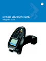
Symbol MT2070/MT2090
Integrator Guide
Symbol MT2070/MT2090
Integrator Guide
72E-117858-03
Revision A
October 2009
ii
Symbol MT2070/MT2090 Integrator Guide
© 2009 by Motorola, Inc. All rights reserved.
No part of this publication may be reproduced or used in any form, or by any electrical or mechanical means,
without permission in writing from Motorola. This includes electronic or mechanical means, such as
photocopying, recording, or information storage and retrieval systems. The material in this manual is subject to
change without notice.
The software is provided strictly on an “as is” basis. All software, including firmware, furnished to the user is on
a licensed basis. Motorola grants to the user a non-transferable and non-exclusive license to use each
software or firmware program delivered hereunder (licensed program). Except as noted below, such license
may not be assigned, sublicensed, or otherwise transferred by the user without prior written consent of
Motorola. No right to copy a licensed program in whole or in part is granted, except as permitted under
copyright law. The user shall not modify, merge, or incorporate any form or portion of a licensed program with
other program material, create a derivative work from a licensed program, or use a licensed program in a
network without written permission from Motorola. The user agrees to maintain Motorola’s copyright notice on
the licensed programs delivered hereunder, and to include the same on any authorized copies it makes, in
whole or in part. The user agrees not to decompile, disassemble, decode, or reverse engineer any licensed
program delivered to the user or any portion thereof.
Motorola reserves the right to make changes to any software or product to improve reliability, function, or
design.
Motorola does not assume any product liability arising out of, or in connection with, the application or use of
any product, circuit, or application described herein.
No license is granted, either expressly or by implication, estoppel, or otherwise under any Motorola, Inc.,
intellectual property rights. An implied license only exists for equipment, circuits, and subsystems contained in
Motorola products.
MOTOROLA and the Stylized M Logo and Symbol and the Symbol logo are registered in the US Patent &
Trademark Office. Bluetooth is a registered trademark of Bluetooth SIG. Microsoft, Windows and ActiveSync
are either registered trademarks or trademarks of Microsoft Corporation. All other product or service names
are the property of their respective owners.
Motorola, Inc.
One Motorola Plaza
Holtsville, New York 11742-1300
http://www.motorola.com/enterprisemobility
Patents
This product is covered by one or more of the patents listed on the Web site:
http://www.motorola.com/enterprisemobility/patents.
Warranty
For the complete Motorola hardware product warranty statement, go to:
http://www.motorola.com/enterprisemobility/warranty.
iii
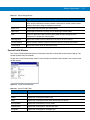
Revision History
Changes to the original manual are listed below:
Change
Date
Description
-01 Rev A
8/2009
Initial Release.
-02 Rev A
9/2009
Final engineering review.
-03 Rev A
10/2009
Tumble tech spec update.
iv
Symbol MT2070/MT2090 Integrator Guide
Table of Contents
Patents.................................................................................................................................................. ii
Warranty ............................................................................................................................................... ii
Revision History .................................................................................................................................... iii
About This Guide
Introduction ...........................................................................................................................................
Documentation Set .........................................................................................................................
Configurations.................................................................................................................................
Cradle Configurations .....................................................................................................................
Chapter Descriptions ............................................................................................................................
Notational Conventions.........................................................................................................................
Related Documents ..............................................................................................................................
Service Information...............................................................................................................................
xiii
xiii
xiv
xiv
xv
xv
xvi
xvii
Chapter 1: Getting Started
Introduction ..........................................................................................................................................
Unpacking ............................................................................................................................................
MT20X0 .........................................................................................................................................
Cradles ...........................................................................................................................................
STB2000-C10007R Single Slot Charge Only ..........................................................................
STB2000-F10007R Forklift Single Slot Charge Only ...............................................................
STB2078-C10007WR Single Slot Multi-interface Bluetooth ....................................................
STB2000-C40007R Four Slot Charge Only .............................................................................
STB2000-C40017R Four Slot Ethernet ...................................................................................
SAC2000-4000CR Four Slot Spare Battery Charger ...............................................................
Accessories .........................................................................................................................................
Features ...............................................................................................................................................
Keypad .................................................................................................................................................
Keypad Modes ...............................................................................................................................
Numeric Mode ..........................................................................................................................
Alphabetic Mode ......................................................................................................................
Function Key Mode ..................................................................................................................
ALT/CTRL Plus Character .......................................................................................................
1-1
1-1
1-1
1-1
1-1
1-1
1-2
1-2
1-2
1-2
1-2
1-3
1-4
1-6
1-6
1-6
1-6
1-6
vi
Symbol MT2070/MT2090 Integrator Guide
Keypad Mapping ............................................................................................................................
Host Interfaces .....................................................................................................................................
Quick Startup .......................................................................................................................................
Insert the Battery ............................................................................................................................
Battery Charging ..................................................................................................................................
Charging LEDs ....................................................................................................................................
Start Up ................................................................................................................................................
Resetting ..............................................................................................................................................
Performing a Warm Boot ...............................................................................................................
Performing a Cold Boot ..................................................................................................................
Waking the Device ...............................................................................................................................
Li-ion Battery Removal ........................................................................................................................
Customizing the Device Startup Program ............................................................................................
Spare Battery Charging .......................................................................................................................
Lanyard ................................................................................................................................................
1-7
1-11
1-12
1-12
1-13
1-14
1-14
1-15
1-15
1-15
1-16
1-16
1-17
1-17
1-17
Chapter 2: Accessories
Introduction ..........................................................................................................................................
Cradles ...........................................................................................................................................
Battery Charger ..............................................................................................................................
Cables ............................................................................................................................................
Intellistand ......................................................................................................................................
Other Accessories ..........................................................................................................................
Unpacking ............................................................................................................................................
Single Slot Cradles ..............................................................................................................................
Configurations ................................................................................................................................
Cradle Features .............................................................................................................................
Front View and Connections ....................................................................................................
Back View ................................................................................................................................
Mounting Cups .........................................................................................................................
Cradle Accessories ........................................................................................................................
Supplying Power to the Cradle ......................................................................................................
Using the USB Interface to Supply Power ...............................................................................
Connecting the STB20XX Cradle ..................................................................................................
Battery Charging in the Cradle .......................................................................................................
Changing the Host Interface ..........................................................................................................
Communication ..............................................................................................................................
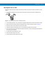
Sending Data to the Host Computer ........................................................................................
LED Indicators ...............................................................................................................................
Miscellaneous LED Indicator Information ................................................................................
Mounting ..............................................................................................................................................
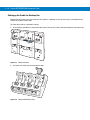
Horizontal (Desk) Mount ................................................................................................................
Vertical (Wall) Mount ......................................................................................................................
Forklift Single Slot Charge Only Cradle .........................................................................................
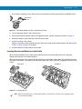
Attach the Mounting Bracket ....................................................................................................
Mounting the STB2000-F on the Forklift ..................................................................................
Four Slot Cradles .................................................................................................................................
Configurations ................................................................................................................................
Accessories ....................................................................................................................................
2-1
2-1
2-1
2-2
2-2
2-2
2-2
2-3
2-3
2-4
2-4
2-5
2-6
2-6
2-7
2-7
2-7
2-8
2-8
2-8
2-8
2-9
2-9
2-10
2-10
2-10
2-13
2-13
2-14
2-15
2-15
2-15
Table of Contents
Cradle Features .............................................................................................................................
Front .........................................................................................................................................
Back .........................................................................................................................................
Four Slot Charge Only Cradle Connections ...................................................................................
Ethernet Cradle Connections .........................................................................................................
Daisy Chaining .........................................................................................................................
Locating the Device IP Address .....................................................................................................
Mounting the Cradle on a Wall .......................................................................................................
Setting up the Cradle for Desktop Use ..........................................................................................
Inserting Devices and Batteries in the Cradle ................................................................................
Sending Data to the Host Computer ..............................................................................................
Charging ........................................................................................................................................
LED Indicators ...............................................................................................................................
Four Slot Battery Charger ....................................................................................................................
Accessories ....................................................................................................................................
Battery Charger Features ..............................................................................................................
Front ...............................................................................................................................................
Back ...............................................................................................................................................
Mounting ........................................................................................................................................
Inserting Batteries ..........................................................................................................................
Charging Batteries .........................................................................................................................
LED Indicators ...............................................................................................................................
Troubleshooting ...................................................................................................................................
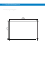
Wall Mount Templates .........................................................................................................................
vii
2-16
2-16
2-17
2-17
2-17
2-18
2-18
2-19
2-20
2-21
2-22
2-22
2-22
2-23
2-23
2-23
2-23
2-24
2-24
2-25
2-25
2-25
2-26
2-26
Chapter 3: ActiveSync
Introduction ..........................................................................................................................................
Setup ...................................................................................................................................................
Installing ActiveSync ............................................................................................................................
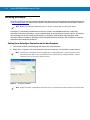
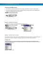
Setting Up an ActiveSync Connection on the Host Computer .......................................................
3-1
3-1
3-2
3-2
Chapter 4: Software Installation on Development PC
Introduction ..........................................................................................................................................
Required System Configurations .........................................................................................................
DCP for MT2070/MT2090 ....................................................................................................................
Installing .........................................................................................................................................
Components ...................................................................................................................................
Platform SDK .......................................................................................................................................
Enterprise Mobility Developer Kit .........................................................................................................
Installing Other Development Software ...............................................................................................
4-1
4-2
4-2
4-2
4-3
4-4
4-5
4-5
viii
Symbol MT2070/MT2090 Integrator Guide
Chapter 5: Software Installation on the MT20X0
Introduction ..........................................................................................................................................
ActiveSync ...........................................................................................................................................
Updating the Operating System ...........................................................................................................
Using IPL .......................................................................................................................................
Using ActiveSync ...........................................................................................................................
Using Airbeam ...............................................................................................................................
Adding Programs .................................................................................................................................
IPL .......................................................................................................................................................
5-1
5-1
5-3
5-3
5-3
5-3
5-4
5-4
Chapter 6: Creating/Loading Hex Images
Introduction ..........................................................................................................................................
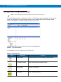
Starting Terminal Configuration Manager ............................................................................................
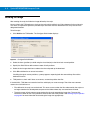
Defining Script Properties ....................................................................................................................
Creating the Script for the Hex Image .................................................................................................
Opening a New or Existing Script ..................................................................................................
Updating TCM 1.X Scripts .............................................................................................................
Copying Components to the Script ................................................................................................
Saving the Script ............................................................................................................................
Building the Image ...............................................................................................................................
Downloading the Hex Image ................................................................................................................
Using a USB Connection ...............................................................................................................
TCM Error Messages ...........................................................................................................................
IPL Error Detection ..............................................................................................................................
Creating a Splash Screen ....................................................................................................................
Splash Screen Format ...................................................................................................................
Flash Storage ......................................................................................................................................
FFS Partitions ................................................................................................................................
Working with FFS Partitions ...........................................................................................................
Non-FFS Partitions ........................................................................................................................
Downloading Partitions to the Device ............................................................................................
IPL .......................................................................................................................................................
Partition Update vs. File Update ....................................................................................................
Upgrade Requirements ..................................................................................................................
6-1
6-2
6-4
6-5
6-5
6-5
6-5
6-5
6-6
6-7
6-7
6-10
6-11
6-14
6-14
6-14
6-14
6-15
6-16
6-16
6-17
6-17
6-17
Chapter 7: Wireless Applications
Introduction ..........................................................................................................................................
Signal Strength Icon ............................................................................................................................
Turning Off the Radio (MT2090 only) ..................................................................................................
Find WLANs Application ......................................................................................................................
Profile Editor Wizard ............................................................................................................................
Profile ID ........................................................................................................................................
Operating Mode .............................................................................................................................
Ad-Hoc ...........................................................................................................................................
Authentication ................................................................................................................................
Tunneled Authentication ................................................................................................................
User Certificate Selection ..............................................................................................................
User Certificate Installation ......................................................................................................
7-1
7-2
7-3
7-4
7-5
7-5
7-6
7-7
7-8
7-9
7-11
7-11
Table of Contents
Server Certificate Selection ...........................................................................................................
Credential Cache Options ..............................................................................................................
User Name ...............................................................................................................................
Password .......................................................................................................................................
Advanced Identity ..........................................................................................................................
Encryption ......................................................................................................................................
Key Entry Page ..............................................................................................................................
Passkey Dialog ........................................................................................................................
IP Mode ..........................................................................................................................................
IP Address Entry ............................................................................................................................
Transmit Power ..............................................................................................................................
Battery Usage ................................................................................................................................
Manage Profiles Application ..........................................................................................................
Changing Profiles .....................................................................................................................
Editing a Profile ........................................................................................................................
Creating a New Profile .............................................................................................................
Deleting a Profile ......................................................................................................................
Ordering Profiles ......................................................................................................................
Export a Profile ........................................................................................................................
Wireless Status Application .................................................................................................................
Signal Strength Window .................................................................................................................
Current Profile Window ..................................................................................................................
IPv4 Status Window .......................................................................................................................
Wireless Log Window ....................................................................................................................
Saving a Log ............................................................................................................................
Clear the Log ...........................................................................................................................
Versions Window ...........................................................................................................................
Wireless Diagnostics Application .........................................................................................................
ICMP Ping Window ........................................................................................................................
Trace Route Window .....................................................................................................................
Known APs Window .......................................................................................................................
Options ................................................................................................................................................
Operating Mode Filtering ...............................................................................................................
Regulatory Options ........................................................................................................................
Band Selection ...............................................................................................................................
System Options ..............................................................................................................................
Change Password Dialog Box .......................................................................................................
Export .............................................................................................................................................
Cold Boot Persistence .........................................................................................................................
Registry Settings ..................................................................................................................................
Login, Log Off Application ....................................................................................................................
User Already Logged In .................................................................................................................
No User Logged In .........................................................................................................................
BTExplorer ...........................................................................................................................................
ix
7-12
7-13
7-15
7-15
7-16
7-16
7-18
7-18
7-19
7-19
7-21
7-22
7-23
7-24
7-24
7-24
7-24
7-24
7-24
7-25
7-26
7-27
7-28
7-29
7-29
7-29
7-30
7-31
7-32
7-32
7-33
7-34
7-34
7-35
7-35
7-36
7-36
7-37
7-38
7-39
7-40
7-40
7-40
7-42
x
Symbol MT2070/MT2090 Integrator Guide
Chapter 8: Staging and Provisioning
Introduction ..........................................................................................................................................
Staging .................................................................................................................................................
RD Client Version 3.28 ..................................................................................................................
Bar Code Scanning ........................................................................................................................
On-Demand Staging ......................................................................................................................
ActiveSync Connection Mode ..................................................................................................
Ethernet Cradle Connection Mode ...........................................................................................
Already existing IP Connection Mode ......................................................................................
Well-known WLAN Connection Mode ......................................................................................
RD Client Main Menu .....................................................................................................................
Client Info .................................................................................................................................
Log Menu .................................................................................................................................
View Log ..................................................................................................................................
View Job Log ...........................................................................................................................
Set Log Level ...........................................................................................................................
Set Job Log Level ....................................................................................................................
Package List ............................................................................................................................
Provisioning .........................................................................................................................................
MSP Agent .....................................................................................................................................
MSP Agent Main Menu ............................................................................................................
AirBEAM Smart Client ....................................................................................................................
AirBEAM Package Builder .......................................................................................................
AirBEAM Smart Client ..............................................................................................................
AirBEAM Smart Staging ......................................................................................................................
8-1
8-1
8-1
8-2
8-4
8-4
8-4
8-4
8-4
8-6
8-6
8-7
8-8
8-8
8-9
8-9
8-10
8-11
8-11
8-11
8-17
8-17
8-17
8-25
Chapter 9: Maintenance and Troubleshooting
Introduction ..........................................................................................................................................
Maintenance ........................................................................................................................................
MT20X0 .........................................................................................................................................
Battery ............................................................................................................................................
Cradles ...........................................................................................................................................
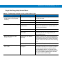
Troubleshooting ...................................................................................................................................
MT20X0 .........................................................................................................................................
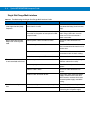
Single Slot Charge Only Cradle .....................................................................................................
Single Slot Charge Only Vehicle Mount .........................................................................................
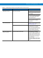
Single Slot Charge Multi-interface .................................................................................................
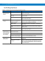
Four Slot Charge Only Ethernet .....................................................................................................
Four Slot Charge Only Cradle ........................................................................................................
Four Slot Spare Battery Charger ...................................................................................................
Cables ............................................................................................................................................
9-1
9-1
9-1
9-2
9-2
9-3
9-3
9-6
9-7
9-8
9-10
9-11
9-12
9-13
Table of Contents
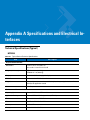
Appendix A: Specifications and Electrical Interfaces
Technical Specifications (Typical) .......................................................................................................
MT20X0 .........................................................................................................................................
Single Slot Charge Only Cradle .....................................................................................................
Single Slot Charge Only Vehicle Cradle ........................................................................................
Single Slot Charge Multi-interface Bluetooth Cradle ......................................................................
Four Slot Charge Ethernet Cradle .................................................................................................
Four Slot Charge Only Cradle ........................................................................................................
Four Slot Spare Battery Charger ...................................................................................................
MT2000 Series Electrical Interface/Device Pin-Outs ...........................................................................
Device Interface to Cradle .............................................................................................................
Device Interface to Cable ...............................................................................................................
Auxiliary Connection ......................................................................................................................
Index
Glossary
xi
A-1
A-1
A-4
A-5
A-6
A-7
A-8
A-9
A-10
A-10
A-11
A-12
xii
Symbol MT2070/MT2090 Integrator Guide
About This Guide
Introduction
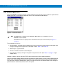
This guide provides information about using the Symbol MT2070/MT2090 devices.
NOTE
Screens and windows pictured in this guide are samples and can differ from actual screens.
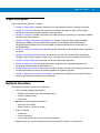
Documentation Set
The documentation set for the Symbol MT2070/MT2090 devices provides information for specific user needs, and
includes:
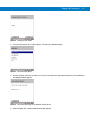
• MT2070/ MT2090 Quick Start Guide - describes how to get the device up and running (p/n 72-117308-xx).
• MT2070/ MT2090 User Guide - describes how to use the device (p/n 72E-117859-xx).
• MT2070/ MT2090 Integrator Guide - describes how to set up the device and accessories (72E-117858-xx).
• Enterprise Mobility Developer Kit (EMDK) Help File - provides API information for writing applications.
xiv
Symbol MT2070/MT2090 Integrator Guide
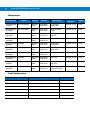
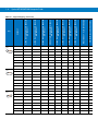
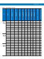
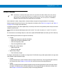
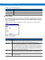
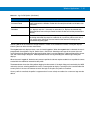
Configurations
Configuration
Radios
Display
Memory
Operating
System
Data Capture
Keypads
MT2090-SL0D6
2170WR
802.11/Bluetooth
320x240
Color
64 MB RAM
64 MB Flash
1D, Standard
Range, WW
Windows CE 5.0
21 key
MT2090-SD0D
62170WR
802.11/Bluetooth
320x240
Color
64 MB RAM
64 MB Flash
1D/2D, Standard
Range
Windows CE 5.0
21 key
MT2090-HD0D
62170WR
802.11/Bluetooth
320x240
Color
64 MB RAM
64 MB Flash
1D/2D, High
Definition
Windows CE 5.0
21 key
MT2090-DP0D
62170WR
802.11/Bluetooth
320x240
Color
64 MB RAM
64 MB Flash
DPM
Windows CE 5.0
21 key
MT2070-SL0D6
2370WR
Bluetooth
320x240
Color
64 MB RAM
64 MB Flash
1D, Standard
Range, MCL
Windows CE 5.0
21 key
MT2070-SD0D
62370WR
Bluetooth
320x240
Color
64 MB RAM
64 MB Flash
1D/2D,Standard
Range, MCL
Windows CE 5.0
21 key
MT2070-HD0D
62370WR
Bluetooth
320x240
Color
64 MB RAM
64 MB Flash
1D/2D, HD, MCL
Windows CE 5.0
21 key
MT2070-DP0D
62370WR
Bluetooth
320x240
Color
64 MB RAM
64 MB Flash
DPM, MCL
Windows CE 5.0
21 key
MT2070-SL1D6
2370WR
Bluetooth
320x240
Color
64 MB RAM
64 MB Flash
Standard Range,
EAS, MCL
Windows CE 5.0
21 key
MT2070-SD0D
62370WR
Bluetooth
320x240
Color
64 MB RAM
64 MB Flash
1D/2D, Standard
Range, EAS, MCL
Windows CE 5.0
21 key
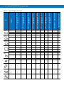
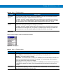
Cradle Configurations
Cradle Configuration
Type
Radio
STB2000-C10007R
Single Slot, Charge Only
N/A
STB2000-F10007R
Single Slot, Charge Only, Vehicle Mount
N/A
STB2000-C10007WR
Single Slot, Charge, Multi-interface
Bluetooth
STB2000-C40007R
Four Slot, Charge Only
Bluetooth
STB2000-C40017R
Four Slot, Charge Only
Ethernet
SAC2000-4000CR charger
Four bay spare battery charger
N/A
About This Guide
xv
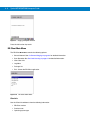
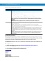
Chapter Descriptions
Topics covered in this guide are as follows:
• Chapter 1, Getting Started, provides information on charging the device battery, resetting and keypad.
• Chapter 2, Accessories, describes the accessories available for the device and how to set up power
connections and battery charging capabilities, where applicable.
• Chapter 3, ActiveSync, provides instructions on installing ActiveSync and setting up a partnership between
the device and a host computer.
• Chapter 4, Software Installation on Development PC, provides information about Enterprise Mobility
Developer Kit (EMDK) for C for both WinCE 4.2 and Win CE 5.0; Windows CE Platform SDK for
MT2070/MT2090 or Windows CE 5.0 standard SDK; and, Device Configuration Package (DCP) for
MT2070/MT2090.
• Chapter 5, Software Installation on the MT20X0, provides information for downloading software and files to
the device.
• Chapter 6, Creating/Loading Hex Images, describes how to install and use the Terminal Configuration
Manager (TCM) and Initial Program Loader (IPL) to customize flash file system partitions for the device.
• Chapter 7, Wireless Applications, describes the Wireless Companion application.
• Chapter 8, Staging and Provisioning, describes how to stage devices using Rapid Deployment and
provisioning using MSP Agent or AirBEAM Smart.
• Chapter 9, Maintenance and Troubleshooting, includes instructions on cleaning and storing the device, and
provides troubleshooting solutions for potential problems during device operation.
• Chapter A, Specifications and Electrical Interfaces, includes electrical specifications and tables listing the
technical specifications for the device and accessories.
Notational Conventions
The following conventions are used in this document:
• Italics are used to highlight the following:
• Chapters and sections in this and related documents
• Screen or window names
• Field names
• Bold text is used to highlight the following:
• Key names on a keypad
• Button names on a screen or window.
• bullets (•) indicate:
• Action items
• Lists of alternatives
• Lists of required steps that are not necessarily sequential
• Sequential lists (e.g., those that describe step-by-step procedures) appear as numbered lists.
xvi
Symbol MT2070/MT2090 Integrator Guide
NOTE
This symbol indicates something of special interest or importance to the reader. Failure to read the note
will not result in physical harm to the reader, equipment or data.
CAUTION
This symbol indicates that if this information is ignored, the possibility of data or material damage may
occur.
WARNING!
This symbol indicates that if this information is ignored the possibility that serious personal
injury may occur.
Related Documents
The following documents provide more information about the MT2070/MT2090 devices.
• MT2070/MT2090 Quick Start Guide (p/n 72-117308-xx) - describes how to get the device up and running.
• MT2070/MT2090 User Guide, p/n 72E-117859-xx - describes how to use the device.
• Symbol STB2000 Cradle Quick Reference Guide (p/n 72-xxxxx-xx) - describes how to install and operate the
cradles.
• Symbol SAC2000 Cradle Quick Reference Guide (p/n 72-xxxxx-xx) - describes how to install and operate the
charger.
For the latest version of this guide and all guides, go to: http://www.motorola.com/enterprisemobility/manuals.
About This Guide
xvii
Service Information
If you have a problem with your equipment, contact Motorola Enterprise Mobility support for your region. Contact
information is available at: http:///www.motorola.com/enterprisemobility/contactsupport.
When contacting Enterprise Mobility support, please have the following information available:
• Serial number of the unit
• Model number or product name
• Software type and version number
Motorola responds to calls by E-mail, telephone or fax within the time limits set forth in support agreements.
If your problem cannot be solved by Motorola Enterprise Mobility Support, you may need to return your equipment
for servicing and will be given specific directions. Motorola is not responsible for any damages incurred during
shipment if the approved shipping container is not used. Shipping the units improperly can possibly void the
warranty.
If you purchased your Enterprise Mobility business product from a Motorola business partner, contact that business
partner for support.
xviii
Symbol MT2070/MT2090 Integrator Guide
Chapter 1 Getting Started
Introduction
This chapter provides information about the device, accessories, charging the device and resetting the device.
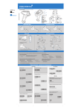
Unpacking
Carefully remove all protective material from around the equipment and inspect it for damage. If the equipment was
damaged in transit, contact Motorola Enterprise Mobility Support. See page xvii for contact information. KEEP THE
PACKING. It is the approved shipping container and should be used if the equipment ever needs to be returned for
servicing.
MT20X0
Verify that the equipment listed below is included in the box:
• MT2070/MT2090 device
• Lithium-ion (Li-ion) battery
• Quick Start Guide.
Cradles
STB2000-C10007R Single Slot Charge Only
Verify that the equipment listed below is included in the box:
• Cradle with desk mount cup installed
• Wall mount cup
• Regulatory Guide.
1-2
Symbol MT2070/MT2090 Integrator Guide
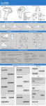
STB2000-F10007R Forklift Single Slot Charge Only
Verify that the equipment listed below is included in the box:
• Cradle with forklift cup installed
• Metal mounting bracket with isolators
• Quick Reference Guide.
STB2078-C10007WR Single Slot Multi-interface Bluetooth
Verify that the equipment listed below is included in the box:
• Cradle with desk mount cup installed
• Wall mount cup
• Quick Reference Guide.
STB2000-C40007R Four Slot Charge Only
Verify that the equipment listed below is included in the box:
• Cradle with wall mount cups installed
• Quick Reference Guide.
STB2000-C40017R Four Slot Ethernet
Verify that the equipment listed below is included in the box:
• Cradle with wall mount cups installed
• Quick Reference Guide.
SAC2000-4000CR Four Slot Spare Battery Charger
Verify that the equipment listed below is included in the box:
• Charger
• Quick Reference Guide.
Accessories
See Chapter 2, Accessories for a list all accessories available for the MT2070/MT2090 devices.
Getting Started
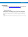
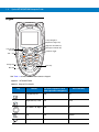
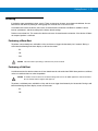
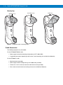
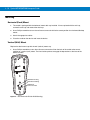
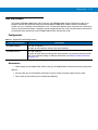
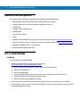
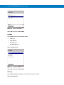
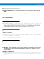
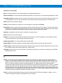
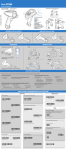
Features
Scan LED
Display
Keypad
Scan LED
(MT2090
only)
Scan LED
(MT2090 only)
Scan
Window
* Accessory Port
Cover
Scan Trigger
Battery
Battery Latch
* Note: The accessory port is not available for use at this
time. The device is not water sealed if the accessory port
cover is removed.
Lanyard
Catch
Beeper
WARNING!
Never connect an Ethernet or
phone cable to the host interface
port.
Charge/Communication Contacts
Hook Recesses for Wall Mount Cradle
Figure 1-1 MT2070/MT2090
1-3
1-4
Symbol MT2070/MT2090 Integrator Guide
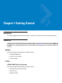
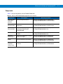
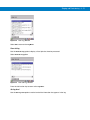
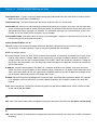
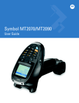
Keypad
4-way Navigation
(Up, Down, Right, Left)
Right soft and CTRL key
ALT
Left soft and
ALT key
Tab - * key
CTRL
F
F
4 GHI
F
7 PQRS
Cold boot trigger
ESC
TAB
DEF
F
2
ABC
F
3
F
5
JKL
F
6 MNO
F
8
TUV
F
Orange key
0
Backspace and ESC key
9 WXVZ
ENT
Enter key
Blue key
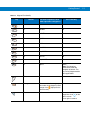
See Table 1-1 for detailed information about the keypad.
Figure 1-2 MT2070/MT2090
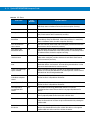
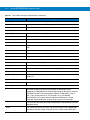
Table 1-1 Keypad Functionality
Key
Default
Press Orange Key
(For letter sequences, each
letter represents a key press.)
Press Blue Key
Left Soft Key, ALT
N/A
ALT
Right Soft Key; CTRL
N/A
CTRL
Up, Down, Left, Right
N/A
n/a
Tab
N/A
Asterisk
Backspace
N/A
ESC
ALT
CTRL
TAB
ESC
Getting Started
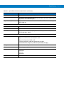
Table 1-1 Keypad Functionality
Key
F
2
F
3
F
ABC
DEF
F
4 GHI
F
5
JKL
6 MNO
F
F
7 PQRS
F
8
F
TUV
9 WXVZ
0
Default
Press Orange Key
(For letter sequences, each
letter represents a key press.)
Press Blue Key
1
.,-/
F1
2
abcABC
F2
3
defDEF
F3
4
ghiGHI
F4
5
jklJKL
F5
6
mnoMNO
F6
7
pqrsPQRS
F7
8
tuvTUV
F8
9
wxyzWXYZ
F9
0
Space
Home
Note: The Home key
automatically loads the
Navigator by default. This
key can be programmed for
other applications.
Enter
N/A
N/A
Orange
Press to enable the orange
characters on the keypad (a filled
N/A
ENT
orange circle
device screen).
Blue
N/A
displays on the
Press once to display an
empty blue circle
on the
device screen.
Press again to remove.
1-5
1-6
Symbol MT2070/MT2090 Integrator Guide
Keypad Modes
Numeric Mode
Numeric mode is the keypad default. When the keypad is not in CTRL, ALT or Alpha mode (i.e., the Orange key is
not enabled), each numeric key represents its associated number and no multi-tapping a key is required.
Alphabetic Mode
The keypad goes into alphabetic (alpha) mode when the orange key is pressed and remains in alpha mode until
the orange key is pressed a second time. A solid orange dot appears in the device display when alpha mode is
active and disappears when it is turned off.
In this mode, multi-tapping a key generates the letters on the respective key; lower case letters first, followed by
upper case letters. For example, in alpha mode the '2' key cycles through 'a', 'b', 'c', 'A', 'B', and 'C' depending on
the number of taps.
Function Key Mode
The keypad goes into function key mode when the blue key is pressed. ‘F’ keys, displayed on the keypad in blue,
are accessible in un-shifted mode only (when alpha mode is off). If the keypad is currently in alpha mode (an
orange dot appears in the device display) and 'F1' is required, press the orange key to exit alpha mode and return
to un-shifted mode; press the blue key; press the appropriate number key (e.g., press number '1' for 'F1', press
number '2' for 'F2', etc.).
ALT/CTRL Plus Character
Some applications support shortcut keys (hot keys), such as ALT+F, CTRL+C.
To use shortcut key combinations:
1.
In un-shifted mode, press the blue key one time.
2.
Press the left soft key (ALT) or right soft key (CTRL).
3.
Press the orange key to enter alpha mode.
4.
Multi-tap the appropriate key to select the desired letter (e.g., multi-tap the ‘3’ key three times to select lower
case 'f').
5.
Press the orange key again to exit alpha mode.
When the orange key is pressed the second time to exit alpha mode, the key combination generates (e.g., ALT+F).
The blue key is automatically released after exiting the alpha mode.
Key
F1 . , - /
F2 2 A B C
abc
F
F
2
F3 3 D E F
def
3
F
SC_1KEY
SC_PERIOD
SC_COMMAKEY
SC_MINUS
SC_FSLASH
F1
SC_2KEY
SC_AKEY
SC_BKEY
SC_CKEY
SC_AKEY
SC_BKEY
SC_CKEY
F2
SC_3KEY
SC_DKEY
SC_EKEY
SC_FKEY
SC_DKEY
SC_EKEY
SC_FKEY
F3
HEX-DECIMAL SCAN CODE VALUE
FUNCTION KEY - -BLUE KEY ENABLED
ALPHA STATE - ORANGE KEY ENBALED
(KEY PRESS 7)
ALPHA STATE - ORANGE KEY ENBALED
(KEY PRESS 6)
ALPHA STATE - ORANGE KEY ENBALED
(KEY PRESS 5)
ALPHA STATE - ORANGE KEY ENBALED
(KEY PRESS 1)
ALPHA STATE - ORANGE KEY DISBALED
(KEY PRESS 4)
ALPHA STATE - ORANGE KEY ENBALED
(KEY PRESS 3)
ALPHA STATE - ORANGE KEY ENBALED
(KEY PRESS 2)
ALPHA STATE - ORANGE KEY ENBALED
(KEY PRESS 1)
DEFAULT
Getting Started
1-7
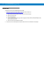
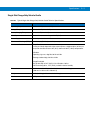
Keypad Mapping
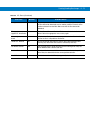
Table 1-2 Keypad Mapping
0x02
0x34
0x33
0x0c
0x35
0x3b
0x03
ABC
0x1e
0x30
0x2e
0x1e
0x30
0x2e
0x3c
0x04
DEF
0x20
0x12
0x21
0x20
0x12
0x21
0x3d
Key
F4 4 G H I
ghi
F
F5 5 J K L
jkl
F
F
5
F6 6 M N O
mno
JKL
SC_4KEY
SC_GKEY
SC_HKEY
SC_IKEY
SC_GKEY
SC_HKEY
SC_IKEY
F4
SC_5KEY
SC_JKEY
SC_KKEY
SC_LKEY
SC_JKEY
SC_KKEY
SC_LKEY
F5
SC_6KEY
SC_MKEY
SC_NKEY
SC_OKEY
SC_MKEY
SC_NKEY
SC_OKEY
F6
HEX-DECIMAL SCAN CODE VALUE
FUNCTION KEY - -BLUE KEY ENABLED
ALPHA STATE - ORANGE KEY ENBALED
(KEY PRESS 7)
ALPHA STATE - ORANGE KEY ENBALED
(KEY PRESS 6)
ALPHA STATE - ORANGE KEY ENBALED
(KEY PRESS 5)
ALPHA STATE - ORANGE KEY ENBALED
(KEY PRESS 1)
ALPHA STATE - ORANGE KEY DISBALED
(KEY PRESS 4)
ALPHA STATE - ORANGE KEY ENBALED
(KEY PRESS 3)
ALPHA STATE - ORANGE KEY ENBALED
(KEY PRESS 2)
ALPHA STATE - ORANGE KEY ENBALED
(KEY PRESS 1)
DEFAULT
1-8
Symbol MT2070/MT2090 Integrator Guide
Table 1-2 Keypad Mapping (Continued)
0x05
4 GHI
0x22
0x23
0x17
0x22
0x23
0x17
0x3e
0x06
0x24
0x25
0x26
0x24
0x25
0x26
0x3f
0x07
6 MNO
0x32
0x31
0x18
0x32
0x31
0x18
0x40
Key
F7 7 P Q R
Spqrs
F
F8 8 T U V
tuv
F
F
8
F9 9 W X Y
Zwxyz
9 WXVZ
SC_7KEY
SC_PKEY
SC_QKEY
SC_RKEY
SC_SKEY
SC_PKEY
SC_QKEY
SC_RKEY
SC_SKEY
F7
SC_8KEY
SC_TKEY
SC_UKEY
SC_VKEY
SC_TKEY
SC_UKEY
SC_VKEY
F8
SC_9KEY
SC_WKEY
SC_XKEY
SC_YKEY
SC_ZKEY
SC_WKEY
SC_XKEY
SC_YKEY
SC_ZKEY
F9
HEX-DECIMAL SCAN CODE VALUE
FUNCTION KEY - -BLUE KEY ENABLED
ALPHA STATE - ORANGE KEY ENBALED
(KEY PRESS 7)
ALPHA STATE - ORANGE KEY ENBALED
(KEY PRESS 6)
ALPHA STATE - ORANGE KEY ENBALED
(KEY PRESS 5)
ALPHA STATE - ORANGE KEY ENBALED
(KEY PRESS 1)
ALPHA STATE - ORANGE KEY DISBALED
(KEY PRESS 4)
ALPHA STATE - ORANGE KEY ENBALED
(KEY PRESS 3)
ALPHA STATE - ORANGE KEY ENBALED
(KEY PRESS 2)
ALPHA STATE - ORANGE KEY ENBALED
(KEY PRESS 1)
DEFAULT
Getting Started
1-9
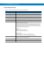
Table 1-2 Keypad Mapping (Continued)
0x08
7 PQRS
0x19
0x10
0x13
0x1f
0x19
0x10
0x13
0x1f
0x41
0x09
TUV
0x14
0x16
0x2f
0x14
0x16
0x2f
0x42
0x0a
0x11
0x2d
0x15
0x2c
0x11
0x2d
0x15
0x2c
0x43
1 - 10 Symbol MT2070/MT2090 Integrator Guide
Home 0
space
SC_0KEY
0x0b
SC_SPACEKEY
0
0x39
HOME
ALT
Left Soft
HEX-DECIMAL SCAN CODE VALUE
FUNCTION KEY - -BLUE KEY ENABLED
ALPHA STATE - ORANGE KEY ENBALED
(KEY PRESS 7)
ALPHA STATE - ORANGE KEY ENBALED
(KEY PRESS 6)
ALPHA STATE - ORANGE KEY ENBALED
(KEY PRESS 5)
ALPHA STATE - ORANGE KEY ENBALED
(KEY PRESS 1)
ALPHA STATE - ORANGE KEY DISBALED
(KEY PRESS 4)
ALPHA STATE - ORANGE KEY ENBALED
(KEY PRESS 3)
ALPHA STATE - ORANGE KEY ENBALED
(KEY PRESS 2)
ALPHA STATE - ORANGE KEY ENBALED
(KEY PRESS 1)
Key
DEFAULT
Table 1-2 Keypad Mapping (Continued)
SC_APP1
0x47
0x6a
SC_LALT
0x38
ALT
CTRL
Right Soft
SC_APP2
0x6b
SC_LCTRL
0x1d
CTRL
Navigation
Asterisk
TAB
SC_LEFTARROW
0x4b
SC_RIGHTARROW
0x4d
SC_UPARROW
0x48
SC_DOWNARROW
0x50
SC_TABKEY
0x0f
SC_ASTERIX
0x37
TAB
Escape
Backspace
SC_BACKSPACE
0x0e
SC_ESCAPEKEY
0x01
ESC
SC_ENTERKEY
0x1c
Orange
SC_ORANGEKEY
0x7e
Blue
SC_LCONTROL
0x61
Enter
ENT
Getting Started 1 - 11
Host Interfaces
This device supports the following host interfaces through communication with a single slot multi-interface cradle:
• Standard RS-232 connection to a host.
• Keyboard wedge connection to a host, where scanned data is interpreted as keystrokes. The following
international keyboards are supported (for Windows™ environment): North American, German, French,
French Canadian, Spanish, Italian, Swedish, UK English, Japanese, and Brazilian-Portuguese.
• IBM® 468X/469X hosts.
• USB connection to a host. The device autodetects a USB host and defaults to the HID keyboard interface
type. Select other USB interface types by scanning programming bar codes. Following is a sample of the
supported international keyboards for a Windows™ environment: North America, German, French, French
Canadian, Spanish, Italian, Swedish, UK English, Japanese and Brazilian Portuguese. For a complete list of
the supported international keyboards, refer to the MT2090/MT2070 User Guide (p/n 72E-117859-xx).
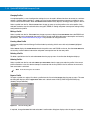
NOTE
USB interface types can also be selected via the USB configuration menu on the device. To access the
USB configuration menu from the device’s Home screen, select Config... > Configure USB.
This device supports the following host interfaces without communication with a cradle:
• Standard RS-232 connection to a host.
• USB connection to a host via Bluetooth technology. The device autodetects a USB host and defaults to the
HID keyboard interface type. Select other USB interface types by scanning programming bar codes.
Following is a sample of the supported international keyboards for a Windows™ environment: North
America, German, French, French Canadian, Spanish, Italian, Swedish, UK English, Japanese and Brazilian
Portuguese. For a complete list of the supported international keyboards, refer to the MT2090/MT2070 User
Guide (p/n 72E-117859-xx).
NOTE
USB interface types can also be selected via the USB configuration menu on the device. To access the
USB configuration menu from the device’s Home screen, select Config... > Configure USB.
1 - 12 Symbol MT2070/MT2090 Integrator Guide
Quick Startup
To get the MT2070/MT2090 up and running:
• Insert the rechargeable Li-ion battery
• Connect power to the cradle.
• Insert the device in the cradle.
• Charge the device.
• Configure the device.
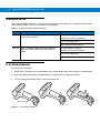
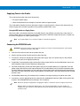
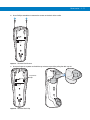
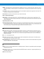
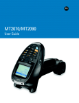
Insert the Battery
The battery resides in a chamber in the device handle.
NOTE
If the battery is completely discharged, and the unit is powered from a USB or RS232 cable, it may take up
to two hours for the unit to power up.There is no indication to the user of this condition and it may appear
that the unit is not charging and/or not working correctly. However, if the unit is placed in an STB2000
cradle with the 12V power supply power up is immediate.
To insert the battery:
1.
Insert the battery into the battery well, top first, ensuring that the battery connectors touch the device
connectors inside the well.
CAUTION
2.
Avoid touching the contacts when positioning the battery.
Push down on the back of the battery until it snaps into place.
Figure 1-3 Battery Insertion
Getting Started 1 - 13
Battery Charging
NOTE
If the battery is completely discharged, and the unit is powered from a USB or RS232 cable, it may take up
to two hours for the unit to power up.There is no indication to the user of this condition and it may appear
that the unit is not charging and/or not working correctly. However, if the unit is placed in an STB2000 or
STB2078 cradle with the 12V power supply power up is immediate.
Use the device’s cradles, charge cables, and spare battery chargers to charge the device’s Li-ion battery.
Before using the device for the first time, fully charge the main battery. (See Table 2-2 on page 2-9 and Table 2-7
on page 2-22 for charge status indications.)
A complete charge of a fully discharged battery can take up to four hours using external power and up to 10 hours
using the interface cable.
Charge within the recommended temperature of 32° to 104° F (0° to 40° C) nominal, 41° to 95° F (5° to 35° C)
ideal.
For information on maximizing battery life, refer to the Symbol MT2070/MT2090 User Guide (p/n 72E-117859-xx).
Use the following accessories to charge the Li-ion battery:
• Cradles:
• Single slot charge only cradle with ActiveSync
• Single slot multi-interface Bluetooth cradle
• Four slot charge only cradle
• Four slot charge/Ethernet cradle.
• Cables (and a power supply):
• USB charge cable
• RS-232 charge cable.
• Spare battery charger:
• Four slot battery charger.
To charge Li-ion batteries use a cradle or a charge cable. The RS-232 charge cable requires both the charge cable
and a Motorola approved power supply.
• Cradles
Insert the device into a cradle. The device starts to charge automatically. The charge LED lights to indicate
the charge status. See Chapter 2, Accessories for accessory setup and charging indications.
• Cables
Connect a charge cable to the appropriate power source and connect the other end of the charge cable to
the device. The device starts to charge automatically. The charge LED lights to indicate the charge status.
See Chapter 2, Accessories for accessory setup and charging indications.
1 - 14 Symbol MT2070/MT2090 Integrator Guide
Charging LEDs
The device’s green LED indicates charging activity when the device is seated in a cradle. Charge activity is also
indicated by the charge icon on the device display screen.
If the device’s red LED begins flashing, indicating a charging problem, remove the device from the cradle and
replace the battery. If the red LED continues flashing, contact Motorola Enterprise Mobility Support.
Refer to the Symbol MT2070/MT2090 User Guide (p/n 72E-117859-xx) for device and cradle LED indicators.
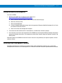
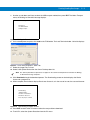
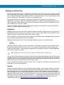
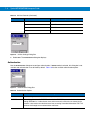
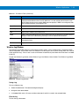
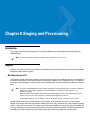
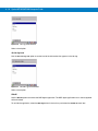
Start Up
When the device is powered on for the first time, it initializes. The splash screen appears for a short period of time.
If the device does not power on, see Resetting on page 1-15.
MT2000
series
Figure 1-4 Splash Screen
Getting Started 1 - 15
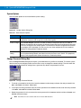
Resetting
If the device stops responding to input, reset it. There are two types of resets, warm boot and cold boot. A warm
boot restarts the device by closing all running programs. All data that is not saved is lost.
A cold boot also restarts the device, but erases all stored records and entries from RAM. In addition it returns
formats, preferences, and other settings to the factory default settings.
Perform a warm boot first. This restarts the device and saves all stored records and entries. If the device still does
not respond, perform a cold boot.
Performing a Warm Boot
To perform a warm boot press and hold the 2 key and the scan trigger simultaneously for 5 seconds. During a
warm boot the following three items display as text on the screen:
- IPL
- OS
- PM.
CAUTION
Files that remain open during a warm boot may not be retained.
Performing a Cold Boot
A cold boot restarts the device and erases all user stored records and entries from RAM. Never perform a cold boot
unless a warm boot does not solve the problem.
CAUTION
A cold boot resets the device to the default settings and removes all added applications and all stored data.
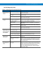
Do not cold boot without support desk approval.
To perform a cold boot press and hold the 2 key and the scan trigger simultaneously for 10 seconds. During a cold
boot the following two items display as text on the screen:
- IPL
- OS.
1 - 16 Symbol MT2070/MT2090 Integrator Guide
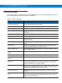
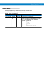
Waking the Device
The wakeup conditions define what actions wake up the device. These settings are configurable and the factory
default settings shown in Table 1-3 are subject to change/update.
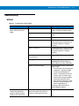
Table 1-3 Wakeup Conditions (Default Settings)
Status
Suspend
Description
When the device is set to the suspend mode these
actions wake the device.
Conditions for Wakeup
AC power is added or removed.
Cradle/cable connect or disconnect.
Key or scan trigger press.
Real Time Clock set to wake up.
Auto Off
When the automatic power-off function places the
device in suspend mode these actions wake the
device.
AC power added or removed.
Cradle/cable connect or disconnect.
Key or scan trigger press.
Real Time Clock set to wake up.
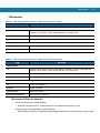
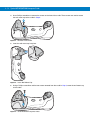
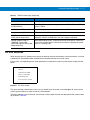
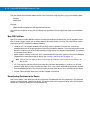
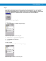
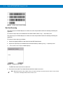
Li-ion Battery Removal
To remove the Li-ion battery:
1.
Select Menu > Suspend on the Home window to turn off the window and place the device in suspend mode.
2.
With your thumb, press down on the indentation on the battery lock and drag it backwards.
3.
Lift up the back of the battery and pull it out of the battery well.
Battery lock
Figure 1-5 Li-ion Battery Removal
Getting Started 1 - 17
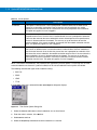
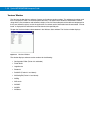
Customizing the Device Startup Program
For information about customizing the Startup.run file to alter the default startup application refer to the
MT2070/MT2090 User Guide, p/n 72E-117859-xx.
Spare Battery Charging
Use the Spare Battery charger to charge spare Li-ion batteries. See to Chapter 2, Accessories for more information
on spare battery charging.
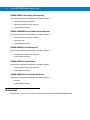
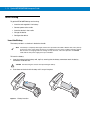
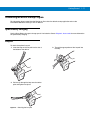
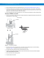
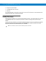
Lanyard
To attach the optional lanyard:
1. Insert the loop on the lanyard into the slot at
the bottom of the device.
3. Pull the clip through the loop over the tether
point and tighten into place.
Figure 1-6 Attaching the Lanyard
2. Thread the upper portion of the lanyard into
the loop.
1 - 18 Symbol MT2070/MT2090 Integrator Guide
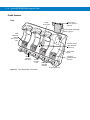
Chapter 2 Accessories
Introduction
The MT2070/MT2090 accessories provide a variety of product support capabilities. This chapter provides
information about cables, single slot cradles, multi-slot cradles and the four slot battery charger.
Cradles
• STB2000-C10007R single slot charge only cradle (with ActiveSync) charges the device’s Li-ion battery
installed in the device. It also synchronizes the device with a host computer using ActiveSync through a USB
connection.
• STB2078-C10007WR single slot multi-interface Bluetooth cradle charges the device’s Li-ion battery installed
in the device and, when the pairing bar code on the cradle is scanned, it pairs with the device allowing the
device and cradle to exchange information. Refer to the MT2090/MT2070 User Guide (p/n 72E-117859-xx)
for detailed information about pairing and Bluetooth technology.
NOTE
ActiveSync is not supported on this cradle.
• STB2000-F10007R forklift single slot charge only cradle charges the device’s Li-ion battery installed in the
device. The following accessories are not included but may be required: 9 Vdc, minimum 2A power supply for
forklift configuration (Motorola p/n 50-14000-122R); three 1.25" #8 Phillips head screws (for wall mounting, if
applicable, not available from Motorola).
• STB2000-C40007R four slot charge only cradle charges up to four spare batteries and up to four devices
with batteries installed.
• STB2000-C40017R four slot Ethernet cradle charges up to four spare batteries and up to four devices with
batteries installed. It also synchronizes up to four devices with a host computer through an Ethernet
connection. An Ethernet cable is required for communication (not available from Motorola).
• SAC2000-4000CR four slot spare battery charger charges up to four single batteries.
Battery Charger
• Four slot spare battery charger charges up to four spare batteries.
2-2
Symbol MT2070/MT2090 Integrator Guide
Cables
The following cables can connect to the device or single slot cradles:
• USB Client Charge Cable
• RS-232 Serial Cable with Power Supply.
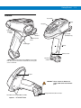
Intellistand
The Intellistand provides a hands-free method of scanning.
Other Accessories
• Lanyard
• Belt Holster.
Unpacking
Carefully remove all protective material from around the equipment and inspect it for damage. If the equipment was
damaged in transit, contact Motorola Enterprise Mobility Support. KEEP THE PACKING. It is the approved shipping
container and should be used if the equipment ever needs to be returned for servicing.
Accessories
2-3
Single Slot Cradles
The Symbol STB2000-C10007R, STB2078-C10007WR and STB2000-F10007R cordless device cradles act as
power pass throughs to the device and host communication interfaces for the Symbol MT2000 Series cordless
devices. Cradles can sit on a desktop, mount on a wall or mount on a forklift (STB2000-F only). Any discussion of
transmission of information refers specifically to cradles with Bluetooth technology.
NOTE
Use only a Motorola/Symbol approved power supply (50-14000-148R) output rated at 12 Vdc and minimum
3.3 A or DC to DC converter 50-14000-122R output rated at 9 Vdc and minimum 1.0 A.
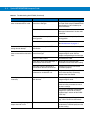
Configurations
Table 2-1 Single Slot Cradle Configurations
Cradle Configuration
Description
STB2000
Single slot, charge only.
Charge only cradles can communicate with a PC via ActiveSync by attaching a USB cable to
the USB connector.
STB2078
Single slot, multi-interface with Bluetooth technology.
Bluetooth cradles receive data from the device via a Bluetooth radio and send the data to
the host through an attached cable.
Note: ActiveSync is not supported on this cradle.
STB2000-F
Forklift single slot, charge only.
2-4
Symbol MT2070/MT2090 Integrator Guide
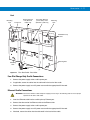
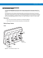
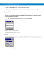
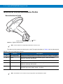
Cradle Features
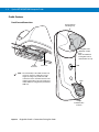
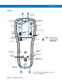
Front View and Connections
Horizontal Desk
Mounting Cup
Pairing Bar Code
(Bluetooth cradles
only)
Note: An additional
Pairing Bar Code is
affixed under the cup.
Power
Connector
NOTE
Connector
The functionality of the USB connection to
a host PC varies by cradle type. For the
single slot charge only cradle, the USB
connection can be used with a device in the
cradle for ActiveSync only. The charge only
cradle LED does not light when powered off
USB only.
LED
Latch
Charge/
Communication
Contacts
Figure 2-1 Single Slot Cradle - Connections/Pairing Bar Code
Accessories
2-5
Back View
2
Mounting
Key-Hole
1
Forklift Bracket
Screw Hole
1
Forklift Bracket
Screw Hole
Rubber Foot
Rubber
Foot
Cable Ferrite Hook
Power
Cable
Groove
Cable
Groove
Cup
Release
Snaps
Host Port
WARNING!
Power Port
Never connect an
Ethernet or phone
cable to the host
interface port.
Desk Mount
Setting
1Forklift
Bracket
Screw Hole
Rubber Foot
Wall Mount
Setting
Wall Mount
Conversion Dial
2Mounting
Key-Hole
1
Used to fasten bracket to STB2000-F (forklift) cradle.
2Used
Figure 2-2 Single Slot Cradle - Back
to mount STB20XX cradle.
2-6
Symbol MT2070/MT2090 Integrator Guide
Mounting Cups
Wall Mount Cup
Desk Mount Cup
Forklift Cup
Figure 2-3 Single Slot Cradle - Mounting Cups
Cradle Accessories
The following equipment may be needed:
For the STB2000/STB2078 cradle:
• Power supply for desk/wall mounting configuration (p/n KT-14000-148R).
• If applicable two screws, depending on the surface, for wall mounting (not available from Motorola).
For the STB2000-F cradle:
• Mounting bracket (provided).
• Power supply for forklift configuration (p/n 50-14000-122R, provided).
• Three 8-32 x 1.25 in screws to fasten the cradle to the bracket (provided).
• Four screws to fasten bracket to mounting surface (not available from Motorola).
Accessories
2-7
Supplying Power to the Cradle
The cradle receives power from one of two sources:
• An external power supply.
• When connected to the host through an interface cable that supplies power.
The cradle detects whether the host or the external supply is supplying power. It always draws power from the
external supply when available, regardless of the presence of power from a host.
Using the USB Interface to Supply Power
When the cradle is connected to the host via the USB interface, the USB port can power the cradle so that an
external power supply is not necessary. Note that powering from a USB host charges the device at a slower rate
than when charging from an external power supply.
NOTE
It is recommended to use a 12V power supply to accelerate charge times.
Connecting the STB20XX Cradle
IMPORTANT Connect the interface cable and power supply (if necessary) in the following order to ensure proper
operation of the device and cradle.
1.
Insert the host interface cable into the cradle's host port.
2.
Connect the other end of the host interface cable to the host.
3.
If necessary, connect the appropriate cable to the power supply and an AC power source (if the interface
requires, or to allow fast charging of the device).
4.
If applicable, insert the power supply cable ferrite into the support features on the cradle bottom and run the
host and power cables into their respective cable grooves.
5.
For forklift cradles only, connect the forklift power supply to the cradle's power port, if applicable. Insert the
power supply cable ferrite into the support features on the cradle bottom and run the host and power cables
into their respective cable grooves, or use cable ties to secure them to the mounting plate after attaching it to
the cradle. For more information about mounting options and procedures, refer to the documentation included
with the cradle.
6.
For Bluetooth cradles only, pair the device to the cradle by scanning the pairing bar code on the cradle.
7.
If necessary, scan the appropriate host bar code (for non-autodetected interfaces). Refer to the specific host
chapter in the MT2090/MT2070 User Guide (p/n 72E-117859-xx).
NOTE
Disconnect the power supply before changing host cables, or the device may not recognize the new host.
Different cables are required for different hosts. The connectors illustrated in each host chapter are
examples only. The connectors may be different from those illustrated, but the steps to connect the device
remain the same
2-8
Symbol MT2070/MT2090 Integrator Guide
Battery Charging in the Cradle
Single slot cradles act as power pass throughs to the device allowing the device to charge the Li-ion battery in the
device. A complete charge of a fully discharged battery can take up to four hours using external power and up to 10
hours using the interface cable.
NOTE
To charge the battery for your device, battery and charger temperatures must be between +32° F and +104° F
(0° C to +40° C).
To charge the device:
1.
Connect the single slot USB cradle to a power source.
2.
Insert the battery into the battery slot in the device noting the battery polarity.
3.
Insert the top of the device into the cradle first, then firmly press the device into place. The device’s green
charge LED indicates the device battery charging status.
4.
When charging is completed, the green LED is off and the device can be lifted out of the cradle.
NOTE
If the battery is completely discharged, and the unit is powered from a USB or RS-232 cable, it may take
up to two hours for the unit to power up.There is no indication to the user of this condition and it may
appear that the unit is not charging and/or not working correctly. However, if the unit is placed in an
STB2000 or STB2078 cradle with the 12V power supply power up is immediate.
Changing the Host Interface
To connect to a different host, or to the same host using a different cable:
1.
Disconnect the power supply from the cradle, if applicable.
2.
Disconnect the interface cable from the host.
3.
Connect the interface cable to the new host, or the new interface cable to the existing host.
4.
Reconnect the power supply, if required.
5.
If necessary, scan the appropriate host bar code (for non-autodetected interfaces). Refer to the
MT2070/MT2090 User Guide (p/n 72E-117859-xx).
CAUTION
If the device does not recognize the host, disconnect the power supply, then reconnect after
connecting the host cable.
Communication
Sending Data to the Host Computer
The STB2078-C10007WR single slot multi-interface Bluetooth cradle receives data from the device via a wireless
radio connection and transmits it to the host computer via the host cable. The device and cradle must be paired for
successful wireless communication. For detailed information about pairing, radio communications, Bluetooth
technology and lost connections to the host computer, refer to the MT2070/MT2090 Integrator Guide
(p/n 72E-117858-xx).
Accessories
2-9
LED Indicators
Table 2-2
LED Charging Status Indicators - Single Slot Charge Only Cradles
LED
Indication
LED on Device
Off
No power applied to device (battery discharged or removed); device is in low power and
ready to scan; or, battery is fully charged and device is ready to scan.
Green Flash
Device is charging (when cradle is powered from external power supply).
Red Flash
Charging problem or data transmission problem.
LED on Cradle
Off
Cradle is not powered or power fault on contacts.
Solid Blue
Cradle is powered.
Table 2-3
LED Charging Status Indicators - Single Slot Multi-interface Cradles
LED
Indication
LED on Device
Off
No power applied to device (battery discharged or removed); device is in low power and
ready to scan; or, battery is fully charged and device is ready to scan.
Green Flash
Device is charging (when cradle is powered from external power supply).
Red Flash
Charging problem or data transmission problem.
LED on Cradle
Off
Cradle is not powered.
Solid Blue
Cradle is powered.
Red/Blue/Purple
Power up sequence.
Rapid Red/Blue/Red/Blue
Power fault on all contacts.
Miscellaneous LED Indicator Information
• Single slot charge only cradle (STB2000)
• Blue LED is off when there is a USB connection but no external power supply is used.
• Single slot multi-interface Bluetooth cradle (STB2078)
• Blue LED lights when there is a USB or keyboard wedge connection but no external power supply is used.
2 - 10 Symbol MT2070/MT2090 Integrator Guide
Mounting
Horizontal (Desk) Mount
1.
The cradle is packaged with the horizontal mount desk cup installed. If it was replaced with the wall cup,
remove the wall cup and reattach the desk cup.
2.
Use a Phillips screwdriver to turn the wall mount conversion dial to the correct position for a horizontal/desktop
mount.
3.
Attach the appropriate cables.
4.
Place the cradle on the desk to and insert the device.
Vertical (Wall) Mount
Replace the desk mount cup with the wall (vertical) mount cup:
1.
Use a Phillips screwdriver to turn the wall mount conversion dial on the back of the cradle to the correct
position for a vertical (wall) mount. The front latches protract to engage the depressions at the base of the
device’s handle.
Wall Mount Setting
Desk Mount Setting
Wall Mount
Conversion Dial
Figure 2-4 Set Conversion Dial for Wall Mounting
Accessories 2 - 11
2.
Use a Phillips screwdriver to remove the screws on the back of the cradle.
Figure 2-5 Remove Back Screws
3.
Use your fingers to squeeze and hold the cup release snaps while pulling the desk cup off.
Cup release
snaps
Figure 2-6 Remove Desk Cup
2 - 12 Symbol MT2070/MT2090 Integrator Guide
4.
Use a Phillips screwdriver to remove the screws on the front of the cradle. These screws are used to secure
the wall mount cup to the cradle in Step 6.
Figure 2-7 Remove Front Screws
5.
Insert the wall mount cup into place.
Figure 2-8 Insert Wall Mount Cup
6.
Using a Phillips screwdriver and the two screws removed from the cradle in Step 4, screw the wall mount cup
to the cradle.
Figure 2-9 Screw Wall Mount Cup Into Place
Accessories 2 - 13
To mount the cradle:
1.
Attach the interface and power cables to the appropriate ports (see Figure on page 2-7).
2.
Insert the power supply cable ferrite into the support features on the cradle bottom and run the host and power
cables into their respective cable grooves.
3.
Position the cradle on the mounting surface and outline the mounting holes with a pencil, or use the mounting
template on page 2-27 to determine the location of the screw holes.
4.
Pre-drill holes to accommodate two screws.
5.
Attach the cradle key-holes to the screws and ensure the cradle hangs securely on the surface.
6.
Place the device in the cradle.
NOTE
Ensure the device does not loosen from the wall during routine usage.
Forklift Single Slot Charge Only Cradle
The mounting bracket is used to install the STB2000-F cradle on a forklift.
Attach the Mounting Bracket
1.
Use a Phillips screwdriver to turn the wall mount conversion dial on the back of the cradle to the correct
position for a vertical (wall) mount. The front latches protract to engage the depressions at the base of the
device’s handle.
Mounting Bracket
Cable Tie
Holes
Isolator
Cable
Access
Hole
Cable Tie
Holes
Isolator
Cable Tie
Holes
Forklift Mount
Conversion Dial
Figure 2-10 Attaching Forklift Mounting Bracket to Cradle
2 - 14 Symbol MT2070/MT2090 Integrator Guide
2.
Attach the applicable cables to the appropriate ports (see Connecting the STB20XX Cradle on page 2-7).
3.
Position the cradle with the screw holes in the cradle aligning with the holes in the isolators. Three isolators
ensure secure attachment with minimized vibration. The bracket has holes that provide access to the host and
power ports, and enable securing the cables with cable ties.
4.
Attach the cradle to the bracket using three 8-32 x 1.25" Phillips screws through the cradle and isolator holes.
Mounting the STB2000-F on the Forklift
1.
Consult an environmental health and safety manager to determine an appropriate mounting location within the
recommended 15" reach envelope.
Reach Envelope
15" Radius
Side View, Seated
15" Radius
Top View
15" Radius
Side View, Standing
Figure 2-11 Forklift Reach Envelope
2.
Mark the mounting surface through the four screw holes on the mounting bracket, or use the mounting
template on page 2-27 to determine the location of the screw holes.
3.
Pre-drill holes into the mounting surface to accommodate four screws.
4.
If desired, thread cable ties through the holes on each side of the bracket and secure the host and power
cables along the edges of the bracket.
5.
Attach the bracket to the mounting surface.
6.
Place the device in the cradle.
Accessories 2 - 15
Four Slot Cradles
The Symbol STB2000-C40007R four slot charge only and STB2000-C40017R four slot Ethernet cradle act as
chargers and host communication interfaces for the Symbol MT2000 Series cordless devices and batteries.
Cradles can sit on a desktop or be mounted on a wall. This document provides basic instructions for cradle set up
and use. Unless otherwise noted, cradle refers to both configurations of the cradle. Any discussion of transmission
of information refers specifically to the STB2000-C40017R four slot Ethernet cradle.
Configurations
Table 2-4 Single Slot Cradle Configurations
Cradle Configuration
Description
STB2000-C40007R
Four slot, charge only.
Charges up to four devices and up to four spare batteries.
STB2000-C40017R
Four slot, Ethernet.
Charges up to four devices and up to four spare batteries; synchronizes up to four devices
with a host computer through an Ethernet connection (see Ethernet Cradle Connections
on page 2-17).
Accessories
• Power supply (p/n 50-14000-241R) and DC cable (p/n 50-16002-029R) for desk/wall mounting configuration.
Optional:
• DC split cable (p/n 25-121355-01R); when daisy chaining, allows one power supply for two cradles.
• Four screws for wall mounting (not available from Motorola).
2 - 16 Symbol MT2070/MT2090 Integrator Guide
Cradle Features
Front
Cradle
Power LED
Device Hooks
(secure device in
the well)
Interchangeable Desk/Wall
Mount Cup (four)
Wall
Mounting
Latches
(two in each
well)
Ethernet Activity
LEDs (Ethernet
cradle only)
Device Well
(four)
Battery
Charging
LED (four)
Battery
Retention
Latch
Figure 2-12 Four Slot Cradle - Front View
Charging/
Communication
Contacts
Battery
Charging
Contacts
Battery Well (four)
Accessories 2 - 17
Back
Mounting
Hole
Power Port
Primary Ethernet
Port (Ethernet
cradle only)
Secondary Ethernet
port for daisy chain
(Ethernet cradle only)
Mounting
Hole
Wall Mount Cup
Screws
Mounting Hole
Mounting
Hole
Wall Mount
Conversion
Dial
Cable Well
(2)
Figure 2-13 Four Slot Cradle - Back View
Four Slot Charge Only Cradle Connections
1.
Connect the power supply to the cradle’s power port.
2.
If applicable, secure the cables into the cable well in the back of the cradle.
3.
Connect the power supply to an AC power source with the appropriate AC line cord.
Ethernet Cradle Connections
IMPORTANT Connect the Ethernet cable and power supply (if necessary) in the following order to ensure proper
operation of the device and cradle.
1.
Insert the Ethernet cable into the cradle’s primary Ethernet port.
2.
Connect the other end of the Ethernet cable to the Ethernet hub.
3.
Connect the power supply to the cradle’s power port.
4.
Connect the power supply to an AC power source with the appropriate AC line cord.
5.
If desired, secure the cables into the cable wells in the back of the cradle.
2 - 18 Symbol MT2070/MT2090 Integrator Guide
Daisy Chaining
When daisy chaining Ethernet cradles:
1.
Connect the power supply to the cradle’s power port.
2.
Connect the power supply to an AC power source with the appropriate AC line cord.
3.
Insert the Ethernet cable into the primary Ethernet port of the first cradle in the daisy chain.
4.
Connect the other end of the Ethernet cable to the Ethernet hub.
5.
Insert an Ethernet cable into the first cradle’s secondary port and connect the other end to the primary port of
second cradle in the chain.
6.
Insert an Ethernet cable into the second cradle’s secondary port and connect the other end to the primary port
of the third cradle in the daisy chain and continue until all cradles in the daisy chain are connected.
7.
If desired, secure all cables into the cable wells in the back of each cradle.
NOTE
Each cradle in the daisy chain requires its own power supply, or use cable p/n 25-121355-01R which is a
DC split cable allowing one power supply to be used for two cradles.
Bandwidth Considerations when Daisychaining
Each cradle added to the daisychain impacts the bandwidth allocated to each of the inserted devices, particularly
when the devices attempt to send and receive at data rates that exceed the bandwidth provided to the chain
(typically 100 Mbps). If a device in a daisychained cradle does not use its bandwidth, that bandwidth is available to
other inserted devices.
Table 2-5 shows allocated bandwidth (based on 100 Mbps) for the number of daisychained cradles, with each
device attempting transmission at the maximum data rate.
Table 2-5 Daisychaining Bandwidth
Daisychained Ethernet
Cradles
Bandwidth Allocation For Each
Ethernet Cradle (bits/sec)
Bandwidth Allocation For Each
Device (bits/sec)
Cradle 1
100,000,000
20,000,000*
Cradle 2
20,000,000
4,000,000
Cradle 3
4,000,000
800,000
Cradle 4
800,000
160,000
Cradle 5**
160,000
32,000
Cradle 6**
32,000
6,400
Cradle 7**
6,400
1,280
* The maximum bandwidth capacity for the device is 12,000,000 bits/sec.
** Depending on the application, allocated bandwidth may not be adequate.
Locating the Device IP Address
To locate the device IP address, go to the Home window on the device and select Utilities > File Explorer >
Windows > cmd.exe. Press the Enter key to run cmd.exe, type ipconfig at the command prompt and press the
Enter key.
Accessories 2 - 19
Mounting the Cradle on a Wall
The four slot cradle ships from the factory with the four wall mount cups installed. To mount the cradle on a vertical
surface:
1.
Use a Phillips screwdriver to turn the wall mount conversion dial to point to the vertical cradle/device icon.
Wall
Mount
Position
Figure 2-14 Wall Mount Conversion Dial - Wall Mount Position
2.
The wall mounting latches in the cradle protract to engage the depressions at the base of the device’s handle.
3.
Attach the interface and power cables to the appropriate ports (see the Connections sections on page 17.
4.
Secure the cables into the cable well in the back of the cradle.
5.
Position the cradle on the mounting surface, or use the template included in the User Guide.
6.
Mark the surface through the four holes on the bottom of the cradle, or use the mounting template to determine
the location of the screw holes.
7.
Pre-drill holes to accommodate four screws.
8.
Attach the cradle securely to the surface.
9.
Place the device(s) and/or batteries in the cradle.
2 - 20 Symbol MT2070/MT2090 Integrator Guide
Setting up the Cradle for Desktop Use
Remove the wall mount cups to use the four slot cradle on a desktop. Each wall mount cup is attached with two
screws on the back of the cradle.
To mount the cradle on a horizontal surface:
1.
Use a Phillips screwdriver to remove the two screws on the back of the cradle attaching each wall mount cup.
Figure 2-15 Remove Screws
2.
Pull each wall mount cup out of the device well.
Figure 2-16 Remove Wall Mount Cup
Accessories 2 - 21
3.
Use a Phillips screwdriver to turn the wall mount conversion dial to point to the horizontal cradle/device icon.
Desk Mount
Position
Figure 2-17 Wall Mount Conversion Dial - Desk Mount Position
4.
The wall mounting latches in the cradle truncate.
5.
Attach the interface and power cables to the appropriate ports (see the Connections sections on page 17.
6.
Secure the cables into the cable well in the back of the cradle.
7.
Place the cradle on a flat surface.
Optional: The cradle can be attached securely to the surface using the wall mounting holes. See Mounting the
Cradle on a Wall on page 2-19 for details.
8.
Place the device(s) and/or batteries in the cradle.
Inserting Devices and Batteries in the Cradle
When inserting the device in the cradle, insert the device top first. Push the handle until it clicks into place,
engaging the contacts in the cradle and device.
When inserting batteries in the cradle, align the connectors on the bottom of the battery with the battery charging
connectors in the cradle. Push down on the top of the battery until it clicks into place, engaging the contacts in the
cradle.
Desk Mount
Wall Mount
2
1
1
2
1
2
Figure 2-18 Inserting Devices
NOTE
When inserting the device in a wall mounted cradle, ensure the device’s hook recesses engage the hooks
on the wall mount adapter.
2 - 22 Symbol MT2070/MT2090 Integrator Guide
Sending Data to the Host Computer
MT2000 Series include Ethernet cradle drivers that initiate automatically when you place the device in a properly
connected four slot Ethernet cradle. The cradle receives data from the device and transmits it to the host computer
via the Ethernet cable.
Prior to inserting the device in the cradle, it is recommended that you turn off the device’s wi-fi radio to avoid
interference. To turn off the radio, go to the Home window on the device and select Config > Wireless Companion
> Disable Radio.
Charging
To charge the battery in the device and/or a spare battery, ensure the correct power supply is connected then place
the device/battery in the cradle (see Inserting Batteries). Charging begins when the LED indicators, on the device
and in the cradle’s spare battery section, start flashing green. A complete charge of a fully discharged battery can
take up to four hours.
LED Indicators
Table 2-6 LED Charging Status Indicators - Device LEDs
LED Indicators
Off
No power applied to device (battery discharged or removed); device is in low power and ready to
scan; or, battery is fully charged and device is ready to scan.
Green Flash
Device is charging.
Red Flash
Charging problem or data transmission problem.
Table 2-7 LED Charging Status Indicators - Cradle LEDs
LED Indicators
Solid Blue (Cradle
Power LED)
Cradle is powered.
Ethernet Activity
LEDs (Ethernet
cradles only)
Speed LED (100/10) - Primary Port Connection
The cradle’s green Speed LED lights to indicate that the transfer rate is 100 Mbps. When it is not lit
it indicates that the transfer rate is 10Mbps.
Link LED (
) - Primary Port Connection
The cradle’s amber Link LED blinks to indicate activity, or stays lit to indicate that a link is
established. When it is not lit it indicates there is no link.
Accessories 2 - 23
Four Slot Battery Charger
The Symbol SAC2000-4000CR four slot spare battery charger charges up to four single spare batteries. The
cradle can sit on a desktop or be mounted on a wall. This document provides basic instructions for cradle set up
and use.
For best performance, fully charge the device battery before using the device for the first time. To charge the
device battery, insert the battery in the cradle. The battery begins charging when the LED indicator on the battery
charger starts flashing green. A complete charge of a fully discharged battery can take up to four hours. Charge
within the recommended temperature of 32° to 104° F (0° C to 40° C) nominal, 41° to 95° F (5° to 35° C) ideal.
Accessories
• Four screws (for wall mounting, if applicable, not available from Motorola).
• Power supply for desk/wall mounting configuration (p/n 50-14000-148R).
Battery Charger Features
Front
Battery
Well (4)
Battery
Charging
Connectors (4)
Blue Power
LED
Green Charging
LED Indicator (4)
Figure 2-19 Four Slot Battery Charger - Front
2 - 24 Symbol MT2070/MT2090 Integrator Guide
Back
Rubber Foot (4)
Power Cable
Groove
Wall Mount Screw
Supports (4)
Power Cable Power Port
Ferrite Well
Figure 2-20 Four Slot Battery Charger - Back
Mounting
To mount the cradle on a vertical (wall) surface:
1.
Connect the power cable to the power port and an AC power source.
2.
Insert the power supply cable ferrite into the power cable ferrite well on the bottom of the cradle; run the power
cable into the cable groove.
3.
Use the mounting template beginning on page 2-26 to determine the location of the screw holes.
4.
Pre-drill holes to accommodate four screws.
5.
Attach the cradle securely to the surface.
6.
Insert up to four batteries to charge.
Accessories 2 - 25
Inserting Batteries
To insert batteries in the cradle, align the connectors on the bottom of the battery with the battery charging
connectors in the cradle. Push down on the top of the battery until it clicks into place, engaging the contacts in the
cradle.
Figure 2-21 Inserting Batteries
Charging Batteries
The battery begins charging when the green LED indicator flashes. A complete charge of a fully discharged battery
can take up to four hours using external power.
LED Indicators
Table 2-8
LED Charging Status Indicators - Four Slot Battery Charger LEDs
LED
Indication
Flashing Green Battery LED
Flashes when battery charges.
Solid Green Battery LED
Battery is fully charged.
Solid Blue Cradle LED
Lights when power is applied; off when there is no power applied.
Fast Green Flash
Error condition.
2 - 26 Symbol MT2070/MT2090 Integrator Guide
Troubleshooting
For detailed cradle and battery charger information see Chapter 9, Maintenance and Troubleshooting.
Wall Mount Templates
Wall mount templates for the single slot cradle and forklift cradle begin on page 2-27.
The four slot cradle template is located on the Web at: http://www.motorola.com/enterprisemobility/manuals.
Accessories 2 - 27
7.84 in
(199.0 mm)
Single Slot Cradle Mounting Template
2 - 28 Symbol MT2070/MT2090 Integrator Guide
Four Slot Battery Charger Mounting Template
3.29 in
(83.5 mm)
5.35 in
(136.0 mm)
Chapter 3 ActiveSync
Introduction
To communicate with the host computer, install Microsoft ActiveSync (version 4.0 or higher) on the host computer.
Changes made on the device or host computer appear in both places after synchronization.
ActiveSync software:
• Allows working with device-compatible host applications on the host computer. ActiveSync replicates data
from the device so the host application can view, enter, and modify data on the device.
• Synchronizes files between the device and host computer, converting the files to the correct format.
• Backs up the data stored on the device. Synchronization is a one-step procedure that ensures the data is
always safe and up-to-date.
• Copies (rather than synchronizes) files between the device and host computer.
• Controls when synchronization occurs by selecting a synchronization mode, e.g., set to synchronize
continually while the device is connected to the host computer, or set to only synchronize on command.
• Selects the types of information to synchronize and control how much data is synchronized.
Setup
The device communicates with a host PC via ActiveSync in an STB 2000 cradle with a USB cable connection, or
with a direct USB cable connection from device to host PC. Chapter 2, Accessories provides information about
setting up the device/cradle to communicate.
NOTE
The STB2078 cradle does not support ActiveSync.
3-2
Symbol MT2070/MT2090 Integrator Guide
Installing ActiveSync
To install ActiveSync on the host computer, download the latest version of the software from the Microsoft Web site
at http://www.microsoft.com. Refer to the installation and RAS instructions included with the ActiveSync software.
NOTE
Microsoft recommends installing ActiveSync on the host computer before connecting the device.
ActiveSync is automatically enabled when the device is placed in the STB2000 cradle with a USB cable
connection. Alternatively, ActiveSync can be enabled through the on-board RJ45 jack on the device. This requires
device configuration on the Configure USB window. On the device Home window, select Configure USB >
ActiveSync. Refer to Chapter 2, Operating in the MT2070/MT2090 User Guide (p/n 72E-117859-xx) for detailed
information about configuring the device.
Setting Up an ActiveSync Connection on the Host Computer
1.
If not already installed, install Microsoft ActiveSync on the host computer.
2.
Select Start > Programs > Microsoft ActiveSync on the host computer. The ActiveSync window displays.
NOTE
If the device is connected to the host computer prior to running ActiveSync, a Guest connection occurs
automatically. If the device is not connected to the host computer prior to running ActiveSync, a Guest
connection occurs as soon as the device connects.
Figure 3-1 ActiveSync Window
NOTE
Assign each device a unique device name. Do not try to synchronize more than one device to the same name.
ActiveSync
3.
3-3
In the ActiveSync window, select File > Connection Settings. The Connection Settings window displays.
Figure 3-2 Connection Settings Window
4.
Select the appropriate check box for the type of connection used.
5.
Select the Show status icon in taskbar check box.
6.
Select the Open ActiveSync when my device connects check box.
7.
Select Automatic in the This computer is connected to: drop-down list.
8.
Click OK to save any changes made.
No partnership is necessary to synchronize information between the device and host computer.
For more information about using ActiveSync, start ActiveSync on the host computer, then see ActiveSync Help.
3-4
Symbol MT2070/MT2090 Integrator Guide
Chapter 4 Software Installation on
Development PC
Introduction
To develop applications to run on the device, use one or all of the following:
• Enterprise Mobility Developer Kit (EMDK) for C for both WinCE 4.2 and Win CE 5.0
• Windows CE Platform SDK for MT2070/MT2090 or Windows CE 5.0 standard SDK
• Device Configuration Package (DCP) for MT2070/MT2090
• MCL Collection, p/n SWE-123872-01, includes MCL Designer and MCL Link. Refer to Solution Builder for
additional MCL part numbers.
The EMDK is a development tool used to create native C applications for devices. It includes documentation,
header files (.H), and library files (.LIB) for native code application development that targets Motorola value-add
APIs.
The Windows CE Platform SDK for the MT2070/MT2090 is used in conjunction with the EMDK for eVC4 to create
Windows CE applications for the MT2070/MT2090 device. The Platform SDK installs a new Windows CE device
type and its associated libraries onto the development PC. This new device is added to the Active WCE
Configuration field of Microsoft eMbedded Visual C++ 4.0 (eVC4). You may also use the standard CE 5.0 SDK
from Microsoft.
The Device Configuration Package (DCP) is required to create and download hex images that represent flash
partitions to the device. The DCP includes the user documentation, flash partitions, Terminal Configuration
Manager (TCM) and the associated TCM scripts, and Symbol Configuration Manager (SCM).
4-2
Symbol MT2070/MT2090 Integrator Guide
Required System Configurations
The minimum system configuration required to use the EMDK for MT2070/MT2090 is:
• IBM-compatible host computer with Pentium 450 MHz processor or higher
• Microsoft Windows XP or Microsoft Windows 2000 operating system
• 128 MB RAM
• 100 MB available hard disk space
• CD-ROM drive
• One available serial port
• Mouse
• Adobe® Acrobat® Reader® 3.0 or higher, available at the Microsoft Web site: http://www.microsoft.com
• Microsoft ActiveSync version 3.7 or higher, available at the Microsoft Web site: http://www.microsoft.com
• Microsoft Embedded Visual C++ v4.0 with SP2
• Microsoft Windows Mobile 2003 SDK.
DCP for MT2070/MT2090
Installing
To install the DCP for MT2070/MT2090:
1.
Download the EMDK from the Support Central Web site at:
http://www.motorola.com/enterprisemobility/support.
a.
Select Software Downloads from the menu list on the left side of the page.
b.
Select Bar Code Scanners.
c.
Select MT2070/MT2090.
d.
On the MT2070/MT2090 product page, select the Device Configuration Package (DCP) for
MT2070/MT2090 from the Software Downloads section.
e.
Save the .exe file to the development computer.
2.
Locate the .exe file on the development computer, double-click the file, and follow the install prompts.
3.
Once installed, access the major components of the DCP from the Device Configuration Package (DCP) for
MT2070/MT2090 program group.
Software Installation on Development PC
Components
Table 4-1 lists the components of the MT2070/MT2090 DCP.
Table 4-1 DCP for MT2070/MT2090 Components and Locations
Component
Description
Directory Location
Files that make
up the flash
partitions
Used to configure the device.
\Program Files\Motorola Device Configuration
Packages\MT209070c50Aen\v1.0\Flash Folders
Hex image default location
Loads onto the device for
configuration.
\Program Files\Motorola Device Configuration
Packages\MT209070c50Aen\v1.0\Hex Images
User
Documentation
User manuals that provide guidance
on using and integrating the
MT2070/MT2090.
\Program Files\Motorola Device Configuration
Packages\MT209070c50Aen\v1.0
Readme
Contains important information for
the DCP.
\Program Files\Motorola Device Configuration
Packages\MT209070c50Aen\v1.0
Operating
System Update
Contains the OSUPDATE Package
Builder and Images.
\Program Files\Motorola Device Configuration
Packages\MT209070c50Aen\v1.0\OSUpdate
Scripts
Used to customize flash partitions.
\Program Files\Motorola Device Configuration
Packages\MT209070c50Aen\v1.0\TCM Scripts
Tools (e.g.,
Keyboard
remap, if any)
Used in developing applications for
the device.
\Program Files\Motorola Device Configuration
Packages\MT209070c50Aen\v1.0\Tools\kbtool
4-3
4-4
Symbol MT2070/MT2090 Integrator Guide
Platform SDK
To download and install the MT2070/MT2090 Platform SDK:
1.
2.
Download the appropriate Platform SDK from the Support Central Web site at:
http://www.motorola.com/enterprisemobility/support.
a.
Select Software Downloads from the menu list on the left side of the page.
b.
Select Bar Code Scanners.
c.
Select MT2070/MT2090.
d.
On the MT2070/MT2090 product page, select the appropriate Platform SDK for MT2070/MT2090 from the
Software Downloads section.
e.
Save the .exe file to the development computer.
Locate the .exe file on the development computer, double-click the file, and follow the install prompts.
Software Installation on Development PC
4-5
Enterprise Mobility Developer Kit
To install the EMDK:
1.
Download the EMDK from the Support Central Web site at:
http://www.motorola.com/enterprisemobility/support.
a.
Select Software Downloads from the menu list on the left side of the page.
b.
Select Bar Code Scanners.
c.
Select MT2070/MT2090.
d.
On the MT2070/MT2090 product page, select the appropriate Enterprise Mobility Developer Kit for C from
the Software Downloads section.
e.
Save the .exe file to the development computer.
2.
Locate the executable, double-click the executable file, and follow the installation prompts.
3.
Once installed, access the major components of the EMDK from the Enterprise Mobility Developer Kit program
group of the Windows Start menu. The components include: Help, Platform Integrator, Readme, Samples, and
Web Updates.
Download updates to the EMDK from the URL above. Check this site periodically for important updates and new
software versions.
Installing Other Development Software
Developing applications for the device may require installing other development software such as application
development environments on the development PC. Follow the installation instructions provided with this software.
4-6
Symbol MT2070/MT2090 Integrator Guide
Chapter 5 Software Installation on the
MT20X0
Introduction
With the appropriate accessory, software and connection, the device can share information with the host device.
This chapter provides information about installing software and files on the device.
To download and install software use:
• ActiveSync
• IPL.
ActiveSync
Use ActiveSync to copy files from a host computer to the device.
1.
Install ActiveSync on the development PC. See Chapter 3, ActiveSync for more information.
2.
Connect the device to the host computer using a USB cradle or an appropriate cable. See Chapter 2,
Accessories for connection information.
3.
On the host computer, select Start > Programs > ActiveSync.
Figure 5-1 ActiveSync Connected Window
5-2
Symbol MT2070/MT2090 Integrator Guide
4.
Select Explore.
Figure 5-2 ActiveSync Explorer
5.
Double-click a folder to expand the contents of the folder.
Figure 5-3 Application Folder Contents
6.
Use Explorer to locate the host computer directory that contains the file to download. Click that directory in the
left pane to display its contents in the right pane.
7.
Drag the desired file(s) from the host computer to the desired mobile device folder.
• Program Files folder: files stored in this folder are discarded after a cold boot.
• Application folder: files stored in this folder are retained after a cold boot.
Software Installation on the MT20X0
5-3
Updating the Operating System
Using IPL
See Chapter 6, Creating/Loading Hex Images to update the OS via TCM.
Using ActiveSync
1.
Install the DCP onto the desktop computer.
2.
Connect the MT20X0 to the desktop computer.
a.
Connect the desktop computer to the MT20X0 via a USB cable and an STB2000 cradle.
or
3.
4.
b.
Connect the desktop computer directly to the MT20X0 via a USB cable.
c.
On the device’s Home screen, select Config… > Configure USB > ActiveSync.
On the drive in which you installed the DCP, execute the following batch file:
a.
MT2070: ActiveSyncOSupdateMT2070.bat
b.
MT2090: ActiveSyncOSUpdateMT2090.bat
The operation should complete in approximately 20 minutes. If the operation fails to complete, remove excess
files from the application partition, cold boot the device and retry the update.
Using Airbeam
See AirBEAM Smart Client on page 8-17.
5-4
Symbol MT2070/MT2090 Integrator Guide
Adding Programs
Install the appropriate software on the host computer before installing it on the device:
1.
Download the program to the host computer (or insert the CD or disk that contains the program into the host
computer). The program may consist of a single *.exe file, a *.zip file, or a Setup.exe file.
2.
Read any installation instructions, Read Me files, or documentation that comes with the program. Many
programs provide special installation instructions.
3.
Connect the device to the host computer.
4.
Double-click the executable file on the host computer.
If the file is an installer, the installation wizard begins. Follow the directions on the window. Once the software is
installed on the host computer, the installer transfers the software to the device.
If the file is not an installer, an error message states that the program is valid but is designed for a different type
of computer. Move this file to the device. Follow the installation instructions for the program in the Read Me file
or documentation, or use ActiveSync Explore to copy the program file to the Program Files folder on the device
as described in ActiveSync on page 5-1. For more information on copying files using ActiveSync, see
ActiveSync Help.
5.
When installation is complete, go to Home > Utilities > File Explorer to find and launch the new program.
IPL
See Chapter 6, Creating/Loading Hex Images to download customized flash file system partitions to the device and
load hex files to the flash memory of the device using IPL.
Chapter 6 Creating/Loading Hex Images
Introduction
Terminal Configuration Manager (TCM) is an application used to customize flash file system partitions for the
device. The most common use is to create an application partition hex file that contains the customer's application.
TCM can also be used to load hex files to the flash memory of the device.
The program resident on the device that receives the hex file and burns it to the flash memory is called Initial
Program Loader (IPL).
TCM scripts control the customization of partitions. The scripts contain all of the necessary information for building
an image. The script is a list of copy commands specifying the files to copy from the development computer to the
partition.
TCM works with a pair of directory windows, one displaying the script and the other displaying the source files
resident on the development computer. Use standard drag and drop operations to add and delete from the script
window.
The DCP includes scripts used by Motorola to build the standard factory installed Platform and Application
partitions provided on the device. The standard Platform partition contains drivers while the Application partition
contains demo applications and optional components. The standard TCM scripts can be found in the following
folder: C:\Program Files\Symbol Windows CE EMDK (MT2070/MT2090)\SymbolPlatforms
\MT2070/MT2090\TCMScripts.
NOTE
Before creating a script to build a hex image, identify the files required (system files, drivers, applications,
etc.) and locate the files’ source directories to make the script building process easier.
The required processes for building a hex image in TCM include:
• Starting TCM
• Defining script properties
• Creating the script for the hex image
• Building the image
• Sending the hex image
• Creating a splash screen
• Flash storage.
6-2
Symbol MT2070/MT2090 Integrator Guide
Starting Terminal Configuration Manager
NOTE
Screens and windows pictured are samples and can differ from actual screens.
Click the Windows start menu > TCM icon to start TCM. The TCM window appears displaying two child windows:
Script1 and File Explorer. The Script1 window contains a newly created script and the File Explorer window
contains a file explorer view used for selecting files to place in the script.
Figure 6-1 TCM Startup Window
The following table lists the components of the TCM window.
Table 6-1 TCM Components
Icon
Component
Function
Script window
Displays the files to use in the creation of the partition(s).
File Explorer window
Used to select the files to add to the script.
Create button
Create a new script file.
Open button
Open an existing script file.
Creating/Loading Hex Images
6-3
Table 6-1 TCM Components (Continued)
Icon
Component
Function
Save button
Save the current script file.
Large icons button
View the current script items as large icon.
Small icons button
View the current script items as small icon.
List button
View the current script items as a list.
Details button
View the current script items with more details.
About button
Display version information for TCM.
Properties button
View/change the current script properties.
Build button
Build the current script into a set of hex files.
Check button
Check the script for errors (files not found).
Send button
Download the hex image to the device.
Tile button
Arrange the sub-windows in a tiled orientation.
Build and Send
Build the current script into a set of hex images and send the hex
images to the device.
Preferences button
View/change the global TCM options.
6-4
Symbol MT2070/MT2090 Integrator Guide
Defining Script Properties
Define script properties before creating a script This defines the type of device, flash type, number of disks being
created, and the memory configuration of each disk partition.
NOTE
The windows displayed in the following steps are examples only. The data displayed in the window fields
do not reflect the actual data for the MT2070/MT2090 devices.
To define the script properties:
1.
Select the Script window to make it active.
2.
Click the Properties button. The Script Properties window > Partition Data tab displays.
Figure 6-2 Script Properties Window - Partition Data Tab
3.
In the Terminal drop-down list, ensure the MT2070/MT2090w v1.0 64M entry is selected.
4.
Use the default Flash Type.
5.
In the Disks drop-down list, select the number of disk partitions to create.
6.
Select the (memory) Size for each partition. Note that adding space to one disk partition subtracts it from
another.
7.
In the Access drop-down list for each disk partition, determine and select the Read/Write access option.
8.
Click the Options tab.
Figure 6-3 Script Properties Window - Options Tab
9.
Set the paths for the Script File, Flash File, and Hex File Build.
10. Click OK.
Creating/Loading Hex Images
6-5
Creating the Script for the Hex Image
On start-up, TCM displays the TCM window with the Script1 window and File Explorer window pointing to the
following directory:
\Program Files\Symbol Device Configuration Packages\MT2070/MT2090w\v0.1\TCMScripts\
The Script1 window directory pane displays two partitions: Platform and Application. Depending on the type of flash
chip, the number of partitions may change. Files can be added to each of the partitions. TCM functionality includes:
• Opening a new or existing script file
• Copying components to the script window
• Saving the script file.
Opening a New or Existing Script
A script file can be created from scratch or based on an existing script file. Click Create to create a new script or
click Open to open an existing script (for example, a script provided in the MT2070/MT2090 DCP. If changes are
made to an existing script saving the changes overwrites the original script. To avoid this use the Save As function
to save the script using a different file name.
Updating TCM 1.X Scripts
To upgrade script files created with older versions of TCM to TCM 2.0 scripts click Open to open the existing script.
The Conversion window displays.
Figure 6-4 Conversion Window - Upgrading to TCM 2.0
In the Select a Version field, select a version and then click OK.
Copying Components to the Script
Script contents are managed using standard file operations such as New Folder, Delete, and Rename. To add
items to the script files and folders in the File Explorer window and drag them to the Script window. The File
Explorer window supports standard windows; to select multiple files click while holding the SHIFT or CTRL keys.
Saving the Script
To save modifications to a script file use the Save or the Save As function. Saving changes to an existing script
over writes the original script. To use a Motorola-supplied standard script as a base and save the changes in a new
script, use the Save As function.
6-6
Symbol MT2070/MT2090 Integrator Guide
Building the Image
After creating the script, build the hex image defined by the script.
As part of the build, TCM performs a check on the script which verifies that all files referenced in the script exist.
This check is important for previously created scripts to ensure that files referenced in the script are still in the
designated locations.
To build scripts:
1.
Click Build on the TCM toolbar. The Configure Build window displays.
Figure 6-5 Configure Build Window
2.
Select the items (partitions) to build using the check box(es) to the left of each named partition.
3.
Specify the Build Path to define where to store all built partitions.
4.
Select the hex image check box to reduce the size and speed up the download.
5.
Click OK and follow the on-screen instructions.
If building the splash screen partitions, a prompt appears requesting both the source bitmap file and the
destination hex file.
6.
TCM perform a check and if there are no errors, creates the partition hex files.
If the build fails, TCM does not create the hex files and displays an error message. Two of the most common
reasons for a build failure are:
• Files defined in the script can not be found. This error can occur when the files referenced by the script are
no longer stored on the development computer or the folders where they are stored were renamed.
• The total amount of flash memory space required by the script exceeds the image size. To correct this,
reduce the number of files in the partition or increase the size of the partition. See Defining Script Properties
on page 6-4 for more information about setting the image size appropriately.
Creating/Loading Hex Images
6-7
Downloading the Hex Image
Once the hex file is built, download it to the device.
Using a USB Connection
To load the hex files on to the device:
1.
For downloads using a USB connection, connect the device to the development computer using the single slot
USB cradle.
CAUTION
Ensure that power is applied to the device. To ensure a successful download, do not remove power
from the device while in IPL mode.
2.
Press and hold the yellow Scan trigger and the 2 key simultaneously until the device cold boots.
3.
Release the yellow Scan trigger and the 2 key and press and hold the ENT (Enter) key until the device resets
into IPL.
4.
When the Initial Program Loader menu appears, release the ENT (Enter) key.
Initial Program Loader
Platform
Application
Windows CE
Monitor
Splash Screen
Power Micro
Partition Table
Command File
System Reset
Auto Select
Figure 6-6 Initial Program Loader Menu
5.
Choose Auto Select or use the up and down scroll buttons to select the partition to download, then press ENT.
Table 6-2 IPL Menu Partitions
Partition
Name
Description
Platform
Contains the files in the Platform folder.
Application
Contains the files in the Application folder.
Config Block
Contains information to correctly configure the operating system for the device. This information
is loaded by the manufacturer.
Note: Ensure that a correct config block is loaded in the device. Loading an incorrect config block
prevents the correct operation of the device.
Windows CE
Contains the operating system for the device.
6-8
Symbol MT2070/MT2090 Integrator Guide
Table 6-2 IPL Menu Partitions (Continued)
Partition
Name
Description
Monitor
Contains the Monitor and IPL programs.
Splash Screen
Contains the splash screen that displays while booting the device.
Note: Splash screens are generated from .bmp images. See Splash Screen Format on page
6-14. For mono displays, the bmp image must be 8 bits per pixel (bpp).
Power Micro
The Power Micro is a small computer contained within the device that controls several system
resources. In the unlikely event that the Power Micro firmware needs updating, select this item to
program the device.
Partition Table
Contains the partition information for all other partitions.
Note: The partition table should never need changing unless the sizes of the platform and
application images are changed within TCM. If this is done, load the new partition table first,
followed by both platform and application in any order.
Command File
Displays the Select Transport menu.
System Reset
Exits IPL and cold boots the operating system.
Auto Select
Allows downloading one or more files without manually selecting the destination. (The content of
the downloaded files directs the file to the correct destination.) For technical reasons, Auto Select
can not be used to download Monitor, Power Micro, or Partition Table. These items must be
specifically selected.
NOTE
6.
If the platform or application partition size changes, download a new partition table first.
IPL displays the Select Transport menu which lists the available methods of downloading the file.
Select Transport
USB
SD/MMC
ActiveSync Uart - Serial
Previous
Top
Figure 6-7 Select Transport Menu
Creating/Loading Hex Images
7.
6-9
Use the up and down scroll keys to select the USB transport method, then press ENT. The Select Transport
menu, the Waiting for Download message displays.
Downloading . . . .
Auto Select
via USB standard
waiting for input . . . .
Figure 6-8 Waiting for Download
8.
On the development computer, click Load on the TCM toolbar. The Load Terminal window - Serial tab displays.
Figure 6-9 Load Terminal Window - Serial Tab
9.
Select the Image Files To Load.
10. Select USB: Symbol Device from the Comm Port drop-down list.
NOTE
The USB: Symbol Device option does not appear on the Comm Port drop-down list until after the Waiting
for Download message completes.
11. Click Download to begin the download process. The Downloading screen on device displays the Device
Status and a progress bar.
12. When complete, Device Status displays Result was: Success!, or in the case of an error, the cause of the error.
Downloading:
“Partition Name”
via “Device Parameters”
Result was: Success!
Press any key to continue
Figure 6-10 Downloading Complete Screen
13. Press ENT to return to the IPL menu to select the next partition to download.
14. To exit IPL, select the System Reset item from the IPL menu.
6 - 10 Symbol MT2070/MT2090 Integrator Guide
TCM Error Messages
TCM validates the cells in the partition table when the Execute button is clicked. Cells highlighted in red contain an
error. Partition loading is disabled until all errors are corrected.
Table 6-3 TCM Error Messages
Error
Description/Solution
Failed to build images: flash file
system DLL not loaded!
TCM could not load the DLL required to build images for the targeting flash file
system. Reinstall TCM or recover the DLL.
Failure finding directory xxx
Building process failed because directory xxx was not found.
Failure creating volume
Building process failed because TCM could not create a certain disk volume.
Failure adding system file to image
Build process failed because TCM failed to add a certain system file to the
disk image.
INVALID PATH
The path for the image file to build is not valid.
Nothing Selected To Build
In the Config Build window, no item is selected to build.
Illegal ESS ID
In the Build ESSID Partition window, no ESS ID was entered or the ESS ID
entered was illegal.
Disk Full
TCM failed to create Hex image file at the selected path. Check available disk
space.
Target Disk Full
Build process failed because TCM failed to add file to the image of a disk
volume. Remove some files or increase the disk size.
Hex file is READ ONLY
The Hex image file to be created exists and is read-only. Delete the existing
file or change its attribute.
Error opening the file xxx with write
access
TCM could not open file xxx with write access. Check if file is in use.
Failure creating binary file
TCM failed to open/create an intermediate binary file.
Hex File To load is missing or
invalid
In Load Terminal window, the file selected to load has invalid status.
Could not locate terminal name in
TCM.ini file
While loading the Script Properties window, TCM could not find the TCM.ini
section corresponding to the device type specified by the current opening
script. Either TCM.ini or the script file is invalid.
Incorrect disk sizes in TCM.ini file
The total disk size specified in the script does not match the total disk size
defined in the corresponding TCM.ini section. Check if the script is corrupt or
the TCM.ini has changed after the script was created.
INVALID DIRECTORY
In Script Properties window, the selected System File Path is not a valid
directory.
One of the disk sizes is one sector
in size
In Script Properties window, one of the disks is too small (one sector in size).
This may cause problem while building images, especially when cushion is
enabled. Increase the disk size.
Creating/Loading Hex Images 6 - 11
Table 6-3 TCM Error Messages (Continued)
Error
Description/Solution
INVALID VOLUME NAME
In Script Properties window, one of the volume labels is not valid.
Corrupt TCM.INI file! (Invalid value
of VolumeDivisor)
The VolumeDivisor entry is missing or invalid in the TCM.ini. Reinstall TCM or
recover TCM.ini.
Invalid version of TCM script file
The TCM script was not created by this version of TCM.
Corrupt or missing TCM.ini file
TCM could not find TCM.ini file.
FAILED CONNECTION TO COM
PORT (Could not get status)
While downloading images to device, TCM failed to connect to the selected
COM port. Check if the COM port is free and is properly configured.
FAILED CONNECTION TO
TERMINAL (Terminal Not
Connected Properly/Terminal Not
Ready to Receive)
While downloading images, TCM failed to connect to the device. Check if the
correct flow control protocol is selected and the device is properly connected
and is in a listening state.
IPL Error Detection
While receiving data, IPL performs many checks on the data to ensure that the data is received correctly. If an error
is detected, IPL immediately aborts the download, and reports the error on an error screen.
Error screens vary depending on the action performed. A sample error screen may look like the screen pictured
below:
Downloading:
Platform
via Serial Port 115200
Error # -2 : Messages:
Cancelled by user
Press any key to continue
Figure 6-11 IPL Error Screen
This error message screen displays until a key is pressed. Once the screen is acknowledged, IPL returns to the
Initial Program Loader main menu to wait for a new selection.
To find the probable cause of the error, use the error number and/or the error text displayed on the screen to look
up the error in Table 6-4.
6 - 12 Symbol MT2070/MT2090 Integrator Guide
Table 6-4 IPL Errors
Error
Number
Error Text
Probable Cause
Unknown error
-1
A general error occurred. Retry the download. If the failure persists, it is
most likely due to a hardware failure; the device requires servicing.
Cancelled by user
-2
The user cancelled the download.
Can't open the source
-7
An error occurred opening the source device (either radio card or serial
port). Check source device connectivity and retry.
Can't open the
destination
-8
An error occurred opening the destination device (either flash ROM or
Power Micro). Retry the download. If the failure persists, it is most likely
due to a hardware failure; the device requires servicing.
Can't read from the
source device
-9
The source device (either radio card or serial port) could not be read from.
Check source device connectivity and retry.
Can't write to the
destination device
-10
The destination device (either flash ROM or Power Micro) could not be
written to. Retry the download. If the failure persists, it is most likely due to
a hardware failure; the device requires servicing.
Transmission
checksum error
-11
An error occurred during transmission from the source device (either
radio card or serial port) and the checksum check failed. Check source
device connectivity and retry.
Readback checksum
error
-12
A checksum, generated from reading back data that was written to the
destination device, was incorrect. An error during transmission or a write
error to the destination device could cause this.
There is no more heap
space available
-14
There is no more heap space available for the download procedure.
Restart IPL and retry the download. If the failure persists, contact service
with details of what is being downloaded.
Insufficient data
available to complete
record
-21
A Symbol hex file download was attempted but the hex file is invalid.
Ensure the file is in Symbol hex file format.
Invalid Symbol HEX file
-23
A Symbol hex file download was attempted but the hex file is invalid.
Ensure the file is in Symbol hex file format.
Unrecognized or
unsupported HEX
record
-24
The Symbol hex file being downloaded contains an invalid or
unrecognized hex record. Ensure the file is in proper Symbol hex file
format.
Invalid data in HEX file
-25
The Symbol hex file being downloaded contains invalid data. Ensure the
file is in proper Symbol hex file format with valid hex data.
Exceeded max size
-26
The download file is too large to fit into the space allocated for it. Either
make the file smaller or increase the space allocated for it by altering the
partition table.
Partition is not valid on
this device
-27
The downloaded file specifies a partition entry that does not exist on the
device. Only download files that are valid for this device, or change the
partition table so that the new file is valid on the device.
Creating/Loading Hex Images 6 - 13
Table 6-4 IPL Errors (Continued)
Error Text
Error
Number
Probable Cause
Wrong destination code
-28
A specific partition was chosen from the Main Menu (not Auto Select) but
the file selected for download was for another partition. Ensure that the
partition selected from the Main Menu matches the file selected for
download.
File type does not
support IPL Auto Select
-29
Monitor, Power Micro and Partition Table cannot be loaded with Auto
Select. Select the appropriate area, and try again.
Non-contiguous record
found
-30
A Symbol hex file download was attempted but the hex file is invalid.
Ensure the file is in Symbol hex file format.
Timed Out - No data
-31
IPL was waiting for data from the source device but timed out before
receiving any. Check the source device connectivity and retry.
Fail: Buffer Overrun
-32
The serial port device could not keep up with incoming data. Retry the
serial download with a lower baud rate.
Partition Table not Valid
-33
The size of flash memory is different than that described in the partition
table. Retry the download with the correct partition table file.
Invalid file format
-34
The file format is invalid. IPL only supports Symbol hex files.
6 - 14 Symbol MT2070/MT2090 Integrator Guide
Creating a Splash Screen
The MT2070/MT2090 DCP includes source bitmap files used to create the default splash screens for the device.
Modify these files using any of the standard windows image editors to allow customization.
To create a custom splash screen:
1.
Use the image editor to open the Splashmono.bmp file supplied with the Series 1000 DCP.
2.
Modify the bitmap file and save.
3.
Create a splash partition using the steps shown in Building the Image on page 6-6.
Splash Screen Format
If the default files are not used to create the new splash screens, be sure to preserve the image format. The
formats are as follows:
Table 6-5 Splash Screen Format
Screen Type
Monochrome
Dimensions
216 x 240
Color Format
8 bits per pixel
See Downloading the Hex Image on page 6-7 for information about loading the splash screen using TCM and IPL.
Flash Storage
In addition to the RAM-based storage standard on Windows CE devices, the device is also equipped with a
non-volatile Flash-based storage area which can store data (partitions) that can not be corrupted by a cold boot.
This Flash area is divided into two categories: Flash File System (FFS) Partitions and Non-FFS Partitions.
FFS Partitions
The device includes two FFS partitions. These partitions appear to the device as a hard drive that the OS file
system can write files to and read files from. Data is retained even if power is removed.
The two FFS partitions appear as two separate folders in the Windows CE file system and are as follows:
• Platform: The Platform FFS partition contains Motorola-supplied programs and Dynamic Link Libraries
(DLLs). This FFS is configured to include DLLs that control system operation. Since these drivers are
required for basic device operation, only experienced users should modify the content of this partition.
• Application: The Application FFS partition is used to store application programs needed to operate the
device.
Creating/Loading Hex Images 6 - 15
Working with FFS Partitions
Because the FFS partitions appear as folders under the Windows CE file system, they can be written to and read
like any other folder. For example, an application program can write data to a file located in the Application folder
just as it would to the Windows folder. However, the file in the Application folder is in non-volatile storage and is not
lost on a cold boot (e.g., when power is removed for a long period of time).
Use standard tools such as ActiveSync to copy files to and from the FFS partitions. They appear as the
“Application” and “Platform” folders to the ActiveSync explorer. This is useful when installing applications on the
device. Applications stored in the Application folder are retained even when the device is cold booted, just as the
Demo 1000 program is retained in memory.
There are two device drivers included in the Windows CE image to assist developers in configuring the device
following a cold boot: RegMerge and CopyFiles.
RegMerge.dll
RegMerge.dll is a built-in driver that allows modify the Windows CE Registry. Regmerge.dll runs very early in the
boot process and looks for registry files (.reg files) in certain Flash File System folders during a cold boot. It then
merges the registry changes into the system registry located in RAM.
Since the registry is re-created on every cold boot from the default ROM image, the RegMerge driver is necessary
to make registry modifications persistent over cold boots.
RegMerge is configured to look in the root of two specific folders for .reg files in the following order:
\Platform
\Application
Regmerge continues to look for .reg files in these folders until all folders are checked. This allows folders later in
the list to override folders earlier in the list. This way, it is possible to override Registry changes made by the
Platforms partitions folders. Take care when using Regmerge to make Registry changes. The MT2070/MT2090
DCP contains examples of .reg files.
NOTE
Regmerge only merges the .reg files on cold boots. A warm boot skips the merge process.
Typically, do not make modifications to registry values for drivers loaded before RegMerge. However, these values
may require modification during software development. Since these early loading drivers read these keys before
RegMerge gets a chance to change them, the device must be cold booted. The warm boot does not re-initialize the
registry and the early loading driver reads the new registry values.
Do not use Regmerge to modify built-in driver registry values, or merge the same Registry value to two files in the
same folder, as the results are undefined.
CopyFiles
Windows CE expects certain files to be in the Windows folder, residing in volatile storage. Windows CE maintains
the System Registry in volatile storage. CopyFiles copies files from one folder to another on a cold boot. A cold
boot copies files from a non-volatile partition (Application or Platform) to the Windows or other volatile partition
during a cold boot. During a cold boot CopyFiles looks for files with a .CPY extension in the root of the Platform and
Application FFS partitions (Platform first and then Application). These files are text files containing the source and
destination for the desired files to be copied separated by “>”. The following example from the file application.cpy is
contained on the demo application partition included in the MT2070/MT2090 DCP. Also obtain this from the
Support Central Web site at http://www.motorola.com/enterprisemobility/contactsupport.
6 - 16 Symbol MT2070/MT2090 Integrator Guide
Files are copied to the Windows folder from the Flash File System using copy files (*.cpy) in the following order:
\Platform
\Application
Example:
\Application\ScanSamp2.exe>\Windows\ScanSamp2.exe
This line directs CopyFiles to copy the ScanSamp2.exe application from the \Application folder to the \Windows
folder.
Non-FFS Partitions
Non-FFS Partitions include additional software and data pre-loaded on the device that can be upgraded. Unlike
FFS Partitions, these partitions are not visible when the operating system is running. They also contain system
information. Non-FFS partitions include the following:
• Windows CE: The complete Windows CE operating system is stored on Flash devices. If necessary,
download the entire OS image to the device using files provided by Motorola. The current OS partition on the
device is included as part of the TCM installation package. Obtain any upgrades from Motorola. This partition
is mandatory for the device.
• Splash Screen: a bitmap smaller than 16 Kb (and limited to 8 bits per pixel) appears as the device cold boots.
To download a customized screen to display, see Creating a Splash Screen on page 6-14.
NOTE
8 bits per pixel only applies to splash screen images. Once Windows CE is running, the color density is 16
bits per pixel.
• IPL: This program interfaces with the host computer and allows downloading via cradle any or all of the
partitions listed above, as well as updated versions of IPL. Use caution downloading updated IPL versions;
incorrect downloading of an IPL causes permanent damage to the device. IPL is mandatory for the device.
• Partition Table: Identifies where each partition is loaded in the device.
Downloading Partitions to the Device
Use TCM to specify a hex destination file for each partition and download each file to the device. This download
requires a program loader stored on the device. The device comes with a program loading utility, Initial Program
Loader (IPL), stored in the device's write-protected flash.
Creating/Loading Hex Images 6 - 17
IPL
IPL allows the user to upgrade the device with software updates and/or feature enhancements.
Partition Update vs. File Update
There are two types of updates supported by the device: partitions and files. The MT2070/MT2090 uses the same
file system as the file system used on a desktop computer. A file is a unit of data that can be accessed using a file
name and a location in the file system. Replacing a file erases the contents of the previous file. The operating
system must be running for a file to be updated, so the IPL cannot perform individual file updates as it is a
stand-alone program that does not require the operating system to be running.
A typical partition is a group of files combined into a single “partition” that represents a specific area of storage.
Examples of partitions are the flash file systems such as Platform or Application. (Using the desktop computer
comparison, these partitions are roughly equivalent to a C: or D: hard disk drive.) In addition to the “hard disk”
partitions, some partitions are used for single items such as the operating system, monitor, or splash screen.
(Again using a desktop computer comparison, these partitions are roughly the equivalent of the BIOS or special
hidden system files.) Updating a partition erases all data previously in its storage region - i.e., it is not a merge but
rather a replacement operation. Typically, the operating system is not running when partitions are updated, so IPL
can perform partition updates.
Use TCM to create partition images for selected partitions. All partition images suitable for use by IPL are in hex file
format for transfer by TCM from the development computer to the device.
Upgrade Requirements
• The hex files to be downloaded (on development computer)
• A connection from the host computer and the device (either USB or wireless)
• TCM (on development computer) to download the files.
After satisfying these requirements, invoke IPL and navigate the menu to upgrade the MT2070/MT2090. See
Downloading the Hex Image on page 6-7 for procedures on downloading a hex file to the device.
6 - 18 Symbol MT2070/MT2090 Integrator Guide
Chapter 7 Wireless Applications
Introduction
Wireless LANs allow the MT2090 to communicate wirelessly and to send captured data to a host device in real
time. Before an MT2090 can be used on a Spectrum24 WLAN, the facility must be set up with the required
hardware to run the wireless LAN and the device must be properly configured. Refer to the documentation that
came with the Access Points (APs) for instructions on setting up the hardware.
To configure the device, a set of wireless applications provide the user with the tools to configure and test the
wireless radio embedded in the device cradle. The following wireless applications are available on the task tray
from the Wireless Application menu:
• Wireless Status
• Wireless Diagnostics
• Find WLANs
• Manage Profiles
• Options
• Log On/Off
• Enable/Disable Radio (Fusion 2.5 only).
From the Home window, select Config... and press the up or down Scroll key to highlight Wireless Companion;
then press ENT to display the Wireless Companion menu.
Figure 7-1 Wireless Companion Menu
7-2
Symbol MT2070/MT2090 Integrator Guide
Signal Strength Icon
The Signal Strength icon in the task tray indicates the cradle’s wireless signal strength as follows:
Table 7-1 Wireless Applications Icons, Signal Strength Descriptions
Icon
Status
Action
Excellent signal strength
Wireless LAN network is ready to use.
Very good signal strength
Wireless LAN network is ready to use.
Good signal strength
Wireless LAN network is ready to use.
Fair signal strength
Wireless LAN network is ready to use. Notify the network
administrator that the signal strength is only “Fair”.
Poor signal strength
Wireless LAN network is ready to use. Performance may not be
optimum. Notify the network administrator that the signal strength
is “Poor”.
Out-of-network range (not
associated)
No wireless LAN network connection or not associated. Notify the
network administrator.
Wireless Applications
7-3
Turning Off the Radio (MT2090 only)
The Wireless Companion is used to configure and manage the device’s wireless network settings. On the Config...
window press the up or down Scroll key to highlight Wireless Companion and press ENT to display the Wireless
Companion menu.
Figure 7-2 Config... Wireless Companion Menu
On the Wireless Companion menu, press the up or down Scroll key to highlight Enable or Disable Radio and press
ENT. The radio is enabled or disabled, depending on its current state.
7-4
Symbol MT2070/MT2090 Integrator Guide
Find WLANs Application
Use the Find WLANs application to discover available networks in the vicinity of the user and device. Open the Find
WLANs application, via the Wireless Companion menu. The Find WLANs window displays.
Figure 7-3 Find WLAN Window
NOTE
Find WLAN display is limited to 32 items (ESSIDs or MAC addresses). A combination of up to 32
ESSIDs/APs may be displayed.
Valid ESSIDs that were not displayed in the Find WLAN window may be entered manually. See Figure 7-4
on page 7-5.
The Find WLANs list displays:
• WLAN Networks - Available wireless networks with an icon that indicates signal strength and encryption type.
The signal strength and encryption icon is described in tables Table 7-2 and Table 7-3.
• Network Type - Type of network.
• Channel - Channel that the AP is transmitting on.
• Signal Strength - Displays the signal strength of the signal from the AP. (See Table 7-1 on page 7-2 signal
strength icons.)
Highlight a network in the list and press ENT to open a pop-up menu which provides two options:
Connect and Refresh. Select Refresh to refresh the WLAN list. Select Connect to create a WLAN profile from that
network (refer to the MT2090/MT2070 User Guide (p/n 72E-117859-xx) for information about managing profiles).
This opens the Profile Entry window which allows you to set the values for the selected network. After editing the
profile, the device automatically connects to this new profile.
Wireless Applications
7-5
Profile Editor Wizard
The Profile Editor Wizard displays when creating a new profile, or editing an existing profile. If editing a profile, the
fields are populated with the current settings for that profile. If creating a new profile, the known information for that
WLAN network are populated into the fields.
Navigate through the wizard using the soft keys to manipulate the Next and Back buttons. Tab to X to quit, a
notification box appears asking the user to confirm the quit. Select No to return to the wizard or Yes to quit and
return to the Manage Profiles window.
Profile ID
The Profile ID dialog box is the first dialog box in the Profile Editor Wizard. Use the Profile ID dialog box to input the
fields for the profile name and the ESSID.
Figure 7-4 Profile ID Dialog Box
Table 7-2 Profile ID Fields
Field
Description
Name
Populated with the name and (WLAN) identifier of the network connection. Use the Name: field
to enter a user friendly name of the device profile used to connect to either an AP or another
networked computer. Example: The Public LAN.
ESSID
The ESSID is the 802.11 extended service set identifier. The ESSID is 32-character (maximum)
string identifying the WLAN. The ESSID assigned to the device is required to match the AP
ESSID for the device to communicate with the AP.
NOTE
Two profiles with the same user friendly name are valid but not recommended.
Select Next. The Operating Mode dialog box displays.
7-6
Symbol MT2070/MT2090 Integrator Guide
Operating Mode
Use the Operating Mode dialog box to select the operating mode (Infrastructure or Ad-Hoc) and the country
location.
Figure 7-5 Operating Mode Dialog Box
Table 7-3 Operating Mode Fields
Field
Description
Operating Mode
Infrastructure: Select Infrastructure to enable the device to transmit and receive data with an AP.
Infrastructure is the device default mode.
Ad Hoc: Select Ad Hoc to enable the device to form its own local network where devices
communicate peer-to-peer without APs using a shared ESSID.
Country
Country: is used to determine if the profile is valid for the country of operation. The profile country
must match the country in the options. page or it must match the acquired country if 802.11d is
enabled.
Single Country Use:
When the device is only to be used in a single country, set every profile country to Allow Any
Country. In the Options > Regulatory dialog box (see Figure 7-43 on page 7-35), set the country
to the specific country the device is to be used in, and deselect (uncheck) the Enable 802.11d
option. This is the most common and the efficient configuration. It eliminates the initialization
overhead associated with acquiring a country via 802.11d.
Multiple Country Use:
When the device may be used in more than one country, select (check) the Enable 802.11d
option in the Regulatory Options dialog box (see Figure 7-43 on page 7-35). This eliminates the
need for reprograming the country (in Options > Regulatory) each time a new country is entered.
However, this only works if the infrastructure (i.e. APs) support 802.11d (some infrastructures do
not support 802.11d, including some Cisco APs). When the Enable 802.11d option is selected,
the Options > Regulatory > Country setting is not used. For a single profile that can be used in
multiple countries, with infrastructure that supports 802.11d (including Symbol infrastructure), set
the Profile Country to Allow Any Country. Under Options > Regulatory, select Enable 802.11d.
The Options > Regulatory > Country setting is not used.
For a single profile that can be used in multiple countries, but with infrastructure that does not
support 802.11d, set the profile country to Allow Any Country, and de-select (uncheck) Enable
802.11d. In this case, the Options > Regulatory > Country setting must always be set to the
country the device is currently in. This configuration option is the most efficient and may be
chosen for use with any infrastructure. However, the Options > Regulatory > Country setting
must be manually changed when a new country is entered.
(continued)
Wireless Applications
7-7
Table 7-4 Operating Mode Fields (continued)
Field
Country
(continued)
Description
Note that using a single profile in multiple countries implies that there is a common ESSID to
connect to in each country. This is less likely than having unique ESSIDs in each country, this
requires unique profiles for each country.
For additional efficiency when using multiple profiles that can be used in multiple countries, the
country setting for each profile can be set to a specific country. If the current country (found via
802.11d or set by Options > Regulatory > Country when 802.11d is disabled) does not match the
country set in a given profile, then that profile is disabled. This can make profile roaming occur
faster. For example, if two profiles are created and configured for Japan, and two more profiles
are created and configured for USA, then when in Japan only the first two profiles are active, and
when in USA only the last two are active. If they had all been configured for Allow Any Country,
then all four would always be active, making profile roaming less efficient.
Select Next. If Ad-Hoc mode was selected the Ad-Hoc dialog box displays. If Infrastructure mode was selected the
Authentication dialog box displays. See Authentication on page 7-8 for instruction on setting up authentication.
Ad-Hoc
Use the Ad-Hoc dialog box to select the necessary information to control Ad-Hoc mode. This dialog box does not
display if Infrastructure mode is selected. To select Ad-Hoc mode:
1.
Select a channel number from the Channel drop-down list.
Table 7-5 Ad-Hoc Channels
Band
2.4 GHz
Channel
Frequency
1
2412 MHz
2
2417 MHz
3
2422 MHz
4
2427 MHz
5
2432 MHz
6
2437 MHz
7
2442 MHz
8
2447 MHz
9
2452 MHz
10
2457 MHz
11
2462 MHz
7-8
Symbol MT2070/MT2090 Integrator Guide
Table 7-5 Ad-Hoc Channels (Continued)
Band
5 GHz
Channel
Frequency
36
5180 MHz
40
5200 MHz
44
5220 MHz
48
5240 MHz
Figure 7-6 Ad-Hoc Settings Dialog Box
2.
Select Next. The Authentication dialog box displays.
Authentication
Use the Authentication dialog box to configure authentication. If Ad-Hoc mode is selected, this dialog box is not
available and authentication is set to None by default. Table 7-6 lists the available authentication options.
Figure 7-7 Authentication Dialog Box
Table 7-6 Authentication Options
Authentication
Description
None
Default setting when authentication is not required on the network.
EAP-TLS
Select this option to enable EAP-TLS authentication. EAP-TLS is an authentication scheme
through IEEE 802.1x. It authenticates users and ensures only valid users can connect to the
network. It also restricts unauthorized users from accessing transmitted information. EAP TLS
achieves this through secure authentication certificates.
Wireless Applications
7-9
Table 7-6 Authentication Options (Continued)
Authentication
Description
PEAP
Select this option to enable PEAP authentication. This method uses a digital certificate to verify
and authenticate a user's identity.
LEAP
Select this option to enable LEAP authentication. LEAP is founded on mutual authentication.
The AP and the device attempting to connect to it require authentication before access to the
network is permitted.
TTLS
Select this option to enable TTLS authentication.
Select an authentication type from the drop-down list and select Next. If PEAP or TTLS is selected, the Tunneled
dialog box displays. If None, EAP TLS or LEAP is selected the Encryption dialog box displays. See Encryption on
page 7-16 for encryption options.
Tunneled Authentication
Use the Tunneled Authentication dialog box to select the tunneled authentication options. There are different
selections available for PEAP or TTLS authentication. To select a tunneled authentication type:
Figure 7-8 Tunneled Auth Dialog Box
1.
Select a tunneled authentication type from the drop-down list.
2.
Select the User Certificate check box if a certificate is required. The TLS tunnel type requires a user certificate,
so the check box is automatically selected.
3.
Select Next. The Installed User Certs dialog box displays.
Table 7-7 lists the PEAP tunneled authentication options.
7 - 10 Symbol MT2070/MT2090 Integrator Guide
Table 7-7 PEAP Tunneled Authentication Options
PEAP Tunneled
Authentication
Description
MS CHAP v2
Microsoft Challenge Handshake Authentication Protocol version 2 (MS CHAP v2) is a
password-based, challenge-response, mutual authentication protocol that uses the
industry-standard Message Digest 4 (MD4) and Data Encryption Standard (DES) algorithms to
encrypt responses. The authenticating server challenges the access client and the access client
challenges the authenticating server. If either challenge is not correctly answered, the
connection is rejected. MS CHAP v2 was originally designed by Microsoft as a PPP
authentication protocol to provide better protection for dial-up and virtual private network (VPN)
connections. With Windows XP SP1, Windows XP SP2, Windows Server 2003, and Windows
2000 SP4, MS CHAP v2 is also an EAP type.
TLS
EAP TLS is used during the phase 2 of the authentication process. This method uses a user
certificate to authenticate.
Table 7-8 lists the TTLS tunneled authentication options.
Table 7-8 TTLS Tunneled Authentication Options
TTLS Tunneled
Authentication
Description
CHAP
Challenge Handshake Authentication Protocol (CHAP) is one of the two main authentication
protocols used to verify the user name and password for PPP Internet connections. CHAP is
more secure than PAP because it performs a three way handshake during the initial link
establishment between the home and remote machines. It can also repeat the authentication
anytime after the link has been established.
MS CHAP
Microsoft Challenge Handshake Authentication Protocol (MS CHAP) is an implementation of the
CHAP protocol that Microsoft created to authenticate remote Windows workstations. In most
respects, MS CHAP is identical to CHAP, but there are a few differences. MS CHAP is based on
the encryption and hashing algorithms used by Windows networks, and the MS CHAP response
to a challenge is in a format optimized for compatibility with Windows operating systems.
MS CHAP v2
MS CHAP v2 is a password based, challenge response, mutual authentication protocol that
uses the industry standard Message Digest 4 (MD4) and Data Encryption Standard (DES)
algorithms to encrypt responses. The authenticating server challenges the access client and the
access client challenges the authenticating server. If either challenge is not correctly answered,
the connection is rejected. MS CHAP v2 was originally designed by Microsoft as a PPP
authentication protocol to provide better protection for dial-up and virtual private network (VPN)
connections. With Windows XP SP1, Windows XP SP2, Windows Server 2003, and Windows
2000 SP4, MS CHAP v2 is also an EAP type.
PAP
Password Authentication Protocol (PAP), has two variations PAP and CHAP PAP. It verifies a
user name and password for PPP Internet connections, but it is not as secure as CHAP, since it
works only to establish the initial link. PAP is also more vulnerable to attack because it sends
authentication packets throughout the network. Nevertheless, PAP is more commonly used than
CHAP to log in to a remote host like an Internet service provider.
MD5
Message Digest-5 (MD5) is an authentication algorithm developed by RSA. MD5 generates a
128-bit message digest using a 128-bit key, IPSec truncates the message digest to 96 bits.
Wireless Applications 7 - 11
User Certificate Selection
If the User Certificate check box on the Tunneled Authentication dialog box is checked or if TLS is the selected
authentication type, then the Installed User Certificates dialog box displays. The user is required to select a
certificate before proceeding. Select a certificate from the drop-down list of currently installed certificates. When a
certificate is selected its name appears in the drop-down list. If the required certificate is not in the list, it must be
installed.
Figure 7-9 Installed User Certs Dialog Box
User Certificate Installation
To install a user certificate (EAP TLS only) and a server certificate for EAP TLS and PEAP authentication:
1.
Select Install Certificate. The Credentials dialog box displays.
*********
Figure 7-10 Credentials Dialog Box
2.
Enter the User:, Pwd: (password), and Server: information in their respective text boxes.
3.
Select Retrieve. A Progress dialog appears to indicate the status of the certificate retrieval.
4.
Select ok to exit.
After the installation is compete, the Installed User Certs dialog box displays and the certificate is available in the
drop-down list for selection.
NOTE
In order to successfully install a user certificate, the device must already be connected to a network from
which the server is accessible.
7 - 12 Symbol MT2070/MT2090 Integrator Guide
Server Certificate Selection
If the Validate Server Cert check box is checked, a server certificate is required. The wizard displays the Installed
Server Certs dialog box and a certificate must be selected before proceeding. An hour glass may be displayed as
the wizard populates the existing certificate list. If the required certificate is not listed, then it must be installed.
To select a certificate:
1.
Select the Install Certificate button to install a certificate.
Figure 7-11 Installed Server Certs Dialog Box
A dialog box displays that lists the currently loaded certificate files found in the default directory (Application)
with the default extension.
Figure 7-12 Browse Server Certificates
2.
Navigate to the folder where the certificate is stored. Select the certificate filename and then select ok.
Wireless Applications 7 - 13
3.
A confirmation dialog verifies the installation. If the information in this dialog is correct, select the Yes button, If
the information in this dialog is not correct select the No button. The wizard returns to the Installed Server Certs
dialog box.
Figure 7-13 Confirmation Dialog Box
Credential Cache Options
If any of the password based authentication types are chosen, then different credential caching options may be
specified. These options allow an administrator to specify when the network credentials prompts appear. The
network credentials prompts can be set to appear; at connection, on each resume, or at a specified time.
An administrator can enter the credentials directly into the profile which permanently caches the credentials. In this
case, user login to the device is not required. If a profile does not contain credentials entered through the
configuration editor, then the user must login to the device before connecting.
Caching options only apply on credentials that are entered through the login dialog box.
Figure 7-14 Prompt for Login at Dialog Box
If the device does not have the credentials, the user is prompted to enter a username and password. If the device
has the credentials (previous entered via a login dialog box), it uses these credentials unless the caching options
require the device to prompt for new credentials. If the credentials were entered via the profile, the device does not
prompt for new credentials. Table 7-9 lists the caching options.
7 - 14 Symbol MT2070/MT2090 Integrator Guide
Table 7-9 Cache Options
Description
At Connect
If this option is selected, then a user is prompted for credentials whenever the WCS tries to
connect to a new profile. If this option is not set, then the cached credentials are used to
authenticate. If the credentials are not cached, then the user is prompted to enter credentials.
This option only applies if a user is logged in.
On Resume
If the On Resume option is selected, an authenticated user is reauthenticated when a
suspend/resume occurs. Once the user is reauthenticated, the user is prompted for credentials.
If the user does not enter the same credentials that were entered prior to the suspend/resume,
the user is disconnected from the network. The user may try up to three times to enter the
correct credentials. If the correct credentials are entered, then the network connection remains
intact. This option only applies if a user is logged in.
At Time
Use this option to perform a local verification on an authenticated user at a specified time. The
time can be an absolute time or a relative time from the authentication, the times should be at
least 5 minutes intervals. Once the time has passed, the user is prompted for credentials. If the
user enters the correct credentials, the network connection remains intact. If the user enters the
wrong credentials, the user is disconnected from the network. The user may try up to three
times to enter the correct credentials. If the correct credentials are entered, then the network
connection remains intact. This option only applies if a user is logged in.
When a user enters the credentials, the credentials are applied to a particular profile. If a user logs out, all of the
cached credentials are cleared. If a profile is edited, then all cached credentials for that profile are cleared.
The following authentication types have credential caching:
• EAP TLS
• PEAP
• LEAP
• TTLS.
If the At Time check box is selected the TIme Cache Options dialog box displays.
Figure 7-15 Time Cache Options Dialog Box
1.
Select the Interval radio button to check credentials at a set time interval.
2.
Enter the value in minutes, in the Min box.
3.
Select Next to continue.
4.
Select the At (hh:mm) radio button to check credentials at a set time.
Wireless Applications 7 - 15
5.
Select Next. The At Time dialog box displays.
Figure 7-16 At Time Dialog Box
6.
Enter the time using the 24 hour clock format in the (hh:mm) box.
7.
Select > to move the time to the right. Repeat for additional time periods.
8.
Select Next. The User Name dialog box displays.
User Name
The user name and password can be entered (but is not required) when the profile is created. When a profile
authenticates with credentials that were entered in the profile, caching rules do not apply. Caching rules only apply
on credentials that are entered through the login dialog box.
Figure 7-17 Username Dialog Box
Password
Use the Password dialog box to enter a password. If EAP/TLS is the selected authentication type, the password is
not required and the field is disabled.
Figure 7-18 Password Dialog Box
1.
Enter a password in the Password field.
7 - 16 Symbol MT2070/MT2090 Integrator Guide
2.
Select the Advanced ID check box, if advanced identification is required.
3.
Select Next, the Encryption dialog box displays. See Encryption on page 7-16 for setting the encryption
information.
Advanced Identity
Use the Advanced ID dialog box to enter the 802.1X identity. The 802.1X identity value can be 63 characters long
and is a case sensitive identity supplied to the authenticator. In TTLS and PEAP, it is recommended that this field
not contain a true identity, but instead the identity anonymous, plus any desired realm (e.g. anonymous@myrealm).
A user ID is required before proceeding.
NOTE
When authenticating with a Microsoft IAS server, do not use advanced identity.
Figure 7-19 Advanced Identity Dialog Box
Select Next, the Encryption dialog box displays.
Encryption
Use the Encryption dialog box to select an encryption type. The Encryption dialog box only allows encryption types
that can be used with the currently selected authentication type. See Table 7-11 for the encryption types available
with each authentication type.
Figure 7-20 Encryption Dialog Box
Wireless Applications 7 - 17
Table 7-10 Encryption Options
Encryption
Description
Open
Use the Open option as the default setting when no data packet encryption is needed over the
network. Selecting this option provides no security for the data being transmitted over the
network.
40-Bit WEP
Select 40-Bit WEP for the adapter to use the 40-bit key length WEP encryption. WEP keys are
manually entered in the edit boxes. Only the required number of edit boxes for a key length is
displayed (10 Hex digit value for 40-bit keys). Use the Key Index drop-down list to configure the
four WEP keys. The adapter uses the selected key. Note: The default Hex digit keys are visible
any time they are used. As a security precaution after setting the key values for the network, the
digits are replaced with asterisks * within the encryption key fields.
If the associated AP is using an optional passkey, the active adapter WLAN profile is required to
use one as well. The passkey is a plain text representation of the WEP keys displayed in the
encryption dialog box. The passkey provides an easy way to enter WEP key data without having
to remember the entire 40-bit (10 character) Hex digit string.
128-Bit WEP
Select 128-Bit WEP for the adapter to use the 128-bit key length WEP encryption. WEP keys
are manually entered in the edit boxes. Only the required number of edit boxes for a key length
is displayed (26 Hex digit value for 128-bit keys). Use the Key Index drop-down list to configure
the four WEP keys. The adapter uses the selected key. Note: The default Hex digit keys are
visible any time they are used. As a security precaution after setting the key values for the
network, the digits are replaced with asterisks * within the encryption key fields.
If the associated AP is using an optional passkey, the active adapter WLAN profile is required to
use one as well. The passkey is a plain text representation of the WEP keys displayed in the
encryption dialog box. The passkey provides an easy way to enter WEP key data without having
to remember the entire 128-bit (26 character) Hex digit string.
TKIP
Select this option to use Wireless Protected Access (WPA) via TKIP. Manually enter the shared
keys in the passkey field. Select Next to display the passkey dialog box. Enter an 8 to 63
character string.
AES
(Fusion 2.5 only)
Select this option to use Advanced Encryption Standard (AES). Manually enter the shared
keys in the passkey field. Select Next to display the passkey dialog box. Enter an 8 to 63
character string.
Table 7-11 Encryption / Authentication Matrix
Encryption
Authentication
Open
WEP
TKIP
AES
(Fusion 2.5 only)
None
Yes
Yes
Yes
Yes
EAP TLS
No
Yes
Yes
Yes
PEAP
No
Yes
Yes
Yes
LEAP
No
Yes
Yes
Yes
TTLS
No
Yes
Yes
Yes
7 - 18 Symbol MT2070/MT2090 Integrator Guide
Key Entry Page
If either 40-Bit WEP or 128-Bit WEP is selected the wizard proceeds to the key entry dialog box unless the Use
Passkey check box was selected in the Encryption Dialog Box (see Figure 7-20 on page 7-16). The Key Entry
dialog box will be shown only if the authentication is set to None. To enter the key information:
1.
Enter the 40-bit or 128-bit keys into the fields.
2.
Select Next.
Figure 7-21 40-Bit WEP Keys Dialog Box
Figure 7-22 128-Bit WEP Keys Dialog Box
Passkey Dialog
When a user selects None as an authentication and WEP as an encryption, the user can chose to enter a passkey
by checking the Use PassKey check box. The user is prompted to enter the passkey. For WEP, the Use PassKey
checkbox is only available if the authentication is None.
When a user selects None as an authentication and TKIP as an encryption, the user is forced to enter a passkey.
The user cannot enter a passkey if the encryption is TKIP and the authentication is anything other than None.
When you select None as an authentication and AES as an encryption, you must enter a passkey. The user cannot
enter a passkey if the encryption is AES and the authentication is anything other than None.
Figure 7-23 Passkey Dialog Box
Select Next. The IP Mode dialog box displays.
Wireless Applications 7 - 19
IP Mode
Use the IP Mode dialog box to configure network address parameters: IP address, subnet, gateway, DNS and
WINS.
Figure 7-24 IP Config Tab (DHCP)
Table 7-12 IP Mode Options
Encryption
Description
DHCP
Select Dynamic Host Configuration Protocol (DHCP) from the IP Mode drop-down list to obtain a
leased IP address and network configuration information from a remote server. DHCP is the
default setting for the device profile. When DHCP is selected, the IP address fields are
read-only.
Static
Select Static to manually assign the IP, subnet mask, default gateway, DNS and WINS
addresses used by the device profile.
Select either DHCP or Static from the drop-down list and then select Next. If Static IP is selected, the IP Address
Entry dialog box displays. If DHCP is selected, the Transmit Power dialog box displays.
IP Address Entry
Use the IP Address Entry dialog box to enter the IP address and subnet information.
Figure 7-25 Static IP Address Entry Dialog Box
7 - 20 Symbol MT2070/MT2090 Integrator Guide
Table 7-13 Static IP Address Entry Fields
Field
Description
IP Address
The Internet is a collection of networks with users that communicate with each other. Each
communication carries the address of the source and destination networks and the particular
machine within the network associated with the user or host computer at each end. This
address is called the IP address (Internet Protocol address). Each node on the IP network must
be assigned a unique IP address that is made up of a network identifier and a host identifier.
Enter the IP address as a dotted-decimal notation with the decimal value of each octet
separated by a period, for example, 192.168.7.27.
Subnet Mask
Most TCP/IP networks use subnets in order to effectively manage routed IP addresses. Having
an organization's network divided into subnets allows it to be connected to the Internet with a
single shared network address, for example, 255.255.255.0.
Select the Advanced check box to enter additional address information.
If the Advanced check box is selected then selecting Next displays the Advanced Address Entry dialog box to enter
the Gateway, DNS, and WINS address. If the Advanced check box is not selected then selecting Next displays the
Transmit Power dialog box.
Figure 7-26 Advanced Address Entry Dialog Box
The IP information that is entered in the profile is only used when the Enable IP Mgmt check box is enabled in the
Options > System Options dialog box (System Options on page 7-36). When Enable IP Mgmt check box is disabled,
the IP information in the profile is ignored and the IP information entered in the Microsoft interface applies.
Table 7-14 IP Config Advanced Address Entry Fields
Field
Description
G/W
The default Gateway is a device that is used to forward IP packets to and from a remote
destination.
DNS
The Domain Name System (DNS) is a distributed Internet directory service. DNS is used mostly
to translate domain names and IP addresses. It is also used to control Internet email delivery.
Most Internet service requires DNS to operate properly. If DNS is not configured, Web sites
cannot be located and/or email delivery fails.
WINS
WINS is a Microsoft® Net BIOS name server. WINS eliminates the broadcasts needed to
resolve computer names to IP addresses by providing a cache or database of translations.
Select Next. The Transmit Power dialog box displays.
Wireless Applications 7 - 21
Transmit Power
The transmit power can be selected for both Ad-Hoc and Infrastructure network types. The Transmit Power
drop-down list contains different options for each mode. Automatic (i.e. use the current AP settings) and Power
Plus (use higher than the current AP settings) are available for Infrastructure mode.
Adjusting the Radio Transmission Power level enables the user to expand or confine the transmission area with
respect to other wireless devices that could be operating nearby. Reducing a coverage area in high traffic areas
improves transmission quality by reducing the amount of interference in that coverage area.
Figure 7-27 Transmit Power Dialog Box (Infrastructure Mode)
Table 7-15 Transmit Power Dialog Box (Infrastructure Mode)
Field
Description
Automatic
Select Automatic to use the AP power level. Automatic is the default mode for devices
operating in Infrastructure mode.
Power Plus
Select Power Plus to set the device transmission power one level higher than the level set
for the AP.
Figure 7-28 Transmit Power Dialog Box (Ad-Hoc Mode)
7 - 22 Symbol MT2070/MT2090 Integrator Guide
Table 7-16 Power Transmit Options (Ad-Hoc Mode)
Field
Description
Full
Select Maximum power to set the device to the highest transmission power level. Select Maximum
power when operating in highly reflective environments and areas where other devices could be
operating nearby. Additionally, use the maximum power level when attempting to communicate
with devices at the outer edge of a coverage area.
30 mW
Select 30 mW, to set the transmit power level to that power level.
15 mW
Select 15 mW, to set the transmit power level to that power level.
5 mW
Select 5 mW to set the transmit power level to that power level.
1 mW
Select Minimum power to set the device to the lowest transmission power level. Use the minimum
power level when communicating with other devices in very close proximity. Additionally, select
minimum power in instances where little or no radio interference from other devices is anticipated.
Select Next to implement power consumption changes for the device profile. the Battery Usage dialog box displays.
Battery Usage
Use the Battery Usage dialog box to select power consumption of the wireless LAN. There are three settings
available: CAM, Fast Power Save and MAX Power Save. Battery Usage cannot be configured in Ad-Hoc profiles.
Figure 7-29 Battery Usage Dialog Box
NOTE
Power consumption is also related to the transmit power settings.
Table 7-17 Battery Usage Options
Field
Description
CAM
Continuous Aware Mode (CAM) provides the best network performance, but yields
the shortest battery life.
Fast Power Save
Fast Power Save performs in the middle of CAM and MAX Power Save with respect
to network performance and battery life. Default.
MAX Power Save
Max Power Save yields the longest battery life while potentially reducing network
performance. In networks with minimal latency. Max Power Save will perform just as
well as Fast Power Save, but with increased battery savings.
Wireless Applications 7 - 23
Manage Profiles Application
The Manage Profiles window provides a list of user-configured wireless profiles. Define up to 32 profiles at any one
time. On the Wireless Companion menu, press the up or down Scroll key to highlight Manage Profiles and press
ENT to display the Manage Profiles window.
Figure 7-30 Manage Profiles Window
Icons next to each profile identify the profiles current state.
Table 7-18 Profile Icons
Icon
No Icon
Description
Profile is not selected, but enabled.
Profile is disabled.
Profile is Cancelled. A Cancelled profile is disabled until a connect or login function is performed through
the configuration editor.
Profile is currently in use and describes an infrastructure profile not using encryption.
Profile is currently in use and describes an infrastructure profile using encryption.
Profile is currently in use and describes an ad-hoc profile not using encryption.
Profile is currently in use and describes an ad-hoc profile using encryption.
Profile is not valid in the device current operating regulatory domain.
The profiles are listed in priority order for use by the automatic roaming feature. Change the order by moving
profiles up or down. Edit existing profiles by selecting one in the list and then pressing ENT to display the menu.
The menu allows the selected profile to be connected, edited, disabled (enabled) or deleted. (Note: the Disable
menu item changes to Enable if the profile is already disabled.)
A dialog displays to confirm the users desire to delete a profile, if selected.
7 - 24 Symbol MT2070/MT2090 Integrator Guide
Changing Profiles
A completed profile is a set of configuration settings that can be used in different locations to connect to a wireless
network. Creating different profiles is a good way of having pre-defined operating parameters available for use in
various network environments. When the WLAN Profiles window initially displays, existing profiles appear in the list.
Select a profile from the list. Select Connect from the pop-up menu to set that profile as the active profile. Once
selected, the device uses the authentication, encryption, ESSID, IP Config and power consumption settings initially
configured for that profile.
Editing a Profile
Select a profile from the list. Select Edit from the pop-up menu to display the Profile Wizard where the ESSID and
operating mode can be changed for the profile. Use the wizard to edit the profile power consumption and security
parameters. See Profile Editor Wizard on page 7-5 for procedure on using the wizard.
Creating a New Profile
Create new profiles from the Manage Profiles window by selecting Add. A menu with only the Add highlighted
displays.
Select Add to display the Profile Wizard wherein the profile name and ESSID can be set. Use the Profile Wizard to
set security, network address information and power consumption level for the new profile.
Deleting a Profile
To delete a profile from the list and select Delete from the pop-up menu. A confirmation dialog box displays.
Ordering Profiles
Select a profile from the list and select Move Up or Move Down from the pop-up to order the profile. If the current
profile association is lost, the device attempts to associate with the first profile in the list and then the next until a
new association is achieved.
NOTE
Profile Roaming must be enabled.
Export a Profile
To export a profile to a registry file, select a profile from the list and select Export from the pop-up menu. The save
As dialog box displays with the Application folder and a default name of WCS_PROFILE{profile GUID}.reg
(Globally Unique Identifier).
Figure 7-31 Save As Dialog Box
If required, change the Name field and select OK. A confirmation dialog box displays after the export is complete.
Wireless Applications 7 - 25
Wireless Status Application
The Wireless Status application window displays the current wireless connection status and information about the
wireless connection.
To open the Wireless Status window, select the Signal Strength from the Wireless Companion menu. The Wireless
Status window displays.
Figure 7-32 Wireless Status Window
The Wireless Status window contains the following options. Select the option to display the option window.
• Signal Strength - provides information about the connection status of the current wireless profile.
• Current Profile - displays basic information about the current profile and connection settings
• IPv4 Status - displays the current IP address, subnet and other IP related information assigned to the device
• Wireless Log - displays a log of important recent activity, such as authentication, association, DHCP renewal
completion, in time order
• Versions - displays software, firmware and hardware version numbers
• Quit - Exits the Wireless Status window.
Option windows contain a back button (
) to return to the main Wireless Status window.
7 - 26 Symbol MT2070/MT2090 Integrator Guide
Signal Strength Window
The Signal Strength window provides information about the connection status of the current wireless profile that
includes signal quality, missed beacons and transmit retry statistics. The BSSID address (shown as “AP MAC
Address) displays the AP currently associated with the connection. If Ad-Hoc mode is in use, the AP MAC Address
shows the BSSID of the Ad-Hoc network. All information in this window updates every 2 seconds.
To open the Signal Strength window, select Signal Strength in the Wireless Status window. The Signal Strength
window displays.
Figure 7-33 Signal Strength Window
After viewing the Signal Strength window, select the back button to go back to the Wireless Status window.
Table 7-19 Signal Strength Status
Field
Signal
Description
Displays the Relative Signal Strength Indicator (RSSI) of the signal transmitted between the
AP and device. As long as the Signal Quality icon is green the AP association is not
jeopardized. If the icon is red (poor signal), an association with a different AP could be
warranted to improve the signal. The signal strength icon changes depending on the signal
strength.
Excellent Signal
Very Good Signal
Good Signal
Fair Signal
Poor Signal
Out of Range (no signal)
Status
Indicates if the device is associated with the AP.
Signal Quality
Displays a text format of the Signal Quality icon.
Tx Retries
Displays a percentage of the number of data packets retransmitted by the device. The fewer
transmit retries, the more efficient the wireless network is.
Wireless Applications 7 - 27
Table 7-19 Signal Strength Status
Field
Description
Missed Beacons
Displays a percentage of the amount of beacons missed by the device. The fewer transmit
retries, the more efficient the wireless network is. Beacons are uniform system packets
broadcast by the AP to keep the network synchronized.
Signal Level
The AP signal level in decibels per milliwatt (dBm).
Noise Level
The background interference (noise) level in decibels per milliwatt (dBm).
SNR
The access point/device Signal to Noise Ratio (SNR) of signal strength to noise
(interference) in decibels per milliwatt (dBm).
Roaming Count
Displays the number of APs that the device has connect to while roaming.
AP MAC Address
Displays the MAC address of the AP to which the device is currently connected to.
Transmit Rate
Displays the current rate of the data transmission.
Current Profile Window
The Current Profile window displays basic information about the current profile and connection settings. This
window updates every two seconds.
To open the Current Profile window, select Current Profile in the Wireless Status window. The Current Profile
window displays.
Figure 7-34 Current Profile Window
Table 7-20 Current Profile Fields
Field
Description
Profile Name
Displays the current profile name that the device is using to communicate with the AP.
ESSID
Displays the current profile ESSID name.
Mode
Displays the current profile mode, either Infrastructure or Ad-Hoc.
Security Mode
Displays the current profile’s security mode.
Authentication
Displays the current profile’s authentication type.
Encryption
Displays the current profile’s encryption type.
7 - 28 Symbol MT2070/MT2090 Integrator Guide
Table 7-20 Current Profile Fields (Continued)
Field
Description
Channel
Displays the current profile channel setting.
Country
Displays the current profile country setting.
Transmit Power
Displays the radio transmission power level.
IPv4 Status Window
The IPv4 Status window displays the current IP address, subnet and other IP related information assigned to the
device. It also allows the address to be renewed if it the profile is currently using DHCP to obtain the IP information.
When the user select Renew a full DHCP discover initiates. The IPv4 Status window should update automatically
when the IP address changes.
To open the IPv4 Status window, select IPv4 Status in the Wireless Status window. The IPv4 Status window
displays.
Figure 7-35 IPv4 Status Window
Table 7-21 IPv4 Status Fields
Field
Description
IP Type
DIsplays the IP type for the current profile, either DHCP or Static. If the current IP type is DHCP,
leased IP address and network address data display for the device. If the current IP type is
Static, the values displayed were input manually in the IP Config tab on page 7-19.
IP Address
Displays the IP address assigned to the device. The Internet is a collection of networks with
users that communicate with each other. Each communication carries the address of the
source and destination networks and the particular machine within the network associated with
the user or host computer at each end. This address is called the IP address. Each node on the
IP network must be assigned a unique IP address that is made up of a network identifier and a
host identifier. The IP address as a dotted-decimal notation with the decimal value of each octet
separated by a period, for example, 192.168.7.27.
Subnet
Displays the subnet address. Most TCP/IP networks use subnets in order to effectively manage
routed IP addresses. Having an organization's network divided into subnets allows it to be
connected to the Internet with a single shared network address, for example, 255.255.255.0.
Gateway
Displays the gateway address. A gateway is a device that is used to forward IP packets to and
from a remote destination.
Wireless Applications 7 - 29
Table 7-21 IPv4 Status Fields (Continued)
Field
Description
DCHP Server
The Domain Name System (DNS) is a distributed Internet directory service. DNS is used
mostly to translate domain names and IP addresses. It is also used to control Internet e-mail
delivery. Most Internet service requires DNS to operate properly. If DNS is not configured, Web
sites cannot be located or e-mail delivery fails.
Lease Obtained
Displays the date that the IP Address was obtained.
Lease Expires
Displays the date that the IP Address expires and a new IP Address is requested.
DNS
Displays the IP Address of the DNS server.
WINS
WINS is a Microsoft Net BIOS name server. WINS eliminates the broadcasts needed to resolve
computer names to IP addresses by providing a cache or database of translations.
MAC
An IEEE 48-bit address the device is assigned at the factory that uniquely identifies the adapter
at the physical layer.
Host Name
Displays the name of the device.
Wireless Log Window
The Wireless Log window displays a log of important recent activity, such as authentication, association, DHCP
renewal completion, in time order. Users can choose to save the log to a file or to clear the log (within this instance
of the application only). There is also an auto scroll feature to automatically scroll down when new items are added
to the log.
To open the Wireless Log window, select Wireless Log in the Wireless Status window. The Wireless Log window
displays.
Figure 7-36 Wireless Log Window
Saving a Log
To save a Wireless Log:
1.
Select the Save button. The Save As dialog box displays.
2.
Navigate to the desired folder.
3.
In the Name filed, enter a file name and then select OK. A text file is saved in the selected folder.
Clear the Log
To clear the log, select Clear.
7 - 30 Symbol MT2070/MT2090 Integrator Guide
Versions Window
The Versions window displays software, firmware and hardware version numbers. This window only updates each
time it is displayed. There is no need to update constantly. The content of the window is determined at runtime,
along with the actual hardware and software to display in the list. Executable paths of the software components on
the list are defined in registry, so that the application can retrieve version information from the executable. “File not
found” is displayed if the executable cannot be found at the specified path.
To open the Versions window, select Versions in the Wireless Status window. The Versions window displays.
Figure 7-37 Versions Window
The window displays software version numbers for the following:
• Configuration Editor (Fusion 2.4 and below)
• Fusion Build
• LoginService
• Photon10
• PublicAPI (Fusion 2.5 and above)
• WCConfigEd (Fusion 2.5 and above)
• WCDig
• WCLaunch
• WCSAPI
• WCSRV
• WCStatus.
Wireless Applications 7 - 31
Wireless Diagnostics Application
The Wireless Diagnostics application window provides links to perform ICMP Ping, Trace Routing and Known APs.
To open the Wireless Diagnostics window, select Signal Strength on the Wireless Diagnostics window. The Wireless
Diagnostics window displays.
Figure 7-38 Wireless Diagnostics Window
The Wireless Diagnostics window contains the following options. Select the option to display the option window.
• ICMP Ping - tests the wireless network connection.
• Trace Route - tests a connection at the network layer between the device and any place on the network.
• Known APs - displays the APs in range using the same ESSID as the device.
• Quit - Exits the Wireless Diagnostics window.
Option windows contain a back button (
) to return to the main Wireless Diagnostics window.
7 - 32 Symbol MT2070/MT2090 Integrator Guide
ICMP Ping Window
The ICMP Ping window allows a user to test a connection at the network layer (part of the IP protocol), between the
device and an AP. Ping tests only stop when the user selects the Stop Test button, closes the Wireless Diagnostics
application, or if the device switches between infrastructure and ad-hoc modes.
To open the ICMP Ping window, select the ICMP Ping in the Wireless Diagnostics window. The ICMP Ping window
displays.
Figure 7-39 ICMP Ping Window
To perform an ICMP ping:
1.
In the IP field, enter an IP address or select an IP address from the drop-down list.
2.
From the Size drop-down list, select a size value.
3.
Select Start Test. The ICMP Ping test starts. Information of the ping test displays in the appropriate fields.
Trace Route Window
Trace Route traces a packet from a computer to a host, showing how many hops the packet requires to reach the
host and how long each hop takes. The Trace Route utility identifies where the longest delays are occurring.
The Trace Route window allows a user to test a connection at the network layer (part of the IP protocol), between
the device and any place on the network.
To open the Trace Route window, select Trace Route in the Wireless Diagnostics window. The Trace Route window
displays.
Figure 7-40 Trace Route Window
Wireless Applications 7 - 33
A user can enter an IP address or a DNS Name in the IP combo box, and select Start Test. The IP combo box
should match the same information as shown in the ICMP Ping window’s IP combo box. When a test is started, the
trace route attempts to find all routers between the device and the destination. The Round Trip Time (RTT)
between the device and each router is shown, and then the total test time is also shown. The total test time may be
longer than all RTTs added together because it is not just including time on the network.
Known APs Window
The Known APs window displays the APs in range using the same ESSID as the device. This window only
available when in the Infrastructure mode.
To open the Known APs window, select Known APs in the Wireless Diagnostics window. The Known APs window
displays.
Figure 7-41 Known APs Window
The icon next to the AP indicates:
The AP is the currently associated access point, and it is set to mandatory.
The AP is the currently associated access point, but it is not set to mandatory.
The device is not currently associated to this AP, but the AP is set as mandatory.
The device is not currently associated to this AP, and AP is not set as mandatory.
Select an AP to display a pop-up menu with the following options: Set Mandatory and Set Roaming.
Select Set Mandatory to prohibit the device from associating with a different AP. The letter M displays on top of the
icon. The device connects to the selected AP and never roams until:
• Set Roaming is selected.
• Set Mandatory is selected on a different AP.
• Manually connecting to a profile from the Manage Profiles page.
• The device roams to a new profile.
• The device resets (warm or cold).
Select Set Roaming to allow the device to roam to any AP with a better signal. These settings are temporary and
never saved to the registry.
Select Refresh to update the list of the APs with the same ESSID.
7 - 34 Symbol MT2070/MT2090 Integrator Guide
Options
Use the wireless Option dialog box to select various operation settings. The options are saved when Save is
selected. If the user selects X before saving and an option was changed, a dialog box displays asking the user to
close without saving the changes.
The options are:
• Operating Mode Filtering
• Regulatory
• Band Selection
• System Options
• Change Password
• Export.
Operating Mode Filtering
The Operating Mode Filtering options cause the Find WLANs application to filter the available networks found.
Figure 7-42 OP Mode Filtering Dialog Box
The default value has both AP Networks and Ad-Hoc Networks enabled.
Table 7-22 OP Mode Filtering Options
Field
Description
AP Networks
Select the AP Networks check box to display available AP networks and their signal
strength within the Available WLAN Networks (see Find WLANs Application on page
7-4). These are the APs available to the device profile for association. If this option
was previously disabled, refresh the Available WLAN Networks window to display the
AP networks available to the device.
AD-Hoc Networks
Select the Ad-Hoc networks check box to display available peer (adapter) networks
and their signal strength within the Available WLAN Networks. These are peer
networks available to the device profile for association. If this option was previously
disabled, refresh the Available WLAN Networks window to display the Ad Hoc
networks available to the device.
Select Save to save the settings or select X to discard any changes.
Wireless Applications 7 - 35
Regulatory Options
Use the Regulatory settings to configure the country the device is in. Due to regulatory requirements (within a
country) a device is only allowed to use certain channels.
Figure 7-43 Regulatory Options Dialog Box
Table 7-23 Regulatory Options
Field
Description
Settings
Select the country of use from the drop-down list. In order to connect to a profile, the profile
country must match this setting, or the AP country setting if the Enable 802.11d check box is
selected.
Enable 802.11d
With this check box selected, the WLAN adapter attempts to retrieve the country from APs.
Profiles which use Infrastructure mode are only able to connect if the country set is the same
as the AP country settings or if the profile country setting is set to Allow Any Country. Check
this box requires that ALL APs be configured to transmit the country information.
Band Selection
The Band Selection settings identify the frequency bands to be scanned when finding WLANs. These values refer to
the 802.11 standard networks.
Figure 7-44 Band Selection Dialog Box
Table 7-24 Band Selection Options
Field
Description
2.4GHz Band
With this box checked, the Find WLANs application list includes all networks found in the 2.4
GHz band (802.11b and 802.11g).
5GHz Band
With this box checked, the Find WLANs application list includes all networks found in the 5 GHz
band (802.11a).
Select Save to save the settings or select X to discard any changes.
7 - 36 Symbol MT2070/MT2090 Integrator Guide
System Options
Use the system options to set miscellaneous system setting.
Figure 7-45 System Options Dialog Box
Table 7-25 Band Selection Options
Field
Description
Profile Roaming
Select the Profile Roaming check box to configure the device to roam to the next available WLAN
profile when it moves out of range of the current WLAN profile.
Enable IP Mgmt
Select Enable IP Mgmt check box to enable the Wireless Companion Services to handle IP
Address management. When checked, the Wireless Companion Service configures the IP based
on what is configured in the network profile. If unchecked, the Wireless Companion Service does
not configure the IP information. For this case, the user must configure the IP in the standard
Windows IP dialog window. Enabled by default.
Auto Time
Config
Select Auto Time Config check box to enable automatic update of the system time. The device
time is updated during network association, based on the time as set in the AP. This proprietary
feature is only supported with Symbol infrastructure. Enabled by default.
Change Password Dialog Box
Use the Change Password dialog box to require a password before any profile can be edited. This allows system
administrators to pre-configure profiles and not allow a user to change the network settings. The user could also
use this feature to protect their settings from a guest user. By default, the password is not set.
Figure 7-46 Change Password Window
1.
To create a password for the first time, leave the Current: text box empty and enter the new password in the
New: and Confirm: text boxes. Select Save.
2.
To change an existing password, enter the current password in the Current: text box, enter the new password
in the New: and Confirm: text boxes.Select Save.
3.
Delete the password, in this case enter the current password in the Current: text box and leave the New: and
Confirm: text boxes empty.
NOTE
Passwords are case sensitive and can not exceed 160 characters.
Wireless Applications 7 - 37
Export
Use the Export dialog box to export all profiles to a registry file, and to export the options to a registry file. Each of
these export functions prompts the user for a filename that is used as the registry file. The “save” dialog box
defaults to the application folder, and has a default file name to use. For exporting all profiles, the default filename
is: WCS_PROFILES.REG. For exporting the options, the default filename is: WCS_OPTIONS.REG.
Figure 7-47 Options - Export Dialog Box
To export options:
1.
Select Export Options. The Save As dialog box displays.
Figure 7-48 Export Options Save As Dialog Box
2.
The default folder is \Application\FusionApps\Certs\.
3.
In the Name field, enter a file name.
4.
Select OK.
To export all profiles:
1.
Select Export All Profiles. The Save As dialog box displays.
Figure 7-49 Export All Profiles Save AS Dialog Box
7 - 38 Symbol MT2070/MT2090 Integrator Guide
2.
Navigate to the desired folder.
3.
In the Name field, enter a file name.
4.
Select OK.
When Export All Profiles is selected the current profile is also saved. This information is used to determine which
profile to connect with after a warm boot or cold boot.
Cold Boot Persistence
Exporting options and profiles can be used to provide cold boot persistence. If the exported registry files are saved
in the Application folder, they are automatically utilized on a cold boot, restoring previous profile and option
settings.
Currently, only server certificates can be saved for cold boot persistence. To save server certificates for cold boot
persistence, the certificate files must be placed in the folder Application. Saving the certificates to this folder
causes the certificates to be installed automatically on a cold boot.
NOTE
User certificates cannot be saved for cold boot persistence at this time.
Wireless Applications 7 - 39
Registry Settings
Some of the parameters can be modified through a registry key. The registry path is:
HKLM\SOFTWARE\Symbol Technologies, Inc.\Configuration Editor
Table 7-26 Registry Parameter Settings
Key
Type
Default
Description
CertificateDirectory
REG_SZ
\\Application
The default directory to find certificates.
EncryptionMask
REG_DWO
RD
0x0000001F
Defines the encryption types that are currently supported. This
is a bitwise mask with each bit corresponding to an encryption
type. 1 = Type is supported, 0 = Type is not supported
Bit Number Encryption Type
0
None
1
40-Bit WEP
2
128-Bit WEP
3
TKIP
4
AES (Fusion 2.5 and above only)
7 - 40 Symbol MT2070/MT2090 Integrator Guide
Login, Log Off Application
When the user launches the login, log off application, the device may be in two states; the user may already be
logged onto the device (having already entering credentials through the login box) or the user is not logged on.
Each of these states have a separate set of use cases and a different look to the dialog box.
User Already Logged In
If already logged in to the device, launch the login dialog box to:
• Connect to and re-enable a cancelled profile. To perform this function:
• Launch the Log On/Off dialog.
• Select the cancelled profile from the profile list.
• Login to the profile.
NOTE: Cancelled profiles can also be re-enabled by using the Profile Editor Wizard and choosing to
connect to the cancelled profile. Cancelled profiles are also be re-enabled when a new user logs on.
• Logoff the device, to prevent another user from accessing the current users network privileges.
• Switch device users, to quickly logoff the device and allow another user to log into the device.
No User Logged In
To access user profiles, when no user is logged in, launch the login dialog box and login.
The dialog displays differently if it is:
• Launched by WCS, when the service is connecting to a new profile that needs credentials
• Launched by WCS, when the service is trying to verify the credentials due to credential caching rules
• Launched by a user, when a user is logged in
• Launched by a user, when no user is logged in.
Table 7-27 Log On/Off Options
Field
Description
Wireless Profile Field
When launching the login application, the Wireless Profile field has available all the
wireless profiles that require credentials. This includes profiles that use EAP TLS,
PEAP, LEAP, and EAP-TTLS.
Profile Status Icon
The profile status icon (next to the profile name) shows one of the following states:
The selected profile is cancelled.
The selected profile is enabled but is not the current profile.
The profile is the current profile (always the case for WCS Launched).
Wireless Applications 7 - 41
Table 7-27 Log On/Off Options (Continued)
Field
Description
Network Username and
Password Fields
The Network Username and Network Password fields are used as credentials for the
profile selected in the Wireless Profile field. Currently these fields are limited to 159
characters.
Mask Password
Checkbox
The Mask Password checkbox determines whether the password field is masked
(i.e., displays only the '*' character) or unmasked (i.e., displays the entered text).
Check the box to unmask the password. Uncheck the box to mask the password (the
default).
Status Field
The status field displays status that is important to the login dialog. If the user opens
the dialog and needs to prompt for credentials for a particular profile at this time, it
can use the status field to let the user know that the network is held up by the
password dialog being open.
Selecting OK sends the credentials though WCS API. If there are no credentials entered, a dialog box displays
informing the user which field was not entered.
The Log Off button only displays when a user is already logged on. When the Log Off button is selected, the user is
prompted with three options: Log Off, Switch Users, and Cancel. Switching users logs off the current user and
re-initialize the login dialog box to be displayed for when there is no user logged on. Logging off logs off the current
user and close the login dialog box. Selecting Cancel closes the Log Off dialog box and the Login dialog box
displays.
When the user is logged off, the device only roams to profiles that do not require credentials or to profiles that were
created with the credentials entered into the profile
The Cancel button closes the dialog without logging into the network. If the login dialog was launched by the WCS
and not by the user, selecting Cancel first causes a message box to display a warning that the cancel disables the
current profile. If the user still chooses to cancel the login at this point, the profile is cancelled.
Once a profile is cancelled, the profile is suppressed until a user actively re-enables it or a new user logs onto the
device.
7 - 42 Symbol MT2070/MT2090 Integrator Guide
BTExplorer
BTExplorer is used to configure Bluetooth services and settings as well as to establish connections to other
Bluetooth devices.
NOTE
ADCServices must be disabled in order to use BTExplorer.
Refer to the MT2090/MT2070 User Guide (p/n 72E-117859-xx) for detailed information about BTExplorer settings.
Chapter 8 Staging and Provisioning
Introduction
This chapter describes how to stage devices using Rapid Deployment and provisioning using MSP Agent or
AirBEAM Smart.
NOTE
Screens and windows pictured are samples and can differ from actual screens.
Staging
Staging is the process of setting up the device to download packages for provisioning. The device uses the Rapid
Deployment (RD) Client for staging.
RD Client Version 3.28
The RD Client version 3.28 enables simple and rapid provisioning of new (out of the box) devices and simplifies the
out-of-box provisioning by scanning bar codes or connecting to a profile server. The RD Client acts as a frontend
for wireless radio configuration, automating the manual configurations that would normally be required to use these
tools.
NOTE
The MSP 3.X Rapid Deployment Client enables staging by scanning staging profiles encoded into staging bar
code sheets. It also enables staging to be performed without scanning bar codes through the use of
On-Demand Staging.
When using On-Demand Staging, the RD Client pulls staging profiles directly from an On-Demand Profile
Server over some form of pre-configured or automatically-configured IP connection.
For detailed information about the MSP 3.X, refer to the Mobility Services Platform 3.X User’s Guide.
An MSP Administrator uses the MSP Console for the creation of an RD profile that contains all the wireless
network and security information (for example, ESSID, WEP Keys, etc.) required to get a device onto the wireless
network. The profile also contains FTP server access information needed to connect to the provisioning MSP and
the list of software packages to be provisioned to the device from the provisioning MSP. The RD profile can then be
encoded into an RD bar code sheet and printed from the MSP Console or loaded onto a profile server.
8-2
Symbol MT2070/MT2090 Integrator Guide
Figure 8-1 RD Bar Code Printout Sample
Bar Code Scanning
The Rapid Deployment window displays bar code scan status and provides features for resetting and exiting the
application.
To access the Rapid Deployment window from the Home window, select Config... > Rapid Deployment.
The Rapid Deployment window displays bar code scan status and provides features for resetting and exiting the
application.
To access the Rapid Deployment window:
1.
Obtain the appropriate RD bar code sheet from the MSP Administrator.
2.
Access the Rapid Deployment window from the Home window by selecting Config... > Rapid Deployment.
3.
. The Scan Barcodes To Deploy window displays.
Figure 8-2 Waiting for Bar Codes
The RD Client waits for the first bar code scan.
4.
Scan the first bar code. The window indicates which bar code to scan next.
NOTE
Multi-part linear bar codes (1-D bar codes) can require scanning several bar codes. Bar codes can be scanned
in any order. The display indicate the bar code to scan.
Staging and Provisioning
Figure 8-3 Rapid Deployment Window
5.
After all the bar codes are scanned successfully, the device connects to the server and the PROCESSING
PROFILE window displays while network settings are configured.
Figure 8-4 Rapid Deployment Window - Processing Profile
6.
When staging is complete the STAGING COMPLETE window displays.
Figure 8-5 Staging Complete Window
7.
Press the left function key to exit the RD Client.
8-3
8-4
Symbol MT2070/MT2090 Integrator Guide
On-Demand Staging
The MSP 3.X RD Client also enables staging without having to scan bar codes through the use of On-Demand
Staging (Electronic Staging).
When using On-Demand Staging, the RD Client pulls staging profiles directly from an On-Demand Profile Server
over some form of pre-configured or automatically-configured IP connection. The following types of IP connection
modes are currently supported for Electronic Staging:
ActiveSync Connection Mode
This mode uses the IP connection that is established when the device is directly connected (via a USB cable or
cradle) to a host computer running ActiveSync. The most common scenario would be where the On-Demand
Profile Server is running on the host computer to which the device is connected via ActiveSync. It would, however,
also work with the On-Demand Profile Server running on any other host computer that is on the same subnet as
the host computer to which the device is connected via ActiveSync.
Ethernet Cradle Connection Mode
This mode uses the IP connection that is established when a device is inserted into an Ethernet cradle that is
plugged into the Ethernet LAN. Some devices come ready to use with Ethernet cradles while others require
software to be installed and configured before an Ethernet cradle connection can be established. The RD Client
does not do anything to install Ethernet cradle software or configure or establish an Ethernet cradle connection, but
does use one if it exists. The On-Demand Profile Server must be running on a host computer that is on the same
subnet to which the Ethernet cradle is connected.
Already existing IP Connection Mode
This mode uses any IP connection that is already active on the device. This could be a direct Ethernet port (if
available), or a WLAN connection that was configured and established before the RD Client was launched. It could
also be any other form of IP connection that might be available on the device. The RD Client does not do anything
to configure or establish such connections, but uses them if they exist. The On-Demand Profile Server must be
running on a host computer that is on the same subnet that is accessible from the connection.
Well-known WLAN Connection Mode
This mode works only on supported Motorola WLAN adapters. The RD Client attempts to configure and establish
WLAN IP connections using pre-defined Motorola WLAN settings. If the RD Client is able to successfully configure
and establish such a connection, and if an On-Demand Profile Server is running on a host computer that is on the
same subnet that is accessible from the connection, then Electronic Staging proceeds using that connection.
To perform On-Demand Staging:
1.
In the App Launcher menu, press the center function key to launch the RD Client. The Scan Barcodes To
Deploy window displays.
Staging and Provisioning
8-5
Figure 8-6 Waiting for Bar Codes
2.
Press the left function key to select Options. The Main Menu window displays.
Figure 8-7 RD Client Main Menu
3.
Use the up/down arrow keys to select Search Network and then press the center function key. The SEARCHING
NETWORKS window displays.
Figure 8-8 RD Client Searching for On-Demand Profile Server
4.
When complete, the STAGING COMPLETE window displays.
8-6
Symbol MT2070/MT2090 Integrator Guide
Figure 8-9 Staging Complete Window
Press the left function key to exit.
RD Client Main Menu
The RD Client Main Menu contains the following options:
• Search Network. See On-Demand Staging on page 8-4 for detailed information.
• Scan Barcodes See Bar Code Scanning on page 8-2 for detailed information.
• View Client Info
• Log Menu
• Package List
• Exit - Closes the RD Client application.
Figure 8-10 RD Client Main Menu
Client Info
Use the Client Info window to view the following information:
• RD Client version
• Product name
• Operating system type
Staging and Provisioning
• Plug-in type.
Select View Client Info option.
Figure 8-11 Client Info Window
Select OK to return to the Main Menu.
Log Menu
The Log Menu contains the following options:
• View Log
• View Job Log
• Set Log Level
• Set Job Log Level.
Select Log Menu option.
Figure 8-12 Log Menu Window
Select OK to return to the Main Menu.
8-7
8-8
Symbol MT2070/MT2090 Integrator Guide
View Log
Use the View Log option to display a list of events that have occurred.
Select View Log option.
Figure 8-13 View Log Window
Select OK to return to the Log Menu.
View Job Log
Use the View Job Log option to display a list of jobs that have be processed.
Select View Job Log option.
Figure 8-14 View Job Log Window
Select OK to return to the Log Menu.
Staging and Provisioning
Set Log Level
Use the Set Log Level option to set the level of the information that appears in the log.
Figure 8-15 Set Log Level Window
Select a level option.
Set Job Log Level
Use the Set Job Log Level option to set the level of the information that appears in the Job log.
Figure 8-16 Set Job Log Level Window
Select a level option.
8-9
8 - 10 Symbol MT2070/MT2090 Integrator Guide
Package List
Use the Package List option to display the packages that have been installed on the device.
Select the Package List option.
Figure 8-17 Package List Window
Select OK to return to the Main Menu.
Staging and Provisioning 8 - 11
Provisioning
The device supports two types of provisioning:
• MSP Agent
• AirBEAM Smart Client.
MSP Agent
NOTE
MSP Agent is also known as MSP 3.X Provisioning Client.
The Provisioning Client replaces AirBEAM Client and is responsible for implementing device-side provisioning
activities as defined by a policy. A policy is evaluated on the MSP 3.X system and delivered to devices as job
documents via relay servers.
The MSP 3.X Provisioning Client is 100% backward compatible to prior versions of the AirBEAM Client. Existing
AirBEAM Smart users can use the MSP 3.X Provisioning Client as a 100% backward compatible replacement for
prior versions of AirBEAM client, when used in Classic AirBEAM mode with existing FTP servers.
Existing MSP 2.X users can use the new Provisioning Client as a 100% backward compatible replacement for
previous versions of AirBEAM Client, when used in Level 2 Agent and Level 3 Agent modes with existing MSP 2.X
Appliances.
For more detailed information on MSP Agent (Provisioning Client), refer to the MSP 3.X User's Guide (p/n
72E-100158-xx).
MSP Agent Main Menu
The MSP Agent Main Menu contains the following options:
• Monitoring Processing
• Force Check-In
• Package List
• View Client info
• Log Menu
• Hide UI
• Exit - exits the MSP Agent application.
8 - 12 Symbol MT2070/MT2090 Integrator Guide
Figure 8-18 MSP Agent Main Menu
Monitor Processing
Use the Monitor Processing option to view the status of packages being processed.
Select the Monitor Processing option.
Figure 8-19 Monitor Processing Window
Select OK to return to the Main Menu.
Force Check-In
Use the Force Check-In option to check instantly for pending package downloads instead of waiting for the next
automatic check that the client performs.
Select the Force Check-In option.
Staging and Provisioning 8 - 13
Figure 8-20 Force Check-in Window
Select OK to return to the Main Menu.
Package List
Use the Package List option to display the packages that have been installed on the device.
Select the Package List option.
Figure 8-21 Package List Window
Select OK to return to the Main Menu.
Client Info
Use the Client Info window to view the following information:
• RD Client version
• Product name
• Operating system type
• Plug-in type.
Select View Client Info option.
8 - 14 Symbol MT2070/MT2090 Integrator Guide
Figure 8-22 Client Info Window
Select OK to return to the Main Menu.
Log Menu
The Log Menu contains the following options:
• View Log
• View Job Log
• Set Log Level
• Set Job Log Level.
Select Log Menu option.
Figure 8-23 Log Menu Window
Select OK to return to the Main Menu.
View Log
Use the View Log option to display a list of events that have occurred.
Select View Log option.
Staging and Provisioning 8 - 15
Figure 8-24 View Log Window
Select OK to return to the Log Menu.
View Job Log
Use the View Job Log option to display a list of jobs that have be processed.
Select View Job Log option.
Figure 8-25 View Job Log Window
Press the left function key to return to the Log Menu.
Set Log Level
Use the Set Log Level option to set the level of the information that appears in the log.
8 - 16 Symbol MT2070/MT2090 Integrator Guide
Figure 8-26 Set Log Level Window
Select a level option.
Set Job Log Level
Use the Set Job Log Level option to set the level of the information that appears in the Job log.
Figure 8-27 Set Job Log Level Window
Select a level option.
Hide UI
Use the Hide UI option to minimize the MSP Agent application. The MSP Agent application runs in the background
while minimized.
To un-hide the application, select the MSP Agent icon in the task tray and select the UnHide UI menu item.
Staging and Provisioning 8 - 17
AirBEAM Smart Client
The AirBEAM Smart product allows specially designed software packages to be transferred between a host server
and a device. Before transfer, AirBEAM Smart checks and compares package version, so that only updated
packages are loaded.
AirBEAM Smart resides on the device and allows it to request, download and install software, as well as to upload
files and status data. Both download and upload of files can be accomplished in a single communications session.
The ability to transfer software over a wireless network can greatly reduce the logistical efforts of client software
management.
In an AirBEAM Smart system, a network-accessible host server acts as the storage point for the software transfer.
The AirBEAM Smart Client uses the industry standard FTP or TFTP file transfer protocols to check the host system
for updates and, if necessary, to transfer updated software.
NOTE
For more detailed information about AirBEAM Smart, refer to the AirBEAM® Smart Windows® CE Client
Product Reference Guide (p/n 72-63060-xx).
AirBEAM Package Builder
In a typical distributed AirBEAM system, software to be transferred is organized into packages. In general, an
AirBEAM package is simply a set of files that are assigned attributes both as an entire package and as individual
component files. The package is assigned a version number and the transfer occurs when an updated version is
available.
An AirBEAM package can optionally contain developer-specified logic to be used to install the package. Installation
logic is typically used to update client device flash images or radio firmware. Examples of common AirBEAM
packages would include packages for custom client application software, radio firmware and AirBEAM Smart Client
software.
Once these packages are built, they are installed on the host server for retrieval by the device. The AirBEAM
Package Builder is a utility used to define, generate and install AirBEAM packages to a server. The packages are
then loaded from the server onto a client device equipped with an AirBEAM Smart Client executable.
For detailed instructions on how to define, generate and install AirBEAM packages to the server, refer to the
AirBEAM Package Builder Product Reference Guide, p/n 72-55769-xx.
AirBEAM Smart Client
The AirBEAM Smart Client is installed on the device. It is configured with the server access information, the names
of the packages to be downloaded and other controlling parameters. When the AirBEAM Smart Client is launched,
the device connects to the specified FTP server and checks the packages it is configured to look for. If the package
version was updated, the client requests the transfer.
AirBEAM License
The AirBEAM Smart Client is a licensed software product. The AirBEAM Smart Client's version synchronization
functionality is enabled through a license key file that is stored on the device. The license key file can be built into
AirBEAM Smart Client's image, or downloaded in a special AirBEAM package.
The AirBEAM license key file contains a unique key and a customer specific banner that is displayed when the
AirBEAM Smart Client version synchronization logic is invoked.
8 - 18 Symbol MT2070/MT2090 Integrator Guide
Configuring the AirBEAM Smart Client
1.
On the device, navigate to the ABClient.exe file via Utilities > File Explorer > Platform > AirBeam folder.
2.
Use the Up and Down Scroll key to select the ABCLIENT.EXE file and press ENT to run the AirBEAM client
software. The AirBEAM Smart CE window displays.
Figure 8-28 AirBEAM Smart CE Window
3.
Select File > Configure. The AirBEAM configuration window displays.
Figure 8-29 AirBEAM Configuration Window
The configuration window is used to view and edit AirBEAM Smart Client configurations. This dialog box has seven
tabs that you can modify - Packages(1), Packages(2), Server, Misc(1), Misc(2), Misc(3) and Misc(4).
Packages(1) Tab
Use this tab to specify the package name of the first four of eight packages that are to be loaded during the
AirBEAM synchronization process. The specified package name must correspond to a package that is available on
the specified package server.
Figure 8-30 Package (1) Tab
Staging and Provisioning 8 - 19
Table 8-1 Package (1) Tab Descriptions
Field
Description
Package 1
Package name of the first of eight packages. This is an optional field.
Package 2
Package name of the second of eight packages. This is an optional field.
Package 3
Package name of the third of eight packages. This is an optional field.
Package 4
Package name of the fourth of eight packages. This is an optional field.
NOTE
No inadvertent trailing spaces should be entered on the Packages(1) tab. Information entered in these fields
are case and space sensitive.
Packages(2) Tab
Use this tab to specify the package name of the last four of eight packages that are to be loaded during the
AirBEAM synchronization process. The specified package name must correspond to a package that is available on
the specified package server.
Figure 8-31 Package (2) Tab
Table 8-2 Package (2) Tab Descriptions
Field
Description
Package 5
Package name of the fifth of eight packages. This is an optional field.
Package 6
Package name of the sixth of eight packages. This is an optional field.
Package 7
Package name of the seventh of eight packages. This is an optional field.
Package 8
Package name of the eighth of eight packages. This is an optional field.
Upload Pkg
Package name of a package that is to be processed for “upload files” during the AirBEAM
synchronization process. The specified package name must correspond to a package that is
available on the specified package server. This is an optional field.
NOTE
No inadvertent trailing spaces should be entered on the Packages(2) tab. Information entered in these fields
are case and space sensitive.
Server Tab
Use this tab to specify the configurations of the server to which the client connects during the package
synchronization process.
8 - 20 Symbol MT2070/MT2090 Integrator Guide
Figure 8-32 Server Tab
Table 8-3 Server Tab Descriptions
Field
Description
IP Address
The IP Address of the server. It may be a host name or a dot notation format.
Directory
The directory on the server that contains the AirBEAM package definition files. All AirBEAM package
definition files are retrieved from this directory during the package synchronization process.
User
The FTP user name that is used during the login phase of the package synchronization process.
Password
The FTP password that corresponds to the FTP user specified in the User field. The specified
password is used during the login phase of the package synchronization process.
NOTE
No inadvertent trailing spaces should be entered on the Server tab. Information entered in these fields are
case and space sensitive.
Misc(1) Tab
Use this tab to configure various miscellaneous features.
Figure 8-33 Misc (1) Tab
Staging and Provisioning 8 - 21
Table 8-4 Misc(1) Tab Descriptions
Field
Description
Auto-load
This drop-down list is used to specify how the AirBEAM Smart Client is to be invoked
automatically when the client device is rebooted. The selections are:
Disable: the AirBEAM Smart Client is not invoked automatically during the boot sequence.
Interactive: the AirBEAM Smart Client is invoked automatically during the boot sequence.
The package synchronization process is started automatically. The Synchronization Dialog
box appears and the user is required to press the OK button when the process is complete.
Non-interactive: the AirBEAM Smart Client is invoked automatically during the boot
sequence. The package synchronization process is started automatically. The
Synchronization Dialog box is displayed, but the user is not required to select OK when the
process is complete. The Synchronization Dialog box terminates automatically.
Background: the AirBEAM Smart Client is invoked automatically during the boot sequence.
The package synchronization process is started automatically. Nothing is displayed while the
synchronization process is occurring.
RAM Management
This check box specifies whether the automatic RAM management is enabled during the
package synchronization process.
If enabled, RAM management logic is invoked when there is not enough free disk space to
download a package. The RAM management logic attempts to remove any discardable
AirBEAM packages resident on the client.
Suppress Separator
This check box specifies whether the automatic insertion of a file path separator character
should be suppressed when the client generated server package definition file names.
When enabled, the parameter also disables the appending of .apd to the package. This
feature is useful for AS/400 systems, in which the file path separator character is a period.
When this feature is enabled, the server directory (Directory) and package name (Package 1,
Package 2, Package 3 and Package 4) are appended “as is” when building the name for the
server package definition file.
When this feature is disabled, a standard file path separator is used to separate the server
directory (Directory) and package name (Package 1, Package 2, Package 3 and Package 4)
when building the name for the server package definition file. In addition, an .apd extension is
appended automatically.
TFTP
This check box specifies whether the TFTP protocol is to be used to download files. By
default, the AirBEAM Smart Client uses the FTP protocol.
WNMS
This check box specifies whether the AirBEAM Smart Client uploads a WNMS information file
at the end of each version synchronization.
Misc(2) Tab
This tab is used to configure various miscellaneous features.
Figure 8-34 Misc (2) Tab
8 - 22 Symbol MT2070/MT2090 Integrator Guide
Table 8-5 Misc(2) Tab Descriptions
Field
Description
Auto-retry
This field is used to specify whether the AirBEAM Smart Client automatically retries if there is a
failure during the synchronization process.
If this feature is enabled, the AirBEAM Smart Client displays a popup dialog indicating the attempt
of a retry. The popup dialog is displayed for the number of seconds specified in the Retry Delay
field.
The valid values for this field are:
-1: the AirBEAM Smart Client automatically retries indefinitely.
0: the AirBEAM Smart Client does not automatically retry.
-0: the AirBEAM Smart Client automatically retries up to the number of times specified.
Retry Delay
This field specifies the amount of time, in seconds, that the AirBEAM Smart Client delays before
automatically retrying after a synchronization failure.
In-use Test
This check box specifies whether the AirBEAM Smart Client tests to determine if a file is in-use
before downloading. If the In-use Test feature is enabled, the AirBEAM Smart Client downloads a
temporary copy of any files that are in-use. If any temporary in-use files are downloaded the
AirBEAM Smart Client automatically resets the client to complete the copy of the in-use files. If the
In-use Test feature is disabled, the synchronization process fails (-813) if any download files are
in-use.
Wait Welcome This check box specifies whether the AirBEAM Smart Client waits for the WELCOME windows to
be completed before automatically launching the synchronization process after a reset.
Close Apps
This check box specifies whether the AirBEAM Smart Client automatically attempts to close
non-system applications prior to resetting the mobile unit. If enabled the AirBEAM Smart Client
sends a WM_CLOSE message to all non-system applications before resetting the mobile unit. This
feature offers applications the opportunity to prepare (i.e. close open files) for the pending reset.
Misc(3) Tab
Use this tab to configure various miscellaneous features.
Figure 8-35 Misc (3) Tab
Staging and Provisioning 8 - 23
Table 8-6 Misc (3) Tab Descriptions
Field
Description
Use DHCP
server
This check box control specifies whether the AirBEAM Smart Client uses the DHCP response
option 66 to specify the IP address of the FTP/TFTP server.
If enabled, special RF network registry settings are required to force the DHCP server to return
the “TFTP server name” field (option 66). The special RF network registry settings are included,
but commented out, in the radio network registry initialization files (essid_xxxx_yy.reg).
Use DHCP
bootfile
This check box control specifies whether the AirBEAM Smart Client uses the DHCP response
option 67 to specify the Package and Package 1 parameters.
If enabled, special RF network registry settings are required to force the DHCP server to return
the “Bootfile name” field (option 67). The special RF network registry settings are included, but
commented out, in the radio network registry initialization files (essid_xxxx_yy.reg).
Misc(4) Tab
Use this tab to configure various miscellaneous features.
Figure 8-36 Misc (4) Tab
Table 8-7 Misc (4) Tab Descriptions
Field
Description
Sched Mode
Specifies whether (and how) the scheduled mode is enabled. If enabled, schedule mode causes
the AirBEAM synchronization process to occur periodically. The selections are:
Disable - The schedule mode is disabled.
Fixed time - The schedule mode is enabled. The AirBEAM synchronization will be launched once
per day at the time specified in the Sched Time setting. The synchronization will be launched
every day Sched Time minutes past midnight.
Fixed period - The schedule mode is enabled. The AirBEAM synchronization will be launched at
a period by the Sched Time setting. The synchronization will be launched every Sched Time
minutes.
Sched Time
This edit control specifies, in minutes, the period for the schedule mode. The Sched Mode setting
specifies how the Sched Time value is used.
8 - 24 Symbol MT2070/MT2090 Integrator Guide
Table 8-7 Misc (4) Tab Descriptions (Continued)
Field
Description
Sched Load
This drop-down menu specifies the load mode to be used for scheduled synchronization, if
enabled. The selections are:
Default - Specifies that the load mode specified in the Auto-load setting is to be used for
scheduled synchronization sessions.
Interactive - The Synchronization Dialog displays when a scheduled synchronization session
occurs. The user is required to press the OK button to dismiss the dialog.
Non-interactive - The Synchronization Dialog displays when a scheduled synchronization
session occurs. The dialog is automatically dismissed when the synchronization is complete,
unless an error occurs. If an error occurs the user is required to press the OK button to dismiss
the dialog.
Background - Nothing is displayed when the scheduled synchronization sessions occur.
Sched Prompt
Specifies whether the AirBEAM client prompts the user when updates are available in schedule
mode. The settings are:
Disable - Updated packages are automatically downloaded. The user is not prompted.
Alert - Updated packages are not automatically downloaded. The user is prompted to warm boot
the device to initiate the package downloads.
Launch - Updated packages are not automatically downloaded. The user is prompted to start the
package download. The user can defer the package download by responding no to the prompt.
The MAXNOPRESS registry setting can be used to limit the number of times the user can defer
the update.
Confirm - Updated packages are not automatically downloaded. This value behaves the same as
the Launch value, except that the user is required to confirm an additional prompt before the
download starts.
Synchronizing with the Server
When the synchronization process is initiated, the AirBEAM Smart Client attempts to open an FTP session using
the AirBEAM Smart Client configuration. Once connected, the client processes the specified packages. Packages
are loaded only if the server version of a given package is different from the version loaded on the client. Once the
upload process is complete, the AirBEAM Smart Client closes the FTP session with the server.
The AirBEAM Smart Client can launch an FTP session with the server either manually, when initiated by the user,
or automatically.
Manual Synchronization
1.
Configure the AirBEAM Smart Client. See Configuring the AirBEAM Smart Client on page 8-18.
2.
From the main AirBEAM CE window, press ALT - ALT and select Synchronize.
3.
Once connected, the AirBEAM Synchronize window displays.
Figure 8-37 AirBEAM Synchronize Window
Staging and Provisioning 8 - 25
• The Status List displays status messages that indicate the progress of the synchronization process.
• Press ENTER to return to the Main Menu. This button remains inactive until the synchronization process is
complete.
• Select Retry and press ENTER to restart the synchronization process. This button is activated only if there is
an error during the synchronization process.
Automatic Synchronization
The AirBEAM Smart Client can be configured to launch automatically using the Misc(1) Preference tab (see
Misc(1) Tab on page 8-20). When setting automatic synchronization, use the Auto-load drop-down list to specify
how the AirBEAM Smart Client should be invoked automatically when the client device is rebooted. See Misc(1)
Tab on page 8-20 for instructions on enabling Auto Sync.
AirBEAM Smart Staging
The AirBEAM Smart staging support is intended to speed up and simplify the process of staging custom or updated
operating software onto mobile devices directly from manufacturing. The staging support is part of the AirBEAM
Smart CE Client that is integrated into the device.
The AirBEAM Smart support works by defaulting the AirBEAM Smart Client configuration to a known set of values
and launching the AirBEAM Smart package download logic. A staging environment, including an RF network, FTP
server and AirBEAM Smart packages must be setup. Ideally a staging network and server should be setup to
match the default AirBEAM Staging client configuration.
The AirBEAM Smart staging utility is invoked by selecting the Files icon from the Series 3000 Demo screen, select
\Platform\AirBeam\ and double select on the abstage.lnk file.
The AirBEAM Staging support provides several benefits:
• Many devices can be simultaneously loaded over the RF network.
The AirBEAM staging utility provides a simple single dialog user interface that is used to quickly start the software
installation process.
8 - 26 Symbol MT2070/MT2090 Integrator Guide
Chapter 9 Maintenance and Troubleshooting
Introduction
This chapter includes instructions on cleaning and storing the device, and provides troubleshooting solutions for
potential problems during device operation.
Maintenance
For trouble-free service, observe the tips that follow when using the device and its accessories.
MT20X0
• Do not scratch the screen of the device.
• Although the device is water and dust resistant, do not expose it to rain or moisture for an extended period of
time. In general, treat the device as a pocket calculator or other small electronic instrument.
• Do not clean the device or expose it to rain or moisture when the battery is removed. Without the battery,
the device is not water/dust sealed.
• Do not drop the device or subject it to strong impact.
• Protect the device from temperature extremes. Do not leave it on the dashboard of a car on a hot day, and
keep it away from heat sources.
• Do not store or use the device in any location that is extremely dusty, damp, or wet.
• Do not store or use the device with the auxiliary accessory cover off. Without the accessory cover, the device
is not water/dust sealed.
• Do not use window cleaning solution. Use a soft cloth dampened with a 50/50 solution of isopropyl alcohol
and water.
• Do not allow the solution to form a pool of liquid anywhere on the screen or device.
• Do not use a large amount of solution to cause the device to remain wet.
• The display screen and scan window can often be cleaned with common office (Scotch) tape. Apply the
tape to surfaces and then peel the tape away; in most cases the dirt can be removed along with the tape.
9-2
Symbol MT2070/MT2090 Integrator Guide
Battery
When batteries are stored over a year, battery cell manufacturers advise that some irreversible deterioration in
overall battery quality may occur. To minimize this loss, they recommend storing batteries half charged in a dry,
cool place between 41° and 77°F (5° and 25°C), the cooler the better, and removed from the equipment to prevent
the loss of capacity. Batteries should be charged to half capacity at least once a year. In order to charge a battery
to half capacity, take a fully discharged battery and charge it for 2 hours. If an electrolyte leakage is observed, avoid
any contact with the affected area and properly dispose of the battery.
Cradles
• Although the cradles are water and dust resistant, do not expose them to rain or moisture for an extended
period of time. In general, treat the cradles as you would a pocket calculator or other electronic instrument.
• Do not drop the cradles or subject them to strong impact.
• Protect the cradles from temperature extremes. Do not leave them in a car on a hot day, and keep them
away from heat sources.
• Do not store or use the cradles in any location that is extremely dusty, damp, or wet.
• Use a soft cloth dampened with a 50/50 solution of isopropyl alcohol and water.
• Do not allow the solution to form a pool of liquid anywhere in the cradle.
• Do not use a large amount of solution to cause the cradles to remain wet.
Maintenance and Troubleshooting
9-3
Troubleshooting
MT20X0
Table 9-1 Troubleshooting the MT20X0
Problem
The aiming pattern does not
appear when pressing the
trigger.
Device emits short low/short
medium/short high beep
sequence (power-up beep
sequence) more than once.
Possible Causes
Possible Solutions
No power to the device.
If the configuration requires a power
supply, re-connect the power supply.
Incorrect host interface cable is used.
Connect the correct host interface
cable.
Interface/power cables are loose.
Re-connect cables.
Device is disabled.
For IBM 468x mode, enable the device
via the host interface. Otherwise, see
the technical person in charge of
scanning.
Device is disabled.
For IBM 468x mode, enable the device
via the host interface. Otherwise, see
the technical person in charge of
scanning.
If using RS-232 Nixdorf B mode, CTS
is not asserted.
Assert CTS line.
Aiming pattern is disabled.
Enable the aiming pattern. Refer to the
MT2090/MT2070 User Guide (p/n
72E-117859-xx) for more information.
Battery may be discharged.
Check the battery status. If the battery
is discharged:
1. Place the device in the charge only
cradle with a 12V power supply.
The device should power on.
2. Attach a cable to the device and
connect it to a PC. Wait 2 hours
until the trickle charge completes
(during this period the device
appears to be inoperative). When
the trickle charge completes, the
device should power up.
If the device does not power up,
contact Motorola support.
The USB bus may put the device in a
state where power to the device is
cycled on and off more than once.
Normal during host reset.
9-4
Symbol MT2070/MT2090 Integrator Guide
Table 9-1 Troubleshooting the MT20X0 (Continued)
Problem
Device emits aiming pattern, but
does not decode the bar code.
Possible Causes
Possible Solutions
Device is not programmed for the
correct bar code type.
Program the device to read that type of
bar code. Refer to the MT2090/MT2070
User Guide (p/n 72E-117859-xx) for
more information.
Bar code symbol is unreadable.
Scan test symbols of the same bar
code type to determine if the bar code
is defaced.
The symbol is not completely inside
aiming pattern.
Move the symbol completely within the
aiming pattern.
Scan window may be dirty.
Clean the scan window.
See Maintenance on page 9-1.
Device emits 4 short high beeps
during decode attempt.
Device has not completed USB
initialization.
Wait several seconds and scan again.
Device decodes bar code, but
does not transmit the data to the
host.
Device is not programmed for the
correct host type.
Scan the appropriate host type
programming bar code. See the
chapter corresponding to the host type.
Interface cable is loose.
Re-connect the cable.
If the device emits 4 long low beeps, a
transmission error occurred.
Set the device's communication
parameters to match the host's setting.
If the device emits 5 low beeps, a
conversion or format error occurred.
Configure the device's conversion
parameters properly.
If the device emits low/high/low beeps,
it detected an invalid ADF rule.
Program the correct ADF rules. Refer
to the Advanced Data Formatting
section of the User Guide.
Device is not programmed to work
with the host.
Scan the appropriate host type
programming bar code.
Host displays scanned data
incorrectly.
For RS-232, set the device's
communication parameters to match
the host's settings.
For a Keyboard Wedge configuration,
program the system for the correct
keyboard type, and turn off the CAPS
LOCK key.
Program the proper editing options
(e.g., UPC-E to UPC-A Conversion).
Device emits high/high/high/low
beeps when not in use.
RS-232 receive error.
Normal during host reset. Otherwise,
set the device's RS-232 parity to match
the host setting.
Maintenance and Troubleshooting
9-5
Table 9-1 Troubleshooting the MT20X0 (Continued)
Problem
Possible Causes
Possible Solutions
Device emits low/high beeps
during programming.
Input error or Cancel bar code was
scanned.
Scan the correct numeric bar codes
within range for the parameter
programmed.
Device emits low/high/low/high
beeps during programming.
Out of ADF parameter storage space.
Erase all rules and re-program with
shorter rules.
Device emits a power-up beep
after changing USB host type.
The USB bus re-established power to
the device.
Normal when changing USB host type.
Device emits one high beep
when not in use.
In RS-232 mode, a <BEL> character
was received and Beep on <BEL>
option is enabled.
Normal when Beep on <BEL> is
enabled and the device is in RS-232
mode.
NOTE
If after performing these checks the device still experiences problems, contact the distributor or call
Motorola Enterprise Mobility Support.
9-6
Symbol MT2070/MT2090 Integrator Guide
Single Slot Charge Only Cradle
Table 9-2 Troubleshooting the Single Slot Charge Only Cradle
Symptom
Charge LEDs do not
light when device is
inserted.
Possible Cause
Action
Cradle is not receiving power.
Ensure the power cable is connected securely to both the
cradle and to AC power.
Device is not seated correctly in
the cradle.
Remove and re-insert the device into the cradle, ensuring it is
correctly seated.
Extreme battery temperature.
Battery does not charge if battery temperature is below 32°F
(0°C) or above 104°F (40°C).
Device was removed from cradle
or cradle was unplugged from
AC power too soon.
Ensure cradle is receiving power. Ensure device is seated
correctly. If a device battery is fully depleted, it can take up to
four hours to fully recharge the Li-ion battery.
Battery is faulty.
Verify that other batteries charge properly. If so, replace the
faulty battery.
Device is not fully seated in the
cradle.
Remove and re-insert the device into the cradle, ensuring it is
correctly seated.
Extreme battery temperature.
Battery does not charge if battery temperature is below 32°F
(0°C) or above 104°F (40°C).
During data
communications, no
data was transmitted,
or transmitted data
was incomplete.
Device removed from cradle
during communications.
Replace device in cradle and retransmit.
Incorrect cable configuration.
See the system administrator.
Communications software is not
installed or configured properly.
Perform setup as described in Radio Communications chapter
of the MT2070/MT2090 User Guide.
Device does not boot
when placed in the
cradle.
The device’s battery is
discharged.
Normal behavior if the battery is severely discharged. The
battery must charge at a reduced charge rate until the battery
acquires sufficient charge to boot the device. This can take up
to 2 hours, depending on the level of battery discharge.
This can be avoided by powering the cradle with the optional
external power supply.
Device battery is not
charging.
Maintenance and Troubleshooting
9-7
Single Slot Charge Only Vehicle Mount
Table 9-3 Troubleshooting the Single Slot Charge Vehicle Mount Cradle
Symptom
Device battery charging LED does
not light (when using the power
converter).
Device's battery is not recharging.
Device falls out of the cradle
during vibrations.
Device does not boot when placed
in the cradle.
Possible Cause
Action
Cradle is not receiving power.
Ensure cables to cradle and power converter are
securely connected.
Power converter fuse is blown.
Replace power converter fuse.
Power converter is faulty.
Replace power converter.
Device was removed from the
cradle too soon.
Replace the device in the cradle. If the device’s
battery is fully depleted, it can take four hours to
fully recharge the battery.
Device battery is faulty.
Replace the battery.
Device was not placed correctly
in the cradle.
Remove the device from the cradle, and re-insert. If
the battery still does not charge, contact your
System Administrator.
Cradle latches are adjusted
incorrectly.
Remove cradle from the shock absorbing plate by
unscrewing 3 screws; check that the position of the
wall mount conversion dial is set to the wall-mount
position; reattach the cradle to the shock absorbing
plate.
Incorrect adapter cup.
Ensure the forklift cup is mounted.
The device’s battery is
discharged.
Normal behavior if the battery is severely
discharged. The battery must charge at a reduced
charge rate until the battery acquires sufficient
charge to boot the device. This can take up to 2
hours, depending on the level of battery discharge.
This can be avoided by powering the cradle with
the optional external power supply.
9-8
Symbol MT2070/MT2090 Integrator Guide
Single Slot Charge Multi-interface
Table 9-4 Troubleshooting the Single Slot Charge Multi-interface Cradle
Symptom
Device emits a disconnect
(short high-short low) beep
sequence.
Device emits four long low
beeps after scanning a bar
code.
Bar code is decoded, but data
is not transmitted to the host.
Cradle is not sending bar code
data.
Possible Cause
Action
Device has disconnected from cradle because it is
too far from the cradle.
Move closer to the cradle and listen for
a reconnection beep (short low-short
high).
Device has disconnected from the cradle because
the cradle has lost power or been placed in USB
suspend mode.
Check power connections to cradle,
and if using a USB cable, check to
make sure PC has not entered a
power save mode.
Interface/power cables to cradle are loose.
Ensure all cable connections are
secure.
Device is not paired to a cradle.
Scan the PAIR bar code on the cradle
that is connected to the host that is to
receive data.
A transmission error was detected.
Ensure the cradle's communication
parameters match the host's setting.
Cradle has not completed USB initialization.
Wait several seconds and scan again.
Device not paired to host-connected cradle.
Pair the device to the cradle (using
PAIR bar code on the cradle).
Cradle not programmed for correct host interface.
Check device host parameters or edit
options.
Interface cable is loose.
Ensure all cable connections are
secure.
Cradle has lost connection to host.
In this exact order: disconnect power
supply; disconnect host cable; wait
three seconds; reconnect host cable;
reconnect power supply; reestablish
pairing.
Parameter settings were scanned prior to pairing.
Pair device prior to scanning settings.
USB cable not detected.
Connect the USB cable prior to
connecting the 12V power supply.
Maintenance and Troubleshooting
9-9
Table 9-4 Troubleshooting the Single Slot Charge Multi-interface Cradle (Continued)
Symptom
Scanned data is incorrectly
displayed on the host.
Possible Cause
Cradle host communication parameters do not
match host's parameters.
Action
Ensure proper host is selected.
For RS-232, ensure the cradle's
communication parameters match the
host's settings.
For a Keyboard Wedge configuration,
ensure the system is programmed for
the correct keyboard type, and the
CAPS LOCK key is off.
Ensure editing options (e.g., UPC-E to
UPC-A conversion) are properly
programmed.
Device falls out of the cradle in
the wall mount position.
Device does not boot when
placed in the cradle.
Cradle has an incorrect adapter cup.
Ensure the wall mount adapter cup is
installed and not the desktop cup. See
Mounting on page 2-10.
Cradle latches are adjusted incorrectly.
Remove cradle from the shock
absorbing plate by unscrewing 3
screws; check that the position of the
wall mount conversion dial is set to the
wall-mount position; reattach the
cradle to the shock absorbing plate.
The device’s battery is discharged.
Normal behavior if the battery is
severely discharged. The battery must
charge at a reduced charge rate until
the battery acquires sufficient charge
to boot the device. This can take up to
2 hours, depending on the level of
battery discharge.
This can be avoided by powering the
cradle with the optional external power
supply.
9 - 10 Symbol MT2070/MT2090 Integrator Guide
Four Slot Charge Only Ethernet
Table 9-5 Troubleshooting the Four Slot Charge Only Ethernet Cradle
Symptom
Charge LEDs do not
light when device is
inserted.
Possible Cause
Action
Cradle is not receiving power.
Ensure the power cable is connected securely to both the
cradle and to AC power.
Device is not seated correctly in
the cradle.
Remove and re-insert the device into the cradle, ensuring it is
correctly seated.
Extreme battery temperature.
Battery does not charge if battery temperature is below 32°F
(0°C) or above 104°F (40°C).
Device was removed from cradle
or cradle was unplugged from
AC power too soon.
Ensure cradle is receiving power. Ensure device is seated
correctly. If a device battery is fully depleted, it can take up to
four hours to fully recharge the Li-ion battery.
Battery is faulty.
Verify that other batteries charge properly. If so, replace the
faulty battery.
Device is not fully seated in the
cradle.
Remove and re-insert the device into the cradle, ensuring it is
correctly seated.
Extreme battery temperature.
Battery does not charge if battery temperature is below 32°F
(0°C) or above 104°F (40°C).
During data
communications, no
data was transmitted,
or transmitted data
was incomplete.
Device removed from cradle
during communications.
Replace device in cradle and retransmit.
Incorrect cable configuration.
See the system administrator.
Communications software is not
installed or configured properly.
Perform setup as described in the Radio Communications
chapter of the MT2070/MT2090 User Guide.
Device falls out of the
cradle in the wall
mount position.
Cradle has an incorrect adapter
cup.
Ensure the wall mount adapter cup is installed and not the
desktop cup.
Cradle latches are adjusted
incorrectly.
Remove cradle from the shock absorbing plate by unscrewing 3
screws; check that the position of the wall mount conversion
dial is set to the wall-mount position; reattach the cradle to the
shock absorbing plate.
Device battery is not
charging.
Maintenance and Troubleshooting 9 - 11
Four Slot Charge Only Cradle
Table 9-6 Troubleshooting the Four Slot Charge Only Cradle
Symptom
Charge LEDs do not
light when device is
inserted.
Possible Cause
Action
Cradle is not receiving power.
Ensure the power cable is connected securely to both the
cradle and to AC power.
Device is not seated correctly in
the cradle.
Remove and re-insert the device into the cradle, ensuring it is
correctly seated.
Extreme battery temperature.
Battery does not charge if battery temperature is below 32°F
(0°C) or above 104°F (40°C).
Device was removed from cradle
or cradle was unplugged from
AC power too soon.
Ensure cradle is receiving power. Ensure device is seated
correctly. If a device battery is fully depleted, it can take up to
four hours to fully recharge the Li-ion battery.
Battery is faulty.
Verify that other batteries charge properly. If so, replace the
faulty battery.
Device is not fully seated in the
cradle.
Remove and re-insert the device into the cradle, ensuring it is
correctly seated.
Extreme battery temperature.
Battery does not charge if battery temperature is below 32°F
(0°C) or above 104°F (40°C).
During data
communications, no
data was transmitted,
or transmitted data
was incomplete.
Device removed from cradle
during communications.
Replace device in cradle and retransmit.
Incorrect cable configuration.
See the system administrator.
Communications software is not
installed or configured properly.
Perform setup as described in the Radio Communications
chapter of the MT2070/MT2090 User Guide.
Device falls out of the
cradle in the wall
mount position.
Cradle has an incorrect adapter
cup.
Ensure the wall mount adapter cup is installed and not the
desktop cup.
Cradle latches are adjusted
incorrectly.
Remove cradle from the shock absorbing plate by unscrewing 3
screws; check that the position of the wall mount conversion
dial is set to the wall-mount position; reattach the cradle to the
shock absorbing plate.
The device’s battery is
discharged.
Normal behavior if the battery is severely discharged. The
battery must charge at a reduced charge rate until the battery
acquires sufficient charge to boot the device. This can take up
to 2 hours, depending on the level of battery discharge.
This can be avoided by powering the cradle with the optional
external power supply.
Device battery is not
charging.
Device does not boot
when placed in the
cradle.
9 - 12 Symbol MT2070/MT2090 Integrator Guide
Four Slot Spare Battery Charger
Table 9-7 Troubleshooting the Four Slot Spare Battery Cradle
Symptom
Charge LEDs do not
light when batteries
are inserted.
Battery is not
charging.
Possible Cause
Action
Cradle is not receiving power.
Ensure the power cable is connected securely to both the
cradle and to AC power.
Battery is not seated correctly in
the cradle.
Remove and re-insert the battery, ensuring it is correctly seated.
Extreme battery temperature.
Battery does not charge if battery temperature is below 32°F
(0°C) or above 104°F (40°C).
Battery was removed from cradle
or cradle was unplugged from
AC power too soon.
Ensure cradle is receiving power. Ensure battery is seated
correctly. If a battery is fully depleted, it can take up to four
hours to fully recharge the Li-ion battery.
Battery is faulty.
Verify that other batteries charge properly. If so, replace the
faulty battery.
Battery is not fully seated in the
cradle.
Remove and re-insert the battery into the cradle, ensuring it is
correctly seated.
Extreme battery temperature.
Battery does not charge if battery temperature is below 32°F
(0°C) or above 104°F (40°C).
Maintenance and Troubleshooting 9 - 13
Cables
Table 9-8 Troubleshooting the Cables
Symptom
Device charge LED
does not light when
device is connected.
Device battery is not
charging.
During data
communication, no
data was transmitted,
or transmitted data
was incomplete.
Possible Cause
Action
Cable is not receiving
power.
Ensure the power cable is connected securely to both the cable
and to AC power.
Cable is not seated
correctly in the device.
Remove and re-insert the cable into the device, ensuring it is
correctly seated.
Extreme battery
temperature.
Battery does not charge if battery temperature is below 32°F
(0°C) or above 104°F (40°C).
Device was removed
from cable or cable was
unplugged from AC
power too soon.
Ensure cable is receiving power. Ensure device is seated
correctly. If a device battery is fully depleted, it can take up to
four hours to fully recharge the battery.
Battery is faulty.
Verify that other batteries charge properly. If so, replace the
faulty battery.
Cable is not seated
correctly in the device.
Remove and re-insert the cable into the device, ensuring it is
correctly seated.
Extreme battery
temperature.
Battery will not charge if battery temperature is below 32°F
(0°C) or above 104°F (40°C).
Cable removed from
device during
communication.
Reattach cable to device and retransmit.
Incorrect cable
configuration.
See the system administrator.
Communication software
is not installed or
configured properly.
Perform setup as described in Chapter 3, ActiveSync.
9 - 14 Symbol MT2070/MT2090 Integrator Guide
Appendix A Specifications and Electrical Interfaces
Technical Specifications (Typical)
MT20X0
Table A-1 Typical Device Technical Specifications
Item
Description
Physical Characteristics
Dimensions
7.8 in H x 3.1 in. W x 5.0 in. D
19.8 cm H x 7.8 cm W x 12.7cm D
Weight (with battery)
MT2070: 13.5 oz (382.7 g)
MT2090: 13.7 oz (388.4 g)
Display
320 X 240 QVGA color graphic display
Cable Power
5Volts +10/-5% VDC @ 468 mA
Keypad
21-key single stroke numeric and shifted alpha; 4-way navigation button with two
soft keys for application control
Color
Dark Gray
Performance Characteristics
Operating System
Microsoft® Windows CE Core 5.0
Application Development
Motorola EMDK, MCL Designer V 3.0 (MT2070)
Environment
Microsoft Windows CE EMDK
Processor
IntelXScale PXA270 @312MHz
Memory
64MB/64MB
Battery
2400 mAh Li-Ion @3.7Vdc
A-2
Symbol MT2070/MT2090 Integrator Guide
Table A-1 Typical Device Technical Specifications (Continued)
Item
Description
Data Capture
Options
4 configurations: 1D Laser, 1D/2D Imager, 1D/2D HD Imager, DPM Imager
Communication Interface
USB 2.0 Host and RS-232
User Environment
Operating Temperature
-4º F to 122º F (-20º C to +50º C)
Storage Temperature
-40º F to 160º F (-40º C to 70º C)
Battery Charging Environment
32º F to 104º F (0º C to +40º C)
Humidity
5% to 95%, non-condensing
Drop Specifications
6 ft./1.8 m drop to concrete over the operating temperature range; 36 times (6 per
side)
Tumble Specification
250 3.2 ft./1.0 m tumbles (500 drops)
Environmental Sealing
IP 54
ESD
+/- 15kVDC air discharge, +/- 8kVDC direct/indirect discharge
Wireless LAN Data Communications
Radio
Tri-mode IEEE® 802.11°/b/g
Output Power
100mW US and international
Data Rates Supported
802.11b - 11MBPS, 802.11a - 54MBPS, 802.11g - 54MBPS
Antenna
Internal
Frequency Range
Country dependant: typically 2.4 to 2.5 GHz for 802.11b/g and 5.15 to 5.825GHz
for 802.11a
Cordless Data Communications
Bluetooth
2.4Ghz Class I radio - 300 ft open air
Symbology Decode Capability
1D
UPC/EAN (UPCA/UPCE/UPCE1/EAN-8/EAN-13/JAN-8/JAN-13 plus
supplements), ISBN (Bookland), Coupon Code, Code 39 (Standard, Full ASCII),
UCC/EAN-128, ISBT-128 Concatenated, Code 93, Codabar/NW7, Code 11,
MSI, I 2 of 5 (Interleaved 2 of 5 / ITF, Discrete 2 of 5), GS1 DataBar
(Omnidirectional, Truncated, Stacked, Stacked Omnidirectional, Limited,
Expanded, Expanded Stacked, Inverse), Base 32 (Italian Pharmacode)
2D
TLC-39, Aztec (Standard), Maxicode, DataMatrix/ECC 200 (Standard), QR code
(Standard, Micro)
Postal
U.S. Postnet and Planet, U.K. Post, Japan Post, Australian Post, Netherlands
KIX Code, Royal Mail 4 State Customer, upu fics 4 State Postal, USPS 4CB
Specifications
Table A-1 Typical Device Technical Specifications (Continued)
Item
Description
PDF417
PDF417 (Standard, Macro), Composite Codes (CC-A,CC-B,CC-C)
DPM (MT2090-DP only)
Data Matrix marks applied by dot peening; laser etch, ink marks, chemical etch,
inkjet mold, cast and thermal spray
Typical Working Distance
Refer to the Decode Distances section of the MT2090/MT2070 User Guide (p/n
72E-117859-xx).
Regulatory
Electrical Safety
Certified to UL60950-1, CSA C22.2 No. 60950-1, EN60950-1
Laser Safety
EC Class 2/FDA Class II in accordance with IEC60825-1/EN60825-1
EMI/RFI
North American: FCC Part 2 (SAR), FCC Part 15 Subpart B - Class B, RSS210,
EU: EN 301-489-1, 489-17
Peripherals & Accessories
Cradles
Single slot charge only cradle
Single slot multi-interface with Bluetooth cradle
Single slot charge only forklift cradle
Four slot charge only cradle with spare battery charging
Four slot Ethernet charge only cradle with spare battery charging
Chargers
Four slot battery charger
Printers
Motorola approved printers
Other Accessories
Lanyard
Belt holster
Desk cup
Intellistand
Printers
Supports Motorola approved third party printers
A-3
A-4
Symbol MT2070/MT2090 Integrator Guide
Single Slot Charge Only Cradle
Table A-2 Typical single Slot Charge Only Cradle Technical Specifications
Item
Description
Operating Temperature
-4°F to 122°F (-20°C to +50°C)
Storage Temperature
-40° to 158°F (-40°C to +70°C)
Battery Charging Temperature
32° to 104°F (0°C to +40°C)
Humidity
5% to 95% non-condensing at 122° F (50°C)
Power Supply
12V, 3.3A; p/n 50-14000-148R for fast charging
Electrostatic Discharge (ESD)
+/- 15 kV (air) (RH 50%); +/- 8 kV (contact)
Shock and Vibration
Drop/Shock:
1 time per side (6 drops total of the same unit) from a height of 30 in. (0.76 m) to
vinyl tiled concrete surface at 0°F (0°C), room and 104°F (+40°C) temperatures.
Vibration:
.02g²/Hz random, 20 Hz to 2 kHz, 4 Gs peak sine sweep, 20 Hz to 2 kHz
Cargo/Packaged:
Six (6) foot drop at 73°F (23°C), 5 Hz, Vibration < 20 lbs
Vehicle stacking 96 in., 73°F (23°C), and 85% relative humidity
Dimensions
9.06 in. L x 4.02 in. W x 3.15 in. H
(230 mm L x 102 mm W x 80 mm H)
Weight
.71 lb (0.322 kg)
Interface
USB pass thru to device
Specifications
A-5
Single Slot Charge Only Vehicle Cradle
Table A-3 Typical Single Slot Charge Only Vehicle Cradle Technical Specifications
Item
Description
Operating Temperature
-4°F to 122°F (-20°C to +50°C)
Storage Temperature
-40° to 158°F (-40° to 70°C)
Battery Charging Temperature
32° to 104°F (0° to 40°C)
Humidity
5% to 95% non-condensing at 122° F (50°C)
Power Supply
9V, 1A; p/n 50-14000-122R
Electrostatic Discharge (ESD)
+/-15 kV (air) (RH 50%); +/- 8 kV (contact)
Shock and Vibration
Drop/Shock:
1 time per side (6 drops total of the same unit) from a height of 30 in. (0.76 m) to
vinyl tiled concrete surface at 0°F (0°C), room and 104°F (+40°C) temperatures.
Vibration:
Operating 4 g's rms, .03g²/Hz, 20 Hz to 2 kHz
Damage random 26g's, 20 Hz to 2 kHz
Cargo/Packaged:
Six (6) foot drop at 73°F (23°C), 5 Hz, Vibration < 20 lbs
Vehicle stacking 96 in., 73°F (23°C), and 85% relative humidity
Dimensions
9.06 in. L x 4.02 in. W x 3.94 in. H, without shock absorbing plate
(230 mm L x 102 mm W x 100 mm H)
Weight
.72 lb (0.325 kg), without shock absorbing plate
Interface
USB pass thru to device
A-6
Symbol MT2070/MT2090 Integrator Guide
Single Slot Charge Multi-interface Bluetooth Cradle
Table A-4 Typical Single Slot Charge Multi-interface Bluetooth Cradle Technical Specifications
Item
Description
Operating Temperature
-4°F to 122°F (-20°C to +50°C)
Storage Temperature
-40° to 158°F (-40° to 70°C)
Battery Charging Temperature
32° to 104°F (0° to 40°C)
Humidity
5% to 95% non-condensing at 122° F (50°C)
Power Supply
12V, 3.3V; p/n 50-14000-148R for fast charging
Electrostatic Discharge (ESD)
+/-15 kV (air) (RH 50%); +/- 8 kV (contact)
Shock and Vibration
Drop/Shock:
1 time per side (6 drops total of the same unit) from a height of 30 in. (0.76 m) to
vinyl tiled concrete surface at 0°F (0°C), room and 104°F (+40°C) temperatures.
Vibration:
.02g²/Hz random, 20 Hz to 2 kHz,
4 Gs peak sine sweep, 20 Hz to 2 kHz
Cargo/Packaged:
Six (6) foot drop at 73°F (23°C), 5 Hz, Vibration < 20 lbs
Vehicle stacking 96 in., 73°F (23°C), and 85% relative humidity
Dimensions
9.06 in. L x 4.02 in. W x 3.15 in. H
230 mm L x 102 mm W x 80 mm H
Weight
.71 lb (0.322 kg)
Interface
Keyboard Wedge, USB, RS-232, IBM
Specifications
A-7
Four Slot Charge Ethernet Cradle
Table A-5 Typical Four Slot Charge Only Ethernet Cradle Technical Specifications
Item
Description
Operating Temperature
32° to 104°F (0° to 40°C)
Storage Temperature
-40° to 158°F (-40° to 70°C)
Battery Charging Temperature
32° to 104°F (0° to 40°C)
Humidity
5% to 95% non-condensing at 122° F (50°C)
Power Supply
12V, 9A; p/n 50-14000-241R
Electrostatic Discharge (ESD)
RH 50%; +/- 8 kV (contact)
Shock and Vibration
Bench Top Handling (non-operating):
Using the cradle's side edge as a pivot point, opposite side raised to the height of
8 in. above table top or 45° to the bench surface. Raised edge released and
dropped to the bench surface. Process performed 2 times for each of 4 edges for
a total of 8 drops, room temperature only.
Vibration:
.02g²/Hz random, 20 Hz to 2 kHz,
4 Gs peak sine sweep, 20 Hz to 2 kHz
Cargo/Packaged:
Six (6) foot drop at 73°F (23°C), 5 Hz, Vibration < 20 lbs
Vehicle stacking 96 in., 73°F (23°C), and 85% relative humidity
Dimensions
15.23 in. L x 11.08 in. W x 3.58 in. H
(386.8 mm L x 281.5 mm W x 91.0 mm H)
Weight
4.1 lb (1.87 kg)
Interface
10/100 Ethernet
A-8
Symbol MT2070/MT2090 Integrator Guide
Four Slot Charge Only Cradle
Table A-6 Typical Four Slot Charge Only Cradle Technical Specifications
Item
Description
Operating Temperature
32° to 104°F (0° to 40°C)
Storage Temperature
-40° to 158°F (-40° to 70°C)
Battery Charging Temperature
32° to 104°F (0° to 40°C)
Humidity
5% to 95% non-condensing at 122° F (50°C)
Power Supply
12V, 9A; p/n 50-14000-241R
Electrostatic Discharge (ESD)
+/-15 kV (air) (RH 50%); +/- 8 kV (contact)
Shock and Vibration
Drop/Shock:
Bench Top Handling (non-operating):
Using the cradle's side edge as a pivot point, opposite side raised to the height of
8 in. above table top or 45° to the bench surface. Raised edge released and
dropped to the bench surface. Process performed 2 times for each of 4 edges for
a total of 8 drops, room temperature only.
Vibration:
.02g²/Hz random, 20 Hz to 2 kHz,
4 Gs peak sine sweep, 20 Hz to 2 kHz
Cargo/Packaged:
Six (6) foot drop at 73°F (23°C), 5 Hz, Vibration < 20 lbs
Vehicle stacking 96 in., 73°F (23°C), and 85% relative humidity
Dimensions
15.23 in. L x 11.08 in. W x 3.58 in. H
(386.8 mm L x 281.5 mm W x 91.0 mm H)
Weight
4.1 lb (1.87 kg)
Interface
N/A
Specifications
A-9
Four Slot Spare Battery Charger
Table A-7 Typical Four Slot Spare Battery Charger Technical Specifications
Item
Description
Operating Temperature
32° to 104°F (0° to 40°C)
Storage Temperature
-40° to 158°F (-40° to 70°C)
Battery Charging Temperature
32° to 104°F (0° to 40°C)
Humidity
5% to 95% non-condensing at 122° F (50°C)
Electrostatic Discharge (ESD)
+/-15 kV (air) (RH 50%); +/- 8 kV (contact)
Shock and Vibration
Drop/Shock:
1 time per side (6 drops total of the same unit) from a height of 30 in. to vinyl tiled
concrete surface at 0°F (0°C), room and 104°F (+40°C) temperatures.
Vibration:
.02g²/Hz random, 20 Hz to 2 kHz,
4 Gs peak sine sweep, 20 Hz to 2 kHz
Cargo/Packaged:
Six (6) ft drop at 73°F (23°C), 5 Hz, Vibration < 20 lbs
Vehicle stacking 96 in., 73°F (23°C), and 85% relative humidity
Dimensions
7.48 in. L x 4.96 in. W x 2.19 in. H
(190.0 mm L x 126.0 mm W x 55.5 mm H)
Weight
0.69 lb (0.312 kg)
A - 10 Symbol MT2070/MT2090 Integrator Guide
MT2000 Series Electrical Interface/Device Pin-Outs
Device Interface to Cradle
Contact 5
Contact 1
Figure A-1 Digital Cradle Contacts
NOTE
Contact numbers are sequentially numbered for reference only.
The device has five contacts for interfacing to a cradle. The signal descriptions in Table A-9 are for reference only.
Table A-8 Device to Cradle Signal Contacts
Contact
Function
Description
1
High Voltage Power
Voltage input allowing the device to charge at full charge rate. Voltage = 12V typical.
2
COM In
RXD to device; one of the USB communication signals; a static level used to
determine cradle type and insertion.
3
Ground
System ground.
4
COM Out
TXD from device; one of the USB communication signals; a static level used to
determine cradle type and insertion.
5
Low Voltage Power
Voltage input from the host. Used only when higher voltage is not present. This is a
reduced charge current supply. Voltage = 5V typical.
NOTE
Pin definitions are for reference only. Charge device only with Motorola cradles.
Specifications A - 11
Device Interface to Cable
10 Cable Pins
Left Pin 10 through Right Pin 1
Figure A-2 Digital Connection Pins
The device has 10 pins for interfacing with a cable. The signal descriptions in Table A-9 are for reference only.
Table A-9 Device to Cable Pin-outs
Pin
IBM
RS-232
Keyboard
Wedge
USB
1
Reserved
Reserved
Reserved
Jump to Pin 6
2
Power
Power
Power
Power
3
Ground
Ground
Ground
Ground
4
IBM_A(+)
TxD
KeyClock
Reserved
5
Reserved
RxD
TermData
D+
6
IBM_B(-)
RTS
KeyData
Jump to Pin 1
7
Reserved
CTS
TermClock
D-
8
Reserved
Reserved
Reserved
Reserved
9
Reserved
Reserved
Reserved
Reserved
10
Reserved
Reserved
Reserved
Reserved
A - 12 Symbol MT2070/MT2090 Integrator Guide
Auxiliary Connection
An auxiliary port above the device trigger allows for the attachment of accessories such as Checkpoint EAS or
additional illumination.
NOTE
The auxiliary port is not available on all configurations of the device.
IMPORTANT When the auxiliary port cover is removed, the device is no longer water/dust sealed and is more
susceptible to ESD. Do not use or store a device without the auxiliary port cover in place, or an
installed auxiliary device that provides its own water/dust seal for the device.
Table A-10 Auxiliary Signal Connectors
Signal
Name
Function
1
Module present
External module connects to GND. This enables battery to VCC.
2
TXD out
Output from module.
3
RXD in
Input to module.
4
RTS out
RTS out from module.
5
CTS in
CTS input to module.
6
GND
GND
7
VCC
Battery voltage. Module must convert to whatever it needs.
8
VCC
See above.
9
GND
GND
10
IO1
IRQ from module to Bulverde. Can be used as I/O.
11
IO2
Power_En to module to control power. Can be used as I/O.
12
IO3
I/O
Index
Numerics
28-key keypad
mapping . . . . . . . . . . . . . . . . . . . . . . . . . . . . . . . 1-7
802.11 ESSID . . . . . . . . . . . . . . . . . . . . . . . . . . . . . . 7-5
authentication
EAP-TLS . . . . . . . . . . . . . . . . . . . . . . . . . . . . . . .
LEAP . . . . . . . . . . . . . . . . . . . . . . . . . . . . . . . . .
none . . . . . . . . . . . . . . . . . . . . . . . . . . . . . . . . . .
PEAP . . . . . . . . . . . . . . . . . . . . . . . . . . . . . . . . .
A
B
accessories . . . . . . . . . . . . . . . . . . . . . . . . . . . . . . . . 1-2
four slot spare battery charger . . . . . . . . . . . . . . 2-1
four slot USB cradle . . . . . . . . . . . . . . . . . . . . . 2-23
single slot cradle
LED indicators . . . . . . . . . . . . . . . . . . . . . . . 2-9
single slot forklift charge only cradle . . . . . . . . . 2-13
USB cradle . . . . . . . . . . . . . . . . . . . . . . . . . . . . . 2-1
ActiveSync
downloading files . . . . . . . . . . . . . . . . . . . . . . . . 5-1
installing . . . . . . . . . . . . . . . . . . . . . . . . . . . . . . . 3-2
setting up a connection . . . . . . . . . . . . . . . . . . . . 3-2
adding programs . . . . . . . . . . . . . . . . . . . . . . . . . . . . 5-4
ad-hoc . . . . . . . . . . . . . . . . . . . . . . . . . . . . . . . . . . . . 7-6
ad-hoc networks . . . . . . . . . . . . . . . . . . . . . . . . . . . 7-34
Advanced Encryption Standard . . . . . . . . . . . . . . . . 7-17
AES . . . . . . . . . . . . . . . . . . . . . . . . . . . . . . . . . . . . . 7-17
AirBEAM
Client . . . . . . . . . . . . . . . . . . . . . . . . . . . . . . . . . 8-17
configuring . . . . . . . . . . . . . . . . . . . . . . . . . . . . 8-18
package builder . . . . . . . . . . . . . . . . . . . . . . . . . 8-17
staging . . . . . . . . . . . . . . . . . . . . . . . . . . . . . . . 8-25
synchronization with server . . . . . . . . . . . . . . . . 8-24
AirBEAM configuration
Misc(1) tab . . . . . . . . . . . . . . . . . . . . . . . . . . . . 8-20
Misc(2) tab . . . . . . . . . . . . . . . . . . . . . . . . . . . . 8-21
Packages(2) tab . . . . . . . . . . . . . . . . . . . . . . . . 8-19
Server tab . . . . . . . . . . . . . . . . . . . . . . . . . . . . . 8-19
ALT key . . . . . . . . . . . . . . . . . . . . . . . . . . . . . . . . . . . 1-4
AP networks . . . . . . . . . . . . . . . . . . . . . . . . . . . . . . 7-34
batteries
charging . . . . . . . . . . . . . . . . . . . . . . . . . . . . . . 1-13
battery
inserting . . . . . . . . . . . . . . . . . . . . . . . . . . . . . . 1-12
power . . . . . . . . . . . . . . . . . . . . . . . . 1-12, 1-13, 2-8
belt holster . . . . . . . . . . . . . . . . . . . . . . . . . . . . . . . . . 2-2
bluetooth
ad-hoc mode . . . . . . . . . . . . . . . . . . . . . . . . . . . . 7-6
Bluetooth cradle . . . . . . . . . . . . . . . . . . . . . . . . . . . . 2-1
bullets . . . . . . . . . . . . . . . . . . . . . . . . . . . . . . . . . . . . . xv
7-8
7-9
7-8
7-9
C
cables . . . . . . . . . . . . . . . . . . . . . . . . . . . . . . . . . . . . 2-2
charging
spare batteries . . . . . . . . . . . . . . . . . . . . . . . . . 1-17
via USB . . . . . . . . . . . . . . . . . . . . . . . . . . . . . . . . 2-7
charging batteries . . . . . . . . . . . . . . . . . . . . . . . . . . 1-13
charging spare batteries . . . . . . . . . . . . . . . . . . . . . 1-17
cleaning . . . . . . . . . . . . . . . . . . . . . . . . . . . . . . . . 9-1, 9-2
cold boot . . . . . . . . . . . . . . . . . . . . . . . . 1-14, 1-15, 6-15
contents . . . . . . . . . . . . . . . . . . . . . . . . . . . . . . . . . . . 1-1
conventions
notational . . . . . . . . . . . . . . . . . . . . . . . . . . . . . . . xv
country code . . . . . . . . . . . . . . . . . . . . . . . . . . . . . . . 7-6
cradle
diagram . . . . . . . . . . . . . . . . . . . . . . . . . 2-4, 2-5, 2-6
supply power . . . . . . . . . . . . . . . . . . . . . . . . . . . 2-7
cradles
Index - 2
Symbol MT2070/MT2090 Integrator Guide
four slot . . . . . . . . . . . . . . . . . . . . . . . . . . . .2-1, 2-15
four slot battery charger . . . . . . . . . . . . . . . . . . . 2-1
four slot USB . . . . . . . . . . . . . . . . . . . . . . . . . . . 2-23
single slot . . . . . . . . . . . . . . . . . . . . . . . . . . .2-1, 2-3
LED indicators . . . . . . . . . . . . . . . . . . . . . . . 2-9
single slot forklift charge only . . . . . . . . . . . . . . 2-13
USB cradle . . . . . . . . . . . . . . . . . . . . . . . . . . . . . 2-1
creating splash screen . . . . . . . . . . . . . . . . . . . . . . . 6-14
CTRL key . . . . . . . . . . . . . . . . . . . . . . . . . . . . . . . . . . 1-4
D
DCP . . . . . . . . . . . . . . . . . . . . . . . . . . . . . . . . . . i-xv, 4-1
components . . . . . . . . . . . . . . . . . . . . . . . . . . . . 4-3
installing . . . . . . . . . . . . . . . . . . . . . . . . . . . . . . . 4-2
default gateway . . . . . . . . . . . . . . . . . . . . . . . . . . . . 7-19
Device Configuration Package . . . . . . . . . . . . . i-xv, 4-1
components . . . . . . . . . . . . . . . . . . . . . . . . . . . . 4-3
installing . . . . . . . . . . . . . . . . . . . . . . . . . . . . . . . 4-2
DHCP . . . . . . . . . . . . . . . . . . . . . . . . . . . . . . . . . . . 7-19
DNS . . . . . . . . . . . . . . . . . . . . . . . . . . . . . . . . .7-19, 7-20
downloading files . . . . . . . . . . . . . . . . . . . . . . . . . . . . 5-1
E
EAP-TLS . . . . . . . . . . . . . . . . . . . . . . . . . . . . . . . . . . 7-8
electrical interface
scanner . . . . . . . . . . . . . . . . . . . . . . . . . . . . . . . A-10
EMDK for C . . . . . . . . . . . . . . . . . . . . . . . . . . . . .4-1, 4-5
encryption
open system . . . . . . . . . . . . . . . . . . . . . . .7-17, 7-19
TKIP (WPA) . . . . . . . . . . . . . . . . . . . . . . . . . . . 7-17
Enterprise Mobility Developer Kit for C . . . . . . . .4-1, 4-5
error messages . . . . . . . . . . . . . . . . . . . . . . . .6-10, 6-11
Ethernet cradle . . . . . . . . . . . . . . . . . . . . . . . . . . . . . 2-1
F
file explorer . . . . . . . . . . . . . . . . . . . . . . . . . . . . . . . . 6-2
flash file system . . . . . . . . . . . . . . . . . . . . . . . . . . . . 6-14
downloading partitions . . . . . . . . . . . . . . . . . . . 6-16
non-FFS partitions . . . . . . . . . . . . . . . . . . . . . . 6-16
IPL . . . . . . . . . . . . . . . . . . . . . . . . . . . . . . . 6-16
splash screen . . . . . . . . . . . . . . . . . . . . . . . 6-16
partitions . . . . . . . . . . . . . . . . . . . . . . . . . . . . . . 6-14
copyfile . . . . . . . . . . . . . . . . . . . . . . . . . . . . 6-15
regmerge . . . . . . . . . . . . . . . . . . . . . . . . . . 6-15
flash storage . . . . . . . . . . . . . . . . . . . . . . . . . . . . . . 6-14
forklift cradle . . . . . . . . . . . . . . . . . . . . . . . . . . . . . . . 2-1
four slot battery charger . . . . . . . . . . . . . . . . . . . . . . . 2-1
four slot cradle . . . . . . . . . . . . . . . . . . . . . . . . . . . . . . 2-1
four slot cradles . . . . . . . . . . . . . . . . . . . . . . . . . . . . 2-15
USB spare battery charger . . . . . . . . . . . . . . . . . 2-1
four slot Ethernet cradle . . . . . . . . . . . . . . . . . . . . . . 2-1
four slot USB cradle . . . . . . . . . . . . . . . . . . . . . . . . . 2-23
G
gateway . . . . . . . . . . . . . . . . . . . . . . . . . . . . . . . . . . 7-20
guides
cradle guide . . . . . . . . . . . . . . . . . . . . . . . . . . . . . xvi
forklift cradle guide . . . . . . . . . . . . . . . . . . . . . . . xvi
integrator guide . . . . . . . . . . . . . . . . . . . . . . . . . . xvi
quick start guide . . . . . . . . . . . . . . . . . . . . . . . . . xvi
user guide . . . . . . . . . . . . . . . . . . . . . . . . . . . . . . xvi
I
information, service . . . . . . . . . . . . . . . . . . . . . . . . . . xvii
infrastructure . . . . . . . . . . . . . . . . . . . . . . . . . . . . . . . 7-6
Initial Program Loader . . . . . . . . . . . . . . . . . . . . . . . 6-16
installation, battery . . . . . . . . . . . . . . . . . . . . . . . . . . 1-12
installing development tools . . . . . . . . . . . . . . . . . . . . 4-5
Intellistand . . . . . . . . . . . . . . . . . . . . . . . . . . . . . . . . . 2-2
interfaces supported
via communication with a cradle . . . . . . . . . . . . 1-11
via communication without cradle . . . . . . . . . . . 1-11
IP address . . . . . . . . . . . . . . . . . . . . . . . . . . . . . . . . 7-20
IP config
DNS . . . . . . . . . . . . . . . . . . . . . . . . . . . . . . . . . . 7-20
gateway . . . . . . . . . . . . . . . . . . . . . . . . . . . . . . . 7-20
IP address . . . . . . . . . . . . . . . . . . . . . . . . . . . . . 7-20
subnet mask . . . . . . . . . . . . . . . . . . . . . . . . . . . 7-20
WINS . . . . . . . . . . . . . . . . . . . . . . . . . . . . . . . . . 7-20
IPL . . . . . . . . . . . . . . . . . . . . . . . . . . . . . . . . . . . . . . 6-16
error messages . . . . . . . . . . . . . . . . . . . . . . . . . 6-11
error screen . . . . . . . . . . . . . . . . . . . . . . . . . . . . 6-11
K
keypad
ALT . . . . . . . . . . . . . . . . . . . . . . . . . . . . . . . . . . . 1-4
CTRL . . . . . . . . . . . . . . . . . . . . . . . . . . . . . . . . . . 1-4
left soft key . . . . . . . . . . . . . . . . . . . . . . . . . . . . . 1-4
right soft key . . . . . . . . . . . . . . . . . . . . . . . . . . . . 1-4
keypad map
1 f1 . , - / . . . . . . . . . . . . . . . . . . . . . . . . . . . . . . . 1-7
2 f2 a b c . . . . . . . . . . . . . . . . . . . . . . . . . . . . . . . 1-7
3 f3 d e f . . . . . . . . . . . . . . . . . . . . . . . . . . . . . . . 1-7
4 f4 g h i . . . . . . . . . . . . . . . . . . . . . . . . . . . . . . . . 1-8
5 f5 j k l . . . . . . . . . . . . . . . . . . . . . . . . . . . . . . . . 1-8
6 f6 m n o . . . . . . . . . . . . . . . . . . . . . . . . . . . . . . 1-8
7 f7 p q r s . . . . . . . . . . . . . . . . . . . . . . . . . . . . . . 1-9
8 f8 t u v . . . . . . . . . . . . . . . . . . . . . . . . . . . . . . . . 1-9
9 f9 w x y z . . . . . . . . . . . . . . . . . . . . . . . . . . . . . 1-9
alt leftsoft . . . . . . . . . . . . . . . . . . . . . . . . . . . . . . 1-10
blue key . . . . . . . . . . . . . . . . . . . . . . . . . . . . . . . 1-10
ctrl rightsoft . . . . . . . . . . . . . . . . . . . . . . . . . . . . 1-10
Index - 3
enter . . . . . . . . . . . . . . . . . . . . . . . . . . . . . . . . .
esc backspace . . . . . . . . . . . . . . . . . . . . . . . . .
home 0 space . . . . . . . . . . . . . . . . . . . . . . . . . .
orange key . . . . . . . . . . . . . . . . . . . . . . . . . . . .
scroll . . . . . . . . . . . . . . . . . . . . . . . . . . . . . . . . .
tab asterisk . . . . . . . . . . . . . . . . . . . . . . . . . . . .
1-10
1-10
1-10
1-10
1-10
1-10
L
lanyard . . . . . . . . . . . . . . . . . . . . . . . . . . . . . . . . . . . . 2-2
LEAP . . . . . . . . . . . . . . . . . . . . . . . . . . . . . . . . . . . . . 7-9
LED indicators
four slot battery charger . . . . . . . . . . . . . . . . . . 2-25
four slot cradles . . . . . . . . . . . . . . . . . . . . . . . . . 2-22
miscellaneous information . . . . . . . . . . . . . . . . . 2-9
single slot charge only . . . . . . . . . . . . . . . . . . . . 2-9
single slot multi-interface . . . . . . . . . . . . . . . . . . 2-9
scanner connectors to cradle . . . . . . . . . . . . . . A-10
power . . . . . . . . . . . . . . . . . . . . . . . . . . . . . . . . . . . . . 2-7
via USB . . . . . . . . . . . . . . . . . . . . . . . . . . . . . . . . 2-7
profile
create new . . . . . . . . . . . . . . . . . . . . . . . . . . . . . 7-24
delete . . . . . . . . . . . . . . . . . . . . . . . . . . . . . . . . . 7-24
edit . . . . . . . . . . . . . . . . . . . . . . . . . . . . . . . . . . . 7-24
profile name . . . . . . . . . . . . . . . . . . . . . . . . . . . . . . . . 7-5
programs
adding . . . . . . . . . . . . . . . . . . . . . . . . . . . . . . . . . 5-4
flash file system . . . . . . . . . . . . . . . . . . . . . . . . . 6-14
provisioning . . . . . . . . . . . . . . . . . . . . . . . . . . . . . . . . 8-1
R
remove Li-ion battery . . . . . . . . . . . . . . . . . . . . . . . . 1-16
resetting . . . . . . . . . . . . . . . . . . . . . . . . . . . . . . . . . . 1-15
M
S
maintenance . . . . . . . . . . . . . . . . . . . . . . . . . . . . . . . 9-1
mode
802.11 ESSID . . . . . . . . . . . . . . . . . . . . . . . . . . . 7-5
ad-hoc . . . . . . . . . . . . . . . . . . . . . . . . . . . . . . . . . 7-6
country . . . . . . . . . . . . . . . . . . . . . . . . . . . . .7-6, 7-7
infrastructure . . . . . . . . . . . . . . . . . . . . . . . . . . . . 7-6
operating . . . . . . . . . . . . . . . . . . . . . . . . . . . . . . . 7-6
profile name . . . . . . . . . . . . . . . . . . . . . . . . . . . . 7-5
scanner
cold boot . . . . . . . . . . . . . . . . . . . . . 1-14, 1-15, 6-15
reset . . . . . . . . . . . . . . . . . . . . . . . . . . . . . . . . . 1-15
starting . . . . . . . . . . . . . . . . . . . . . . . . . . . 1-12, 1-14
warm boot . . . . . . . . . . . . . . . . . . . . . . . . . . . . . 1-15
scripts
creating . . . . . . . . . . . . . . . . . . . . . . . . . . . . . . . . 6-5
saving . . . . . . . . . . . . . . . . . . . . . . . . . . . . . . . . . 6-5
service information . . . . . . . . . . . . . . . . . . . . . . . . . . . xvii
setup
installing the cable . . . . . . . . . . . . . . . . . . . . . . . . 2-7
supplying power . . . . . . . . . . . . . . . . . . . . . . . . . 2-7
signal connectors . . . . . . . . . . . . . . . . . A-10, A-11, A-12
signal strength . . . . . . . . . . . . . . . . . . . . . . . . . . . . . 7-26
single slot cradle
LED indicators . . . . . . . . . . . . . . . . . . . . . . . . . . . 2-9
single slot cradles . . . . . . . . . . . . . . . . . . . . . . . . . . . 2-3
single slot forklift charge only cradle . . . . . . . . . . . . 2-13
single slot forklift cradle . . . . . . . . . . . . . . . . . . . . . . . 2-1
single slot multi-interface cradle . . . . . . . . . . . . . . . . . 2-1
single slot USB cradle . . . . . . . . . . . . . . . . . . . . . . . . 2-1
soft keys . . . . . . . . . . . . . . . . . . . . . . . . . . . . . . . . . . . 1-4
spare batteries
charging . . . . . . . . . . . . . . . . . . . . . . . . . . . . . . . 1-17
spare battery
charging . . . . . . . . . . . . . . . . . . . . . . . . . . . . . . . 1-17
spare battery charger . . . . . . . . . . . . . . . . . . . . . . . . . 2-1
specifications . . . . . . . . . . . . . . . . . . . . . . . . . . . . . . . A-1
Spectrum24 . . . . . . . . . . . . . . . . . . . . . . . . . . . . . . . . 7-1
splash screen . . . . . . . . . . . . . . . . . . . . . . . . . . . . . . 6-16
creating . . . . . . . . . . . . . . . . . . . . . . . . . . . . . . . 6-14
staging . . . . . . . . . . . . . . . . . . . . . . . . . . . . . . . . . . . . 8-1
starting the scanner . . . . . . . . . . . . . . . . . . . . 1-12, 1-14
static . . . . . . . . . . . . . . . . . . . . . . . . . . . . . . . . . . . . 7-19
N
notational conventions . . . . . . . . . . . . . . . . . . . . . . . . . xv
O
open system . . . . . . . . . . . . . . . . . . . . . . . . . .7-17, 7-19
operating mode . . . . . . . . . . . . . . . . . . . . . . . . . . . . . 7-6
P
partitions
downloading . . . . . . . . . . . . . . . . . . . . . . . . . . . 6-16
FFS . . . . . . . . . . . . . . . . . . . . . . . . . . . . . . . . . . 6-14
non-FFS . . . . . . . . . . . . . . . . . . . . . . . . . . . . . . 6-16
IPL . . . . . . . . . . . . . . . . . . . . . . . . . . . . . . . 6-16
splash screen . . . . . . . . . . . . . . . . . . . . . . . 6-16
parts of the mobile computer . . . . . . . . . . . . . . . . . . 2-17
PEAP . . . . . . . . . . . . . . . . . . . . . . . . . . . . . . . . . . . . . 7-9
pin-outs
cradles . . . . . . . . . . . . . . . . . . . . . . . . . . . . . . . A-10
scanner . . . . . . . . . . . . . . . . . . . . . . . . . . . . . . . A-10
pinouts
auxiliary connectors . . . . . . . . . . . . . . . . . . . . . A-12
scanner connectors to cable . . . . . . . . . . . . . . . A-11
Index - 4
Symbol MT2070/MT2090 Integrator Guide
subnet mask . . . . . . . . . . . . . . . . . . . . . . . . . . . . . . 7-20
suspend . . . . . . . . . . . . . . . . . . . . . . . . . . . . . . . . . . 1-16
system requirements . . . . . . . . . . . . . . . . . . . . . . . . . 4-2
T
TCM
building hex image . . . . . . . . . . . . . . . . . . . .6-1, 6-6
creating script . . . . . . . . . . . . . . . . . . . . . . . . . . . 6-5
defining properties . . . . . . . . . . . . . . . . . . . . . . . 6-4
error messages . . . . . . . . . . . . . . . . . . . . . . . . . 6-10
hex image download . . . . . . . . . . . . . . . . . . . . . . 6-7
saving script . . . . . . . . . . . . . . . . . . . . . . . . . . . . 6-5
starting . . . . . . . . . . . . . . . . . . . . . . . . . . . . . . . . 6-2
technical specifications . . . . . . . . . . . . . . . . . . . . . . . A-1
TKIP (WPA) . . . . . . . . . . . . . . . . . . . . . . . . . . . . . . . 7-17
troubleshooting . . . . . . . . . . . . . . . . . . . . . . . . . . . . . 9-3
U
unpacking . . . . . . . . . . . . . . . . . . . . . . . . . . . . . .1-1, 2-2
scanner . . . . . . . . . . . . . . . . . . . . . . . . . . . . . . . . 1-1
USB cradle . . . . . . . . . . . . . . . . . . . . . . . . . . . . . . . . 2-1
USB spare battery charger . . . . . . . . . . . . . . . . . . . . 2-1
W
warm boot . . . . . . . . . . . . . . . . . . . . . . . . . . . . . . . . 1-15
WINS . . . . . . . . . . . . . . . . . . . . . . . . . . . . . . . .7-19, 7-20
Glossary
Numeric
802.11/802.11abg. A radio protocol that may be used by the Symbol radio card.
A
Access Point. Access Point (AP) refers to Symbol’s Ethernet Access Point. It is a piece of communications equipment that
manages communications between the host computer system and one or more wireless terminals. An AP connects to
a wired Ethernet LAN and acts as a bridge between the Ethernet wired network and IEEE 802.11 interoperable
radio-equipped mobile units. The AP allows a mobile user to roam freely through a facility while maintaining a seamless
connection to the wired network.
AirBEAM® Manager. AirBEAM® Manager is a comprehensive wireless network management system that provides
essential functions that are required to configure, monitor, upgrade and troubleshoot the wireless network and its
components (including networked devices). Some features include event notification, access point configuration,
diagnostics, statistical reports, auto-discovery, wireless proxy agents and monitoring of access points and mobile units.
AirBEAM® Smart Client. AirBEAM® Smart Client is part of Symbol’s AirBEAM® suite, which also includes AirBEAM® Safe
and AirBEAM® Manager. The AirBEAM® Smart Client system uses the network accessible host server to store software
files that are to be downloaded to the devices. The AirBEAM® Smart Client provides the devices with the “smarts” to
request software from the host. It allows them to request, download and install software, as well as to upload files and
status data. The AirBEAM® Smart Client uses the industry standard FTP or TFTP file transfer protocols to check the
host system for updates, and if necessary, to transfer updated software. Most often, AirBEAM® Smart Client is used
with wireless networks, but any TCP/IP connection can be used. For more information, refer to the AirBEAM® Smart
Windows® CE Client Product Reference Guide (p/n 72-63060-xx).
AP. See Access Point.
Aperture. The opening in an optical system defined by a lens or baffle that establishes the field of view.
API. An interface by means of which one software component communicates with or controls another. Usually used to refer
to services provided by one software component to another, usually via software interrupts or function calls
Glossary - 2
Symbol MT2070/MT2090 Integrator Guide
Application Programming Interface. See API.
ASCII. American Standard Code for Information Interchange. A 7 bit-plus-parity code representing 128 letters, numerals,
punctuation marks and control characters. It is a standard data transmission code in the U.S.
Autodiscrimination. The ability of an interface controller to determine the code type of a scanned bar code. After this
determination is made, the information content is decoded.
B
Bar. The dark element in a printed bar code symbol.
Bar Code. A pattern of variable-width bars and spaces which represents numeric or alphanumeric data in machine-readable
form. The general format of a bar code symbol consists of a leading margin, start character, data or message character,
check character (if any), stop character, and trailing margin. Within this framework, each recognizable symbology uses
its own unique format. See Symbology.
Bar Code Density. The number of characters represented per unit of measurement (e.g., characters per inch).
Bar Height. The dimension of a bar measured perpendicular to the bar width.
Bar Width. Thickness of a bar measured from the edge closest to the symbol start character to the trailing edge of the same
bar.
BIOS. Basic Input Output System. A collection of ROM-based code with a standard API used to interface with standard PC
hardware.
Bit. Binary digit. One bit is the basic unit of binary information. Generally, eight consecutive bits compose one byte of data.
The pattern of 0 and 1 values within the byte determines its meaning.
Bits per Second (bps). Bits transmitted or received.
Bluetooth Technology. A wireless protocol for exchanging data over short distances from fixed and mobile devices,
creating personal area networks (PANs). It was originally conceived as a wireless alternative to RS-232 data cables. It
can connect several devices, overcoming problems of synchronization.
bps. See Bits Per Second.
Byte. On an addressable boundary, eight adjacent binary digits (0 and 1) combined in a pattern to represent a specific
character or numeric value. Bits are numbered from the right, 0 through 7, with bit 0 the low-order bit. One byte in
memory is used to store one ASCII character.
Boot or Boot-up. The process a computer goes through when it starts. During boot-up, the computer can run
self-diagnostic tests and configure hardware and software.
BOOTP. A protocol for remote booting of diskless devices. Assigns an IP address to a machine and may specify a boot file.
The client sends a bootp request as a broadcast to the bootp server port (67) and the bootp server responds using the
bootp client port (68). The bootp server must have a table of all devices, associated MAC addresses and IP addresses.
bps. See Bits Per Second.
Glossary - 3
Byte. On an addressable boundary, eight adjacent binary digits (0 and 1) combined in a pattern to represent a specific
character or numeric value. Bits are numbered from the right, 0 through 7, with bit 0 the low-order bit. One byte in
memory is used to store one ASCII character.
C
CDRH. Center for Devices and Radiological Health. A federal agency responsible for regulating laser product safety. This
agency specifies various laser operation classes based on power output during operation.
CDRH Class 1. This is the lowest power CDRH laser classification. This class is considered intrinsically safe, even if all laser
output were directed into the eye's pupil. There are no special operating procedures for this class.
CDRH Class 2. No additional software mechanisms are needed to conform to this limit. Laser operation in this class poses
no danger for unintentional direct human exposure.
Character. A pattern of bars and spaces which either directly represents data or indicates a control function, such as a
number, letter, punctuation mark, or communications control contained in a message.
Character Set. Those characters available for encoding in a particular bar code symbology.
Check Digit. A digit used to verify a correct symbol decode. The scanner inserts the decoded data into an arithmetic formula
and checks that the resulting number matches the encoded check digit. Check digits are required for UPC but are
optional for other symbologies. Using check digits decreases the chance of substitution errors when a symbol is
decoded.
Codabar. A discrete self-checking code with a character set consisting of digits 0 to 9 and six additional characters: ( - $ : /
, +).
Code 128. A high density symbology which allows the controller to encode all 128 ASCII characters without adding extra
symbol elements.
Code 3 of 9 (Code 39). A versatile and widely used alphanumeric bar code symbology with a set of 43 character types,
including all uppercase letters, numerals from 0 to 9 and 7 special characters (- . / + % $ and space). The code name is
derived from the fact that 3 of 9 elements representing a character are wide, while the remaining 6 are narrow.
Code 93. An industrial symbology compatible with Code 39 but offering a full character ASCII set and a higher coding
density than Code 39.
Code Length. Number of data characters in a bar code between the start and stop characters, not including those
characters.
Cold Boot. A cold boot restarts a device and erases all user stored records and entries.
COM Port. Communication port; ports are identified by number, e.g., COM1, COM2.
Continuous Code. A bar code or symbol in which all spaces within the symbol are parts of characters. There are no
intercharacter gaps in a continuous code. The absence of gaps allows for greater information density.
Cradle. A cradle is used for charging the terminal battery and for communicating with a host computer, and provides a
storage place for the terminal when not in use.
Glossary - 4
Symbol MT2070/MT2090 Integrator Guide
D
DCP. See Device Configuration Package.
Dead Zone. An area within a scanner's field of view, in which specular reflection may prevent a successful decode.
Decode. To recognize a bar code symbology (e.g., UPC/EAN) and then analyze the content of the specific bar code
scanned.
Decode Algorithm. A decoding scheme that converts pulse widths into data representation of the letters or numbers
encoded within a bar code symbol.
Decryption. Decryption is the decoding and unscrambling of received encrypted data. Also see, Encryption and Key.
Depth of Field. The range between minimum and maximum distances at which a scanner can read a symbol with a certain
minimum element width.
Discrete 2 of 5. A binary bar code symbology representing each character by a group of five bars, two of which are wide.
The location of wide bars in the group determines which character is encoded; spaces are insignificant. Only numeric
characters (0 to 9) and START/STOP characters may be encoded.
Discrete Code. A bar code or symbol in which the spaces between characters (intercharacter gaps) are not part of the code.
DRAM. Dynamic random access memory.
E
EAN. European Article Number. This European/International version of the UPC provides its own coding format and
symbology standards. Element dimensions are specified metrically. EAN is used primarily in retail.
Element. Generic term for a bar or space.
EMDK. Enterprise Mobility Developer’s Kit.
Encoded Area. Total linear dimension occupied by all characters of a code pattern, including start/stop characters and data.
ENQ (RS-232). ENQ software handshaking is also supported for the data sent to the host.
ESD. Electro-Static Discharge
ESN. Electronic Serial Number. The unique hardware number associated with a cellular device, which is transmitted to the
system when the device communicates with the cellular system.
Ethernet. Ethernet communication port. Allows a wired interface to a radio network.
Glossary - 5
F
File Transfer Protocol (FTP). A TCP/IP application protocol governing file transfer via network or telephone lines. See
TCP/IP.
Flash Disk. An additional megabyte of non-volatile memory for storing application and configuration files.
Flash Memory. Flash memory is responsible for storing the system firmware and is non-volatile. If the system power is
interrupted the data is not be lost.
FTP. See File Transfer Protocol.
G
Gateway Address. An IP address for a network gateway or router. A device may be part of a subnet as specified by its IP
address and Netmask. It can send packets directly to any node on the same subnet. If the destination node is on a
different subnet, then the terminal sends the packet to the gateway first. The gateway determines how to route the
packet to the destination subnet. This field is an option used by networks that require gateways.
H
Hard Reset. See Cold Boot.
Host Computer. A computer that serves other terminals in a network, providing such services as computation, database
access, supervisory programs and network control.
Hz. Hertz; A unit of frequency equal to one cycle per second.
I
IDE. Intelligent drive electronics. Refers to the solid-state hard drive type.
IEC. International Electrotechnical Commission. This international agency regulates laser safety by specifying various laser
operation classes based on power output during operation.
IEC (825) Class 1. This is the lowest power IEC laser classification. Conformity is ensured through a software restriction of
120 seconds of laser operation within any 1000 second window and an automatic laser shutdown if the scanner's
oscillating mirror fails.
IEEE Address. See MAC Address.
Imaging Scanning . An integrated imager which uses digital camera technology to take a digital picture of a bar code, store
the resulting image in memory and execute state-of-the-art software decoding algorithms to extract the data from the
image.
Glossary - 6
Symbol MT2070/MT2090 Integrator Guide
Input/Output Ports. I/O ports are primarily dedicated to passing information into or out of the terminal’s memory. Series
9000 scanners include Serial and USB ports.
Intercharacter Gap. The space between two adjacent bar code characters in a discrete code.
Interleaved 2 of 5. A binary bar code symbology representing character pairs in groups of five bars and five interleaved
spaces. Interleaving provides for greater information density. The location of wide elements (bar/spaces) within each
group determines which characters are encoded. This continuous code type uses no intercharacter spaces. Only
numeric (0 to 9) and START/STOP characters may be encoded.
Interleaved Bar Code. A bar code in which characters are paired together, using bars to represent the first character and
the intervening spaces to represent the second.
Internet Protocol Address. See IP.
I/O Ports. interface The connection between two devices, defined by common physical characteristics, signal
characteristics, and signal meanings. Types of interfaces include RS-232 and PCMCIA.
IOCTL. Input/Output Control.
IP. Internet Protocol. The IP part of the TCP/IP communications protocol. IP implements the network layer (layer 3) of the
protocol, which contains a network address and is used to route a message to a different network or subnetwork. IP
accepts “packets” from the layer 4 transport protocol (TCP or UDP), adds its own header to it and delivers a “datagram”
to the layer 2 data link protocol. It may also break the packet into fragments to support the maximum transmission unit
(MTU) of the network.
IP Address. (Internet Protocol address) The address of a computer attached to an IP network. Every client and server
station must have a unique IP address. A 32-bit address used by a computer on a IP network. Client workstations have
either a permanent address or one that is dynamically assigned to them each session. IP addresses are written as four
sets of numbers separated by periods; for example, 204.171.64.2.
IPX/SPX. Internet Package Exchange/Sequential Packet Exchange. A communications protocol for Novell. IPX is Novell’s
Layer 3 protocol, similar to XNS and IP, and used in NetWare networks. SPX is Novell's version of the Xerox SPP
protocol.
IS-95. Interim Standard 95. The EIA/TIA standard that governs the operation of CDMA cellular service. Versions include
IS-95A and IS-95B. See CDMA.
K
Key. A key is the specific code used by the algorithm to encrypt or decrypt the data. Also see, Encryption and Decrypting.
L
LAN. Local area network. A radio network that supports data communication within a local area, such as within a warehouse
of building.
Glossary - 7
LASER. Light Amplification by Stimulated Emission of Radiation.The laser is an intense light source. Light from a laser is
all the same frequency, unlike the output of an incandescent bulb. Laser light is typically coherent and has a high energy
density.
Laser Diode. A gallium-arsenide semiconductor type of laser connected to a power source to generate a laser beam. This
laser type is a compact source of coherent light.
Laser Scanner. A type of bar code reader that uses a beam of laser light.
LCD. See Liquid Crystal Display.
LED Indicator. A semiconductor diode (LED - Light Emitting Diode) used as an indicator, often in digital displays. The
semiconductor uses applied voltage to produce light of a certain frequency determined by the semiconductor's particular
chemical composition.
Light Emitting Diode. See LED.
Liquid Crystal Display (LCD). A display that uses liquid crystal sealed between two glass plates. The crystals are excited
by precise electrical charges, causing them to reflect light outside according to their bias. They use little electricity and
react relatively quickly. They require external light to reflect their information to the user.
M
MDN. Mobile Directory Number. The directory listing telephone number that is dialed (generally using POTS) to reach a
mobile unit. The MDN is usually associated with a MIN in a cellular telephone -- in the US and Canada, the MDN and
MIN are the same value for voice cellular users. International roaming considerations often result in the MDN being
different from the MIN.
MIL. 1 mil = 1 thousandth of an inch.
MIN. Mobile Identification Number. The unique account number associated with a cellular device. It is broadcast by the
cellular device when accessing the cellular system.
Misread (Misdecode). A condition which occurs when the data output of a reader or interface controller does not agree with
the data encoded within a bar code symbol.
N
Nominal. The exact (or ideal) intended value for a specified parameter. Tolerances are specified as positive and negative
deviations from this value.
Nominal Size. Standard size for a bar code symbol. Most UPC/EAN codes are used over a range of magnifications (e.g.,
from 0.80 to 2.00 of nominal).
NVM. Non-Volatile Memory.
Glossary - 8
Symbol MT2070/MT2090 Integrator Guide
O
ODI. See Open Data-Link Interface.
Open Data-Link Interface (ODI). Novell’s driver specification for an interface between network hardware and higher-level
protocols. It supports multiple protocols on a single NIC (Network Interface Controller). It is capable of understanding
and translating any network information or request sent by any other ODI-compatible protocol into something a NetWare
client can understand and process.
Open System Authentication. Open System authentication is a null authentication algorithm.
P
PAN. Personal Area Network. Using Bluetooth wireless technology, PANs enable devices to communicate wirelessly.
Generally, a wireless PAN consists of a dynamic group of less than 255 devices that communicate within about a 33-foot
range. Only devices within this limited area typically participate in the network.
Parameter. A variable that can have different values assigned to it.
PC Card. A plug-in expansion card for laptop computers and other devices, also called a PCMCIA card. PC Cards are
85.6mm long x 54 mm wide, and have a 68 pin connector. There are several different kinds:
•
Type I; 3.3 mm high; use - RAM or Flash RAM
•
Type II; 5 mm high; use - modems, LAN adaptors
•
Type III; 10.5 high; use - Hard Disks
PCMCIA. Personal Computer Memory Card Interface Association. See PC Card.
Percent Decode. The average probability that a single scan of a bar code would result in a successful decode. In a
well-designed bar code scanning system, that probability should approach near 100%.
PING. (Packet Internet Groper) An Internet utility used to determine whether a particular IP address is online. It is used to
test and debug a network by sending out a packet and waiting for a response.
Print Contrast Signal (PCS). Measurement of the contrast (brightness difference) between the bars and spaces of a
symbol. A minimum PCS value is needed for a bar code symbol to be scannable. PCS = (RL - RD) / RL, where RL is
the reflectance factor of the background and RD the reflectance factor of the dark bars.
Programming Mode. The state in which a scanner is configured for parameter values. See Scanning Mode.
Q
Quiet Zone. A clear space, containing no dark marks, which precedes the start character of a bar code symbol and follows
the stop character.
QWERTY. A standard keyboard commonly used on North American and some European PC keyboards. “QWERTY” refers
to the arrangement of keys on the left side of the third row of keys.
Glossary - 9
R
RAM. Random Access Memory. Data in RAM can be accessed in random order, and quickly written and read.
Reflectance. Amount of light returned from an illuminated surface.
Resolution. The narrowest element dimension which is distinguished by a particular reading device or printed with a
particular device or method.
RF. Radio Frequency.
ROM. Read-Only Memory. Data stored in ROM cannot be changed or removed.
ROM-DOS. The name of the licensed Disk Operating System loaded into the device’s flash file system.
Router. A device that connects networks and supports the required protocols for packet filtering. Routers are typically used
to extend the range of cabling and to organize the topology of a network into subnets. See Subnet.
RS-232. An Electronic Industries Association (EIA) standard that defines the connector, connector pins, and signals used to
transfer data serially from one device to another.
S
Scan Area. Area intended to contain a symbol.
Scanner. An electronic device used to scan bar code symbols and produce a digitized pattern that corresponds to the bars
and spaces of the symbol. Its three main components are:
1. Light source (laser or photoelectric cell) - illuminates a bar code.
2. Photodetector - registers the difference in reflected light (more light reflected from spaces).
3. Signal conditioning circuit - transforms optical detector output into a digitized bar pattern.
Scanning Mode. The scanner is energized, programmed and ready to read a bar code.
Scanning Sequence. A method of programming or configuring parameters for a bar code reading system by scanning bar
code menus.
Self-Checking Code. A symbology that uses a checking algorithm to detect encoding errors within the characters of a bar
code symbol.
Shared Key. Shared Key authentication is an algorithm where both the AP and the MU share an authentication key.
SHIP. Symbol Host Interface Program.
SID. System Identification code. An identifier issued by the FCC for each market. It is also broadcast by the cellular carriers
to allow cellular devices to distinguish between the home and roaming service.
SMDK. Symbol Mobility Developer’s Kit.
Glossary - 10 Symbol MT2070/MT2090 Integrator Guide
Soft Reset. See Warm Boot.
Space. The lighter element of a bar code formed by the background between bars.
Specular Reflection. The mirror-like direct reflection of light from a surface, which can cause difficulty decoding a bar code.
Start/Stop Character. A pattern of bars and spaces that provides the scanner with start and stop reading instructions and
scanning direction. The start and stop characters are normally to the left and right margins of a horizontal code.
STEP. Symbol Terminal Enabler Program.
Subnet. A subset of nodes on a network that are serviced by the same router. See Router.
Subnet Mask. A 32-bit number used to separate the network and host sections of an IP address. A custom subnet mask
subdivides an IP network into smaller subsections. The mask is a binary pattern that is matched up with the IP address
to turn part of the host ID address field into a field for subnets. Default is often 255.255.255.0.
Substrate. A foundation material on which a substance or image is placed.
SVTP. Symbol Virtual Terminal Program.
Symbol. A scannable unit that encodes data within the conventions of a certain symbology, usually including start/stop
characters, quiet zones, data characters and check characters.
Symbol Aspect Ratio. The ratio of symbol height to symbol width.
Symbol Height. The distance between the outside edges of the quiet zones of the first row and the last row.
Symbol Length. Length of symbol measured from the beginning of the quiet zone (margin) adjacent to the start character
to the end of the quiet zone (margin) adjacent to a stop character.
Symbology. The structural rules and conventions for representing data within a particular bar code type (e.g. UPC/EAN,
Code 39, PDF417, etc.).
T
TCP/IP. (Transmission Control Protocol/Internet Protocol) A communications protocol used to internetwork dissimilar
systems. This standard is the protocol of the Internet and has become the global standard for communications. TCP
provides transport functions, which ensures that the total amount of bytes sent is received correctly at the other end.
UDP is an alternate transport that does not guarantee delivery. It is widely used for real-time voice and video
transmissions where erroneous packets are not retransmitted. IP provides the routing mechanism. TCP/IP is a routable
protocol, which means that all messages contain not only the address of the destination station, but the address of a
destination network. This allows TCP/IP messages to be sent to multiple networks within an organization or around the
world, hence its use in the worldwide Internet. Every client and server in a TCP/IP network requires an IP address, which
is either permanently assigned or dynamically assigned at startup.
Telnet. A terminal emulation protocol commonly used on the Internet and TCP/IP-based networks. It allows a user at a
terminal or computer to log onto a remote device and run a program.
Glossary - 11
TFTP. (Trivial File Transfer Protocol) A version of the TCP/IP FTP (File Transfer Protocol) protocol that has no directory or
password capability. It is the protocol used for upgrading firmware, downloading software and remote booting of diskless
devices.
Tolerance. Allowable deviation from the nominal bar or space width.
Transmission Control Protocol/Internet Protocol. See TCP/IP.
Trivial File Transfer Protocol. See TFTP.
U
UDP. User Datagram Protocol. A protocol within the IP protocol suite that is used in place of TCP when a reliable delivery
is not required. For example, UDP is used for real-time audio and video traffic where lost packets are simply ignored,
because there is no time to retransmit. If UDP is used and a reliable delivery is required, packet sequence checking and
error notification must be written into the applications.
UPC. Universal Product Code. A relatively complex numeric symbology. Each character consists of two bars and two
spaces, each of which is any of four widths. The standard symbology for retail food packages in the United States.
V
Visible Laser Diode (VLD). A solid state device which produces visible laser light.
W
WAN. Wide-Area Network. A radio network that supports data communication beyond a local area. That is, information can
be sent across a city, state, or even nationwide.
Warm Boot. A warm boot restarts the device by closing all running programs. All data that is not saved to flash memory is
lost.
Wireless Local Area Network (WLAN). See LAN.
Wireless Wide Area Network (WWAN). See WAN.
WNMP. (Wireless Network Management Protocol) This is Symbol’s proprietary MAC layer protocol used for inter access
point communication and other MAC layer communication.
Glossary - 12 Symbol MT2070/MT2090 Integrator Guide
Motorola, Inc.
One Motorola Plaza
Holtsville, New York 11742, USA
1-800-927-9626
http://www.motorola.com/enterprisemobility
MOTOROLA and the Stylized M Logo and Symbol and the Symbol logo are registered in the U.S. Patent and Trademark Office.
All other product or service names are the property of their registered owners.
© Motorola, Inc. 2009
72E-117858-03 Revision A - October 2009