1
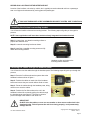
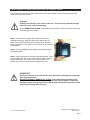
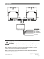
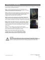
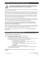
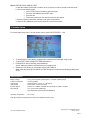
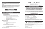
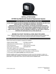
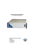
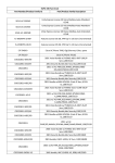
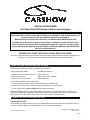
INSTALLATION GUIDE
Car Show Dual DVD Headrest Replacement System
NOTICE OF INTENDED INSTALLATION AND USE
E
CAR SHOW VIDEO PRODUCTS ARE NOT INTENDED FOR VIEWING BY THE DRIVER, AND ARE TO
BE INSTALLED ONLY TO BE VIEWED BY REAR-SEAT OCCUPANTS.
IMPROPER INSTALLATION COULD DISTRACT THE DRIVER OR INTERFERE WITH SAFE
OPERATION OF THE VEHICLE, WHICH COULD RESULT IN SERIOUS INJURY OR DEATH, AND
COULD ALSO VIOLATE STATE LAW. CAR SHOW DISCLAIMS ANY LIABILITY FOR ANY BODILY
INJURY OR PROPERTY DAMAGE THAT MAY RESULT FROM ANY IMPROPER OR UNINTENDED
INSTALLATION AND/OR USE.
BEFORE YOU START THE INSTALLATION, READ THIS GUIDE!
Car Show “Headrest DVD” systems are the easiest-to-install DVD entertainment systems available today.
However, we strongly recommend reading this guide before starting the installation!
1 Make sure you have the tools you will need
These common items are needed to complete this installation:
· Digital multimeter (DMM)
· #2 Phillips screwdriver
· Appropriate tool for headrest removal · Allen wrench set
· Panel removing tools
· Cable routing tool (included)
· Security latch tool (included)
· Retractable knife
· Wire cutters, strippers, and a crimping tool
· 1/4” drive sockets are often needed for dashboard and trim disassembly
· Check if Torx or Allen-drive bolts are used on any panels you will be removing
· You will need a DVD in good condition when testing the system
Standard installation parts you will need include wire, wire ties, wire crimp connectors or solder, and
electrical insulating tape. Installation of aftermarket automotive electronics also often requires access to
special parts. It is a good idea to have a source for these common installation parts.
2 Inspect the vehicle and plan your work
k
CHECK THE BATTERY
Test the battery voltage to make sure it’s fully charged and inspect battery terminals for tightness and any
corrosion. This only takes seconds and can save hours of troubleshooting later.
Car Show Installation Guide
Copyright 2011 All Rights Reserved
CS005 Rev A
Page 1
DECIDE ON A LOCATION FOR THE INTERFACE UNIT
Location of the interface unit varies by vehicle, but is typically secured underneath a driver or passenger
seat out of sight and unobstructed by moving parts and passengers.
IF YOU HAVE PURCHASED A PRE-ASSEMBLED HEADREST SYSTEM, SKIP TO SECTION 6
3 Installing the electronics mounting bracket
You will need to install the electronics mounting bracket. The following steps will guide you through this
process.
NOTE: Some applications will have these brackets already integrated into headrest bucket!
Step 1: Locate clean, non-abrasive working surface to
prepare the headrest units.
Step 2: Locate the mounting bracket as shown.
Step 3: Install the 4 supplied mounting screws to fully
attach the mounting bracket
Headrest cushion with electronics
mounting bracket installed
4 Running the cables through the headrest posts
You will need to route the cables through the headrest posts. The following steps will guide you through this
process.
Step 1: Place the Car Show electronics system above the
headrest bucket as shown in figure 1.
Step 2: Position the cables on each side of the headrest
bucket and ensure they are smooth without kinks or knots.
Fig. 1
Step 3: Route the cables through the headrest posts, being
careful not to cross the cables.
Step 4: Position the Car Show electronics unit in the
headrest bucket while constantly pulling the cable through
the headrest posts (see figure 2). This step is critical to
prevent damage to the cables or Car Show unit.
Fig. 2
IMPORTANT!
Do NOT allow the cables to cross over one another or leave excess cable slack in the
headrest bucket. This will prevent the unit from closing properly, could permanently
damage the unit.
Car Show Installation Guide
Copyright 2011 All Rights Reserved
CS005 Rev A
Page 2
5 Mounting the Car Show electronics into the headrest bucket
You will need to mount the Car Show electronics unit into the headrest bucket. The following steps will
guide you through this process.
to the LCD
CAUTION!
Do NOT press directly on the surface of the LCD. This will cause permanent damage
which will not be covered by warranty.
Always REMOVE ANY SLACK in the cables during assembly. Failure to follow this step may
cause damage to the cables.
Step 1: Place the lower edge of the Car Show unit into the
headrest bucket first. Be sure that the lower edge of the Car
Show unit does NOT go below the top surface of the headrest
bucket (see figure 3). Use caution so the material on the bucket is
not damaged.
Fig. 3
Step 2: Pull any additional slack created in the cables through
the headrest posts.
Step 3: Align electronics on electronics mounting bracket. Push
firmly, the side latch will “click” to lock monitor in place. Remove
excess cable slack! Use caution NOT to press on the LCD
surface as this can cause permanent damage to the LCD.
IMPORTANT!
Do not force electronics into the bracket, the components are designed to easily align
when properly installed.
BE 100% CERTAIN TO REMOVE ALL SLACK in the cables during assembly of the
units. Failure to follow this step may damage the unit, internal cables or prevent the
unit from properly closing. If you feel resistance when closing the unit, please confirm
that all cable slack has been removed.
Car Show Installation Guide
Copyright 2011 All Rights Reserved
CS005 Rev A
Page 3
Wiring diagram
Gray
Black
REMOTE
AUX 2
FMM OUTPUT
IR A
A/V OUTPUT
Gray
MONITOR A
IR B
A/V OUTPUT
Black
MONITOR B
POWER
Interface Harness
Red – 12V ACC (switched)
Black – Ground
Gray – 12V Switch-FMM
Black – Ground-FMM
Blue – 12V (Aux source)
Black – Ground (Aux source)
Purple – Antenna
6 Removing the factory headrests
IMPORTANT!
Do NOT start this step until you have inspected the seats and factory headrests for any
obstructions.
You will need to remove the existing factory headrests. The following steps will guide you through this
process.
Step 1: Determine if a locking device is present on the factory headrest. Locking devices are usually
a button or small push pin located at the base of the headrest post(s).
Step 2: If a locking device is present, press and hold the lock release, and pull firmly upward on the
headrest. If no locking device is visibly present refer to the vehicle’s owners manual or the vehicle’s
manufacturer for further instructions.
Car Show Installation Guide
Copyright 2011 All Rights Reserved
CS005 Rev A
Page 4
7 Installing the Car Show headrests
You will need to install the Car Show headrests and route the cables through the seat backs. The following
steps will guide you through this process.
Step 1: Check the headrest down tubes in the seat backs for any
obstructions. Normally the down tubes are clear and allow the Car Show
cables to exit from the bottom of the down tubes.
Step 2: Position the Car Show headrest so the monitor will be facing the
rear of the vehicle once properly installed. Then drape the cables over the
seat back, being sure that the cables are NOT crossed. Place the
headrest safely on the seat cushion (see figure 6).
Step 3: Attach the cable routing tool to a cable. Slowly feed each cable
routing tool through its corresponding down tube until the ends of the
cable routing tool is visible at the bottom of each seat back. Pull the cable
until it extends out the base of the seat back. Repeat for the second cable.
Fig. 6
Step 4: Remove the cable slack until only ½ inch is showing. Insert the
headrest into the down tubes. This step normally takes some moderate
force, and may be eased by using a very light lubricant on the posts. Be
certain to pull lightly on the cables as the headrest is inserted to remove
excess slack.
Step 5: Once the headrest is fully seated in the down position
(see figure 7), place a small service loop (6”-12”) of cable in the seat
back, to allow the headrest to easily adjust up or down.
Fig. 7
Step 6: Connect the interface cable to the monitor cable,
ensuring that the cables are matched gray-to-gray and blackto-black. Properly route the cables to ensure they are secured,
out of sight and unobstructed by moving parts and passengers.
CAUTION!
Use caution when pulling on the cables as some seats may have sharp edges or
objects in the seat back which could damage the cables. Sometimes it is necessary to
remove or partially remove the seat back covering to properly install the cables.
Car Show Installation Guide
Copyright 2011 All Rights Reserved
CS005 Rev A
Page 5
8 Routing the harnesses and making the wiring connections
It is the installer’s responsibility to ensure that the safety equipment in the vehicle is
NOT adversely affected by installation of this system. Ensure that the routing of the
harnesses does NOT obstruct airbags, SRS or other safety devices.
You will need to route the harnesses and make the power connections to the vehicle. The following steps
will guide you through this process.
Step 1: This system requires a minimum of 12V (+) ACC Switched and Ground (-) to operate. The 12V (+)
ACC Switched source must be capable of supplying a minimum of 7A. These can be found at multiple
points in the vehicle. The Ground (-) should be located at a Factory Chassis ground point when possible.
Step 2: Select a location to mount the junction box for the Car Show units. Normally the junction box is
best located under either the driver or passenger seat. Be sure to locate it so that it will not obstruct any
moving parts in the seat or damaged by the feet of passengers.
.
Step 3: Route the power harness to the dash area where you have located the 12V (+) ACC connection
point. Be sure to protect the cable from any potential sharp edges which could damage the harness in the
future. To avoid vibration noise, use tape to secure the harness whenever possible.
Step 4: Route the FMT antenna wire (purple) toward the antenna/tuner. (Be sure to separate it
from the power wires and avoid any power seat modules or other vehicle harnesses as these
may induce noise into the FM transmission.)
Step 5: When connecting the power harness, Rosen recommends soldering all connections. When using
T-Tap or crimp connectors, always ensure the connections are made with the proper gauge connectors.
Failure to make a proper connection will result in a system failure in the future.
Step 6: With ACC off, plug all harnesses into the main interface unit. Note: Plug the main power
harness in last.
9 Initial test, reassembly, and pre-delivery re-test
You will need to fully test the system to ensure it is working and connected to the vehicle properly. The
following steps will guide you through this process.
Step 1: INITIAL TEST (Do this BEFORE you reassemble any trim panels)
a. Reconnect the vehicle battery if needed
b. Install batteries into the remote control, and wireless headphones
c. Start the vehicle (ensure that it is safe to do so, there are no tools or people under the hood)
d. Perform the following steps on each headrest to ensure proper operation:
• Close and re-open the unit several times
• With the display open, insert a DVD (in good condition) and select play
• Check the audio on the IR headphones
• Press the Speaker button and adjust the vehicle radio frequency as needed to
check the audio
• Eject the disc
• Turn off the vehicle and wait for the unit to turn off
e. If the system does not function properly, reset the system by pressing and holding the reset
button located near the eject button
Step 2: REINSTALL all trim panels removed during the installation using care not to damage any
harnesses
Car Show Installation Guide
Copyright 2011 All Rights Reserved
CS005 Rev A
Page 6
Step 3: PRE-DELIVERY AND RE-TEST
a. Start the vehicle (ensure that it is safe to do so, there are no tools or people under the hood)
b. Perform the following steps
• Insert a DVD (in good condition) and select play
• Re-check IR headphones and FMT audio
• Eject the disc
• Remove the protective films and clean the unit as needed
c. Place the Owners Information package in the glove compartment
d. Place the IR headphones and remote control in a convenient location
10 Installer Setup
To access install setup menu: use the remote control, press EJECT-ENTER-1-1-2-0
•
•
•
•
To change AUX 2 input labeling, highlight AUX 2 label and scroll left/right using arrows.
To select EXT FMM, highlight EXT FMM and select on.
POD ADDR is used to manually set pod address
AutoÆ address is based on which port the pod is plugged into.
Selecting A or B allows you to manually set the pod’s address
When manually selecting POD ADDR, an OSD will appear on opposite pod displaying what pod it
will be
Specifications
Supply Voltage
Current Consumption
Video Signal
Audio Signal
IR Audio Signal
Discs Played
:
:
:
:
:
:
12V (+) ACC negative ground system, 11-16VDC operating range
7A max operating
Composite video 1.0Vp-p 75 , NTSC/PAL
Audio Output : 2Vrms, line output
Channel A= 2.3 MHZ / 2.8 MHZ and Channel B= 3.2 MHZ / 3.8 MHZ
(1) 5” (12cm) DVD-VIDEO Disc
(2) Compact Disc (CD-DA/CD-R/CD-RW/MP3)
Operating Temperature
: 0C to +60C
Note: Specifications and designs are subject to modification without notice.
Car Show Installation Guide
Copyright 2011 All Rights Reserved
CS005 Rev A
Page 7
FAQ’s
The monitor cables get stuck in the posts
Normally the cables will slide through the posts with very little effort. However, if you encounter difficulty,
please check the following:
Solution: Ensure that there are no obstructions inside the post.
Solution: Ensure that there are no metal burs at the entrance or exit of the posts.
Solution: Ensure that there are no kinks or knots in the cables.
Solution: Use a cable pulling lubricant.
The monitor does not fit into the headrest bucket
The Car Show unit has been designed to fit tightly into the headrest bucket. This was done to ensure a
high quality fit with no gaps.
Solution: Use a mild soap and water solution to LIGHTLY moisten the mating surface of the
headrest bucket. CAUTION! – Do not get water on or in the electronics as damage WILL result
which will not be covered by warranty.
The FMT does not transmit audio
The system is designed to use either the internal FM Transmitter or an external FM Modulator. Select the
mode in the installation set up menu.
Solution: Check the FMT configuration to be sure that FMM is set to OFF. FMT is the default.
Resetting the system
It is a good practice to reset the system immediately after Power is FIRST connected.
Solution: To reset the system, open the DVD unit and locate the small reset button next to the
Eject button. Press and hold the Reset button for 3 or 4 seconds.
Finding the best Power Point
Avoid connection to wires which supply the following: fan/seat/mirror motors power, excessively large sized
wires, glow plug power lines, radio power lines, defroster power lines, etc.
Solution: Open power points can be located in the fuse box, which are designed for accessory
equipment.
The DVD restarts when the vehicle is started
When the vehicle is started, the DVD should resume from previous point. However, if the voltage falls below
10VDC during cranking, the system will restart at the beginning of the DVD.
Solution: Check if the battery is fully charged. New vehicles rarely have a fully charged battery.
Solution: Older batteries can not provide the necessary voltage during an engine cranking.
Vehicle battery may need replacement.
Solution: Extreme climate conditions (cold or hot) will reduce the efficiency of the battery. Be sure
the battery is fully charged and in good condition. Replace the battery if needed.
The System Stays On and Never Shuts Off
The System is designed to turn off when the key is turned off. If the ACC (Red) wire is connected to a
constant 12VDC (+) power point the system will system will stay on until the battery dies.
Solution: Check the ACC connection point to be sure it is switched with the key, and relocate as
needed.
No headphone audio
The Headphone audio should be preset at all times, unless the MUTE is set to on, or a DVD Setting has
been changed in the DVD Settings Menu.
Solution: Press the MUTE Button to enable the audio and turn the MUTE OFF.
Solution: Confirm the headphones have fresh batteries, are turned on, and the ON LED Indicator
is Illuminated.
Solution: Check the DVD Setting and restore them to FACTORY SETTINGS if needed (see the
Owners Manual).
Car Show Installation Guide
Copyright 2011 All Rights Reserved
CS005 Rev A
Page 8
Selecting FMM pre-sets
For best operation, the FMM Pre-set selection should be on a station which is not in use or has weak
broadcast in your area.
Solution: You can also check www.RosenDealerCentral.com. This site provides you with the best
stations in your local area. Select a corresponding FMM Station when available.
Reducing audio or video noise
Audio or video noise may be induced into the system from sources ranging from harness location, power
point to poor grounding.
Solution: Re-route the wire harnesses to avoid passing over other harnesses or near electrical
motors.
Solution: Try relocating the ground point to factory ground point or factory ground wire.
Solution: In some cases, inline audio filters may be required. Contact Rosen for support on
selection of a filter.
Missing Channel B Audio
System includes a monitor A and monitor B. Monitor A is channel “A” on headphones and monitor B is
channel “B” on headphones. If audio is not present, check the following.
Solution: Check A/B switch on headphones.
Solution: Reset the system
Solution: Check all cable connections
Solution: Please refer to “Install Set-up Menu”.
Solution: Force channel B via Installer Setup menu
Service and optional parts list
Part Number
Description
Part Number
Description
AP1043
CS003
AC3640
AP1008
AP1010
AP1012
AC3196
AP1015
IR Remote Control
Owner’s Manual
2 Channel IR Headphones
Power Harness
Interface Extension Harness
Remote IR Harness
External Wired FMM
Mounting Bracket
AP1016
CS007
AP1041
AP1042
AP1011
AP1019
CS004
Tool, Monitor Release
Interface Module
Monitor Black Harness
Monitor Gray Harness
Monitor Aux Harness
Hardware Pack
Quick Reference Card
Car Show Installation Guide
Copyright 2011 All Rights Reserved
CS005 Rev A
Page 9