1
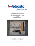
Installation & Operation Manual
KIT P/N: 300101 and 300202
Installation / Operation Manual
Seat Comfort
Contents
Contents.................................................................................................................................. 3
Warnings: ................................................................................................................................ 4
Notice To Users Of Carbotex Seat Heating Systems:............................................................... 5
Safety Advice:....................................................................................................................... 5
Package Contents .................................................................................................................... 5
Disclaimer ................................................................................................................................ 6
Introduction ............................................................................................................................. 7
Important Notice ...................................................................................................................... 7
Installation Steps ...................................................................................................................... 8
Technical Assistance ............................................................................................................... 14
Limited Warranty.................................................................................................................... 15
3
Installation / Operation Manual
Seat Comfort
Warnings:
Carbotex aftermarket Seat Heater Systems are not designed as a “do-it-yourself“ installation products!
To enhance safety and assure a high level of electrical contact of wires, simple cable/wire connectors (squeeze type
splicing, etc.) cannot be used in this installation. All connections must be soldered and properly insulated
afterwards.
Always consult the vehicle wiring diagram when unsure about individual wire/power source identification.
Only use the parts and components supplied in the installation kit for the seat heater installation. The supplied
components are carefully tuned and adjusted for optimal interaction. Foreign parts may lead to changes in current
flow and other problems thus resulting in potential damage.
The seat heater can only be used to heat the front seats of the vehicle.
The installation of the heating pads must be free of creases and wrinkles.
Always operate the two individual heating pads in conjunction and connected to the same 12 Volt DC vehicle
power source. Individual connection and operation of the heating pads is prohibited.
The side to side (width) of the heating pads must not be altered (cutting not permitted). Only cutting of the
segments for the attachment of the seat covers is permitted. To do this, please follow the instructions in the
corresponding segment of this guide.
Installation of Webasto seat heaters in cars with seat containing seem lines running front to rear (length wise) is not
permitted unless the heating pads are not directly located over a seat groove which would interfere with the
installation and function of the device.
After the installation of the wire harness of the seat heater it must be assured that all designed seat motions are still
possible without obstruction and the moving of the seat is not causing any interference and damage to the seat
heater harness.
Seats in vehicles with pre-loaded (power charge equipped) safety belts must be removed and re-installed under
strict adherence to the vehicle manufacturers instructions.
In case your seat is equipped with a side impact air bag (usually installed in the armrest facing the door), assure that
you:
- Leave the original seat seems intact and unmodified
- locate the heating pad only in the center of the foam part of the seat
- Strictly adhere to the instructions provided in the manufacturer’s owners manual
for the vehicle
In cases where a seat is fitted a pressure sensor, please refer to the manufacturers manual for any specific
instruction with regard to the installation of seat heaters.
The heating temperature is varying depending on the structure of the seat-cover material. Please keep in mind that
thicker cover-materiel is less pervious to the heat.
If the original seat-covers are glued, you can only fit the seat-heating-system using an additional seat-cover, a
removal and repeat use of the original seat-cover is not possible
4
Installation / Operation Manual
Seat Comfort
Notice To Users Of Carbotex Seat Heating Systems:
The seat heater is designed to control the temperature of the lower and upper seat segment of the front seats.
Proper temperature control of the vehicle seat increases the driver‘s comfort and enhances your basic health. The
seat heater operates in two power levels and can only be engaged with the ignition turned on. The switch label
“HI“ denotes the function best used to power up the seat heater in cold ambient temperatures. After the
system is running for a while the seat heater should be switched to the “LO“ position for maximum comfort. This
keeps the system from generating too much heat when running continuously.
The seat heater is equipped with safety device which senses and prohibits overheat conditions. If the seat heater is
operated for extended times in the HI position, it may be possible for the thermo probe to shut the heater down. In
such event it may take a few minutes until the system will re-engage again without action needed from the driver
(provided the switch is still in the on position). A 10 Amp fuse protects against electrical shorts and other
malfunctions. This fuse is located behind the seat heater switch. To check or replace the fuse, lift the switch out of
the case and expose the fuse socket for review.
Safety Advice:
•
Do not place any heavy, sharp or pointed objects on the seats
•
Any fluid spilled on the seats may destroy the seat heater and may cause damage to the
•
vehicle. Never operate the seat heater while the seats are wet or soaked with fluid.
•
Do not keep insulating material (sheets, covers, coats) on the seats while the seat
•
heater is running. Do not place heat sensitive objects on the seats while the seat heater is running.
•
To protect damage and discharge of the battery, avoid seat heater operation for extensive time periods
without a running engine.
•
Individuals, extra sensitive to heat, should only operate the seat heater in the “LO“ position.
Package Contents
Components list / supplied with the “Carbotex-Universal-Seat-Heater-System“ kit:
Qty.
Component / Part
1
Carbotex-Heating Element (pads) with automatic thermo protector (Dual pads kits are also available)
1
Wire harness with integrated fuse socket (incl.10Amp-fuse)
1
Seat heater switch
2
Installation tape (black - 300 mm)
4
Double stick adhesive tape (yellow - 280 mm)
1
Installation template (switch location, self adhesive)
1
Installation instructions
1
Owners manual (directions for operation, use & care)
5
Installation / Operation Manual
Seat Comfort
Disclaimer
The installation instructions must be followed with utmost diligence by trained and properly qualified specialists as
failures to comply (or mistakes during the installation phase) may cause damage to the system, the vehicle and may
potentially impose harm to drivers and/or passengers.
6
Installation / Operation Manual
Seat Comfort
Introduction
Carbotex after market seat heater systems are ideal comfort additions to the front seat of every vehicle. Soon after
the driver and passenger have experienced the advantages of a seat heating device, the accessory will be used and
valued year round and not only during the cold winter month.
Important Notice
In cases where the individual vehicle fit of the Carbotex seat heater appears uncertain, review and check the
required fit size of the heating pads for the individual seats. In such a case always refer to the provided template
prior to installation.
7
Installation / Operation Manual
Seat Comfort
Installation Steps
1
Removal of seat
Secure the vehicle on a level and plane parking area.
Remove the front seat that the seat heater is to be installed. Refer to
the vehicle manufacturers recommended service procedure for proper
removal of seat.
2
Preparation for the electrical wire connection
Disconnect the battery prior to any activities with the vehicle wiring
system. Follow the vehicle manufacturer guidelines when
disconnecting the battery.
Remove the center console in the region where it sits above the
gear/drive train channel.
Remove the plastic cover underneath the steering column.
3
Installation of seat heater-switch (Rectangle Switch Only)
Select a proper and convenient location for the switch and assure that
the location has ample space for the switch, the switch case, the
connectors, attached wire harness and the fuse.
Mark the location for the switch. Make sure not to cut the hole to
large as this will cause a loose unfashionable appearance.
Cut-out of the outlined/marked area for the switch. Assure that the
cut-out area is neither too small (side pressures of material may be
compressing the switch housing thus causing potential malfunction) nor too large (may create improper seating of the switch and the
housing, wiggling, etc.).
4
Routing the wire harness (Rectangle Switch Only)
Assure that the location and positioning of the wire harness for the
seat heater does not interfere with the seat motions. Any chafing,
rubbing, stretching and other stress on the harness may result in
damage to the seat heater as well as partial or totally impaired seat
motion. Use cable ties to affix the wire harness. Follow the harness
installation as follows:
Run the 5-prong connector through the cut-out section where the
switch will be located and begin routing the harness. Assure that the
harness is long enough to make unrestricted contact with the
connector and the switch when both components are connected. Run
the wire harness with the two white prong connector/plugs
underneath the carpet to reach the individual seat. Allow for generous
wire length to assure unrestricted seat movement (zero wire
stretching).
Route the harness towards the power source ensuring the harness is
protected from damage at all times.
8
Installation / Operation Manual
5
Seat Comfort
Electrical connection (Rectangle Switch Only)
Mount the seat heater switch in a convenient location. Position the
switch so that the marking “HI“ faces to the front of the installation.
Positive power connection:
Connect the positive wire to an ignition power source.
Note: Make absolutely certain that the vehicle electric and power lay
out can support the seat heater power requirements. If
necessary, utilize a relay.
Negative power connection:
Attach the ring connector on the brown wire coming from the seat
heater harness to a suitable ground source on the vehicle.
Affix the seat heater harness with cable ties and assure that all seat
movement is still possible.
6
Re-install the covers and moldings that were removed during the
harness routing. Assure that all connector and plugs are re-connected.
Check for proper function.
Optional Switch and Harness Instructions
Installation of optional seat heater-switch (round switch)
Select a proper and convenient location for the switch and assure that
the location provides enough space to mount the switch, switch case,
the connectors, relay and connector, attached wire harness and the
fuse. Mark the location for mounting the switch. Drill an approximate
¾” hole for mounting the switch. Assure that the mounting hole is
not too small (side pressure compressing the switch causing potential
malfunctions) nor to large of an opening (improper seating the switch
causing poor or loose fit, etc).
7
Routing the wire harness
Assure that the location and positioning of the wire harness for the
seat heater does not interfere with seat motions. Any chafing,
rubbing, stretching and/or any stress on the harness may result in
damage to the seat heater as well as partial or total failure of seat
motion. Use cable ties to attach the wire harness. Follow the
harness installation as follows:
With the switch mounted into position, connect the 3 pin connector
from the switch to the harness side 3 pin connector. Assure that the
harness is long enough to make unrestricted contact with the
connector and the switch.
Route the wire harness with the two white prong connectors under
the carpet to reach the individual seat. Allow for as much wire length
as possible to assure unrestricted seat movement.
Run the wire harness with the red and black ground wires to the
nearest ignition source.
9
Installation / Operation Manual
8
Seat Comfort
Electrical connection
Positive power connection:
The connection is always to the ignition positive power.
Note: Make sure that the vehicle electrical system can support the seat
heater power requirements. Firmly solder the red wire from the seat
heater harness to the vehicle wire/connector. Assure proper insulation
of the connector area.
Negative power connection:
Attach the ground eyelet on the black ground wire from the seat
heater harness to a known good ground.
Mount the relay in an inconspicuous area so that moisture from the
Carpet will not affect operation. Be sure that the relay and harness do
not interfere with the motion of the seat or cause any strain on the
harness when the seat is moved. Be sure that there is enough room to
mount the relay with the connector attached.
Attach the seat heater harness with the cable ties and assure that all
necessary movement is still possible.
Assure that all connectors and plugs are re-connected. Check for
proper function.
9
Installation of heating pads
Position the removed vehicle seats on a proper work bench/table etc.
Remove all side covers, moldings and outer parts/accessories.
Disassemble the seats lower pad and back rest and remove from seat
frame by removing the attachment screws.
Move the lower seat pad and remove all upholstery clamps (holding
this seat cover in place). Ware safety goggles during the procedure.
10
Make certain not to overlook any clamps or hard parts in the removal
process as these parts and sharp objects may cause damage to the
seat and the seat heater pads.
Measure the width of the center seat segments (lower part and back
rest) between the longitudinal seems. The width must be at least
250 mm. It is very important that the heating pads do not contact the
side seems. The seat heater cannot be installed if this is the case.
10
Installation / Operation Manual
11
12
13
14
Seat Comfort
Position the heating pad with the label facing down and the wire
harness facing towards the rear of the vehicle seat. Adjust the pad in a
way that the safety thermo protector incorporated in the heating pad
is located approx. 2-5 cm forward of the back rest. In cases where the
seat cushion contains lateral grooves (side to side) to
accommodate the seat cushion seems, the heating pad must be
positioned in order to follow the contours of the vehicle seat cushion.
The heating pad must be cut out in the areas where lateral seems are
connecting the grooves in the cushion. This allows for the
reinstallation of the seat-cover upholstery clamps. To mark these areas
on the seat heater pads use a magic marker and draw lines on the
heating pad identifying the beginning and the end of the underlying
grooves.
After marking the heating pad, pull it out of the groove and measure
the distance on each side of at least 40mm. It is necessary to keep this
40mm distance to the sides so the electric supply will not be damaged.
Cut out the marked area with suitable scissors.
11
Installation / Operation Manual
15
16
17
Seat Comfort
Insulate the lateral "bridges", which protrude out from the previously
cut area, with the supplied black insulation tape. Assure proper
insulation.
Position the heating pads on the foam seat pad. Assure that the
insulated segments of the seat heater pads align with the grooves in
the foam cushion. The heating pad must not overlay the side seems.
After the seat heater pad is properly adjusted to the vehicle seat (foam
pad) make the final length determination.
Make sure that the length difference between the seat pad and back
pad does not exceed 75 mm. This ensures that there is no uneven
temperature distribution between both pads.
The seat heater pad should reach the forward edge of the seat
cushion. Cut accordingly and affix with double sided adhesive tape.
18
To assure proper fit and reduced interference with the seat foam, cut
out (use sharp knife) a square segment in the foam of the seat in the
area of the thermo protector.
After the heating pad is positioned, affix it with the adhesive strips in
the pad area where the wire harness is routed.
12
Installation / Operation Manual
19
Seat Comfort
For safety reasons you should protect those danger spots with suitable
material (i.e. insulation tape or shrinkable hose)
Careful not to damage seat heater when reinstalling upholstery
clamps.
Run the harness from the seat heater pads in a way that it exits the
seat to prevent harness exposure.
Use same procedures when running wires and harnesses (seat heater
pad upper back rest segment) from the back rest of the seat.
20
Installation of the vehicle seat / Function check
Re-assemble seat(s), accessories, and re-install seat(s) in the vehicle per
manufacturer’s service procedures.
Connect the wires from the two seat heating elements (lower pad and
back rest) to the wire harness that rests under the vehicle seat
assembly. It does not matter which wire connects to which side (both
elements receive same power).
Ensure proper fit and connection between plugs and receptors. Attach
the connectors and the harness to the seat frame to avoid interference
with moving parts. Assure seat function (without obstruction)
Reconnect the battery and check the function of the seat heater
system and re-check all other systems where components were
removed during the installation process.
A harness integrated fuse housing is located directly behind the seat
heater switch. Check that the 10 Amp flat fuse is in place and in
working order.
Assure that the owner receives proper information and instructions
about the operation, care and trouble shooting of their new seat
heater system. Make sure the owner knows the location of the 10
Amp fuse in case that a replacement is required. Hand out the owners
manual and instructions for the Carbotex seat heater
system.
13
Installation / Operation Manual
Seat Comfort
Technical Assistance
If you require help, check our technical assistance website at http://www.techwebasto.com or call the technical
support hotline at (800) 860-7866.
14
Installation / Operation Manual
Seat Comfort
Limited Warranty
Webasto carries a 3 year or 36,000 miles driven limited warranty beginning from the date of installation. The
warranty covers proven fabrication and materials deficiencies.
Not covered in the warranty are damages resulting from:
•
•
•
•
•
Improper handling of components and seat heater systems
Failure to follow installation instructions
Unauthorized installation
Installations by staff not qualified or certified to do the installation
Transportation and freight
The warranty covers only material. Subsequent damage of any kind, even as result of damage or flawed
components (supplied by vendor) is not covered.
The vendor‘s warranty procedures must be followed to become eligible for a claim. The vendor reserves the
discretionary right to determine whether the defective unit will be repaired, replaced entirely or whether only
components will be sent to correct the defects.
All freight, packaging and other associated cost must be covered by the buyer. Vendor reserves the right to conduct
repairs of defective units either at the location of the buyer or any other location specified, agreed and
communicated between the vendor’s place of business and the buyer. Potential transport and freight cost must be
covered by buyer unless otherwise specified by vendor.
Only such warranty claims can be processed and honored, where buyer provides the vendor at the time of the claim
with the following documents –
•
•
•
•
Proof of purchase (invoice)
Proof of payment
Proof of installation by authorized and qualified installer (following published installation guide lines and
directions) incl. mileage reading at the point of installation.
Both labels on the seat heater system‘s heater pads must contain comprehensive vehicle data like year,
make and model of the car as well as the date of seat heater system Installation.
15
Webasto Product N.A., Inc.
Technical Assistance Hotline
Phone: (800) 860-7866
www.webasto.us
www.techwebasto.com