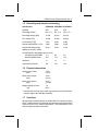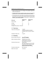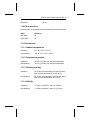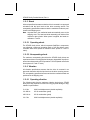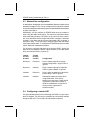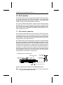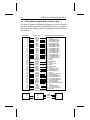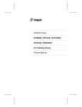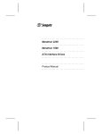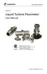
1
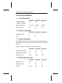
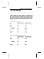
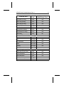
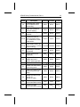
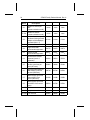
..................................... ST9655 Family ..................................... ST9655AG, ST9550AG ..................................... ST9385AG ..................................... ATA Interface Drives ..................................... Product Manual ..................................... ..................................... ST9655 Family ..................................... ST9655AG, ST9550AG ..................................... ST9385AG ..................................... ATA Interface Drives ..................................... Product Manual ..................................... 1994 Seagate Technology, Inc. All rights reserved Publication Number: 36270-001, Rev. A September 1994 Seagate®, Seagate Technology® and the Seagate logo are registered trademarks of Seagate Technology, Inc. Other product names are registered trademarks or trademarks of their owners. Seagate reserves the right to change, without notice, product offerings or specifications. No part of this publication may be reproduced in any form without written permission from Seagate Technology, Inc. ST9655 Family Product Manual, Rev. A iii Contents 1.0 Drive specifications . . . . . . . . . . . . . . . . . . . . . . 1 1.1 Formatted capacity . . . . . . . . . . . . . . . . . . . . . 1 1.2 Physical organization . . . . . . . . . . . . . . . . . . . . 1 1.3 Logical organization . . . . . . . . . . . . . . . . . . . . . 1 1.4 Default logical geometry . . . . . . . . . . . . . . . . . . . 1 1.5 Recording and interface technology . . . . . . . . . . . . . 2 1.6 Physical dimensions . . . . . . . . . . . . . . . . . . . . . 2 1.7 Seek time . . . . . . . . . . . . . . . . . . . . . . . . . . 2 1.8 Start times . . . . . . . . . . . . . . . . . . . . . . . . . . 3 1.9 Reliability . . . . . . . . . . . . . . . . . . . . . . . . . . 3 1.10 Drive acoustics . . . . . . . . . . . . . . . . . . . . . . . 4 1.11 Environment . . . . . . . . . . . . . . . . . . . . . . . . 4 1.11.1 Ambient temperature . . . . . . . . . . . . . . . . . 4 1.11.2 Temperature gradient . . . . . . . . . . . . . . . . . 4 1.11.3 Relative humidity . . . . . . . . . . . . . . . . . . . 4 1.11.4 Altitude . . . . . . . . . . . . . . . . . . . . . . . . 4 1.11.5 Shock . . . . . . . . . . . . . . . . . . . . . . . . . 5 1.11.6 Vibration . . . . . . . . . . . . . . . . . . . . . . . . 5 1.12 Power specifications . . . . . . . . . . . . . . . . . . . . 6 1.12.1 Power management . . . . . . . . . . . . . . . . . . 6 1.12.2 Power consumption . . . . . . . . . . . . . . . . . . 8 1.12.3 Conducted noise . . . . . . . . . . . . . . . . . . . 10 1.12.4 Voltage tolerance . . . . . . . . . . . . . . . . . . . 10 1.13 Agency certification . . . . . . . . . . . . . . . . . . . . 10 1.13.1 UL/CSA listing . . . . . . . . . . . . . . . . . . . . . 10 1.13.2 FCC verification . . . . . . . . . . . . . . . . . . . . 10 1.14 Compatibility notes . . . . . . . . . . . . . . . . . . . . . 11 1.14.1 ECC testing . . . . . . . . . . . . . . . . . . . . . . 11 iv ST9655 Family Product Manual, Rev. A 2.0 Drive mounting and configuration . . . . . . . . . . . . . . 13 2.1 Handling and static-discharge precautions . . . . . . . . . 13 2.2 Mounting the ST9655 family drives . . . . . . . . . . . . . 13 2.3 Master/slave configuration . . . . . . . . . . . . . . . . . . 15 2.4 Configuring a remote LED . . . . . . . . . . . . . . . . . . 15 3.0 ATA interface . . . . . . . . . . . . . . . . . . . . . . . . . 17 3.1 ATA interface connector . . . . . . . . . . . . . . . . . . . 17 3.2 ATA interface signals and connector pins . . . . . . . . . . 18 3.2.1 AT bus signal levels . . . . . . . . . . . . . . . . . . 19 3.3 ATA interface commands . . . . . . . . . . . . . . . . . . 20 3.3.1 Identify Drive command . . . . . . . . . . . . . . . . 22 3.3.2 Set Features command . . . . . . . . . . . . . . . . . 26 3.3.3 Rest/Resume commands . . . . . . . . . . . . . . . . 27 ST9655 Family Product Manual, Rev. A v Figures Figure 1. Typical startup and operation current profile for the ST9655AG . . . . . . . . . . . . . . . . . . . . . . . . 9 Figure 2. Typical startup and operation current profile for the ST9550AG and ST9385AG . . . . . . . . . . . . . . . . 9 Figure 3. Mounting dimensions for the ST9655 family drives . . . . 14 Figure 4. Master/slave jumpers for the ST9655 family drives . . . . 16 Figure 5. ATA interface connector for the ST9655 family drives . . 17 ST9655 Family Product Manual, Rev. A 1 1.0 Drive specifications 1.1 Formatted capacity ST9655AG ST9550AG ST9385AG Guaranteed Mbytes (1 Mbyte = 106 bytes) 524 455 341 Guaranteed sectors 1,024,128 889,248 666,876 Bytes per sector 512 512 512 ST9655AG ST9550AG ST9385AG Read/Write heads 8 8 6 Discs 4 4 3 1.2 Physical organization 1.3 Logical organization The ST9655 family drives support all head, cylinder and sector geometries, subject to the maximums specified below, and to the following condition: (sectors) × (heads) × (cylinders) ≤ total sectors per drive ST9655AG ST9550AG ST9385AG Sectors per track (max) 64 64 64 Read/Write heads (max) 16 16 16 Cylinders (max) 1,024 1,024 1,024 ST9655AG ST9550AG ST9385AG Sectors per track 63 59 51 Read/Write heads 16 16 14 Cylinders 1,016 942 934 1.4 Default logical geometry 2 ST9655 Family Product Manual, Rev. A 1.5 Recording and interface technology Specification ST9655AG ST9550AG ST9385AG Interface ATA ATA ATA Recording method RLL (1,7) RLL (1,7) RLL (1,7) Recording density (BPI) 72,100 59,124 59,124 Flux density (FCI) 44,360 44,360 44,360 Track density (TPI) 3,227 3,282 3,282 Spindle speed (RPM ± 0.5%) 3,980 3,980 3,980 Internal data transfer rate (Mbits per sec max—ZBR) 28.26 27.28 27.28 11.1 13.3 8.0 13.3 8.0 13.3 Interleave 1:1 1:1 1:1 Cache buffer (Kbytes) 120 120 120 I/O data transfer rate (Mbytes per sec max) PIO Mode 3 with IORDY Multiword DMA Mode 1 1.6 Physical dimensions Height (max) inches (mm) 0.754 (19.15) Width (max) inches (mm) 2.760 (70.10) Depth (max) inches* (mm) 4.010 (101.85) Weight (typical) ounces (kg) 7.4 (0.21) * Excludes I/O connector pins, which may extend up to 0.010 inches beyond the edge of the head/disc assembly. 1.7 Seek time All seek times are measured using a 25 MHz 486 AT computer (or faster) with a 8.3 MHz I/O bus. The measurements are taken with nominal power at sea level and 25°C ambient temperature. The specifications in the following table are defined as follows: ST9655 Family Product Manual, Rev. A 3 • Track-to-track seek time is an average of all possible single-track seeks in both directions. • Average seek time is a true statistical random average of at least 5,000 measurements of seeks between random tracks, less overhead. • Full-stroke seek time is one-half the time needed to seek from the first data cylinder to the maximum data cylinder and back to the first data cylinder. The full-stroke average is determined by measuring 100 full-stroke seeks in both directions. Seek type Typical read (msec) Typical write (msec) Track-to-track 6 7 Average 16 20 Full-stroke 26 28 Average latency (msec): 7.54 msec 1.8 Start times Power-on to Ready (sec) Standby to Ready (sec) 7 typical (responds to selection and status commands within 2 seconds of powerup) 3 typical 1.9 Reliability Nonrecoverable read errors 1 per 1013 bits read (with retries enabled) Mean time between failures 300,000 power-on hours (nominal power, at sea level, 25°C ambient temperature) Contact start-stop cycles 50,000 cycles (60 contact starts per hour max., with a 50% power-on duty cycle and nominal power, at sea level, at ambient temperature and relative humidity) Preventive maintenance None required Mean time to repair 10 minutes 4 ST9655 Family Product Manual, Rev. A Service life 5 years 1.10 Drive acoustics Drive acoustics are measured as sound pressure 1 meter from the drive. Mode Maximum Idle (dBA) 30 Seek (dBA) 33 1.11 Environment 1.11.1 Ambient temperature Operating 5° to 55°C (41° to 131°F) Nonoperating –40° to 70°C (–40° to 158°F) 1.11.2 Temperature gradient Operating 30°C/hr (54°F/hr) max, without condensation Nonoperating 30°C/hr (54°F/hr) max, without condensation 1.11.3 Relative humidity Operating 8% to 80% noncondensing (10% per hour max) Max. wet bulb temperature: 29.4°C (85°F) Nonoperating 8% to 90% noncondensing (10% per hour max) Max. wet bulb temperature: 40°C (104°F) 1.11.4 Altitude Operating –1,000 ft to 10,000 ft (–300 m to 3,000 m) Nonoperating –1,000 ft to 40,000 ft (–300 m to 12,190 m) ST9655 Family Product Manual, Rev. A 5 1.11.5 Shock All shock specifications assume that the drive is mounted in an approved orientation with the input levels at the drive mounting screws. The nonoperating specifications assume that the read/write heads are positioned in the shipping zone. Note. At power-down, the read/write heads automatically move to the shipping zone. The head and slider assembly park inside of the maximum data cylinder. When power is applied, the heads recalibrate to Track 0. 1.11.5.1 Operating shock The ST9655 family drives, which incorporate SafeRite components, can withstand a maximum operating shock of 100 Gs without nonrecoverable data errors (based on half-sine shock pulses of 2 and 11 msec). 1.11.5.2 Nonoperating shock The maximum nonoperating shock that the ST9655 family drives can experience without incurring physical damage or degradation in performance when subsequently put into operation is 150 Gs (based on half-sine shock pulses of 2 and 11 msec). 1.11.6 Vibration All vibration specifications assume that the drive is mounted in an approved orientation with the input levels at the drive mounting screws. The nonoperating specifications assume that the read/write heads are positioned in the shipping zone. 1.11.6.1 Operating vibration The following table lists the maximum vibration levels that a ST9655 family drive may experience without incurring physical damage or degradation in performance. 5–22 Hz 0.020-inch displacement (double amplitude) 22–450 Hz 0.5 Gs acceleration (peak) 450–22 Hz 0.5 Gs acceleration (peak) 22–5 Hz 0.020-inch displacement (double amplitude) 6 ST9655 Family Product Manual, Rev. A 1.11.6.2 Nonoperating vibration The following table lists the maximum nonoperating vibration that a ST9655 family drive can experience without incurring physical damage or degradation in performance when the drive is operated. 5–22 Hz 0.162-inch displacement (double amplitude) 22–450 Hz 4 Gs acceleration (peak) 450–22 Hz 4 Gs acceleration (peak) 22–5 Hz 0.162-inch displacement (double amplitude) 1.12 Power specifications ST9655 family drives receive DC power (+5V) through pin 41 and pin 42 of the ATA interface connector. 1.12.1 Power management Power management is required for low-power and portable computer systems. In most systems, you can control power management through the system setup program. The ST9655 family drives feature several power-management modes, which are described briefly below: Active mode. The drive is in Active mode during the read/write and seek operations. Idle mode. At power-on, the drive sets the idle timer to enter Idle mode after 5 seconds of inactivity. You can set the idle timer delay using the system setup utility. In Idle mode, the spindle remains up to speed. The heads are parked away from the data zones for maximum data safety. The buffer remains enabled, and the drive accepts all commands and returns to Active mode any time disc access is necessary. Standby mode. The drive enters Standby mode when the host sends a Standby Immediate command. If the standby timer has been set by the host system, the drive can also enter Standby mode automatically after the drive has been inactive for a specifiable length of time. The standby timer delay is system-dependent and is usually established using the system setup utility. In Standby mode, the buffer remains enabled, the heads are parked and the spindle is at rest. The drive accepts all commands and returns to Active mode any time disc access is necessary. Sleep mode. The drive enters Sleep mode after it receives a Sleep Immediate command from the host. The heads are parked and the spindle is at rest. The drive leaves Sleep mode after it receives a Hard ST9655 Family Product Manual, Rev. A 7 Reset or Soft Reset command from the host. After receiving a Soft Reset command, the drive exits Sleep mode and enters Standby mode with all current emulation and translation parameters intact. Rest/resume commands. Some host systems reduce drive power consumption by removing all power from the drive. Before shutting off power, the host must save drive state information (including current logical geometry, set feature parameters, cache status and task file registers). After restoring power to the drive, the host restores the drive to its prerest condition. This process is implemented using three commands: Rest, Read Drive State and Restore Drive State. The Rest command prepares the drive for a subsequent Read Drive State command. The Read Drive State command captures the state of the I/O registers. The Restore Drive State command reads the drive state data from memory and restores the drive state based on this data. These commands are described in greater detail in section 3.3.3 on page 27. Idle and standby timers. The drive sets the default time delay for the idle timer at power-on. In most systems, you can set this delay using the system setup utility. Each time the drive performs an Active function (read, write or seek), the idle and standby timers are reinitialized and begin counting down from their specified delay times to zero. If the idle timer reaches zero before any drive activity is required, the drive makes a transition to Idle mode. If the host has set the standby timer, the standby countdown continues. If the host has not set the standby timer, the drive remains in Idle mode. If the standby timer reaches zero before any drive activity is required, the drive makes a transition to Standby mode. In both Idle and Standby mode, the drive accepts all commands and returns to Active mode when disc access is necessary. Deferred spinup. ST9655 family drives may be factory-configured for deferred spinup. If configured for deferred spinup, the drive does not spin up immediately after power-on, but waits until it receives a command from the host. At power-on, the drive posts a status of 80H and all master/slave protocols are completed before the drive reports a status of 50H. After the drive receives a command from the host, it executes the spinup/upload process. If the host issues a soft reset before the drive spins up, the drive responds normally, except that it does not spin up until it receives a command from the host. 8 ST9655 Family Product Manual, Rev. A 1.12.2 Power consumption Power requirements for the ST9655 family drives are listed in the tables below. Typical power measurements are based on an average of drives tested under nominal conditions, using 5.0V input voltage at 25°C ambient temperature at sea level. Active mode current and power are measured with two spindle rotations between each operation and the drive in default logical geometry. Startup power is measured from the time the drive is powered on to the time the drive is ready for normal operation. Seeking power and currents are measured during one-thirdstroke buffered seeks. Read/Write power and current are measured with the heads on track. ST9655AG power consumption Mode Typical watts RMS (at nominal voltage) Typical amps RMS (at nominal voltage) Spinup 3.79 0.758 Active Seeking Read/Write 1.78 1.92 0.356 0.384 Idle 1.03 0.206 Standby 0.30 0.060 Sleep 0.23 0.046 ST9550AG and ST9385AG power consumption Mode Typical watts RMS (at nominal voltage) Typical amps RMS (at nominal voltage) Spinup 3.90 0.780 Active Seeking Read/Write 1.50 1.50 0.300 0.300 Idle 0.90 0.180 Standby 0.33 0.065 Sleep 0.28 0.055 ST9655 Family Product Manual, Rev. A 9 1.12.2.1 Typical current profiles Typical startup and operation current profiles for the ST9655 family drives are shown in Figures 1 and 2. Current (mA) 1200 Drive ready 1000 Active mode 800 Idle mode Upload code Standby mode Sleep mode 600 Spinup 400 200 0 0 1 2 3 4 5 6 7 8 9 10 11 Time (seconds) Figure 1. Typical startup and operation current profile for the ST9655AG Current (mA) 1000 Drive ready 900 Active mode 800 700 Idle mode Upload code 600 500 Standby mode Sleep mode Spinup 400 300 200 100 0 0 1 2 3 4 5 6 7 8 9 10 Time (seconds) Figure 2. Typical startup and operation current profile for the ST9550AG and ST9385AG 10 ST9655 Family Product Manual, Rev. A 1.12.3 Conducted noise The drive is expected to operate with a maximum of: • 150 mV peak-to-peak triangular-wave injected noise at the power connector. The frequency is 10 Hz to 100 KHz with equivalent resistive loads.* • 100 mV peak-to-peak triangular-wave injected noise at the power connector. The frequency is 100 KHz to 10 MHz with equivalent resistive loads.* * Equivalent resistance is calculated by dividing the respective voltage by the typical RMS read/write current. 1.12.4 Voltage tolerance Voltage tolerance (including noise): +5 volts + 5%, – 10% 1.13 Agency certification 1.13.1 UL/CSA listing The ST9655 family drives are listed in accordance with UL 1950 and CSA C22.2 (950-M89) and meet all applicable sections of IEC 380, IEC 435, IEC 950, VDE 0806/08.81 and EN 60950 as tested by TUV-Rheinland, North America. 1.13.2 FCC verification The ST9655 family drives are intended to be contained solely within a personal computer or similar enclosure (not attached to an external device). As such, each drive is considered to be a subassembly even when it is individually marketed to the customer. As a subassembly, no Federal Communications Commission verification or certification of the device is required. Seagate Technology, Inc. has tested this device in enclosures as described above to ensure that the total assembly (enclosure, disc drive, motherboard, power supply, etc.) does comply with the limits for a Class B computing device, pursuant to Subpart J, Part 15 of the FCC rules. Operation with noncertified assemblies is likely to result in interference to radio and television reception. Radio and television interference. This equipment generates and uses radio frequency energy and if not installed and used in strict accordance with the manufacturer’s instructions, may cause interference to radio and television reception. ST9655 Family Product Manual, Rev. A 11 This equipment is designed to provide reasonable protection against such interference in a residential installation. However, there is no guarantee that interference will not occur in a particular installation. If this equipment does cause interference to radio or television, which can be determined by turning the equipment on and off, you are encouraged to try one or more of the following corrective measures: • Reorient the receiving antenna. • Move the device to one side or the other of the radio or TV. • Move the device farther away from the radio or TV. • Plug the computer into a different outlet so that the receiver and computer are on different branch outlets. If necessary you should consult your dealer or an experienced radio/television technician for additional suggestions. You may find helpful the following booklet prepared by the Federal Communications Commission: How to Identify and Resolve Radio-Television Interference Problems. This booklet is available from the Superintendent of Documents, U.S. Government Printing Office, Washington, DC 20402. Refer to publication number 004-000-00345-4. 1.14 Compatibility notes 1.14.1 ECC testing When an ST9655 family drive performs hardware-based ECC error correction on-the-fly, the drive does not report an ECC error. This allows ECC correction without degrading drive performance. Some older drive diagnostic programs test ECC features by creating small data errors and then checking to see if they are reported. Such tests, when run on an ST9655 family drive, may incorrectly report an ECC detection failure because the drive hardware corrects the data automatically, avoiding the error rather than reporting it. Such a report does not indicate a drive malfunction. ST9655 Family Product Manual, Rev. A 13 2.0 Drive mounting and configuration 2.1 Handling and static-discharge precautions After unpacking, and prior to installation, the drive may be exposed to potential handling and ESD hazards. Observe standard static-discharge precautions. A grounded wrist-strap is preferred. Handle the drive only by the sides of the head/disc assembly. Avoid contact with the printed circuit board, all electronic components and the interface connector. Do not apply pressure to the top cover. Always rest the drive on a padded antistatic surface until you mount it in the host system. 2.2 Mounting the ST9655 family drives You can mount ST9655 family drives in any orientation. Allow a minimum clearance of 0.030 inches (0.76 mm) around the entire perimeter of the drive for cooling airflow. Figure 3 on page 14 provides mounting dimensions for the ST9655 family drives. These drives conform to the industry-standard MCC directmounting specifications and require MCC-compatible connectors in direct-mounting applications. Caution. To avoid damaging the drive: • Use M3X0.5 metric mounting screws only. • Do not insert mounting screws more than 0.150 inches (3.81 mm) into the mounting holes. • Do not overtighten the screws (maximum torque: 3 inch-lb). 14 ST9655 Family Product Manual, Rev. A Dimensions are in inches (mm) 0.747 ± 0.007 (18.97 ± 0.18) 4.010 (101.85) max. (head/disc assembly) 0.118 ± 0.010 (3.00 ± 0.25) 0.000 0.152 ± 0.005 (3.86 ± 0.13) 4X 3 mm × 0.5 mm × 0.15 in. (3.81 mm) deep min. full thread 1.227 ± 0.020 (2 each side) (31.17 ± 0.51) 4.020 (102.11) max (head/disc assembly to tip of pins) 1.500 ± 0.010 (38.10 ± 0.25) 0.000 1.375 ± 0.015 (34.93 ± 0.38) 0.155 ± 0.020 (3.94 ± 0.51) 0.000 0.239 ± 0.035 (6.07 ± 0.89) 2.760 (70.10) max 2.430 ± 0.010 (61.72 ± 0.25) 4X 3 mm × 0.5 mm × 0.15 in. (3.81 mm) deep min. full thread Pin 20 removed for keying Pin 1 0.157 ± 0.015 (3.99 ± 0.38) 0.079 (2.00) 0.079 (2.00) 1.659 (42.14) Figure 3. Mounting dimensions for the ST9655 family drives ST9655 Family Product Manual, Rev. A 15 2.3 Master/slave configuration A master/slave relationship must be established between multiple drives attached to a single AT bus. You can configure a drive to become a master or slave by setting the master/slave jumpers, as described below and shown in Figure 4 on page 16. Alternatively, you can configure an ST9655 family drive as a master or slave using the cable select option. This requires a specialized daisychain cable that grounds pin 28 (CSEL) on one of its two drive connectors. If you attach the drive to the grounded CSEL connector, it becomes a master. If you attach the drive to the ungrounded CSEL connector, it becomes a slave. To use this option, the host system and both drives must support cable select. To configure an ST9655 family drive for cable select, install both master/slave jumpers. For the host to recognize the slave drive using the DASP– signal, the slave drive must assert the DASP– signal at power up, and the master drive must monitor DASP– at power up. Jumper for pins A and B Jumper for pins C and D Removed Removed Drive is master; slave drive may be detected using DASP– signal. CSEL is ignored. Removed Installed Drive is master; slave drive is present. CSEL is ignored. DASP– is ignored. Installed Removed Drive is slave (a master drive should be present also). CSEL is ignored. Installed Installed Differentiate master and slave drives using cable select: If the drive is attached to a connector in which pin 28 is grounded, it becomes a master. If the drive is attached to a connector in which pin 28 is ungrounded, it becomes a slave. Configuration 2.4 Configuring a remote LED The drive indicates activity to the host through the DASP– line (pin 39) on the ATA interface. This line may be connected to a drive status indicator driving an LED at 5V. The line has a 30 mA nominal current limit. 16 ST9655 Family Product Manual, Rev. A Note. Drive is shown with circuit board up. Master/slave Pin 1 configuration jumpers Pin 20 removed for keying Circuit board B A D C Drive is master; slave may be detected using DASP– signal Drive is master; Seagate slave drive present Drive is slave; Seagate master drive present Use CSEL pin grounding to differentiate master from slave Figure 4. Master/slave jumpers for the ST9655 family drives ST9655 Family Product Manual, Rev. A 17 3.0 ATA interface The ST9655 family drives use the industry-standard ATA task file interface. The drives support 8-bit and 16-bit data transfers. They support ATA programmed input/output (PIO) modes 0 through 3, single-word DMA modes 0 through 2 and multiword DMA modes 0 and 1. The drives can differentiate between a hard reset and a soft reset while in Sleep mode. You can connect up to two drives on a single AT host bus. For detailed information regarding Seagate’s implementation of the ATA interface, see the Seagate ATA Interface Reference Manual, publication number 36111-001. 3.1 ATA interface connector The 44-pin drive connector has 2 rows of 22 pins on 0.079-inch (2 mm) centers (see Figure 5). The mating cable connector is a 44-conductor, nonshielded connector with 2 rows of 22 female contacts on 0.079-inch (2 mm) centers. The connectors should provide strain relief and should be keyed with a plug in place of pin 20. The ST9655 family drives are designed to support the industry-standard MCC direct-mounting specifications. When installing these drives in fixed mounting applications, use only MCC-compatible connectors such as Molex part number 87368-442x. For applications involving flexible cables or printed circuit cables (PCCs), use Molex part number 87259-4413 or equivalent to connect the drive to the system. Select a connector that provides adequate clearance for the master/slave configuration jumpers if the application requires the use of such jumpers. The ATA interface cable should be no more than 18 inches long. Dimensions are in inches (mm) Master/slave jumpers 0.079 ± 0.003 (2.00 ± 0.08) 0.020 ± 0.002 (0.51 ± 0.05) 1.654 (42.01) 0.152 ± 0.005 (3.71 ± 0.20) 0.020 ± 0.002 (0.51 ± 0.05) 0.079 ± 0.003 (2.00 ± 0.08) 0.158 ± 0.003 (4.00 ± 0.08) Figure 5. ATA interface connector for the ST9655 family drives Note. The I/O connector pins may extend up to 0.010 inches beyond the edge of the head/disc assembly. 18 ST9655 Family Product Manual, Rev. A 3.2 ATA interface signals and connector pins The following diagram summarizes the signals on the ATA interface connector that are supported by the ST9655 family drives. For a detailed description of these signals, refer to the Seagate ATA Interface Reference Manual. Drive pin # 1 2 3 4 5 6 7 8 9 10 11 12 13 14 15 16 17 18 19 20 21 22 23 24 25 26 27 28 29 30 31 32 33 34 35 36 37 38 39 40 41 42 43 44 Signal name Reset– Ground DD7 DD8 DD6 DD9 DD5 DD10 DD4 DD11 DD3 DD12 DD2 DD13 DD1 DD14 DD0 DD15 Ground (removed) DMARQ Ground DIOW– Ground DIOR– Ground IORDY CSEL DMACK– Ground INTRQ IOCS16– DA1 PDIAG– DA0 DA2 CS1FX– CS3FX– DASP– Ground Power Power Ground Reserved Host pin # and signal description 1 2 3 4 5 6 7 8 9 10 11 12 13 14 15 16 17 18 19 20 21 22 23 24 25 26 27 28 29 30 31 32 33 34 35 36 37 38 39 40 41 42 43 44 Host Reset Ground Host Data Bus Bit 7 Host Data Bus Bit 8 Host Data Bus Bit 6 Host Data Bus Bit 9 Host Data Bus Bit 5 Host Data Bus Bit 10 Host Data Bus Bit 4 Host Data Bus Bit 11 Host Data Bus Bit 3 Host Data Bus Bit 12 Host Data Bus Bit 2 Host Data Bus Bit 13 Host Data Bus Bit 1 Host Data Bus Bit 14 Host Data Bus Bit 0 Host Data Bus Bit 15 Ground (No Pin) DMA Request Ground Host I/O Write Ground Host I/O Read Ground I/O Channel Ready Cable Select pin DMA Acknowledge Ground Host Interrupt Request Host 16 Bit I/O Host Address Bus Bit 1 Passed Diagnostics Host Address Bus Bit 0 Host Address Bus Bit 2 Host Chip Select 0 Host Chip Select 1 Drive Active/Slave Present Ground +5 volts DC (logic) +5 volts DC (motor) Ground for power pins Reserved Pins 28, 34 and 39 are used for master-slave communication (details shown below). Drive 1 (slave) 28 34 39 Drive 0 (master) 28 34 39 CSEL PDIAG– DASP– Host 28 34 39 ST9655 Family Product Manual, Rev. A 3.2.1 19 AT bus signal levels Signals that the drive sends have the following output characteristics, as measured at the drive connector: Logic low 0.0V to 0.4V Logic high 2.5V to 5.25V Signals that the drive receives must have the following input characteristics, as measured at the drive connector: Logic low 0.0V to 0.8V Logic high 2.0V to 5.25V 20 ST9655 Family Product Manual, Rev. A 3.3 ATA interface commands The following table lists ATA-standard and Seagate-specific drive commands that are supported by the ST9655 family drives. For a detailed description of these commands, refer to the Seagate ATA Interface Reference Manual. Command name Command code Supported by ST9655 family drives ATA-standard commands Execute Drive Diagnostics 90H Yes Format Track 50H Yes Identify Drive ECH Yes Initialize Drive Parameters 91H Yes NOP 00H No Read Buffer E4H Yes Read DMA (w/retry) C8H Yes Read DMA (no retry) C9H Yes Read Long (w/retry) 22H Yes Read Long (no retry) 23H Yes Read Multiple C4H Yes Read Sectors (w/retry) 20H Yes Read Sectors (no retry) 21H Yes Read Verify Sectors (w/retry) 40H Yes Read Verify Sectors (no retry) 41H Yes Recalibrate 1xH Yes Seek 7xH Yes Set Features EFH Yes Set Multiple Mode C6H Yes Write Buffer E8H Yes Write DMA (w/retry) CAH Yes ST9655 Family Product Manual, Rev. A 21 Command code Supported by ST9655 family drives Write DMA (no retry) CBH Yes Write Long (w/retry) 32H Yes Write Long (no retry) 33H Yes Write Multiple C5H Yes Write Same E9H No Write Sectors (w/retry) 30H Yes Write Sectors (no retry) 31H Yes Write Verify 3CH No Command name ATA-standard power-management commands Check Power Mode 98H or E5H Yes Idle 97H or E3H Yes Idle Immediate 95H or E1H Yes Sleep 99H or E6H Yes Standby 96H or E2H Yes Standby Immediate 94H or E0H Yes Seagate-specific power-management commands Active and Set Idle Timer FBH Yes Active Immediate F9H Yes Check Idle Mode FDH Yes Idle Immediate F8H Yes Idle and Set Idle Timer FAH Yes 22 ST9655 Family Product Manual, Rev. A The following commands are specific to the ST9655 family drives or contain drive-specific features. 3.3.1 Identify Drive command The Identify Drive command (command code ECH) transfers information about the drive to the host following power up. The data is organized as a single 512-byte block of data, whose contents are shown in the table below. All reserved bits or words should be set to zero. Parameters listed with an “x” are drive specific or vary with the state of the drive. See Section 1 of this manual for default parameter settings for the ST9655 family drives. Word Description ST9655AG ST9550AG ST9385AG 0 Configuration information: Bit 10: disc transfer > 10 Mbits/sec Bit 6: fixed drive Bit 4: head switch time > 15 µsec Bit 3: not MFM encoded Bit 1: hard sectored disc 045AH 045AH 045AH 1 Number of fixed cylinders (default logical emulation) 03F8H 03AEH 003A6H 2 ATA reserved 0000H 0000H 0000H 3 Number of heads (default) 0010H 0010H 000EH 4 Number of unformatted bytes per track 8D90H 8D90H 8D90H 5 Number of unformatted bytes per sector 0248H 0248H 0248H 6 Number of sectors per track (default logical emulation) 003FH 003BH 0033H ATA reserved 0000H 0000H 0000H Serial Number: 10–19 (20 ASCII characters, 0000H = none) ASCII ASCII ASCII 7–9 ST9655 Family Product Manual, Rev. A Word Description 23 ST9655AG ST9550AG ST9385AG 20 Controller type = dualport multisector buffer with caching 0003H 0003H 0003H 21 Buffer size (number of 512-byte sectors) 00F0H 00F0H 00F0H 22 Number of ECC bytes available 0010H 0010H 0010H xx.ss.tt xx.ss.tt xx.ss.tt Firmware revision (8 ASCII character string): 23–26 xx = ROM version, ss.tt = RAM version Drive model number: (40 27–46 ASCII characters, padded ST9655AG ST9550AG ST9385AG to end of string) 47 Read Multiple command (supported) 0010H 0010H 0010H 48 Double word I/O (not supported) 0000H 0000H 0000H 49 Support for DMA data transfer and use of IORDY (both supported) 0900H 0900H 0900H 50 ATA reserved 0000H 0000H 0000H 51 Default PIO data transfer cycle timing mode 0200H 0100H 0100H 52 Single-word DMA transfer cycle timing mode (not used) 0000H 0000H 0000H 53 Validity of words 54–58 and 64–70 (words are valid) 0003H 0003H 0003H 54 Number of cylinders (current emulation mode) xxxxH xxxxH xxxxH 55 Number of heads (current emulation mode) xxxxH xxxxH xxxxH 24 ST9655 Family Product Manual, Rev. A Word Description ST9655AG ST9550AG ST9385AG 56 Number of sectors per track (current emulation mode) xxxxH xxxxH xxxxH 57–58 Number of sectors (current emulation mode) xxxxH xxxxH xxxxH 59 Number of sectors transferred during a Read Multiple or Write Multiple command (bits 1–7) 01xxH 01xxH 01xxH 0000H 0000H 0000H 60–61 ATA reserved 62 Single-word DMA active/modes supported* 0x07H 0x07H 0x07H 63 Multiword DMA active/modes supported* 0x03H 0x03H 0x03H 64 Advanced PIO modes supported (mode 3 supported) 0001H 0001H 0001H 65 Minimum multiword DMA transfer cycle time per word (150 nsec) 0096H 0096H 0096H 66 Recommended multiword DMA transfer cycle time per word (250 nsec) 00FAH 00FAH 00FAH 67 Minimum PIO cycle time without IORDY flow control (363 nsec) 016BH 016BH 016BH 68 Minimum PIO cycle time with IORDY flow control (nsec) 00B4H 00FAH 00FAH 64–127 ATA reserved 0000H 0000H 0000H 128–159 Seagate reserved xxxxH xxxxH xxxxH 160–255 ATA reserved 0000H 0000H 0000H ST9655 Family Product Manual, Rev. A 25 * DMA mode settings are reflected in the following bit settings for words 62 and 63. Only one mode at a time should be set as currently active. Word Bit Description (if bit is set to 1) 62 0 Single-word DMA mode 0 available 62 1 Single-word DMA mode 1 available 62 2 Single-word DMA mode 2 available 62 8 Single-word DMA mode 0 currently active 62 9 Single-word DMA mode 1 currently active 62 10 Single-word DMA mode 2 currently active 63 0 Multiword DMA mode 0 available 63 1 Multiword DMA mode 1 available 63 8 Multiword DMA mode 0 currently active (default) 63 9 Multiword DMA mode 1 currently active 26 3.3.2 ST9655 Family Product Manual, Rev. A Set Features command This command controls the implementation of various drive features. When the drive receives this command, it sets BSY, checks the contents of the Features register, clears BSY and generates an interrupt. If the value in the register does not represent a feature supported by the drive, the command is aborted. Power-on default has the read look-ahead and write caching features enabled and 4 bytes of ECC. The acceptable values for the Features register are defined as follows: 02H 03H 44H 55H 66H 82H AAH BBH CCH Enable write cache (default) Set transfer mode (based on value in Sector Count register) Sector Count register values: 00H Set PIO mode to default 08H PIO Mode 0 (default for ST9550AG and ST9385AG) 09H PIO Mode 1 0AH PIO Mode 2 (default for ST9655AG) 0BH PIO Mode 3 10H Single-word DMA Mode 0 11H Single-word DMA Mode 1 12H Single-word DMA Mode 2 20H Multiword DMA Mode 0 21H Multiword DMA Mode 1 Sixteen bytes of ECC apply on read long and write long commands. Disable read look-ahead (read cache) feature. Disable reverting to power-on defaults. Disable write cache. Enable read look-ahead (read cache) feature (default). 4 bytes of ECC apply on read long and write long commands (default). Enable reverting to power-on defaults (default). At power-on, or after a hardware reset, the default values of the features are as indicated above. A software reset also changes the features to default values unless a 66H command has been received. ST9655 Family Product Manual, Rev. A 3.3.3 27 Rest/Resume commands Some host systems reduce overall power consumption by temporarily removing power from the disc drive. The Rest/Resume process allows drive-state information to be saved to disc before powering down the drive. After power is restored, the drive-state information is retrieved and used to return the drive to its prerest condition. The drive-state information is saved in a single 512-byte data block that includes current logical geometry, set features parameters, cache status and task-file registers. The Rest/Resume process involves three commands: Rest, Read Drive State and Restore Drive State. The drive does not recognize and execute these commands unless the Features register contains the value 0ACH. Any other value in the Features register causes the drive to reject the command with a command abort error. Since these commands are not part of the ATA standard command set, their operation and bit settings are described on the following pages. Note. The Rest/Resume process does not save the contents of data buffers or caches. 3.3.3.1 Rest command (E7H) The host prepares the drive for a subsequent Read Drive State command by issuing a Rest command. If two drives (master and slave) are present, the host must issue the Rest and Read Drive State commands to the slave before issuing them to the master. If the BSY or DRQ bits are set, the host should wait up to 30 seconds for these bits to clear after the completion of any previous command before issuing a Rest command. This prevents conflicts between Rest/Resume commands and other power-management commands. If either the DRQ or BSY bits are set, the host may use the DASP– signal to determine when to initiate a Rest command. The drive asserts DASP– when a Rest command is received and negates it upon completion of the Rest command. After the Rest command is issued, the host should wait up to 10 seconds for the drive to assert INTRQ. When the drive receives a Rest command, it captures the state of the I/O registers as they existed upon completion of the previous command, then enters Rest mode. After entering Rest mode, the drive rejects any command other than a Read Drive State command with an aborted command error. The Rest mode can be cleared only by power off or reset. After issuing the Rest command, the host should poll the Alternate Status register to monitor for completion status without clearing the interrupt flag that may have been set for an application program. 28 ST9655 Family Product Manual, Rev. A Bit settings for the Rest command: Command (1F7H) Bit 7 Bit 6 Bit 5 Bit 4 Bit 3 Bit 2 Bit 1 Bit 0 1 1 1 0 0 1 1 1 Cyl. High (1F5H) X Cyl. Low (1F4H) X Drv. Head (1F6H) 1 0 1 D/S X Sec. Num. (1F3H) X Sec. Cnt. (1F2H) X Features (1F1H) 0ACH ST9655 Family Product Manual, Rev. A 3.3.3.2 29 Read Drive State command (E9H) The Read Drive State command allows the host system to save certain drive parameters to nonvolatile system memory before shutting down power to the drive. The host should only issue this command following a successful Rest command. If any command other than a Read Drive State command follows a Rest command, the Rest command is aborted. If a Read Drive State command follows any command other than a Rest command, the Read Drive State command is aborted. If the drive receives a Read Drive State command while in Rest mode, it transfers essential drive-state information to disc, where the Restore Drive State command can recover it following power-on. Command (1F7H) Bit 7 Bit 6 Bit 5 Bit 4 Bit 3 Bit 2 Bit 1 Bit 0 1 1 1 0 1 0 0 1 Cyl. High (1F5H) X Cyl. Low (1F4H) X Drv. Head (1F6H) 1 0 1 D/S X Sec. Num. (1F3H) X Sec. Cnt. (1F2H) X Features (1F1H) 0ACH 30 3.3.3.3 ST9655 Family Product Manual, Rev. A Restore Drive State command (EAH) This command allows the host system to restore the drive to the state it was in at the time of the power-down in Rest mode. If the host has previously caused a Rest mode, it must ensure that the first command issued to the drive (after the drive powers up and is ready to accept commands) is not one that will interfere with the intended resume operation. The host should only issue a Restore Drive State command when powering up the drive after a successful Read Drive State command. Otherwise, the Restore Drive State command is aborted. When the drive receives a Restore Drive State command, it reads the 256 bytes of drive-state information that were saved with the Read Drive State command. This drive-state information is checked for validity. If there is a problem with the data, the drive hangs busy with the trap code set to F5H in all of the ATA interface registers. If bit zero of the last word transferred is 0H (reset to 0), INTRQ is not asserted at the completion of this command. If bit zero of the last word transferred is set to 1, INTRQ is asserted following the command. After issuing the Restore Drive State command, the host should poll the Alternate Status register to monitor for completion status without clearing any interrupt flag that may have been set for an application program. Command (1F7H) Bit 7 Bit 6 Bit 5 Bit 4 Bit 3 Bit 2 Bit 1 Bit 0 1 1 1 0 1 0 1 0 Cyl. High (1F5H) X Cyl. Low (1F4H) X Drv. Head (1F6H) 1 0 1 D/S X Sec. Num. (1F3H) X Sec. Cnt. (1F2H) X Features (1F1H) 0ACH Seagate Technology, Inc. 920 Disc Drive, Scotts Valley, California 95066, USA Publication Number: 36270-001, Rev. A, Printed in USA